Integrated Approach for Steam Turbine Thermo-Structural ... · PDF fileaccuracy of steam...
10
INTEGRATED APPROACH FOR STEAM TURBINE THERMO-STRUCTURAL ANALYSIS AND LIFETIME PREDICTION AT TRANSIENT OPERATIONS Dr. Leonid Moroz SoftInWay Inc. 1500 District Ave, Burlington, MA 01803, USA [email protected] Glenn Doerksen Sulzer Turbo Services Houston Inc. 11518 Old La Porte Rd., La Porte, TX 77571, USA [email protected] Fernando Romero Sulzer Turbo Services Houston Inc. 11518 Old La Porte Rd., La Porte, TX 77571, USA [email protected] Dr. Roman Kochurov SoftInWay Inc. 1500 District Ave, Burlington, MA 01803, USA [email protected] Dr. Boris Frolov SoftInWay Inc. 1500 District Ave, Burlington, MA 01803, USA [email protected] ABSTRACT In order to achieve the highest power plant efficiency, original equipment manufacturers (OEMs) continuously increase turbine working parameters (steam temperatures and pressures), improve components design and modify start-up cycles to reduce time while providing more frequent start-up events. All these actions result in much higher levels of thermo-stresses, a lifetime consumption of primary components and an increased demand for accurate thermo-structural and LCF simulations. In this study, some aspects of methodological improvement are analyzed and proposed in the frame of an integrated approach for steam turbine components thermo-structural analysis, reliability and lifetime prediction. The full scope of the engineering tasks includes aero/thermodynamic flow path and secondary flows analysis to determine thermal boundary conditions, detailed thermal/structural 2D and 3D FE models preparation, components thermal and stress-strain simulation, rotor-casing differential expansion and clearances analysis, and finally, turbine unit lifetime estimation. Special attention is paid to some of the key factors influencing the accuracy of thermal stresses prediction, specifically, the effect of ‘steam condensation’ on thermal BC, the level of detailing for thermal zones definition, thermal contacts and mesh quality in mechanical models. These aspects have been studied and validated against test data, obtained via a 30 MW steam turbine for combined cycle application based on actual start-up data measured from the power plant. The casing temperatures and rotor-stator differential expansion, measured during the commissioning phase of the turbine, were used for methodology validation. Finally, the evaluation of the steam turbine HPIP rotor lifetime by means of a low cycle fatigue approach is performed. NOMENCLATURE BC – boundary conditions CFD – computational fluid dynamics FE – finite element FEA – finite element analysis HP – high pressure HTC – heat transfer coefficient IP – intermediate pressure LCF – low cycle fatigue LP – low pressure – Reynold’s number – Prandtl number CS – cold start-up INTRODUCTION Steam turbine accelerated start and operation flexibility together with long-term service life are the most desired and conflicting requirements for the unit operation. Starting the turbine quickly can save fuel cost but results in premature component failure due to LCF. The main factor that limits turbine start-up time is thermal stresses. Thermal stresses occur in the turbine rotor and casing components (mostly HP and IP cylinders) resulting in LCF and lifetime reduction. Cyclic life evaluation is based on the thermo- 1 Copyright © 2017 ASME Proceedings of ASME Turbo Expo 2017: Turbomachinery Technical Conference and Exposition GT2017 June 26-30, 2017, Charlotte, NC, USA GT2017-63547
Transcript of Integrated Approach for Steam Turbine Thermo-Structural ... · PDF fileaccuracy of steam...
INTEGRATED APPROACH FOR STEAM TURBINE THERMO-STRUCTURAL ANALYSIS AND LIFETIME PREDICTION AT TRANSIENT OPERATIONS
Dr. Leonid Moroz SoftInWay Inc.
1500 District Ave, Burlington, MA 01803, USA
Glenn Doerksen Sulzer Turbo Services Houston Inc.
11518 Old La Porte Rd., La Porte, TX 77571, USA
Fernando Romero Sulzer Turbo Services Houston Inc.
11518 Old La Porte Rd., La Porte, TX 77571, USA
Dr. Roman Kochurov SoftInWay Inc.
1500 District Ave, Burlington, MA 01803, USA
Dr. Boris Frolov SoftInWay Inc.
1500 District Ave, Burlington, MA 01803, USA
ABSTRACT In order to achieve the highest power plant efficiency,
original equipment manufacturers (OEMs) continuously increase turbine working parameters (steam temperatures and pressures), improve components design and modify start-up cycles to reduce time while providing more frequent start-up events. All these actions result in much higher levels of thermo-stresses, a lifetime consumption of primary components and an increased demand for accurate thermo-structural and LCF simulations.
In this study, some aspects of methodological improvement are analyzed and proposed in the frame of an integrated approach for steam turbine components thermo-structural analysis, reliability and lifetime prediction. The full scope of the engineering tasks includes aero/thermodynamic flow path and secondary flows analysis to determine thermal boundary conditions, detailed thermal/structural 2D and 3D FE models preparation, components thermal and stress-strain simulation, rotor-casing differential expansion and clearances analysis, and finally, turbine unit lifetime estimation. Special attention is paid to some of the key factors influencing the accuracy of thermal stresses prediction, specifically, the effect of ‘steam condensation’ on thermal BC, the level of detailing for thermal zones definition, thermal contacts and mesh quality in mechanical models. These aspects have been studied and validated against test data, obtained via a 30 MW steam turbine for combined cycle application based on actual start-up data measured from the power plant. The casing temperatures and rotor-stator differential expansion, measured during the
commissioning phase of the turbine, were used for methodology validation. Finally, the evaluation of the steam turbine HPIP rotor lifetime by means of a low cycle fatigue approach is performed.
NOMENCLATURE BC – boundary conditions CFD – computational fluid dynamics FE – finite element FEA – finite element analysis HP – high pressure HTC – heat transfer coefficient IP – intermediate pressure LCF – low cycle fatigue LP – low pressure 𝑅𝑅𝑅𝑅 – Reynold’s number 𝑃𝑃𝑃𝑃 – Prandtl number CS – cold start-up
INTRODUCTION Steam turbine accelerated start and operation flexibility
together with long-term service life are the most desired and conflicting requirements for the unit operation. Starting the turbine quickly can save fuel cost but results in premature component failure due to LCF.
The main factor that limits turbine start-up time is thermal stresses. Thermal stresses occur in the turbine rotor and casing components (mostly HP and IP cylinders) resulting in LCF and lifetime reduction. Cyclic life evaluation is based on the thermo-
1 Copyright © 2017 ASME
Proceedings of ASME Turbo Expo 2017: Turbomachinery Technical Conference and Exposition GT2017
June 26-30, 2017, Charlotte, NC, USA
GT2017-63547
stresses analysis and requires a high level of FE model detailing in order to predict stress concentration in the fillets, grooves, etc. The details on thermal stresses initiation due to transient operation can be found in [1]. Another limiting factor is the differential rotor-casing expansion, which may lead to critical clearances reduction and damage.
For steam turbine components, the thermal state is strongly influenced by the condensation process, which takes place primarily during the initial phase of CS and continues until the rotor surface temperature becomes higher than the steam saturation temperature. Effect of ‘condensation’ on thermal stresses depends on rotor and casing initial temperatures and steam conditions. When starting up from ambient metal temperature (pure CS) the ‘condensation’ provides increased speed of components temperature growth and consequently highest stresses. This effect becomes weaker with the metal initial temperature getting closer to steam saturation temperature.
Convection condition accuracy and, especially, the effect of steam condensation during CS, are the key factors to realistically predict turbine unit thermal state during transients.
The fundamentals of heat and mass transfer processes and basic principles of HTC simulation are considered in the monographs [2], [3].
The pioneer work about film condensation for pure vapor is published by Nusselt [4]. He considered smooth and uniform liquid film on the wall surface and expressed condensation heat transfer coefficients as a ratio of thermal conductivity and thickness of laminar film condensate. A large number of correlation for predicting heat transfer coefficients during film condensation inside pipes have been proposed over the last 80 years including [5], [6], [7] and many others, where Nusselt correlations were improved and experimentally validated. The simple dimensionless correlation which has been verified by comparison with a wide variety of experimental data is developed in [5]. Experimental analysis of steam condensation in the vertical tube and HTC comparison against theoretically calculated results is performed in [6]. Some recommendations based on a summary of calculated and experimental data are presented in [7]. Based on the results presented in these articles, the condensation HTC are significantly higher than that of dry conditions and could reach up to 12000 [W/(m2K)].
Despite the fact that for steam turbine components condensation effect imposes most of the uncertainty that exists for thermo-structural analysis, there is very limited published information on condensation HTC methodology and experimental results. Some theoretical approaches to account for the effect of condensation on HTC in different parts of steam turbine components and validation against test data can be found in monographs [8] and [9].
Basic principles and methodology for steam turbine service life prediction based on its thermal state were developed in [10]. In [11] a list of studies performed until the year 2015 for steam turbine components thermo-mechanical analyses methodology with FEA approach and a brief review is given. Valuable results also with regards to experimental validation published in [12], where conjugate heat transfer numerical models are compared
against experimental data of a large intermediate pressure steam turbine module. Cold start-up analysis for IP steam turbine rotor is performed in [13] and probabilistic sensitivity study was done in order to identify the influence of boundary conditions uncertainty on the calculated lifetime consumption for the rotor.
Based on the published works, it can be concluded that thermo-structural methodology for steam turbine components is well developed. But not enough information is given with regards to some specific details on condensation thermal boundary conditions, like, for example, start/finish time of condensation for each thermal zone, the impact of condensation on thermo-structural stresses and cyclic life. Most of the known recommendations on condensation effect focused on HTC adjustment with a proper correction function, based on experimental validation.
In this paper, the authors made attempt to improve the accuracy of steam turbine thermo-structural analysis by condensation effect consideration with a new proposed differential algorithm to determine condensation start/finish time for each specific thermal zone. Another aspect of accuracy improvement is an integrated approach when all steps of thermo-structural analysis are completed within turbomachinery design platform. This integrated approach consists of the following major steps:
1. Direct calculation of steam parameters in turbine flow path at each time step during start-up cycle with 1D aero solver along with rotor gland seal scheme leakages balance. This approach allows capturing with high accuracy steam parameters variation in the turbine flow path and seal zones and determining ‘dry’ and ‘saturation’ steam properties, the effect of ‘Windage’ at low flow conditions. Flow parameters and steam properties are used for thermal BC (HTC and temperatures) calculation at preliminary assigned thermal zones;
2. Transient thermal analysis for casing and rotor components based on thermal BC, which are automatically transferred from aero solver module to FEA model. An improved interactive algorithm is applied at this step to the thermal analysis to distinguish ‘non-condensation’ and ‘condensation’ conditions and to account for the condensation effect;
3. Thermo-structural analysis for start-up cycle; 4. Differential expansions analysis; 5. Stresses and lifetime evaluation.
The proposed algorithm was applied to 30 MW steam turbine during turbine redesign to predict components stresses and clearances behavior at transient operations and also used to develop optimized start-up cycle.
This article represents a continuation of work on this turbine analysis, with first part published in [11], where the thermo-structural analysis methodology was applied to a rotor only. In this part, the whole steam turbine unit is considered which is mandatory to predict rotor-casing differential expansions.
The measured data on casing temperatures and rotor-stator differential expansion were used to validate calculation methodology.
2 Copyright © 2017 ASME
1. BACKGROUND The project involved the conversion of 3 steam turbines
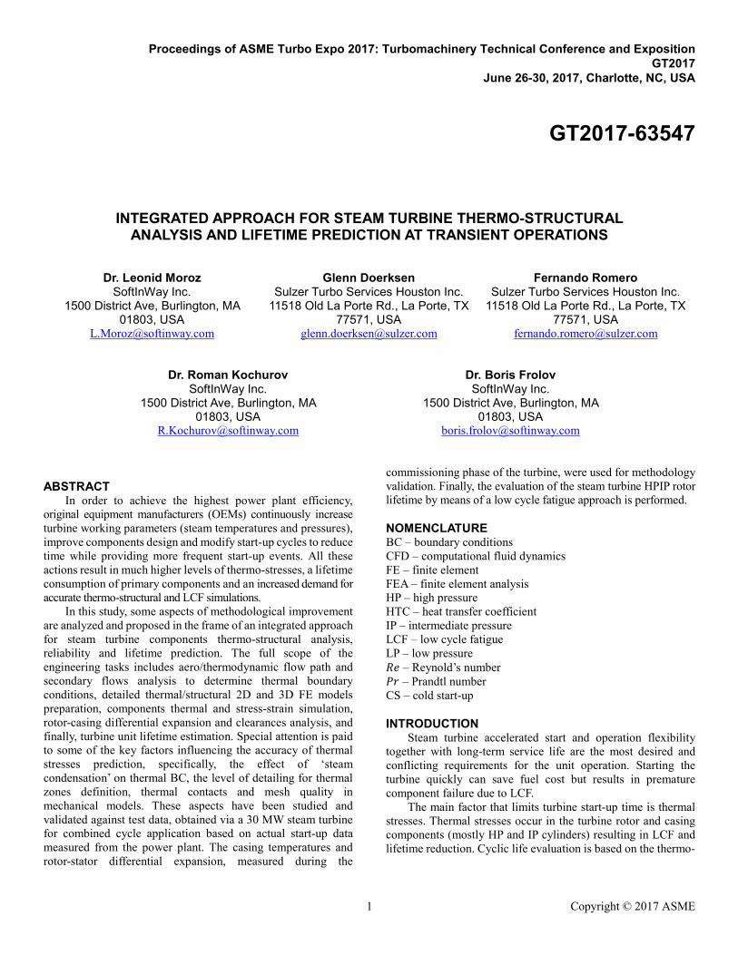
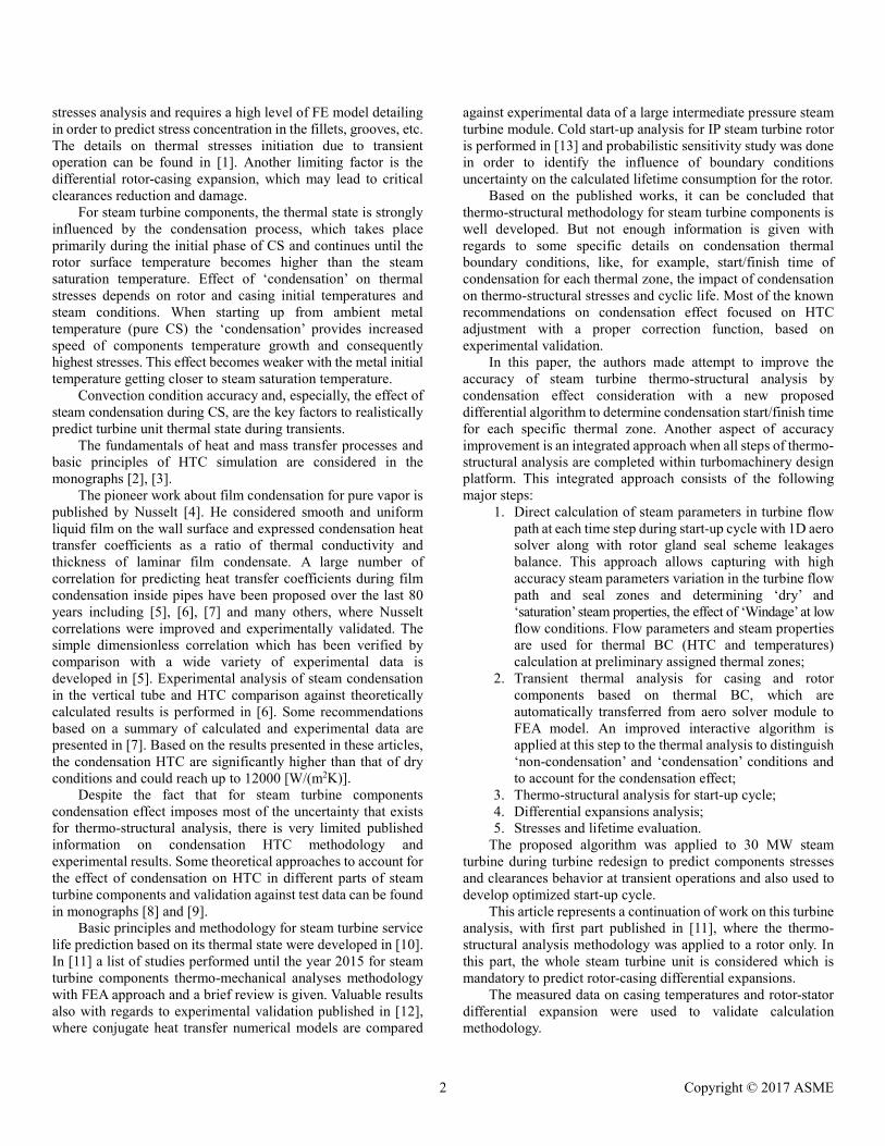
from simple steam oil-fired to natural gas-fired combined cycle. The project was led by Sulzer Turbo Services Houston Inc., which was responsible for steam turbine redesign and manufacture in cooperation with SoftInWay, Inc. engineering team. The turbines upgrades have been performed for 3 similar 30 MW steam turbine units (see Fig. 1 and Fig. 2) to adjust for operation at combined cycle parameters and to improve efficiency and performance.
Figure 1: 30MW Steam Turbine Model
Figure 2: 30MW Steam Turbine Unit – Photo from Power Plant
The following upgrade options have been applied to the
steam turbine in comparison with original design: 1. New flow path for HPIP and LP turbines with high
efficient rotor and stator blades; 2. Upgraded end-packing and blading seals – resulted in
new reduced clearances; 3. Modified design and off-design conditions, optimized
for combined operation; 4. Modified start-up curves to reduce startup time; 5. HPIP rotors from a new material with better mechanical
properties.
All these design changes required the full scope of thermo-mechanical analyses which are presented here by the example of the steam turbine cold start-up.
Some of the steam turbine operating parameters for the design point are presented below:
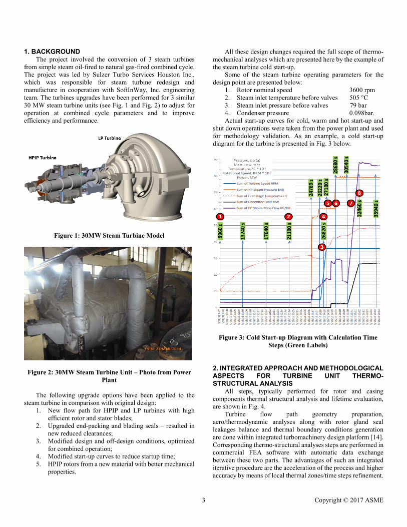
1. Rotor nominal speed 3600 rpm 2. Steam inlet temperature before valves 505 °C 3. Steam inlet pressure before valves 79 bar 4. Condenser pressure 0.098bar. Actual start-up curves for cold, warm and hot start-up and
shut down operations were taken from the power plant and used for methodology validation. As an example, a cold start-up diagram for the turbine is presented in Fig. 3 below.
Figure 3: Cold Start-up Diagram with Calculation Time Steps (Green Labels)
2. INTEGRATED APPROACH AND METHODOLOGICAL ASPECTS FOR TURBINE UNIT THERMO-STRUCTURAL ANALYSIS
All steps, typically performed for rotor and casing components thermal structural analysis and lifetime evaluation, are shown in Fig. 4.
Turbine flow path geometry preparation, aero/thermodynamic analyses along with rotor gland seal leakages balance and thermal boundary conditions generation are done within integrated turbomachinery design platform [14]. Corresponding thermo-structural analyses steps are performed in commercial FEA software with automatic data exchange between these two parts. The advantages of such an integrated iterative procedure are the acceleration of the process and higher accuracy by means of local thermal zones/time steps refinement.
3 Copyright © 2017 ASME
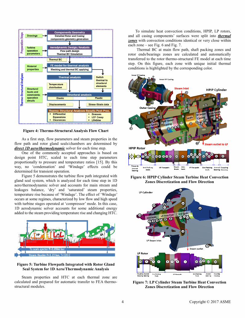
Figure 4: Thermo-Structural Analysis Flow Chart
As a first step, flow parameters and steam properties in the flow path and rotor gland seals/chambers are determined by direct 1D aero/thermodynamic solver for each time step.
One of the commonly accepted approaches is based on design point HTC, scaled to each time step parameters proportionally to pressure and temperature ratios [15]. By this way, no ‘condensation’ and ‘Windage’ effects could be determined for transient operation.
Figure 5 demonstrates the turbine flow path integrated with gland seal system, which is analyzed for each time step in 1D aero/thermodynamic solver and accounts for main stream and leakages balance, ‘dry’ and ‘saturated’ steam properties, temperature rise because of ‘Windage’. The effect of ‘Windage’ occurs at some regimes, characterized by low flow and high speed with turbine stages operated at ‘compressor’ mode. In this case, 1D aerodynamic solver accounts for some additional energy added to the steam providing temperature rise and changing HTC.
Figure 5: Turbine Flowpath Integrated with Rotor Gland Seal System for 1D Aero/Thermodynamic Analysis
Steam properties and HTC at each thermal zone are
calculated and prepared for automatic transfer to FEA thermo-structural modules.
To simulate heat convection conditions, HPIP, LP rotors, and all casing components’ surfaces were split into thermal zones with convection conditions identical or very close within each zone – see Fig. 6 and Fig. 7.
Thermal BC at main flow path, shaft packing zones and rotor ends/bearings zones are calculated and automatically transferred to the rotor thermo-structural FE model at each time step. On this figure, each zone with unique initial thermal conditions is highlighted by the corresponding color.
Figure 6: HPIP Cylinder Steam Turbine Heat Convection Zones Discretization and Flow Direction
Figure 7: LP Cylinder Steam Turbine Heat Convection Zones Discretization and Flow Direction
4 Copyright © 2017 ASME
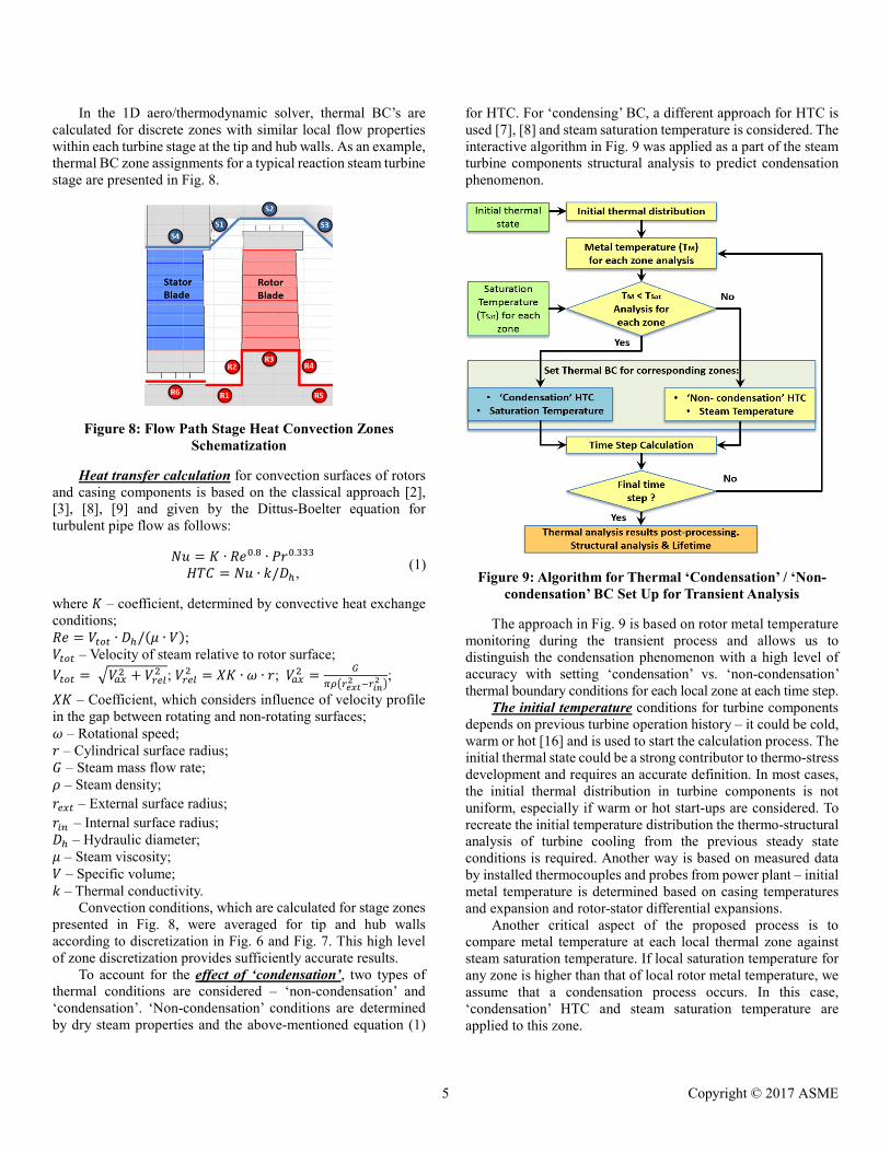
In the 1D aero/thermodynamic solver, thermal BC’s are calculated for discrete zones with similar local flow properties within each turbine stage at the tip and hub walls. As an example, thermal BC zone assignments for a typical reaction steam turbine stage are presented in Fig. 8.
Figure 8: Flow Path Stage Heat Convection Zones Schematization
Heat transfer calculation for convection surfaces of rotors
and casing components is based on the classical approach [2], [3], [8], [9] and given by the Dittus-Boelter equation for turbulent pipe flow as follows:
𝑁𝑁𝑁𝑁 = 𝐾𝐾 ∙ 𝑅𝑅𝑅𝑅0.8 ∙ 𝑃𝑃𝑃𝑃0.333 (1) 𝐻𝐻𝐻𝐻𝐻𝐻 = 𝑁𝑁𝑁𝑁 ∙ 𝑘𝑘/𝐷𝐷ℎ, where 𝐾𝐾 – coefficient, determined by convective heat exchange conditions; 𝑅𝑅𝑅𝑅 = 𝑉𝑉𝑡𝑡𝑡𝑡𝑡𝑡 ∙ 𝐷𝐷ℎ/(𝜇𝜇 ∙ 𝑉𝑉); 𝑉𝑉𝑡𝑡𝑡𝑡𝑡𝑡 – Velocity of steam relative to rotor surface; 𝑉𝑉𝑡𝑡𝑡𝑡𝑡𝑡 = �𝑉𝑉𝑎𝑎𝑎𝑎2 + 𝑉𝑉𝑟𝑟𝑟𝑟𝑟𝑟2 ; 𝑉𝑉𝑟𝑟𝑟𝑟𝑟𝑟2 = 𝑋𝑋𝐾𝐾 ∙ 𝜔𝜔 ∙ 𝑃𝑃; 𝑉𝑉𝑎𝑎𝑎𝑎2 = 𝐺𝐺
𝜋𝜋𝜋𝜋�𝑟𝑟𝑒𝑒𝑒𝑒𝑒𝑒2 −𝑟𝑟𝑖𝑖𝑖𝑖
2 �;
𝑋𝑋𝐾𝐾 – Coefficient, which considers influence of velocity profile in the gap between rotating and non-rotating surfaces; 𝜔𝜔 – Rotational speed; 𝑃𝑃 – Cylindrical surface radius; 𝐺𝐺 – Steam mass flow rate; 𝜌𝜌 – Steam density; 𝑃𝑃𝑟𝑟𝑎𝑎𝑡𝑡 – External surface radius; 𝑃𝑃𝑖𝑖𝑖𝑖 – Internal surface radius; 𝐷𝐷ℎ – Hydraulic diameter; 𝜇𝜇 – Steam viscosity; 𝑉𝑉 – Specific volume; 𝑘𝑘 – Thermal conductivity.
Convection conditions, which are calculated for stage zones presented in Fig. 8, were averaged for tip and hub walls according to discretization in Fig. 6 and Fig. 7. This high level of zone discretization provides sufficiently accurate results.
To account for the effect of ‘condensation’, two types of thermal conditions are considered – ‘non-condensation’ and ‘condensation’. ‘Non-condensation’ conditions are determined by dry steam properties and the above-mentioned equation (1)
for HTC. For ‘condensing’ BC, a different approach for HTC is used [7], [8] and steam saturation temperature is considered. The interactive algorithm in Fig. 9 was applied as a part of the steam turbine components structural analysis to predict condensation phenomenon.
Figure 9: Algorithm for Thermal ‘Condensation’ / ‘Non-condensation’ BC Set Up for Transient Analysis
The approach in Fig. 9 is based on rotor metal temperature
monitoring during the transient process and allows us to distinguish the condensation phenomenon with a high level of accuracy with setting ‘condensation’ vs. ‘non-condensation’ thermal boundary conditions for each local zone at each time step.
The initial temperature conditions for turbine components depends on previous turbine operation history – it could be cold, warm or hot [16] and is used to start the calculation process. The initial thermal state could be a strong contributor to thermo-stress development and requires an accurate definition. In most cases, the initial thermal distribution in turbine components is not uniform, especially if warm or hot start-ups are considered. To recreate the initial temperature distribution the thermo-structural analysis of turbine cooling from the previous steady state conditions is required. Another way is based on measured data by installed thermocouples and probes from power plant – initial metal temperature is determined based on casing temperatures and expansion and rotor-stator differential expansions.
Another critical aspect of the proposed process is to compare metal temperature at each local thermal zone against steam saturation temperature. If local saturation temperature for any zone is higher than that of local rotor metal temperature, we assume that a condensation process occurs. In this case, ‘condensation’ HTC and steam saturation temperature are applied to this zone.
5 Copyright © 2017 ASME
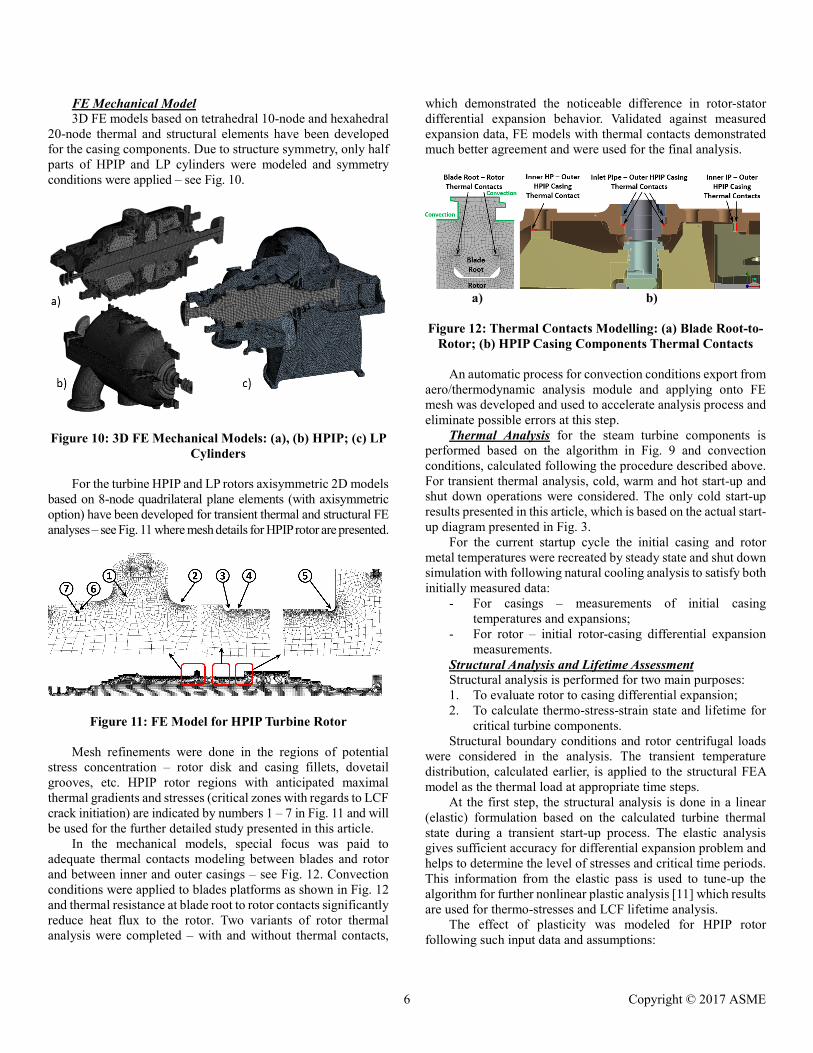
FE Mechanical Model 3D FE models based on tetrahedral 10-node and hexahedral
20-node thermal and structural elements have been developed for the casing components. Due to structure symmetry, only half parts of HPIP and LP cylinders were modeled and symmetry conditions were applied – see Fig. 10.
Figure 10: 3D FE Mechanical Models: (a), (b) HPIP; (c) LP
Cylinders For the turbine HPIP and LP rotors axisymmetric 2D models
based on 8-node quadrilateral plane elements (with axisymmetric option) have been developed for transient thermal and structural FE analyses – see Fig. 11 where mesh details for HPIP rotor are presented.
Figure 11: FE Model for HPIP Turbine Rotor
Mesh refinements were done in the regions of potential stress concentration – rotor disk and casing fillets, dovetail grooves, etc. HPIP rotor regions with anticipated maximal thermal gradients and stresses (critical zones with regards to LCF crack initiation) are indicated by numbers 1 – 7 in Fig. 11 and will be used for the further detailed study presented in this article.
In the mechanical models, special focus was paid to adequate thermal contacts modeling between blades and rotor and between inner and outer casings – see Fig. 12. Convection conditions were applied to blades platforms as shown in Fig. 12 and thermal resistance at blade root to rotor contacts significantly reduce heat flux to the rotor. Two variants of rotor thermal analysis were completed – with and without thermal contacts,
which demonstrated the noticeable difference in rotor-stator differential expansion behavior. Validated against measured expansion data, FE models with thermal contacts demonstrated much better agreement and were used for the final analysis.
a) b) Figure 12: Thermal Contacts Modelling: (a) Blade Root-to-
Rotor; (b) HPIP Casing Components Thermal Contacts An automatic process for convection conditions export from
aero/thermodynamic analysis module and applying onto FE mesh was developed and used to accelerate analysis process and eliminate possible errors at this step.
Thermal Analysis for the steam turbine components is performed based on the algorithm in Fig. 9 and convection conditions, calculated following the procedure described above. For transient thermal analysis, cold, warm and hot start-up and shut down operations were considered. The only cold start-up results presented in this article, which is based on the actual start-up diagram presented in Fig. 3.
For the current startup cycle the initial casing and rotor metal temperatures were recreated by steady state and shut down simulation with following natural cooling analysis to satisfy both initially measured data:
- For casings – measurements of initial casing temperatures and expansions;
- For rotor – initial rotor-casing differential expansion measurements.
Structural Analysis and Lifetime Assessment Structural analysis is performed for two main purposes: 1. To evaluate rotor to casing differential expansion; 2. To calculate thermo-stress-strain state and lifetime for
critical turbine components. Structural boundary conditions and rotor centrifugal loads
were considered in the analysis. The transient temperature distribution, calculated earlier, is applied to the structural FEA model as the thermal load at appropriate time steps.
At the first step, the structural analysis is done in a linear (elastic) formulation based on the calculated turbine thermal state during a transient start-up process. The elastic analysis gives sufficient accuracy for differential expansion problem and helps to determine the level of stresses and critical time periods. This information from the elastic pass is used to tune-up the algorithm for further nonlinear plastic analysis [11] which results are used for thermo-stresses and LCF lifetime analysis.
The effect of plasticity was modeled for HPIP rotor following such input data and assumptions:
6 Copyright © 2017 ASME
1. Actual rotor material stress-strain curves at room and elevated temperature conditions are used;
2. The rotor material is cyclically hardened. A multi-linear kinematic hardening plasticity model is applied;
3. The non-linear analysis model includes the Baushinger effect and geometrical nonlinearity;
4. Two full cycles of rotor transient plastic stress analyses were performed in series: start-up – running – shut down -to reach stabilized stress-strain hysteresis loops for each region of interest.
One of the rotor life limiting factors is thermo-mechanical fatigue due to varying stresses during transient operation. Another contributor to limiting rotor lifetime in the high-temperature applications is a creep. The current article is focused on the effect of LCF estimation only and creep effect is not considered in the present study.
LCF analysis is performed based on calculated thermo-mechanical stress-strain state prediction in a non-linear plastic statement and experimental strain-life (ɛ-N) curves for components’ material. The theoretical aspects and details for LCF analysis can be found in [1] and the procedure was described in [11].
3. ANALYSIS RESULTS AND VALIDATION AGAINST TEST DATA.
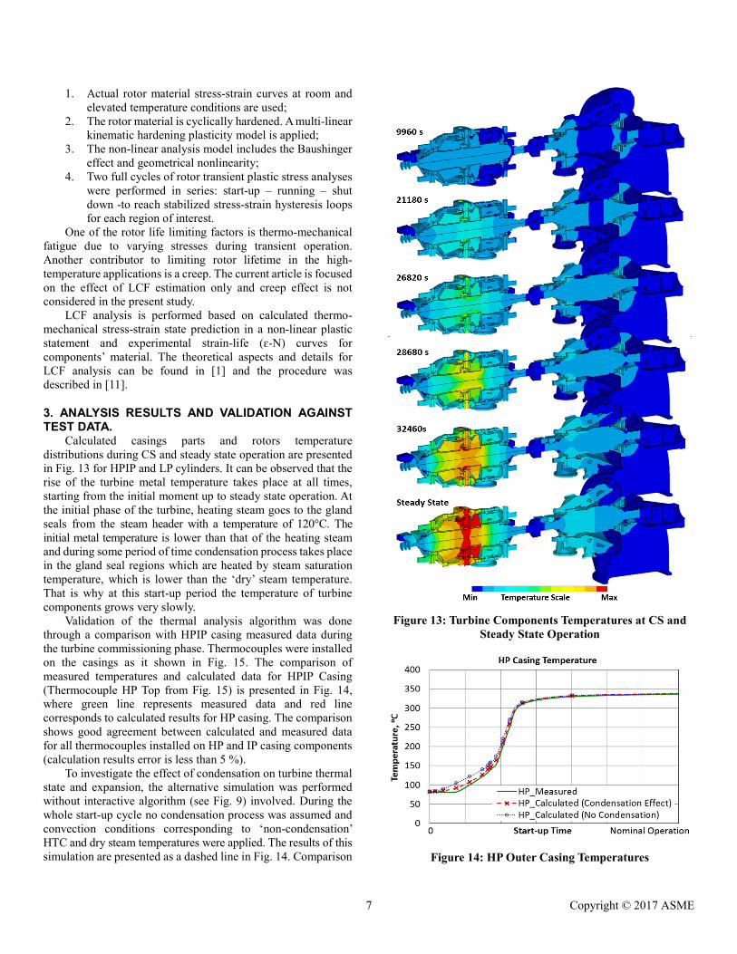
Calculated casings parts and rotors temperature distributions during CS and steady state operation are presented in Fig. 13 for HPIP and LP cylinders. It can be observed that the rise of the turbine metal temperature takes place at all times, starting from the initial moment up to steady state operation. At the initial phase of the turbine, heating steam goes to the gland seals from the steam header with a temperature of 120°C. The initial metal temperature is lower than that of the heating steam and during some period of time condensation process takes place in the gland seal regions which are heated by steam saturation temperature, which is lower than the ‘dry’ steam temperature. That is why at this start-up period the temperature of turbine components grows very slowly.
Validation of the thermal analysis algorithm was done through a comparison with HPIP casing measured data during the turbine commissioning phase. Thermocouples were installed on the casings as it shown in Fig. 15. The comparison of measured temperatures and calculated data for HPIP Casing (Thermocouple HP Top from Fig. 15) is presented in Fig. 14, where green line represents measured data and red line corresponds to calculated results for HP casing. The comparison shows good agreement between calculated and measured data for all thermocouples installed on HP and IP casing components (calculation results error is less than 5 %).
To investigate the effect of condensation on turbine thermal state and expansion, the alternative simulation was performed without interactive algorithm (see Fig. 9) involved. During the whole start-up cycle no condensation process was assumed and convection conditions corresponding to ‘non-condensation’ HTC and dry steam temperatures were applied. The results of this simulation are presented as a dashed line in Fig. 14. Comparison
Figure 13: Turbine Components Temperatures at CS and
Steady State Operation
Figure 14: HP Outer Casing Temperatures
7 Copyright © 2017 ASME
with experimental results shows casing overheating at the initial phase of start-up and the difference between measured data and the simulation results reaches up to 20%.
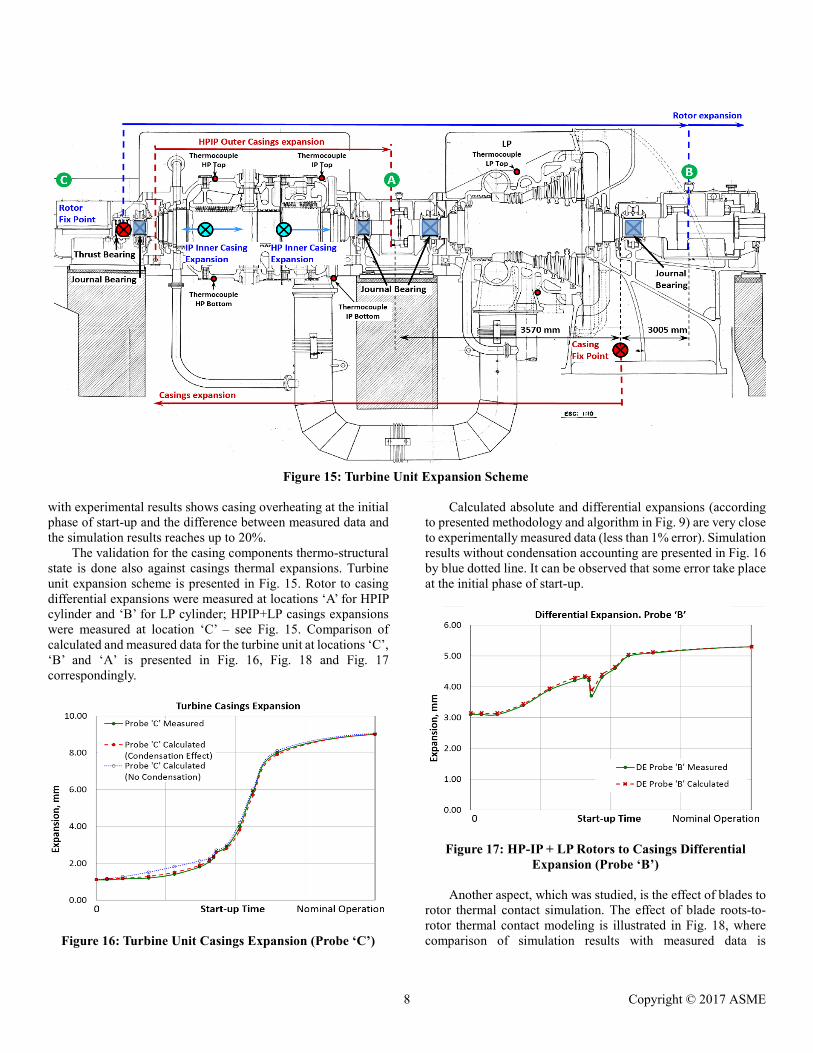
The validation for the casing components thermo-structural state is done also against casings thermal expansions. Turbine unit expansion scheme is presented in Fig. 15. Rotor to casing differential expansions were measured at locations ‘A’ for HPIP cylinder and ‘B’ for LP cylinder; HPIP+LP casings expansions were measured at location ‘C’ – see Fig. 15. Comparison of calculated and measured data for the turbine unit at locations ‘C’, ‘B’ and ‘A’ is presented in Fig. 16, Fig. 18 and Fig. 17 correspondingly.
Figure 16: Turbine Unit Casings Expansion (Probe ‘C’)
Calculated absolute and differential expansions (according to presented methodology and algorithm in Fig. 9) are very close to experimentally measured data (less than 1% error). Simulation results without condensation accounting are presented in Fig. 16 by blue dotted line. It can be observed that some error take place at the initial phase of start-up.
Figure 17: HP-IP + LP Rotors to Casings Differential Expansion (Probe ‘B’)
Another aspect, which was studied, is the effect of blades to
rotor thermal contact simulation. The effect of blade roots-to-rotor thermal contact modeling is illustrated in Fig. 18, where comparison of simulation results with measured data is
Figure 15: Turbine Unit Expansion Scheme
8 Copyright © 2017 ASME
presented. The red line of Fig. 18 corresponds to blade roots-to-rotor thermal contact model (see Fig. 12) and dotted blue line to simplified model with no thermal contacts. At the initial phase of heating results well agree with measured data. But at the time of turbine loading, when steam flow rate increase, the simplified model demonstrates rotor overheating.
Figure 18: HPIP Rotor to Casing Differential Expansion (Probe ‘A’)
4. THERMO-STRESSES ANALYSES RESULTS AND DISCUSSION
The thermal gradients cause thermal stresses which can be observed during transient and steady state operation and contribute a significant portion of stresses into the entire stress-strain state.
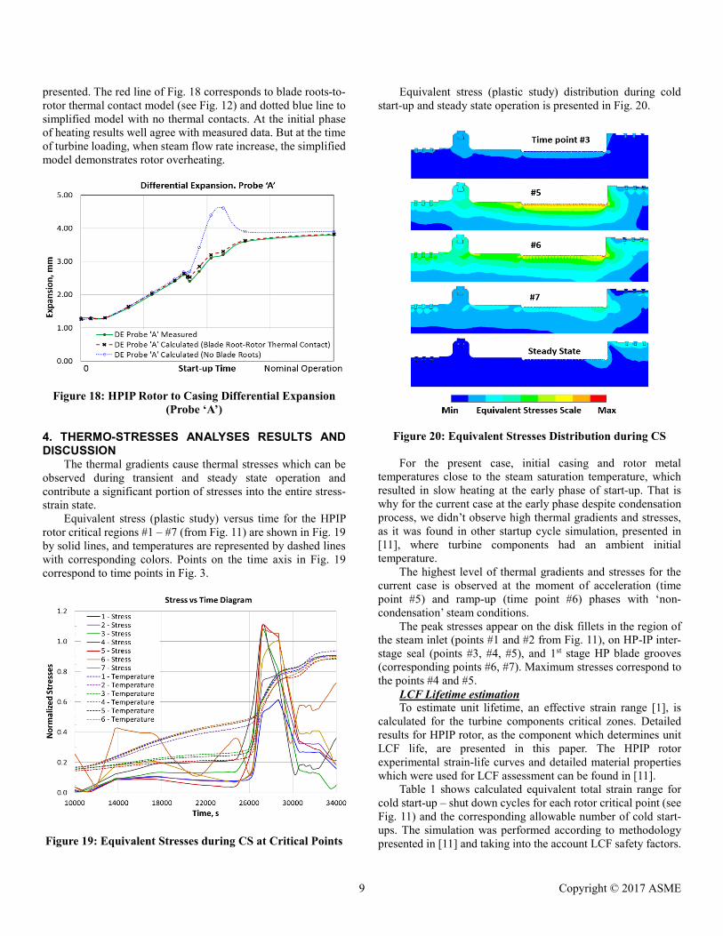
Equivalent stress (plastic study) versus time for the HPIP rotor critical regions #1 – #7 (from Fig. 11) are shown in Fig. 19 by solid lines, and temperatures are represented by dashed lines with corresponding colors. Points on the time axis in Fig. 19 correspond to time points in Fig. 3.
Figure 19: Equivalent Stresses during CS at Critical Points
Equivalent stress (plastic study) distribution during cold start-up and steady state operation is presented in Fig. 20.
Figure 20: Equivalent Stresses Distribution during CS
For the present case, initial casing and rotor metal temperatures close to the steam saturation temperature, which resulted in slow heating at the early phase of start-up. That is why for the current case at the early phase despite condensation process, we didn’t observe high thermal gradients and stresses, as it was found in other startup cycle simulation, presented in [11], where turbine components had an ambient initial temperature.
The highest level of thermal gradients and stresses for the current case is observed at the moment of acceleration (time point #5) and ramp-up (time point #6) phases with ‘non-condensation’ steam conditions.
The peak stresses appear on the disk fillets in the region of the steam inlet (points #1 and #2 from Fig. 11), on HP-IP inter-stage seal (points #3, #4, #5), and 1st stage HP blade grooves (corresponding points #6, #7). Maximum stresses correspond to the points #4 and #5.
LCF Lifetime estimation To estimate unit lifetime, an effective strain range [1], is
calculated for the turbine components critical zones. Detailed results for HPIP rotor, as the component which determines unit LCF life, are presented in this paper. The HPIP rotor experimental strain-life curves and detailed material properties which were used for LCF assessment can be found in [11].
Table 1 shows calculated equivalent total strain range for cold start-up – shut down cycles for each rotor critical point (see Fig. 11) and the corresponding allowable number of cold start-ups. The simulation was performed according to methodology presented in [11] and taking into the account LCF safety factors.
9 Copyright © 2017 ASME
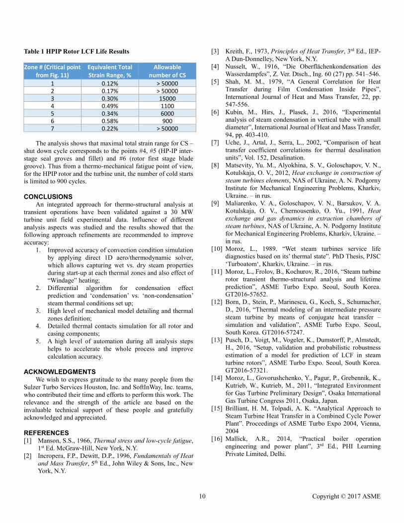
Table 1 HPIP Rotor LCF Life Results Zone # (Critical point
from Fig. 11) Equivalent Total Strain Range, %
Allowable number of CS
1 0.12% > 50000 2 0.17% > 50000 3 0.30% 15000
4 0.49% 1100 5 0.34% 6000 6 0.58% 900 7 0.22% > 50000
The analysis shows that maximal total strain range for CS –
shut down cycle corresponds to the points #4, #5 (HP-IP inter-stage seal groves and fillet) and #6 (rotor first stage blade groove). Thus from a thermo-mechanical fatigue point of view, for the HPIP rotor and the turbine unit, the number of cold starts is limited to 900 cycles.
CONCLUSIONS An integrated approach for thermo-structural analysis at
transient operations have been validated against a 30 MW turbine unit field experimental data. Influence of different analysis aspects was studied and the results showed that the following approach refinements are recommended to improve accuracy:
1. Improved accuracy of convection condition simulation by applying direct 1D aero/thermodynamic solver, which allows capturing wet vs. dry steam properties during start-up at each thermal zones and also effect of “Windage” heating;
2. Differential algorithm for condensation effect prediction and ‘condensation’ vs. ‘non-condensation’ steam thermal conditions set up;
3. High level of mechanical model detailing and thermal zones definition;
4. Detailed thermal contacts simulation for all rotor and casing components;
5. A high level of automation during all analysis steps helps to accelerate the whole process and improve calculation accuracy.
ACKNOWLEDGMENTS We wish to express gratitude to the many people from the
Sulzer Turbo Services Houston, Inc. and SoftInWay, Inc. teams, who contributed their time and efforts to perform this work. The relevance and the strength of the article are based on the invaluable technical support of these people and gratefully acknowledged and appreciated.
REFERENCES [1] Manson, S.S., 1966, Thermal stress and low-cycle fatigue,
1st Ed. McGraw-Hill, New York, N.Y. [2] Incropera, F.P., Dewitt, D.P., 1996, Fundamentals of Heat
and Mass Transfer, 5th Ed., John Wiley & Sons, Inc., New York, N.Y.
[3] Kreith, F., 1973, Principles of Heat Transfer, 3rd Ed., IEP-A Dun-Donnelley, New York, N.Y.
[4] Nusselt, W., 1916, “Die Oberflächenkondensation des Wasserdampfes”, Z. Ver. Dtsch., Ing. 60 (27) pp. 541–546.
[5] Shah, M. M., 1979, “A General Correlation for Heat Transfer during Film Condensation Inside Pipes”, International Journal of Heat and Mass Transfer, 22, pp. 547-556.
[6] Kubín, M., Hirs, J., Plasek, J., 2016, “Experimental analysis of steam condensation in vertical tube with small diameter”, International Journal of Heat and Mass Transfer, 94, pp. 403-410.
[7] Uche, J., Artal, J., Serra, L., 2002, “Comparison of heat transfer coefficient correlations for thermal desalination units”, Vol. 152, Desalination.
[8] Matsevity, Yu. М., Alyokhina, S. V., Goloschapov, V. N., Kotulskaja, О. V., 2012, Heat exchange in construction of steam turbines elements, NAS of Ukraine, A. N. Podgorny Institute for Mechanical Engineering Problems, Kharkiv, Ukraine. – in rus.
[9] Maliarenko, V. A., Goloschapov, V. N., Barsukov, V. A. Kotulskaja, О. V., Chernousenko, O. Yu., 1991, Heat exchange and gas dynamics in extraction chambers of steam turbines, NAS of Ukraine, A. N. Podgorny Institute for Mechanical Engineering Problems, Kharkiv, Ukraine. – in rus.
[10] Moroz, L., 1989. “Wet steam turbines service life diagnostics based on its’ thermal state”. PhD Thesis, PJSC ‘Turboatom‘, Kharkiv, Ukraine. – in rus.
[11] Moroz, L., Frolov, B., Kochurov, R., 2016, “Steam turbine rotor transient thermo-structural analysis and lifetime prediction”, ASME Turbo Expo. Seoul, South Korea. GT2016-57652.
[12] Born, D., Stein, P., Marinescu, G., Koch, S., Schumacher, D., 2016, “Thermal modeling of an intermediate pressure steam turbine by means of conjugate heat transfer – simulation and validation”, ASME Turbo Expo. Seoul, South Korea. GT2016-57247.
[13] Pusch, D., Voigt, M., Vogeler, K., Dumstorff, P., Almstedt, H., 2016, “Setup, validation and probabilistic robustness estimation of a model for prediction of LCF in steam turbine rotors”, ASME Turbo Expo. Seoul, South Korea. GT2016-57321.
[14] Moroz, L., Govorushchenko, Y., Pagur, P., Grebennik, K., Kutrieb, W., Kutrieb, M., 2011, “Integrated Environment for Gas Turbine Preliminary Design”, Osaka International Gas Turbine Congress 2011, Osaka, Japan.
[15] Brilliant, H. M, Tolpadi, A. K. “Analytical Approach to Steam Turbine Heat Transfer in a Combined Cycle Power Plant”. Proceedings of ASME Turbo Expo 2004, Vienna, 2004
[16] Mallick, A.R., 2014, “Practical boiler operation engineering and power plant”, 3rd Ed., PHI Learning Private Limited, Delhi.
10 Copyright © 2017 ASME