3902e NotPowerdrive en - Leroy-Somer INSTALLATION MANUAL POWERDRIVE Variable speed drive LEROY-SOMER...
48
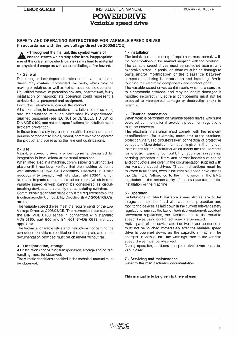
This manual is to be given to the end user POWERDRIVE Variable speed drive Micro regulator Input/Output command Mains supply ASIC PWM Carrier power supply (Optional encoder or sensor) MD Encoder (optional) Control card M IGBT IGBT IGBT Installation manual 3902 en - 2010.05 / e
Transcript of 3902e NotPowerdrive en - Leroy-Somer INSTALLATION MANUAL POWERDRIVE Variable speed drive LEROY-SOMER...
This manual is to be given
to the end user
POWERDRIVE Variable speed drive
Micro regulatorInput/Output
command
Mains supply
ASIC PWM
Carrier power supply
(Optional encoder or sensor)
MD Encoder(optional)
Control card
M
IGBT IGBT IGBT
Installation manual
3902 en - 2010.05 / e
2
INSTALLATION MANUAL
POWERDRIVEVariable speed drive
LEROY-SOMER 3902 en - 2010.05 / e
NOTE
LEROY-SOMER reserves the right to modify the characteristics of its products at any time in order to incorporate the latesttechnological developments. The information contained in this document may therefore be changed without notice.
CAUTION
For the user's own safety, this variable speed drive must be connected to an approved earth ( terminal).
If accidentally starting the installation is likely to cause a risk to personnel or the machines being driven, it is essential to complywith the power connection diagrams recommended in this manual.
The variable speed drive is fitted with safety devices which, in the event of a problem, control stopping and thus stop the motor.The motor itself can become jammed for mechanical reasons. Voltage fluctuations, and in particular power cuts, may also causethe motor to stop. The removal of the causes of the shutdown can lead to restarting, which may be dangerous for certainmachines or installations.In such cases, it is essential that the user takes appropriate precautions against the motor restarting after an unscheduled stop.
The variable speed drive is designed to be able to supply a motor and the driven machine above its rated speed.If the motor or the machine are not mechanically designed to withstand such speeds, the user may be exposed to serious dangerresulting from their mechanical deterioration.It is important that the user checks that the installation can withstand it before programming a high speed.
The variable speed drive which is the subject of this manual is designed to be integrated in an installation or an electricalmachine, and can under no circumstances be considered to be a safety device. It is therefore the responsibility of the machinemanufacturer, the designer of the installation or the user to take all necessary precautions to ensure that the system complieswith current standards, and to provide any devices required to ensure the safety of equipment and personnel.
LEROY-SOMER declines all responsibility in the event of the above recommendations not being observed.
........................................
This manual only describes the general features, characteristics and installation of the POWERDRIVE. Forcommissioning, refer to manual 3871.
3
INSTALLATION MANUAL
POWERDRIVEVariable speed drive
LEROY-SOMER 3902 en - 2010.05 / e
• Throughout the manual, this symbol warns of consequences which may arise from inappropriate
use of the drive, since electrical risks may lead to material or physical damage as well as constituting a fire hazard.
1 - GeneralDepending on their degree of protection, the variable speeddrives may contain unprotected live parts, which may bemoving or rotating, as well as hot surfaces, during operation.Unjustified removal of protection devices, incorrect use, faultyinstallation or inappropriate operation could represent aserious risk to personnel and equipment.For further information, consult the manual.All work relating to transportation, installation, commissioningand maintenance must be performed by experienced,qualified personnel (see IEC 364 or CENELEC HD 384 orDIN VDE 0100, and national specifications for installation andaccident prevention).In these basic safety instructions, qualified personnel meanspersons competent to install, mount, commission and operatethe product and possessing the relevant qualifications.
2 - UseVariable speed drives are components designed forintegration in installations or electrical machines.When integrated in a machine, commissioning must not takeplace until it has been verified that the machine conformswith directive 2006/42/CE (Machinery Directive). It is alsonecessary to comply with standard EN 60204, whichstipulates in particular that electrical actuators (which includevariable speed drives) cannot be considered as circuit-breaking devices and certainly not as isolating switches.Commissioning can take place only if the requirements of theElectromagnetic Compatibility Directive (EMC 2004/108/CE)are met.The variable speed drives meet the requirements of the LowVoltage Directive 2006/95/CE. The harmonised standards ofthe DIN VDE 0160 series in connection with standardVDE 0660, part 500 and EN 60146/VDE 0558 are alsoapplicable.The technical characteristics and instructions concerning theconnection conditions specified on the nameplate and in thedocumentation provided must be observed without fail.
3 - Transportation, storageAll instructions concerning transportation, storage and correcthandling must be observed.The climatic conditions specified in the technical manual mustbe observed.
4 - InstallationThe installation and cooling of equipment must comply withthe specifications in the manual supplied with the product.The variable speed drives must be protected against anyexcessive stress. In particular, there must be no damage toparts and/or modification of the clearance betweencomponents during transportation and handling. Avoidtouching the electronic components and contact parts.The variable speed drives contain parts which are sensitiveto electrostatic stresses and may be easily damaged ifhandled incorrectly. Electrical components must not beexposed to mechanical damage or destruction (risks tohealth!).
5 - Electrical connectionWhen work is performed on variable speed drives which arepowered up, the national accident prevention regulationsmust be observed.The electrical installation must comply with the relevantspecifications (for example, conductor cross-sections,protection via fused circuit-breaker, connection of protectiveconductor). More detailed information is given in the manual.Instructions for an installation which meets the requirementsfor electromagnetic compatibility, such as screening,earthing, presence of filters and correct insertion of cablesand conductors, are given in the documentation supplied withthe variable speed drives. These instructions must befollowed in all cases, even if the variable speed drive carriesthe CE mark. Adherence to the limits given in the EMClegislation is the responsibility of the manufacturer of theinstallation or the machine.
6 - OperationInstallations in which variable speed drives are to beintegrated must be fitted with additional protection andmonitoring devices as laid down in the current relevant safetyregulations, such as the law on technical equipment, accidentprevention regulations, etc. Modifications to the variablespeed drives using control software are permitted.Active parts of the device and the live power connectionsmust not be touched immediately after the variable speeddrive is powered down, as the capacitors may still becharged. In view of this, the warnings fixed to the variablespeed drives must be observed.During operation, all doors and protective covers must bekept closed.
7 - Servicing and maintenanceRefer to the manufacturer's documentation.
This manual is to be given to the end user.
SAFETY AND OPERATING INSTRUCTIONS FOR VARIABLE SPEED DRIVES(In accordance with the low voltage directive 2006/95/CE)
4
INSTALLATION MANUAL
POWERDRIVEVariable speed drive
LEROY-SOMER 3902 en - 2010.05 / e
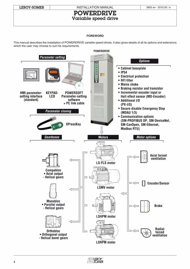
FOREWORD
This manual describes the installation of POWERDRIVE variable speed drives. It also gives details of all its options and extensionswhich the user may choose to suit his requirements.
Radialforced
ventilation
Compabloc• Axial output- Helical gears
Orthobloc• Orthogonal output- Helical bevel gears
Manubloc• Parallel output- Helical gears
MotorsGearboxes
POWERDRIVE
• Cabinet baseplate• IP54• Electrical protection• RFI filter• Mains choke• Braking resistor and transistor• Incremental encoder input or Hall effect sensor (MD-Encoder)• Additional I/O (PX-I/O)• Secure disable Emergency Stop (MDAU 1/3)• Communication options (SM-PROFIBUS DP, SM-DeviceNet, SM-CanOpen, SM-Ethernet, Modbus RTU)
Options
LS-FLS motor
LSMV motor
LSHPM motor
LSRPM motor
Brake
Axial forcedventilation
Encoder/Sensor
Motor options
KEYPAD-LCD
HMI parameter-setting interface
(standard)
POWERSOFTParameter-setting
software+ PC link cable
XPressKey
Parameter setting
Parameter cloning
5
INSTALLATION MANUAL
POWERDRIVEVariable speed drive
CONTENTS
LEROY-SOMER 3902 en - 2010.05 / e
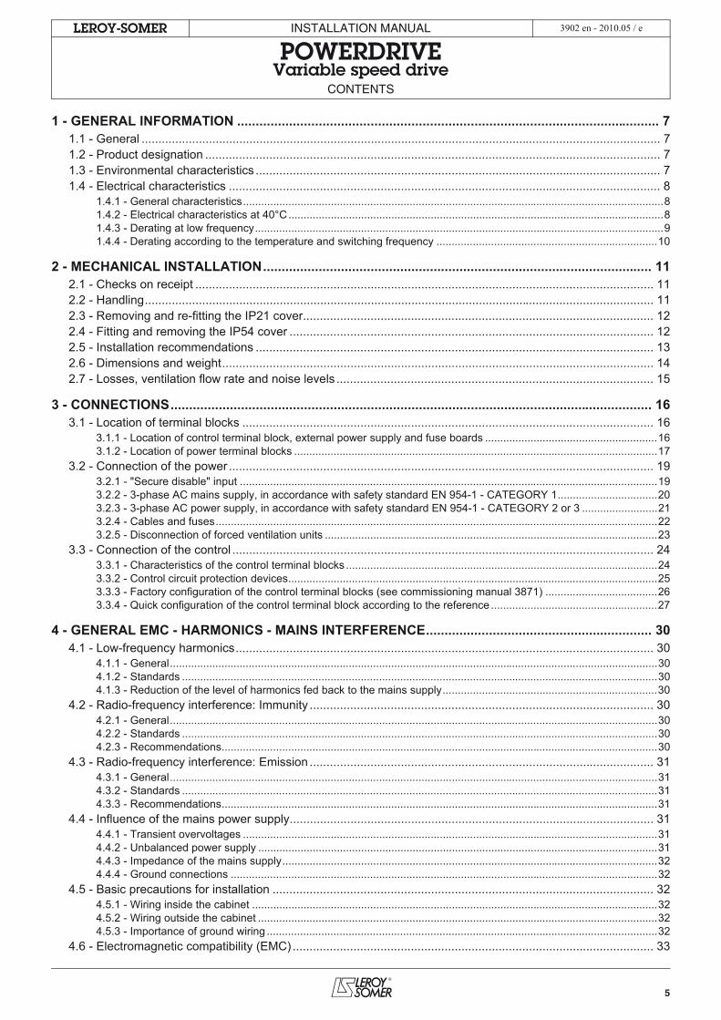
1 - GENERAL INFORMATION .................................................................................................................. 71.1 - General .......................................................................................................................................................... 71.2 - Product designation ....................................................................................................................................... 71.3 - Environmental characteristics ........................................................................................................................ 71.4 - Electrical characteristics ................................................................................................................................ 8
1.4.1 - General characteristics...........................................................................................................................................81.4.2 - Electrical characteristics at 40°C............................................................................................................................81.4.3 - Derating at low frequency.......................................................................................................................................91.4.4 - Derating according to the temperature and switching frequency .........................................................................10
2 - MECHANICAL INSTALLATION......................................................................................................... 112.1 - Checks on receipt ........................................................................................................................................ 112.2 - Handling....................................................................................................................................................... 112.3 - Removing and re-fitting the IP21 cover........................................................................................................ 122.4 - Fitting and removing the IP54 cover ............................................................................................................ 122.5 - Installation recommendations ...................................................................................................................... 132.6 - Dimensions and weight................................................................................................................................ 142.7 - Losses, ventilation flow rate and noise levels .............................................................................................. 15
3 - CONNECTIONS.................................................................................................................................. 163.1 - Location of terminal blocks .......................................................................................................................... 16
3.1.1 - Location of control terminal block, external power supply and fuse boards .........................................................163.1.2 - Location of power terminal blocks ........................................................................................................................17
3.2 - Connection of the power .............................................................................................................................. 193.2.1 - "Secure disable" input ..........................................................................................................................................193.2.2 - 3-phase AC mains supply, in accordance with safety standard EN 954-1 - CATEGORY 1.................................203.2.3 - 3-phase AC power supply, in accordance with safety standard EN 954-1 - CATEGORY 2 or 3 .........................213.2.4 - Cables and fuses..................................................................................................................................................223.2.5 - Disconnection of forced ventilation units ..............................................................................................................23
3.3 - Connection of the control ............................................................................................................................. 243.3.1 - Characteristics of the control terminal blocks .......................................................................................................243.3.2 - Control circuit protection devices..........................................................................................................................253.3.3 - Factory configuration of the control terminal blocks (see commissioning manual 3871) .....................................263.3.4 - Quick configuration of the control terminal block according to the reference .......................................................27
4 - GENERAL EMC - HARMONICS - MAINS INTERFERENCE............................................................. 304.1 - Low-frequency harmonics............................................................................................................................ 30
4.1.1 - General.................................................................................................................................................................304.1.2 - Standards .............................................................................................................................................................304.1.3 - Reduction of the level of harmonics fed back to the mains supply.......................................................................30
4.2 - Radio-frequency interference: Immunity ...................................................................................................... 304.2.1 - General.................................................................................................................................................................304.2.2 - Standards .............................................................................................................................................................304.2.3 - Recommendations................................................................................................................................................30
4.3 - Radio-frequency interference: Emission ...................................................................................................... 314.3.1 - General.................................................................................................................................................................314.3.2 - Standards .............................................................................................................................................................314.3.3 - Recommendations................................................................................................................................................31
4.4 - Influence of the mains power supply............................................................................................................ 314.4.1 - Transient overvoltages .........................................................................................................................................314.4.2 - Unbalanced power supply ....................................................................................................................................314.4.3 - Impedance of the mains supply............................................................................................................................324.4.4 - Ground connections .............................................................................................................................................32
4.5 - Basic precautions for installation ................................................................................................................. 324.5.1 - Wiring inside the cabinet ......................................................................................................................................324.5.2 - Wiring outside the cabinet ....................................................................................................................................324.5.3 - Importance of ground wiring .................................................................................................................................32
4.6 - Electromagnetic compatibility (EMC) ........................................................................................................... 33
6
INSTALLATION MANUAL
POWERDRIVEVariable speed drive
CONTENTS
LEROY-SOMER 3902 en - 2010.05 / e
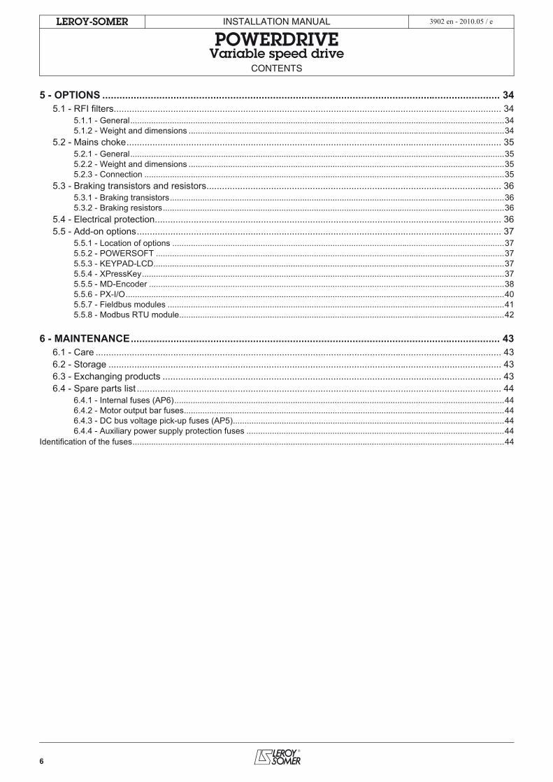
5 - OPTIONS ............................................................................................................................................ 345.1 - RFI filters...................................................................................................................................................... 34
5.1.1 - General.................................................................................................................................................................345.1.2 - Weight and dimensions ........................................................................................................................................34
5.2 - Mains choke................................................................................................................................................. 355.2.1 - General.................................................................................................................................................................355.2.2 - Weight and dimensions ........................................................................................................................................355.2.3 - Connection ...........................................................................................................................................................35
5.3 - Braking transistors and resistors.................................................................................................................. 365.3.1 - Braking transistors................................................................................................................................................365.3.2 - Braking resistors...................................................................................................................................................36
5.4 - Electrical protection...................................................................................................................................... 365.5 - Add-on options............................................................................................................................................. 37
5.5.1 - Location of options ...............................................................................................................................................375.5.2 - POWERSOFT ......................................................................................................................................................375.5.3 - KEYPAD-LCD.......................................................................................................................................................375.5.4 - XPressKey............................................................................................................................................................375.5.5 - MD-Encoder .........................................................................................................................................................385.5.6 - PX-I/O...................................................................................................................................................................405.5.7 - Fieldbus modules .................................................................................................................................................415.5.8 - Modbus RTU module............................................................................................................................................42
6 - MAINTENANCE.................................................................................................................................. 436.1 - Care ............................................................................................................................................................. 436.2 - Storage ........................................................................................................................................................ 436.3 - Exchanging products ................................................................................................................................... 436.4 - Spare parts list ............................................................................................................................................. 44
6.4.1 - Internal fuses (AP6)..............................................................................................................................................446.4.2 - Motor output bar fuses..........................................................................................................................................446.4.3 - DC bus voltage pick-up fuses (AP5).....................................................................................................................446.4.4 - Auxiliary power supply protection fuses ...............................................................................................................44
Identification of the fuses................................................................................................................................................................44
7
INSTALLATION MANUAL
POWERDRIVEVariable speed drive
GENERAL INFORMATION
LEROY-SOMER 3902 en - 2010.05 / e
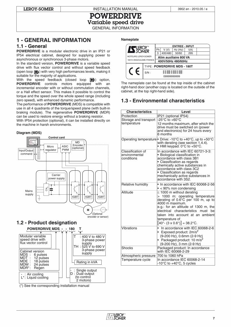
1 - GENERAL INFORMATION1.1 - GeneralPOWERDRIVE is a modular electronic drive in an IP21 orIP54 electrical cabinet, designed for supplying power toasynchronous or synchronous 3-phase motors.In the standard version, POWERDRIVE is a variable speeddrive with flux vector control and without speed feedback(open loop ) with very high performances levels, making itsuitable for the majority of applications.With the speed feedback (closed loop ) option,POWERDRIVE controls motors equipped with anincremental encoder with or without commutation channels,or a Hall effect sensor. This makes it possible to control thetorque and the speed over the whole speed range (includingzero speed), with enhanced dynamic performance.The performance of POWERDRIVE (MDS) is compatible withuse in all 4 quadrants of the torque/speed plane (with built-inbraking module). The regenerative POWERDRIVE (MDR)can be used to restore energy without a braking resistor.With IP54 protection (optional), it can be installed directly onthe machine in harsh environments.
Diagram (MDS)
1.2 - Product designation
Nameplate
The nameplate can be found at the top inside of the cabinetright-hand door (another copy is located on the outside of thecabinet, at the top right-hand side).
1.3 - Environmental characteristics
Micro regulatorInput/Output
command
Mains supply
ASIC PWM
Carrier power supply
(Optional encoder or sensor)
MD Encoder(optional)
Control card
M
IGBT IGBT IGBT
POWERDRIVE MDS - - 180 T
Cabinet versionMDS : 6 pulsesMDT : 12 pulsesMDE : 18 pulsesMDW : 24 pulsesMDR* : Regen
Rating in kVA
T : 400 V to 480 V 3-phase power supplyTH : 525 V to 690 V 3-phase power supply
- : Single outputD : Dual output (to control 2 motors)
Modular variablespeed drive withflux vector control
(*) See the corresponding installation manual
- : Air coolingL* : Liquid cooling
Characteristics LevelProtection IP21 (optional IP54)Storage and transport temperature
-25°C to +60°C12 months maximum, after which the drive must be switched on (power and electronics) for 24 hours every 6 months
Operating temperature • Drive: -10°C to +40°C, up to +50°C with derating (see section 1.4.4).• HMI keypad: 0°C to +50°C.
Classification of environmental conditions
In accordance with IEC 60721-3-3:• Biological classification in accordance with class 3B1• Classification as regards chemically active substances in accordance with class 3C2• Classification as regards mechanically active substances in accordance with 3S2.
Relative humidity • In accordance with IEC 60068-2-56• < 90% non condensing
Altitude 1000 m without derating> 1000 m: operating temperaturederating of 0.6°C per 100 m, up to4000 m maximum. e.g.: for an altitude of 1300 m, theelectrical characteristics must betaken into account at an ambienttemperature of [40°- (3 x 0.6°)] = 38.2°C.
Vibrations • In accordance with IEC 60068-2-6• Exposed product: 2m/s2
(9-200 Hz), 0.6mm (2-9 Hz)• Packaged product: 10 m/s2
(9-200 Hz), 3 mm (2-9 Hz)Shocks Packaged product: In accordance
with IEC 60068-2-29Atmospheric pressure 700 to 1060 hPaTemperature cycle In accordance IEC 60068-2-14
-10°C to +40°C, 5 cycles
MOTEURS LEROY-SOMER
16015 ANGOULEME FRANCE
ENTREE - INPUT
Alim auxiliaire 800 VA400V/50Hz 480/60Hz
POWERDRIVE MDS - 180T
Ph V (V) Hz (Hz) I(A) 3 400/480 50/60 295
TYPE :
S/N : 09999999999
8
INSTALLATION MANUAL
POWERDRIVEVariable speed drive
GENERAL INFORMATION
LEROY-SOMER 3902 en - 2010.05 / e
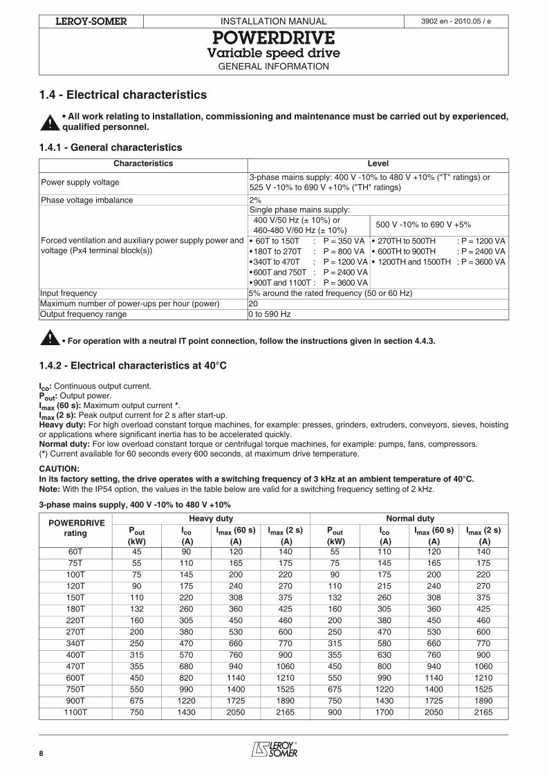
1.4 - Electrical characteristics
• All work relating to installation, commissioning and maintenance must be carried out by experienced,qualified personnel.
1.4.1 - General characteristics
• For operation with a neutral IT point connection, follow the instructions given in section 4.4.3.
1.4.2 - Electrical characteristics at 40°C
Ico: Continuous output current.Pout: Output power.Imax (60 s): Maximum output current *.Imax (2 s): Peak output current for 2 s after start-up.Heavy duty: For high overload constant torque machines, for example: presses, grinders, extruders, conveyors, sieves, hoistingor applications where significant inertia has to be accelerated quickly.Normal duty: For low overload constant torque or centrifugal torque machines, for example: pumps, fans, compressors.(*) Current available for 60 seconds every 600 seconds, at maximum drive temperature.
CAUTION:In its factory setting, the drive operates with a switching frequency of 3 kHz at an ambient temperature of 40°C.Note: With the IP54 option, the values in the table below are valid for a switching frequency setting of 2 kHz.
3-phase mains supply, 400 V -10% to 480 V +10%
Characteristics Level
Power supply voltage3-phase mains supply: 400 V -10% to 480 V +10% ("T" ratings) or 525 V -10% to 690 V +10% ("TH" ratings)
Phase voltage imbalance 2%
Forced ventilation and auxiliary power supply power and voltage (Px4 terminal block(s))
Single phase mains supply:400 V/50 Hz (± 10%) or460-480 V/60 Hz (± 10%)
500 V -10% to 690 V +5%
• 60T to 150T : P = 350 VA • 270TH to 500TH : P = 1200 VA•180T to 270T : P = 800 VA • 600TH to 900TH : P = 2400 VA•340T to 470T : P = 1200 VA • 1200TH and 1500TH : P = 3600 VA•600T and 750T : P = 2400 VA•900T and 1100T : P = 3600 VA
Input frequency 5% around the rated frequency (50 or 60 Hz)Maximum number of power-ups per hour (power) 20Output frequency range 0 to 590 Hz
POWERDRIVE rating
Heavy duty Normal dutyPout Ico Imax (60 s) Imax (2 s) Pout Ico Imax (60 s) Imax (2 s)(kW) (A) (A) (A) (kW) (A) (A) (A)
60T 45 90 120 140 55 110 120 14075T 55 110 165 175 75 145 165 175100T 75 145 200 220 90 175 200 220120T 90 175 240 270 110 215 240 270150T 110 220 308 375 132 260 308 375180T 132 260 360 425 160 305 360 425220T 160 305 450 460 200 380 450 460270T 200 380 530 600 250 470 530 600340T 250 470 660 770 315 580 660 770400T 315 570 760 900 355 630 760 900470T 355 680 940 1060 450 800 940 1060600T 450 820 1140 1210 550 990 1140 1210750T 550 990 1400 1525 675 1220 1400 1525900T 675 1220 1725 1890 750 1430 1725 1890
1100T 750 1430 2050 2165 900 1700 2050 2165
9
INSTALLATION MANUAL
POWERDRIVEVariable speed drive
GENERAL INFORMATION
LEROY-SOMER 3902 en - 2010.05 / e
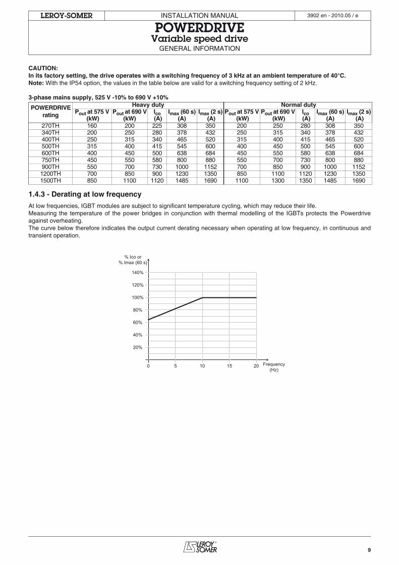
CAUTION:In its factory setting, the drive operates with a switching frequency of 3 kHz at an ambient temperature of 40°C.Note: With the IP54 option, the values in the table below are valid for a switching frequency setting of 2 kHz.
3-phase mains supply, 525 V -10% to 690 V +10%
1.4.3 - Derating at low frequency
At low frequencies, IGBT modules are subject to significant temperature cycling, which may reduce their life.Measuring the temperature of the power bridges in conjunction with thermal modelling of the IGBTs protects the Powerdriveagainst overheating.The curve below therefore indicates the output current derating necessary when operating at low frequency, in continuous andtransient operation.
POWERDRIVE rating
Heavy duty Normal dutyPout at 575 V Pout at 690 V Ico Imax (60 s) Imax (2 s) Pout at 575 V Pout at 690 V Ico Imax (60 s) Imax (2 s)
(kW) (kW) (A) (A) (A) (kW) (kW) (A) (A) (A)270TH 160 200 225 308 350 200 250 280 308 350340TH 200 250 280 378 432 250 315 340 378 432400TH 250 315 340 465 520 315 400 415 465 520500TH 315 400 415 545 600 400 450 500 545 600600TH 400 450 500 638 684 450 550 580 638 684750TH 450 550 580 800 880 550 700 730 800 880900TH 550 700 730 1000 1152 700 850 900 1000 11521200TH 700 850 900 1230 1350 850 1100 1120 1230 13501500TH 850 1100 1120 1485 1690 1100 1300 1350 1485 1690
0 5 10 15 20 Frequency(Hz)
% Ico or% Imax (60 s)
20%
40%
60%
80%
100%
120%
140%
10
INSTALLATION MANUAL
POWERDRIVEVariable speed drive
GENERAL INFORMATION
LEROY-SOMER 3902 en - 2010.05 / e
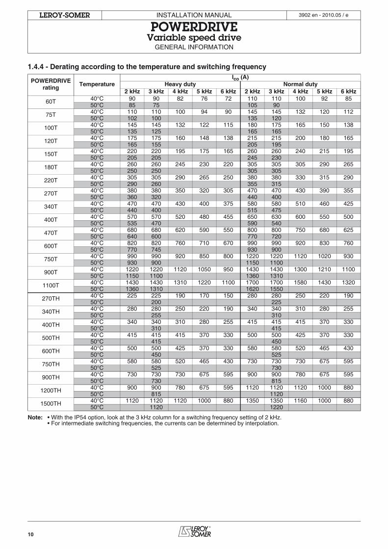
1.4.4 - Derating according to the temperature and switching frequency
Note: • With the IP54 option, look at the 3 kHz column for a switching frequency setting of 2 kHz.• For intermediate switching frequencies, the currents can be determined by interpolation.
POWERDRIVE rating Temperature
Ico (A)Heavy duty Normal duty
2 kHz 3 kHz 4 kHz 5 kHz 6 kHz 2 kHz 3 kHz 4 kHz 5 kHz 6 kHz
60T 40°C 90 90 82 76 72 110 110 100 92 8550°C 85 75 105 90
75T 40°C 110 110 100 94 90 145 145 132 120 11250°C 102 100 135 120
100T 40°C 145 145 132 122 115 180 175 165 150 13850°C 135 125 165 165
120T 40°C 175 175 160 148 138 215 215 200 180 16550°C 165 155 205 195
150T 40°C 220 220 195 175 165 260 260 240 215 19550°C 205 205 245 230
180T 40°C 260 260 245 230 220 305 305 305 290 26550°C 250 250 305 305
220T 40°C 305 305 290 265 250 380 380 330 315 29050°C 290 260 355 315
270T 40°C 380 380 350 320 305 470 470 430 390 35550°C 360 320 440 400
340T 40°C 470 470 430 400 375 580 580 510 460 42550°C 440 400 515 475
400T 40°C 570 570 520 480 455 650 630 600 550 50050°C 535 470 590 540
470T 40°C 680 680 620 590 550 800 800 750 680 62550°C 640 600 770 720
600T 40°C 820 820 760 710 670 990 990 920 830 76050°C 770 745 930 900
750T 40°C 990 990 920 850 800 1220 1220 1120 1020 93050°C 930 900 1150 1100
900T 40°C 1220 1220 1120 1050 950 1430 1430 1300 1210 110050°C 1150 1100 1360 1310
1100T 40°C 1430 1430 1310 1220 1100 1700 1700 1580 1430 132050°C 1360 1310 1620 1550
270TH 40°C 225 225 190 170 150 280 280 250 220 19050°C 200 225
340TH 40°C 280 280 250 220 190 340 340 310 280 25550°C 255 310
400TH 40°C 340 340 310 280 255 415 415 415 370 33050°C 310 415
500TH 40°C 415 415 415 370 330 500 500 425 370 33050°C 415 450
600TH 40°C 500 500 425 370 330 580 580 520 465 43050°C 450 525
750TH 40°C 580 580 520 465 430 730 730 730 675 59550°C 525 730
900TH 40°C 730 730 730 675 595 900 900 780 675 59550°C 730 815
1200TH 40°C 900 900 780 675 595 1120 1120 1120 1000 88050°C 815 1120
1500TH 40°C 1120 1120 1120 1000 880 1350 1350 1160 1000 88050°C 1120 1220
11
INSTALLATION MANUAL
POWERDRIVEVariable speed driveMECHANICAL INSTALLATION
LEROY-SOMER 3902 en - 2010.05 / e
2 - MECHANICAL INSTALLATION• It is the responsibility of the owner or user of the POWERDRIVE to ensure that the installation, operation andmaintenance of the drive and its options comply with legislation relating to the safety of personnel and equipment
and with the current regulations of the country of use.The drive must not be installed in hazardous areas unless it is in an appropriate enclosure. In this case the installationmust be approved.
• In atmospheres where condensation may form, install a heating system which operates when the drive is not inuse and is switched off when the drive is in use. It is advisable to control the heating system automatically.
2.1 - Checks on receipt
• Check that the cabinet has been transported vertically, otherwise, it may be damaged.
Before installing the POWERDRIVE, check that:- The drive has not been damaged during transport.- The information on the nameplate is compatible with the power supply.
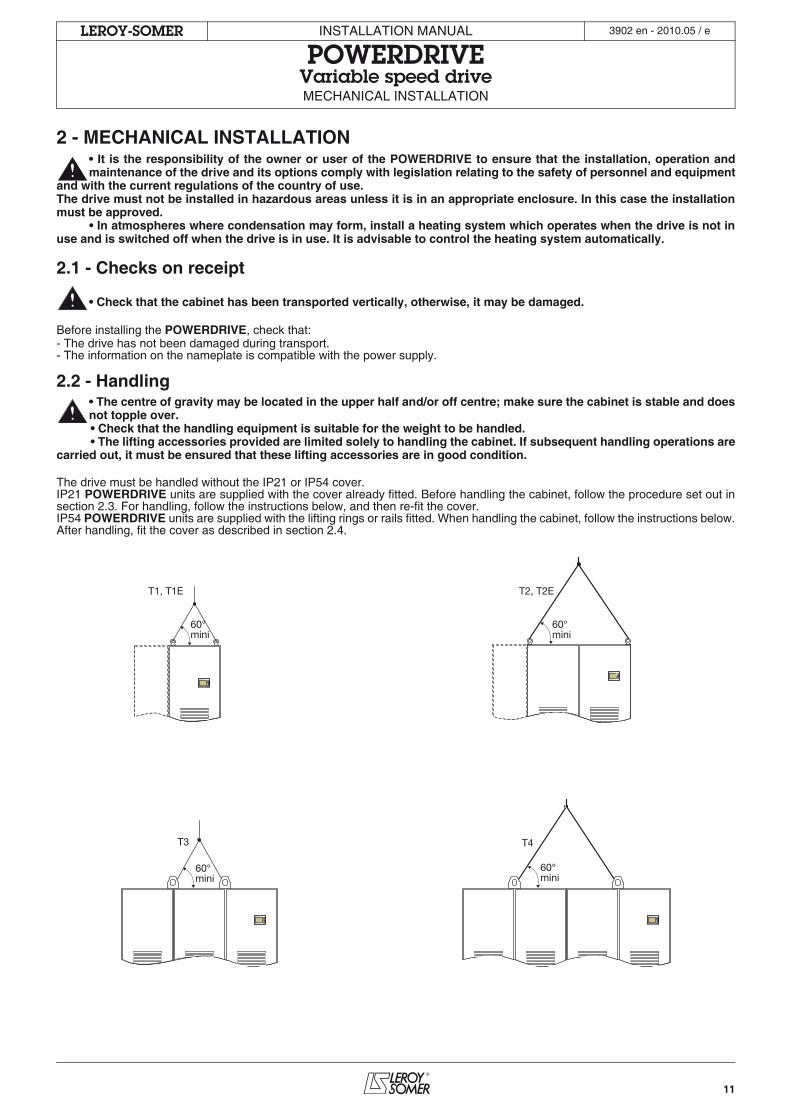
2.2 - Handling• The centre of gravity may be located in the upper half and/or off centre; make sure the cabinet is stable and doesnot topple over.• Check that the handling equipment is suitable for the weight to be handled.• The lifting accessories provided are limited solely to handling the cabinet. If subsequent handling operations are
carried out, it must be ensured that these lifting accessories are in good condition.
The drive must be handled without the IP21 or IP54 cover.IP21 POWERDRIVE units are supplied with the cover already fitted. Before handling the cabinet, follow the procedure set out insection 2.3. For handling, follow the instructions below, and then re-fit the cover.IP54 POWERDRIVE units are supplied with the lifting rings or rails fitted. When handling the cabinet, follow the instructions below.After handling, fit the cover as described in section 2.4.
T1, T1E T2, T2E
T4 T3
60°mini
60°mini
60°mini
60°mini
12
INSTALLATION MANUAL
POWERDRIVEVariable speed driveMECHANICAL INSTALLATION
LEROY-SOMER 3902 en - 2010.05 / e
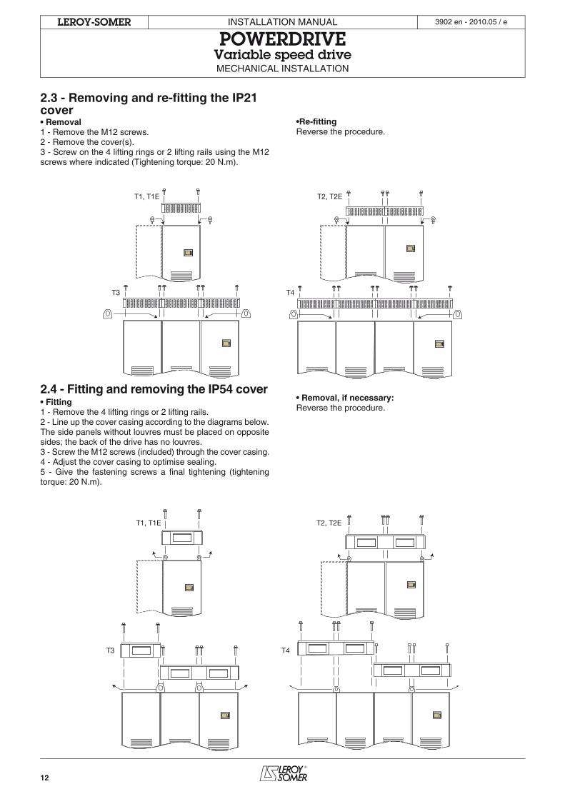
2.3 - Removing and re-fitting the IP21 cover• Removal1 - Remove the M12 screws.2 - Remove the cover(s).3 - Screw on the 4 lifting rings or 2 lifting rails using the M12screws where indicated (Tightening torque: 20 N.m).
•Re-fittingReverse the procedure.
2.4 - Fitting and removing the IP54 cover• Fitting1 - Remove the 4 lifting rings or 2 lifting rails.2 - Line up the cover casing according to the diagrams below.The side panels without louvres must be placed on oppositesides; the back of the drive has no louvres.3 - Screw the M12 screws (included) through the cover casing.4 - Adjust the cover casing to optimise sealing. 5 - Give the fastening screws a final tightening (tighteningtorque: 20 N.m).
• Removal, if necessary:Reverse the procedure.
T1, T1E T2, T2E
T4T3
T1, T1E T2, T2E
T4T3

13
INSTALLATION MANUAL
POWERDRIVEVariable speed driveMECHANICAL INSTALLATION
LEROY-SOMER 3902 en - 2010.05 / e
2.5 - Installation recommendations
• The drives must be installed away from conducting dust, corrosive gas, dripping water and any source ofcondensation. Prevent access by inexperienced personnel.• After connecting the power, reposition the cable bush plates, which may be done at the back of the cabinet, to
prevent the entry of foreign bodies.
Ensure that hot air is not being recycled via the air inlets by leaving sufficient free space above the POWERDRIVE or providing ameans of evacuating the hot air expelled by the product. If necessary, add a suction hood.Never obstruct the drive ventilation grilles; the air intake filters must be cleaned and changed regularly.
14
INSTALLATION MANUAL
POWERDRIVEVariable speed driveMECHANICAL INSTALLATION
LEROY-SOMER 3902 en - 2010.05 / e
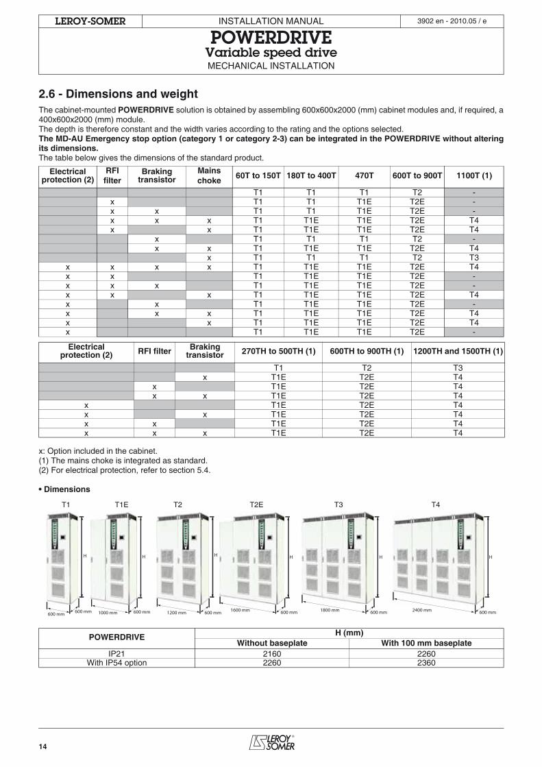
2.6 - Dimensions and weightThe cabinet-mounted POWERDRIVE solution is obtained by assembling 600x600x2000 (mm) cabinet modules and, if required, a400x600x2000 (mm) module.The depth is therefore constant and the width varies according to the rating and the options selected.The MD-AU Emergency stop option (category 1 or category 2-3) can be integrated in the POWERDRIVE without alteringits dimensions.The table below gives the dimensions of the standard product.
x: Option included in the cabinet.(1) The mains choke is integrated as standard.(2) For electrical protection, refer to section 5.4.
• Dimensions
Electrical protection (2)
RFI filter
Braking transistor
Mains choke
60T to 150T 180T to 400T 470T 600T to 900T 1100T (1)
T1 T1 T1 T2 -x T1 T1 T1E T2E -x x T1 T1 T1E T2E -x x x T1 T1E T1E T2E T4x x T1 T1E T1E T2E T4
x T1 T1 T1 T2 -x x T1 T1E T1E T2E T4
x T1 T1 T1 T2 T3x x x x T1 T1E T1E T2E T4x x T1 T1E T1E T2E -x x x T1 T1E T1E T2E -x x x T1 T1E T1E T2E T4x x T1 T1E T1E T2E -x x x T1 T1E T1E T2E T4x x T1 T1E T1E T2E T4x T1 T1E T1E T2E -
Electrical protection (2) RFI filter Braking
transistor 270TH to 500TH (1) 600TH to 900TH (1) 1200TH and 1500TH (1)
T1 T2 T3x T1E T2E T4
x T1E T2E T4x x T1E T2E T4
x T1E T2E T4x x T1E T2E T4x x T1E T2E T4x x x T1E T2E T4
POWERDRIVE H (mm)Without baseplate With 100 mm baseplate
IP21 2160 2260With IP54 option 2260 2360
H
600 mm 600 mm
T1 T1E T2 T2E T3 T4
H
1200 mm 600 mm1000 mm 600 mm
H
1600 mm 600 mm
H
1800 mm 600 mm
H
2400 mm 600 mm
H
15
INSTALLATION MANUAL
POWERDRIVEVariable speed driveMECHANICAL INSTALLATION
LEROY-SOMER 3902 en - 2010.05 / e
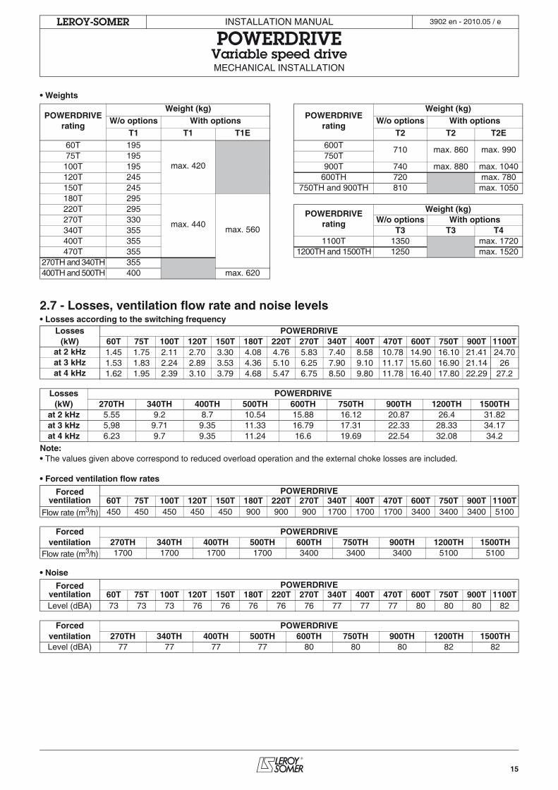
• Weights
2.7 - Losses, ventilation flow rate and noise levels• Losses according to the switching frequency
Note:• The values given above correspond to reduced overload operation and the external choke losses are included.
• Forced ventilation flow rates
• Noise
POWERDRIVE rating
Weight (kg)POWERDRIVE
rating
Weight (kg)W/o options With options W/o options With options
T1 T1 T1E T2 T2 T2E60T 195
max. 420
600T 710 max. 860 max. 99075T 195 750T100T 195 900T 740 max. 880 max. 1040120T 245 600TH 720 max. 780150T 245 750TH and 900TH 810 max. 1050180T 295
max. 440max. 560
220T 295 POWERDRIVE rating
Weight (kg)270T 330 W/o options With options340T 355 T3 T3 T4400T 355 1100T 1350 max. 1720470T 355 1200TH and 1500TH 1250 max. 1520
270TH and 340TH 355400TH and 500TH 400 max. 620
Losses POWERDRIVE(kW) 60T 75T 100T 120T 150T 180T 220T 270T 340T 400T 470T 600T 750T 900T 1100T
at 2 kHz 1.45 1.75 2.11 2.70 3.30 4.08 4.76 5.83 7.40 8.58 10.78 14.90 16.10 21.41 24.70at 3 kHz 1.53 1.83 2.24 2.89 3.53 4.36 5.10 6.25 7.90 9.10 11.17 15.60 16.90 21.14 26at 4 kHz 1.62 1.95 2.39 3.10 3.79 4.68 5.47 6.75 8.50 9.80 11.78 16.40 17.80 22.29 27.2
Losses POWERDRIVE(kW) 270TH 340TH 400TH 500TH 600TH 750TH 900TH 1200TH 1500TH
at 2 kHz 5.55 9.2 8.7 10.54 15.88 16.12 20.87 26.4 31.82at 3 kHz 5,98 9.71 9.35 11.33 16.79 17.31 22.33 28.33 34.17at 4 kHz 6.23 9.7 9.35 11.24 16.6 19.69 22.54 32.08 34.2
Forced ventilation
POWERDRIVE60T 75T 100T 120T 150T 180T 220T 270T 340T 400T 470T 600T 750T 900T 1100T
Flow rate (m3/h) 450 450 450 450 450 900 900 900 1700 1700 1700 3400 3400 3400 5100
Forced POWERDRIVEventilation 270TH 340TH 400TH 500TH 600TH 750TH 900TH 1200TH 1500TH
Flow rate (m3/h) 1700 1700 1700 1700 3400 3400 3400 5100 5100
Forced ventilation
POWERDRIVE60T 75T 100T 120T 150T 180T 220T 270T 340T 400T 470T 600T 750T 900T 1100T
Level (dBA) 73 73 73 76 76 76 76 76 77 77 77 80 80 80 82
Forced POWERDRIVEventilation 270TH 340TH 400TH 500TH 600TH 750TH 900TH 1200TH 1500THLevel (dBA) 77 77 77 77 80 80 80 82 82
16
INSTALLATION MANUAL
POWERDRIVEVariable speed drive
CONNECTIONS
LEROY-SOMER 3902 en - 2010.05 / e
3 - CONNECTIONS• All connection work must be performed inaccordance with the laws in force in the country in
which the drive is installed. This includes earthing toensure that no directly accessible part of the drive canbe at the mains voltage or any other voltage which maybe dangerous.
• The voltages on the cables or connections of themains supply, the motor, the braking resistor or the filtermay cause fatal electric shocks. Contact must beavoided under all circumstances.
• The drive must be supplied via a circuit-breakingdevice so that it can be powered down safely.
• The drive power supply must be protected againstoverloads and short-circuits.
• The drive stop function does not protect againsthigh voltages on the terminal blocks.
• Ensure that the DC bus voltage is below 40 Vbefore carrying out any work (the control card power-onindicator LED must be off, see section 5.5.1).
• Check that the voltage and current of the drive,the motor and the mains supply are compatible.
• After the drive has been operating, the heatsinkmay be very hot; avoid touching it (70°C).
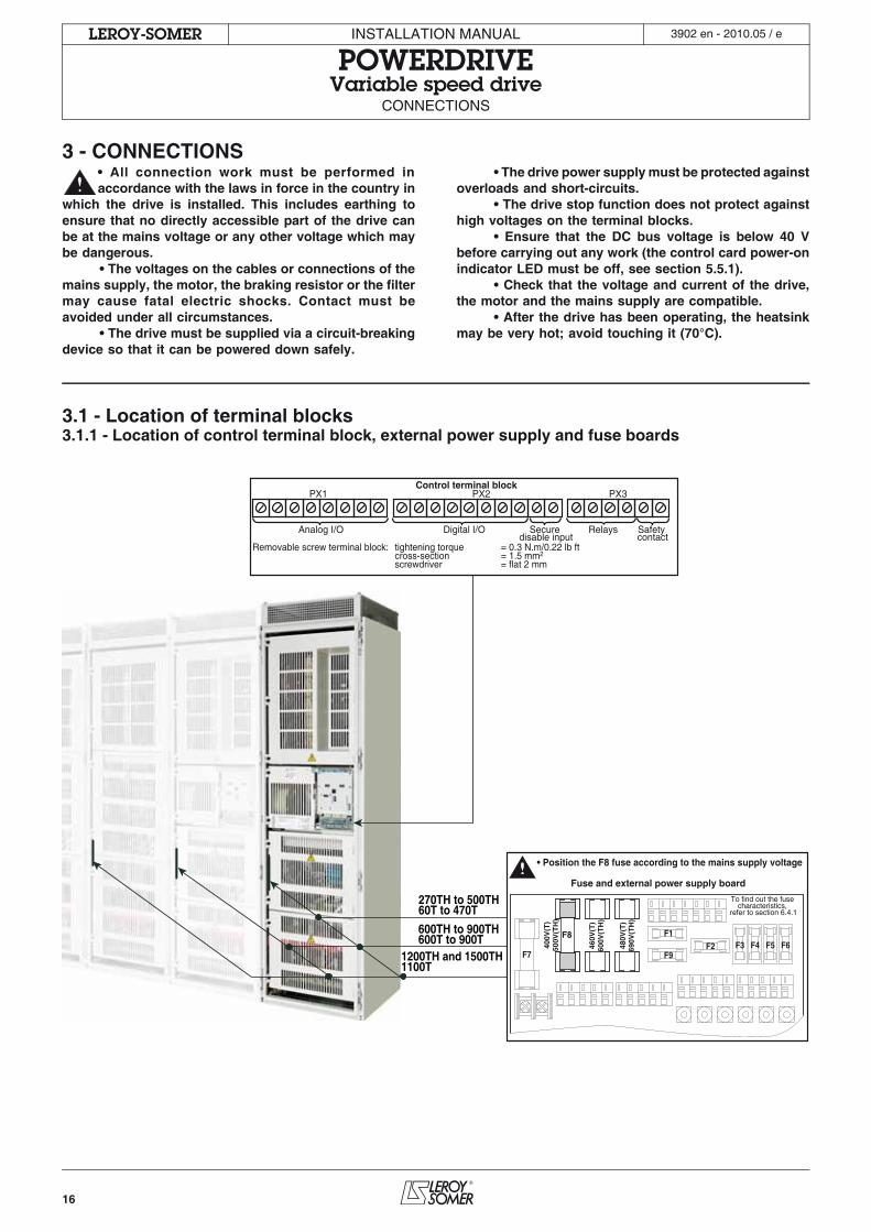
3.1 - Location of terminal blocks3.1.1 - Location of control terminal block, external power supply and fuse boards
600TH to 900TH600T to 900T
1200TH and 1500TH1100T
270TH to 500TH60T to 470T
Control terminal block
Removable screw terminal block: tightening torque = 0.3 N.m/0.22 lb ft cross-section = 1.5 mm2
screwdriver = flat 2 mm
Analog I/O Digital I/O Relays Safety contact
Secure disable input
PX1 PX2 PX3
F1F2 F3 F4 F5 F6
F9F7
460V
(T)
600V
(TH
)
480V
(T)
690V
(TH
)
To find out the fuse characteristics,
refer to section 6.4.1
• Position the F8 fuse according to the mains supply voltage
Fuse and external power supply board
F8
400V
(T)
500V
(TH
)
17
INSTALLATION MANUAL
POWERDRIVEVariable speed drive
CONNECTIONS
LEROY-SOMER 3902 en - 2010.05 / e
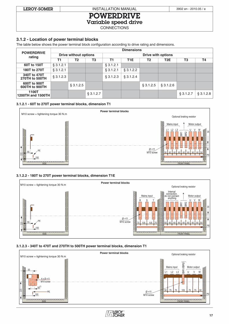
3.1.2 - Location of power terminal blocksThe table below shows the power terminal block configuration according to drive rating and dimensions.
3.1.2.1 - 60T to 270T power terminal blocks, dimension T1
3.1.2.2 - 180T to 270T power terminal blocks, dimension T1E
3.1.2.3 - 340T to 470T and 270TH to 500TH power terminal blocks, dimension T1
POWERDRIVE rating
DimensionsDrive without options Drive with options
T1 T2 T3 T1 T1E T2 T2E T3 T460T to 150T § 3.1.2.1 § 3.1.2.1
180T to 270T § 3.1.2.1 § 3.1.2.1 § 3.1.2.2
340T to 470T270TH to 500TH § 3.1.2.3 § 3.1.2.3 § 3.1.2.4
600T to 900T600TH to 900TH § 3.1.2.5 § 3.1.2.5 § 3.1.2.6
1100T1200TH and 1500TH § 3.1.2.7 § 3.1.2.7 § 3.1.2.8
Ø =11M10 screw
Mains input Motor output
Optional braking resistorM10 screw = tightening torque 30 N.m
55
100
50 5060 60 60 60 60 60 60
BR1
BR2
U V WL1 L2 L3
50
PE
PE
FRONT PANELSIDE
Power terminal blocks
220
Ø =11 M10 screw
Mains input Motor output
Optional braking resistor
Internal connection,
do not connect anything
M10 screw = tightening torque 30 N.m
55
100
50 50 60 60 60 60 60 60 60
BR1
BR2
U V W
50
PE
PE
FRONT PANEL SIDE
70 70 105 105
R S T
Power terminal blocks
220
BR
1/B
R2
Mains input Motor output
Optional braking resistorPower terminal blocksM10 screw = tightening torque 30 N.m
93
4 x Ø =11M10 screw
5050 5075 75 105 75 75
U V WL1 L2 L3
PE100PE
FRONT PANELSIDE
Ø =11M10 screw
220
18
INSTALLATION MANUAL
POWERDRIVEVariable speed drive
CONNECTIONS
LEROY-SOMER 3902 en - 2010.05 / e
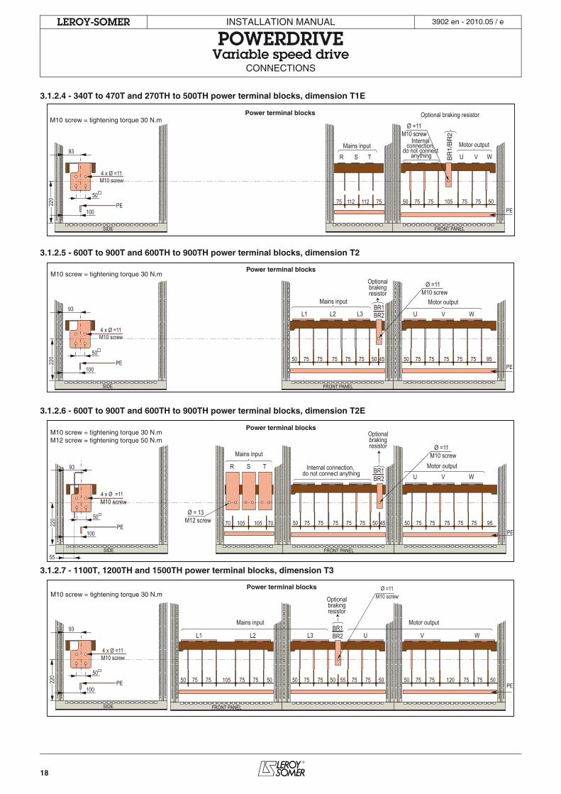
3.1.2.4 - 340T to 470T and 270TH to 500TH power terminal blocks, dimension T1E
3.1.2.5 - 600T to 900T and 600TH to 900TH power terminal blocks, dimension T2
3.1.2.6 - 600T to 900T and 600TH to 900TH power terminal blocks, dimension T2E
3.1.2.7 - 1100T, 1200TH and 1500TH power terminal blocks, dimension T3
Power terminal blocksM10 screw = tightening torque 30 N.m
4 x Ø =11 M10 screw
220
BR
1/B
R2
Motor output
Optional braking resistor
U V W Mains input
R S T 93
50 50 50 75 75 105 75 75
PE 100 PE
FRONT PANEL SIDE
75 75 112 112
Ø =11M10 screw
Internal connection,
do not connect anything
Power terminal blocksM10 screw = tightening torque 30 N.m
L1 L2 L3
Mains input Motor output
Optionalbrakingresistor
U V WBR1BR2
4 x Ø =11M10 screw
Ø =11 M10 screw
220 50 75 75 75 75 75 50 45 50 75 75 75 75 75 95
PE
FRONT PANEL
93
50
100PE
SIDE
Power terminal blocksM10 screw = tightening torque 30 N.mM12 screw = tightening torque 50 N.m
4 x Ø =11 M10 screw
Mains input
Motor output
Optional braking resistor
Internal connection, do not connect anything
R S T U V W
BR1 BR2
220
55
70 70 105 105 50 75 75 75 75 75 50 45 50 75 75 75 75 75 95 PE
FRONT PANEL
93
50
100 PE
SIDE
Ø = 13 M12 screw
Ø =11 M10 screw
Power terminal blocksM10 screw = tightening torque 30 N.m
50 75 75 105 75 75 50 50 75 75 55 75 75
L1 L2 L3
50 50 50 75 75 120 75 75
U V W
PE
FRONT PANEL
50
BR1 BR2
93
50
100 PE
SIDE
Motor output Mains input
Optionalbrakingresistor
4 x Ø =11 M10 screw
Ø =11M10 screw
220
19
INSTALLATION MANUAL
POWERDRIVEVariable speed drive
CONNECTIONS
LEROY-SOMER 3902 en - 2010.05 / e
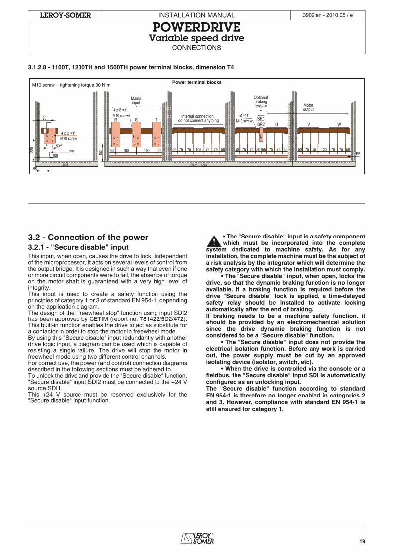
3.1.2.8 - 1100T, 1200TH and 1500TH power terminal blocks, dimension T4
3.2 - Connection of the power3.2.1 - "Secure disable" inputThis input, when open, causes the drive to lock. Independentof the microprocessor, it acts on several levels of control fromthe output bridge. It is designed in such a way that even if oneor more circuit components were to fail, the absence of torqueon the motor shaft is guaranteed with a very high level ofintegrity.This input is used to create a safety function using theprinciples of category 1 or 3 of standard EN 954-1, dependingon the application diagram.The design of the "freewheel stop" function using input SDI2has been approved by CETIM (report no. 781422/5D2/472).This built-in function enables the drive to act as substitute fora contactor in order to stop the motor in freewheel mode.By using this "Secure disable" input redundantly with anotherdrive logic input, a diagram can be used which is capable ofresisting a single failure. The drive will stop the motor infreewheel mode using two different control channels.For correct use, the power (and control) connection diagramsdescribed in the following sections must be adhered to.To unlock the drive and provide the "Secure disable" function,"Secure disable" input SDI2 must be connected to the +24 Vsource SDI1.This +24 V source must be reserved exclusively for the"Secure disable" input function.
• The "Secure disable" input is a safety componentwhich must be incorporated into the complete
system dedicated to machine safety. As for anyinstallation, the complete machine must be the subject ofa risk analysis by the integrator which will determine thesafety category with which the installation must comply.
• The "Secure disable" input, when open, locks thedrive, so that the dynamic braking function is no longeravailable. If a braking function is required before thedrive "Secure disable" lock is applied, a time-delayedsafety relay should be installed to activate lockingautomatically after the end of braking. If braking needs to be a machine safety function, itshould be provided by an electromechanical solutionsince the drive dynamic braking function is notconsidered to be a "Secure disable" function.
• The "Secure disable" input does not provide theelectrical isolation function. Before any work is carriedout, the power supply must be cut by an approvedisolating device (isolator, switch, etc).
• When the drive is controlled via the console or afieldbus, the "Secure disable" input SDI is automaticallyconfigured as an unlocking input.The "Secure disable" function according to standardEN 954-1 is therefore no longer enabled in categories 2and 3. However, compliance with standard EN 954-1 isstill ensured for category 1.
M10 screw = tightening torque 30 N.mPower terminal blocks
55
50 75 75 105 75 75 50 50 75 75 55 75 75 50 50 50 75 75 120 75 75
U V W
PE
FRONT PANEL
65 190 190 65 50
BR1 BR2
93
50
100 PE
SIDE
220
150
R S T
Motoroutput
Mainsinput
Optionalbrakingresistor
4 x Ø =11 M10 screw
Ø =11 M10 screw
4 x Ø =11 M10 screw Internal connection,
do not connect anything
20
INSTALLATION MANUAL
POWERDRIVEVariable speed drive
CONNECTIONS
LEROY-SOMER 3902 en - 2010.05 / e
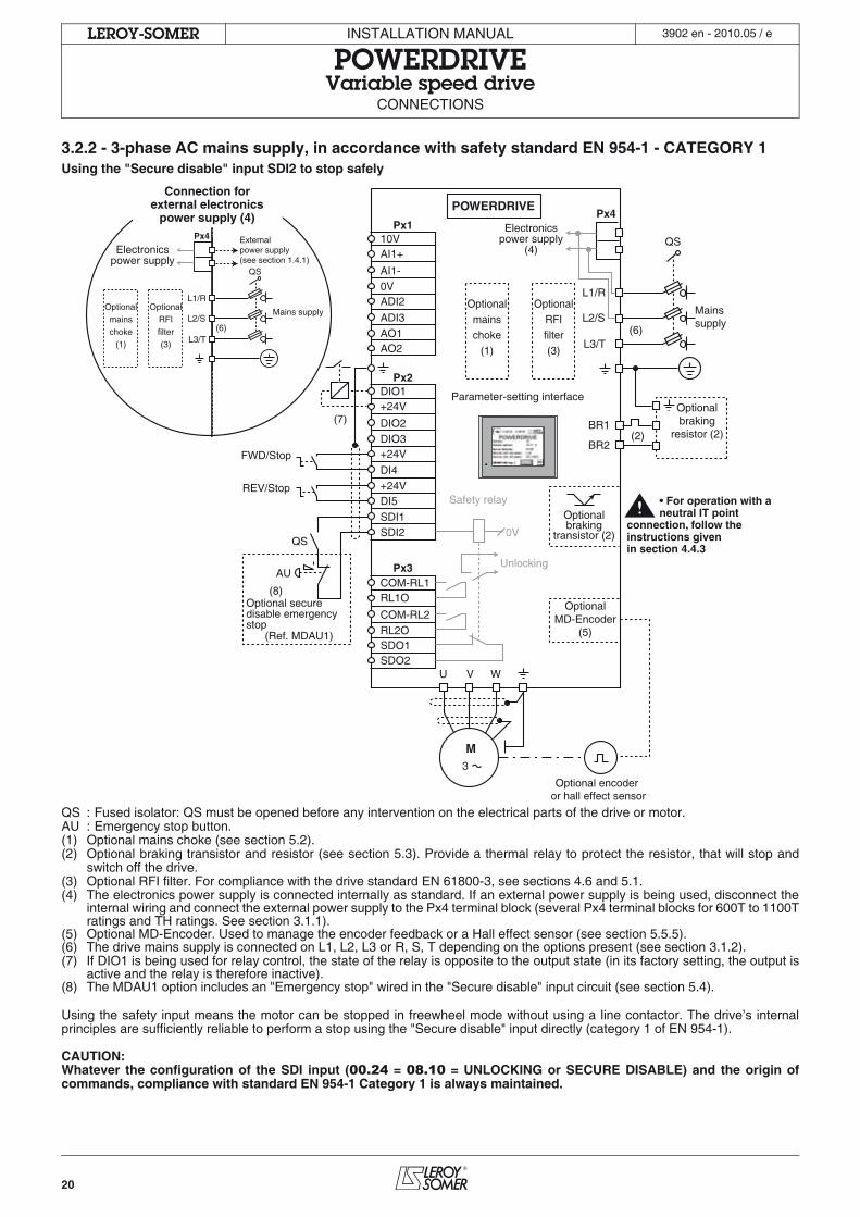
3.2.2 - 3-phase AC mains supply, in accordance with safety standard EN 954-1 - CATEGORY 1Using the "Secure disable" input SDI2 to stop safely
QS : Fused isolator: QS must be opened before any intervention on the electrical parts of the drive or motor.AU : Emergency stop button.(1) Optional mains choke (see section 5.2).(2) Optional braking transistor and resistor (see section 5.3). Provide a thermal relay to protect the resistor, that will stop and
switch off the drive.(3) Optional RFI filter. For compliance with the drive standard EN 61800-3, see sections 4.6 and 5.1.(4) The electronics power supply is connected internally as standard. If an external power supply is being used, disconnect the
internal wiring and connect the external power supply to the Px4 terminal block (several Px4 terminal blocks for 600T to 1100Tratings and TH ratings. See section 3.1.1).
(5) Optional MD-Encoder. Used to manage the encoder feedback or a Hall effect sensor (see section 5.5.5).(6) The drive mains supply is connected on L1, L2, L3 or R, S, T depending on the options present (see section 3.1.2).(7) If DIO1 is being used for relay control, the state of the relay is opposite to the output state (in its factory setting, the output is
active and the relay is therefore inactive).(8) The MDAU1 option includes an "Emergency stop" wired in the "Secure disable" input circuit (see section 5.4).
Using the safety input means the motor can be stopped in freewheel mode without using a line contactor. The drive’s internalprinciples are sufficiently reliable to perform a stop using the "Secure disable" input directly (category 1 of EN 954-1).
CAUTION:Whatever the configuration of the SDI input (00.24 = 08.10 = UNLOCKING or SECURE DISABLE) and the origin ofcommands, compliance with standard EN 954-1 Category 1 is always maintained.
AU
QS
FWD/Stop
REV/Stop
(7)
Optional securedisable emergencystop
(Ref. MDAU1)
L3/T
L2/S
L1/R
External power supply (see section 1.4.1)
QS
Optionalmainschoke
(1)
(6)
(8)
Px4
Mains supplyOptional
RFIfilter(3)
Connection for external electronics
power supply (4)
U V W
POWERDRIVE
Px1 10VAI1+
AI1-0VADI2
ADI3AO1AO2
Px2 DIO1+24V
DIO2DIO3+24V
DI4+24VDI5
SDI10V
Unlocking
SDI2
Px3 COM-RL1RL1O
COM-RL2RL2OSDO1SDO2
Safety relay
M 3
Optional encoder or hall effect sensor
L3/T
L2/S
L1/R
QS
Optionalbraking
resistor (2)
Optionalmainschoke
(1)
BR1(2)
(6)
BR2
Electronicspower supply
(4)Electronicspower supply
Px4
OptionalMD-Encoder
(5)
Optionalbraking
transistor (2)
Mains supply
Parameter-setting interface
OptionalRFIfilter(3)
• For operation with a neutral IT point connection, follow the instructions given in section 4.4.3
21
INSTALLATION MANUAL
POWERDRIVEVariable speed drive
CONNECTIONS
LEROY-SOMER 3902 en - 2010.05 / e
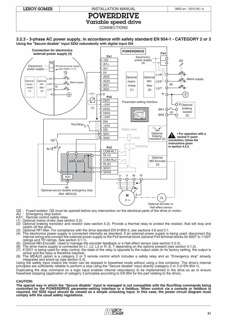
3.2.3 - 3-phase AC power supply, in accordance with safety standard EN 954-1 - CATEGORY 2 or 3Using the "Secure disable" input SDI2 redundantly with digital input DI4
QS : Fused isolator: QS must be opened before any intervention on the electrical parts of the drive or motor.AU : Emergency stop button.KA1: Remote control safety relay.(1) Optional mains choke (see section 5.2).(2) Optional braking transistor and resistor (see section 5.3). Provide a thermal relay to protect the resistor, that will stop and
switch off the drive.(3) Optional RFI filter. For compliance with the drive standard EN 61800-3, see sections 4.6 and 5.1.(4) The electronics power supply is connected internally as standard. If an external power supply is being used, disconnect the
internal wiring and connect the external power supply to the Px4 terminal block (several Px4 terminal blocks for 600T to 1100Tratings and TH ratings. See section 3.1.1).
(5) Optional MD-Encoder. Used to manage the encoder feedback or a Hall effect sensor (see section 5.5.5).(6) The drive mains supply is connected on L1, L2, L3 or R, S, T depending on the options present (see section 3.1.2).(7) If DIO1 is being used for relay control, the state of the relay is opposite to the output state (in its factory setting, the output is
active and the relay is therefore inactive).(8) The MDAU3 option is a category 2 or 3 remote control which includes a safety relay and an "Emergency stop" already
integrated and wired-up (see section 5.4).Using the safety input means the motor can be stopped in freewheel mode without using a line contactor. The drive’s internalprinciples are sufficiently reliable to perform a stop using the "Secure disable" input directly (category 2 or 3 of EN 954-1).Duplicating the stop command on a logic input enables internal redundancy to be implemented in the drive so as to ensurefreewheel stopping (application of category 3 principles according to EN 954 for the part relating to the drive).
CAUTION:The special way in which the "Secure disable" input is managed is not compatible with the Run/Stop commands beingcontrolled by the POWERDRIVE parameter-setting interface or a fieldbus. When control via a console or fieldbus isrequired, the SDI2 input should be viewed as a simple unlocking input. In this case, the power circuit diagram mustcomply with the usual safety regulations.
U V W
AU
QS
POWERDRIVE
Px110VAI1+
AI1-0VADI2
ADI3AO1AO2
Px2DIO1+24V
DIO2DIO3+24V
DI4+24VDI5
SDI10V
Unlocking
SDI2
Px3COM-RL1RL1O
COM-RL2RL2OSDO1SDO2
Safety relay
KA1
KA1
KA1
Run/Stop
M3
Optional encoder or Hall effect sensor
L3/T
L2/S
L1/R
QS
Optional braking resistor
(2)
Optional mains choke
(1)
BR1(2)
(6)
BR2
Electronics power supply
(4)
Px4
Optional MD-Encoder
(5)
Optional braking
transistor (2)
Mains supply
Parameter-setting interface
(8)Optional secure disable emergency stop
(Ref. MDAU3)
Optional RFI filter(3)L3/T
L2/S
L1/R
External power supply (see section 1.4.1)
QS
Optional mains choke
(1)
(6)
Px4
Mains supplyOptional
RFI filter(3)
Connection for electronics external power supply (4)
(7)
Electronics power supply
• For operation with a neutral IT point connection, follow the instructions given in section 4.4.3.
22
INSTALLATION MANUAL
POWERDRIVEVariable speed drive
CONNECTIONS
LEROY-SOMER 3902 en - 2010.05 / e
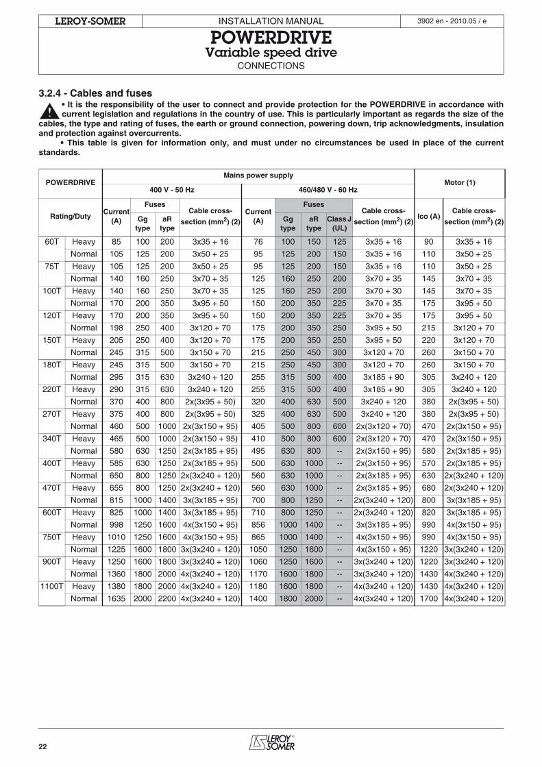
3.2.4 - Cables and fuses• It is the responsibility of the user to connect and provide protection for the POWERDRIVE in accordance withcurrent legislation and regulations in the country of use. This is particularly important as regards the size of the
cables, the type and rating of fuses, the earth or ground connection, powering down, trip acknowledgments, insulationand protection against overcurrents.
• This table is given for information only, and must under no circumstances be used in place of the currentstandards.
POWERDRIVEMains power supply
Motor (1)400 V - 50 Hz 460/480 V - 60 Hz
Rating/DutyCurrent
(A)
FusesCable cross-
section (mm2) (2)Current
(A)
FusesCable cross-
section (mm2) (2)Ico (A)
Cable cross-
section (mm2) (2)Gg type
aR type
Gg type
aR type
Class J (UL)
60T Heavy 85 100 200 3x35 + 16 76 100 150 125 3x35 + 16 90 3x35 + 16
Normal 105 125 200 3x50 + 25 95 125 200 150 3x35 + 16 110 3x50 + 25
75T Heavy 105 125 200 3x50 + 25 95 125 200 150 3x35 + 16 110 3x50 + 25
Normal 140 160 250 3x70 + 35 125 160 250 200 3x70 + 35 145 3x70 + 35
100T Heavy 140 160 250 3x70 + 35 125 160 250 200 3x70 + 30 145 3x70 + 35
Normal 170 200 350 3x95 + 50 150 200 350 225 3x70 + 35 175 3x95 + 50
120T Heavy 170 200 350 3x95 + 50 150 200 350 225 3x70 + 35 175 3x95 + 50
Normal 198 250 400 3x120 + 70 175 200 350 250 3x95 + 50 215 3x120 + 70
150T Heavy 205 250 400 3x120 + 70 175 200 350 250 3x95 + 50 220 3x120 + 70
Normal 245 315 500 3x150 + 70 215 250 450 300 3x120 + 70 260 3x150 + 70
180T Heavy 245 315 500 3x150 + 70 215 250 450 300 3x120 + 70 260 3x150 + 70
Normal 295 315 630 3x240 + 120 255 315 500 400 3x185 + 90 305 3x240 + 120
220T Heavy 290 315 630 3x240 + 120 255 315 500 400 3x185 + 90 305 3x240 + 120
Normal 370 400 800 2x(3x95 + 50) 320 400 630 500 3x240 + 120 380 2x(3x95 + 50)
270T Heavy 375 400 800 2x(3x95 + 50) 325 400 630 500 3x240 + 120 380 2x(3x95 + 50)
Normal 460 500 1000 2x(3x150 + 95) 405 500 800 600 2x(3x120 + 70) 470 2x(3x150 + 95)
340T Heavy 465 500 1000 2x(3x150 + 95) 410 500 800 600 2x(3x120 + 70) 470 2x(3x150 + 95)
Normal 580 630 1250 2x(3x185 + 95) 495 630 800 -- 2x(3x150 + 95) 580 2x(3x185 + 95)
400T Heavy 585 630 1250 2x(3x185 + 95) 500 630 1000 -- 2x(3x150 + 95) 570 2x(3x185 + 95)
Normal 650 800 1250 2x(3x240 + 120) 560 630 1000 -- 2x(3x185 + 95) 630 2x(3x240 + 120)
470T Heavy 655 800 1250 2x(3x240 + 120) 560 630 1000 -- 2x(3x185 + 95) 680 2x(3x240 + 120)
Normal 815 1000 1400 3x(3x185 + 95) 700 800 1250 -- 2x(3x240 + 120) 800 3x(3x185 + 95)
600T Heavy 825 1000 1400 3x(3x185 + 95) 710 800 1250 -- 2x(3x240 + 120) 820 3x(3x185 + 95)
Normal 998 1250 1600 4x(3x150 + 95) 856 1000 1400 -- 3x(3x185 + 95) 990 4x(3x150 + 95)
750T Heavy 1010 1250 1600 4x(3x150 + 95) 865 1000 1400 -- 4x(3x150 + 95) 990 4x(3x150 + 95)
Normal 1225 1600 1800 3x(3x240 + 120) 1050 1250 1600 -- 4x(3x150 + 95) 1220 3x(3x240 + 120)
900T Heavy 1250 1600 1800 3x(3x240 + 120) 1060 1250 1600 -- 3x(3x240 + 120) 1220 3x(3x240 + 120)
Normal 1360 1800 2000 4x(3x240 + 120) 1170 1600 1800 -- 3x(3x240 + 120) 1430 4x(3x240 + 120)
1100T Heavy 1380 1800 2000 4x(3x240 + 120) 1180 1600 1800 -- 4x(3x240 + 120) 1430 4x(3x240 + 120)
Normal 1635 2000 2200 4x(3x240 + 120) 1400 1800 2000 -- 4x(3x240 + 120) 1700 4x(3x240 + 120)
23
INSTALLATION MANUAL
POWERDRIVEVariable speed drive
CONNECTIONS
LEROY-SOMER 3902 en - 2010.05 / e
(1) The value of the rated current and the motor cable cross-sections are given for information only. The motor rated currentpermitted by the drive varies according to the switching frequency and the temperature.(2) The recommended cross-sections have been determined for single-wire copper cable with a maximum length of 10 m. Forlonger cables, take line drops due to the length into account.
Note: • Ico: Continuous output current• The mains current value is a typical value which depends on the source impedance. The higher the impedance, the lower thecurrent.• The cable cross-sections are defined according to the following model:E.g.: For a 1100T unit, the cable cross-section is 4x(3x240 + 120), i.e., 4 cables each comprising 3 phase conductors (cross-section 240) + 1 earth conductor (cross-section 120).
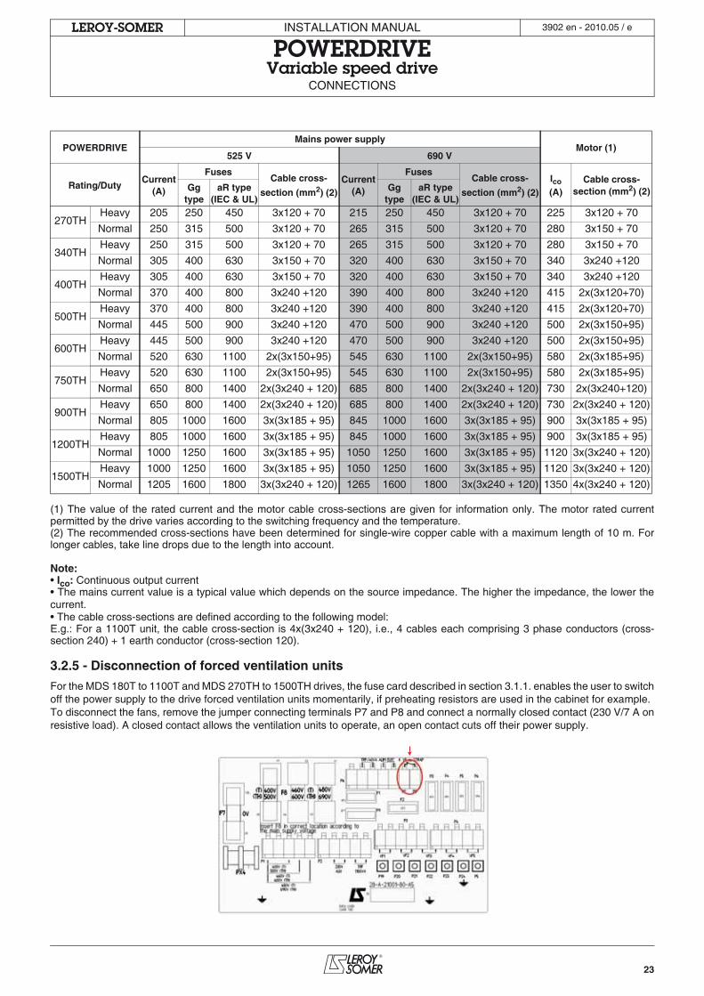
3.2.5 - Disconnection of forced ventilation units
For the MDS 180T to 1100T and MDS 270TH to 1500TH drives, the fuse card described in section 3.1.1. enables the user to switchoff the power supply to the drive forced ventilation units momentarily, if preheating resistors are used in the cabinet for example.To disconnect the fans, remove the jumper connecting terminals P7 and P8 and connect a normally closed contact (230 V/7 A onresistive load). A closed contact allows the ventilation units to operate, an open contact cuts off their power supply.
POWERDRIVEMains power supply
Motor (1)525 V 690 V
Rating/DutyCurrent
(A)
FusesCable cross-
section (mm2) (2)Current
(A)
FusesCable cross-
section (mm2) (2)Ico
(A)Cable cross-
section (mm2) (2)Gg type
aR type (IEC & UL)
Gg type
aR type (IEC & UL)
270THHeavy 205 250 450 3x120 + 70 215 250 450 3x120 + 70 225 3x120 + 70
Normal 250 315 500 3x120 + 70 265 315 500 3x120 + 70 280 3x150 + 70
340THHeavy 250 315 500 3x120 + 70 265 315 500 3x120 + 70 280 3x150 + 70
Normal 305 400 630 3x150 + 70 320 400 630 3x150 + 70 340 3x240 +120
400THHeavy 305 400 630 3x150 + 70 320 400 630 3x150 + 70 340 3x240 +120
Normal 370 400 800 3x240 +120 390 400 800 3x240 +120 415 2x(3x120+70)
500THHeavy 370 400 800 3x240 +120 390 400 800 3x240 +120 415 2x(3x120+70)
Normal 445 500 900 3x240 +120 470 500 900 3x240 +120 500 2x(3x150+95)
600THHeavy 445 500 900 3x240 +120 470 500 900 3x240 +120 500 2x(3x150+95)
Normal 520 630 1100 2x(3x150+95) 545 630 1100 2x(3x150+95) 580 2x(3x185+95)
750THHeavy 520 630 1100 2x(3x150+95) 545 630 1100 2x(3x150+95) 580 2x(3x185+95)
Normal 650 800 1400 2x(3x240 + 120) 685 800 1400 2x(3x240 + 120) 730 2x(3x240+120)
900THHeavy 650 800 1400 2x(3x240 + 120) 685 800 1400 2x(3x240 + 120) 730 2x(3x240 + 120)
Normal 805 1000 1600 3x(3x185 + 95) 845 1000 1600 3x(3x185 + 95) 900 3x(3x185 + 95)
1200THHeavy 805 1000 1600 3x(3x185 + 95) 845 1000 1600 3x(3x185 + 95) 900 3x(3x185 + 95)
Normal 1000 1250 1600 3x(3x185 + 95) 1050 1250 1600 3x(3x185 + 95) 1120 3x(3x240 + 120)
1500THHeavy 1000 1250 1600 3x(3x185 + 95) 1050 1250 1600 3x(3x185 + 95) 1120 3x(3x240 + 120)
Normal 1205 1600 1800 3x(3x240 + 120) 1265 1600 1800 3x(3x240 + 120) 1350 4x(3x240 + 120)
24
INSTALLATION MANUAL
POWERDRIVEVariable speed drive
CONNECTIONS
LEROY-SOMER 3902 en - 2010.05 / e
3.3 - Connection of the control• The POWERDRIVE inputs have a positive logicconfiguration. Using a drive with a control system
which has a different control logic may cause unwantedstarting of the motor.
• The control circuits in the drive are isolated fromthe power circuits by single insulation (IEC 664-1). Theinstaller must ensure that the external control circuits areisolated against any human contact.
• If the control circuits need to be connected tocircuits conforming to SELV safety requirements,additional insulation must be inserted to maintain theSELV classification.
3.3.1 - Characteristics of the control terminal blocks
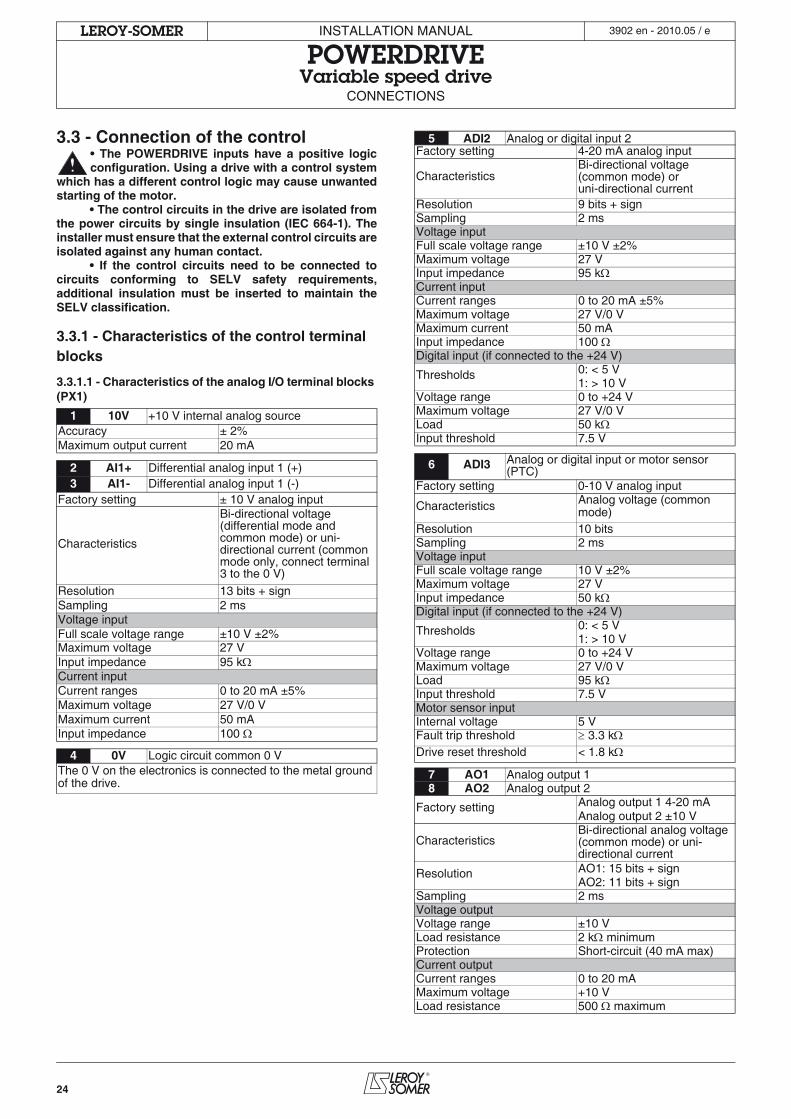
3.3.1.1 - Characteristics of the analog I/O terminal blocks (PX1)
1 10V +10 V internal analog sourceAccuracy ± 2%Maximum output current 20 mA
2 AI1+ Differential analog input 1 (+)3 AI1- Differential analog input 1 (-)
Factory setting ± 10 V analog input
Characteristics
Bi-directional voltage (differential mode and common mode) or uni-directional current (common mode only, connect terminal 3 to the 0 V)
Resolution 13 bits + signSampling 2 msVoltage inputFull scale voltage range ±10 V ±2%Maximum voltage 27 VInput impedance 95 kCurrent inputCurrent ranges 0 to 20 mA ±5%Maximum voltage 27 V/0 VMaximum current 50 mAInput impedance 100
4 0V Logic circuit common 0 VThe 0 V on the electronics is connected to the metal ground of the drive.
5 ADI2 Analog or digital input 2Factory setting 4-20 mA analog input
CharacteristicsBi-directional voltage (common mode) oruni-directional current
Resolution 9 bits + signSampling 2 msVoltage inputFull scale voltage range ±10 V ±2%Maximum voltage 27 VInput impedance 95 kCurrent inputCurrent ranges 0 to 20 mA ±5%Maximum voltage 27 V/0 VMaximum current 50 mAInput impedance 100 Digital input (if connected to the +24 V)
Thresholds 0: < 5 V1: > 10 V
Voltage range 0 to +24 VMaximum voltage 27 V/0 VLoad 50 kInput threshold 7.5 V
6 ADI3 Analog or digital input or motor sensor (PTC)
Factory setting 0-10 V analog input
Characteristics Analog voltage (common mode)
Resolution 10 bitsSampling 2 msVoltage inputFull scale voltage range 10 V ±2%Maximum voltage 27 VInput impedance 50 kDigital input (if connected to the +24 V)
Thresholds 0: < 5 V1: > 10 V
Voltage range 0 to +24 VMaximum voltage 27 V/0 VLoad 95 kInput threshold 7.5 VMotor sensor inputInternal voltage 5 VFault trip threshold 3.3 kDrive reset threshold < 1.8 k
7 AO1 Analog output 18 AO2 Analog output 2
Factory setting Analog output 1 4-20 mAAnalog output 2 ±10 V
CharacteristicsBi-directional analog voltage (common mode) or uni-directional current
Resolution AO1: 15 bits + signAO2: 11 bits + sign
Sampling 2 msVoltage outputVoltage range ±10 VLoad resistance 2 k minimumProtection Short-circuit (40 mA max)Current outputCurrent ranges 0 to 20 mAMaximum voltage +10 VLoad resistance 500 maximum
25
INSTALLATION MANUAL
POWERDRIVEVariable speed drive
CONNECTIONS
LEROY-SOMER 3902 en - 2010.05 / e
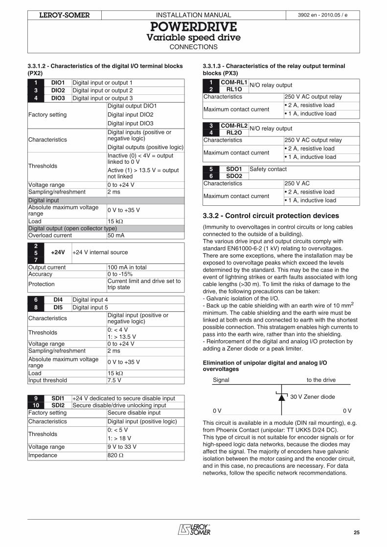
3.3.1.2 - Characteristics of the digital I/O terminal blocks (PX2)
3.3.1.3 - Characteristics of the relay output terminal blocks (PX3)
3.3.2 - Control circuit protection devices
(Immunity to overvoltages in control circuits or long cables connected to the outside of a building).The various drive input and output circuits comply with standard EN61000-6-2 (1 kV) relating to overvoltages.There are some exceptions, where the installation may be exposed to overvoltage peaks which exceed the levels determined by the standard. This may be the case in the event of lightning strikes or earth faults associated with long cable lengths (>30 m). To limit the risks of damage to the drive, the following precautions can be taken:- Galvanic isolation of the I/O.- Back up the cable shielding with an earth wire of 10 mm2 minimum. The cable shielding and the earth wire must be linked at both ends and connected to earth with the shortest possible connection. This stratagem enables high currents to pass into the earth wire, rather than into the shielding.- Reinforcement of the digital and analog I/O protection by adding a Zener diode or a peak limiter.
Elimination of unipolar digital and analog I/O overvoltages
This circuit is available in a module (DIN rail mounting), e.g. from Phoenix Contact (unipolar: TT UKK5 D/24 DC).This type of circuit is not suitable for encoder signals or for high-speed logic data networks, because the diodes may affect the signal. The majority of encoders have galvanic isolation between the motor casing and the encoder circuit, and in this case, no precautions are necessary. For data networks, follow the specific network recommendations.
1 DIO1 Digital input or output 13 DIO2 Digital input or output 24 DIO3 Digital input or output 3
Factory setting
Digital output DIO1
Digital input DIO2
Digital input DIO3
CharacteristicsDigital inputs (positive or negative logic)
Digital outputs (positive logic)
Thresholds
Inactive (0) < 4V = output linked to 0 VActive (1) > 13.5 V = output not linked
Voltage range 0 to +24 VSampling/refreshment 2 ms
Digital inputAbsolute maximum voltage range
0 V to +35 V
Load 15 kDigital output (open collector type)Overload current 50 mA
2+24V +24 V internal source5
7Output current 100 mA in totalAccuracy 0 to -15%
Protection Current limit and drive set to trip state
6 DI4 Digital input 48 DI5 Digital input 5
Characteristics Digital input (positive or negative logic)
Thresholds 0: < 4 V1: > 13.5 V
Voltage range 0 to +24 VSampling/refreshment 2 ms
Absolute maximum voltage range
0 V to +35 V
Load 15 kInput threshold 7.5 V
9 SDI1 +24 V dedicated to secure disable input10 SDI2 Secure disable/drive unlocking input
Factory setting Secure disable input
Characteristics Digital input (positive logic)
Thresholds0: < 5 V1: > 18 V
Voltage range 9 V to 33 V
Impedance 820
1 COM-RL1 N/O relay output2 RL1O
Characteristics 250 V AC output relay
Maximum contact current• 2 A, resistive load
• 1 A, inductive load
3 COM-RL2 N/O relay output4 RL2O
Characteristics 250 V AC output relay
Maximum contact current• 2 A, resistive load• 1 A, inductive load
5 SDO1 Safety contact6 SDO2
Characteristics 250 V AC
Maximum contact current• 2 A, resistive load• 1 A, inductive load
30 V Zener diode
Signal
0 V 0 V
to the drive
26
INSTALLATION MANUAL
POWERDRIVEVariable speed drive
CONNECTIONS
LEROY-SOMER 3902 en - 2010.05 / e
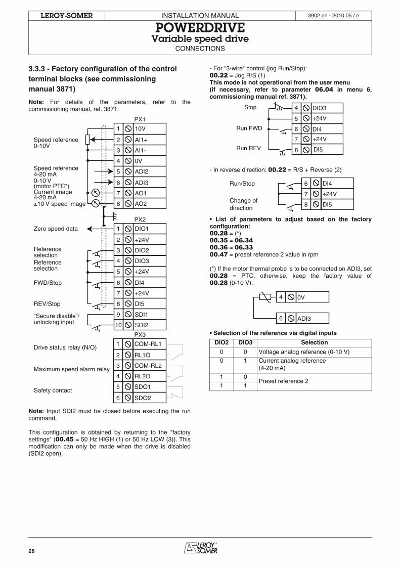
3.3.3 - Factory configuration of the control terminal blocks (see commissioning manual 3871)
Note: For details of the parameters, refer to thecommissioning manual, ref. 3871.
Note: Input SDI2 must be closed before executing the runcommand.
This configuration is obtained by returning to the "factorysettings" (00.45 = 50 Hz HIGH (1) or 50 Hz LOW (3)). Thismodification can only be made when the drive is disabled(SDI2 open).
- For "3-wire" control (jog Run/Stop):00.22 = Jog R/S (1)This mode is not operational from the user menu (if necessary, refer to parameter 06.04 in menu 6,commissioning manual ref. 3871).
- In reverse direction: 00.22 = R/S + Reverse (2)
• List of parameters to adjust based on the factoryconfiguration:00.28 = (*)00.35 = 06.3400.36 = 06.3300.47 = preset reference 2 value in rpm
(*) If the motor thermal probe is to be connected on ADI3, set00.28 = PTC, otherwise, keep the factory value of00.28 (0-10 V).
• Selection of the reference via digital inputs
10V
AI1+
AI1-
0V
ADI2
ADI3
COM-RL1
RL1O
COM-RL2
RL2O
SDO1
SDO2
AO2
AO1
DIO1
+24V
DIO2
DIO3
+24V
DI4
DI5
+24V
SDI2
SDI1
1
2
3
4
5
6
1
2
3
4
5
6
8
7
1
2
3
4
5
6
8
7
10
9
Speed reference0-10V
Speed reference4-20 mA0-10 V(motor PTC*)
Drive status relay (N/O)
Maximum speed alarm relay
Safety contact
±10 V speed image
Current image4-20 mA
Zero speed data
ReferenceselectionReferenceselection
FWD/Stop
REV/Stop
“Secure disable”/unlocking input
PX1
PX2
PX3DIO2 DIO3 Selection
0 0 Voltage analog reference (0-10 V)
0 1 Current analog reference(4-20 mA)
1 0Preset reference 2
1 1
DIO3
+24V
+24V
DI4
DI5Run REV
Run FWD
Stop 4
5
6
7
8
DI4
DI5
+24V
Run/Stop
Change ofdirection
6
8
7
0V
ADI3
4
6
27
INSTALLATION MANUAL
POWERDRIVEVariable speed drive
CONNECTIONS
LEROY-SOMER 3902 en - 2010.05 / e
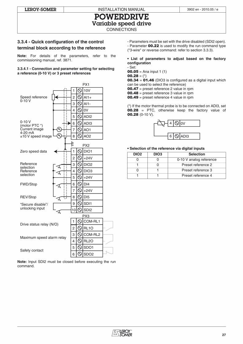
3.3.4 - Quick configuration of the control terminal block according to the reference
Note: For details of the parameters, refer to thecommissioning manual, ref. 3871.
3.3.4.1 - Connection and parameter setting for selecting a reference (0-10 V) or 3 preset references
Note: Input SDI2 must be closed before executing the runcommand.
- Parameters must be set with the drive disabled (SDI2 open).- Parameter 00.22 is used to modify the run command type("3-wire" or reverse command: refer to section 3.3.3).
• List of parameters to adjust based on the factoryconfiguration- Set: 00.05 = Ana input 1 (1)00.28 = (*)00.34 = 01.46 (DIO3 is configured as a digital input whichcan be used to select the reference)00.47 = preset reference 2 value in rpm00.48 = preset reference 3 value in rpm00.49 = preset reference 4 value in rpm
(*) If the motor thermal probe is to be connected on ADI3, set00.28 = PTC, otherwise keep the factory value of00.28 (0-10 V).
• Selection of the reference via digital inputs
10V
AI1+
AI1-
0V
ADI2
ADI3
COM-RL1
RL1O
COM-RL2
RL2O
SDO1
SDO2
AO2
AO1
DIO1
+24V
DIO2
DIO3
+24V
DI4
DI5
+24V
SDI2
SDI1
Speed reference0-10 V
0-10 V (motor PTC *)
Drive status relay (N/O)
Maximum speed alarm relay
Safety contact
±10 V speed image
Current image4-20 mA
Zero speed data
ReferenceselectionReferenceselection
FWD/Stop
REV/Stop
“Secure disable”/unlocking input
1
2
3
4
5
6
1
2
3
4
5
6
8
7
1
2
3
4
5
6
8
7
10
9
PX1
PX2
PX3
DIO2 DIO3 Selection0 0 0-10 V analog reference1 0 Preset reference 2
0 1 Preset reference 3
1 1 Preset reference 4
0V
ADI3
4
6
28
INSTALLATION MANUAL
POWERDRIVEVariable speed drive
CONNECTIONS
LEROY-SOMER 3902 en - 2010.05 / e
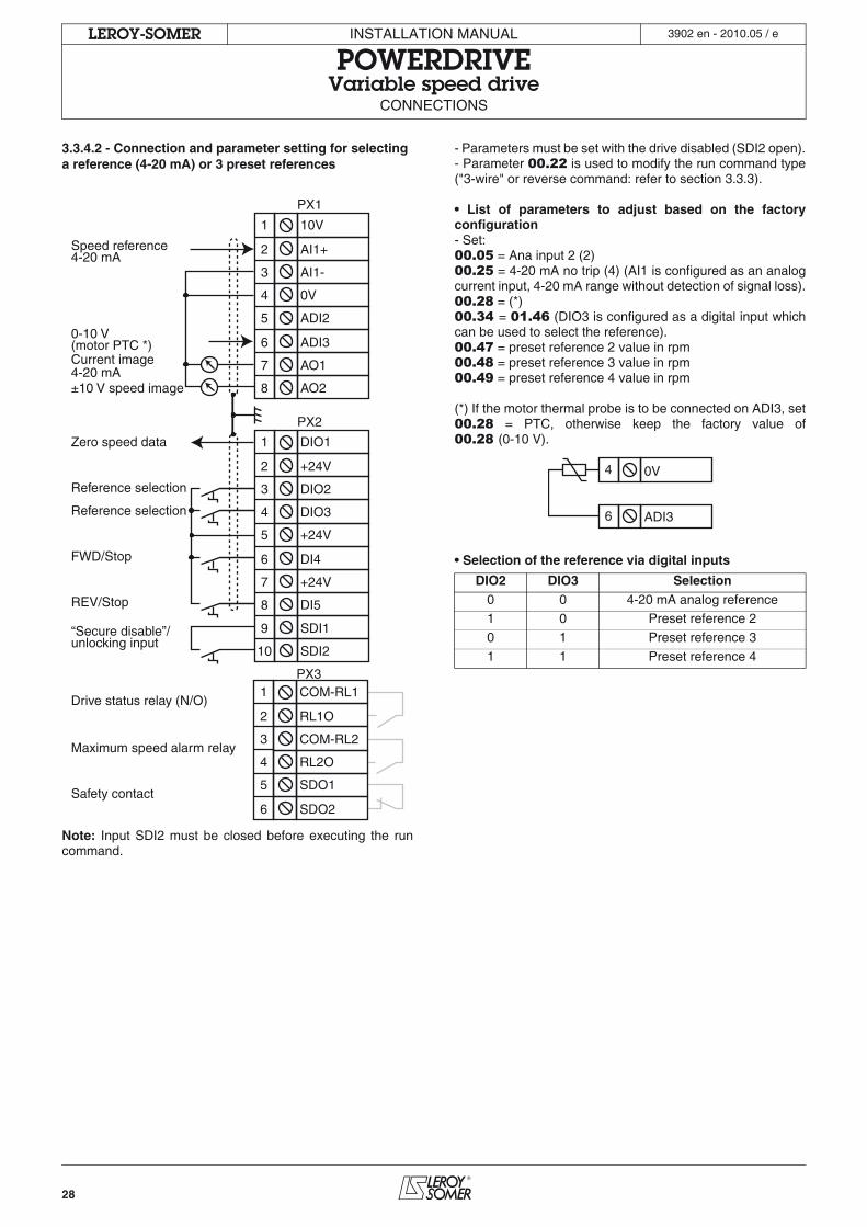
3.3.4.2 - Connection and parameter setting for selecting a reference (4-20 mA) or 3 preset references
Note: Input SDI2 must be closed before executing the runcommand.
- Parameters must be set with the drive disabled (SDI2 open).- Parameter 00.22 is used to modify the run command type("3-wire" or reverse command: refer to section 3.3.3).
• List of parameters to adjust based on the factoryconfiguration- Set:00.05 = Ana input 2 (2)00.25 = 4-20 mA no trip (4) (AI1 is configured as an analogcurrent input, 4-20 mA range without detection of signal loss).00.28 = (*)00.34 = 01.46 (DIO3 is configured as a digital input whichcan be used to select the reference).00.47 = preset reference 2 value in rpm00.48 = preset reference 3 value in rpm00.49 = preset reference 4 value in rpm
(*) If the motor thermal probe is to be connected on ADI3, set00.28 = PTC, otherwise keep the factory value of00.28 (0-10 V).
• Selection of the reference via digital inputs
10V
AI1+
AI1-
0V
ADI2
ADI3
AO2
AO1
DIO1
+24V
DIO2
DIO3
+24V
DI4
DI5
+24V
SDI2
SDI1
Speed reference4-20 mA
0-10 V(motor PTC *)
Drive status relay (N/O)
Maximum speed alarm relay
Safety contact
±10 V speed image
Current image4-20 mA
Zero speed data
Reference selection
Reference selection
FWD/Stop
REV/Stop
“Secure disable”/unlocking input
1
2
3
4
5
6
1
2
3
4
5
6
8
7
1
2
3
4
5
6
8
7
10
9
PX1
PX2
PX3COM-RL1
RL1O
COM-RL2
RL2O
SDO1
SDO2
DIO2 DIO3 Selection0 0 4-20 mA analog reference1 0 Preset reference 2
0 1 Preset reference 3
1 1 Preset reference 4
0V
ADI3
4
6
29
INSTALLATION MANUAL
POWERDRIVEVariable speed drive
CONNECTIONS
LEROY-SOMER 3902 en - 2010.05 / e
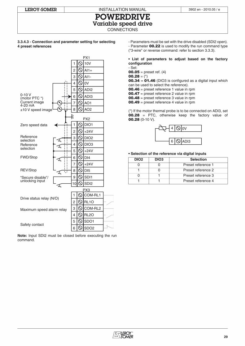
3.3.4.3 - Connection and parameter setting for selecting 4 preset references
Note: Input SDI2 must be closed before executing the runcommand.
- Parameters must be set with the drive disabled (SDI2 open).- Parameter 00.22 is used to modify the run command type("3-wire" or reverse command: refer to section 3.3.3).
• List of parameters to adjust based on the factoryconfiguration- Set:00.05 = preset ref. (4)00.28 = (*)00.34 = 01.46 (DIO3 is configured as a digital input whichcan be used to select the reference).00.46 = preset reference 1 value in rpm00.47 = preset reference 2 value in rpm00.48 = preset reference 3 value in rpm00.49 = preset reference 4 value in rpm
(*) If the motor thermal probe is to be connected on ADI3, set00.28 = PTC, otherwise keep the factory value of00.28 (0-10 V).
• Selection of the reference via digital inputs
10V
AI1+
AI1-
0V
ADI2
ADI3
AO2
AO1
DIO1
+24V
DIO2
DIO3
+24V
DI4
DI5
+24V
SDI2
SDI1
0-10 V(motor PTC *)
Drive status relay (N/O)
Maximum speed alarm relay
Safety contact
±10 V speed image
Current image4-20 mA
Zero speed data
ReferenceselectionReferenceselection
FWD/Stop
REV/Stop
“Secure disable”/unlocking input
1
2
3
4
5
6
1
2
3
4
5
6
8
7
1
2
3
4
5
6
8
7
10
9
PX1
PX2
PX3COM-RL1
RL1O
COM-RL2
RL2O
SDO1
SDO2
DIO2 DIO3 Selection0 0 Preset reference 11 0 Preset reference 2
0 1 Preset reference 3
1 1 Preset reference 4
0V
ADI3
4
6
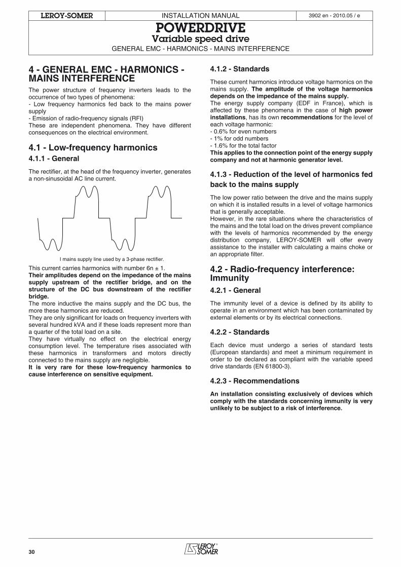
30
INSTALLATION MANUAL
POWERDRIVEVariable speed drive
GENERAL EMC - HARMONICS - MAINS INTERFERENCE
LEROY-SOMER 3902 en - 2010.05 / e
4 - GENERAL EMC - HARMONICS - MAINS INTERFERENCEThe power structure of frequency inverters leads to theoccurrence of two types of phenomena:- Low frequency harmonics fed back to the mains powersupply- Emission of radio-frequency signals (RFI)These are independent phenomena. They have differentconsequences on the electrical environment.
4.1 - Low-frequency harmonics4.1.1 - General
The rectifier, at the head of the frequency inverter, generatesa non-sinusoidal AC line current.
This current carries harmonics with number 6n ± 1.Their amplitudes depend on the impedance of the mainssupply upstream of the rectifier bridge, and on thestructure of the DC bus downstream of the rectifierbridge.The more inductive the mains supply and the DC bus, themore these harmonics are reduced.They are only significant for loads on frequency inverters withseveral hundred kVA and if these loads represent more thana quarter of the total load on a site.They have virtually no effect on the electrical energyconsumption level. The temperature rises associated withthese harmonics in transformers and motors directlyconnected to the mains supply are negligible.It is very rare for these low-frequency harmonics tocause interference on sensitive equipment.
4.1.2 - Standards
These current harmonics introduce voltage harmonics on themains supply. The amplitude of the voltage harmonicsdepends on the impedance of the mains supply.The energy supply company (EDF in France), which isaffected by these phenomena in the case of high powerinstallations, has its own recommendations for the level ofeach voltage harmonic:- 0.6% for even numbers- 1% for odd numbers- 1.6% for the total factorThis applies to the connection point of the energy supplycompany and not at harmonic generator level.
4.1.3 - Reduction of the level of harmonics fedback to the mains supply
The low power ratio between the drive and the mains supplyon which it is installed results in a level of voltage harmonicsthat is generally acceptable.However, in the rare situations where the characteristics ofthe mains and the total load on the drives prevent compliancewith the levels of harmonics recommended by the energydistribution company, LEROY-SOMER will offer everyassistance to the installer with calculating a mains choke oran appropriate filter.
4.2 - Radio-frequency interference: Immunity4.2.1 - General
The immunity level of a device is defined by its ability tooperate in an environment which has been contaminated byexternal elements or by its electrical connections.
4.2.2 - Standards
Each device must undergo a series of standard tests(European standards) and meet a minimum requirement inorder to be declared as compliant with the variable speeddrive standards (EN 61800-3).
4.2.3 - Recommendations
An installation consisting exclusively of devices whichcomply with the standards concerning immunity is veryunlikely to be subject to a risk of interference.
I mains supply line used by a 3-phase rectifier.
31
INSTALLATION MANUAL
POWERDRIVEVariable speed drive
GENERAL EMC - HARMONICS - MAINS INTERFERENCE
LEROY-SOMER 3902 en - 2010.05 / e
4.3 - Radio-frequency interference: Emission4.3.1 - GeneralFrequency inverters use high-speed switches (transistors,semi-conductors) which switch high voltages and currents athigh frequencies (several kHz). This provides better efficiencyand a low level of motor noise.As a result, they generate radio-frequency signals which maydisturb operation of other equipment or distort measurementstaken by sensors:- Due to high-frequency leakage currents which escape toearth via the stray capacity of the drive/motor cable and thatof the motor via the metal structures which support the motor.- By conduction or feedback of R.F. signals on the powersupply cable: conducted emissions- By direct radiation near to the mains supply power cable orthe drive/motor cable: radiated emissionsThese phenomena are of direct interest to the user.The frequency range concerned (radio frequency) does notaffect the energy supply company.
4.3.2 - StandardsThe maximum emission level is set by the standards forvariable speed drives (EN 61800-3).
4.3.3 - Recommendations• Experience has shown that the levels set by the standardsdo not necessarily need to be observed to eliminateinterference phenomena.• Following the basic precautions in section 4.5 generallyresults in the correct operation of the installation.
4.4 - Influence of the mains power supplyThe mains power supply may be subject to interference(voltage drops, voltage imbalances, fluctuation, overvoltages,etc.) which can have an actual negative impact on theperformance and reliability of all electronic power equipment,including drives.LEROY-SOMER drives are designed to operate with a mainspower supply typical of industrial sites throughout the world.However, for each installation, it is important to know thecharacteristics of the mains power supply in order to carry outcorrective measures in the event of abnormal conditions.
4.4.1 - Transient overvoltagesThere are numerous reasons for overvoltages on an electricalinstallation:- Connection/disconnection of a bank of capacitors whichincreases the cos .- Short-circuit in a high-power device when an isolator isopened and/or fuses are damaged.- Devices (ovens, DC or AC drives, etc.) with high-powerthyristors (>1 MW).- High-power motors during start-up.- Overhead power supply.- Etc.The POWERDRIVE incorporates high-power overvoltagelimiters, which protect the drive and enable reliable operationon industrial sites.If transient overvoltages are a regular occurrence, werecommend the use of a mains choke.
4.4.2 - Unbalanced power supplyAs is seen on an electric motor, the line current imbalance ofa drive operating on an unbalanced mains supply may beseveral times the value of the voltage imbalance measuredon the power supply.A highly unbalanced mains supply (> 2%) associated with alow mains impedance may result in a high level of stress onthe components at the input stage of a drive.
Mains chokes can be installed upstream of a POWERDRIVEsupplied by an unbalanced mains supply in order to reducethe current imbalance factor (the chokes are mounted inseries for the 1100T rating and all TH ratings).
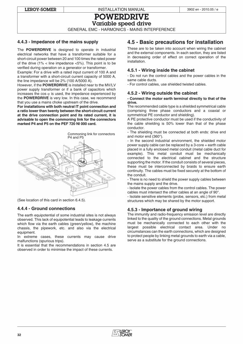
32
INSTALLATION MANUAL
POWERDRIVEVariable speed drive
GENERAL EMC - HARMONICS - MAINS INTERFERENCE
LEROY-SOMER 3902 en - 2010.05 / e
4.4.3 - Impedance of the mains supply
The POWERDRIVE is designed to operate in industrialelectrical networks that have a transformer suitable for ashort-circuit power between 20 and 100 times the rated powerof the drive (1% < line impedance <5%). This point is to beverified during operation on a generator or transformer.Example: For a drive with a rated input current of 100 A anda transformer with a short-circuit current capacity of 5000 A,the line impedance will be 2% (100 A/5000 A).However, if the POWERDRIVE is installed near to the MV/LVpower supply transformer or if a bank of capacitors whichincreases the cos is used, the impedance experienced bythe POWERDRIVE is very low. In this case, we recommendthat you use a mains choke upstream of the drive.For installations with both neutral IT point connection anda ratio lower than twenty between the short-circuit currentat the drive connection point and its rated current, it isadvisable to open the commoning link for the connectorsmarked P4 and P5 on the PEF 720 NI 000 card.
(See location of this card in section 6.4.5).
4.4.4 - Ground connectionsThe earth equipotential of some industrial sites is not alwaysobserved. This lack of equipotential leads to leakage currentswhich flow via the earth cables (green/yellow), the machinechassis, the pipework, etc. and also via the electricalequipment.In extreme cases, these currents may cause drivemalfunctions (spurious trips). It is essential that the recommendations in section 4.5 areobserved in order to minimise the impact of these currents.
4.5 - Basic precautions for installation These are to be taken into account when wiring the cabinetand the external components. In each section, they are listedin decreasing order of effect on correct operation of theinstallation.
4.5.1 - Wiring inside the cabinet- Do not run the control cables and the power cables in thesame cable ducts.- For control cables, use shielded twisted cables.
4.5.2 - Wiring outside the cabinet- Connect the motor earth terminal directly to that of thedrive.The recommended cable type is a shielded symmetrical cable(comprising three phase conductors and a coaxial orsymmetrical PE conductor and shielding).A PE protective conductor must be used if the conductivity ofthe cable shielding is 50% lower than that of the phaseconductor.- The shielding must be connected at both ends: drive endand motor end (360°).- In the second industrial environment, the shielded motorpower supply cable can be replaced by a 3-core + earth cableplaced in a fully enclosed metal conduit (metal cable duct forexample). This metal conduit must be mechanicallyconnected to the electrical cabinet and the structuresupporting the motor. If the conduit consists of several pieces,these must be interconnected by braids to ensure earthcontinuity. The cables must be fixed securely at the bottom ofthe conduit.- There is no need to shield the power supply cables betweenthe mains supply and the drive.- Isolate the power cables from the control cables. The powercables must intersect the other cables at an angle of 90°.- Isolate sensitive elements (probe, sensors, etc.) from metalstructures which may be shared by the motor support.
4.5.3 - Importance of ground wiringThe immunity and radio-frequency emission level are directlylinked to the quality of the ground connections. Metal groundsmust be mechanically connected to each other with thelargest possible electrical contact area. Under nocircumstances can the earth connections, which are designedto protect people by linking metal grounds to earth via a cable,serve as a substitute for the ground connections.
Commoning link for connectorsP4 and P5
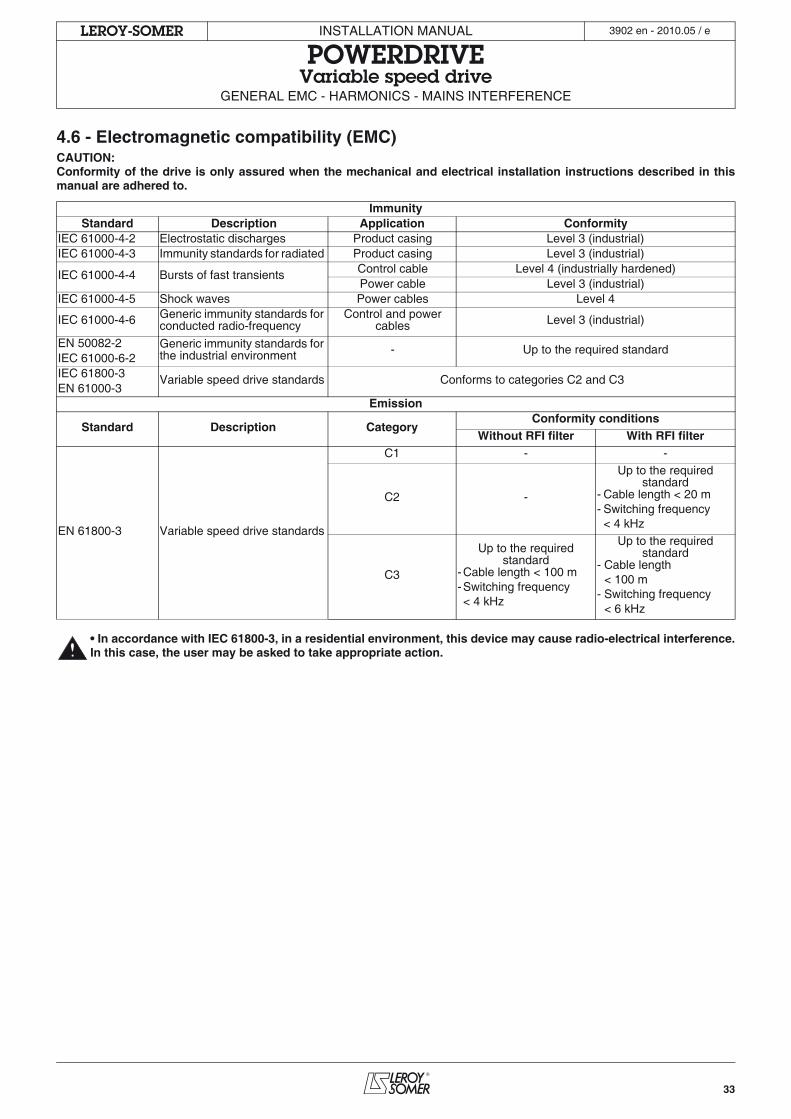
33
INSTALLATION MANUAL
POWERDRIVEVariable speed drive
GENERAL EMC - HARMONICS - MAINS INTERFERENCE
LEROY-SOMER 3902 en - 2010.05 / e
4.6 - Electromagnetic compatibility (EMC)CAUTION:Conformity of the drive is only assured when the mechanical and electrical installation instructions described in thismanual are adhered to.
• In accordance with IEC 61800-3, in a residential environment, this device may cause radio-electrical interference.In this case, the user may be asked to take appropriate action.
ImmunityStandard Description Application Conformity
IEC 61000-4-2 Electrostatic discharges Product casing Level 3 (industrial)IEC 61000-4-3 Immunity standards for radiated Product casing Level 3 (industrial)
IEC 61000-4-4 Bursts of fast transients Control cable Level 4 (industrially hardened)Power cable Level 3 (industrial)
IEC 61000-4-5 Shock waves Power cables Level 4
IEC 61000-4-6 Generic immunity standards for conducted radio-frequency
Control and power cables Level 3 (industrial)
EN 50082-2 Generic immunity standards for the industrial environment - Up to the required standard
IEC 61000-6-2IEC 61800-3 Variable speed drive standards Conforms to categories C2 and C3EN 61000-3
Emission
Standard Description CategoryConformity conditions
Without RFI filter With RFI filter
EN 61800-3 Variable speed drive standards
C1 - -
C2 -
Up to the required standard
- Cable length < 20 m- Switching frequency< 4 kHz
C3
Up to the required standard
-Cable length < 100 m-Switching frequency< 4 kHz
Up to the required standard
- Cable length< 100 m
- Switching frequency< 6 kHz
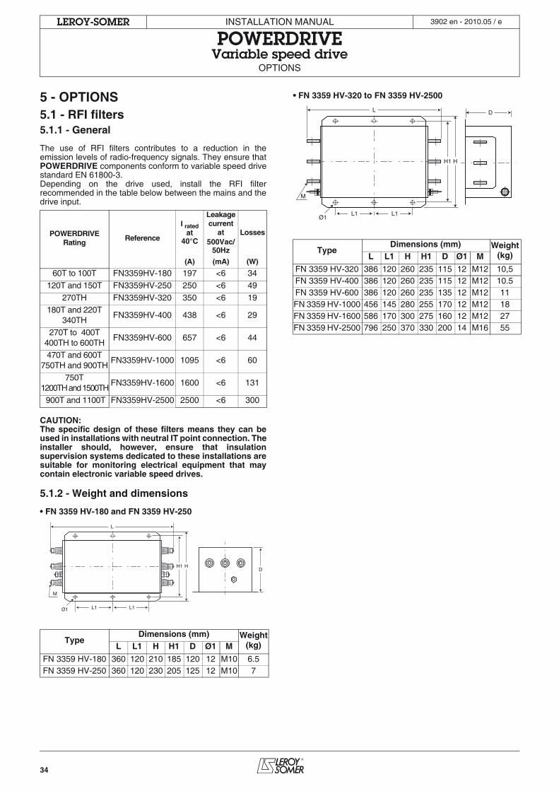
34
INSTALLATION MANUAL
POWERDRIVEVariable speed drive
OPTIONS
LEROY-SOMER 3902 en - 2010.05 / e
5 - OPTIONS5.1 - RFI filters5.1.1 - General
The use of RFI filters contributes to a reduction in theemission levels of radio-frequency signals. They ensure thatPOWERDRIVE components conform to variable speed drivestandard EN 61800-3.Depending on the drive used, install the RFI filterrecommended in the table below between the mains and thedrive input.
CAUTION:The specific design of these filters means they can beused in installations with neutral IT point connection. Theinstaller should, however, ensure that insulationsupervision systems dedicated to these installations aresuitable for monitoring electrical equipment that maycontain electronic variable speed drives.
5.1.2 - Weight and dimensions
• FN 3359 HV-180 and FN 3359 HV-250
• FN 3359 HV-320 to FN 3359 HV-2500
POWERDRIVERating
Reference
I rated at
40°C
Leakage current
at500Vac/
50Hz
Losses
(A) (mA) (W)
60T to 100T FN3359HV-180 197 <6 34
120T and 150T FN3359HV-250 250 <6 49
270TH FN3359HV-320 350 <6 19180T and 220T
340THFN3359HV-400 438 <6 29
270T to 400T400TH to 600TH
FN3359HV-600 657 <6 44
470T and 600T750TH and 900TH
FN3359HV-1000 1095 <6 60
750T1200TH and 1500TH
FN3359HV-1600 1600 <6 131
900T and 1100T FN3359HV-2500 2500 <6 300
TypeDimensions (mm) Weight
(kg)L L1 H H1 D Ø1 M
FN 3359 HV-180 360 120 210 185 120 12 M10 6.5FN 3359 HV-250 360 120 230 205 125 12 M10 7
L
L1 L1
HH1
Ø1
M
D
TypeDimensions (mm) Weight
(kg)L L1 H H1 D Ø1 M
FN 3359 HV-320 386 120 260 235 115 12 M12 10,5FN 3359 HV-400 386 120 260 235 115 12 M12 10.5FN 3359 HV-600 386 120 260 235 135 12 M12 11FN 3359 HV-1000 456 145 280 255 170 12 M12 18FN 3359 HV-1600 586 170 300 275 160 12 M12 27FN 3359 HV-2500 796 250 370 330 200 14 M16 55
L D
L1 L1
HH1
Ø1
M
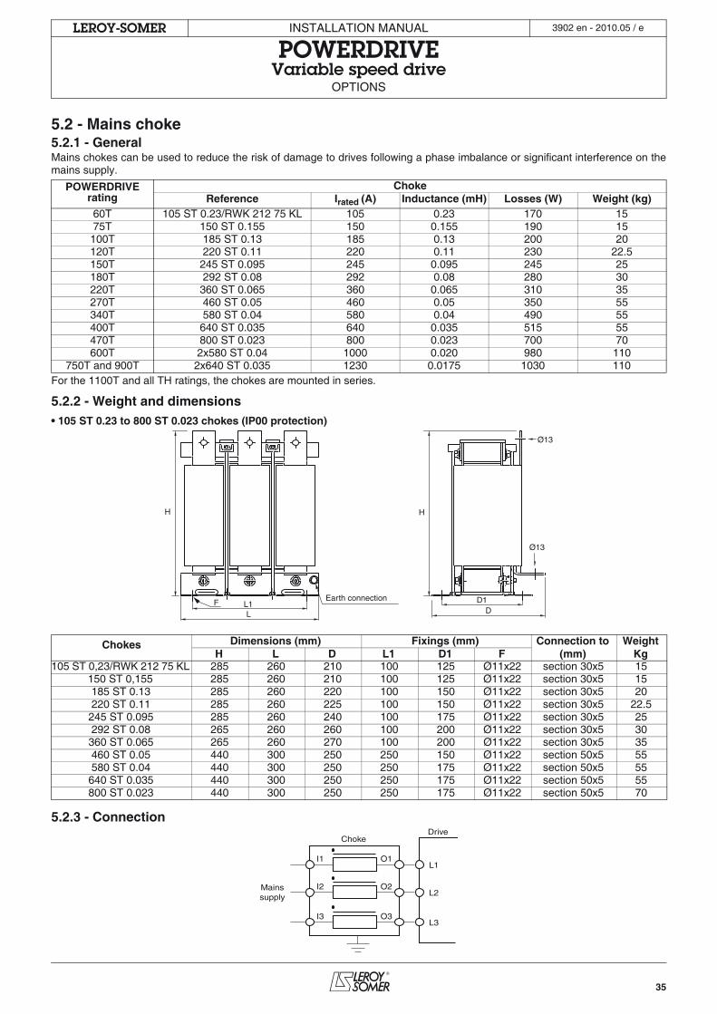
35
INSTALLATION MANUAL
POWERDRIVEVariable speed drive
OPTIONS
LEROY-SOMER 3902 en - 2010.05 / e
5.2 - Mains choke5.2.1 - GeneralMains chokes can be used to reduce the risk of damage to drives following a phase imbalance or significant interference on themains supply.
For the 1100T and all TH ratings, the chokes are mounted in series.
5.2.2 - Weight and dimensions• 105 ST 0.23 to 800 ST 0.023 chokes (IP00 protection)
5.2.3 - Connection
POWERDRIVE rating
ChokeReference Irated (A) Inductance (mH) Losses (W) Weight (kg)
60T 105 ST 0.23/RWK 212 75 KL 105 0.23 170 1575T 150 ST 0.155 150 0.155 190 15100T 185 ST 0.13 185 0.13 200 20120T 220 ST 0.11 220 0.11 230 22.5150T 245 ST 0.095 245 0.095 245 25180T 292 ST 0.08 292 0.08 280 30220T 360 ST 0.065 360 0.065 310 35270T 460 ST 0.05 460 0.05 350 55340T 580 ST 0.04 580 0.04 490 55400T 640 ST 0.035 640 0.035 515 55470T 800 ST 0.023 800 0.023 700 70600T 2x580 ST 0.04 1000 0.020 980 110
750T and 900T 2x640 ST 0.035 1230 0.0175 1030 110
Chokes Dimensions (mm) Fixings (mm) Connection to WeightH L D L1 D1 F (mm) Kg
105 ST 0,23/RWK 212 75 KL 285 260 210 100 125 Ø11x22 section 30x5 15150 ST 0,155 285 260 210 100 125 Ø11x22 section 30x5 15185 ST 0.13 285 260 220 100 150 Ø11x22 section 30x5 20220 ST 0.11 285 260 225 100 150 Ø11x22 section 30x5 22.5
245 ST 0.095 285 260 240 100 175 Ø11x22 section 30x5 25292 ST 0.08 265 260 260 100 200 Ø11x22 section 30x5 30
360 ST 0.065 265 260 270 100 200 Ø11x22 section 30x5 35460 ST 0.05 440 300 250 250 150 Ø11x22 section 50x5 55580 ST 0.04 440 300 250 250 175 Ø11x22 section 50x5 55
640 ST 0.035 440 300 250 250 175 Ø11x22 section 50x5 55800 ST 0.023 440 300 250 250 175 Ø11x22 section 50x5 70
H
DD1
H
LL1
Ø13
Ø13
FEarth connection
I1
Mainssupply
ChokeDrive
O1
I2 O2
I3 O3
L1
L2
L3
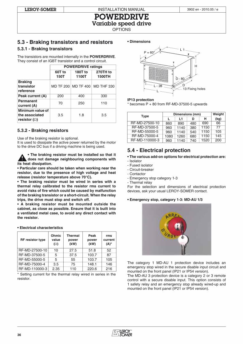
36
INSTALLATION MANUAL
POWERDRIVEVariable speed drive
OPTIONS
LEROY-SOMER 3902 en - 2010.05 / e
5.3 - Braking transistors and resistors5.3.1 - Braking transistors
The transistors are mounted internally in the POWERDRIVE.They consist of an IGBT transistor and a control circuit.
5.3.2 - Braking resistors
Use of the braking resistor is optional.It is used to dissipate the active power returned by the motorto the drive DC bus if a driving machine is being used.
• The braking resistor must be installed so that itdoes not damage neighbouring components with
its heat dissipation.• Particular care should be taken when working near theresistor, due to the presence of high voltage and heatrelease (resistor temperature above 70°C).• The braking resistor must be wired in series with athermal relay calibrated to the resistor rms current toavoid risks of fire which could be caused by malfunctionof the braking transistor or a short-circuit. When the relaytrips, the drive must stop and switch off.• A braking resistor must be mounted outside thecabinet, as close as possible. Ensure that it is built intoa ventilated metal case, to avoid any direct contact withthe resistor.
• Electrical characteristics
* Setting current for the thermal relay wired in series in theresistor.
• Dimensions
IP13 protection* becomes P + 80 from RF-MD-37500-5 upwards
5.4 - Electrical protection• The various add-on options for electrical protection are:- Isolator- Fused isolator- Circuit-breaker- Contactor- Emergency stop category 1-3- Thermal relayFor the selection and dimensions of electrical protectiondevices, ask your usual LEROY-SOMER contact.
• Emergency stop, category 1-3: MD-AU 1/3
The category 1 MD-AU 1 protection device includes anemergency stop wired in the secure disable input circuit andmounted on the front panel (IP21 or IP54 version).The MD-AU 3 protection device is a category 2 or 3 remotecontrol with a secure disable input. This option consists of1 safety relay and an emergency stop already wired-up andmounted on the front panel (IP21 or IP54 version).
POWERDRIVE ratings60T to 150T
180T to 1100T
270TH to 1500TH
Braking transistor reference
MD TF 200 MD TF 400 MD THF 330
Peak current (A) 200 400 330Permanent current (A)
70 250 110
Minimum value of the associated resistor ( )
3.5 1.8 3.5
RF resistor typeOhmic value
( )
Thermal power(kW)
Peakpower(kW)
rms current
(A)*
RF-MD-27500-10 10 27.5 51.8 52RF-MD-37500-5 5 37.5 103.7 87RF-MD-55000-5 5 55 103.7 105RF-MD-75000-4 3.5 75 148.1 146RF-MD-110000-3 2.35 110 220.6 216
Type Dimensions (mm) WeightL L1 D H (kg)
RF-MD-27500-10 860 890 480 690 66RF-MD-37500-5 960 1140 380 1150 77RF-MD-55000-5 960 1140 540 1150 105RF-MD-75000-4 1080 1260 680 1150 145
RF-MD-110000-3 960 1140 740 1520 200
L 1
H
D13 Fixing holes
D - 80
L - 28
L
P + 60*
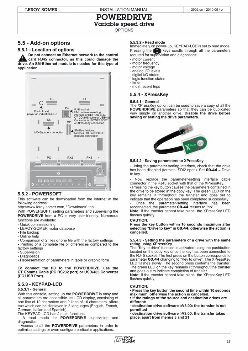
37
INSTALLATION MANUAL
POWERDRIVEVariable speed drive
OPTIONS
LEROY-SOMER 3902 en - 2010.05 / e
5.5 - Add-on options5.5.1 - Location of options
Do not connect an Ethernet network to the controlcard RJ45 connector, as this could damage the
drive. An SM-Ethernet module is needed for this type ofapplication.
5.5.2 - POWERSOFTThis software can be downloaded from the Internet at thefollowing address:http://www.leroy-somer.com, "Downloads" tabWith POWERSOFT, setting parameters and supervising thePOWERDRIVE from a PC is very user-friendly. Numerousfunctions are available:- Quick commissioning- LEROY-SOMER motor database- File backup- Online help- Comparison of 2 files or one file with the factory settings- Printing of a complete file or differences compared to thefactory settings- Supervision- Diagnostics- Representation of parameters in table or graphic form
To connect the PC to the POWERDRIVE, use theCT Comms Cable (PC RS232 port) or USB/485 Converter(PC USB Port).
5.5.3 - KEYPAD-LCD5.5.3.1 - GeneralWith this console, setting up the POWERDRIVE is easy andall parameters are accessible. Its LCD display, consisting ofone line of 12 characters and 2 lines of 16 characters, offerstext which can be displayed in 5 languages (English, French,German, Italian and Spanish).The KEYPAD-LCD has 2 main functions:- A read mode for POWERDRIVE supervision anddiagnostics.- Access to all the POWERDRIVE parameters in order tooptimise settings or even configure particular applications.
5.5.3.2 - Read modeImmediately on power-up, KEYPAD-LCD is set to read mode.Pressing the keys scrolls through all the parametersrequired for supervision and diagnostics:- motor current- motor frequency- motor voltage- analog I/O levels- digital I/O states- logic function states- timer- most recent trips
5.5.4 - XPressKey
5.5.4.1 - GeneralThe XPressKey option can be used to save a copy of all thePOWERDRIVE parameters so that they can be duplicatedvery simply on another drive. Disable the drive beforesaving or setting the drive parameters.
5.5.4.2 - Saving parameters to XPressKey- Using the parameter-setting interface, check that the drivehas been disabled (terminal SDI2 open). Set 00.44 = Driveto key.- Now replace the parameter-setting interface cableconnector in the RJ45 socket with that of the XPressKey.- Pressing the key button causes the parameters contained inthe drive to be stored in the copy key. The green LED on thekey remains lit throughout the transfer and goes out toindicate that the operation has been completed successfully. - Once the parameter-setting interface has beenreconnected, the parameter 00.44 returns to "no".Note: If the transfer cannot take place, the XPressKey LEDflashes quickly.CAUTION:Press the key button within 10 seconds maximum afterselecting "Drive to key" in 00.44, otherwise the action iscancelled.
5.5.4.3 - Setting the parameters of a drive with the samerating using XPressKeyThe "Key to drive" function is activated using the pushbuttonlocated on the copy key once the key has been connected tothe RJ45 socket. The first press on the button corresponds toparameter 00.44 changing to "Key to drive". The XPressKeyLED flashes slowly. The second press confirms the transfer.The green LED on the key remains lit throughout the transferand goes out to indicate completion of transfer.Note: If the transfer cannot take place, the XPressKey LEDflashes quickly.
CAUTION:• Press the key button the second time within 10 secondsmaximum, otherwise the action is cancelled.• If the ratings of the source and destination drives are different:- destination drive software <V3.00: the transfer is not permitted- destination drive software V3.00: the transfer takes place, apart from menus 5 and 21
RJ45 socket: HMI parameter-setting interface or KEYPAD-LCD, CT COMMS cable or USB/485 Converter for POWERSOFT, or XPressKey connection
X4
X2X6
PX1 PX2 PX3
X3
P4
SM-Bus fieldbus, Modbus RTU and PX-I/O modules connection
MD-Encoder connection
Control card power-on indication LED
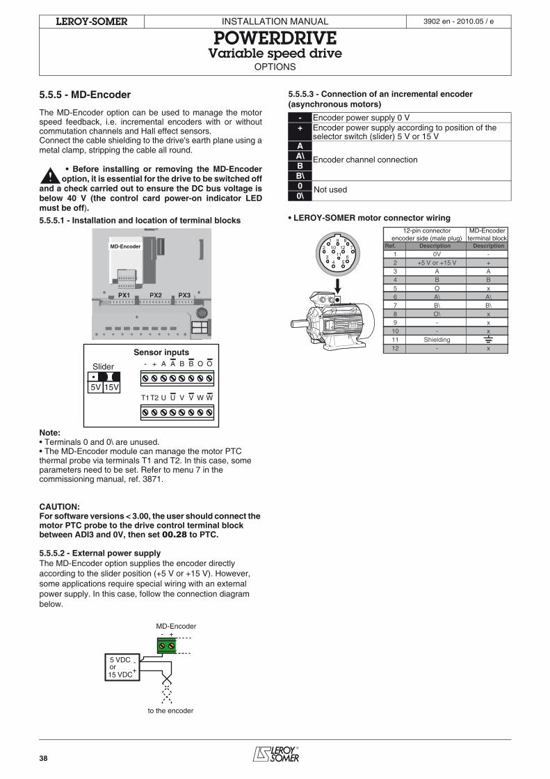
38
INSTALLATION MANUAL
POWERDRIVEVariable speed drive
OPTIONS
LEROY-SOMER 3902 en - 2010.05 / e
5.5.5 - MD-Encoder
The MD-Encoder option can be used to manage the motorspeed feedback, i.e. incremental encoders with or withoutcommutation channels and Hall effect sensors.Connect the cable shielding to the drive's earth plane using ametal clamp, stripping the cable all round.
• Before installing or removing the MD-Encoderoption, it is essential for the drive to be switched off
and a check carried out to ensure the DC bus voltage isbelow 40 V (the control card power-on indicator LEDmust be off).
5.5.5.1 - Installation and location of terminal blocks
Note: • Terminals 0 and 0\ are unused.• The MD-Encoder module can manage the motor PTC thermal probe via terminals T1 and T2. In this case, some parameters need to be set. Refer to menu 7 in the commissioning manual, ref. 3871.
CAUTION:For software versions < 3.00, the user should connect the motor PTC probe to the drive control terminal block between ADI3 and 0V, then set 00.28 to PTC.
5.5.5.2 - External power supplyThe MD-Encoder option supplies the encoder directly according to the slider position (+5 V or +15 V). However, some applications require special wiring with an external power supply. In this case, follow the connection diagram below.
5.5.5.3 - Connection of an incremental encoder (asynchronous motors)
• LEROY-SOMER motor connector wiring
Sensor inputs
Slider - + A B O
T1T2 U V W
A B O
U V W
MD-Encoder
5V 15V
- +
+-5 VDC
or15 VDC
MD-Encoder
to the encoder
- Encoder power supply 0 V+ Encoder power supply according to position of the
selector switch (slider) 5 V or 15 VA
Encoder channel connectionA\BB\0 Not used0\
12-pin connectorencoder side (male plug)
MD-Encoderterminal block1 9 8
2 10
34 5
611
12 7 Ref.
123456789101112
-+ABxA\B\xxx
x
0V+5 V or +15 V
ABOA\B\O\--
Shielding-
Description Description
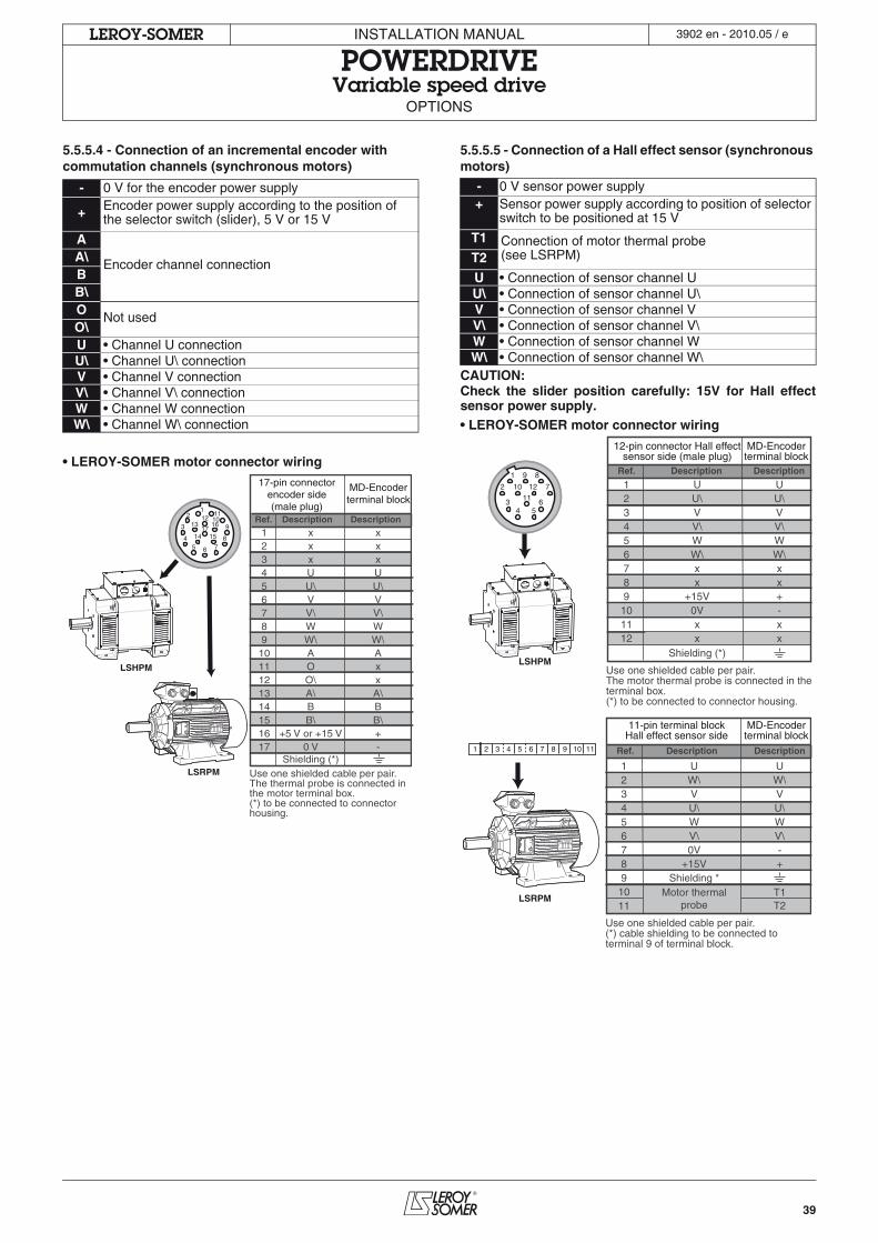
39
INSTALLATION MANUAL
POWERDRIVEVariable speed drive
OPTIONS
LEROY-SOMER 3902 en - 2010.05 / e
5.5.5.4 - Connection of an incremental encoder with commutation channels (synchronous motors)
• LEROY-SOMER motor connector wiring
5.5.5.5 - Connection of a Hall effect sensor (synchronous motors)
CAUTION:Check the slider position carefully: 15V for Hall effectsensor power supply.• LEROY-SOMER motor connector wiring
- 0 V for the encoder power supply
+ Encoder power supply according to the position of the selector switch (slider), 5 V or 15 V
A
Encoder channel connectionA\BB\O Not usedO\U • Channel U connectionU\ • Channel U\ connectionV • Channel V connectionV\ • Channel V\ connectionW • Channel W connectionW\ • Channel W\ connection
Ref.
1234567891011121314151617
xxxUU\VV\WW\AOO\A\BB\
+5 V or +15 V0 V
Shielding (*)
xxxUU\VV\WW\AxxA\BB\+-
Description Description
17-pin connectorencoder side(male plug)
MD-Encoderterminal block
1514
13 16 93
21
45 6 7
8
17
121110
Use one shielded cable per pair.The thermal probe is connected inthe motor terminal box.(*) to be connected to connectorhousing.
LSHPM
LSRPM
- 0 V sensor power supply+ Sensor power supply according to position of selector
switch to be positioned at 15 V
T1 Connection of motor thermal probe(see LSRPM)T2
U • Connection of sensor channel UU\ • Connection of sensor channel U\V • Connection of sensor channel VV\ • Connection of sensor channel V\W • Connection of sensor channel WW\ • Connection of sensor channel W\
Ref.
123456789
101112 x
UU\VV\WW\xx
+15V0Vx
Description
Ref. Description
Description
Description
12-pin connector Hall effectsensor side (male plug)
MD-Encoderterminal block
MD-Encoderterminal block
1 9 8
2 10
34 5
611
12 7
Shielding (*)x
UU\VV\WW\xx+-x
Use one shielded cable per pair.The motor thermal probe is connected in theterminal box.(*) to be connected to connector housing.
11-pin terminal blockHall effect sensor side
Use one shielded cable per pair.(*) cable shielding to be connected toterminal 9 of terminal block.
1 2 3 4 5 6 7 8 9 10 11
123456789
1011
UW\VU\WV\0V
+15VShielding *
Motor thermalprobe
UW\VU\WV\-+
T1T2
LSHPM
LSRPM
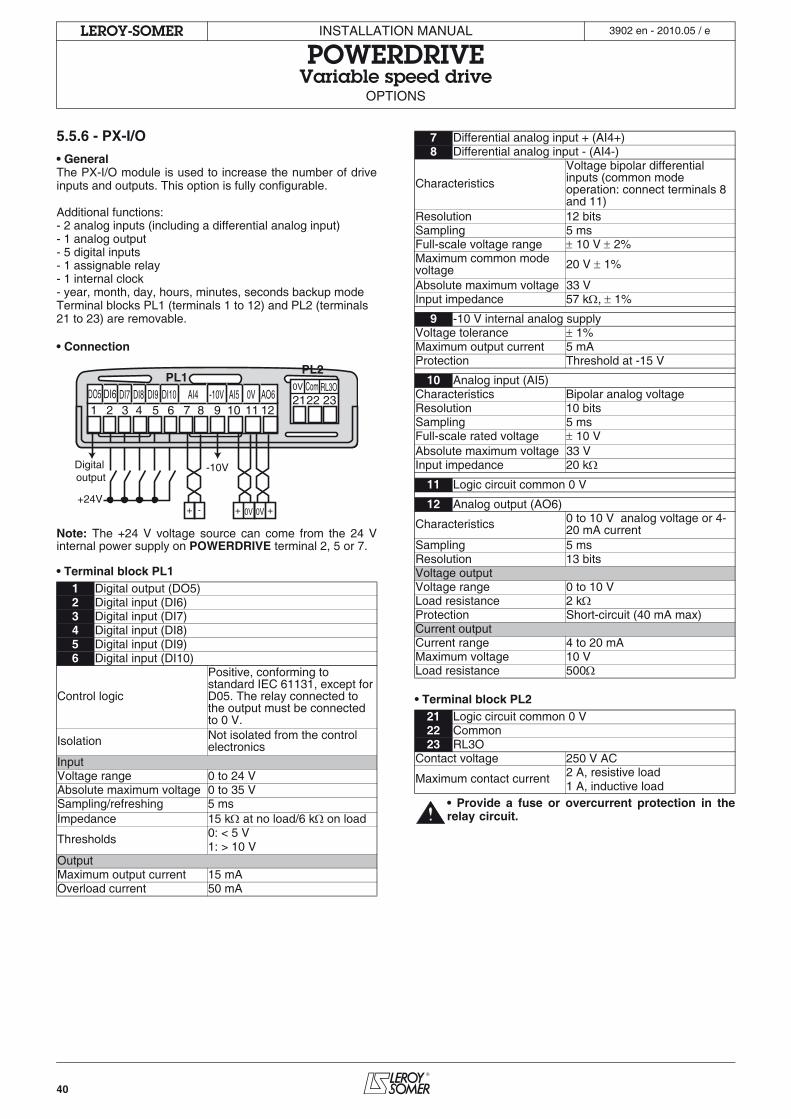
40
INSTALLATION MANUAL
POWERDRIVEVariable speed drive
OPTIONS
LEROY-SOMER 3902 en - 2010.05 / e
5.5.6 - PX-I/O
• GeneralThe PX-I/O module is used to increase the number of driveinputs and outputs. This option is fully configurable.
Additional functions:- 2 analog inputs (including a differential analog input)- 1 analog output- 5 digital inputs- 1 assignable relay- 1 internal clock- year, month, day, hours, minutes, seconds backup modeTerminal blocks PL1 (terminals 1 to 12) and PL2 (terminals 21 to 23) are removable.
• Connection
Note: The +24 V voltage source can come from the 24 Vinternal power supply on POWERDRIVE terminal 2, 5 or 7.
• Terminal block PL1
• Terminal block PL2
• Provide a fuse or overcurrent protection in therelay circuit.
1 Digital output (DO5)2 Digital input (DI6)3 Digital input (DI7)4 Digital input (DI8)5 Digital input (DI9)6 Digital input (DI10)
Control logic
Positive, conforming to standard IEC 61131, except for D05. The relay connected to the output must be connected to 0 V.
Isolation Not isolated from the control electronics
InputVoltage range 0 to 24 VAbsolute maximum voltage 0 to 35 VSampling/refreshing 5 msImpedance 15 k at no load/6 k on load
Thresholds 0: < 5 V1: > 10 V
OutputMaximum output current 15 mAOverload current 50 mA
1 2 3 4 5 6 7 8 9 10 11 12DO5 DI6 DI7 DI8 DI9 DI10 AI4 -10V AI5 0V AO6 2122
PL2PL1
230V Com RL3O
+ - +0V+ 0V
Digital output
+24V
-10V
7 Differential analog input + (AI4+)8 Differential analog input - (AI4-)
Characteristics
Voltage bipolar differential inputs (common mode operation: connect terminals 8 and 11)
Resolution 12 bitsSampling 5 msFull-scale voltage range 10 V 2%Maximum common mode voltage 20 V 1%
Absolute maximum voltage 33 VInput impedance 57 k , 1%
9 -10 V internal analog supplyVoltage tolerance 1%Maximum output current 5 mAProtection Threshold at -15 V
10 Analog input (AI5)Characteristics Bipolar analog voltageResolution 10 bitsSampling 5 msFull-scale rated voltage 10 VAbsolute maximum voltage 33 VInput impedance 20 k
11 Logic circuit common 0 V
12 Analog output (AO6)
Characteristics 0 to 10 V analog voltage or 4-20 mA current
Sampling 5 msResolution 13 bitsVoltage outputVoltage range 0 to 10 VLoad resistance 2 kProtection Short-circuit (40 mA max)Current outputCurrent range 4 to 20 mAMaximum voltage 10 VLoad resistance 500
21 Logic circuit common 0 V22 Common23 RL3O
Contact voltage 250 V AC
Maximum contact current 2 A, resistive load1 A, inductive load
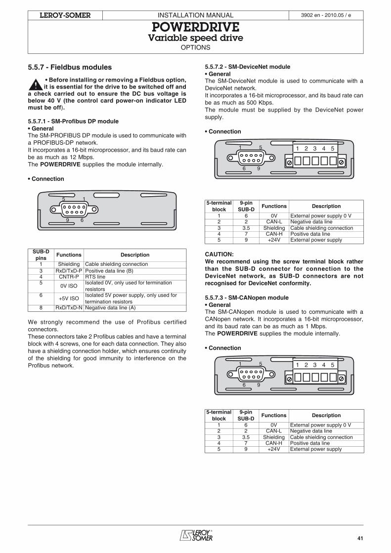
41
INSTALLATION MANUAL
POWERDRIVEVariable speed drive
OPTIONS
LEROY-SOMER 3902 en - 2010.05 / e
5.5.7 - Fieldbus modules
• Before installing or removing a Fieldbus option,it is essential for the drive to be switched off and
a check carried out to ensure the DC bus voltage isbelow 40 V (the control card power-on indicator LEDmust be off).
5.5.7.1 - SM-Profibus DP module• GeneralThe SM-PROFIBUS DP module is used to communicate witha PROFIBUS-DP network.It incorporates a 16-bit microprocessor, and its baud rate canbe as much as 12 Mbps.The POWERDRIVE supplies the module internally.
• Connection
We strongly recommend the use of Profibus certifiedconnectors.These connectors take 2 Profibus cables and have a terminalblock with 4 screws, one for each data connection. They alsohave a shielding connection holder, which ensures continuityof the shielding for good immunity to interference on theProfibus network.
5.5.7.2 - SM-DeviceNet module• GeneralThe SM-DeviceNet module is used to communicate with aDeviceNet network.It incorporates a 16-bit microprocessor, and its baud rate canbe as much as 500 Kbps.The module must be supplied by the DeviceNet powersupply.
• Connection
CAUTION:We recommend using the screw terminal block ratherthan the SUB-D connector for connection to theDeviceNet network, as SUB-D connectors are notrecognised for DeviceNet conformity.
5.5.7.3 - SM-CANopen module• GeneralThe SM-CANopen module is used to communicate with aCANopen network. It incorporates a 16-bit microprocessor,and its baud rate can be as much as 1 Mbps.The POWERDRIVE supplies the module internally.
• Connection
SUB-D pins
Functions Description
1 Shielding Cable shielding connection3 RxD/TxD-P Positive data line (B)4 CNTR-P RTS line5
0V ISOIsolated 0V, only used for termination resistors
6+5V ISO
Isolated 5V power supply, only used for termination resistors
8 RxD/TxD-N Negative data line (A)
15
69
5-terminal block
9-pin SUB-D
Functions Description
1 6 0V External power supply 0 V2 2 CAN-L Negative data line3 3.5 Shielding Cable shielding connection4 7 CAN-H Positive data line5 9 +24V External power supply
5-terminal block
9-pin SUB-D
Functions Description
1 6 0V External power supply 0 V2 2 CAN-L Negative data line3 3.5 Shielding Cable shielding connection4 7 CAN-H Positive data line5 9 +24V External power supply
1 2 3 4 551
96
1 2 3 4 551
96
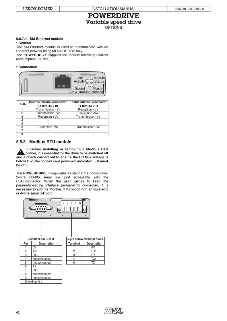
42
INSTALLATION MANUAL
POWERDRIVEVariable speed drive
OPTIONS
LEROY-SOMER 3902 en - 2010.05 / e
5.5.7.4 - SM-Ethernet module• GeneralThe SM-Ethernet module is used to communicate with anEthernet network using MODBUS TCP only.The POWERDRIVE supplies the module internally (currentconsumption 280 mA).
• Connection
5.5.8 - Modbus RTU module
• Before installing or removing a Modbus RTUoption, it is essential for the drive to be switched off
and a check carried out to ensure the DC bus voltage isbelow 40V (the control card power-on indicator LED mustbe off).
The POWERDRIVE incorporates as standard a non-isolated2-wire RS485 serial link port accessible with theRJ45 connector. When the user wishes to keep theparameter-setting interface permanently connected, it isnecessary to add the Modbus RTU option with an isolated 2or 4-wire serial link port.
RJ45Disable internal crossover
(# mm.43 = 0)Enable internal crossover
(# mm.43 = 1)1 Transmission +Ve Reception +Ve2 Transmission -Ve Reception -Ve3 Reception +Ve Transmission +Ve4 - -5 - -6 Reception -Ve Transmission -Ve7 - -8 - -
ModuleStatus
Link/Activity
Speed(On = 100Mbs)
FlashAccess
Female 9-pin Sub DPin Description123456789Shielding: 0 V
0VTX\RX\not connectednot connectedTXRXnot connectednot connected
5-pin screw terminal blockTerminal Description
12345
0VRX\RXTX\TX
1 2 3 4 55 1
9 6
43
INSTALLATION MANUAL
POWERDRIVEVariable speed drive
MAINTENANCE
LEROY-SOMER 3902 en - 2010.05 / e
6 - MAINTENANCE• All work relating to installation, commissioningand maintenance must be carried out by
experienced, qualified personnel.• When a trip detected by the drive causes it to
switch off, fatal residual voltages remain at the outputterminals and in the drive.
• Before carrying out any work, disconnect and lockthe drive power supply and wait at least 10 minutes toensure that the capacitors have discharged.
• Ensure that the DC bus voltage is below 40 Vbefore carrying out any work (the control card power-onindicator LED must be off, see section 5.5.1).
• During maintenance operations performed withthe drive switched on, the operator must stand on aninsulated surface which is not connected to earth.
• During work on a motor or its power supplycables, check that the power supply of thecorresponding drive is disconnected and locked.
• All protective covers must remain in place duringtests.
• After connecting the power, reposition the cablebush plates, which may be done at the back of thecabinet, to prevent the entry of foreign bodies.
There are very few maintenance and repair operations onPOWERDRIVE drives to be performed by the user. Regularservicing operations and simple methods for checking thatthe drive is operating correctly are described below.
6.1 - CarePrinted circuits and the drive components do not normallyrequire any maintenance. Contact your vendor or the nearestapproved repair company in the event of a problem.CAUTION:Do not dismantle the printed circuits while the drive isstill under warranty, as this would then immediatelybecome null and void.Do not touch the integrated circuits or the microprocessoreither with your fingers or with materials which are charged orlive. Earth yourself, as well as the workbench or the solderingiron, when performing any work on the circuits.From time to time, with the drive powered-down, check thatthe power connections are correctly tightened. The doorfilters must be checked and changed regularly according totheir condition.
6.2 - StorageIf the drive has been stored for more than 12 months, it isessential to switch it on for 24 hours (power and control), andrepeat this operation every 6 months.
6.3 - Exchanging productsCAUTION:Products must be returned in their original packaging or,if this is not possible, in similar packaging, to preventtheir being damaged. Otherwise, replacement underwarranty could be refused.
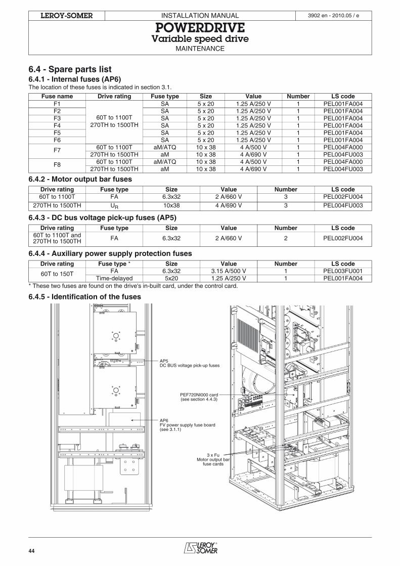
44
INSTALLATION MANUAL
POWERDRIVEVariable speed drive
MAINTENANCE
LEROY-SOMER 3902 en - 2010.05 / e
6.4 - Spare parts list6.4.1 - Internal fuses (AP6)The location of these fuses is indicated in section 3.1.
6.4.2 - Motor output bar fuses
6.4.3 - DC bus voltage pick-up fuses (AP5)
6.4.4 - Auxiliary power supply protection fuses
* These two fuses are found on the drive's in-built card, under the control card.
6.4.5 - Identification of the fuses
Fuse name Drive rating Fuse type Size Value Number LS codeF1
60T to 1100T270TH to 1500TH
SA 5 x 20 1.25 A/250 V 1 PEL001FA004F2 SA 5 x 20 1.25 A/250 V 1 PEL001FA004F3 SA 5 x 20 1.25 A/250 V 1 PEL001FA004F4 SA 5 x 20 1.25 A/250 V 1 PEL001FA004F5 SA 5 x 20 1.25 A/250 V 1 PEL001FA004F6 SA 5 x 20 1.25 A/250 V 1 PEL001FA004
F7 60T to 1100T aM/ATQ 10 x 38 4 A/500 V 1 PEL004FA000270TH to 1500TH aM 10 x 38 4 A/690 V 1 PEL004FU003
F8 60T to 1100T aM/ATQ 10 x 38 4 A/500 V 1 PEL004FA000270TH to 1500TH aM 10 x 38 4 A/690 V 1 PEL004FU003
Drive rating Fuse type Size Value Number LS code60T to 1100T FA 6.3x32 2 A/660 V 3 PEL002FU004
270TH to 1500TH UR 10x38 4 A/690 V 3 PEL004FU003
Drive rating Fuse type Size Value Number LS code60T to 1100T and 270TH to 1500TH FA 6.3x32 2 A/660 V 2 PEL002FU004
Drive rating Fuse type * Size Value Number LS code
60T to 150T FA 6.3x32 3.15 A/500 V 1 PEL003FU001Time-delayed 5x20 1.25 A/250 V 1 PEL001FA004
AP5DC BUS voltage pick-up fuses
PEF720NI000 card(see section 4.4.3)
AP6FV power supply fuse board(see 3.1.1)
3 x FuMotor output bar
fuse cards

45
INSTALLATION MANUAL
POWERDRIVEVariable speed drive
MAINTENANCE
LEROY-SOMER 3902 en - 2010.05 / e
Notes

46
INSTALLATION MANUAL
POWERDRIVEVariable speed drive
MAINTENANCE
LEROY-SOMER 3902 en - 2010.05 / e

47
INSTALLATION MANUAL
POWERDRIVEVariable speed drive
MAINTENANCE
LEROY-SOMER 3902 en - 2010.05 / e

MOTEURS LEROY-SOMER 16015 ANGOULÊME CEDEX - FRANCE
338 567 258 RCS ANGOULÊMELimited company with capital of 62,779,000 €
www.leroy-somer.com