VARMECA - 20 - Leroy-Somer - 20 Variable speed motor or geared motor LEROY-SOMER 3481 - 07.2005 / f...
20
This manual is to be given to the end user en VARMECA - 20 Variable speed motor or geared motor Installation and maintenance 3481 - 07.2005 / f 20
Transcript of VARMECA - 20 - Leroy-Somer - 20 Variable speed motor or geared motor LEROY-SOMER 3481 - 07.2005 / f...

This manual is to be given
to the end user
en
VARMECA - 20
Variable speed motor or geared motor
Installation and maintenance
3481 - 07.2005 / f
20
22
INSTALLATION AND MAINTENANCE
VARMECA - 20
Variable speed motor or geared motor
LEROY-SOMER
3481 - 07.2005 / f
NOTE
LEROY-SOMER reserves the right to modify the characteristics of its products at any time in order to incorporate the latest tech-nological developments. The information contained in this document may be therefore changed without prior notice.
CAUTION
For the user’s safety, this VARMECA 20 must be connected to a proper earthing ( terminal).
If the accidental starting of the installation is likely to cause a risk to the personnel or to the machines being driven, it is necessary to supply the equipment via a circuit-breaking device (power contactor) which can be controlled via an external safety system (emergency stop, detection of errors on the installation).
VARMECA 20 is fitted with safety devices which in case of a fault may control its stopping and consequently the motor stopping. This motor itself can be also subject to stopping as result of the mechanical blocking. Finally, the voltage fluctuations, in particular the power cuts, may also cause the motor stopping.
The removal of the shutdown causes can lead to a restart which may be dangerous for certain machines or installations, espe-cially for those which must comply with appendix 1 of decree no. 902.767 of 29
th
July, 1992 on safety.
In such cases, it is important for the user to take the appropriate precautions against the motor restarting after an unscheduledmotor stopping. The variable speed drive is designed to be able to supply with power a motor and the driven machine aboveits rated speed. If the motor or the machine are not mechanically designed to withstand such speeds, the user may be exposed to a seriousrisk due to their mechanical deterioration. It is important for the user to check, before setting a high speed, if the installation canwithstand it.The variable speed drive making the object of this manual is a component designed to be integrated into an installation or into anelectrical machine and it can under no circumstances be considered in any case a safety device. It is therefore the responsibilityof the machine manufacturer, the installation designer or the user to take the necessary precautions in order to ensure that theinstallation complies with the standards in force and to provide any devices required to ensure the safety of the equipment andpersonnel.
LEROY-SOMER declines all responsibility in case the above mentioned recommendations are not observed.

23
INSTALLATION AND MAINTENANCE
VARMECA - 20
Variable speed motor or geared motor
LEROY-SOMER
3481 - 07.2005 / f
en
• Throughout this manual the symbol warns of the consequences arising from the misuse of the
variable speed drive, since the electrical risks may leadto material damages or to body injuries, as well as to firehazards.
1 - General
Depending on their degree of protection, VARMECA - 20motors may contain, during their operation, live parts that arepowered up, which may be moving or rotating, as well as hotsurfaces. The improper removal of the protection devices, aninadequate use, a faulty installation or an inappropriatehandling could represent a serious risk to the equipment, theanimals and the personnel.For further information, read this documentation.All the works related to the transportation, installation,commissioning and maintenance must be performed by aqualified and authorised personnel (CEI 364 or CENELECHD 384, or DIN VDE 010, as well as the national provisionsregarding the installation and the accident prevention).Within the scope of these basic safety instructions, qualifiedpersonnel means persons having competence as regards theinstallation, the assembling, the commissioning and theproduct exploitation, and possessing the relevantqualifications.
2 - Use
VARMECA - 20 motors are components designed to beintegrated into installations or electrical machines.In case of integration into a machine, their commissioning isforbidden if the compliance of the machine with the provisionsof the Directive 89/392/CEE (machine directive) has not beenchecked. It is also necessary to observe the EN 60204standard stipulating mainly that the electrical actuators (whichinclude the variable speed drives ) cannot be considered ascircuit-breaking devices and certainty not as isolatingswitches.Their commissioning is not allowed if the provisions of theElectromagnetic Compatibility Directive (89/336/CEE,amended by 92/31/CEE) are not observed. VARMECA - 20motors meet the requirements of the Low Voltage Directive73/23/CEE, amended by 93/68/CEE. The harmonisedstandards of the DIN VDE 0160 series along with the VDE0660 standard, part 500 and EN 60146/VDE 0558 areapplicable to them.The technical characteristics and the instructions concerningthe connection conditions specified on the nameplate and inthe documentation provided must be observed.
3 - Transportation, storage
All the instructions concerning the correct transportation,storage and handling must be observed. The climatic conditions specified in the technical manual mustbe observed.
4 - Installation
The equipment installation and cooling must comply with theprovisions of the documentation supplied with the product.VARMECA - 20 motors must be protected against anyexcessive stress. In particular, the parts must not bedamaged and/or the clearances between components mustnot be changed during the transportation and the handling.Do not touch the electronic components and the contactparts.VARMECA - 20 motors contain parts which are sensitive toelectrostatic stresses and may be easily damaged in case ofan inadequate handling. The electrical components must notbe exposed to mechanical damage or destruction (otherwise,your health is at risk!).
5 - Electrical connection
When works are performed on variable speed drives whichare powered up, the national provisions related to theprevention of accidents must be observed. The electrical installation must be executed according to theapplicable provisions (for example, conductor section,protection by fused short-circuit, connection of the protectionconductor). More detailed information is given in the manual.The documentation accompanying VARMECA - 20 motorscontains the instructions for an installation which meets theelectromagnetic compatibility requirements, such asscreening, earthing, presence of filters and adequateinsertion of cables and conductors. These instructions mustbe observed in all cases, even if VARMECA - 20 motors carrythe CE mark. The observation of the limit values imposed bythe legislation on CEM is the responsibility of the installationor machine manufacturer.
6 - Operation
The installations with built-in VARMECA - 20 motors must befitted with additional protection and monitoring devices as laiddown in the safety provisions in force, such as the law ontechnical equipment, the provisions on accident prevention,etc. The modification of VARMECA - 20 motors by means ofthe control software are admitted.The active parts of the device and the live power connectionsmust not be touched immediately after the powering-down ofthe VARMECA - 20 motors, as the capacitors may still beloaded. In this regard the warnings attached to VARMECA -20 motors must be observed.During the operation, all the doors and protective devicesmust be kept in place.
7 - Maintenance and servicing
Refer to the manufacturer’s documentation
SAFETY AND OPERATING INSTRUCTIONS RELATED TO VARIABLE SPEED DRIVES (According to the low voltage directive 73/23/CEE amended by 93/68/CEE)

INSTALLATION AND MAINTENANCE
VARMECA - 20
Variable speed motor or geared motor
CONTENTS
LEROY-SOMER
3481 - 07.2005 / f
24
1 - GENERAL INFORMATION ................................................................................................................................. 25
1.1 - General principle............................................................................................................................................... 251.2 - Product name.................................................................................................................................................... 251.3 - Characteristics .................................................................................................................................................. 251.4 - Environment...................................................................................................................................................... 271.5 - Radio-frequency interference............................................................................................................................ 271.6 - Definition of cables and protection devices ...................................................................................................... 301.7 - UL conformity.................................................................................................................................................... 301.8 - Sizes and weight............................................................................................................................................... 30
2 -INSTALLATION.................................................................................................................................................... 31
2.1 - General information .......................................................................................................................................... 312.2 - Support reversing.............................................................................................................................................. 312.3 - Adjustment of MINI DIP .................................................................................................................................... 31
3 - CONNECTIONS .................................................................................................................................................. 32
3.1 - Wiring precautions ............................................................................................................................................ 323.2 - Earth wiring ....................................................................................................................................................... 323.3 - Terminal blocks................................................................................................................................................. 333.4 - Diagram based on the standard configuration .................................................................................................. 343.5 - Power supply and control of the FCR brake motors ........................................................................................ 343.6 - Brake rectified voltage depending on the power supply network...................................................................... 353.7 - Case of power supply of 2 motors with or without brake in parallel with a single VARMECA ......................... 353.8 - Diagram of the SO VMA and VMA ESFR options ............................................................................................ 36
4 - COMMISSIONING ............................................................................................................................................... 37
4.1 - Run command................................................................................................................................................... 374.2 - Speed control.................................................................................................................................................... 37
5 - FAULTS - DIAGNOSTIC ..................................................................................................................................... 37
6 - MAINTENANCE .................................................................................................................................................. 38
6.1 - Maintenance ..................................................................................................................................................... 386.2 - Measurements .................................................................................................................................................. 38
7 - OPERATION EXTENSION.................................................................................................................................. 39
7.1 - Speed control knob option (B) .......................................................................................................................... 397.2 - Control knob with integrated run-stop control option (B.MA) ............................................................................ 397.3 - Control knob with forward/reverse/stop control option (B MAVAR) .................................................................. 397.4 - Internal speed control option (CVI VMA20) ...................................................................................................... 397.5 - Braking resistor option (RF100 - RF200) .......................................................................................................... 397.6 - External braking resistor option (RF - BRR - 800 - 200) ................................................................................... 397.7 - Power supply and electromechanical brake control option (SO VMA) ............................................................. 407.8 - Additional input/output interface and sequential brake control option (VMA ESFR)......................................... 407.9 - Parameter-setting micro-console option (CDC-VMA20) ................................................................................... 407.10 - Parameter-setting software option (PEGASE VMA 20) .................................................................................. 407.11 - CEM filter option (FLT VMA21M).................................................................................................................... 407.12 - CEM filter option (FLT VMA20)....................................................................................................................... 407.13 - Fielbus option.................................................................................................................................................. 40

25
INSTALLATION AND MAINTENANCE
VARMECA - 20
Variable speed motor or geared motor
GENERAL INFORMATION
LEROY-SOMER
3481 - 07.2005 / f
en
1 - GENERAL INFORMATION
1.1 - General principle
VARMECA - 20 is the physical association of a three phase asynchronous motor and of an integrated variable speed drive.The motor allows all kinds of assembling arrangements (foot or flange) and can be combined with standard geared motors fromthe LEROY-SOMER range.In the standard version, the variable speed drive with integrated control does not require any connection other than the powersupply.The options may be used to broaden the applications range of VARMECA - 20.Due to the advanced technology of the IGBT power module, very high technology and reduced noise levels are possible.
1.2 - Product name
1.3 - Characteristics
1.3.1 - Power characteristics
Single phase
Three phase
* 2.2 kW maximum for the 230V mains supply.
VARMECA - 20Single phase power supply 200/240V ± 10% Three phase power supply 200/240V ± Three phase power supply 400/480V ±
VMA Rating Power (kW) VMA Rating Power (kW) VMA Rating Power (kW)
A or B 21M - 025 0.25 A or B 21TL - 025 0.25 A or B 21T - 025 0.25A or B 21M - 037 0.37 A or B 21TL - 037 0.37 A or B 21T - 037 0.37A or B 21M - 055 0.55 A or B 21TL - 055 0.55 A or B 21T - 055 0.55A or B 21M - 075 0.75 A or B 21TL - 075 0.75 A or B 21T - 075 0.75A or B 22M - 090 0.9 A or B 22TL - 090 0.9 A or B 21T - 090 0.9A or B 22M - 110 1.1 A or B 22TL - 110 1.1 A or B 21T - 110 1.1A or B 22M - 150 1.5 A or B 22TL - 150 1.5 A or B 22T - 150 1.5
A or B 22TL - 180 1.8 A or B 22T - 180 1.8A or B 22TL - 220 2.2 A or B 22T - 220 2.2
A or B 22T - 300 3A or B 22T - 400 4
OptionsName Description
B Integrated speed control knobBMA Speed control knob and integrated run-stop control knob
BMAVAR Speed control knob and integrated forward/reverse/stop control knobCVI VMA 20 Integrated speed control
RF100 - RF200 Braking resistor with a power of 100 and 200WRF - BRR - 800 - 200 Braking resistor with a power of 800W - External assembling
SO VMA Power supply and fixed brake control - (only three phase mains supply of 400-480V )VMA ESFR Additional input/output interface and sequential brake control
CDC VMA 20 VARMECA 20 micro-consolePEGASE VMA 20 VARMECA 20 PC software
VMA COM PB Fieldbus: PROFIBUS DPVMA COM IS Fieldbus: INTERBUS SVMA COM DT Fieldbus: DEVICENETVMA COM CN Fieldbus: CAN OPENFLT VMA 21 M CEM filter for residential environment - Internal assembling (only for VMA21M )FLT VMA 20 CEM filter for residential environment - Internal assembling for VMA22M/21T-TL/22T-TL
Power supply Single phase mains supply 200V -10 % to 240V +10 % 50-60HzOutput voltage From 0V to the power supply voltagePower range 0.25 - 0.37 - 0.55 - 0.75 - 0.9 - 1.1 - 1.5 kWMaximum number of power-ups by hour 10
Power supply Three phase mains supply 200V -10 % to 480V +10 %, 50 - 60 Hz ± 5 %Output voltage From 0V to the power supply voltagePower range 0.25 - 0.37 - 0.55 - 0.75 - 0.9 - 1.1 - 1.5 - 1.8 - 2.2* - 3 - 4 kWMaximum number of power-ups by hour limited
• This manual describes the characteristics and the installation of VARMECA A20 and B20.• VARMECA A20 and B20 are designed to operate in an industrial environment.• If the run command has been enabled, the motor starts as soon as it is powered up.

26
INSTALLATION AND MAINTENANCE
VARMECA - 20
Variable speed motor or geared motor
GENERAL INFORMATION
LEROY-SOMER
3481 - 07.2005 / f
1.3.2 - Characteristics and functions
* Adjustment by mini DIP (see par. 2.3)** Accessible by the parmeter-setting option (see VARMECA 20 manual - Parameter-setting).
CHARACTERISTICS VARMECA - 20
Overcharge 150 % In during 40s 10 times by hourMotor frequency variation range - from 12 to 80Hz at constant torque (the factory setting can be modified by means of the
parameter-setting option)- from 12 to 50 Hz for general applications (the factory setting can be modified by means of the parameter-setting option)- from 6 to 220 Hz (VARMECA A20) or from 6 to 100 Hz (VARMECA B20)**
Efficiency 97.5 % x motor efficiency
PILOT CONTROL VARMECA - 20
Speed reference • Analogue reference (0V or 4mA = minimum speed)(10V or 20mA = maximum speed)
- 0 - 10V by integrated potentiometer (option B)- 0 - 10V by remote potentiometer option- 0 - 10V by external reference*- 4 - 20mA by external reference*- Reference by internal potentiometer (option CVI - VMA 20)- Maximal speed limitation by the internal potentiometer (option CVI-VMA 20)
• Digital reference- 1 to 4 preset speeds**
• By fieldbusSpeed regulation Regulation of a reference with integrated PI loop** (only VARMECA A20)
Characteristics of the PI sensor: signal 0 - 10V ou 4 - 20 mA*Run/Stop • By power supply
• By remote volt-free contact• By integrated run/stop control (option BMA)• BY fieldbus
Forward/Reverse • By internal connection to the terminal block• By remote volt-free contact• By integrated forward/reverse/stop control (option BMAVAR)• By fieldbus
Stop mode • By ramp (by volt-free contact or integrated run/stop control)• Freewheel stop (by cutting the power supply)**• Freewheel stop (by volt-free contact or integrated run/stop control)**• By electromechanical brake (option SO VMA or VMA ESFR)
Ramps • Selection by volt-free contact of the acceleration and deceleration ramps 2s or 5s(factory setting 5s for F max 80 Hz)
• Ramps adjustable from 0 to 100s (VARMECA A20) or from 0 to 40s (VARMECA B20)**Fieldbus PROFIBUS DP, INTERBUS S, DEVICENET, CAN OPEN
SIGNALLING VARMECA - 20
Visualisation with options:- B- BMA- BMAVAR- CVIVMA20
By indicator lamps• Steady green: mains supply presence• Flashing green: overcharge• Flashing green and red: current limitation• Flashing red: fault with or without voltage• Steady red: other fault
Relays • Variable speed drive fault (other possible assignments**)
volt-free contact - 1A - 250V - open contact, variable speed drive faulty or powered down
Analogue output • Speed image 0 - 10V, 3mA / Current image*** / Power image***• 0V = zero speed / 0V = 0A / 0V = 0 kW• 10V = maximum speed / 10V = 10A / 10V = 5 kW
*** only VARMECA A20 **
PROTECTIONS VARMECA - 20
Power • Powered up• Overvoltage• Overcharges :
- thermal variable speed drive and motor- blocked rotor protection
• Short-circuit- motor windings
Torque limitation • VARMECA B20 exclusively**Control • Short-circuit on 0 - 10V - 24V inputs or outputsFault reset • By powering down VARMECA

27
INSTALLATION AND MAINTENANCE
VARMECA - 20
Variable speed motor or geared motor
GENERAL INFORMATION
LEROY-SOMER
3481 - 07.2005 / f
en
1.4 - Environment characteristics
1.5 - Radio-frequency interference
1.5.1 - General
The variable speed drives use high-speed switches (transistors, semi-conductors) which switch high voltages (around 550V forthe three phase variable speed drives) at high frequencies (several kHz). This provides better efficiency and a low motor noise.
Therefore, they generate radio-frequency signals which may disturb the operation of other equipment or the measurements takenby the sensors:- due to high-frequency leakage currents which escape to earth via the leakage capacity of the variable speed drive/motor cableand that of the motor by the metal structures holding the motor.- by R.F. signal conduction or feedback on the power supply cable: conducted emissions,- by direct radiation near to the mains supply power cable or the variable speed drive/motor cable: radiated emissions.These phenomena are of direct interest to the user.The frequency range concerned (radio-frequency) does not disturb the energy distributor.
The conformity of the variable speed drive is assured only if the mechanical and electrical installation instructionsdescribed in this manual are observed.
Characteristics Level
Index of protection IP 65
Storage temperature -40 °C to +70 °C (CEI 68.2.3). According to the CEI 60068-2-1 standard.
Transport temperature -40 °C to +70 °C
Operating temperature -20 °C to +50 °C (with power derated by 1% per °C, above 40 °C)
Altitude
< 1000 m without derating.The maximum authorised altitude is of 4000 m, but above 1000 m, the continuous outputcurrent should be derated by 1% by additional 100m over 1000 m (e.g.: for an altitude of 3000m, derate by 20%).
Ambient humidity 95% without condensation
Humidity during storage 93%, 40 °C, 4 days
Vibrations- Unpacked product : 0.01 g
2
/Hz 1hr according to the CEI 60068-2-34 standard.- Sinusoidal vibration: 2-9 Hz 3.5 ms
-2
– 9-200 Hz 10 ms
-2
– 200-500 Hz 15 ms
-2
according to the CEI 60068-2-6 standard.
Shocks Packed product: 15 g, 6 ms, 500 times/direction in all 6 directions according to theCEI 60068-2-29 standard.
Immunity According to EN 61000-6-2
Conducted and radiated emissions According to EN 61000-6-4
UL standards According to UL 508 C (E211799)
IGENERAL INFORMATION & INSTALLATION

28
INSTALLATION AND MAINTENANCE
VARMECA - 20
Variable speed motor or geared motor
GENERAL INFORMATION
LEROY-SOMER
3481 - 07.2005 / f
1.5.2 - Electromagnetic compatibility (CEM)
CAUTION :The conformity of the variable speed drive is assured only if the mechanical and electrical installation instructions described in this manual are observed.
The second environment includes the industrial networks supplied with low voltage but which do not servebuildings for domestic use. The operation of a variable speed drive without RFI filter in such an environment may
cause interference on certain electronic appliances located close to the variable speed drive whose level of immunitymight not be compatible with the industrial conditions. It is impossible to filter the disturbed element, add an external RFIfilter.
ImmunityStandard Description Application Conformity
EN 61000-4-2 Electrostatic discharges Product casing Level 3 (industrial)
EN 61000-4-3Immunity standards for the radiated radio-frequency
Product casing Level 3 (industrial)
EN 61000-4-4 Fast transient burstControl cable Level 4 (hard industrial)Power cable Level 3 (industrial)
EN 61000-4-5 Surges
Power supply lines between phase and earth
Level 4
Power supply lines between phases
Level 3
Signal circuit to earth(see par. 1.5.5)
Level 2
EN 61000-4-6Generic immunity standards for the conducted radio-frequency
Control and power cables Level 3 (industrial)
EN 61000-6-1Generic immunity standards for the residential, commercial and light industrial environments
- In conformity
EN 61000-6-2Generic immunity standards for the industrial environment
- In conformity
EN 61800-3 Variable speed drive standards In conformity with the first and second environment
Emission
Standard Description Application
Conformity conditions according to the switching frequency
With RFI filter
Internal (standard)Integrable (option)
FLT VMA 21 MFLT VMA 20
EN 61800-3 Variable speed drive standards
Second environment with unrestricted distribution
(DENR)
≤
11 kHz
≤
11 kHz
Second environment with restricted distribution (DER)
≤
11 kHz
≤
11 kHz
First environment with unrestricted distribution (R)
NON
≤
11 kHz
First environment with restricted distribution (I)
≤
4 kHz
≤
11 kHz
EN 61000-6-3Generic emission standards for the residential, commercial and light industrial environments
A.C. mains supply NO
≤
11 kHz
EN 61000-6-4Generic emission standards for the industrial environment
A.C. mains supplyVMA 21T
≤
8 kHzVMA 22T
≤
4 kHz
≤
11 kHz
GENERAL INFORMATION & INSTALLATION
29
INSTALLATION AND MAINTENANCE
VARMECA - 20
Variable speed motor or geared motor
GENERAL INFORMATION
LEROY-SOMER
3481 - 07.2005 / f
en
1.5.3 - Earth leakage current
The earth leakage current may depend on the type of the RFIfilter used. VARMECA 20 is supplied with its filter integratedand cabled. The leakage current levels depend also on thevoltage and/or of the power supply frequency and of themotor dimension.In all cases in order to assure the conformity with theimmunity standards, o voltage limiting device is connected toearth. The shunt current is insignificant in normalcircumstances.
When the internal filter is disconnected apermanent earth connection must be provided or
any other appropriate measure must be taken in order toavoid any risk of electric shock in case of earthcontinuity loss.
1.5.3.1 - Use of leakage current detector (differential circuit breaker)
There are 3 types of detectors:1- AC type: which detects the AC faults. Not to be used withthe variable speed drives. 2- A type: which detect the AC faults and the pulsed DC faults(provided that the DC is cancelled out at least once by cycle).Only for use with single phase variable speed drives. 3 - B type: which detects the AC faults, the pulsed DC faultsand the smoothed DC faults.
Only this type is suitable foruse with nvariable speed drives.
Note:
In case of an external RTI filter, a delay of 50 ms mustbe applied in order not to take into account the accidentalfaults.
1.5.4 - Control cable immunity
The control cable immunity can be increased outsideVARMECA 20 by one of the following 2 methods: • The use of a shielded twisted pair cable with a shieldingconnected to earth on its circumference at less than 100 mmof VARMECA 20.• Running the cable through a ferrite ring at maximum 100mm from VARMECA 20.
Note:
Several control cables can pass through a singleferrite.
1.5.5 - Control circuit immunity when overvoltage occurs
The immunity to control circuit overvoltages or long cablelengths and connection to the outside of a building.The various variable speed drive input and output circuits arein compliance with the EN61000-6-2 (1kV) standard onovervoltages.
There are some exceptions, where the installation may beexposed to overvoltage peaks which exceed the levelsdetermined by the standard. This may be the case oflightning strikes or earth faults associated with long cable
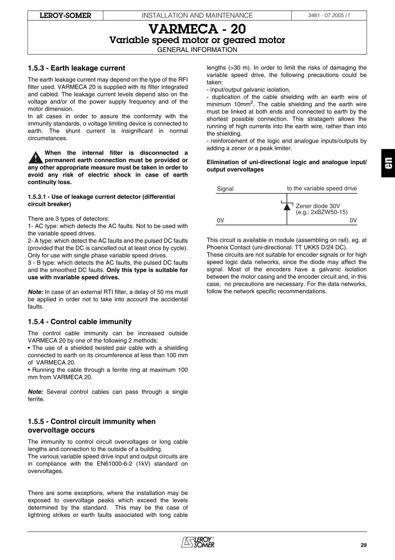
lengths (>30 m). In order to limit the risks of damaging thevariable speed drive, the following precautions could betaken:- input/output galvanic isolation,- duplication of the cable shielding with an earth wire ofminimum 10mm
2
. The cable shielding and the earth wiremust be linked at both ends and connected to earth by theshortest possible connection. This stratagem allows therunning of high currents into the earth wire, rather than intothe shielding. - reinforcement of the logic and analogue inputs/outputs byadding a zener or a peak limiter.
Elimination of uni-directional logic and analogue input/output overvoltages
This circuit is available in module (assembling on rail), eg. atPhoenix Contact (uni-directional: TT UKK5 D/24 DC).These circuits are not suitable for encoder signals or for highspeed logic data networks, since the diode may affect thesignal. Most of the encoders have a galvanic isolationbetween the motor casing and the encoder circuit and, in thiscase, no precautions are necessary. For the data networks,follow the network specific recommendations.
Zener diode 30V(e.g.: 2xBZW50-15)
Signal
0V 0V
to the variable speed drive

30
INSTALLATION AND MAINTENANCE
VARMECA - 20
Variable speed motor or geared motor
GENERAL INFORMATION
LEROY-SOMER
3481 - 07.2005 / f
1.6 - Definition of cables and protection devices
• It is the responsibility of the user to connect and provide protection for VARMECA 20 according to the legislationand regulation in force in the country of use. This is particularly important as regards the size of the cables, the
type and the rating of fuses, the earth or ground connection, the powering down, the fault settlement, the insulation andthe protection against overcurrents. • These tables are given for information only and must under no circumstances be used instead of the standards in force
.
• If a circuit-breaker is used, this must be of the motor circuit-breaker type (curve D).• The differential circuit-breaker must be of type B. A too high number of devices connected to a single differential circuit-breaker may switch it on. It is important to make sure that the differential protects only VARMECA 20.• Observe the sizes of the protection fuses.
Note:
• The mains supply current is a typical value which depends on the source impedance. The higher the impedance, the lower thecurrent.• The fuses (UL certified) are provided for installations able to provide maximum 5000A under 480V.
1.7 - UL conformity
1.7.1 - Specified mains supply
The variable speed drive may be incorporated in an installation which can deliver maximum 5000A rms at o voltage of maximum264Vca rms for 230V (TL) variable speed drives or of maximum 528Vca rms for 400V (T) variable speed drives.
1.7.2 - Cables
Only 60/75°C (140/167° F) class 1 copper cables should be used.
1.7.3 - Fuses
The UL conformity is assured if the fuses used are UL-listed, fast-blow fuses, (class CC up to 30A and class J up to 30A thereafter)with a rating as indicated in the table above, and if the symmetrical short-circuit current does not exceed 5kA. Example of fast-blow fuses: Limitron KTK de Bussman, Amp - trap ATM by Gould.
1.8 - Sizes and weight
P(kW)
Single phase power supply 230V Three phase power supply 230V Three phase power supply 400V
VMA ratingI
gI fusesCables
VMA ratingI
gI fuses Cables
VMA ratingI
gI fuses Cablesor circuit or circuit- or circuit-
breaker breaker breaker(A) (A) (mm2) (A) (A) (mm2) (A) (A) (mm2)
0.25 A or B 21M-025 3.5 8 1.5 A or B 21TL-025 2 4 1.5 A or B 21T-025 1 4 1.50.37 A or B 21M-037 4 10 1.5 A or B 21TL-037 3 6 1.5 A or B 21T-037 1.5 4 1.50.55 A or B 21M-055 4.5 10 1.5 A or B 21TL-055 4 6 1.5 A or B 21T-055 2 6 1.50.75 A or B 21M-075 7 16 2.5 A or B 21TL-075 5 8 1.5 A or B 21T-075 3 6 1.50.9 A or B 22M-090 9 16 2.5 A or B 22TL-090 5.5 10 1.5 A or B 21T-090 3.5 8 1.51.1 A or B 22M-110 11 20 2.5 A or B 22TL-110 6 10 1.5 A or B 21T-110 4 10 1.51.5 A or B 22M-150 14 25 2.5 A or B 22TL-150 7 16 2.5 A or B 22T-150 5 10 1.51.8 A or B 22TL-180 7.5 16 2.5 A or B 22T-180 5.5 10 2.52.2 A or B 22TL-220 8 16 2.5 A or B 22T-220 6 10 2.53 A or B 22T-300 7 16 2.54 A or B 22T-400 8 16 2.5
TypeSizes in mm Weight of
VARMECA (kg)
HJ J I II LJB3/B14 B5 B5
LS 71 L 181 216 75 94 8 8 34 4.2LS 80 L 191 216 75 94 12 12 39 4.2LS 90 S et L 201 216/230 75 94 12 32 32 4.2LS 100 L 206 230 75 94 12 12 33 4.2LS 112 M 206 230 75 94 12 12 33 4.2LS 112 MG 215 230 75 94 20 20 16.5 4.2
JLJ
HJ
I II

31
INSTALLATION AND MAINTENANCE
VARMECA - 20Variable speed motor or geared motor
INSTALLATION
LEROY-SOMER 3481 - 07.2005 / f
en
INSTALLATION & CONNECTIONS
2 - INSTALLATION• It is the responsibility of the owner or of the userto make sure that the installation, the operationand the maintenance of the modulator and of its
options are made in compliance with the legislationrelating to the safety of the equipment and personnel andwith the regulation in force in the country of use.
• Before carrying out any work, disconnect andlock the variable speed drive power supply and wait 2minutes to make sure that the single phase rangecapacitors are completely discharged.
• After connection, make sure that the seals arefirmly in place and that the screws and the cable glandsare watertight to ensure the IP 65 protection.
2.1 - General informationVARMECA - 20 is fitted to the machine like a standard motorby means of flanges or foots. The motor fan cools the whole assembly. Make sure that theventilation air inlet is not obstructed. The position of the potentiometer/cable gland supports isestablished when controlling, however they may be reversedif necessary.
2.2 - Reversing the supports1) Unscrew the 2 TORX 20 screws + slot and remove thecover.
2) Remove the control knob and the cable gland supportfastening screws (TORX 10 screw + slot).
3) Disconnect the P2 connector layer if the option ifconnected.
4) Reverse the option and cable gland supports.
5) Reconnect the layer to P2 of the printed circuit and put thefastening screws in their place.
6) Put the cover in place.
TORX 10 screw+ slot
3
STA
ND
AR
D C
ON
FIG
UR
AT
ION
12
34
56
78
91024V
5s
2s
24V10V
0V
1112
L1
L2
L3
PE
R1
R250
10k
VAL
IDA
TIO
NE
NA
BLE
FR
EIG
AG
E
0 - 10V4 - 20m
A
200V -10%
480V +10%
CA
UT
ION
A
TT
EN
TIO
N
AC
HT
UN
G B
efore m
ainten
ance
Avan
t interven
tion
Vo
r jeglich
em ein
griff
w
ait 2 min
utes
attend
re 2 min
utes
2 min
uten
warten
DE
FAU
TFA
ULT
ST
ÖR
UN
G
RE
SE
AU
SU
PP
LYN
ET
Z
AC
CE
LD
EC
EL
CO
NF
IGU
RA
TIO
N O
PT
ION
CO
NS
ULT
ER
LA
NO
TIC
E D
'INS
TAL
LA
TIO
N
SE
E IN
STA
LLATIO
N M
AN
UA
L
BIT
TE
INB
ET
RIE
BN
AH
ME
SE
HE
N
P2
4
5
STA
ND
AR
D C
ON
FIG
UR
AT
ION
12
34
56
78
91024V
5s
2s
24V10V
0V
1112
L1
L2
L3
PE
R1
R250
10k
VAL
IDA
TIO
NE
NA
BLE
FR
EIG
AG
E
0 - 10V4 - 20m
A
200V -10%
480V +10%
CA
UT
ION
A
TT
EN
TIO
N
AC
HT
UN
G B
efore m
ainten
ance
Avan
t interven
tion
Vo
r jeglich
em ein
griff
w
ait 2 min
utes
attend
re 2 min
utes
2 min
uten
warten
DE
FAU
TFA
ULT
ST
ÖR
UN
G
RE
SE
AU
SU
PP
LYN
ET
Z
AC
CE
LD
EC
EL
CO
NF
IGU
RA
TIO
N O
PT
ION
CO
NS
ULT
ER
LA
NO
TIC
E D
'INS
TAL
LA
TIO
N
SE
E IN
STA
LLATIO
N M
AN
UA
L
BIT
TE
INB
ET
RIE
BN
AH
ME
SE
HE
N
P2
2.3 - MINI DIP adjustmentsAllow the reference selection, the U/F law selection and the choice of the order on the terminal 2 analogue input. (see VARMECA-20 manual - Parameter-setting).
Factory adjustments
CAUTION :This handling must be made adequately and by a qualified and authorised personnel.
MINI DIP OFF ONK1 Reference Reference
Speed reference 4 - 20mA 0 - 10VK2
4 - 20mA 0 - 10VAnalogue inputterminal 2
K3 U/F Law U/F LawLoi U/F factory settings constant
ON
K3 K2
P2
P1
P3
K1
OFF
1 2 3 4 5 6 7 8 9
32
INSTALLATION AND MAINTENANCE
VARMECA - 20Variable speed motor or geared motor
CONNECTIONS
LEROY-SOMER 3481 - 07.2005 / f
3 - CONNECTIONS• All connection works must be performed inaccordance with the laws in force in the country in
which it is installed. This includes the earthing or thegrounding in order to make sure that no directlyaccessible part of the variable speed drive can beconnected to the mains supply voltage or to any othervoltage which may be dangerous. • The voltages existing on the cables or the mains supplyconnections, the motor, the braking resistor or the filtermay cause fatal electric shocks. Contract must beavoided in all circumstances. • The variable speed drive must be supplied with powervia a circuit-breaking device so that it can be powereddown in a safe manner.• The variable speed drive contains capacitors whichremain loaded at a fatal voltage, even if the power supplyhas been cut off. • Wait 2 minutes after powering down the variable speeddrive before removing the protection devices. • The variable speed drive must be protected againstovercharges and short-circuits. • It is vital to comply with the rating of the protectiondevices. • Connection exclusively by copper conductor.• Check to see if the voltage and the current of thevariable speed drive, the motor and the mains supply arecompatible. • After the variable speed drive operation, the heater maybe very hot, therefore avoid touching it.
3.1 - Wiring precautions• When VARMECA 20 is remotely controlled, avoid theparallel routing of the power cables and of the control cables.• All the remote control cables must be shielded and have asection between 0.22 mm2 and 1 mm2. The shielding mustbe connected to earth at both sides.
• VARMECA 20 has a positive logic configuration.The use of a variable speed drive with a control
system having different control logic may cause anaccidental starting of the motor. • In the variable speed drive the control circuits are isolated from the power circuits by a simple insulation.(CEI 664-1). The installer must ensure that the externalcontrol circuits are isolated against any human contact. • If the control circuits need to be connected to circuitscomplying with the SELV safety requirements, anadditional insulation must be inserted in order tomaintain the SELV classification.
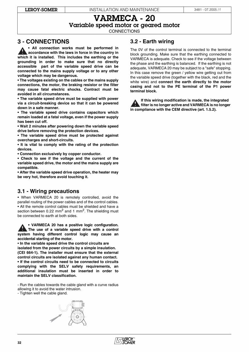
- Run the cables towards the cable gland with a curve radiusallowing it to avoid the water intrusion.- Tighten well the cable gland.
3.2 - Earth wiringThe 0V of the control terminal is connected to the terminalblock grounding. Make sure that the earthing connected toVARMECA is adequate. Check to see if the voltage betweenthe phase and the earthing is balanced. If the earthing is notadequate, VARMECA 20 may be subject to a "safe" stopping.In this case remove the green / yellow wire getting out fromthe variable speed drive (together with the black, red and thewhite wire) and connect the earth directly to the motorcasing and not to the PE terminal of the P1 powerterminal block.
If this wiring modification is made, the integrated filter is no longer active and VARMECA is no longer
in compliance with the CEM directive (art. 1.5.2).

33
INSTALLATION AND MAINTENANCE
VARMECA - 20Variable speed motor or geared motor
CONNECTIONS
LEROY-SOMER 3481 - 07.2005 / f
en
3.3 - Terminal blocks
3.3.1 - Terminal block integration
3.3.2 - P1 terminal block
Standard configuration
* Make sure that the signals connected to the controlterminals are voltage free.** VARMECA 20motors are delivered accompanied by a shunt. The inputs are thus validated for the forwarding.
3.3.3 - Connector P2
It allows the option connection by knob (B), Integrated run/stop (BMA), integrated forward/reverse/stop (BMAVAR),...
3.3.4 - Connector P3 of RS232 series link type
It allows the connection of the CDC VMA 20 micro-console orof a PC for the use of the PEGASE VMA 20 programmingsoftware or of the fieldbus option cards.
Ref.point Functions - CharacteristicsConnection of the mains supply protected phases
L1, L2 200V to 240V ± 10 %, 50-60Hz in single phaseL1, L2, L3 200V to 480V ± 10% 50-60Hz in three phase
PE Earth connection
R1, R2 Braking resistor connectionResistor minimum value = 180 Ohms
** 1Locking logic inputUnconnected terminals 1 and 3: locked driveConnected terminal 1 and 3: unlocked drive
2
Speed analogue output 0 to +10V, 3mA0V = zero speed10V = maximum speedAnalogue input: see VARMECA - 20 manual -Parameter-setting
3 Source +24V, 30mA (± 10 %)Common to terminal 10
4 Source +10V, 30mA (± 10 %)5 0V - Connected to the terminal block ground*
6Reference input 0 to +10V or 4-20mA0-10V: input impedance = 100 kOhms4-20mA: iinput impedance = 0.5 kOhms
7 Reverse/stop logic input** 8 Forward/stop logic input
** 9Ramp selection logic input1s(for 0 to 50Hz):unconnected terminals 9 and 10 3s (for 0 to 50Hz):conected terminals 9 and 10
10 Source +24V - 30mACommon to terminal 3
11, 12Fault relay - volt free contact 250V 1AOpen contact: powered down or in trip statusClosed contact: in operation
ON
K3 K2
P2
P1
P3
K1
OFF
1 2 3 4 5 6 7 8 9 10 11 12 L1 L2 L3 PE R+ R-
Control/Command Mains supply
M/N : 77b3000AP/N : VARMECA21S/N : 20106000748

34
INSTALLATION AND MAINTENANCE
VARMECA - 20Variable speed motor or geared motor
CONNECTIONS
LEROY-SOMER 3481 - 07.2005 / f
3.4.1 - VARMECA - 20 single phase connection 3.4.2 - VARMECA - 20 three phase connection
12
3
4
L1L2L3
R1
R2
PE56789
10
11
12
Analogue outputLocking
QS : Fused isolatorAU : Emergency stopSB1 : Powering-down knobSB2 : Powering-up knob
Controlpotentiometer0V
+10V
+24V
ReverseForwardRamp selection+24V
Fault relay
VMA 20QSKM1
SB2 KM1
SB1
AU
Remote controlpower supply
KM1
Brakeresistor
12
3
4
L1L2L3
R1
R2
PE56789
10
11
12
Analogue outputLocking
QS : Fused isolatorAU : Emergency stopSB1 : Powering-down knobSB2 : Powering-up knob
Controlpotentiometer0V
+10V
+24V
ReverseForwardRamp selection+24V
Fault relay
VMA 20QS KM1
SB2 KM1
SB1
AU
Remote controlpower supply
KM1
Brakeresistor
3.5 - Power supply and control of the FCR brake motors
3.5.1 - Power supply of the fixed control integrated brake (SO VMA option)
- The brake in supplied with power by means of a rectifier fixed on the SO VMA connection card. The connection is made according to the factory configuration.- The rectifier is supplied with power by a mains supply phase and by the motor star point. - No VARMECA parameter-setting is necessary.- The brake putting on takes place since the validation of the VARMECA run command. The brake release is effective after a stop command, at the and of the deceleration ramp or on the mains supply circuit-breaking.
3.5.2 - Power supply of the sequential control integrated brake (VMA ESFR option)
- The brake is supplied with power by means of a rectifier and of a static relay fixed on the VMA ESFR connection card. The connection is made according to the factory configuration.-The rectifier is supplied with power by two mains supply phases.- The brake is controlled starting with a sequence adjustable by means of the VARMECA parameters.
3.5.3 - Separated power supply
The brake is supplied with power and controlled by an external source.
3.4 - Diagram based on the standard configuration

35
INSTALLATION AND MAINTENANCE
VARMECA - 20Variable speed motor or geared motor
CONNECTIONS
LEROY-SOMER 3481 - 07.2005 / f
en
3.7 - Case of power supply of 2 motors with or without brake in parallel with a single VARMECA
3.7.1 - VARMECA size determination must be made for the total motor power
- It is necessary to use the 4 cable gland flabby option in order to facilitate the wiring of the second motor.
3.7.2 - The connection of the second motor is to be made on the located terminal block U, V, W and PE of the SO VMA and VMA ESFR options.
3.7.3 - Connection of the second motor brake
- With the SO VMA option, the rectifier is supplied with power between the motor star point and a mains supply phase coming from the terminal F1 of the SO VMA option.
Terminal F1 of SO VMA option
- With the VMA ESFR option, the rectifier is supplied with power between 2 mains supply phases and the static relay, connection to be made on the terminals F1 and F2 of the VMA ESFR option.
Terminals F1 and F2 of VMA ESFR option
F1
F1F2
3.6 - Brake rectified voltage depending on the mains supply
NR : Not performed, provide a separate power supply.
Mains supply VMA rating Power (kW) FCR brake voltageSO VMA option VMA ESFR option (only VMA B20)
Single phase power supply200/240V
A or B 21M-025 0.25
NR 180V DC
A or B 21M-037 0.37A or B 21M-055 0.55A or B 21M-075 0.75A or B 22M-090 0.9A or B 22M-110 1.1A or B 22M-150 1.5
Three phase power supply 200/240V
A or B 21TL-025 0.25
NR 180V DC
A or B 21TL-037 0.37A or B 21TL-055 0.55A or B 21TL-075 0.75A or B 22TL-090 0.9A or B 22TL-110 1.1A or B 22TL-150 1.5A or B 22TL-180 1.8A or B 22TL-220 2.2
Three phase power supply400/480V
A or B 21T-025 0.25
120V DC 180V DC
A or B 21T-037 0.37A or B 21T-055 0.55A or B 21T-075 0.75A or B 21T-090 0.9A or B 21T-110 1.1A or B 22T-150 1.5A or B 22T-180 1.8A or B 22T-220 2.2A or B 22T-300 3A or B 22T-400 4 100V DC

36
INSTALLATION AND MAINTENANCE
VARMECA - 20Variable speed motor or geared motor
CONNECTIONS
LEROY-SOMER 3481 - 07.2005 / f
3.8 - Diagram of SO VMA and VMA ESFR options
3.8.1 - Connection of SO VMA option
3.8.2 - Connection of VMA ESFR option
KM1
Brake
100 - 120VDC
Three-phasemainssupply
400/480V7PE PEL1 L2 L3 F1 F2 U V W
SO VMAoption card
QS
W
V
S06
U
+–
Power supply of the second motor(voltage output and variable frequency)
Power supply of the second brake(mains supply voltage output)
See the parameter-setting manual ref. 3532 for the connection of the control circuits or par. 3.4.
KM1
Single phaseor
three-phasemainssupply
230/400/480V
7PE PEL1 L2 L3 F1 F2 U V W
VMA ESFRoption card
QS
W
V
U
89
107
89
1013
*
*
Power supply of the second motor(voltage output and variable frequency)
Power supply of the second brake(mains suipply voltage output)
: mains supply 400/480V
See the parameter-setting manual ref. 3532 for the connection of the control circuits or par. 3.4.
Brake
180VDC
S06 +–
11
: mains supply 230V2
2

37
INSTALLATION AND MAINTENANCE
VARMECA - 20Variable speed motor or geared motor
COMMISSIONING
LEROY-SOMER 3481 - 07.2005 / f
en
4 - COMMISSIONING• Before powering on VARMECA - 20, check to see
if the electrical connections are correct and if thedriven parts are mechanically protected.
• For the safety of the personnel, VARMECA - 20must not be powered on with the protection coverremoved.
• The run command being validated, the motorstarts since its powering on.
4.1 - Run command
- Powering on: the green indicator lamp is steadily lit up.- The control terminals 1 and 3 are connected (unlocking).
4.1.1 - Automatic start
- By letting the wire between the control terminals 8 and 10, the motor starts forwarding.
4.1.2 - Remote control start
- Close the turned off course contact (control terminals 8 and 10 or 7 and 10) in order to control the start of the motor in the selected direction.
4.1.3 - Start by integrated key
- With the BMA option (integrated run/stop) or BMAVAR (forward/reverse/stop) the motor start is made by pressing for 1s on the run key.
4.2 - Speed control
4.2.1 - External order
- Adjust the speed order by means of the chosen reference (0/10V or 4/20mA).
4.2.2 - Adjustment knob (B) and remote potentiometer option
- Adjust the speed order by means of the adjustment knob or of the remote potentiometer 10 kΩ.
4.2.3 - Internal speed control option (CVI VMA20)
- Adjust the speed order by means of the internal speed potentiometer - Control the maximum speed or the minimum speed potentiometer if it is not possible to reach the selected speed.
5 - FAULTS - DIAGNOSTICSThe indications related to VARMECA - 20 status are provided by 2 indicator lamps located on the command option.
The fault is cleared by powering down VARMECA - 20.
Indicator lamp colour and sta- Fault reason Control to be performed
Steady green No faultmains supply present
If the motor does not run, check to see if:- the terminals 1 and 3 are connected,- a run command is well validated: the terminals 7and 10 or 8 and 10 are con-nected.
Flashing green and red Current limitation • Check to see if the motor is not overloaded or stalledFlashing green Overcharge • The motor is overloaded: check the motor current by using an ammeter
clamp par. 6.2.2Steady red • Short-circuit of a
motor winding• Motor rotor blocking• Winding insulation fault• Thermal I2t• Internal fault• Overvoltage
• Check to see if any accident has occurred• Power down, then power up in order to clear the fault• Check to see if the deceleration ramp is long enough (5s) for the high inertia applications.• Check the earthing conformity• Check to see if the deceleration ramp is long enough (5s) for the high inertia applications.• If the fault is not eliminated, consult LEROY-SOMER
Flashing red • Powered up • Check the mains supply voltage• Power down, then power up
COMMISSIONING & FAULTS - DIAGNOSTIC

38
INSTALLATION AND MAINTENANCE
VARMECA - 20Variable speed motor or geared motor
MAINTENANCE
LEROY-SOMER 3481 - 07.2005 / f
6 - MAINTENANCE• All the works relating to the installation, thecommissioning and the maintenance must be
carried out by a qualified and authorised personnel. • Before carrying out any work, disconnect and
lock VARMECA - 20 power supply circuit and wait 2minutes for the capacitors to discharge (for the singlephase range).
6.1 - Care• The temperature variations favour thecondensation. In this case it is recommended toremove the condensation water draining plugs at
the motor low points. Even in a high humidityatmosphere.
No special care is required for VARMECA - 20, save for the regular removal of dust from the fan grid and the cooling fins located at the bottom of the terminal block.Do not dismantle VARMECA - 20 while it is still underwarranty as this would them become immediately nulland void.
6.2 - Measurements6.2.1 - General informationThe input voltages can be measured by using ordinarydevices.The motor current is not measured on VARMECA - 20power supply (L1, L2, L3). It is measured by using anordinary ammeter clamp on the longest black wire making aloop on the protection circuit side, on the top of the motorterminals.
6.2.2 - Procedure used for measuring the motor current (if the motor wire loop is not out)- Open the power supply circuit of VARMECA - 20 and lock it.- Wait 2 mn for the capacitors to discharge (for the singlephase range).- Open the cover of VARMECA - 20.- Open the connection between the terminals 1 and 3.- Remove the 2 TORX 20 screws + slot of the protectioncircuit at the top of the motor terminals.- Run the longest motor wire on the protection circuit side.- Put in place the protection circuit and fix it. - Run the ammeter clamp into the motor cable loop.- re-establish the connection between the terminals 1 and 3.

39
INSTALLATION AND MAINTENANCE
VARMECA - 20Variable speed motor or geared motor
OPERATION EXTENSIONS
LEROY-SOMER 3481 - 07.2005 / f
en
7 - OPERATION EXTENSIONS
7.1 - Speed control knob option (B)The speed is set by using a knob with graduations from 15 to 100%. With 2 indicator lamps. Connection to P2 connector.
7.2 - Control knob with integrated run/stop control option (BMA)In addition to the speed control, a run key and a stop key allow the local control of VARMECA-20 as required, once it has been powered on. For a run command to be taken into account, the key must be held down for one second.• Connection to P2 connector.• Dot not wire the shunt between the terminals 7 - 10 and 8 - 10.•2 indicator lamps.
7.3 - Control knob with integrated forward/reverse/stop control option (BMAVAR)In addition to the speed control, a forward key, a reverse key and a stop key allow the local control of VARMECA-20 as required, once it has been powered on. For a run command to be taken into account, the key must be held down for one second.• Connection to P2 connector.• Dot not wire the shunt between the terminals 7 - 10 and 8 - 10.• 2 indicator lamps.
7.4 - Internal speed control option (CVI VMA20)The speeds are set by potentiometers which are accessibleonce the cover has been removed.➀ a minimum speed potentiometer: calibration of the minimumspeed,➁ an internal speed potentiometer: speed control whichreplaces the control by the control knob.➂ a maximum speed potentiometer: calibration of the maximum speed.There are also 2 indicator lamps.
7.5 - Braking resistor option (RF100 - RF200)In order to operate in the 4 quadrants and to dissipate the energy, the resistors are fixed directly onto the VARMECA terminal block.
External resistors with a greater thermal power can be used provided that the minimum ohmic value of 180 Ω be complied with.
7.6 - External braking resistor option (RF - BRR - 800 - 200)
RF 100 RF 200
Peak P
Thermal P
Value Peak P
ThermalP
Value
kW kW Ω kW kW Ω
VMA A or B 21T 2.8
0.1 200
2.8
0.2
200(2x100
in series)
VMA A or B 21M/TL 0.65 0.65
VMA A or B 22T 2.8 2.8
VMA A or B 22M/TL 0.65 0.65
Peak P kW Thermal P kW Value Ω
VMA A or B 21/22T 2.80.8 200
VMA A or B 21/22M-TL 0.65
1 2 3

40
INSTALLATION AND MAINTENANCE
VARMECA - 20Variable speed motor or geared motor
OPERATION EXTENSIONS
LEROY-SOMER 3481 - 07.2005 / f
7.7 - Power supply and electromechanical brake control option (SO VMA)The motor must be fitted with a FCR brake adapted toVARMECA - 20.The brake power supply is integrated. The brake releasetakes place once the run command has been validated. Thebrake putting on taken place after a run command, at the endof the deceleration ramp or on the mains supply circuit-breaker.
7.8 - Additional input/output interface and sequential brake control option (VMA ESFR)The brake power supply is integrated. The brake is controlled based on a sequence adjustable by VARMECA parameters.An additional logic input allows the obtaining of a preset speed or the brake electrical release.See the parameter-setting manual, ref. 3532.
7.9 - Parameter-setting micro-console option (CDC-VMA20)The micro-console option provides access to the variablespeed drive internal settings (terminal block configuration,ramp, speed and PI settings…).See VARMECA - 20 manual - Parameter-setting.
Option description:1 CDC-VMA micro-console 1 cable of L = 3m
7.10 - Parameter-setting software option (PEGASE VMA 20)This option provides access to the variable speed driveinternal settings from a PC. The software is compatible withWINDOWS 95, 98, NT and the subsequent versions.See VARMECA - 20 manual - Parameter-setting.
Option description:1 software1 cable of L = 3 m
7.11 - CEM filter option (FLT VMA21M)The filter is mounted into the VMA21M terminal block.VARMECA is therefore adequate in a residential environment.
7.12 - CEM filter option (FLT VMA20)The filter is mounted into the VMA 22M, 21/22 TL, 21/22T terminal block.VARMECA is therefore adequate in a residential environment
7.13 - Fieldbus optionsThe interface card is fixed inside the terminal block casing. Protocols: PROFIBUS DP, INTERBUS S, DEVICENET, CAN OPEN.