32x16 and 32x32 RGB LED Matrix - Sigma ElectrónicaPlugged into a socket on the LED matrix, one...
43
32x16 and 32x32 RGB LED Matrix Created by Phillip Burgess Last updated on 2015-05-04 08:40:08 PM EDT
Transcript of 32x16 and 32x32 RGB LED Matrix - Sigma ElectrónicaPlugged into a socket on the LED matrix, one...

32x16 and 32x32 RGB LED MatrixCreated by Phillip Burgess
Last updated on 2015-05-04 08:40:08 PM EDT

236
10121416181920212223252828292930303133374143
Guide Contents
Guide ContentsOverviewPowerConnectionsConnecting to ArduinoConnecting with Jumper WiresConnect Ground WiresUpper RGB DataLower RGB DataRow Select LinesLAT WireCLK WireOE WireConnecting Using a Proto ShieldConnect Ground WiresUpper RGB DataLower RGB DataRow Select LinesLAT WireCLK WireOE WireTest Example CodeLibraryHow the Matrix WorksDownloads
© Adafruit Industries https://learn.adafruit.com/32x16-32x32-rgb-led-matrix Page 2 of 43

OverviewBring a little bit of Times Square into your home with our RGB LED matrix panels. These panels arenormally used to make video walls — here in New York we see them on the sides of buses and onbus stops — to display animations or short video clips. We thought they looked really cool so wepicked up a few boxes from the factory. One has 512 bright RGB LEDs arranged in a 16x32 grid onthe front, the other has 1024 LEDs in a 32x32 grid. On the back is a PCB with IDC connectors (oneset for input, one for output: in theory you can chain these together) and 12 16-bit latches that allowyou to drive the display with a 1:8 (16x32) or 1:16 (32x32) scan rate.
© Adafruit Industries https://learn.adafruit.com/32x16-32x32-rgb-led-matrix Page 3 of 43
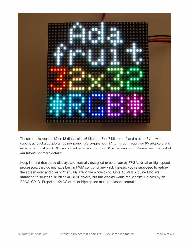
These panels require 12 or 13 digital pins (6 bit data, 6 or 7 bit control) and a good 5V powersupply, at least a couple amps per panel. We suggest our 2A (or larger) regulated 5V adapters andeither a terminal block DC jack, or solder a jack from our DC extension cord. Please read the rest ofour tutorial for more details!
Keep in mind that these displays are normally designed to be driven by FPGAs or other high speedprocessors; they do not have built in PWM control of any kind. Instead, you're supposed to redrawthe screen over and over to 'manually' PWM the whole thing. On a 16 MHz Arduino Uno, wemanaged to squeeze 12-bit color (4096 colors) but this display would really shine if driven by anFPGA, CPLD, Propeller, XMOS or other high speed multi-processor controller.
© Adafruit Industries https://learn.adafruit.com/32x16-32x32-rgb-led-matrix Page 4 of 43

Of course, we wouldn't leave you with a datasheet and a "good luck!" We have a full wiringdiagrams and working Arduino library code with examples from drawing pixels, lines, rectangles,circles and text. You'll get your color blasting within the hour! On an Arduino Uno or Mega, you'llneed 12 digital pins, and about 800 bytes of RAM to hold the 12-bit color image (double that for the32x32 matrix).
The library works ONLY with the Arduino Uno and Mega. Other boards (such as the ArduinoLeonardo) ARE NOT SUPPORTED.�
© Adafruit Industries https://learn.adafruit.com/32x16-32x32-rgb-led-matrix Page 5 of 43

PowerAlthough LEDs are very efficient light sources, get enough of them in one place and the currentreally adds up.
A single 32x16 or 32x32 RGB matrix, running full tilt (all pixels set white), can require nearly 4Amps of current! Double that figure for a 64x32 matrix.
On average though, displaying typical graphics and animation, these panels will use less…a 2Asupply is usually sufficient for a single 32x16 or 32x32 panel, or 4A for a 64x32 panel. There’s noharm in using a larger power supply rated for more Amps (e.g. a 10A supply), but never use onewith a higher Voltage (use 5V, period)!
On these panels, the power connection is separate from the data connection. Let’s begin byconnecting a 5V supply…
Our parts suppliers occasionally make revisions to designs. As a result, the connections havechanged over time. We'll walk through the different wiring combinations here…pick the explanationthat matches the panel(s) you received.
Two different types of power connectors have made an appearance:
On the left is a screw post power connector (with adjacent pads for soldering wires directly). On theright, a Molex-style header. Some panels will have two headers…the power cable included withthese panels has connectors for both headers.
With the posts-and-pads connector, you can either screw down the spades from the power cable, or
© Adafruit Industries https://learn.adafruit.com/32x16-32x32-rgb-led-matrix Page 6 of 43
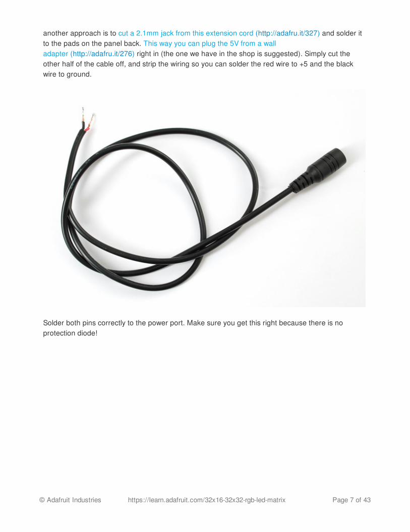
another approach is to cut a 2.1mm jack from this extension cord (http://adafru.it/327) and solder itto the pads on the panel back. This way you can plug the 5V from a walladapter (http://adafru.it/276) right in (the one we have in the shop is suggested). Simply cut theother half of the cable off, and strip the wiring so you can solder the red wire to +5 and the blackwire to ground.
Solder both pins correctly to the power port. Make sure you get this right because there is noprotection diode!
© Adafruit Industries https://learn.adafruit.com/32x16-32x32-rgb-led-matrix Page 7 of 43

If your panel has the Molex-style header, just plug in the included power cable, observing thecorrect polarity.
The spades at the opposite end of this power cable can be screwed into a 2.1mm terminal blockadapter. Works nicely! Don't allow the exposed connectors to contact metal though…you should
© Adafruit Industries https://learn.adafruit.com/32x16-32x32-rgb-led-matrix Page 8 of 43

probably cover this with heat-shrink tube or electrical tape.
© Adafruit Industries https://learn.adafruit.com/32x16-32x32-rgb-led-matrix Page 9 of 43
ConnectionsThese panels are normally designed for chaining (linking end-to-end into larger displays)…theoutput of one panel connects to the input of the next, down the line.
With the limited RAM in an Arduino, chaining is seldom practical. Still, it’s necessary todistinguish the input and output connections on the panel…it won’t respond if we’re connectedto the wrong socket.
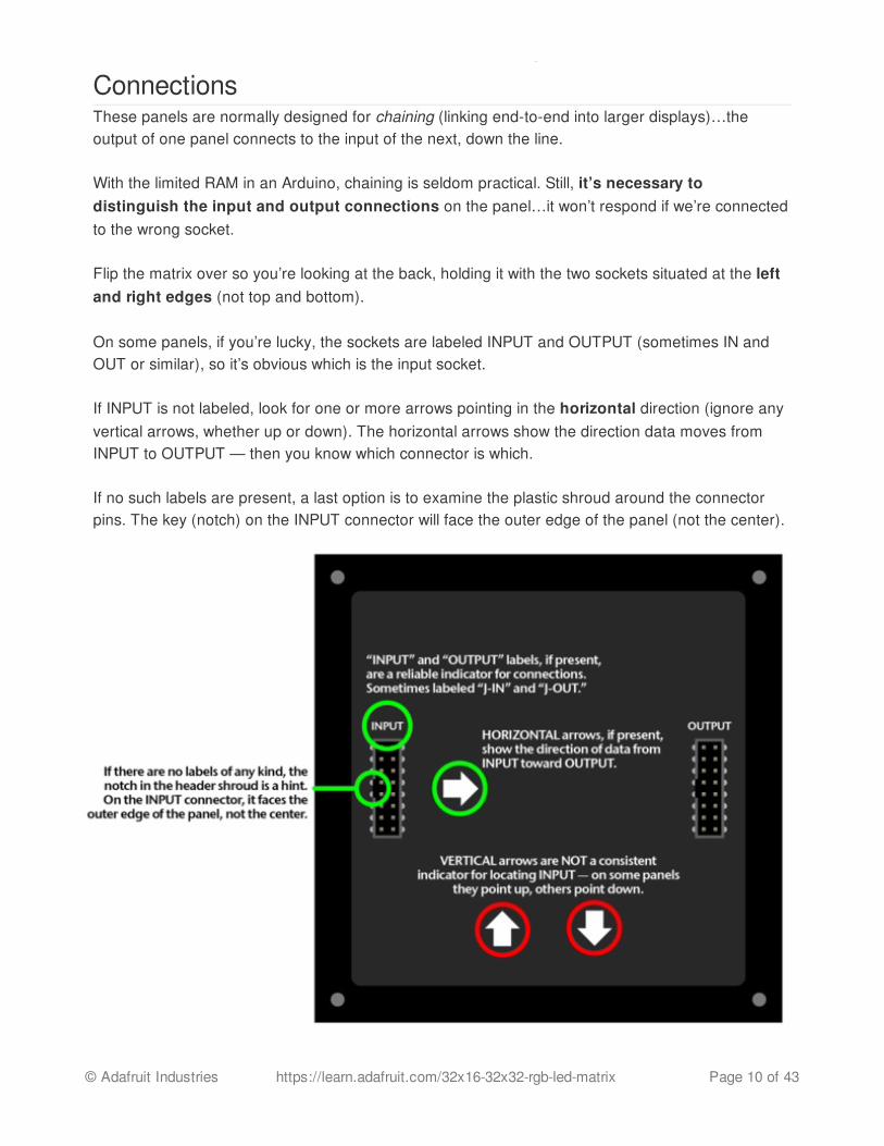
Flip the matrix over so you’re looking at the back, holding it with the two sockets situated at the leftand right edges (not top and bottom).
On some panels, if you’re lucky, the sockets are labeled INPUT and OUTPUT (sometimes IN andOUT or similar), so it’s obvious which is the input socket. If INPUT is not labeled, look for one or more arrows pointing in the horizontal direction (ignore anyvertical arrows, whether up or down). The horizontal arrows show the direction data moves fromINPUT to OUTPUT — then you know which connector is which. If no such labels are present, a last option is to examine the plastic shroud around the connectorpins. The key (notch) on the INPUT connector will face the outer edge of the panel (not the center).
© Adafruit Industries https://learn.adafruit.com/32x16-32x32-rgb-led-matrix Page 10 of 43
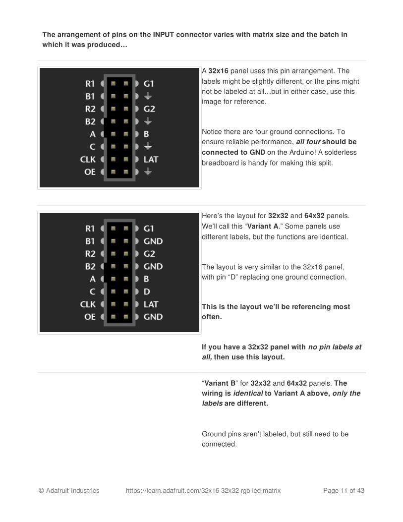
The arrangement of pins on the INPUT connector varies with matrix size and the batch inwhich it was produced…
A 32x16 panel uses this pin arrangement. Thelabels might be slightly different, or the pins mightnot be labeled at all…but in either case, use thisimage for reference.
Notice there are four ground connections. Toensure reliable performance, all four should beconnected to GND on the Arduino! A solderlessbreadboard is handy for making this split.
Here’s the layout for 32x32 and 64x32 panels.We’ll call this “Variant A.” Some panels usedifferent labels, but the functions are identical.
The layout is very similar to the 32x16 panel,with pin “D” replacing one ground connection.
This is the layout we’ll be referencing mostoften.
If you have a 32x32 panel with no pin labels atall, then use this layout.
“Variant B” for 32x32 and 64x32 panels. Thewiring is identical to Variant A above, only thelabels are different.
Ground pins aren’t labeled, but still need to beconnected.
© Adafruit Industries https://learn.adafruit.com/32x16-32x32-rgb-led-matrix Page 11 of 43

LAT (latch) is labeled STB (strobe) here.R1/G1/B1/R2/G2/B2 are changedto R0/G0/B0/R1/G1/B1…but again, no functionaldifference, it’s just ink.
Our earliest 32x32 panels had a two-socket design, let’s call it “Variant C.” All the samepin functions are present but the layout is verydifferent.
R/G/B on the upper socket correspond toR1/G1/B1 in Variant A. R/G/B on the lower socketcorrespond to R2/G2/B2.
All the other signals (A/B/C/D/CLK/LAT/OE) need tobe connected to both sockets — e.g. one pin onthe Arduino drives both CLK pins, and so forth.
Connecting to ArduinoThere are two methods for connecting a matrix to an Arduino:
1. Jumper wires inserted between Arduino headers and a ribbon cable — this works well fortesting and prototyping, but is not durable.
2. Building a proto shield — this is best for permanent installations.
These panels are normally run by very fast processors or FPGAs, not a 16 MHz Arduino. Toachieve reasonable performance in this limited environment, our software is optimizedby tying specific signals to specific Arduino pins. A few control lines can be reconfigured, butothers are very specific…you can’t wire the whole thing willy-nilly. The next two pagesdemonstrate compatible wiring…one using jumper wires, the other a proto shield…
© Adafruit Industries https://learn.adafruit.com/32x16-32x32-rgb-led-matrix Page 12 of 43

© Adafruit Industries https://learn.adafruit.com/32x16-32x32-rgb-led-matrix Page 13 of 43

Connecting with Jumper WiresRibbon cables and their corresponding headers are sometimes a topological puzzle. Here’s a trickto help keep track…
If you hold the ribbon cable flat — no folds — and with both connectors facing you, keys pointed thesame direction — now there is a 1:1 correlation between the pins. The top-right pin on one pluglinks to the top-right on the other plug, and so forth. This holds true even if the cable has a doubled-over strain relief. As long as the keys point the same way and the plugs face the same way,pins are in the same positions at both ends.
Plugged into a socket on the LED matrix, one header now faces away from you. If you double thecable back on itself (not a twist, but a fold)…to access a specific pin on the socket, the left and rightcolumns are now mirrored (rows are in the same order — the red stripe provides a point ofreference). You’re looking “up” into the plug rather than “down” into the socket.
For example, R1 (the top-left pin on the INPUT socket) appears at the top-right of the exposed plug.You can jam a wire jumper in that hole to a corresponding pin on the Arduino…
© Adafruit Industries https://learn.adafruit.com/32x16-32x32-rgb-led-matrix Page 14 of 43

So! From the prior page, refer to the socket that’scorrect for your matrix type. The labels may be alittle different (or none at all), but most are prettyclose to what’s shown here.
Then swap the columns to find the correct positionfor a given signal.
© Adafruit Industries https://learn.adafruit.com/32x16-32x32-rgb-led-matrix Page 15 of 43

Either end of the ribbon cable can be plugged into the matrix INPUT socket. Notice below, the“key” faces the same way regardless.
With the free end of the ribbon toward the center of the matrix, the Arduino can be hidden behind it.
With the free end of the ribbon off the side, it’s easier to see both the front of the matrix and theArduino simultaneously, for making additional connections or for troubleshooting.
Using color-coded wires helps a lot! If you don’t have colored wires, that’s okay, just pay closeattention where everything goes. Our goal is a fully-populated plug like this:
So! Let’s proceed with the wiring, in groups…
Connect Ground Wires
32x32 and 64x32 matrices require three groundconnections. 32x16 matrices have four.
© Adafruit Industries https://learn.adafruit.com/32x16-32x32-rgb-led-matrix Page 16 of 43

Current Arduino Uno boards have three groundpins (the third is next to pin 13). If you needadditional ground connections — for a 32x16matrix, or if using an older Arduino board with only2 ground pins — a solderless breadboard is handyfor linking all these pins.
Arduino Mega boards have five ground pins.Same three as the Arduino Uno, plus two morenext to pins 52 & 53.
© Adafruit Industries https://learn.adafruit.com/32x16-32x32-rgb-led-matrix Page 17 of 43

Upper RGB Data
Pins R1, G1 and B1 (labeled R0, B0 and G0 onsome matrices) deliver data to the top half of thedisplay.
On the Arduino Uno, connect these to digital pins2, 3 and 4.
On Arduino Mega, connect to pins 24, 25 and 26.
© Adafruit Industries https://learn.adafruit.com/32x16-32x32-rgb-led-matrix Page 18 of 43
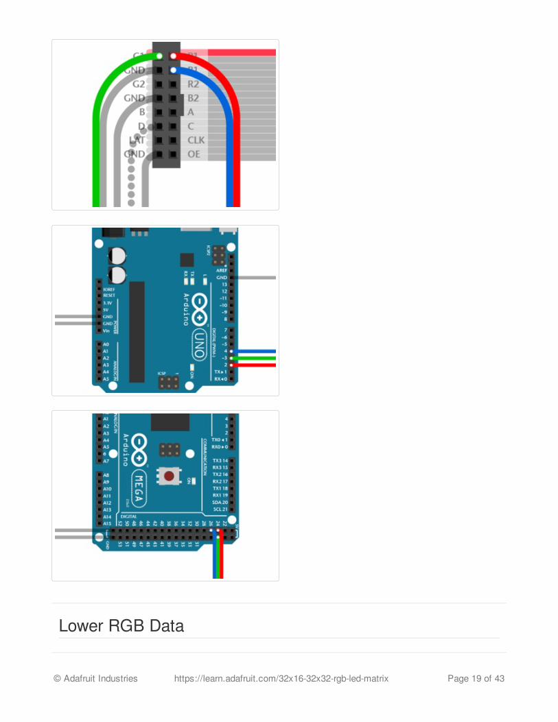
Lower RGB Data
© Adafruit Industries https://learn.adafruit.com/32x16-32x32-rgb-led-matrix Page 19 of 43
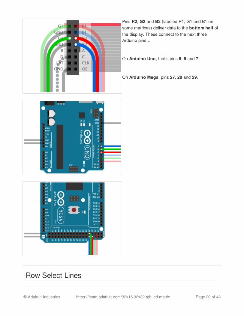
Pins R2, G2 and B2 (labeled R1, G1 and B1 onsome matrices) deliver data to the bottom half ofthe display. These connect to the next threeArduino pins…
On Arduino Uno, that’s pins 5, 6 and 7.
On Arduino Mega, pins 27, 28 and 29.
Row Select Lines
© Adafruit Industries https://learn.adafruit.com/32x16-32x32-rgb-led-matrix Page 20 of 43

Pins A, B, C and D select which two rows of thedisplay are currently lit. (32x16 matrices don’thave a “D” pin — it’s connected to groundinstead.)
These connect to pins A0, A1, A2 and (if D pinpresent) A3. This is the same for both the ArduinoUno and Mega.
LAT Wire
For 32x32 and 64x32 matrices, LAT connects toArduino pin 10.
For a 32x16 matrix, use Arduino pin A3.
This is the same for Arduino Uno or Mega.
The LAT (latch) signal marks the end of a row ofdata.
© Adafruit Industries https://learn.adafruit.com/32x16-32x32-rgb-led-matrix Page 21 of 43

CLK Wire
CLK connects to pin 8 on an Arduino Uno, or pin11 on an Arduino Mega.
The CLK (clock) signal marks the arrival of each bitof data.
© Adafruit Industries https://learn.adafruit.com/32x16-32x32-rgb-led-matrix Page 22 of 43

OE Wire
© Adafruit Industries https://learn.adafruit.com/32x16-32x32-rgb-led-matrix Page 23 of 43

Last one!
OE connects to Arduino pin 9. This is the same forboth the Arduino Uno and Mega.
OE (output enable) switches the LEDs off whentransitioning from one row to the next.
That’s it. You can skip ahead to the “Test Example Code” page now.
© Adafruit Industries https://learn.adafruit.com/32x16-32x32-rgb-led-matrix Page 24 of 43

Connecting Using a Proto ShieldAs mentioned on the “Jumper” page: if you hold a ribbon cable flat — no folds — and with bothconnectors facing you, keys pointed the same direction — there’s is a 1:1 correlation between thepins. The top-right pin on one plug links to the top-right on the other plug, and so forth. This holdstrue even if the cable has a doubled-over strain relief. As long as the keys point the same wayand the plugs face the same way, pins are in the same positions at both ends.
Either end of the ribbon cable can be plugged into the matrix INPUT socket.
The free end of the ribbon can point toward the center of the matrix, or hang off the side…thepinout is still the same. Notice below the direction of the “key” doesn’t change.
A dual-row header gets installed on the proto shield, similar to the connector on the matrix. Just likethe ribbon cable lying flat, as long as these two headers are aligned the same way, they’ll matchpin-for-pin; unlike the jumper wire method from the prior page, mirroring doesn’t happen.
© Adafruit Industries https://learn.adafruit.com/32x16-32x32-rgb-led-matrix Page 25 of 43

Wires are then soldered from the header to specific Arduino pins on the proto shield. Try to keepwire lengths reasonably short to avoid signal interference.
Using color-coded wires helps a lot! If you don’t have colored wires, that’s okay, just pay closeattention where everything goes. Our goal is a proto shield something like this:
© Adafruit Industries https://learn.adafruit.com/32x16-32x32-rgb-led-matrix Page 26 of 43
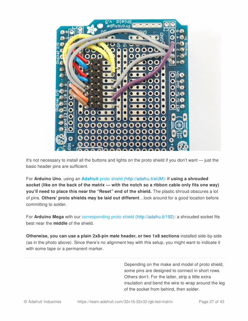
It’s not necessary to install all the buttons and lights on the proto shield if you don’t want — just thebasic header pins are sufficient.
For Arduino Uno, using an Adafruit proto shield (http://adafru.it/eUM): if using a shroudedsocket (like on the back of the matrix — with the notch so a ribbon cable only fits one way)you’ll need to place this near the “Reset” end of the shield. The plastic shroud obscures a lotof pins. Others’ proto shields may be laid out different…look around for a good location beforecommitting to solder.
For Arduino Mega with our corresponding proto shield (http://adafru.it/192): a shrouded socket fitsbest near the middle of the shield.
Otherwise, you can use a plain 2x8-pin male header, or two 1x8 sections installed side-by-side(as in the photo above). Since there’s no alignment key with this setup, you might want to indicate itwith some tape or a permanent marker.
Depending on the make and model of proto shield,some pins are designed to connect in short rows.Others don’t. For the latter, strip a little extrainsulation and bend the wire to wrap around the legof the socket from behind, then solder.
© Adafruit Industries https://learn.adafruit.com/32x16-32x32-rgb-led-matrix Page 27 of 43

Connect Ground Wires
32x32 and 64x32 matrices require three groundconnections. 32x16 matrices have four.
Most proto shields have tons of grounding points,so you shouldn’t have trouble finding places toconnect these.
Upper RGB Data
Pins R1, G1 and B1 (labeled R0, B0 and G0 onsome matrices) deliver data to the top half of thedisplay.
On the Arduino Uno, connect these to digital pins2, 3 and 4.
© Adafruit Industries https://learn.adafruit.com/32x16-32x32-rgb-led-matrix Page 28 of 43

On Arduino Mega, connect to pins 24, 25 and 26.
Lower RGB Data
Pins R2, G2 and B2 (labeled R1, G1 and B1 onsome matrices) deliver data to the bottom half ofthe display. These connect to the next threeArduino pins…
On Arduino Uno, that’s pins 5, 6 and 7.
On Arduino Mega, pins 27, 28 and 29.
Row Select Lines
Pins A, B, C and D select which two rows of thedisplay are currently lit. (32x16 matrices don’thave a “D” pin — it’s connected toground instead.)
These connect to pins A0, A1, A2 and (if D pinpresent) A3. This is the same for both the Arduino
© Adafruit Industries https://learn.adafruit.com/32x16-32x32-rgb-led-matrix Page 29 of 43

Uno and Mega.
LAT Wire
For 32x32 and 64x32 matrices, LAT connects toArduino pin 10.
For a 32x16 matrix, use Arduino pin A3.
This is the same for Arduino Uno or Mega.
The LAT (latch) signal marks the end of a row ofdata.
CLK Wire
CLK connects to pin 8 on an Arduino Uno, or pin11 on an Arduino Mega.
The CLK (clock) signal marks the arrival of each bitof data.
© Adafruit Industries https://learn.adafruit.com/32x16-32x32-rgb-led-matrix Page 30 of 43

OE WireLast one!
OE connects to Arduino pin 9. This is the same forboth the Arduino Uno and Mega.
OE (output enable) switches the LEDs off whentransitioning from one row to the next.
Here’s that photo again of a completed shield. You can tell this is for a 32x16 matrix, because thereare four ground connections (one of the long vertical strips is a ground bus — see the tiny jumpersthere?).
The ribbon cable to the matrix would plug into this with the key facing left.
The colors don’t quite match the examples above, but are close. G1 and G2 are yellow wires. LAT isthe purple wire.
© Adafruit Industries https://learn.adafruit.com/32x16-32x32-rgb-led-matrix Page 31 of 43

© Adafruit Industries https://learn.adafruit.com/32x16-32x32-rgb-led-matrix Page 32 of 43

Test Example CodeWe have example code ready to go for these displays. It's compatible with the Arduino Uno orMega…but not other boards like the Leonardo, nor “Arduino-like” boards such as Netduino…programming gurus might be able to port it to other microcontrollers by adapting the C++ source,but as written it does some pretty low-level, non-portable things.
Two libraries need to be downloaded and installed: first is the RGB Matrix Panellibrary (http://adafru.it/aHj) (this contains the low-level code specific to this device), and second isthe Adafruit GFX Library (http://adafru.it/aJa) (which handles graphics operations common to manydisplays we carry). Download both ZIP files, uncompress and rename the folders to'RGBmatrixPanel' and 'Adafruit_GFX' respectively, place them inside your Arduino libraries folderand restart the Arduino IDE. If this is all unfamiliar, we have a tutorial introducing Arduino libraryconcepts and installation (http://adafru.it/aYG).
Now you are ready to test! Open up the IDE and loadFile®®Examples®®RGBmatrixPanel®® testcolors_16x32 (for the 16x32 panel) orFile®®Examples®®RGBmatrixPanel®®colorwheel_32x32 (for the 32x32 panel).
If you are using the 32x32 panel, before you upload this code to the Arduino, edit the pin definitionsto match the specific wiring used by your panel (single- or double-header interface). Comments inthe file will direct you to what needs changed (if anything).
If using an Arduino Mega 2560, in addition to wiring changes previously mentioned, you'll need tomake a small change to each of the example sketches. This line:
Should be changed to:
(Any of digital pins 10-13 and 50-53 can be used for this function on the Mega, with thecorresponding wiring change. The examples all reference pin 11, as pin 10 may be in use for the32x32 panel.)
After uploading, with the 16x32 panel you should see the following:
The library works ONLY with the Arduino Uno and Mega. Other boards (such as the ArduinoLeonardo) ARE NOT SUPPORTED.�
#define CLK 8 // MUST be on PORTB! (Use pin 11 on Mega)
#define CLK 11
© Adafruit Industries https://learn.adafruit.com/32x16-32x32-rgb-led-matrix Page 33 of 43

This is a test pattern that shows 512 colors (out of 4096) on the 512 pixels. Since there's no reallyelegant way to show a 3-dimensional color space (R/G/B) in two dimensions, there's just repeatinggrids of red/green with increasing blue. Anyways, this shows you the range of colors you canachieve!
or, with the 32x32 panel:
© Adafruit Industries https://learn.adafruit.com/32x16-32x32-rgb-led-matrix Page 34 of 43

Now that you've got it working here are a few things to look for:
The most useful line to look at is:
which is where we actually draw to the display. This code only draws one pixel at a time. The x andy coordinates are the individual pixels of the display. (0,0) is in the top left corner, (31, 15) is in thebottom right (remember that we start counting at 0 here!). To create a color, you will want to use thehelper funciton Color333 which will take three 3-bit numbers and combine them into a singlepacked integer. So for example, the first argument, r can range from 0 to 7. Likewise for gand b. Tomake a pixel that is pure red, r would be 7 and g, b would be 0. To make a white pixel, set all to 7.To make a black (off) pixel, set the colors to 0. A similar function, Color444, accepts three 4-bitnumbers for up to 4096 colors.
Now we can open up the next example, which shows the rest of the library capabilities.
matrix.drawPixel(x, y, matrix.Color333(r, g, b));
© Adafruit Industries https://learn.adafruit.com/32x16-32x32-rgb-led-matrix Page 35 of 43

© Adafruit Industries https://learn.adafruit.com/32x16-32x32-rgb-led-matrix Page 36 of 43
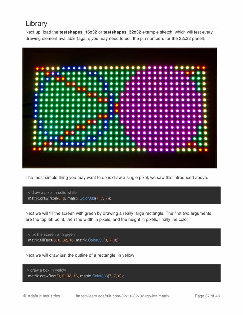
LibraryNext up, load the testshapes_16x32 or testshapes_32x32 example sketch, which will test everydrawing element available (again, you may need to edit the pin numbers for the 32x32 panel).
The most simple thing you may want to do is draw a single pixel, we saw this introduced above.
Next we will fill the screen with green by drawing a really large rectangle. The first two argumentsare the top left point, then the width in pixels, and the height in pixels, finally the color
Next we will draw just the outline of a rectangle, in yellow
// draw a pixel in solid white matrix.drawPixel(0, 0, matrix.Color333(7, 7, 7));
// fix the screen with green matrix.fillRect(0, 0, 32, 16, matrix.Color333(0, 7, 0));
// draw a box in yellow matrix.drawRect(0, 0, 32, 16, matrix.Color333(7, 7, 0));
© Adafruit Industries https://learn.adafruit.com/32x16-32x32-rgb-led-matrix Page 37 of 43

Next you may want to draw lines. The drawLine procedure will draw a line in any color you want,we used this to draw a big X
The next shapes we draw are circles. You can draw the outline of a circle with drawCircle or fill acircle with fillCircle. The first two arguments are the center point, the third argument is the radius inpixels, finally the color to use.
fill allows you to fill the entire screen with a single color
Finally, we draw the text that is shown up top as the demonstration image. We can use the printfunction, which you'll be familiar with from Serial. You can use print to print strings, numbers,variables, etc. However, we need to set up the printing before just going off and doing it! First, wemust set the cursor location with setCursor which is where the top left pixel of the first character willgo, this can be anywhere but note that text characters are 8 pixels high by default. NextsetTextSize lets you set the size to 1 (8 pixel high) or 2 (16 pixel high for really big text!), youprobably want just to stick with 1 for now. Lastly we can set the color of the text with setTextColor.Once this is all done, we can just useprint('1') to print the character "1".
// draw an 'X' in red matrix.drawLine(0, 0, 31, 15, matrix.Color333(7, 0, 0)); matrix.drawLine(31, 0, 0, 15, matrix.Color333(7, 0, 0));
// draw a blue circle matrix.drawCircle(7, 7, 7, matrix.Color333(0, 0, 7)); // fill a violet circle matrix.fillCircle(23, 7, 7, matrix.Color333(7, 0, 7));
// fill the screen with 'black' matrix.fill(matrix.Color333(0, 0, 0));
© Adafruit Industries https://learn.adafruit.com/32x16-32x32-rgb-led-matrix Page 38 of 43

// draw some text! matrix.setCursor(1, 0); // start at top left, with one pixel of spacing matrix.setTextSize(1); // size 1 == 8 pixels high // print each letter with a rainbow color matrix.setTextColor(matrix.Color333(7,0,0)); matrix.print('1'); matrix.setTextColor(matrix.Color333(7,4,0)); matrix.print('6'); matrix.setTextColor(matrix.Color333(7,7,0)); matrix.print('x'); matrix.setTextColor(matrix.Color333(4,7,0)); matrix.print('3'); matrix.setTextColor(matrix.Color333(0,7,0)); matrix.print('2'); matrix.setCursor(1, 9); // next line matrix.setTextColor(matrix.Color333(0,7,7)); matrix.print('*'); matrix.setTextColor(matrix.Color333(0,4,7)); matrix.print('R'); matrix.setTextColor(matrix.Color333(0,0,7)); matrix.print('G'); matrix.setTextColor(matrix.Color333(4,0,7)); matrix.print("B"); matrix.setTextColor(matrix.Color333(7,0,4)); matrix.print("*");
© Adafruit Industries https://learn.adafruit.com/32x16-32x32-rgb-led-matrix Page 39 of 43

© Adafruit Industries https://learn.adafruit.com/32x16-32x32-rgb-led-matrix Page 40 of 43

How the Matrix WorksThere's zero documention out there on how these matrices work, and no public datasheets or specsheets so we are going to try to document how they work.
First thing to notice is that there are 512 RGB LEDs in a 16x32 matrix. Like pretty much every matrixout there, you can't drive all 512 at once. One reason is that would require a lot of current,another reason is that it would be really expensive to have so many pins. Instead, the matrix isdivided into 8 interleaved sections/strips. The first section is the 1st 'line' and the 9th 'line' (32 x 2RGB LEDs = 64 RGB LEDs), the second is the 2nd and 10th line, etc until the last section which isthe 7th and 16th line. You might be asking, why are the lines paired this way? wouldnt it be nicer tohave the first section be the 1st and 2nd line, then 3rd and 4th, until the 15th and 16th? The reasonthey do it this way is so that the lines are interleaved and look better when refreshed, otherwisewe'd see the stripes more clearly.
So, on the PCB is 12 LED driver chips. These are like 74HC595s but they have 16 outputs and theyare constant current. 16 outputs * 12 chips = 192 LEDs that can be controlled at once, and 64 * 3 (RG and B) = 192. So now the design comes together: You have 192 outputs that can control one lineat a time, with each of 192 R, G and B LEDs either on or off. The controller (say an FPGA ormicrocontroller) selects which section to currently draw (using A, B, and C address pins - 3 bits canhave 8 values). Once the address is set, the controller clocks out 192 bits of data (24 bytes) andlatches it. Then it increments the address and clocks out another 192 bits, etc until it gets to address#7, then it sets the address back to #0
The only downside of this technique is that despite being very simple and fast, it has no PWMcontrol built in! The controller can only set the LEDs on or off. So what do you do when you wantfull color? You actually need to draw the entire matrix over and over again at very high speeds toPWM the matrix manually. For that reason, you need to have a very fast controller (50 MHz is aminimum) if you want to do a lot of colors and motion video and have it look good.
How quickly can we feed data to the matrix? Forum users Andrew Silverman and Ryan Brown havebeen posting their progress (http://adafru.it/aO2) driving the 16x32 matrix with an FPGA, and thelimit appears to be somewhere between 40 and 50 MHz. Ryan writes: “I haven't validated 100%pixel correctness, but 50 MHz seems to work for me […] 67MHz definitely did not work.” He alsoprovided this graph showing current draw relative to clock frequency:
© Adafruit Industries https://learn.adafruit.com/32x16-32x32-rgb-led-matrix Page 41 of 43
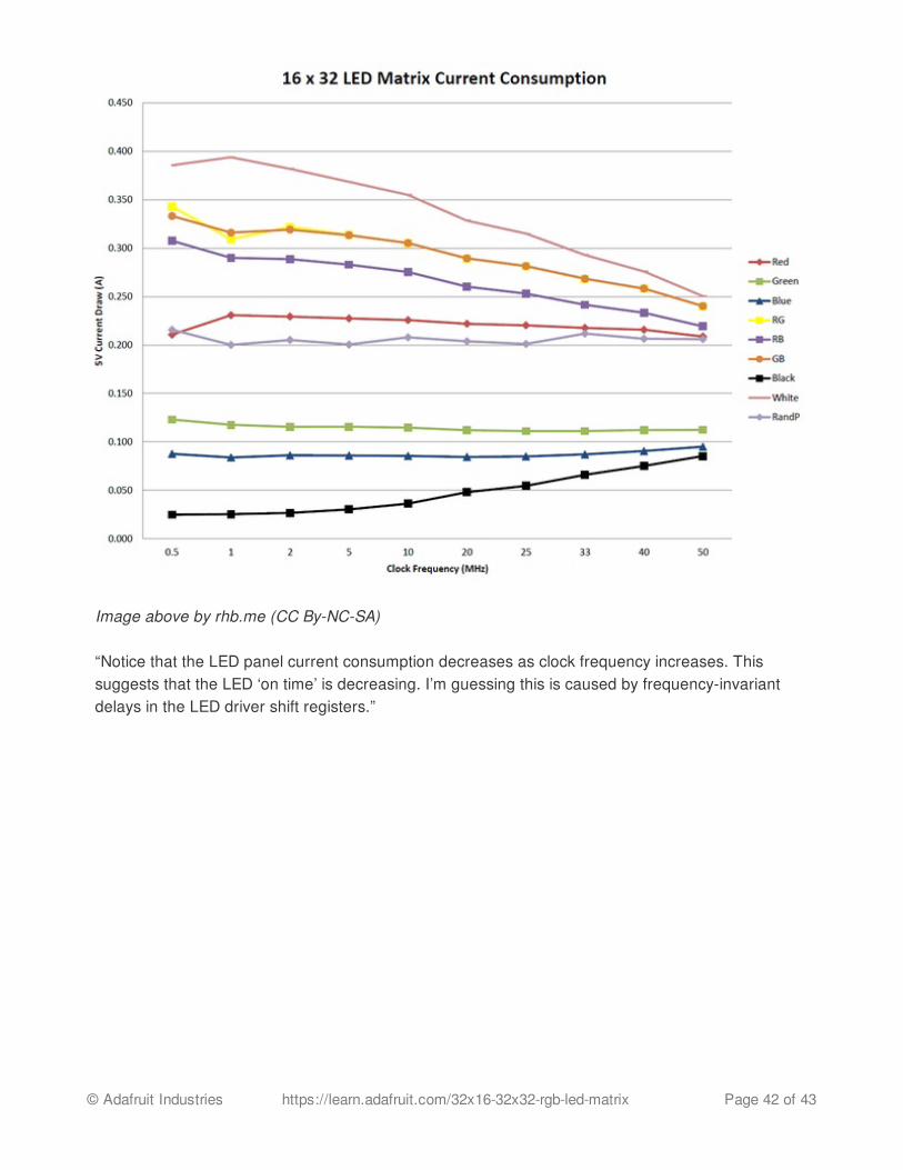
Image above by rhb.me (CC By-NC-SA)
“Notice that the LED panel current consumption decreases as clock frequency increases. Thissuggests that the LED ‘on time’ is decreasing. I’m guessing this is caused by frequency-invariantdelays in the LED driver shift registers.”
© Adafruit Industries https://learn.adafruit.com/32x16-32x32-rgb-led-matrix Page 42 of 43

DownloadsDownload our RGBmatrixPanel library (http://adafru.it/aHj) by clicking the ZIP button near the topleft corner, rename the uncompressed folder RGBmatrixPanel. Check that the RGBmatrixPanelfolder contains RGBmatrixPanel.cpp andRGBmatrixPanel.h. Similarly, download theAdafruit_GFX library here (http://adafru.it/aJa) . Rename the uncompressed folder Adafruit_GFXand confirm it contains Adafruit_GFX.cpp and Adafruit_GFX.h. Place both library folders insideyour<arduinosketchfolder>/libraries/ folder. You may need to create the libraries subfolder if itsyour first library. Restart the IDE.
© Adafruit Industries Last Updated: 2015-05-04 08:40:08 PM EDT Page 43 of 43