320D-DL en - Heavy machinery and equipment …37e)… · 320D/320D L Hydraulic Excavators ......
25
320D/320D L Hydraulic Excavators Engine Weights Engine Model Cat ® C6.6 ACERT™ Operating Weight – Std. Undercarriage 20 660 kg-21 310 kg Gross Power – SAE J1995 111 kW Operating Weight – Long Undercarriage 21 830 kg-21 900 kg Net Power – SAE J1349/ISO 9249 103 kW
Transcript of 320D-DL en - Heavy machinery and equipment …37e)… · 320D/320D L Hydraulic Excavators ......

320D/320D LHydraulic Excavators
Engine Weights
Engine Model Cat® C6.6 ACERT™ Operating Weight – Std. Undercarriage 20 660 kg-21 310 kg
Gross Power – SAE J1995 111 kW Operating Weight – Long Undercarriage 21 830 kg-21 900 kg
Net Power – SAE J1349/ISO 9249 103 kW
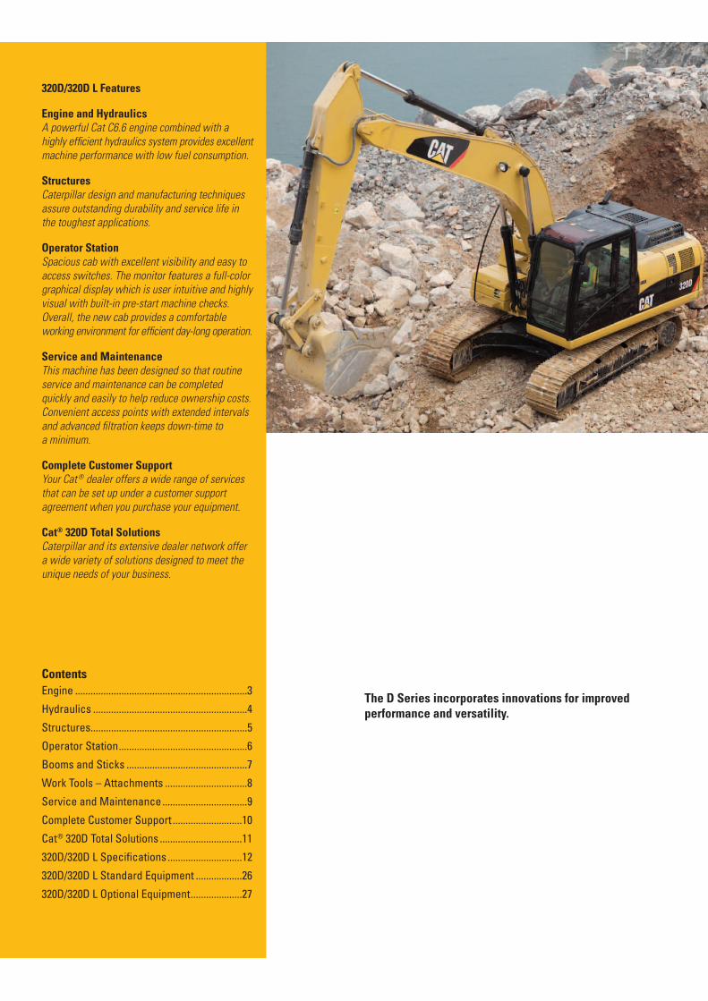
320D/320D L Features
Engine and HydraulicsA powerful Cat C6.6 engine combined with a
highly ef�cient hydraulics system provides excellent
machine performance with low fuel consumption.
StructuresCaterpillar design and manufacturing techniques
assure outstanding durability and service life in
the toughest applications.
Operator StationSpacious cab with excellent visibility and easy to
access switches. The monitor features a full-color
graphical display which is user intuitive and highly
visual with built-in pre-start machine checks.
Overall, the new cab provides a comfortable
working environment for ef�cient day-long operation.
Service and MaintenanceThis machine has been designed so that routine
service and maintenance can be completed
quickly and easily to help reduce ownership costs.
Convenient access points with extended intervals
and advanced � ltration keeps down-time to
a minimum.
Complete Customer SupportYour Cat ® dealer offers a wide range of services
that can be set up under a customer support
agreement when you purchase your equipment.
Cat® 320D Total SolutionsCaterpillar and its extensive dealer network offer
a wide variety of solutions designed to meet the
unique needs of your business.
Contents
Engine ...................................................................3
Hydraulics ............................................................4
Structures.............................................................5
Operator Station..................................................6
Booms and Sticks ...............................................7
Work Tools – Attachments ................................8
Service and Maintenance.................................9
Complete Customer Support ...........................10
Cat® 320D Total Solutions ................................11
320D/320D L Speci$cations .............................12
320D/320D L Standard Equipment ..................26
320D/320D L Optional Equipment....................27
The D Series incorporates innovations for improvedperformance and versatility.

EngineClean, quiet operation and superior power with ACERT™ Technology.
Cat C6.6
The 320D is equipped with a Cat C6.6 ACERT™ engine
which is powerful, strong and durable meeting all of your
application needs. An ECO-mode feature helps to reduce
fuel consumption by up to 15% for fuel conscious customers.
ACERT engines incorporate proven, robust components and
precision manufacturing you can count on for reliable and
efficient day-long operation.
Automatic Engine Speed Control
Automatic Engine Control is activated during no-load or
light-load conditions and reduces engine speed to minimize
fuel consumption.
Air Cleaner
The radial seal air filter features a double-layered filter core
for more efficient filtration and is located in a compartment
behind the cab. A warning is displayed on the monitor when
dust accumulates above a preset level.
Filtration System
The C6.6 engine features an improved filtration system
ensuring good reliability to fuel injection system components.
Low Sound, Low Vibration
The Cat C6.6 improves operator comfort by reducing
sound and vibration.
3

HydraulicsHigh efficiency and performance with low effort and precise control.
Hydraulic System
Hydraulic system pressure is 35 000 kPa, with 205 L/min
flow from each of the two hydraulic pumps for increased
digging performance and productivity.
Pilot System
The pilot pump is independent from the main pumps and
controls the front linkage, swing and travel operations.
Component Layout
The 320D hydraulic system and component locations have
been designed to provide a high level of system efficiency.
The main pumps, control valves and hydraulic tank are
located close together to allow for shorter tubes and lines
between components, which reduce friction loss, and
pressure drops.
Hydraulic Cross Sensing System
The hydraulic cross sensing system utilizes each of two
hydraulic pumps to 100 percent of engine power, under all
operating conditions. This improves productivity with faster
implement speeds and quicker, stronger pivot turns.
Auxiliary Hydraulic Valve
Control Circuits are available as attachments which improves
versatility. They allow operation of high and medium pressure
tools such as shears, grapples, hammers, pulverizers, multi-
processors and vibratory plate compactors.
Boom and Stick Regeneration Circuit
Boom and stick regeneration circuits save energy during
boom-down and stick-in operations which increases efficiency,
reduces cycle times and pressure loss for higher productivity,
lower operating costs and increased fuel efficiency.
Hydraulic Cylinder Snubbers
Snubbers are located at the rod-end of the boom cylinders
and both ends of the stick cylinders to cushion shocks while
reducing sound levels and extending component life.
Hydraulic Activation Control Lever
For added safety, this lever must be in the operate position
to activate all machine hydraulic control functions.
Climate Control
Positive filtered ventilation with a pressurized cab is
standard. Fresh air or re-circulated air can be selected
with a switch on the left console.
4

StructuresCat® excavators are designed to handle the most rugged operating
conditions while providing long life and value.
Carbody Design and Track Roller Frames
X-shaped, box-section carbody provides excellent resistance to torsional bending. Robot-welded track
roller frames are press-formed, pentagonal units to deliver exceptional strength and service life.
Main Frame
Rugged main frame is designed for maximum durability and efficient use of materials.
Undercarriage
Durable Cat undercarriage absorbs stresses and provides excellent stability.
Rollers and Idlers
Sealed and lubricated track rollers, carrier rollers, and idlers provide excellent service life, to keep
the machine in the field longer.
Standard Undercarriage
The standard undercarriage is well suited for applications that require frequent repositioning
of the machine, have restricted working space or uneven, rocky terrain.
Long Undercarriage
The long (L) undercarriage maximizes stability and lift capacity. This long, wide, and sturdy
undercarriage offers a very stable work platform.
5

Operator StationDesigned for comfort, simple and easy operation, the 320D allows the
operator to focus on production.
Operator Station
The ergonomically designed operator station is spacious,
quiet and comfortable, assuring high productivity during
a long work day. All switches are located on the right-hand
console for convenient access.
Monitor
The monitor is a full color 400×234 pixels Liquid Crystal
Display (LCD) graphic display. The monitor angle can be
adjusted to minimize sun glare and has the capability of
displaying information in Chinese and twenty-six other
languages.
Joystick Control
Low effort, pilot operated joystick controls are designed
to match the operator’s natural wrist and arm position
for maximum comfort and minimum fatigue.
Seat
The standard suspension seat provides a variety of adjustments
to suit the operator’s size and weight including fore/aft, height
and weight. Wide adjustable armrests and a retractable seat
belt are also included.
Console
The consoles feature a simple, functional design to reduce
operator fatigue, ease of switch operation and excellent
visibility. Both consoles have attached armrests with
height adjustments.
Cab Exterior
The cab shell features thick steel tubing along the bottom
perimeter of the cab, improving resistance to fatigue and
vibration.
Cab Mounts
The cab shell is attached to the frame with viscous rubber
cab mounts, which dampen vibrations and sound levels while
enhancing operator comfort.
Windows
To maximize visibility, all glass is affixed directly to the cab,
eliminating window frames. The upper front windshield
opens, closes and stores on the roof above the operator
with a one-touch action release system.
Wipers
Pillar-mounted wipers increase the operator’s viewing area
and offer continuous and intermittent modes.

Booms and SticksDesigned-in flexibility to help bring higher production
and efficiency to all jobs.
Booms, Sticks and Attachments
Cat front linkages are designed for maximum flexibility, productivity and high efficiency what ever
the application.
Heavy Duty Reach Boom
The heavy duty reach boom features an optimum design that maximizes digging envelopes with two stick
choices, it also incorporates a large cross-section and internal baffle plates for long life and durability.
R2.5B1 and R2.9B1 stick options are also heavy duty and are made of high tensile strength steel using
a large box section design with interior baffle plates and an additional bottom guard.
Super Long Reach Front
This super long reach front option provides up to 15.2 m of reach and is designed for light duty
applications requiring an extra large working envelope.
7

Work Tools – AttachmentsThe 320D has an extensive selection of work tools to optimize
machine performance.
Cat Buckets and Cat Ground Engaging Tools (GET) are designed and matched to the machine ensuring
optimal performance and fuel consumption. They are built to Caterpillar specifications guaranteeing
quality and durability, whatever the application.
General Duty Buckets
General Duty buckets have been designed for machines digging in low-impact, moderately abrasive
materials such as dirt, loam, gravel and clay.
Heavy-Duty Buckets
Heavy-duty (HD) buckets are used for a wide range of moderately abrasive applications such as mixed
dirt, clay and rock. HD buckets have the best loading and dumping characteristics and will empty easier
in cohesive material. These feature a more robust construction than GP buckets.
Severe Duty Buckets
Severe duty are best suited to highly abrasive applications such as shot rock and granite.
Tool Control System
The optional tool control system maximizes work tool productivity by configuring hydraulic flow,
pressure, and operator controls to match a specific work tool. System versatility enables a wide range
of tools to be used.
Cat Hammers
Cat B Series Breakers feature high performance and reliability and have been specifically designed
to meet the differing needs of Chinese customers. They are the ideal choice for demolition, quarry,
mining, general construction and many other applications.
8

320D/320D L Specifications
Engine Swing Mechanism Sound Performance
Engine Model Cat® C6.6 ACERT™ Swing Speed 11.5 rpm Performance
Gross Power – 111 kW
SAE J1995
Net Power – 103 kW
SAE J1349/ISO 9249
Bore 105 mm
Stroke 127 mm
Displacement 6.6 L
• The Cat C6.6 meets exhaust emissions
equivalent to China Tier 2 engine emissions
and Stage 1 sound regulation.
• Net power advertised is the power available
at the #ywheel when the engine is equipped
with fan, air cleaner, muf#er and alternator.
• No engine derating needed up to 3000 m.
Weights
Operating Weight – 20 660 kg-21 310 kg
Std. Undercarriage
• Reach Boom (HD), R2.9 Stick (HD),
790 mm Track Shoes and 1.0 m3 Bucket
Operating Weight – 21 830 kg-21 900 kg
Long Undercarriage
• Reach Boom (HD), R2.9 Stick (HD),
790 mm Track Shoes and 1.0 m3 Bucket
Swing Torque 62 kN·m • When properly installed and maintained,
the cab offered by Caterpillar, when tested
Drive with doors and windows closed according to
China sound regulation Stage 1 requirementsMaximum 206 kN for operator sound exposure limits in effectDrawbar Pull at time of manufacture.Maximum 5.6 km/L • Hearing protection may be needed whenTravel Speed operating with an open operator station
and cab (when not properly maintained or
Hydraulic System doors/windows open) for extended periods
or in noisy environment.Main Implement 205 L/min
System – Maximum StandardsFlow (2x)
Maximum 35 000 kPa Brakes ISO 10265 2008
Pressure –
Equipment
Maximum 35 000 kPa
Pressure – Travel
Maximum 25 000 kPa
Pressure – Swing
Pilot System – 32.4 L/min
Maximum Flow
Pilot System – 3900 kPa
Maximum Pressure
Boom Cylinder – 120 mm
Bore
Operating Weight – 20 160 kg Boom Cylinder – 1260 mm320D GC Stroke
• Reach Boom, R2.9 Stick, 600 mm Track Stick Cylinder – 140 mmShoes and 0.9 m3 Bucket Bore
Stick Cylinder – 1504 mmService Refill Capacities Stroke
Fuel Tank Capacity 410 L B1 Family Bucket 120 mm
Cooling System 29 LCylinder – Bore
Engine Oil
Swing Drive
22 L
8 L
B1 Family Bucket
Cylinder – Stroke
1104 mm
Final Drive (each) 8 L
Hydraulic System 260 L
(including tank)
Hydraulic Tank 120 L
12

DimensionsAll dimensions are approximate.
1
6
3 2
54
Boom Options 320D 320D 320D 320D L 320D LReach Boom Reach Boom Reach Boom Reach Boom Reach Boom
(HD) (HD) (HD) (HD) (HD)
Stick R2.9 R2.9 R2.5 R2.9 R2.5(HD) (HD) (HD) (HD) (HD)
Bucket 1.0 m3 1.0 m3 1.0 m3 1.0 m3 1.0 m3
Shoe 600 mm 790 mm 600 mm 790 mm 790 mm
Undercarriage STD STD STD LC LC
Approximate Weight 20 730 kg 21 310 kg 20 660 kg 21 900 kg 21 830 kg
1 Overall Length 9460 mm 9460 mm 9460 mm 9460 mm 9460 mm
2 Overall Height 3030 mm 3030 mm 3050 mm 3030 mm 3030 mm
3 Height of Cab 2950 mm 2950 mm 2950 mm 2950 mm 2950 mm
4 Overall Width 2800 mm 2970 mm 2800 mm 3170 mm 3170 mm
5 Track Shoe Width 600 mm 790 mm 600 mm 790 mm 790 mm
6 Width of Upper Structure 2740 mm 2740 mm 2740 mm 2740 mm 2740 mm
13

320D/320D L Specifications
Working RangesAll dimensions are approximate.
�
�
3
4
� �
� �
� �
2
51
�
�
Boom Options Reach Boom Reach Boom5.7 m 5.7 m(HD) (HD)
Stick 2.9 m 2.5 m(HD) (HD)
Bucket 1.0 m3 1.0 m3
1 Maximum Digging Depth 6720 mm 6300 mm
2 Maximum Reach at Ground Level 10 020 mm 9630 mm
3 Maximum Cutting Height 9490 mm 9290 mm
4 Maximum Loading Height 6490 mm 6290 mm
5 Maximum Digging (Vertical Wall) 6060 mm 5650 mm
14

DimensionsAll dimensions are approximate.
1
34
5
Boom Options
Stick
Bucket
Shoe
Approximate Weight
1 Overall Length
2 Overall Height
3 Track Shoe Width
4 Overall Width
5 Length of Track
320D LSuper Long Reach Boom
8.85 m
6.28 m
0.45 m3
790 mm TG
22 649 kg
12 680 mm
3190 mm
790 mm
2980 mm
4455 mm
15
2

320D/320D L Specifications
Working RangesAll dimensions are approximate.
�
�
3
4
�
�� 5 �
� �
� �
2
16
�
�
Super Long Reach Working Ranges
Boom Options Super Long Reach Boom8.85 m
Stick Options 6.28 m
Bucket Options Excavation Ditch Cleaning
0.45 m3 0.60 m3
1 Maximum Digging Depth 11 880 mm 11 750 mm
2 Maximum Reach at Ground Level 15 720 mm 15 590 mm
3 Maximum Cutting Height 13 290 mm 13 230 mm
4 Maximum Loading Height 11 010 mm 11 140 mm
5 Minimum Loading Height 1970 mm 2090 mm
6 Maximum Vertical Wall Digging Depth 10 700 mm 11 310 mm
Bucket Digging Force (ISO) 60 kN 60 kN
Stick Digging Force (ISO) 46 kN 46 kN
16

Major Component Weights
Base machine with counterweight (without front linkage)
Standard Undercarriage with 600 mm triple grouser shoes 16 660 kg
Standard Undercarriage with 790 mm triple grouser shoes 17 250 kg
Long Undercarriage with 600 mm triple grouser shoes 17 250 kg
Long Undercarriage with 790 mm triple grouser shoes 17 840 kg
Upper Structure without counterweight 6230 kg
Counterweight 3710 kg
Boom
Two Boom Cylinders (each) 175 kg
Boom 5.7 m Heavy Duty Reach (includes lines, pins, and stick cylinder) 2020 kg
Stick Cylinder 280 kg
Stick
Stick R2.9B1 Heavy Duty (includes lines, pins, bucket cylinder and linkage) 1120 kg
Stick R2.5B1 Heavy Duty (includes lines, pins, bucket cylinder and linkage) 1090 kg
Bucket Cylinder 160 kg
Bucket Linkage 140 kg
320D Bucket Specifications
Capacity Width Tip Radius Weight Teeth Heavy Duty Reach Boom(with tips) Stick
m3 mm mm kg Qty R2.9 HD R2.5 HD
B1 Buckets
General Duty 1.0 1232 1559 828 6 f f
1.14 1360 1559 902 6 f f
Heavy Duty 1.0 1080 1556 886 5 * f
1.2 1232 1556 967 6 — *
Severe Duty (SD) 1.0 1080 1556 971 5 * f
320D L Bucket Specifications
Capacity Width Tip Radius Weight Teeth Heavy Duty Reach Boom(with tips) Stick
m3 mm mm kg Qty R2.9 HD R2.5 HD
B1 Buckets
General Duty 1.0 1232 1559 828 6 f f
Heavy Duty 1.0 1080 1556 886 5 f f
1.2 1232 1556 967 6 — f
Severe Duty (SD) 1.0 1080 1556 971 5 f f
Assumptions for maximum material density rating: f 1800 kg/m3 max material density
1. Front linkage fully extended at ground line * 1500 kg/m3 max material density
2. Bucket curled — Not Available
3. 100% bucket fill factor
17

320D/320D L Specifications
320D/320D L Work Tool Matching Guide
Boom Options Reach Boom
5.7 m
Stick Options R2.9B1 R2.5B1
Vibratory Plate Compactor CVP110 CVP110
Trash Grapple 2.7 m3 2.7 m3
Contractors’ Grapple yes yes
Hydraulic Thumb yes yes
Dedicated Quick Coupler yes yes
Machine Weight
Lower Structure 6650 7830
Upper Structure 10 010 10 010
Boom 1740 1740
Stick 820 820
Bucket 990 990
Cylinder 780 780
Linkage 130 130
Total 21 100 22 300
Buckets
SAE Capacity Weight of Width of Track Shoe MachineModel of Bucket Bucket Bucket Width Counterweight Boom/Stick Weight
320D 1.0 m3 778 kg 1232 mm 790 mm 3700 kg R5.7 HD/R2.9 HD 21 300 kg
320D L 1.0 m3 778 kg 1232 mm 790 mm 3700 kg R5.7 HD/R2.9 HD 21 900 kg
18

Reach Boom Lift Capacities
Load Point Height Load Radius Over Front Load Radius Over Side Load at Maximum Reach
Boom – Reach Bucket – None Undercarriage – Standard
Stick – 2.9 m Shoes – 600 mm triple grouser
1.5 m 3.0 m 4.5 m 6.0 m 7.5 m
m
7.5 m kg *4500 *4500 *3850 *3850 6.15
6.0 m kg *4800 4600 *3600 3300 7.28
4.5 m kg *5300 4450 4600 3100 *3500 2750 7.98
3.0 m kg *7750 6400 *6050 4200 4450 2950 *3600 2500 8.35
1.5 m kg *9350 5850 6050 3950 4350 2850 3600 2400 8.44
Ground Line kg *6200 *6200 9000 5550 5850 3750 4250 2750 3700 2400 8.26
–1.5 m kg *6600 *6600 *10 700 10 300 8900 5450 5750 3650 4200 2700 4000 2600 7.78
–3.0 m kg *11 350 *11 350 *13 700 10 500 8950 5500 5750 3700 4750 3050 6.94
–4.5 m kg *10 850 *10 850 *7800 5750 *5900 4250 5.60
Boom – Reach Bucket – None Undercarriage – Standard
Stick – 2.9 m Shoes – 790 mm triple grouser
1.5 m 3.0 m 4.5 m 6.0 m 7.5 m
m
7.5 m kg *4500 *4500 *3850 *3850 6.15
6.0 m kg *4800 4700 *3600 3350 7.28
4.5 m kg *5300 4550 4700 3150 *3500 2850 7.98
3.0 m kg *7750 6550 *6050 4300 4600 3050 *3600 2550 8.35
1.5 m kg *9350 6000 6200 4050 4450 2950 3750 2450 8.44
Ground Line kg *6200 *6200 9250 5700 6000 3850 4350 2850 3800 2500 8.26
–1.5 m kg *6600 *6600 *10 700 10 600 9150 5600 5900 3750 4300 2800 4100 2650 7.78
–3.0 m kg *11 350 *11 350 *13 700 10 800 9200 5650 5950 3800 4850 3150 6.94
–4.5 m kg *10 850 *10 850 *7800 5900 *5900 4400 5.60
*Indicates that the load is limited by hydraulic lifting capacity rather than tipping load.
The above loads are in compliance with hydraulic excavator lift capacity standard ISO 10567:2007. They do not exceed 87% of hydraulic lifting capacity or 75%of tipping load. Weight of all lifting accessories must be deducted from the above lifting capacities. Lifting capacities are based on the machine standing on a firm,uniform supporting surface. The use of a work tool attachment point to handle/lift objects, could affect the machine lift performance.
Always refer to the appropriate Operation and Maintenance Manual for specific product information.
19

320D/320D L Specifications
Reach Boom Lift Capacities
Load Point Height Load Radius Over Front Load Radius Over Side Load at Maximum Reach
Boom – Reach Bucket – None Undercarriage – Long
Stick – 2.9 m Shoes – 790 mm triple grouser
1.5 m 3.0 m 4.5 m 6.0 m 7.5 m
m
7.5 m kg *4500 *4500 *3850 *3850 6.15
6.0 m kg *4800 *4800 *3600 *3600 7.28
4.5 m kg *5300 5050 *4950 3500 *3500 3150 7.98
3.0 m kg *7750 7350 *6050 4800 *5300 3400 *3600 2850 8.35
1.5 m kg *9350 6800 *6900 4500 5300 3300 *3800 2750 8.44
Ground Line kg *6200 *6200 *10 250 6450 7200 4350 5150 3200 *4200 2800 8.26
–1.5 m kg *6600 *6600 *10 700 *10 700 *10 350 6350 7100 4250 5150 3150 4900 3000 7.78
–3.0 m kg *11 350 *11 350 *13 700 12 500 *9650 6450 7100 4300 5800 3550 6.94
–4.5 m kg *10 850 *10 850 *7800 6650 *5900 4950 5.60
Boom – Reach Bucket – None Undercarriage – Long
Stick – 2.9 m Shoes – 600 mm triple grouser
1.5 m 3.0 m 4.5 m 6.0 m 7.5 m
m
7.5 m kg *4500 *4500 *3850 *3850 6.15
6.0 m kg *4800 *4800 *3600 *3600 7.28
4.5 m kg *5300 4950 *4950 3450 *3500 3050 7.98
3.0 m kg *7750 7150 *6050 4650 5250 3300 *3600 2800 8.35
1.5 m kg *9350 6600 *6900 4400 5100 3200 *3800 2650 8.44
Ground Line kg *6200 *6200 *10 250 6300 6950 4200 5000 3100 *4200 2700 8.26
–1.5 m kg *6600 *6600 *10 700 *10 700 *10 350 6200 6900 4100 5000 3050 4750 2900 7.78
–3.0 m kg *11 350 *11 350 *13 700 12 150 *9650 6250 6900 4150 5600 3450 6.94
–4.5 m kg *10 850 *10 850 *7800 6450 *5900 4800 5.60
*Indicates that the load is limited by hydraulic lifting capacity rather than tipping load.
The above loads are in compliance with hydraulic excavator lift capacity standard ISO 10567:2007. They do not exceed 87% of hydraulic lifting capacity or 75%of tipping load. Weight of all lifting accessories must be deducted from the above lifting capacities. Lifting capacities are based on the machine standing on a firm,uniform supporting surface. The use of a work tool attachment point to handle/lift objects, could affect the machine lift performance.
Always refer to the appropriate Operation and Maintenance Manual for specific product information.
20
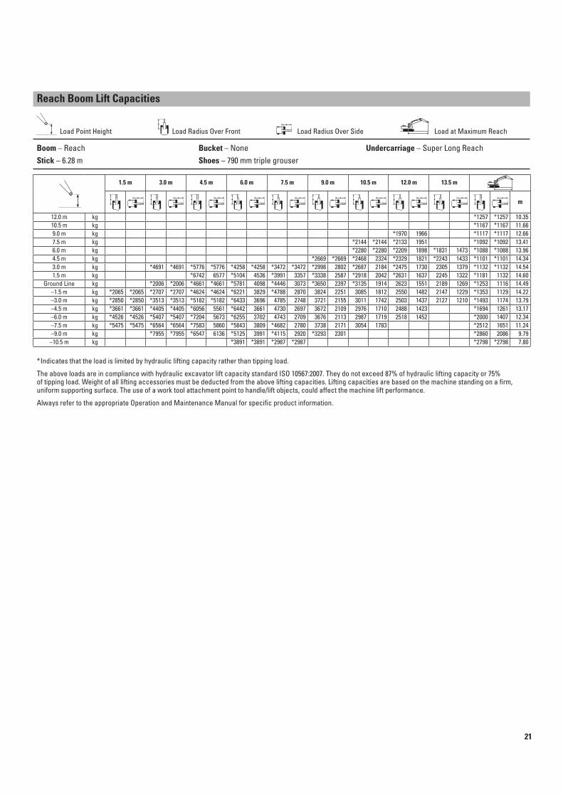
Reach Boom Lift Capacities
Load Point Height Load Radius Over Front Load Radius Over Side Load at Maximum Reach
Boom – Reach Bucket – None Undercarriage – Super Long Reach
Stick – 6.28 m Shoes – 790 mm triple grouser
1.5 m 3.0 m 4.5 m 6.0 m 7.5 m 9.0 m 10.5 m 12.0 m 13.5 m
m
12.0 m kg *1257 *1257 10.35
10.5 m kg *1167 *1167 11.66
9.0 m kg *1970 1966 *1117 *1117 12.66
7.5 m kg *2144 *2144 *2133 1951 *1092 *1092 13.41
6.0 m kg *2280 *2280 *2209 1898 *1831 1473 *1088 *1088 13.96
4.5 m kg *2669 *2669 *2468 2324 *2329 1821 *2243 1433 *1101 *1101 14.34
3.0 m kg *4691 *4691 *5776 *5776 *4258 *4258 *3472 *3472 *2998 2802 *2687 2184 *2475 1730 2305 1379 *1132 *1132 14.54
1.5 m kg *6742 6577 *5104 4536 *3991 3357 *3338 2587 *2918 2042 *2631 1637 2245 1322 *1181 1132 14.60
Ground Line kg *2006 *2006 *4661 *4661 *5781 4098 *4446 3073 *3650 2397 *3135 1914 2623 1551 2189 1269 *1253 1116 14.49
–1.5 m kg *2065 *2065 *2707 *2707 *4624 *4624 *6221 3829 *4788 2870 3824 2251 3085 1812 2550 1482 2147 1229 *1353 1129 14.22
–3.0 m kg *2850 *2850 *3513 *3513 *5182 *5182 *6433 3696 4785 2748 3721 2155 3011 1742 2503 1437 2127 1210 *1493 1174 13.79
–4.5 m kg *3661 *3661 *4405 *4405 *6056 5561 *6442 3661 4730 2697 3672 2109 2976 1710 2488 1423 *1694 1261 13.17
–6.0 m kg *4526 *4526 *5407 *5407 *7204 5673 *6255 3702 4743 2709 3676 2113 2987 1719 2518 1452 *2000 1407 12.34
–7.5 m kg *5475 *5475 *6564 *6564 *7583 5860 *5843 3809 *4682 2780 3738 2171 3054 1783 *2512 1651 11.24
–9.0 m kg *7955 *7955 *6547 6136 *5125 3991 *4115 2920 *3293 2301 *2860 2086 9.79
–10.5 m kg *3891 *3891 *2987 *2987 *2798 *2798 7.80
*Indicates that the load is limited by hydraulic lifting capacity rather than tipping load.
The above loads are in compliance with hydraulic excavator lift capacity standard ISO 10567:2007. They do not exceed 87% of hydraulic lifting capacity or 75%of tipping load. Weight of all lifting accessories must be deducted from the above lifting capacities. Lifting capacities are based on the machine standing on a firm,uniform supporting surface. The use of a work tool attachment point to handle/lift objects, could affect the machine lift performance.
Always refer to the appropriate Operation and Maintenance Manual for specific product information.
21

320D/320D L Specifications
Reach Boom Lift Capacities
Load Point Height Load Radius Over Front Load Radius Over Side Load at Maximum Reach
Boom – Reach Bucket – None Undercarriage – Standard
Stick – 2.5 m Shoes – 600 mm triple grouser
1.5 m 3.0 m 4.5 m 6.0 m 7.5 m
m
7.5 m kg *4700 *4700 5.59
6.0 m kg *5200 4550 *4300 3600 6.83
4.5 m kg *6600 *6600 *5650 4400 4550 3050 *4200 3000 7.57
3.0 m kg *8250 6250 6250 4150 4450 2950 4050 2650 7.96
1.5 m kg 9250 5750 6000 3900 4300 2850 3900 2550 8.05
Ground Line kg 9000 5500 5800 3750 4250 2750 4000 2600 7.86
–1.5 m kg *11 300 10 450 8950 5500 5750 3700 4350 2850 7.35
–3.0 m kg *12 800 10 650 9050 5600 5850 3750 5300 3450 6.46
–4.5 m kg *6900 5850 *5950 5150 4.98
Boom – Reach Bucket – None Undercarriage – Standard
Stick – 2.5 m Shoes – 790 mm triple grouser
1.5 m 3.0 m 4.5 m 6.0 m 7.5 m
m
7.5 m kg *4700 *4700 5.59
6.0 m kg *5200 4650 *4300 3700 6.83
4.5 m kg *6600 *6600 *5650 4500 4650 3100 *4200 3050 7.57
3.0 m kg *8250 6400 *6350 4250 4550 3050 4150 2750 7.96
1.5 m kg 9500 5900 6150 4000 4450 2900 4000 2650 8.05
Ground Line kg 9250 5650 6000 3850 4350 2850 4100 2650 7.86
–1.5 m kg *11 300 10 750 9200 5650 5950 3800 4500 2900 7.35
–3.0 m kg *12 800 10 950 *9300 5750 6000 3850 5450 3550 6.46
–4.5 m kg *6900 6050 *5950 5250 4.98
*Indicates that the load is limited by hydraulic lifting capacity rather than tipping load.
The above loads are in compliance with hydraulic excavator lift capacity standard ISO 10567:2007. They do not exceed 87% of hydraulic lifting capacity or 75%of tipping load. Weight of all lifting accessories must be deducted from the above lifting capacities. Lifting capacities are based on the machine standing on a firm,uniform supporting surface. The use of a work tool attachment point to handle/lift objects, could affect the machine lift performance.
Always refer to the appropriate Operation and Maintenance Manual for specific product information.
22

Reach Boom Lift Capacities
Load Point Height Load Radius Over Front Load Radius Over Side Load at Maximum Reach
Boom – Reach Bucket – None Undercarriage – Long
Stick – 2.5 m Shoes – 790 mm triple grouser
1.5 m 3.0 m 4.5 m 6.0 m 7.5 m
m
7.5 m kg *4700 *4700 5.59
6.0 m kg *5200 5150 *4300 4100 6.83
4.5 m kg *6600 *6600 *5650 5000 *4750 3450 *4200 3400 7.57
3.0 m kg *8250 7200 *6350 4750 5400 3400 *4300 3100 7.96
1.5 m kg *9750 6700 *7100 4500 5250 3250 *4600 2950 8.05
Ground Line kg *10 350 6450 7150 4300 5200 3200 4850 3000 7.86
–1.5 m kg *11 300 *11 300 *10 200 6400 7100 4250 5350 3300 7.35
–3.0 m kg *12 800 12 650 *9300 6500 *6850 4350 *6100 3950 6.46
–4.5 m kg *6900 6800 *5950 5900 4.98
Boom – Reach Bucket – None Undercarriage – Long
Stick – 2.5 m Shoes – 600 mm triple grouser
1.5 m 3.0 m 4.5 m 6.0 m 7.5 m
m
7.5 m kg *4700 *4700 5.59
6.0 m kg *5200 5000 *4300 4000 6.83
4.5 m kg *6600 *6600 *5650 4850 *4750 3400 *4200 3300 7.57
3.0 m kg *8250 7000 *6350 4600 5250 3300 *4300 3000 7.96
1.5 m kg *9750 6500 *7100 4350 5100 3200 4600 2850 8.05
Ground Line kg *10 350 6250 6950 4200 5050 3100 4700 2900 7.86
–1.5 m kg *11 300 *11 300 *10 200 6200 6900 4150 5150 3200 7.35
–3.0 m kg *12 800 12 300 *9300 6300 *6850 4200 *6100 3850 6.46
–4.5 m kg *6900 6600 *5950 5750 4.98
*Indicates that the load is limited by hydraulic lifting capacity rather than tipping load.
The above loads are in compliance with hydraulic excavator lift capacity standard ISO 10567:2007. They do not exceed 87% of hydraulic lifting capacity or 75%of tipping load. Weight of all lifting accessories must be deducted from the above lifting capacities. Lifting capacities are based on the machine standing on a firm,uniform supporting surface. The use of a work tool attachment point to handle/lift objects, could affect the machine lift performance.
Always refer to the appropriate Operation and Maintenance Manual for specific product information.
23

320D/320D L Specifications
Reach Boom Lift Capacities
Load Point Height Load Radius Over Front Load Radius Over Side Load at Maximum Reach
Boom – Reach Bucket – None Undercarriage – Long
Stick – 2.5 m Shoes – 790 mm triple grouser
1.5 m 3.0 m 4.5 m 6.0 m 7.5 m
m
7.5 m kg *4674 *4674 5.59
6.0 m kg *5180 *5180 *4279 *4279 6.83
4.5 m kg *6547 *6547 *5593 5276 *4724 3680 *4188 3623 7.57
3.0 m kg *8210 7628 *6318 5019 *5464 3591 *4289 3266 7.96
1.5 m kg *9667 7105 *7051 4768 5538 3478 *4575 3135 8.05
Ground Line kg *10 303 6856 *7518 4602 5451 3398 5107 3194 7.86
–1.5 m kg *11 265 *11 265 *10 155 6813 7489 4546 5605 3487 7.35
–3.0 m kg *12 715 *12 715 *9222 6916 *6791 4622 *6064 4213 6.46
–4.5 m kg *6819 *6819 *5895 *5895 4.98
Boom – Reach Bucket – None Undercarriage – Long
Stick – 2.5 m Shoes – 790 mm triple grouser
1.5 m 3.0 m 4.5 m 6.0 m 7.5 m
m
7.5 m kg *4816 *4816 5.59
6.0 m kg *5361 *5361 *4411 4360 6.83
4.5 m kg *6770 *6770 *5789 5276 *4869 3680 *4318 3623 7.57
3.0 m kg *8497 7628 *6542 5019 *5661 3591 *4422 3266 7.96
1.5 m kg *10 008 7105 *7303 4768 5538 3478 *4717 3135 8.05
Ground Line kg *10 668 6856 7551 4602 5451 3398 5107 3194 7.86
–1.5 m kg *11 596 *11 596 *10 517 6813 7489 4546 5605 3487 7.35
–3.0 m kg *13 173 *13 173 *9555 6916 *7039 4622 *6288 4213 6.46
–4.5 m kg *7076 *7076 *6119 *6119 4.98
*Indicates that the load is limited by hydraulic lifting capacity rather than tipping load.
The above loads are in compliance with hydraulic excavator lift capacity standard ISO 10567:2007. They do not exceed 87% of hydraulic lifting capacity or 75%of tipping load. Weight of all lifting accessories must be deducted from the above lifting capacities. Lifting capacities are based on the machine standing on a firm,uniform supporting surface. The use of a work tool attachment point to handle/lift objects, could affect the machine lift performance.
Always refer to the appropriate Operation and Maintenance Manual for specific product information.
24

Reach Boom Lift Capacities
Load Point Height Load Radius Over Front Load Radius Over Side Load at Maximum Reach
Boom – Reach Bucket – None Undercarriage – Long
Stick – 2.5 m Shoes – 600 mm triple grouser
1.5 m 3.0 m 4.5 m 6.0 m 7.5 m
m
7.5 m kg *4674 *4674 5.59
6.0 m kg *5180 *5180 *4279 4251 6.83
4.5 m kg *6547 *6547 *5593 5148 *4724 3583 *4188 3526 7.57
3.0 m kg *8210 7440 *6318 4891 *5464 3494 *4289 3176 7.96
1.5 m kg *9667 6918 *7051 4640 5385 3381 *4575 3045 8.05
Ground Line kg *10 303 6669 7343 4474 5298 3301 4962 3102 7.86
–1.5 m kg *11 265 *11 265 *10 155 6625 7280 4418 5447 3388 7.35
–3.0 m kg *12 715 *12 715 *9222 6729 *6791 4494 *6064 4096 6.46
–4.5 m kg *6819 *6819 *5895 *5895 4.98
Boom – Reach Bucket – None Undercarriage – Long
Stick – 2.5 m Shoes – 600 mm triple grouser
1.5 m 3.0 m 4.5 m 6.0 m 7.5 m
m
7.5 m kg *4816 *4816 5.59
6.0 m kg *5361 5310 *4411 4251 6.83
4.5 m kg *6770 *6770 *5789 5148 *4869 3583 *4318 3526 7.57
3.0 m kg *8497 7440 *6542 4891 5509 3494 *4422 3176 7.96
1.5 m kg *10 008 6918 *7303 4640 5385 3381 *4717 3045 8.05
Ground Line kg *10 668 6669 7343 4474 5298 3301 4962 3102 7.86
–1.5 m kg *11 596 *11 596 *10 517 6625 7280 4418 5447 3388 7.35
–3.0 m kg *13 173 13 109 *9555 6729 *7039 4494 *6288 4096 6.46
–4.5 m kg *7076 7035 *6119 6115 4.98
*Indicates that the load is limited by hydraulic lifting capacity rather than tipping load.
The above loads are in compliance with hydraulic excavator lift capacity standard ISO 10567:2007. They do not exceed 87% of hydraulic lifting capacity or 75%of tipping load. Weight of all lifting accessories must be deducted from the above lifting capacities. Lifting capacities are based on the machine standing on a firm,uniform supporting surface. The use of a work tool attachment point to handle/lift objects, could affect the machine lift performance.
Always refer to the appropriate Operation and Maintenance Manual for specific product information.
25

320D/320D L Standard Equipment
Standard equipment may vary. Consult your Cat dealer for details.
Upper Structure
Electrical
Alternator, 80 Amp
Light, storage box mounted (one)
Signaling/Warning horn
Starter Motor 8 kW
Engine
C6.6 with ACERT™ Technology
3000 m altitude capability
with no deration
4 fuel $ltrations (4 micron)
China Beijing and China National
Emission package
Mandatory to meet Beijing Emissions
Regulation DB 11/185-2003,
DB11/184-2003 and China National
Standard GB 17691-2001
Glow plug
Automatic engine speed control with
one touch low idle
High ambient cooling package (for China)
Radial seal air $lter
Water separator in fuel line with 4 micron
fuel $lter with water level indicator
Waved $n radiator with space for cleaning
Auxiliary hydraulic valve (one)
Automatic swing parking brake
Batteries (2× 900 cca)
Boom drift reducing valve
Boom lowering device for back-up
Capability of stackable valves for main
valve (maximum three valves)
Capability of auxiliary circuit
(auxiliary pump and valves)
Capability of boom and stick lowering
control device
Cat data link with capability of E.T.
Cat one key security system
Counterweight
Door locks and cap locks
Fixed type condenser core for
air conditioning
Mirrors, rearview (frame-right, cab-left)
Product Link (China) – 522
Regeneration circuit for boom and stick
Reverse swing damping valve
Secondary engine shutoff switch
Steel wall between engine and pump
compartment
Stick drift reducing valve
Straight travel hydraulic circuit
Two speed travel
Undercarriage
Idler and center section track guiding
Towing eye on base frame
Operator Station
Cab
Adjustable armrest
Antenna and Harness
(without radio speakers)
Ashtray and lighter
Beverage holder
Bi-Level air conditioner (automatic)
with defroster
Capability of installing
two additional pedals
Coat hook
Front windshield glass split 70/30
Interior lighting
Control lever joysticks
Laminated front windshield and
tempered other windows
Literature holder
Mounting for two stereo speakers
(two locations)
Neutral lever (lock out) for all controls
Openable front windshield with
assist device
Openable metal roof hatch
Pillar mounted upper windshield
wiper and washer
Positive $ltered ventilation
Pressurized cab (Positive $ltered
ventilation)
Radio mounting (DIN size)
Rear window, emergency exit
Removable lower windshield with in-cab
storage bracket
Seat suspension, four way adjustable low
back with integrated, adjustable console
Seat belt, retractable (two inch width)
Sliding upper door window
Start Switch Panel
Travel control pedals with removable
hand levers
Utility space for magazine
Washable #oor mat
Monitor
Economy mode
Full time clock
Language display – Full color and
graphical display
Machine condition, error code and
tool mode setting
Start-up level check for hydraulic oil,
engine oil and coolant
Warning information, $lter/#uid change
information and working hour
26

320D/320D L Optional Equipment
Optional equipment may vary. Consult your Cat dealer for details.
Front Linkage
Bucket linkage, B1-family
Heavy-duty 5.7 m reach boom
(with left side light)
Heavy-duty R2.9B1 stick for heavy-duty
reach boom
Heavy-duty R2.5B1 stick for heavy-duty
reach boom
Super long reach arrangement
(only for 320D L)
Bucket
General duty 1.0 m3
Heavy duty 1.0 m3
Heavy duty 1.2 m3
Severe duty 1.0 m3
General duty 0.4 m3 for super long reach
arrangement
Ditch cleaning 0.6 m3 for super long reach
arrangement
Bucket attachments
Tips, side cutters and side protectors
Tracks
600 mm double grouser shoes
600 mm triple grouser shoes
790 mm triple grouser shoes
Ether aid for cold weather package
Auxiliary hydraulics and lines
Boom and stick lines
Tool control system
Common, 1 way and 2 ways
Foot pedals operated 1/2P, common
circuit for sheers, pulverizes, thumbs,
cutter etc.
Hammer, 1 way only
Foot pedal operated 2P, one way circuit
for hammers, pile drivers etc.
Starting kit, cold weather,
additional 2×batteries
Full length track guiding guard
Air pre$lter
Converter (2 sockets, max 10A)
Guard Package include (HD) Bottom,
(HD) travel motor, swivel
HD roller
Cab light
27

320D/320D L Hydraulic Excavators
For more complete information on Cat products, dealer services, and industry solutions,
visit us on the web at www.cat.com
© 2011 Caterpillar Inc.
All rights reserved
Materials and speci$cations are subject to change without notice. Featured machines
in photos may include additional equipment. See your Cat dealer for available options.
CAT, CATERPILLAR, SAFETY.CAT.COM, their respective logos, “Caterpillar Yellow”
and the “Power Edge” trade dress, as well as corporate and product identity used herein,
are trademarks of Caterpillar and may not be used without permission.
AEHQ6445 (11-2011)
(GCN1)