307-01-Automatic Transaxle-Transmission - 5R55S...
49
Transmission SECTION 307-01: Automatic Transaxle/Transmission — 5R55S 2009 Mustang Workshop Manual ASSEMBLY Procedure revision date: 06/30/2009 Special Tool(s) Adjustment Set, Transmission Band 307-S022 (T71P-77370-A) Air Test Plate and Gaskets, Transmission 307-433-01, 307-433-02, 307-433- 03 Aligner, Flex Plate 307-403 Aligner, Valve Body 307-334 (T95L-70010-C) Alignment Gauge, Transmission Fluid Pump 307-431 Alignment Gauge, Transmission Fluid Pump 307-432 Alignment Gauge, TR Sensor 307-351 (T97L-70010-A) Alignment Pins, Transmission Fluid Pump 307-399
Transcript of 307-01-Automatic Transaxle-Transmission - 5R55S...

Transmission
SECTION 307-01: Automatic Transaxle/Transmission — 5R55S 2009 Mustang Workshop Manual ASSEMBLY Procedure revision date: 06/30/2009
Special Tool(s)
Adjustment Set, Transmission Band 307-S022 (T71P-77370-A)
Air Test Plate and Gaskets, Transmission 307-433-01, 307-433-02, 307-433-03
Aligner, Flex Plate 307-403
Aligner, Valve Body 307-334 (T95L-70010-C)
Alignment Gauge, Transmission Fluid Pump 307-431
Alignment Gauge, Transmission Fluid Pump 307-432
Alignment Gauge, TR Sensor 307-351 (T97L-70010-A)
Alignment Pins, Transmission Fluid Pump 307-399
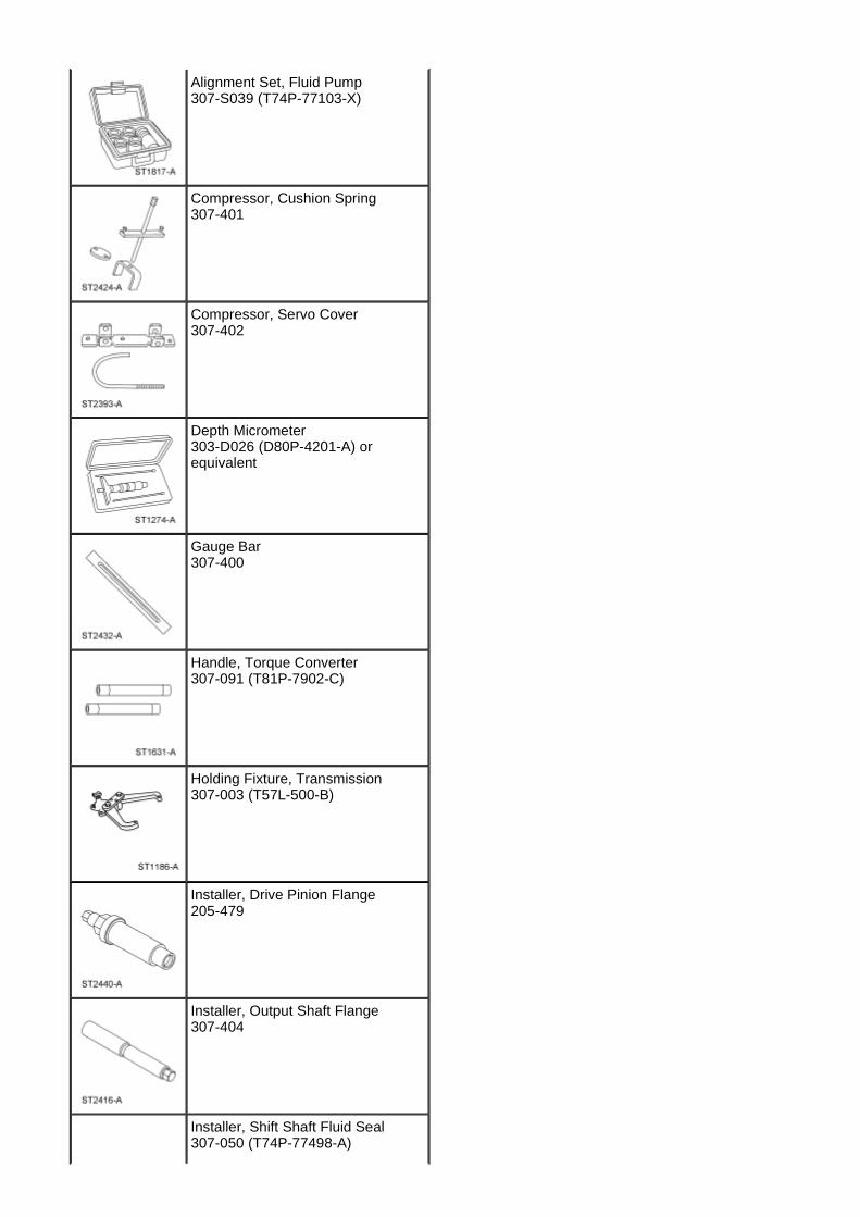
Alignment Set, Fluid Pump 307-S039 (T74P-77103-X)
Compressor, Cushion Spring 307-401
Compressor, Servo Cover 307-402
Depth Micrometer 303-D026 (D80P-4201-A) or equivalent
Gauge Bar 307-400
Handle, Torque Converter 307-091 (T81P-7902-C)
Holding Fixture, Transmission 307-003 (T57L-500-B)
Installer, Drive Pinion Flange 205-479
Installer, Output Shaft Flange 307-404
Installer, Shift Shaft Fluid Seal 307-050 (T74P-77498-A)
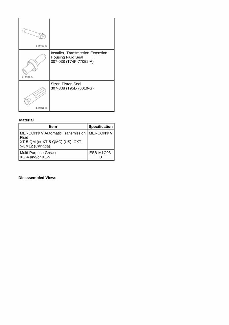
Disassembled Views
Installer, Transmission Extension Housing Fluid Seal 307-038 (T74P-77052-A)
Sizer, Piston Seal 307-338 (T95L-70010-G)
Material
Item Specification
MERCON® V Automatic Transmission Fluid XT-5-QM (or XT-5-QMC) (US); CXT-5-LM12 (Canada)
MERCON® V
Multi-Purpose Grease XG-4 and/or XL-5
ESB-M1C93-B
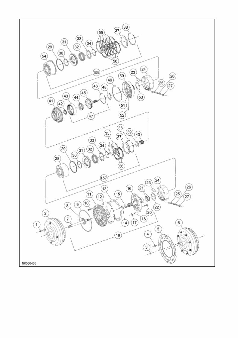
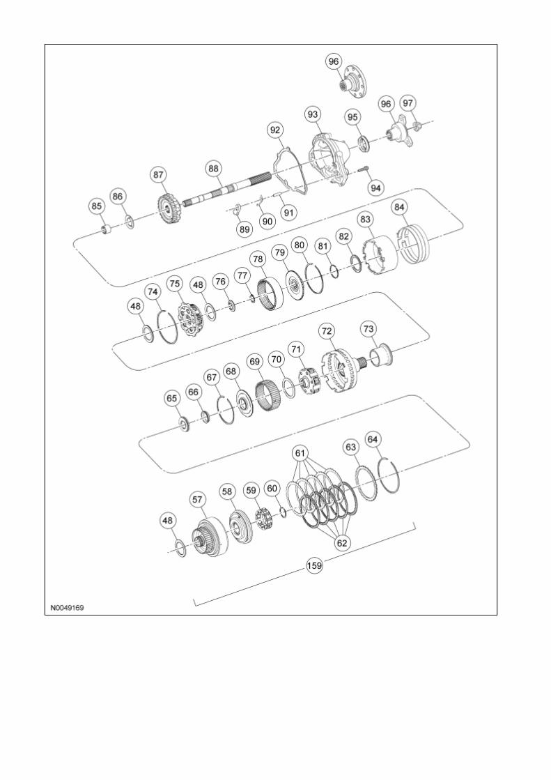
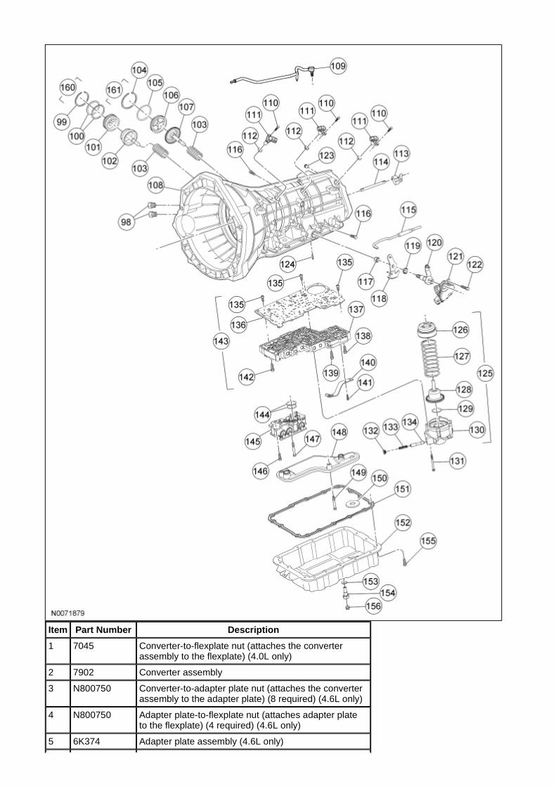
Item Part Number Description
1 7045 Converter-to-flexplate nut (attaches the converter assembly to the flexplate) (4.0L only)
2 7902 Converter assembly
3 N800750 Converter-to-adapter plate nut (attaches the converter assembly to the adapter plate) (8 required) (4.6L only)
4 N800750 Adapter plate-to-flexplate nut (attaches adapter plate to the flexplate) (4 required) (4.6L only)
5 6K374 Adapter plate assembly (4.6L only)
6 7902 Converter assembly
7 7017 Input shaft
8 7A248 Front fluid pump seal assembly
9 7A248 Front fluid pump seal
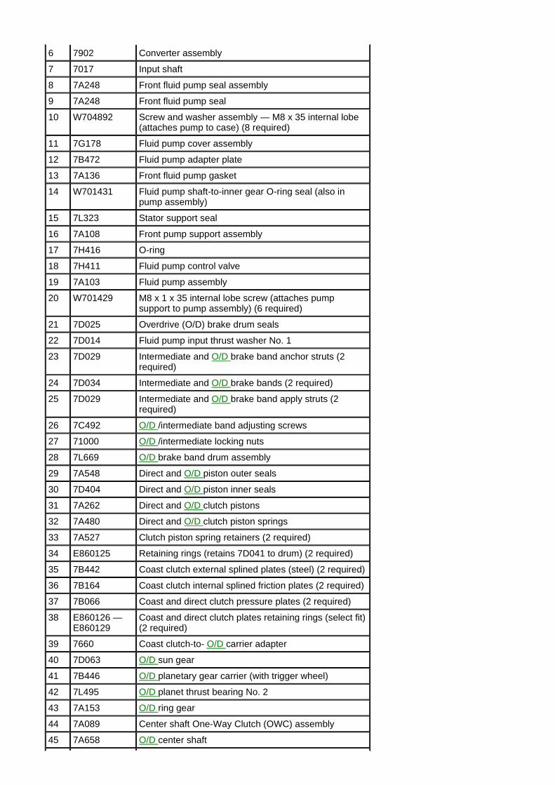
10 W704892 Screw and washer assembly — M8 x 35 internal lobe (attaches pump to case) (8 required)
11 7G178 Fluid pump cover assembly
12 7B472 Fluid pump adapter plate
13 7A136 Front fluid pump gasket
14 W701431 Fluid pump shaft-to-inner gear O-ring seal (also in pump assembly)
15 7L323 Stator support seal
16 7A108 Front pump support assembly
17 7H416 O-ring
18 7H411 Fluid pump control valve
19 7A103 Fluid pump assembly
20 W701429 M8 x 1 x 35 internal lobe screw (attaches pump support to pump assembly) (6 required)
21 7D025 Overdrive (O/D) brake drum seals
22 7D014 Fluid pump input thrust washer No. 1
23 7D029 Intermediate and O/D brake band anchor struts (2 required)
24 7D034 Intermediate and O/D brake bands (2 required)
25 7D029 Intermediate and O/D brake band apply struts (2 required)
26 7C492 O/D /intermediate band adjusting screws
27 71000 O/D /intermediate locking nuts
28 7L669 O/D brake band drum assembly
29 7A548 Direct and O/D piston outer seals
30 7D404 Direct and O/D piston inner seals
31 7A262 Direct and O/D clutch pistons
32 7A480 Direct and O/D clutch piston springs
33 7A527 Clutch piston spring retainers (2 required)
34 E860125 Retaining rings (retains 7D041 to drum) (2 required)
35 7B442 Coast clutch external splined plates (steel) (2 required)
36 7B164 Coast clutch internal splined friction plates (2 required)
37 7B066 Coast and direct clutch pressure plates (2 required)
38 E860126 — E860129
Coast and direct clutch plates retaining rings (select fit) (2 required)
39 7660 Coast clutch-to- O/D carrier adapter
40 7D063 O/D sun gear
41 7B446 O/D planetary gear carrier (with trigger wheel)
42 7L495 O/D planet thrust bearing No. 2
43 7A153 O/D ring gear
44 7A089 Center shaft One-Way Clutch (OWC) assembly
45 7A658 O/D center shaft
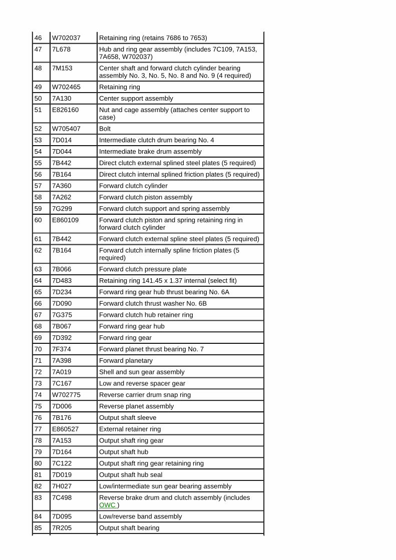
46 W702037 Retaining ring (retains 7686 to 7653)
47 7L678 Hub and ring gear assembly (includes 7C109, 7A153, 7A658, W702037)
48 7M153 Center shaft and forward clutch cylinder bearing assembly No. 3, No. 5, No. 8 and No. 9 (4 required)
49 W702465 Retaining ring
50 7A130 Center support assembly
51 E826160 Nut and cage assembly (attaches center support to case)
52 W705407 Bolt
53 7D014 Intermediate clutch drum bearing No. 4
54 7D044 Intermediate brake drum assembly
55 7B442 Direct clutch external splined steel plates (5 required)
56 7B164 Direct clutch internal splined friction plates (5 required)
57 7A360 Forward clutch cylinder
58 7A262 Forward clutch piston assembly
59 7G299 Forward clutch support and spring assembly
60 E860109 Forward clutch piston and spring retaining ring in forward clutch cylinder
61 7B442 Forward clutch external spline steel plates (5 required)
62 7B164 Forward clutch internally spline friction plates (5 required)
63 7B066 Forward clutch pressure plate
64 7D483 Retaining ring 141.45 x 1.37 internal (select fit)
65 7D234 Forward ring gear hub thrust bearing No. 6A
66 7D090 Forward clutch thrust washer No. 6B
67 7G375 Forward clutch hub retainer ring
68 7B067 Forward ring gear hub
69 7D392 Forward ring gear
70 7F374 Forward planet thrust bearing No. 7
71 7A398 Forward planetary
72 7A019 Shell and sun gear assembly
73 7C167 Low and reverse spacer gear
74 W702775 Reverse carrier drum snap ring
75 7D006 Reverse planet assembly
76 7B176 Output shaft sleeve
77 E860527 External retainer ring
78 7A153 Output shaft ring gear
79 7D164 Output shaft hub
80 7C122 Output shaft ring gear retaining ring
81 7D019 Output shaft hub seal
82 7H027 Low/intermediate sun gear bearing assembly
83 7C498 Reverse brake drum and clutch assembly (includes OWC )
84 7D095 Low/reverse band assembly
85 7R205 Output shaft bearing
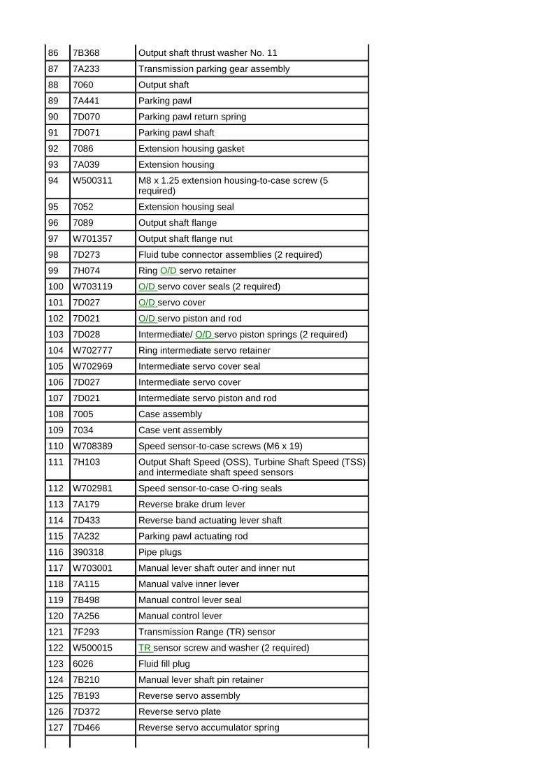
86 7B368 Output shaft thrust washer No. 11
87 7A233 Transmission parking gear assembly
88 7060 Output shaft
89 7A441 Parking pawl
90 7D070 Parking pawl return spring
91 7D071 Parking pawl shaft
92 7086 Extension housing gasket
93 7A039 Extension housing
94 W500311 M8 x 1.25 extension housing-to-case screw (5 required)
95 7052 Extension housing seal
96 7089 Output shaft flange
97 W701357 Output shaft flange nut
98 7D273 Fluid tube connector assemblies (2 required)
99 7H074 Ring O/D servo retainer
100 W703119 O/D servo cover seals (2 required)
101 7D027 O/D servo cover
102 7D021 O/D servo piston and rod
103 7D028 Intermediate/ O/D servo piston springs (2 required)
104 W702777 Ring intermediate servo retainer
105 W702969 Intermediate servo cover seal
106 7D027 Intermediate servo cover
107 7D021 Intermediate servo piston and rod
108 7005 Case assembly
109 7034 Case vent assembly
110 W708389 Speed sensor-to-case screws (M6 x 19)
111 7H103 Output Shaft Speed (OSS), Turbine Shaft Speed (TSS) and intermediate shaft speed sensors
112 W702981 Speed sensor-to-case O-ring seals
113 7A179 Reverse brake drum lever
114 7D433 Reverse band actuating lever shaft
115 7A232 Parking pawl actuating rod
116 390318 Pipe plugs
117 W703001 Manual lever shaft outer and inner nut
118 7A115 Manual valve inner lever
119 7B498 Manual control lever seal
120 7A256 Manual control lever
121 7F293 Transmission Range (TR) sensor
122 W500015 TR sensor screw and washer (2 required)
123 6026 Fluid fill plug
124 7B210 Manual lever shaft pin retainer
125 7B193 Reverse servo assembly
126 7D372 Reverse servo plate
127 7D466 Reverse servo accumulator spring
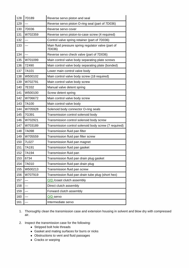
1. Thoroughly clean the transmission case and extension housing in solvent and blow dry with compressed air.
2. Inspect the transmission case for the following: � Stripped bolt hole threads � Gasket and mating surfaces for burrs or nicks � Obstructions to vent and fluid passages � Cracks or warping
128 7D189 Reverse servo piston and seal
129 — Reverse servo piston O-ring seal (part of 7D036)
130 7D036 Reverse servo cover
131 W702359 Reverse servo piston-to-case screw (4 required)
132 — Control valve spring retainer (part of 7D036)
133 — Main fluid pressure spring regulator valve (part of 7D036)
134 — Reverse servo check valve (part of 7D036)
135 W701099 Main control valve body separating plate screws
136 7Z490 Main control valve body separating plate (bonded)
137 7A101 Lower main control valve body
138 W500102 Main control valve body screw (18 required)
139 W702791 Main control valve body screw
140 7E332 Manual valve detent spring
141 W500100 Screw detent spring
142 W706672 Main control valve body screw
143 7A100 Main control valve body
144 W705928 Solenoid body connector O-ring seals
145 7G391 Transmission control solenoid body
146 W702921 Transmission control solenoid body screw
147 W703189 Transmission control solenoid body screw (7 required)
148 7A098 Transmission fluid pan filter
149 W705559 Transmission fluid pan filter screw
150 7L027 Transmission fluid pan magnet
151 7A191 Transmission fluid pan gasket
152 7A194 Transmission fluid pan
153 6734 Transmission fluid pan drain plug gasket
154 7A010 Transmission fluid pan drain plug
155 W500213 Transmission fluid pan screw
156 W707919 Transmission fluid pan drain tube plug (short hex)
157 — O/D /coast clutch assembly
158 — Direct clutch assembly
159 — Forward clutch assembly
160 — O/D servo
161 — Intermediate servo
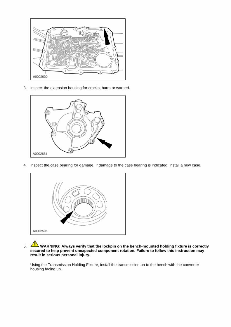
3. Inspect the extension housing for cracks, burrs or warped.
4. Inspect the case bearing for damage. If damage to the case bearing is indicated, install a new case.
5. WARNING: Always verify that the lockpin on the bench-mounted holding fixture is correctly secured to help prevent unexpected component rotation. Failure to follow this instruction may result in serious personal injury.
Using the Transmission Holding Fixture, install the transmission on to the bench with the converter housing facing up.
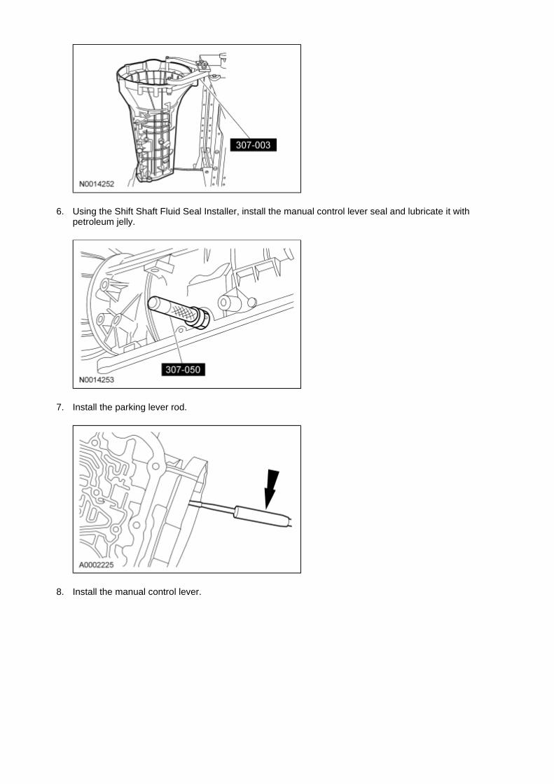
6. Using the Shift Shaft Fluid Seal Installer, install the manual control lever seal and lubricate it with petroleum jelly.
7. Install the parking lever rod.
8. Install the manual control lever.
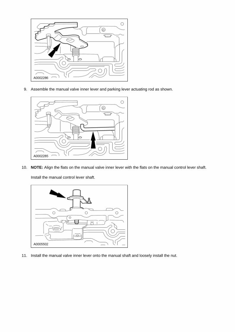
9. Assemble the manual valve inner lever and parking lever actuating rod as shown.
10. NOTE: Align the flats on the manual valve inner lever with the flats on the manual control lever shaft.
Install the manual control lever shaft.
11. Install the manual valve inner lever onto the manual shaft and loosely install the nut.
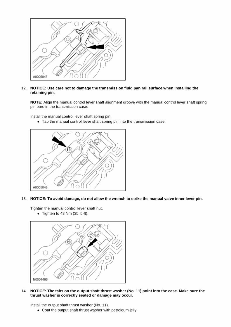
12. NOTICE: Use care not to damage the transmission fluid pan rail surface when installing the retaining pin.
NOTE: Align the manual control lever shaft alignment groove with the manual control lever shaft spring pin bore in the transmission case.
Install the manual control lever shaft spring pin. � Tap the manual control lever shaft spring pin into the transmission case.
13. NOTICE: To avoid damage, do not allow the wrench to strike the manual valve inner lever pin.
Tighten the manual control lever shaft nut. � Tighten to 48 Nm (35 lb-ft).
14. NOTICE: The tabs on the output shaft thrust washer (No. 11) point into the case. Make sure the thrust washer is correctly seated or damage may occur.
Install the output shaft thrust washer (No. 11). � Coat the output shaft thrust washer with petroleum jelly.
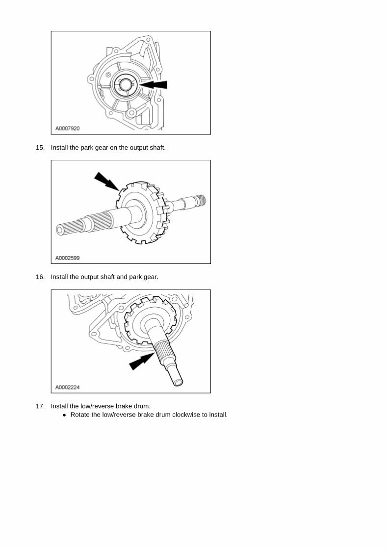
15. Install the park gear on the output shaft.
16. Install the output shaft and park gear.
17. Install the low/reverse brake drum. � Rotate the low/reverse brake drum clockwise to install.
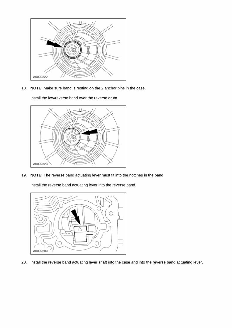
18. NOTE: Make sure band is resting on the 2 anchor pins in the case.
Install the low/reverse band over the reverse drum.
19. NOTE: The reverse band actuating lever must fit into the notches in the band.
Install the reverse band actuating lever into the reverse band.
20. Install the reverse band actuating lever shaft into the case and into the reverse band actuating lever.
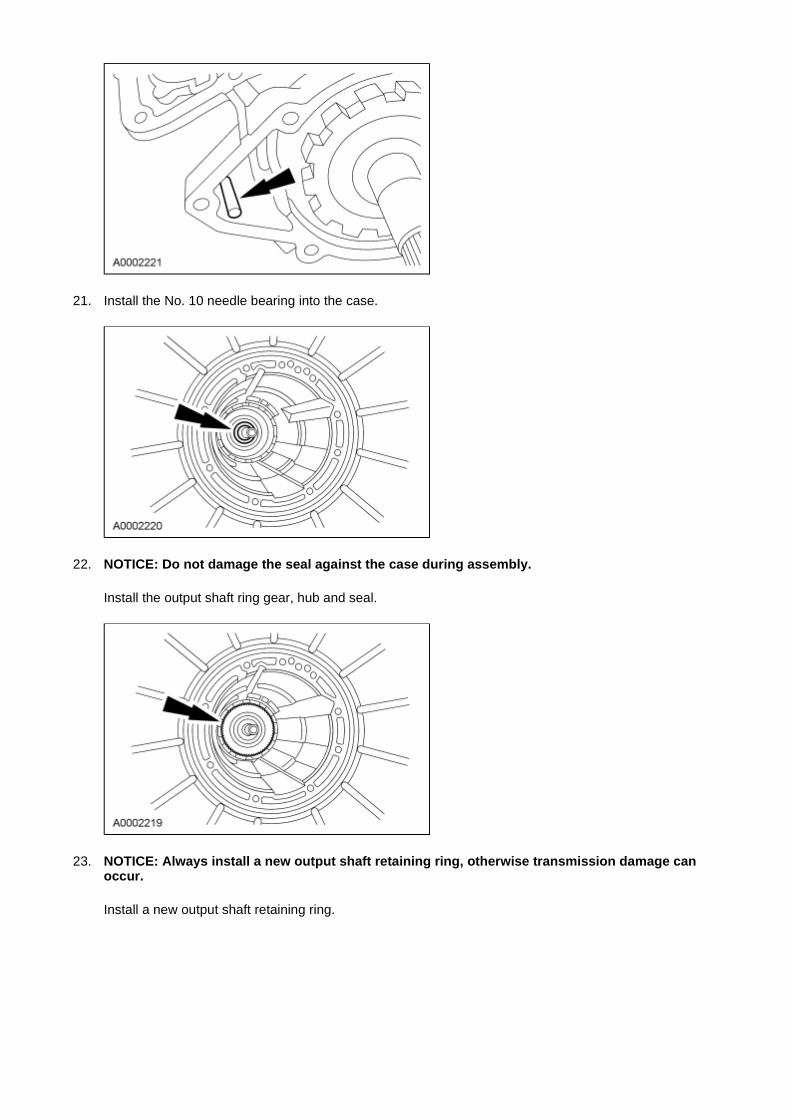
21. Install the No. 10 needle bearing into the case.
22. NOTICE: Do not damage the seal against the case during assembly.
Install the output shaft ring gear, hub and seal.
23. NOTICE: Always install a new output shaft retaining ring, otherwise transmission damage can occur.
Install a new output shaft retaining ring.
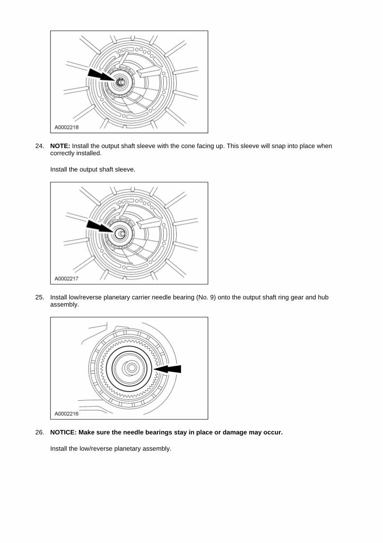
24. NOTE: Install the output shaft sleeve with the cone facing up. This sleeve will snap into place when correctly installed.
Install the output shaft sleeve.
25. Install low/reverse planetary carrier needle bearing (No. 9) onto the output shaft ring gear and hub assembly.
26. NOTICE: Make sure the needle bearings stay in place or damage may occur.
Install the low/reverse planetary assembly.
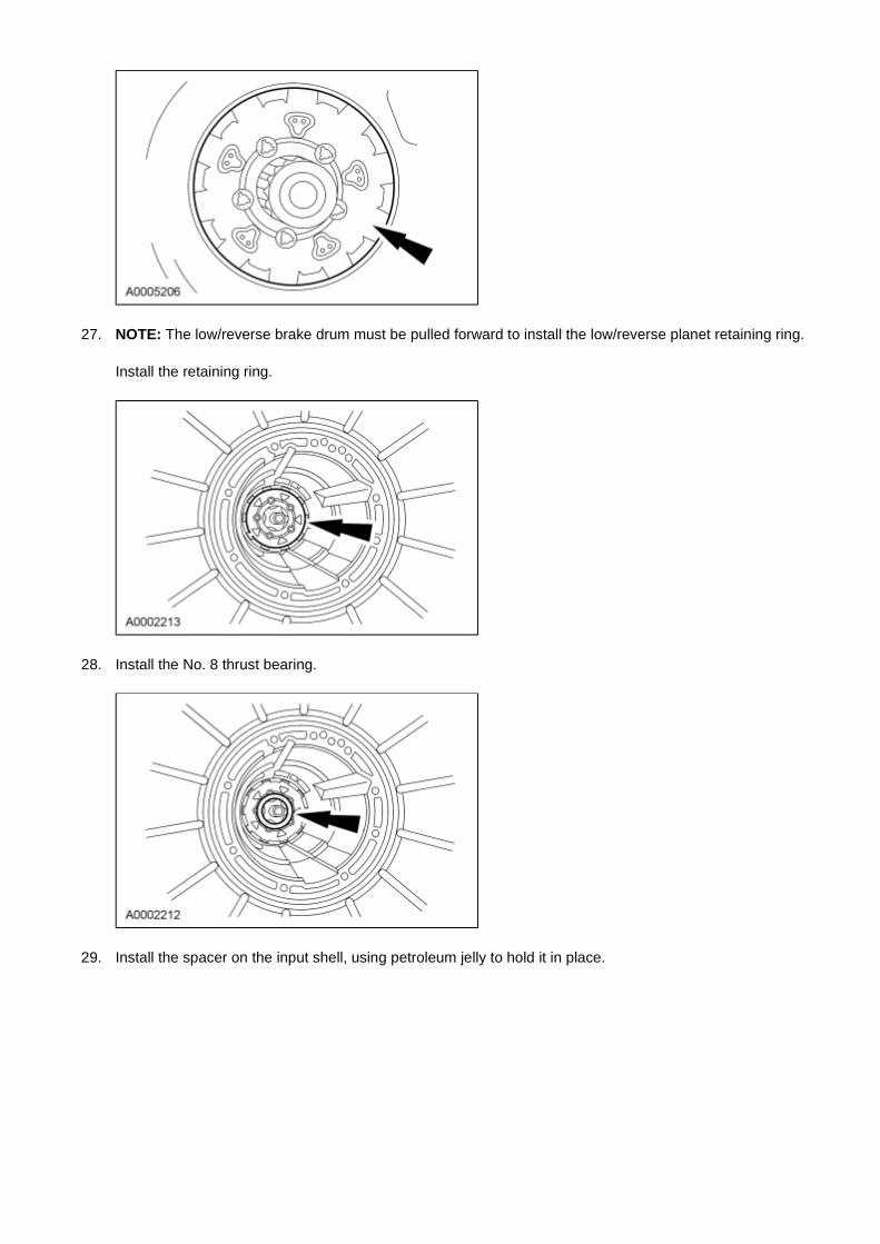
27. NOTE: The low/reverse brake drum must be pulled forward to install the low/reverse planet retaining ring.
Install the retaining ring.
28. Install the No. 8 thrust bearing.
29. Install the spacer on the input shell, using petroleum jelly to hold it in place.
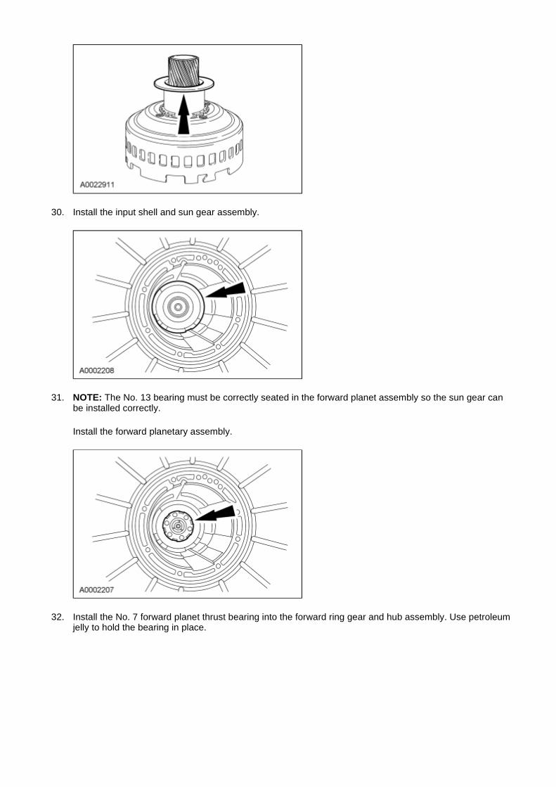
30. Install the input shell and sun gear assembly.
31. NOTE: The No. 13 bearing must be correctly seated in the forward planet assembly so the sun gear can be installed correctly.
Install the forward planetary assembly.
32. Install the No. 7 forward planet thrust bearing into the forward ring gear and hub assembly. Use petroleum jelly to hold the bearing in place.
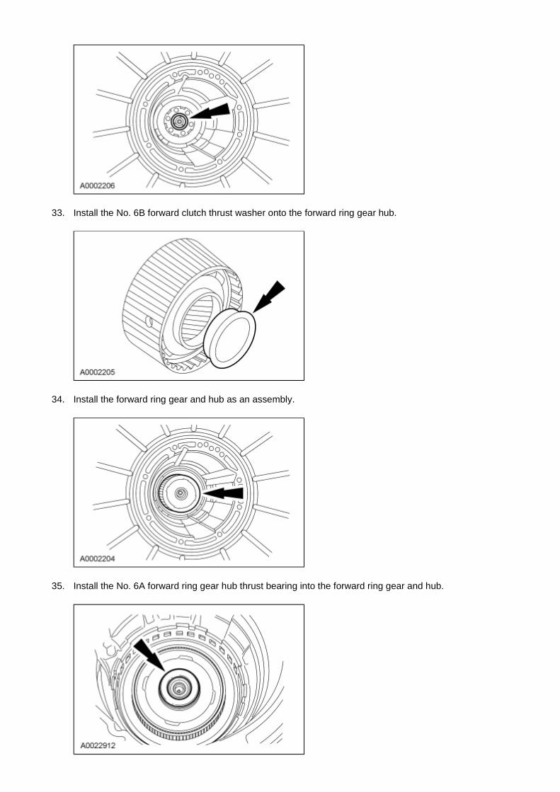
33. Install the No. 6B forward clutch thrust washer onto the forward ring gear hub.
34. Install the forward ring gear and hub as an assembly.
35. Install the No. 6A forward ring gear hub thrust bearing into the forward ring gear and hub.
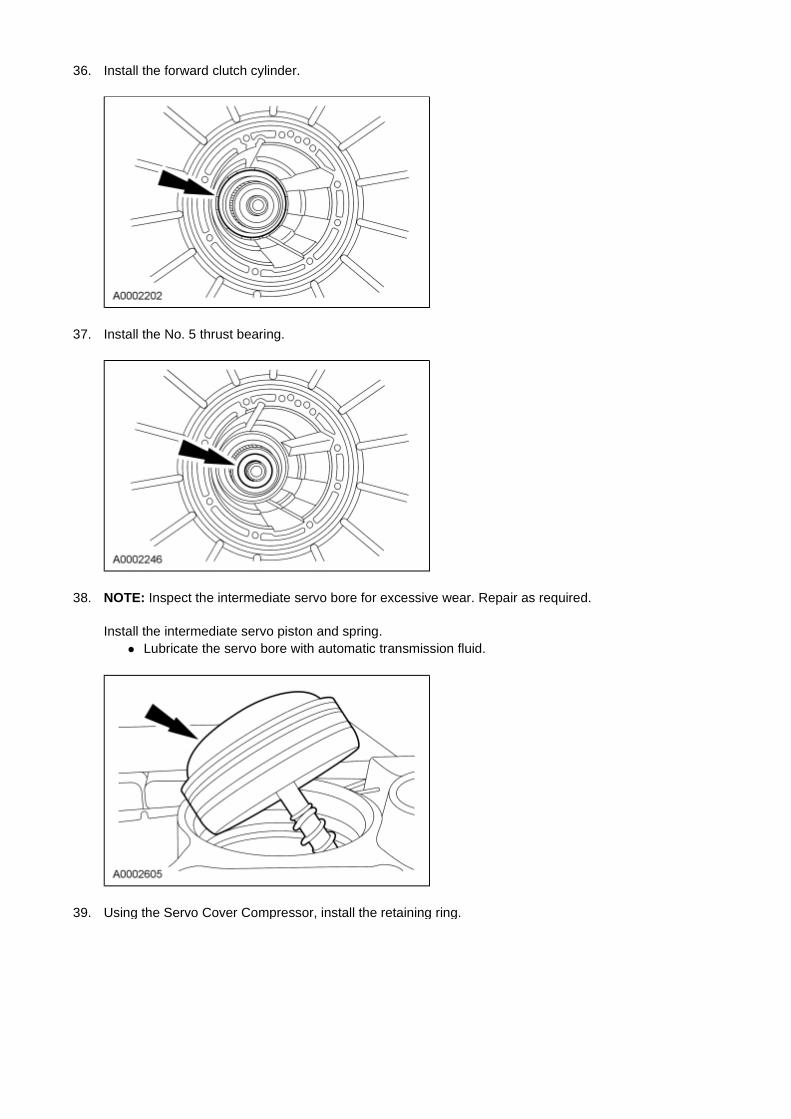
36. Install the forward clutch cylinder.
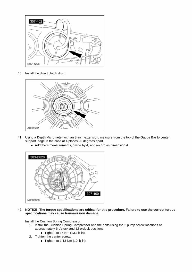
37. Install the No. 5 thrust bearing.
38. NOTE: Inspect the intermediate servo bore for excessive wear. Repair as required.
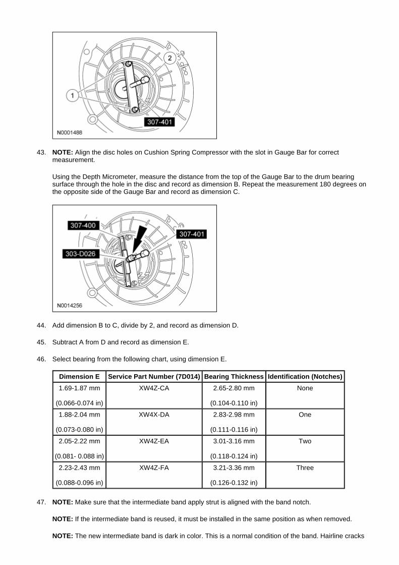
Install the intermediate servo piston and spring. � Lubricate the servo bore with automatic transmission fluid.
39. Using the Servo Cover Compressor, install the retaining ring.
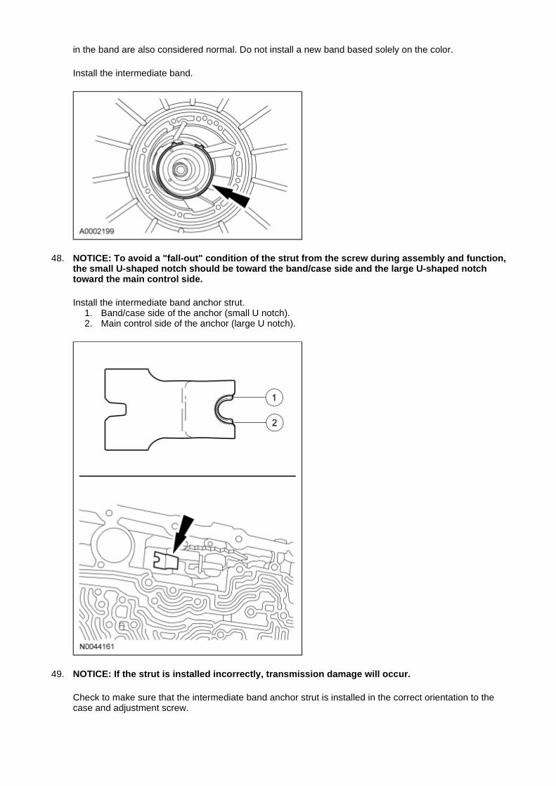
40. Install the direct clutch drum.
41. Using a Depth Micrometer with an 8-inch extension, measure from the top of the Gauge Bar to center support ledge in the case at 4 places 90 degrees apart.
� Add the 4 measurements, divide by 4, and record as dimension A.
42. NOTICE: The torque specifications are critical for this procedure. Failure to use the correct torque specifications may cause transmission damage.
Install the Cushion Spring Compressor. 1. Install the Cushion Spring Compressor and the bolts using the 2 pump screw locations at
approximately 6 o'clock and 12 o'clock positions. � Tighten to 15 Nm (133 lb-in).
2. Tighten the center screw. � Tighten to 1.13 Nm (10 lb-in).
43. NOTE: Align the disc holes on Cushion Spring Compressor with the slot in Gauge Bar for correct measurement.
Using the Depth Micrometer, measure the distance from the top of the Gauge Bar to the drum bearing surface through the hole in the disc and record as dimension B. Repeat the measurement 180 degrees on the opposite side of the Gauge Bar and record as dimension C.
44. Add dimension B to C, divide by 2, and record as dimension D.
45. Subtract A from D and record as dimension E.
46. Select bearing from the following chart, using dimension E.
47. NOTE: Make sure that the intermediate band apply strut is aligned with the band notch.
NOTE: If the intermediate band is reused, it must be installed in the same position as when removed.
NOTE: The new intermediate band is dark in color. This is a normal condition of the band. Hairline cracks
Dimension E Service Part Number (7D014) Bearing Thickness Identification (Notches)
1.69-1.87 mm
(0.066-0.074 in)
XW4Z-CA 2.65-2.80 mm
(0.104-0.110 in)
None
1.88-2.04 mm
(0.073-0.080 in)
XW4X-DA 2.83-2.98 mm
(0.111-0.116 in)
One
2.05-2.22 mm
(0.081- 0.088 in)
XW4Z-EA 3.01-3.16 mm
(0.118-0.124 in)
Two
2.23-2.43 mm
(0.088-0.096 in)
XW4Z-FA 3.21-3.36 mm
(0.126-0.132 in)
Three
in the band are also considered normal. Do not install a new band based solely on the color.
Install the intermediate band.
48. NOTICE: To avoid a "fall-out" condition of the strut from the screw during assembly and function, the small U-shaped notch should be toward the band/case side and the large U-shaped notch toward the main control side.
Install the intermediate band anchor strut. 1. Band/case side of the anchor (small U notch). 2. Main control side of the anchor (large U notch).
49. NOTICE: If the strut is installed incorrectly, transmission damage will occur.
Check to make sure that the intermediate band anchor strut is installed in the correct orientation to the case and adjustment screw.
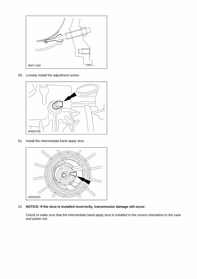
50. Loosely install the adjustment screw.
51. Install the intermediate band apply strut.
52. NOTICE: If the strut is installed incorrectly, transmission damage will occur.
Check to make sure that the intermediate band apply strut is installed in the correct orientation to the case and piston rod.
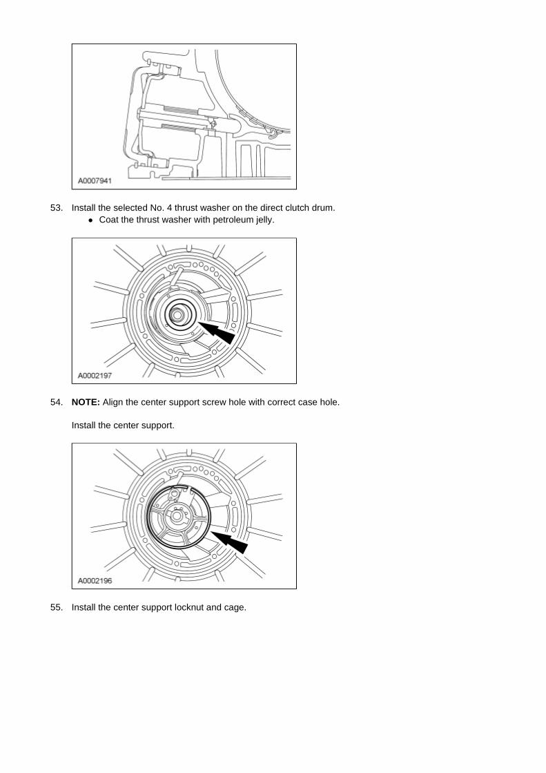
53. Install the selected No. 4 thrust washer on the direct clutch drum. � Coat the thrust washer with petroleum jelly.
54. NOTE: Align the center support screw hole with correct case hole.
Install the center support.
55. Install the center support locknut and cage.
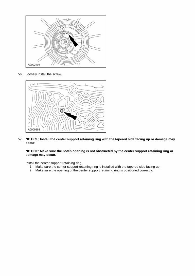
56. Loosely install the screw.
57. NOTICE: Install the center support retaining ring with the tapered side facing up or damage may occur.
NOTICE: Make sure the notch opening is not obstructed by the center support retaining ring or damage may occur.
Install the center support retaining ring. 1. Make sure the center support retaining ring is installed with the tapered side facing up. 2. Make sure the opening of the center support retaining ring is positioned correctly.

58. Install the center shaft thrust bearing (No. 3).
59. Install the O/D ring gear, O/D OWC and center shaft assembly.
60. NOTICE: Do not bend the trigger wheel. Make sure that the No. 2 thrust bearing is in this
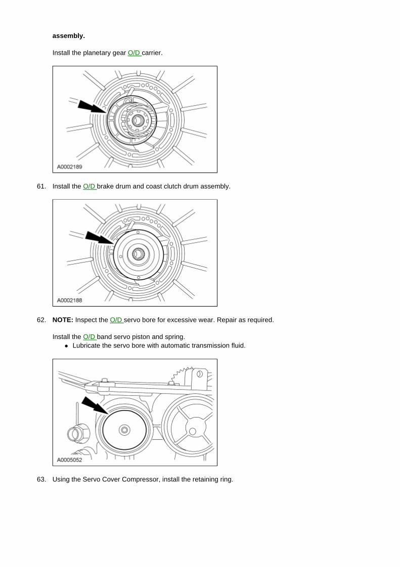
assembly.
Install the planetary gear O/D carrier.
61. Install the O/D brake drum and coast clutch drum assembly.
62. NOTE: Inspect the O/D servo bore for excessive wear. Repair as required.
Install the O/D band servo piston and spring. � Lubricate the servo bore with automatic transmission fluid.
63. Using the Servo Cover Compressor, install the retaining ring.
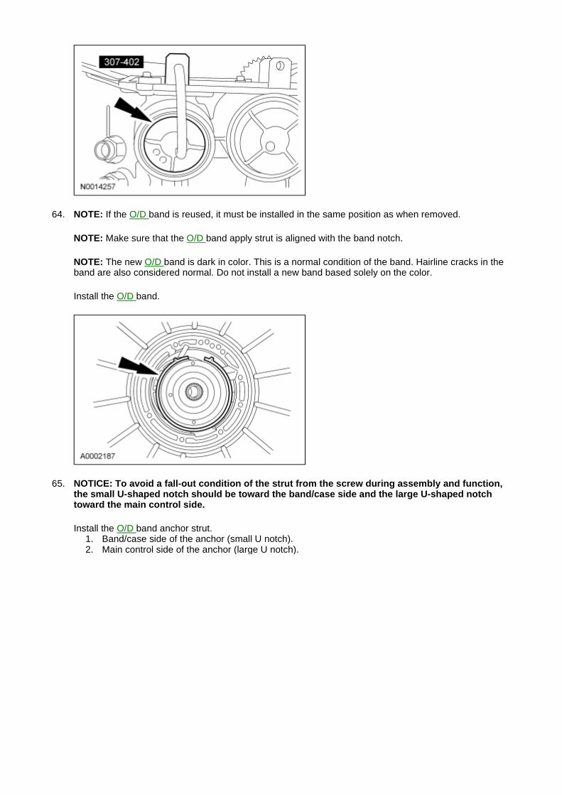
64. NOTE: If the O/D band is reused, it must be installed in the same position as when removed.
NOTE: Make sure that the O/D band apply strut is aligned with the band notch.
NOTE: The new O/D band is dark in color. This is a normal condition of the band. Hairline cracks in the band are also considered normal. Do not install a new band based solely on the color.
Install the O/D band.
65. NOTICE: To avoid a fall-out condition of the strut from the screw during assembly and function, the small U-shaped notch should be toward the band/case side and the large U-shaped notch toward the main control side.
Install the O/D band anchor strut. 1. Band/case side of the anchor (small U notch). 2. Main control side of the anchor (large U notch).
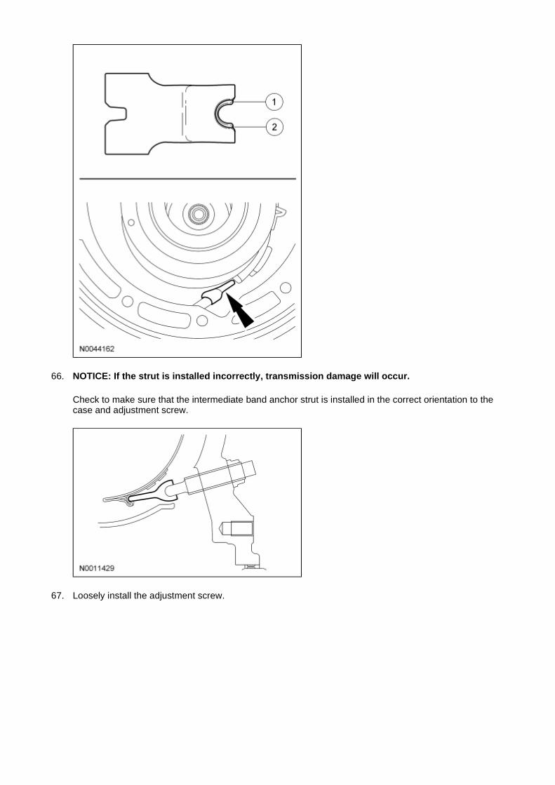
66. NOTICE: If the strut is installed incorrectly, transmission damage will occur.
Check to make sure that the intermediate band anchor strut is installed in the correct orientation to the case and adjustment screw.
67. Loosely install the adjustment screw.
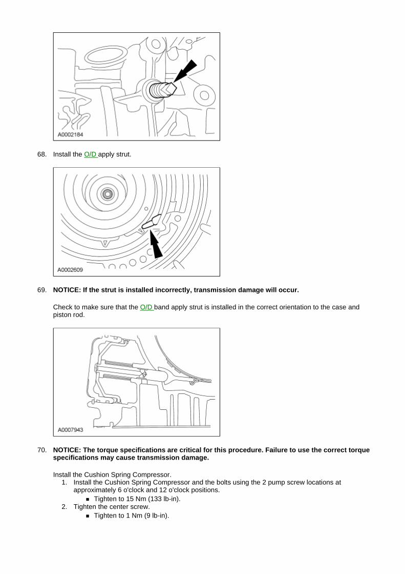
68. Install the O/D apply strut.
69. NOTICE: If the strut is installed incorrectly, transmission damage will occur.
Check to make sure that the O/D band apply strut is installed in the correct orientation to the case and piston rod.
70. NOTICE: The torque specifications are critical for this procedure. Failure to use the correct torque specifications may cause transmission damage.
Install the Cushion Spring Compressor. 1. Install the Cushion Spring Compressor and the bolts using the 2 pump screw locations at
approximately 6 o'clock and 12 o'clock positions. � Tighten to 15 Nm (133 lb-in).
2. Tighten the center screw. � Tighten to 1 Nm (9 lb-in).
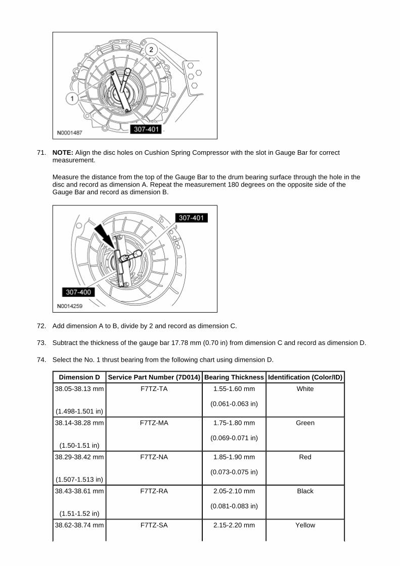
71. NOTE: Align the disc holes on Cushion Spring Compressor with the slot in Gauge Bar for correct measurement.
Measure the distance from the top of the Gauge Bar to the drum bearing surface through the hole in the disc and record as dimension A. Repeat the measurement 180 degrees on the opposite side of the Gauge Bar and record as dimension B.
72. Add dimension A to B, divide by 2 and record as dimension C.
73. Subtract the thickness of the gauge bar 17.78 mm (0.70 in) from dimension C and record as dimension D.
74. Select the No. 1 thrust bearing from the following chart using dimension D.
Dimension D Service Part Number (7D014) Bearing Thickness Identification (Color/ID)
38.05-38.13 mm
(1.498-1.501 in)
F7TZ-TA 1.55-1.60 mm
(0.061-0.063 in)
White
38.14-38.28 mm
(1.50-1.51 in)
F7TZ-MA 1.75-1.80 mm
(0.069-0.071 in)
Green
38.29-38.42 mm
(1.507-1.513 in)
F7TZ-NA 1.85-1.90 mm
(0.073-0.075 in)
Red
38.43-38.61 mm
(1.51-1.52 in)
F7TZ-RA 2.05-2.10 mm
(0.081-0.083 in)
Black
38.62-38.74 mm
F7TZ-SA 2.15-2.20 mm
Yellow
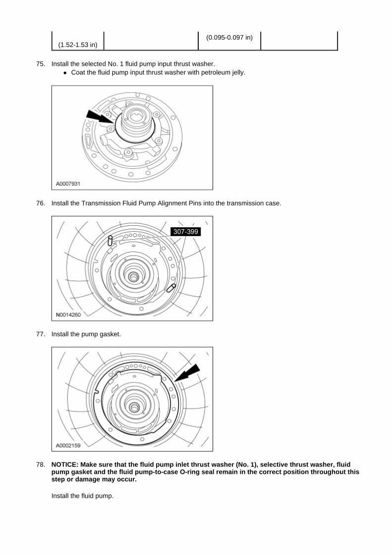
75. Install the selected No. 1 fluid pump input thrust washer.
� Coat the fluid pump input thrust washer with petroleum jelly.
76. Install the Transmission Fluid Pump Alignment Pins into the transmission case.
77. Install the pump gasket.
78. NOTICE: Make sure that the fluid pump inlet thrust washer (No. 1), selective thrust washer, fluid pump gasket and the fluid pump-to-case O-ring seal remain in the correct position throughout this step or damage may occur.
Install the fluid pump.
(1.52-1.53 in)
(0.095-0.097 in)
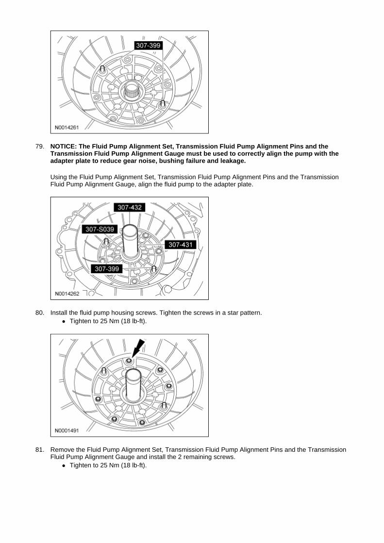
79. NOTICE: The Fluid Pump Alignment Set, Transmission Fluid Pump Alignment Pins and the Transmission Fluid Pump Alignment Gauge must be used to correctly align the pump with the adapter plate to reduce gear noise, bushing failure and leakage.
Using the Fluid Pump Alignment Set, Transmission Fluid Pump Alignment Pins and the Transmission Fluid Pump Alignment Gauge, align the fluid pump to the adapter plate.
80. Install the fluid pump housing screws. Tighten the screws in a star pattern. � Tighten to 25 Nm (18 lb-ft).
81. Remove the Fluid Pump Alignment Set, Transmission Fluid Pump Alignment Pins and the Transmission Fluid Pump Alignment Gauge and install the 2 remaining screws.
� Tighten to 25 Nm (18 lb-ft).
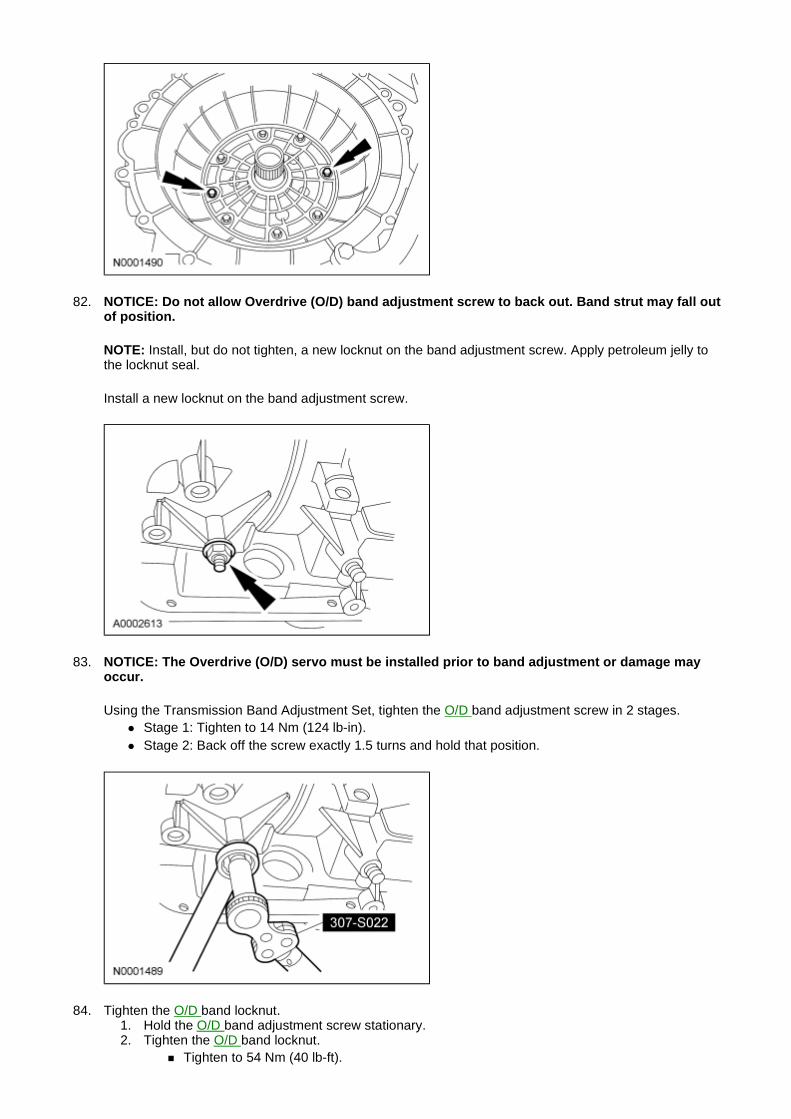
82. NOTICE: Do not allow Overdrive (O/D) band adjustment screw to back out. Band strut may fall out of position.
NOTE: Install, but do not tighten, a new locknut on the band adjustment screw. Apply petroleum jelly to the locknut seal.
Install a new locknut on the band adjustment screw.
83. NOTICE: The Overdrive (O/D) servo must be installed prior to band adjustment or damage may occur.
Using the Transmission Band Adjustment Set, tighten the O/D band adjustment screw in 2 stages. � Stage 1: Tighten to 14 Nm (124 lb-in). � Stage 2: Back off the screw exactly 1.5 turns and hold that position.
84. Tighten the O/D band locknut. 1. Hold the O/D band adjustment screw stationary. 2. Tighten the O/D band locknut.
� Tighten to 54 Nm (40 lb-ft).
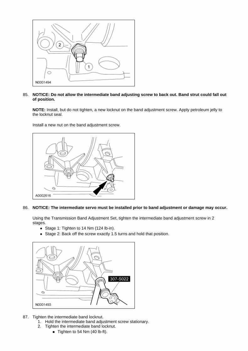
85. NOTICE: Do not allow the intermediate band adjusting screw to back out. Band strut could fall out of position.
NOTE: Install, but do not tighten, a new locknut on the band adjustment screw. Apply petroleum jelly to the locknut seal.
Install a new nut on the band adjustment screw.
86. NOTICE: The intermediate servo must be installed prior to band adjustment or damage may occur.
Using the Transmission Band Adjustment Set, tighten the intermediate band adjustment screw in 2 stages.
� Stage 1: Tighten to 14 Nm (124 lb-in). � Stage 2: Back off the screw exactly 1.5 turns and hold that position.
87. Tighten the intermediate band locknut. 1. Hold the intermediate band adjustment screw stationary. 2. Tighten the intermediate band locknut.
� Tighten to 54 Nm (40 lb-ft).
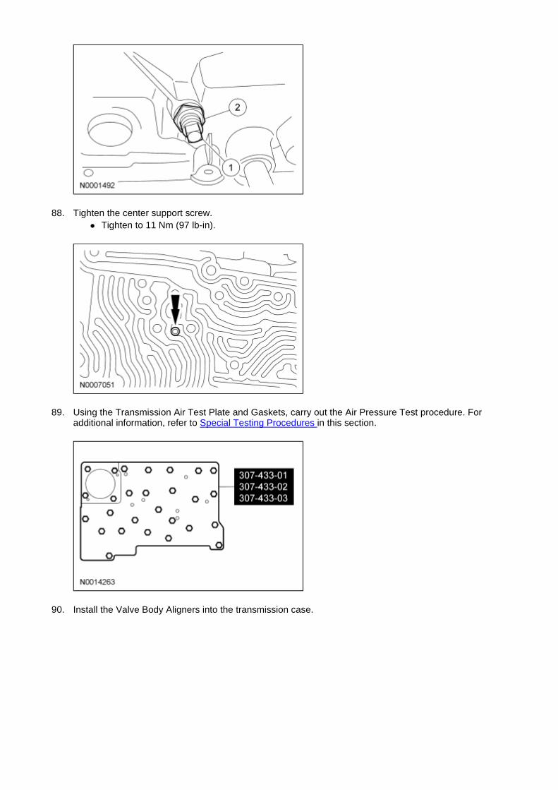
88. Tighten the center support screw. � Tighten to 11 Nm (97 lb-in).
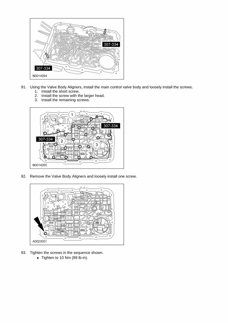
89. Using the Transmission Air Test Plate and Gaskets, carry out the Air Pressure Test procedure. For additional information, refer to Special Testing Procedures in this section.
90. Install the Valve Body Aligners into the transmission case.
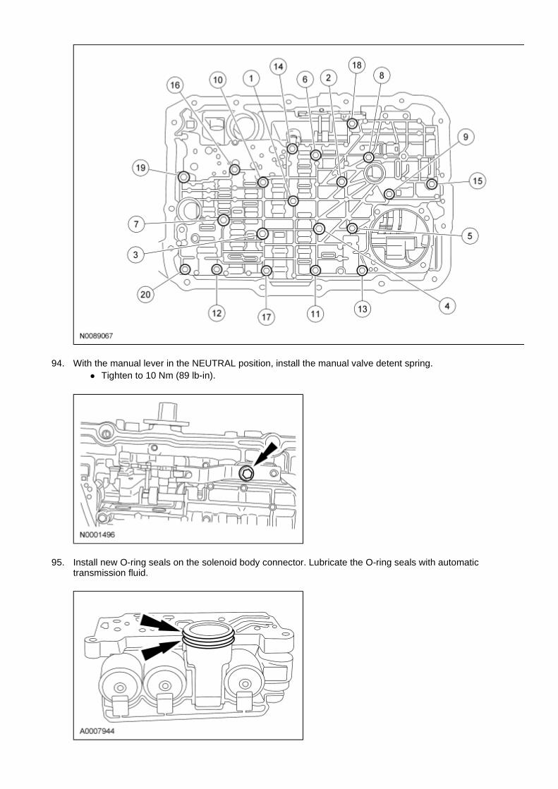
91. Using the Valve Body Aligners, install the main control valve body and loosely install the screws. 1. Install the short screw. 2. Install the screw with the larger head. 3. Install the remaining screws.
92. Remove the Valve Body Aligners and loosely install one screw.
93. Tighten the screws in the sequence shown. � Tighten to 10 Nm (89 lb-in).
94. With the manual lever in the NEUTRAL position, install the manual valve detent spring. � Tighten to 10 Nm (89 lb-in).
95. Install new O-ring seals on the solenoid body connector. Lubricate the O-ring seals with automatic transmission fluid.
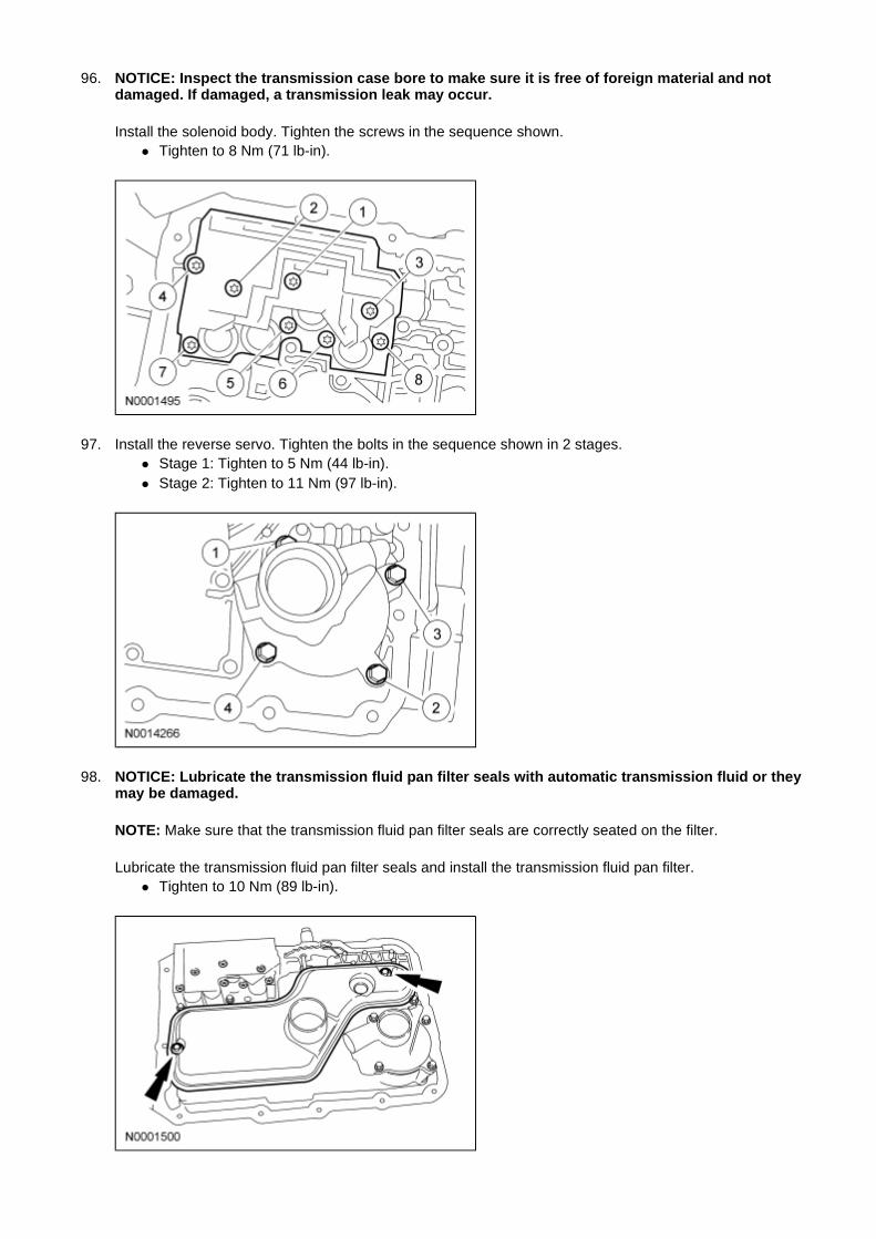
96. NOTICE: Inspect the transmission case bore to make sure it is free of foreign material and not damaged. If damaged, a transmission leak may occur.
Install the solenoid body. Tighten the screws in the sequence shown. � Tighten to 8 Nm (71 lb-in).
97. Install the reverse servo. Tighten the bolts in the sequence shown in 2 stages. � Stage 1: Tighten to 5 Nm (44 lb-in). � Stage 2: Tighten to 11 Nm (97 lb-in).
98. NOTICE: Lubricate the transmission fluid pan filter seals with automatic transmission fluid or they may be damaged.
NOTE: Make sure that the transmission fluid pan filter seals are correctly seated on the filter.
Lubricate the transmission fluid pan filter seals and install the transmission fluid pan filter. � Tighten to 10 Nm (89 lb-in).
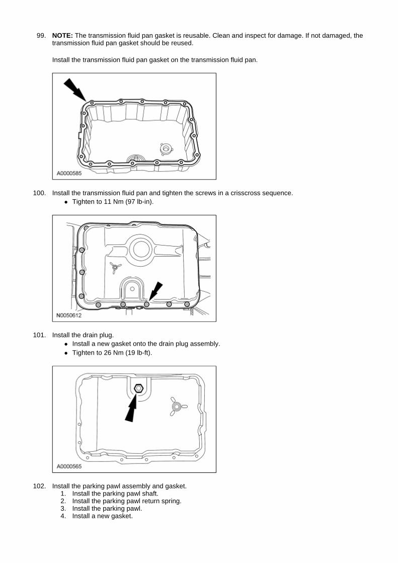
99. NOTE: The transmission fluid pan gasket is reusable. Clean and inspect for damage. If not damaged, the transmission fluid pan gasket should be reused.
Install the transmission fluid pan gasket on the transmission fluid pan.
100. Install the transmission fluid pan and tighten the screws in a crisscross sequence. � Tighten to 11 Nm (97 lb-in).
101. Install the drain plug. � Install a new gasket onto the drain plug assembly. � Tighten to 26 Nm (19 lb-ft).
102. Install the parking pawl assembly and gasket. 1. Install the parking pawl shaft. 2. Install the parking pawl return spring. 3. Install the parking pawl. 4. Install a new gasket.
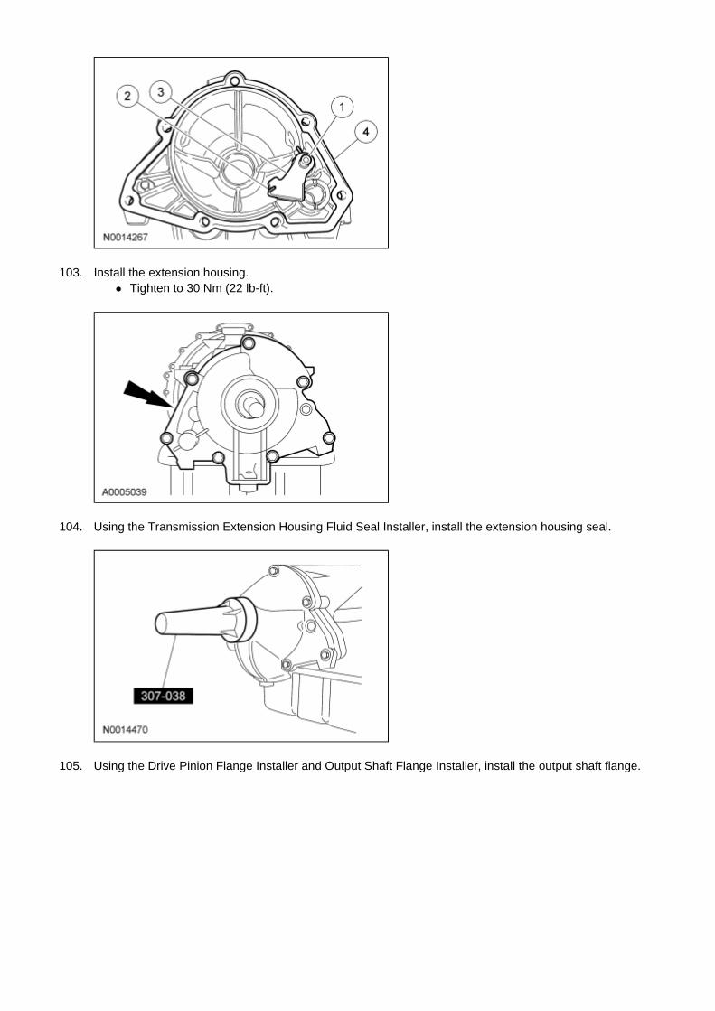
103. Install the extension housing. � Tighten to 30 Nm (22 lb-ft).
104. Using the Transmission Extension Housing Fluid Seal Installer, install the extension housing seal.
105. Using the Drive Pinion Flange Installer and Output Shaft Flange Installer, install the output shaft flange.
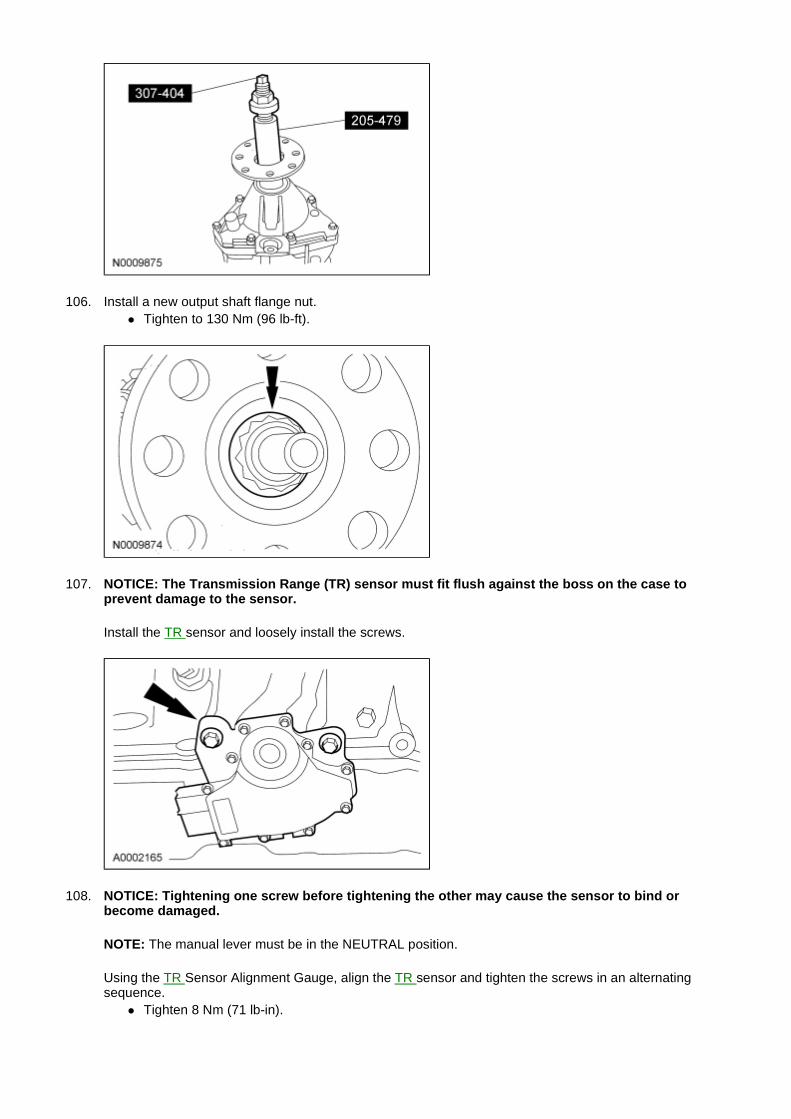
106. Install a new output shaft flange nut. � Tighten to 130 Nm (96 lb-ft).
107. NOTICE: The Transmission Range (TR) sensor must fit flush against the boss on the case to prevent damage to the sensor.
Install the TR sensor and loosely install the screws.
108. NOTICE: Tightening one screw before tightening the other may cause the sensor to bind or become damaged.
NOTE: The manual lever must be in the NEUTRAL position.
Using the TR Sensor Alignment Gauge, align the TR sensor and tighten the screws in an alternating sequence.
� Tighten 8 Nm (71 lb-in).
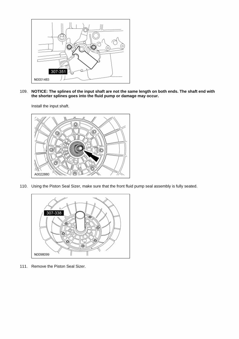
109. NOTICE: The splines of the input shaft are not the same length on both ends. The shaft end with the shorter splines goes into the fluid pump or damage may occur.
Install the input shaft.
110. Using the Piston Seal Sizer, make sure that the front fluid pump seal assembly is fully seated.
111. Remove the Piston Seal Sizer.
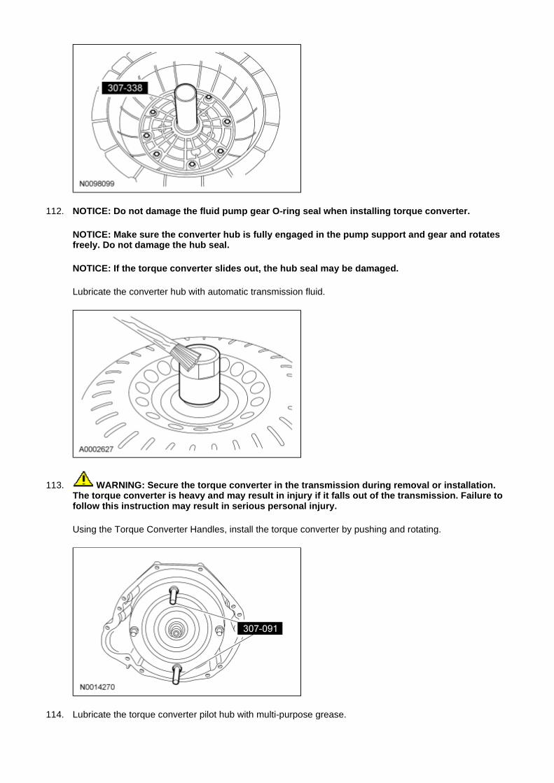
112. NOTICE: Do not damage the fluid pump gear O-ring seal when installing torque converter.
NOTICE: Make sure the converter hub is fully engaged in the pump support and gear and rotates freely. Do not damage the hub seal.
NOTICE: If the torque converter slides out, the hub seal may be damaged.
Lubricate the converter hub with automatic transmission fluid.
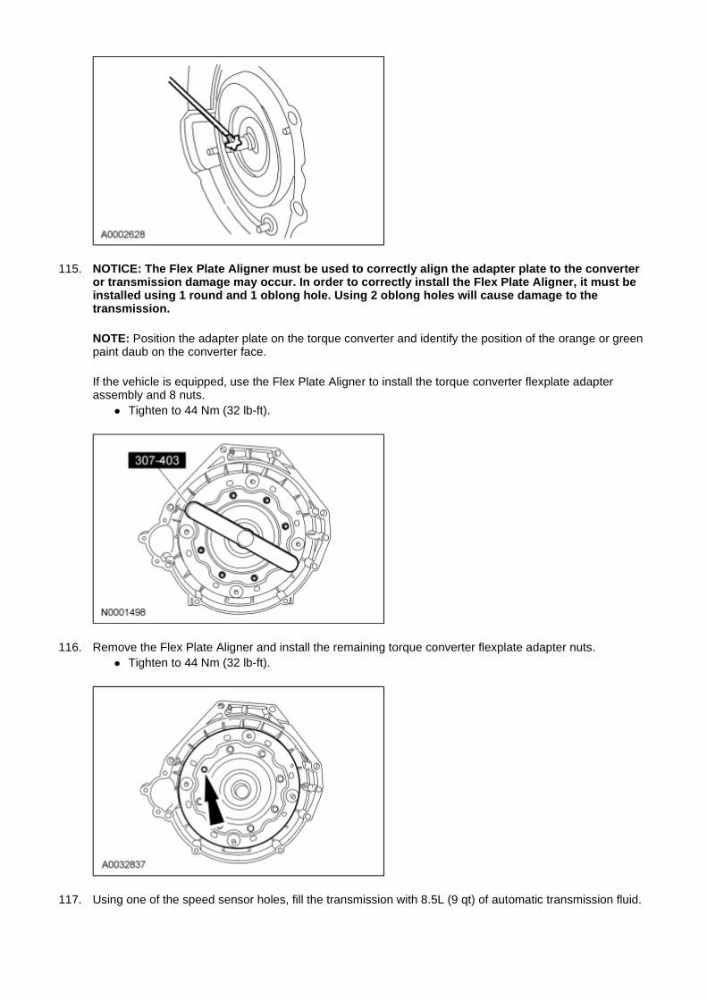
113. WARNING: Secure the torque converter in the transmission during removal or installation. The torque converter is heavy and may result in injury if it falls out of the transmission. Failure to follow this instruction may result in serious personal injury.
Using the Torque Converter Handles, install the torque converter by pushing and rotating.
114. Lubricate the torque converter pilot hub with multi-purpose grease.
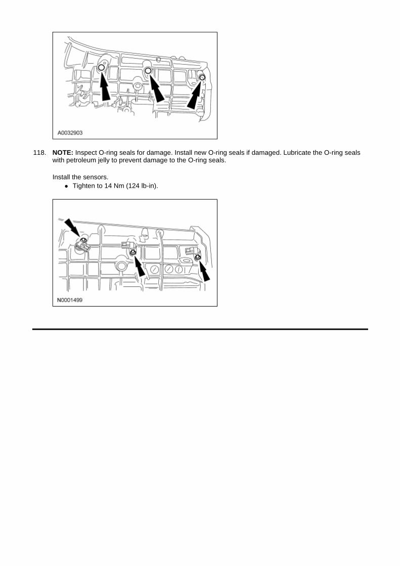
115. NOTICE: The Flex Plate Aligner must be used to correctly align the adapter plate to the converter or transmission damage may occur. In order to correctly install the Flex Plate Aligner, it must be installed using 1 round and 1 oblong hole. Using 2 oblong holes will cause damage to the transmission.
NOTE: Position the adapter plate on the torque converter and identify the position of the orange or green paint daub on the converter face.
If the vehicle is equipped, use the Flex Plate Aligner to install the torque converter flexplate adapter assembly and 8 nuts.
� Tighten to 44 Nm (32 lb-ft).
116. Remove the Flex Plate Aligner and install the remaining torque converter flexplate adapter nuts. � Tighten to 44 Nm (32 lb-ft).
117. Using one of the speed sensor holes, fill the transmission with 8.5L (9 qt) of automatic transmission fluid.
118. NOTE: Inspect O-ring seals for damage. Install new O-ring seals if damaged. Lubricate the O-ring seals with petroleum jelly to prevent damage to the O-ring seals.
Install the sensors. � Tighten to 14 Nm (124 lb-in).

![U660E AUTOMATIC TRANSMISSION / TRANSAXLE: … · u660e automatic transmission / transaxle: automatic transaxle fluid: adjustment; 2013 my camry [12/2012 -] 1. precautions and work](https://static.fdocuments.in/doc/165x107/5adfe3927f8b9ac0428cc9f3/u660e-automatic-transmission-transaxle-automatic-transmission-transaxle.jpg)


![Automatic Transaxle (Service) [Gf4ax-El]](https://static.fdocuments.in/doc/165x107/55cf8547550346484b8c4943/automatic-transaxle-service-gf4ax-el.jpg)