AUTOMATIC TRANSAXLE SYSTEM - Automotriz En...
439
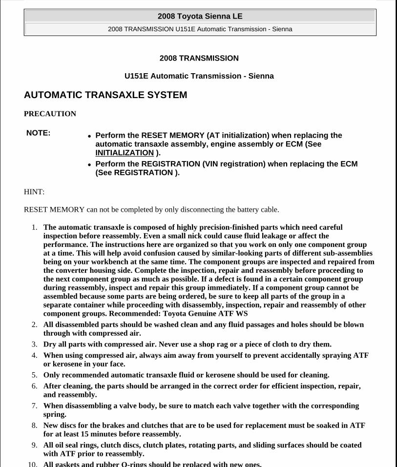
2008 TRANSMISSION U151E Automatic Transmission - Sienna AUTOMATIC TRANSAXLE SYSTEM PRECAUTION HINT: RESET MEMORY can not be completed by only disconnecting the battery cable. 1. The automatic transaxle is composed of highly precision-finished parts which need careful inspection before reassembly. Even a small nick could cause fluid leakage or affect the performance. The instructions here are organized so that you work on only one component group at a time. This will help avoid confusion caused by similar-looking parts of different sub-assemblies being on your workbench at the same time. The component groups are inspected and repaired from the converter housing side. Complete the inspection, repair and reassembly before proceeding to the next component group as much as possible. If a defect is found in a certain component group during reassembly, inspect and repair this group immediately. If a component group cannot be assembled because some parts are being ordered, be sure to keep all parts of the group in a separate container while proceeding with disassembly, inspection, repair and reassembly of other component groups. Recommended: Toyota Genuine ATF WS 2. All disassembled parts should be washed clean and any fluid passages and holes should be blown through with compressed air. 3. Dry all parts with compressed air. Never use a shop rag or a piece of cloth to dry them. 4. When using compressed air, always aim away from yourself to prevent accidentally spraying ATF or kerosene in your face. 5. Only recommended automatic transaxle fluid or kerosene should be used for cleaning. 6. After cleaning, the parts should be arranged in the correct order for efficient inspection, repair, and reassembly. 7. When disassembling a valve body, be sure to match each valve together with the corresponding spring. 8. New discs for the brakes and clutches that are to be used for replacement must be soaked in ATF for at least 15 minutes before reassembly. 9. All oil seal rings, clutch discs, clutch plates, rotating parts, and sliding surfaces should be coated with ATF prior to reassembly. 10. All gaskets and rubber O-rings should be replaced with new ones. NOTE: Perform the RESET MEMORY (AT initialization) when replacing the automatic transaxle assembly, engine assembly or ECM (See INITIALIZATION ). Perform the REGISTRATION (VIN registration) when replacing the ECM (See REGISTRATION ). 2008 Toyota Sienna LE 2008 TRANSMISSION U151E Automatic Transmission - Sienna
-
Upload
nguyenkhue -
Category
Documents
-
view
225 -
download
1
Transcript of AUTOMATIC TRANSAXLE SYSTEM - Automotriz En...
2008 TRANSMISSION
U151E Automatic Transmission - Sienna
AUTOMATIC TRANSAXLE SYSTEM
PRECAUTION
HINT:
RESET MEMORY can not be completed by only disconnecting the battery cable.
1. The automatic transaxle is composed of highly precision-finished parts which need careful inspection before reassembly. Even a small nick could cause fluid leakage or affect the performance. The instructions here are organized so that you work on only one component group at a time. This will help avoid confusion caused by similar-looking parts of different sub-assemblies being on your workbench at the same time. The component groups are inspected and repaired from the converter housing side. Complete the inspection, repair and reassembly before proceeding to the next component group as much as possible. If a defect is found in a certain component group during reassembly, inspect and repair this group immediately. If a component group cannot be assembled because some parts are being ordered, be sure to keep all parts of the group in a separate container while proceeding with disassembly, inspection, repair and reassembly of other component groups. Recommended: Toyota Genuine ATF WS
2. All disassembled parts should be washed clean and any fluid passages and holes should be blown through with compressed air.
3. Dry all parts with compressed air. Never use a shop rag or a piece of cloth to dry them.
4. When using compressed air, always aim away from yourself to prevent accidentally spraying ATF or kerosene in your face.
5. Only recommended automatic transaxle fluid or kerosene should be used for cleaning.
6. After cleaning, the parts should be arranged in the correct order for efficient inspection, repair, and reassembly.
7. When disassembling a valve body, be sure to match each valve together with the corresponding spring.
8. New discs for the brakes and clutches that are to be used for replacement must be soaked in ATF for at least 15 minutes before reassembly.
9. All oil seal rings, clutch discs, clutch plates, rotating parts, and sliding surfaces should be coated with ATF prior to reassembly.
10. All gaskets and rubber O-rings should be replaced with new ones.
NOTE: Perform the RESET MEMORY (AT initialization) when replacing the automatic transaxle assembly, engine assembly or ECM (See INITIALIZATION ).
Perform the REGISTRATION (VIN registration) when replacing the ECM (See REGISTRATION ).
2008 Toyota Sienna LE
2008 TRANSMISSION U151E Automatic Transmission - Sienna
2008 Toyota Sienna LE
2008 TRANSMISSION U151E Automatic Transmission - Sienna
Microsoft
Wednesday, August 12, 2009 2:03:22 PM Page 1 © 2005 Mitchell Repair Information Company, LLC.
Microsoft
Wednesday, August 12, 2009 2:03:36 PM Page 1 © 2005 Mitchell Repair Information Company, LLC.

11. Do not apply adhesive cements to gaskets and similar parts.
12. Make sure that the ends of a snap ring are not aligned with one of the cutouts and are installed in the groove correctly.
13. When replacing a worn bushing, the sub-assembly containing the bushing must also be replaced.
14. Check thrust bearings and races for wear or damage. Replace them as necessary.
15. When working with FIPG material, you must observe the following:
Using a razor blade and a gasket scraper, remove all the old packing (FIPG) material from the gasket surface.
Thoroughly clean all components to remove any loose material.
Clean both sealing surfaces with a non-residue solvent.
Parts must be reassembled within 10 minutes of application. Otherwise, the packing (FIPG) material must be removed and reapplied.
DEFINITION OF TERMS
DEFINITION OF TERMS Term Definition
Monitor description Description of what the ECM monitors and how it detects malfunctions (monitoring purpose and its details).
Related DTCs Diagnostic code
Typical enabling condition
Preconditions that allow the ECM to detect malfunctions. With all preconditions satisfied, the ECM sets the DTC when the monitored value(s) exceeds the malfunction threshold(s).
Sequence of operation
The priority order that is applied to monitoring, if multiple sensors and components are used to detect the malfunction. While another sensor is being monitored, the next sensor or component will not be monitored until the previous monitoring has concluded.
Required sensor/components The sensors and components that are used by the ECM to detect malfunctions.
Frequency of operation
The number of times that the ECM checks for malfunctions per driving cycle. "Once per driving cycle" means that the ECM detects malfunction only one time during a single driving cycle. "Continuous" means that the ECM detects malfunction every time when enabling condition is met.
Duration The minimum time that the ECM must sense a continuous deviation in the monitored value(s)
2008 Toyota Sienna LE
2008 TRANSMISSION U151E Automatic Transmission - Sienna
Microsoft
Wednesday, August 12, 2009 2:03:22 PM Page 2 © 2005 Mitchell Repair Information Company, LLC.

PARTS LOCATION
before setting a DTC. This timing begins after the "typical enabling conditions" are met.
Malfunction thresholds Beyond this value, the ECM will conclude that there is a malfunction and set a DTC.
MIL operation
MIL illumination timing after a defect is detected. "Immediately" means that the ECM illuminates MIL the instant the ECM determines that there is a malfunction. "2 driving cycle" means that the ECM illuminates MIL if the same malfunction is detected again in the 2nd driving cycle.
Component operating range
Normal operation range of sensors and solenoids under normal driving conditions. Use these ranges as a reference. They cannot be used to judge if a sensor or solenoid is defective or not.
2008 Toyota Sienna LE
2008 TRANSMISSION U151E Automatic Transmission - Sienna
Microsoft
Wednesday, August 12, 2009 2:03:22 PM Page 3 © 2005 Mitchell Repair Information Company, LLC.

Fig. 1: Identifying Automatic Transmission System Components Location Courtesy of TOYOTA MOTOR SALES, U.S.A., INC.
SYSTEM DIAGRAM
The configuration of the electronic control system in the U151E automatic transaxles is as shown in the following chart.
2008 Toyota Sienna LE
2008 TRANSMISSION U151E Automatic Transmission - Sienna
Microsoft
Wednesday, August 12, 2009 2:03:22 PM Page 4 © 2005 Mitchell Repair Information Company, LLC.

Fig. 2: Automatic Transmission System Diagram Courtesy of TOYOTA MOTOR SALES, U.S.A., INC.
SYSTEM DESCRIPTION
1. SYSTEM DESCRIPTION
a. The ECT (Electronic controlled automatic transmission/transaxle) is an automatic transmission/transaxle that electronically controls shift timing using the ECM. The ECM detects electrical signals that indicate engine and driving conditions, and controls the shift point, based on
2008 Toyota Sienna LE
2008 TRANSMISSION U151E Automatic Transmission - Sienna
Microsoft
Wednesday, August 12, 2009 2:03:22 PM Page 5 © 2005 Mitchell Repair Information Company, LLC.

driver habits and road conditions. As a result, fuel efficiency and power transmission performance are improved.
Shift shock has been reduced by controlling the engine and transmission simultaneously. In addition, the ECT has features such as follows:
Diagnostic function.
Fail-safe function when a malfunction occurs.
HOW TO PROCEED WITH TROUBLESHOOTING
HINT:
The ECM of this system is connected to the CAN and multiplex communication system. Therefore, before starting troubleshooting, make sure to check that there is no trouble in the CAN and multiplex communication systems.
Techstream can be used at steps 3, 4, 6, and 9.
1. Vehicle Brought to Workshop
2. Customer Problem Analysis
3. Connect Techstream to DLC3
4. Check and Clear DTCs and Freeze Frame Data
HINT:
*See DTC CHECK / CLEAR ).
5. Visual Inspection
6. Setting the Check Mode Diagnosis
HINT:
(See CHECK MODE PROCEDURE ).
7. Problem Symptom Confirmation
HINT:
(See HOW TO PROCEED WITH TROUBLESHOOTING ).
Symptom does not occur: Go to step 8
Symptom occurs: Go to step 9
8. Symptom Simulation
2008 Toyota Sienna LE
2008 TRANSMISSION U151E Automatic Transmission - Sienna
Microsoft
Wednesday, August 12, 2009 2:03:22 PM Page 6 © 2005 Mitchell Repair Information Company, LLC.
HINT:
(See HOW TO PROCEED WITH TROUBLESHOOTING ).
9. DTC Check
HINT:
(See DTC CHECK / CLEAR ).
DTC is not output: Go to step 10
DTC is output: Go to step 17
10. Basic Inspection
HINT:
(See INSPECTION , ON-VEHICLE INSPECTION and ADJUSTMENT ).
NG: Go to step 19
OK: Go to Next Step
11. Mechanical System Test
HINT:
(See MECHANICAL SYSTEM TESTS ).
NG: Go to step 16
OK: Go to Next Step
12. Hydraulic Test
HINT:
(See HYDRAULIC TEST ).
NG: Go to step 16
OK: Go to Next Step
13. Manual Shifting Test
2008 Toyota Sienna LE
2008 TRANSMISSION U151E Automatic Transmission - Sienna
Microsoft
Wednesday, August 12, 2009 2:03:22 PM Page 7 © 2005 Mitchell Repair Information Company, LLC.

HINT:
(See MANUAL SHIFTING TEST ).
NG: Go to step 15
OK: Go to Next Step
14. Problem Symptoms Table Chapter 1
HINT:
(See PROBLEM SYMPTOMS TABLE ).
NG: Go to step 18
OK: Go to Next Step
15. Problem Symptoms Table Chapter 2
HINT:
(See PROBLEM SYMPTOMS TABLE ).
16. Part Inspection
Go to step 19
17. DTC Chart
HINT:
(See DIAGNOSTIC TROUBLE CODE CHART ).
18. Circuit Inspection
19. Repair or Replace
20. Confirmation Test
NEXT: End
ROAD TEST
1. PROBLEM SYMPTOM CONFIRMATION
a. Based on the result of the customer problem analysis, try to reproduce the symptoms. If the problem is that the transaxle does not shift up, shift down, or the shift point is too high or too low, conduct the following road test referring to the automatic shift schedule and simulate the problem
2008 Toyota Sienna LE
2008 TRANSMISSION U151E Automatic Transmission - Sienna
Microsoft
Wednesday, August 12, 2009 2:03:22 PM Page 8 © 2005 Mitchell Repair Information Company, LLC.

symptoms.
2. ROAD TEST
a. D position test:
Shift into the D position and fully depress the accelerator pedal and check the following points.
1. Check up-shift operation.
Check that 1 --> 2, 2 --> 3, 3 --> 4 and 4 --> 5th upshifts take place, and that the shift points conform to the automatic shift schedule (See SERVICE DATA ).
HINT:
5th Gear Up-shift Prohibition Control
Engine coolant temperature is 55°C (131°F) or less and vehicle speed is at 80 km/h (176 mph) or less.
ATF temperature is -2°C (28°F) or less.
4th Gear Up-shift Prohibition Control
Coolant temperature is 47°C (117°F) or less and vehicle speed is at 55 km/h (34 mph) or less.
5th and 4th Gear Lock-up Prohibition Control
Brake pedal is depressed.
Accelerator pedal is released.
Coolant temperature is 60°C (140°F) or less.
2. Check for shift shock and slip.
Check for shock and slip at the 1 --> 2, 2 --> 3, 3 --> 4 and 4 --> 5th up-shifts.
3. Check for abnormal noise and vibration.
Drive in the D position lock-up or 5th gear, and check for abnormal noises and vibration.
HINT:
The check for the cause of abnormal noise and vibration must be done very thoroughly as it could also be due to loss of balance in the differential, torque converter clutch, etc.
NOTE: Perform the test at the ATF temperature 50 to 80°C (122 to 176°F) in the normal operation.
2008 Toyota Sienna LE
2008 TRANSMISSION U151E Automatic Transmission - Sienna
Microsoft
Wednesday, August 12, 2009 2:03:22 PM Page 9 © 2005 Mitchell Repair Information Company, LLC.

4. Check kick-down operation.
Check that the possible kick-down vehicle speed limits for 2nd to 1st, 3rd to 2nd, 4th to 3rd, 5th to 4th kick-downs conform to those indicated on the automatic shift schedule while driving through all gears with the shift lever in the D position (See SERVICE DATA ).
5. Cheek abnormal shock and slip at kick-down.
6. Check the lock-up mechanism.
Drive in D position (5th gear), at a steady speed (lock-up ON).
Lightly depress the accelerator pedal and check that the engine speed does not change abruptly.
HINT:
There is no lock-up in the 1st and 2nd gear.
4th lock-up operates while uphill-downhill control is active in D position.
3rd lock-up operates while uphill-downhill control is active in D position.
ATF temperature is 120°C (248°F) or more.
If there is a big jump in engine speed, there is no lock-up.
b. 4 (O/D OFF) position test:
Shift into the 4 position and fully depress the accelerator pedal and check the following points.
1. Check up-shift operation.
Check that the 1 --> 2, 2 --> 3 and 3 --> 4 up-shift take place and that the shift point conforms to the automatic shift schedule (See SERVICE DATA ).
HINT:
There is no 5th up-shift in the 4 position.
2. Check engine braking.
While driving in the 4 position and 4th gear, release the accelerator pedal and check the engine braking effect.
3. Check for abnormal noise during acceleration and deceleration, and for shock at up-shift and down-shift.
c. 3 position test:
Shift into the 3 position and fully depress the accelerator pedal and check the following points.
1. Check up-shift operation.
2008 Toyota Sienna LE
2008 TRANSMISSION U151E Automatic Transmission - Sienna
Microsoft
Wednesday, August 12, 2009 2:03:22 PM Page 10 © 2005 Mitchell Repair Information Company, LLC.

Check that the 1 --> 2 and 2 --> 3 up-shift take place and that the shift point conforms to the automatic shift schedule (See SERVICE DATA ).
HINT:
There is no 4th up-shift and lock-up in the 3 position.
2. Check engine braking.
While running in the 3 position and 3rd gear, release the accelerator pedal and check the engine braking effect.
3. Check for abnormal noise during acceleration and deceleration, and for shock at up-shift and down-shift.
d. 2 position test:
Shift into the 2 position and fully depress the accelerator pedal and check the following points.
1. Check up-shift operation.
Check that the 1 --> 2 up-shift takes place and that the shift point conforms to the automatic shift schedule (See SERVICE DATA ).
HINT:
There is no 3rd up-shift and lock-up in the 2 position.
2. Check engine braking.
While running in the 2 position and 2nd gear, release the accelerator pedal and check the engine braking effect.
3. Check for abnormal noise during acceleration and deceleration, and for shock at up-shift and down-shift.
e. L position test:
Shift into the L position and fully depress the accelerator pedal and check the following points.
1. Check no up-shift.
While running in the L position, check that there is no up-shift to 2nd gear.
HINT:
There is no lock-up in the L position.
2008 Toyota Sienna LE
2008 TRANSMISSION U151E Automatic Transmission - Sienna
Microsoft
Wednesday, August 12, 2009 2:03:22 PM Page 11 © 2005 Mitchell Repair Information Company, LLC.

2. Check engine braking.
While running in the L position, release the accelerator pedal and check the engine braking effect.
3. Check for abnormal noise during acceleration and deceleration.
f. R position test:
Shift into the R position and fully depress the accelerator pedal and check for slipping.
g. P position test:
Stop the vehicle on the grade (more than 5°) and after shifting into the P position, release the parking brake. Then, check that the parking lock pawl holds the vehicle in place.
h. Uphill/downhill control function test:
1. Check that the gear does not up-shift to the 4th or 5th gear while the vehicle is driving uphill.
2. Check that the gear automatically down-shifts from 5th to 4th or from the 4th to 3rd gear when brake is applied while the vehicle is driving downhill.
MECHANICAL SYSTEM TESTS
1. PERFORM MECHANICAL SYSTEM TESTS
a. Measure the stall speed.
The object of this test is to check the overall performance of the transaxle and engine by measuring the stall speeds in the D position.
1. Chock the 4 wheels.
2. Connect Techstream to the DLC3.
CAUTION: Before conducting this test ensure that the test area is free from people and obstruction.
NOTE: Driving test should be done on a paved road (a nonskid road).
Perform the test at the normal operating ATF (Automatic Transmission Fluid) temperature 50 to 80°C (122 to 176°F).
Do not continuously run this test for longer than 10 seconds.
To ensure safety, do this test in a wide, clear level area which provides good traction.
The stall test should always be carried out in pairs. One technician should observe the conditions of wheels or wheel stoppers outside the vehicle while the other is doing the test.
2008 Toyota Sienna LE
2008 TRANSMISSION U151E Automatic Transmission - Sienna
Microsoft
Wednesday, August 12, 2009 2:03:22 PM Page 12 © 2005 Mitchell Repair Information Company, LLC.

3. Fully apply the parking brake.
4. Keep your left foot pressed firmly on the brake pedal.
5. Start the engine.
6. Shift into the D position. Press all the way down on the accelerator pedal with your right foot.
7. Quickly read the stall speed at this time.
Stall speed: 2,300+-150 rpm
Evaluation:
EVALUATION CHART
b. Measure the time lag.
1. When the shift lever is shifted while the engine is idling, there will be a certain time lapse or lag before the shock can be felt. This is used for checking the condition of the clutch and brake.
Problem Possible cause
(a) Stall engine speed is low in D position
Engine power output may be insufficient
Stator one-way clutch not operating properly
HINT: If the value is less than the specified value by 600 rpm or more, the torque converter could be faulty.
(b) Stall engine speed is high in D position
Line pressure is too low
Forward clutch slipping
U/D (Underdrive) brake slipping
U/D (Underdrive) one-way clutch is not operating properly
No.1 one-way clutch not operating properly
Improper fluid level
NOTE: Perform the test at the normal operating ATF (Automatic Transmission Fluid) temperature: 50 to 80°C (122 to 176°F).
Be sure to allow 1 minute interval between tests.
Perform the test three times, and measure the time lags. Calculate the average value of the three time lags.
2008 Toyota Sienna LE
2008 TRANSMISSION U151E Automatic Transmission - Sienna
Microsoft
Wednesday, August 12, 2009 2:03:22 PM Page 13 © 2005 Mitchell Repair Information Company, LLC.

2. Connect Techstream to the DLC3.
3. Fully apply the parking brake.
4. Start and warm up the engine and check idle speed.
Idle speed: approx. 700 rpm (In N position and A/C OFF)
5. Shift the lever from N to D position. Using a stop watch, measure the time from when the lever is shifted until the shock is felt.
Time lag: N --> D less than 1.2 seconds
6. In the same way, measure the time lag for N --> R.
Time lag: N --> R less than 1.5 seconds
Evaluation (If N --> D or N --> R time lag is longer than the specified):
EVALUATION CHART
HYDRAULIC TEST
1. PERFORM HYDRAULIC TEST
a. Measure the line pressure.
When conducting stall test, do not continue more than 10 seconds.
Problem Possible cause
N --> D time lag is longer
Line pressure is too low
Forward clutch worn
No.1 one-way clutch is not operating properly
U/D (Underdrive) one-way clutch is not operating
U/D (Underdrive) brake worn
N --> R time lag is longer
Line pressure is too low
Reverse clutch worn
1st and reverse brake worn
U/D (Underdrive) brake worn
NOTE: Perform the test at the normal operating ATF (Automatic Transmission Fluid) temperature: 50 to 80°C (122 to 176°F).
The line pressure test should always be carried out in pairs.
2008 Toyota Sienna LE
2008 TRANSMISSION U151E Automatic Transmission - Sienna
Microsoft
Wednesday, August 12, 2009 2:03:22 PM Page 14 © 2005 Mitchell Repair Information Company, LLC.

1. Warm up the ATF (Automatic Transmission Fluid).
2. Lift the vehicle up.
3. Remove the engine under cover.
4. Connect Techstream to the DLC3.
5. Remove the test plug A on the transaxle case front left side and install the SST.
One technician should observe the conditions of wheels or wheel stoppers outside the vehicle while the other is performing the test.
Be careful to prevent SST hose from interfering with the exhaust pipe.
This Check must be conducted after checking and adjusting engine.
Perform under condition that A/C is OFF.
When conducting stall test, do not continue more than 10 seconds.
Fig. 3: Measuring Line Pressure Courtesy of TOYOTA MOTOR SALES, U.S.A., INC.
2008 Toyota Sienna LE
2008 TRANSMISSION U151E Automatic Transmission - Sienna
Microsoft
Wednesday, August 12, 2009 2:03:22 PM Page 15 © 2005 Mitchell Repair Information Company, LLC.

SST 09992-00095 (09992-00231, 09992-00271)
6. Start the engine.
7. Using Techstream, shift to D position and hold 3rd gear by active test, and measure the line pressure in idling.
Specified line pressure:
LINE PRESSURE SPECIFICATION
8. Turn the ignition switch off.
9. Disconnect the connector of the transmission wire.
HINT:
Disconnect the connector only when performing the D position stall test.
10. Start the engine.
11. Firmly depress the brake pedal, shift to the D position, depress the accelerator pedal all the way down and check the line pressure while the stall test is performed.
Specified line pressure:
LINE PRESSURE SPECIFICATION
12. Turn the ignition switch off.
13. Remove the SST, install the test plug A.
14. Remove the test plug B, install the SST and start engine.
NOTE: There is a difference in installation point between D position and R position.
Condition D position kPa (kgf / cm2 , psi)Idling 372 to 412 kPa (3.8 to 4.2 kgf/cm2 , 54 to 60
psi)
Condition D position kPa (kgf / cm2 , psi)Stall test 931 to 1,031 kPa (9.5 to 10.5 kgf/cm2 , 135
to 150 psi)
2008 Toyota Sienna LE
2008 TRANSMISSION U151E Automatic Transmission - Sienna
Microsoft
Wednesday, August 12, 2009 2:03:22 PM Page 16 © 2005 Mitchell Repair Information Company, LLC.

Fig. 4: Locating Transmission Wire Connector Courtesy of TOYOTA MOTOR SALES, U.S.A., INC.
SST 09992-00095 (09992-00231, 09992-00271)
15. Connect the transmission wire connector, depress the brake pedal firmly, shift to the R position and check that the line pressure while the engine is idling and during the stall test.
Specified line pressure:
LINE PRESSURE SPECIFICATION
16. Remove the SST, install the test plug B.
17. Clear the DTC.
Evaluation:
EVALUATION CHART
Condition R position kPa (kgf / cm2 , psi)Idling 672 to 742 kPa (6.9 to 7.6 kgf/cm2 , 97 to
108 psi)Stall test 1,768 to 1,968 kPa (18.0 to 20.1 kgf/cm2 ,
256 to 285 psi)
Problem Possible cause
2008 Toyota Sienna LE
2008 TRANSMISSION U151E Automatic Transmission - Sienna
Microsoft
Wednesday, August 12, 2009 2:03:22 PM Page 17 © 2005 Mitchell Repair Information Company, LLC.
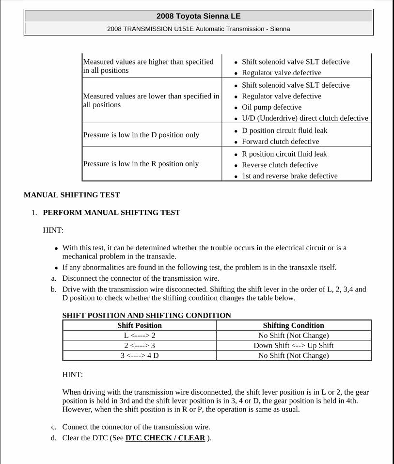
MANUAL SHIFTING TEST
1. PERFORM MANUAL SHIFTING TEST
HINT:
With this test, it can be determined whether the trouble occurs in the electrical circuit or is a mechanical problem in the transaxle.
If any abnormalities are found in the following test, the problem is in the transaxle itself.
a. Disconnect the connector of the transmission wire.
b. Drive with the transmission wire disconnected. Shifting the shift lever in the order of L, 2, 3,4 and D position to check whether the shifting condition changes the table below.
SHIFT POSITION AND SHIFTING CONDITION
HINT:
When driving with the transmission wire disconnected, the shift lever position is in L or 2, the gear position is held in 3rd and the shift lever position is in 3, 4 or D, the gear position is held in 4th. However, when the shift position is in R or P, the operation is same as usual.
c. Connect the connector of the transmission wire.
d. Clear the DTC (See DTC CHECK / CLEAR ).
Measured values are higher than specified in all positions
Shift solenoid valve SLT defective
Regulator valve defective
Measured values are lower than specified in all positions
Shift solenoid valve SLT defective
Regulator valve defective
Oil pump defective
U/D (Underdrive) direct clutch defective
Pressure is low in the D position only D position circuit fluid leak
Forward clutch defective
Pressure is low in the R position only R position circuit fluid leak
Reverse clutch defective
1st and reverse brake defective
Shift Position Shifting ConditionL <----> 2 No Shift (Not Change)2 <----> 3 Down Shift <--> Up Shift
3 <----> 4 D No Shift (Not Change)
2008 Toyota Sienna LE
2008 TRANSMISSION U151E Automatic Transmission - Sienna
Microsoft
Wednesday, August 12, 2009 2:03:22 PM Page 18 © 2005 Mitchell Repair Information Company, LLC.

Fig. 5: Locating Transmission Wire Connector Courtesy of TOYOTA MOTOR SALES, U.S.A., INC.
INITIALIZATION
1. RESET MEMORY
HINT:
The ECM memorizes the condition that the ECT controls the automatic transaxle assembly and engine assembly according to those characteristics. Therefore, when the automatic transaxle assembly, engine assembly, or ECM has been replaced, it is necessary to reset the memory so that the ECM can memorize the new information. Reset procedure is as follows.
a. Turn the engine switch off.
b. Connect Techstream to the DLC3.
c. Turn the ignition switch to the ON position and push the Techstream main switch on.
d. Enter the following menus: Powertrain / Engine and ECT / Utility / Reset Memory. Then, press "Next".
e. Perform the reset memory procedure from the main menu.
NOTE: Perform the RESET MEMORY (AT initialization) when replacing the automatic transaxle assembly, engine assembly or ECM.
The RESET MEMORY can be performed only with Techstream.
2008 Toyota Sienna LE
2008 TRANSMISSION U151E Automatic Transmission - Sienna
Microsoft
Wednesday, August 12, 2009 2:03:22 PM Page 19 © 2005 Mitchell Repair Information Company, LLC.

HINT:
The ECM is learned by performing the ROAD TEST.
MONITOR DRIVE PATTERN
1. MONITOR DRIVE PATTERN FOR ECT TEST
a. Perform this drive pattern as one method to simulate the detection conditions of the ECT malfunctions. (The DTCs may not be detected due the actual driving conditions. And some codes may not be detected through this drive pattern.)
HINT:
Preparation for driving
Warm up the engine sufficiently. (Engine coolant temperature is 60°C (140°F) or higher)
Drive the vehicle when the atmospheric temperature is -10°C (14°F) or higher. (Malfunction is not detected when the atmospheric temperature is less than -10°C
Driving note
Drive the vehicle through all gears.
Stop --> 1st --> 2nd --> 3rd --> 4th --> 5th --> 5th (lock-up ON).
Repeat the above driving pattern three times or more.
CAUTION: After performing the RESET MEMORY, be sure to perform the ROAD TEST described earlier.
NOTE: The monitor status can be checked using Techstream. When using Techstream, monitor status can be found in the "Powertrain / Engine anECT / Data List".
In the event that the drive pattern must be interrupted (possibly due to traffic conditions or other factors), the drive pattern can be resumed anin most cases, the monitor can be completed.
Perform this drive pattern on a level road as much as possible and stricobserve the posted speed limits and traffic laws while driving.
2008 Toyota Sienna LE
2008 TRANSMISSION U151E Automatic Transmission - Sienna
Microsoft
Wednesday, August 12, 2009 2:03:22 PM Page 20 © 2005 Mitchell Repair Information Company, LLC.

HINT:
*1: Drive at such a speed in the uppermost gear, to engage lock-up. The vehicle can be driven at a speed lower than that in the above diagram under the lock-up condition.
PROBLEM SYMPTOMS TABLE
HINT:
If a normal code is displayed during the diagnostic trouble code check although the trouble still occurs, check the electrical circuits for each symptom in the order given in the following charts.
The Matrix Chart is divided into 2 chapters.
When the circuit on which mark *1 is attached is a malfunction, DTC could be output.
Refer to the table below when the trouble cause is considered to be electrical. If the instruction PROCEED TO NEXT CIRCUIT INSPECTION SHOWN IN PROBLEM SYMPTOMS TABLE is given in the flowchart of each circuit, inspect the suspected areas in descending order for each symptom. If the trouble still occurs even though there are no abnormalities in the inspections listed for the symptoms, check and replace the ECM.
Fig. 6: Vehicle Speed Graph Courtesy of TOYOTA MOTOR SALES, U.S.A., INC.
NOTE: If necessary to drive the vehicle for approximately 30 minutes to detect DTC P0711 (ATF temperature sensor malfunction).
2008 Toyota Sienna LE
2008 TRANSMISSION U151E Automatic Transmission - Sienna
Microsoft
Wednesday, August 12, 2009 2:03:22 PM Page 21 © 2005 Mitchell Repair Information Company, LLC.

1. Chapter 1: Electronic Circuit Matrix Chart
PROBLEM SYMPTOMS TABLE Symptom Suspected Area See
No down-shift (A particular gear, from 1st to 4th gear, is not down-shifted)
ECM HOW TO TROUBLESHOOT ECU CONTROLLED SYSTEMS
No down-shift (5th -> 4th)
Transmission control switch (D <--> 4 position) circuit
DTC P0705 TRANSMISSION RANGE SENSOR CIRCUIT MALFUNCTION (PRNDL INPUT)
Shift solenoid valve S4 circuit *1 DTC P0982 SHIFT SOLENOID "D" CONTROL CIRCUIT LOW (SHIFT SOLENOID VALVE S4); DTC P0983 SHIFT SOLENOID "D" CONTROL CIRCUIT HIGH (SHIFT SOLENOID VALVE S4)
ECM HOW TO TROUBLESHOOT ECU CONTROLLED SYSTEMS
No up-shift (A particular gear, from 1st to 4th gear, is not up-shifted)
ECM HOW TO TROUBLESHOOT ECU CONTROLLED SYSTEMS
No up-shift (4th -> 5th)
Transmission control switch (D <--> 4 position) circuit
DTC P0705 TRANSMISSION RANGE SENSOR CIRCUIT MALFUNCTION (PRNDL INPUT)
Shift solenoid valve S4 circuit *1 DTC P0982 SHIFT SOLENOID "D" CONTROL CIRCUIT LOW (SHIFT SOLENOID VALVE S4); DTC P0983 SHIFT SOLENOID "D" CONTROL CIRCUIT HIGH (SHIFT SOLENOID VALVE S4)
ECM HOW TO TROUBLESHOOT ECU CONTROLLED SYSTEMS
No lock-up
Stop light switch circuit *1 DTC P0724 BRAKE SWITCH "B" CIRCUIT HIGH
Engine coolant temp, sensor circuit *1
DIAGNOSTIC TROUBLE CODE CHART
ECM HOW TO TROUBLESHOOT ECU CONTROLLED SYSTEMS
No lock-up off ECM HOW TO TROUBLESHOOT ECU CONTROLLED SYSTEMS
Throttle position sensor circuit *1 DIAGNOSTIC TROUBLE CODE
2008 Toyota Sienna LE
2008 TRANSMISSION U151E Automatic Transmission - Sienna
Microsoft
Wednesday, August 12, 2009 2:03:22 PM Page 22 © 2005 Mitchell Repair Information Company, LLC.

Shift point too high or too lowCHART
ECM HOW TO TROUBLESHOOT ECU CONTROLLED SYSTEMS
Up-shift to 5th from 4th while shift lever is in 4 position
Transmission control switch (D <--> 4 position) circuit
DTC P0705 TRANSMISSION RANGE SENSOR CIRCUIT MALFUNCTION (PRNDL INPUT)
ECM HOW TO TROUBLESHOOT ECU CONTROLLED SYSTEMS
Up-shift to 5th from 4th while engine is cold
Engine coolant temp, sensor circuit *1
DIAGNOSTIC TROUBLE CODE CHART
ECM HOW TO TROUBLESHOOT ECU CONTROLLED SYSTEMS
Up-shift to 2nd from 1st while shift lever is in L position
Transmission control switch (L <--> 2 position) circuit *1
DTC P0705 TRANSMISSION RANGE SENSOR CIRCUIT MALFUNCTION (PRNDL INPUT)
ECM HOW TO TROUBLESHOOT ECU CONTROLLED SYSTEMS
Harsh engagement (N -> D)
Shift solenoid valve SL1 circuit *1
DTC P0748 PRESSURE CONTROL SOLENOID "A" ELECTRICAL (SHIFT SOLENOID VALVE SL1)
ECM HOW TO TROUBLESHOOT ECU CONTROLLED SYSTEMS
Harsh engagement (Lock-up) ECM HOW TO TROUBLESHOOT ECU CONTROLLED SYSTEMS
Harsh engagement (Any driving position)
ECM HOW TO TROUBLESHOOT ECU CONTROLLED SYSTEMS
Poor acceleration ECM HOW TO TROUBLESHOOT ECU CONTROLLED SYSTEMS
No kick-down ECM HOW TO TROUBLESHOOT ECU CONTROLLED SYSTEMS
Engine stalls when starting off or stopping
ECM HOW TO TROUBLESHOOT ECU CONTROLLED SYSTEMS
Malfunction in shifting
Park/neutral position switch circuit *1
DTC P0705 TRANSMISSION RANGE SENSOR CIRCUIT MALFUNCTION (PRNDL INPUT)
Transmission control switch (D <--> 4 position) circuit
DTC P0705 TRANSMISSION RANGE SENSOR CIRCUIT MALFUNCTION (PRNDL INPUT)
ECM HOW TO TROUBLESHOOT ECU CONTROLLED SYSTEMS
2008 Toyota Sienna LE
2008 TRANSMISSION U151E Automatic Transmission - Sienna
Microsoft
Wednesday, August 12, 2009 2:03:22 PM Page 23 © 2005 Mitchell Repair Information Company, LLC.

2. Chapter 2: On-Vehicle Repair and Off-Vehicle Repair
PROBLEM SYMPTOMS TABLE - ON-VEHICLE REPAIR AND OFF-VEHICLE REPAIR Symptom Suspected Area See
Vehicle does not move in any forward position and in reverse positions
Valve body assembly VALVE BODY ASSEMBLYU/D brake (B3) AUTOMATIC TRANSAXLE
UNITTorque converter clutch TORQUE CONVERTER
CLUTCH AND DRIVE PLATE
Vehicle does not move in R position
Valve body assembly VALVE BODY ASSEMBLYReverse clutch (C2) AUTOMATIC TRANSAXLE
UNIT1st and reverse brake (B2) AUTOMATIC TRANSAXLE
UNIT
No up-shift(1st -> 2nd)Valve body assembly VALVE BODY ASSEMBLY2nd and O/D brake (B1) AUTOMATIC TRANSAXLE
UNIT
No up-shift (2nd -> 3rd)Valve body assembly VALVE BODY ASSEMBLYDirect and O/D clutch (CO) AUTOMATIC TRANSAXLE
UNIT
No up-shift (3rd -> 4th)Valve body assembly VALVE BODY ASSEMBLY2nd and O/D brake (B1) AUTOMATIC TRANSAXLE
UNIT
No up-shift (4th -> 5th)
Shift solenoid valve S4 DTC P0766 SHIFT SOLENOID "D" PERFORMANCE (SHIFT SOLENOID VALVE S4)
Valve body assembly VALVE BODY ASSEMBLYU/D clutch (C3) AUTOMATIC TRANSAXLE
UNIT
No down-shift (5th -> 4th)
Shift solenoid valve S4 DTC P0766 SHIFT SOLENOID "D" PERFORMANCE (SHIFT SOLENOID VALVE S4)
Valve body assembly VALVE BODY ASSEMBLYNo down-shift (4th -> 3rd) Valve body assembly VALVE BODY ASSEMBLYNo down-shift (3rd -> 2nd) Valve body assembly VALVE BODY ASSEMBLYNo down-shift (2nd -> 1st) Valve body assembly VALVE BODY ASSEMBLY
No lock-up or No lock-up off
Shift solenoid valve DSL DTC P0741 TORQUE CONVERTER CLUTCH SOLENOID PERFORMANCE (SHIFT SOLENOID VALVE DSL)
Valve body assembly VALVE BODY ASSEMBLYTorque converter clutch TORQUE CONVERTER
2008 Toyota Sienna LE
2008 TRANSMISSION U151E Automatic Transmission - Sienna
Microsoft
Wednesday, August 12, 2009 2:03:22 PM Page 24 © 2005 Mitchell Repair Information Company, LLC.
CLUTCH AND DRIVE PLATE
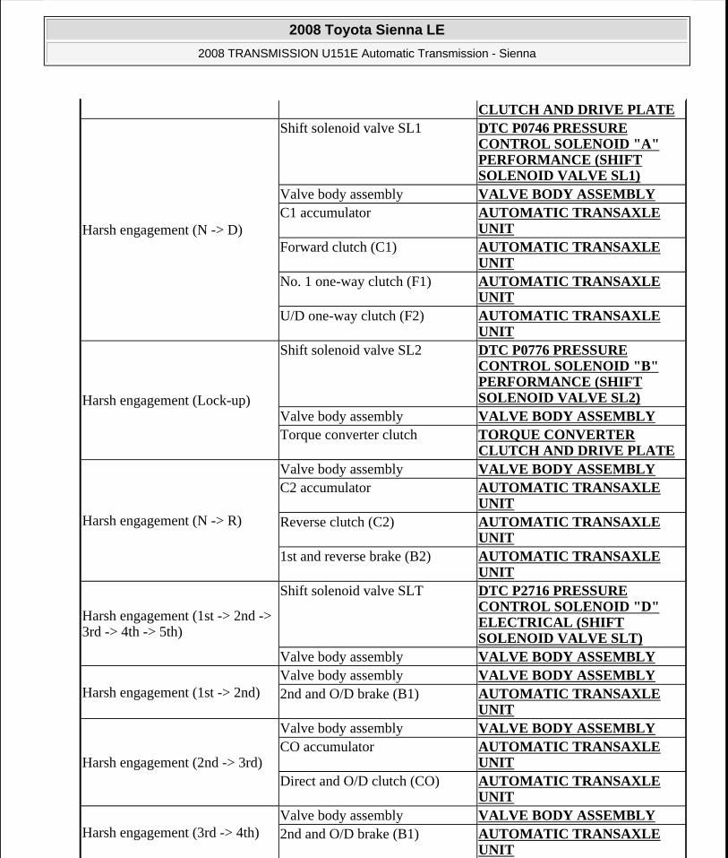
Harsh engagement (N -> D)
Shift solenoid valve SL1 DTC P0746 PRESSURE CONTROL SOLENOID "A" PERFORMANCE (SHIFT SOLENOID VALVE SL1)
Valve body assembly VALVE BODY ASSEMBLYC1 accumulator AUTOMATIC TRANSAXLE
UNITForward clutch (C1) AUTOMATIC TRANSAXLE
UNITNo. 1 one-way clutch (F1) AUTOMATIC TRANSAXLE
UNITU/D one-way clutch (F2) AUTOMATIC TRANSAXLE
UNIT
Harsh engagement (Lock-up)
Shift solenoid valve SL2 DTC P0776 PRESSURE CONTROL SOLENOID "B" PERFORMANCE (SHIFT SOLENOID VALVE SL2)
Valve body assembly VALVE BODY ASSEMBLYTorque converter clutch TORQUE CONVERTER
CLUTCH AND DRIVE PLATE
Harsh engagement (N -> R)
Valve body assembly VALVE BODY ASSEMBLYC2 accumulator AUTOMATIC TRANSAXLE
UNITReverse clutch (C2) AUTOMATIC TRANSAXLE
UNIT1st and reverse brake (B2) AUTOMATIC TRANSAXLE
UNIT
Harsh engagement (1st -> 2nd -> 3rd -> 4th -> 5th)
Shift solenoid valve SLT DTC P2716 PRESSURE CONTROL SOLENOID "D" ELECTRICAL (SHIFT SOLENOID VALVE SLT)
Valve body assembly VALVE BODY ASSEMBLY
Harsh engagement (1st -> 2nd)Valve body assembly VALVE BODY ASSEMBLY2nd and O/D brake (B1) AUTOMATIC TRANSAXLE
UNIT
Harsh engagement (2nd -> 3rd)
Valve body assembly VALVE BODY ASSEMBLYCO accumulator AUTOMATIC TRANSAXLE
UNITDirect and O/D clutch (CO) AUTOMATIC TRANSAXLE
UNIT
Harsh engagement (3rd -> 4th)Valve body assembly VALVE BODY ASSEMBLY2nd and O/D brake (B1) AUTOMATIC TRANSAXLE
UNIT
2008 Toyota Sienna LE
2008 TRANSMISSION U151E Automatic Transmission - Sienna
Microsoft
Wednesday, August 12, 2009 2:03:22 PM Page 25 © 2005 Mitchell Repair Information Company, LLC.

Harsh engagement (4th -> 5th)
Valve body assembly VALVE BODY ASSEMBLYC3 accumulator AUTOMATIC TRANSAXLE
UNITU/D clutch (B3) AUTOMATIC TRANSAXLE
UNIT
Harsh engagement (5th -> 4th)Valve body assembly VALVE BODY ASSEMBLYB3 accumulator AUTOMATIC TRANSAXLE
UNIT
Slip or shudder (Forward and reverse: After warm-up)
Valve body assembly VALVE BODY ASSEMBLYOil strainer VALVE BODY ASSEMBLYDirect and O/D clutch (CO) AUTOMATIC TRANSAXLE
UNITForward clutch (C1) AUTOMATIC TRANSAXLE
UNITU/D clutch (C3) AUTOMATIC TRANSAXLE
UNIT2nd and brake (B1) AUTOMATIC TRANSAXLE
UNITU/D brake (B3) AUTOMATIC TRANSAXLE
UNITNo. 1 one-way clutch (F1) AUTOMATIC TRANSAXLE
UNITU/D one-way clutch (F2) AUTOMATIC TRANSAXLE
UNITTorque converter clutch TORQUE CONVERTER
CLUTCH AND DRIVE PLATESlip or shudder (Particular position: Just after engine starts)
Torque converter clutch TORQUE CONVERTER CLUTCH AND DRIVE PLATE
Slip or shudder (R position)
Reverse clutch (C2) AUTOMATIC TRANSAXLE UNIT
1st and reverse brake (B2) AUTOMATIC TRANSAXLE UNIT
Slip or shudder (1st)
Forward clutch (C1) AUTOMATIC TRANSAXLE UNIT
No. 1 one-way clutch (F1) AUTOMATIC TRANSAXLE UNIT
U/D one-way clutch (F2) AUTOMATIC TRANSAXLE UNIT
Slip or shudder (2nd) 2nd and O/D brake (B1) AUTOMATIC TRANSAXLE UNIT
Slip or shudder (3rd) Direct and O/D clutch (CO) AUTOMATIC TRANSAXLE UNIT
Slip or shudder (4th) 2nd and O/D brake (B1) AUTOMATIC TRANSAXLE UNIT
2008 Toyota Sienna LE
2008 TRANSMISSION U151E Automatic Transmission - Sienna
Microsoft
Wednesday, August 12, 2009 2:03:22 PM Page 26 © 2005 Mitchell Repair Information Company, LLC.
TERMINALS OF ECM
1. ECM
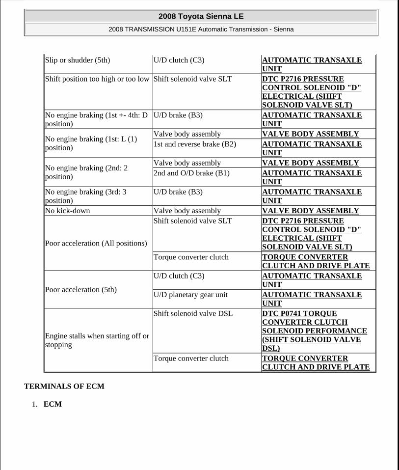
Slip or shudder (5th) U/D clutch (C3) AUTOMATIC TRANSAXLE UNIT
Shift position too high or too low Shift solenoid valve SLT DTC P2716 PRESSURE CONTROL SOLENOID "D" ELECTRICAL (SHIFT SOLENOID VALVE SLT)
No engine braking (1st +- 4th: D position)
U/D brake (B3) AUTOMATIC TRANSAXLE UNIT
No engine braking (1st: L (1) position)
Valve body assembly VALVE BODY ASSEMBLY1st and reverse brake (B2) AUTOMATIC TRANSAXLE
UNIT
No engine braking (2nd: 2 position)
Valve body assembly VALVE BODY ASSEMBLY2nd and O/D brake (B1) AUTOMATIC TRANSAXLE
UNITNo engine braking (3rd: 3 position)
U/D brake (B3) AUTOMATIC TRANSAXLE UNIT
No kick-down Valve body assembly VALVE BODY ASSEMBLY
Poor acceleration (All positions)
Shift solenoid valve SLT DTC P2716 PRESSURE CONTROL SOLENOID "D" ELECTRICAL (SHIFT SOLENOID VALVE SLT)
Torque converter clutch TORQUE CONVERTER CLUTCH AND DRIVE PLATE
Poor acceleration (5th)
U/D clutch (C3) AUTOMATIC TRANSAXLE UNIT
U/D planetary gear unit AUTOMATIC TRANSAXLE UNIT
Engine stalls when starting off or stopping
Shift solenoid valve DSL DTC P0741 TORQUE CONVERTER CLUTCH SOLENOID PERFORMANCE (SHIFT SOLENOID VALVE DSL)
Torque converter clutch TORQUE CONVERTER CLUTCH AND DRIVE PLATE
2008 Toyota Sienna LE
2008 TRANSMISSION U151E Automatic Transmission - Sienna
Microsoft
Wednesday, August 12, 2009 2:03:22 PM Page 27 © 2005 Mitchell Repair Information Company, LLC.

Fig. 7: Identifying ECM Terminals Courtesy of TOYOTA MOTOR SALES, U.S.A., INC.
HINT:
Each ECM terminal's standard voltage is shown in the table below.
In the table, first follow the information under "Condition". Look under "Symbols (Terminal No.)" for the terminals to inspected. The standard voltage between the terminals is shown under "Specific Condition".
Use the illustration above as a reference for the ECM terminals.
ECM TERMINALS VOLTAGE SPECIFICATION Symbols
(Terminals No.) Wiring ColorTerminal
Description ConditionSpecified Condition
L(E5-9)-E1(E11-1) L-BRL shift position switch signal
IG switch ON and shift lever L position
11 to 14 V
IG switch ON and shift lever other than L position
Below 1 V
2(E5-10)-E1 (E11-1) Y-G - BR
2 shift position switch signal
IG switch ON and shift lever 2 and L position
11 to 14 V
IG switch ON and shift lever other than 2 and L position
Below 1 V
D(E5-21)-E1(E11-1)
L-W - BR D shift position switch signal
IG switch ON and shift lever D and 4 position
11 to 14 V
IG switch ON and shift lever other than D and 4 position
Below 1 V
R(E5-11)-E1(E11-1) R-B - BRR shift position switch signal
IG switch ON and shift lever R position
11 to 14 V
IG switch ON and shift lever other than R position
Below 1 V
SPD(E5-8)-E1 V-W - BR Speed signal Vehicle speed 20 Pulse generation
2008 Toyota Sienna LE
2008 TRANSMISSION U151E Automatic Transmission - Sienna
Microsoft
Wednesday, August 12, 2009 2:03:22 PM Page 28 © 2005 Mitchell Repair Information Company, LLC.

(E11-1) km/h (12 mph) (See g waveform 8)
STP(E4-15)-E1 (E11-1)
G-W - BRStop light switch
signal
Brake pedal is depressed
7.5 to 14 V
Brake pedal is released
Below 1.5 V
3(E5-19)-E1 (E11-1)
G-BR3 shift position switch signal
IG switch ON and shift lever 3 position
11 to 14 V
IG switch ON and shift lever other than 3 position
Below 1 V
4(E5-20)-E1 (E11-1)
B-W - BR 4 shift position switch signal
IG switch ON and shift lever 4 position
11 to 14 V
IG switch ON and shift lever other than 4 position
Below 1 V
NSW (STAR) (E10-8) - E1 (E11-1)
B-Y - BRPark neutral switch
signal
IG switch ON and shift lever P and N position
Below 1 V
IG switch ON and shift lever other than P and N position
11 to 14 V
P(E5-23)-E1 (E11-1)
L-Y - BRPark position switch
signal
IG switch ON and shift lever P position
11 to 14 V
IG switch ON and shift lever other then P position
Below 1 V
N(E5-22)-E1 (E11-1)
Y-R - BRNeutral position
switch signal
IG switch ON and shift lever N position
11 to 14 V
IG switch ON and shift lever other then N position
Below 1 V
DSL(E10-11)-E1 (E11-1)
Y-G - BR DSL solenoid signal Vehicle speed 65 km/h (40 mph), lock-up (ON to OFF)
Pulse generation (See a waveform 2)
SR(E10-9)-E1 (E11-1)
L-B - BR SR solenoid signalIG switch ON Below 1 V3rd, 4th or 5th gear 11 to 14 V1st or 2nd gear Below 1 V
S4(E10-10)-E1 (E11-1)
L-W - BR S4 solenoid signalIG switch ON Below 1 V5th gear 11 to 14 VExcept 5th gear Below 1 V
SL3+ (E10-17) - SL3- (E10-16)
G-B - G-R SL3 solenoid signal Engine idle speed Pulse generation (See b waveform 3)
2008 Toyota Sienna LE
2008 TRANSMISSION U151E Automatic Transmission - Sienna
Microsoft
Wednesday, August 12, 2009 2:03:22 PM Page 29 © 2005 Mitchell Repair Information Company, LLC.

a. Waveform 1
Reference:
WAVEFORM REFERENCE (WAVEFORM 1)
Fig. 8: Waveform Graph (Waveform 1) Courtesy of TOYOTA MOTOR SALES, U.S.A., INC.
b. Waveform 2
Reference:
WAVEFORM REFERENCE (WAVEFORM 2)
SL2+ (E10-15) - SL2- (E10-14)
L-Y - L-R SL2 solenoid signal Engine idle speed Pulse generation (See c waveform 4)
SL1+(E10-19)-SL1-(E10-18)
R-B - B-W SL1 solenoid signal Engine idle speed Pulse generation (See d waveform 5)
NC+ (E10-34)-NC-(E10-26)
R-W-G Speed sensor (NC) signal
Vehicle speed 30 km/h (19 mph): (3rd gear) Engine speed 1,400 rpm
Pulse generation (See e waveform 6)
NT+ (E10-35)- NT- (E10-27)
W-R-W Speed sensor (NT) signal
Vehicle speed 20 km/h (12mph)
Pulse generation (See f waveform 7)
SLT+ (E10-13) - SLT-(E10-12)
Y-R-Y-B SLT solenoid signal Engine idle speed Pulse generation (See waveform 1)
THO1 (E10-24)-E2(E9-28)
G-Y - BR ATF temperature sensor signal
ATF temperature: 115°C (239°F) or more
Below 1.5 V
Terminal SLT+ - SLT-Tool setting 5 V/DIV, 1 ms./DIVVehicle condition Engine idle speed
Terminal DSL-E1Tool setting 10 V/DIV, 100ms./DIV
2008 Toyota Sienna LE
2008 TRANSMISSION U151E Automatic Transmission - Sienna
Microsoft
Wednesday, August 12, 2009 2:03:23 PM Page 30 © 2005 Mitchell Repair Information Company, LLC.

Fig. 9: Waveform Graph (Waveform 2) Courtesy of TOYOTA MOTOR SALES, U.S.A., INC.
c. Waveform 3
Reference:
WAVEFORM REFERENCE (WAVEFORM 3)
Fig. 10: Waveform Graph (Waveform 3) Courtesy of TOYOTA MOTOR SALES, U.S.A., INC.
d. Waveform 4
Reference:
WAVEFORM REFERENCE (WAVEFORM 4)
Vehicle condition Vehicle speed 65 km/h (40 mph), lock-up (ON to OFF)
Terminal SL3+ - SL3-Tool setting 5 V/DIV, 1 ms./DIVVehicle condition Engine idle speed
Terminal SL2+ - SL2-Tool setting 5 V/DIV, 1 ms./DIVVehicle condition Engine idle speed
2008 Toyota Sienna LE
2008 TRANSMISSION U151E Automatic Transmission - Sienna
Microsoft
Wednesday, August 12, 2009 2:03:23 PM Page 31 © 2005 Mitchell Repair Information Company, LLC.

Fig. 11: Waveform Graph (Waveform 4) Courtesy of TOYOTA MOTOR SALES, U.S.A., INC.
e. Waveform 5
Reference:
WAVEFORM REFERENCE (WAVEFORM 5)
Fig. 12: Waveform Graph (Waveform 5) Courtesy of TOYOTA MOTOR SALES, U.S.A., INC.
f. Waveform 6
Reference:
WAVEFORM REFERENCE (WAVEFORM 6)
Terminal SL1+-SL1-Tool setting 5 V/DIV, 1 ms./DIVVehicle condition Engine idle speed
Terminal NC+-NC-Tool setting 1 V/DIV, 1 ms./DIVVehicle condition Vehicle speed 30 km/h (19 mph): (3rd gear)
Engine speed 1.400 rpm
2008 Toyota Sienna LE
2008 TRANSMISSION U151E Automatic Transmission - Sienna
Microsoft
Wednesday, August 12, 2009 2:03:23 PM Page 32 © 2005 Mitchell Repair Information Company, LLC.

Fig. 13: Waveform Graph (Waveform 6) Courtesy of TOYOTA MOTOR SALES, U.S.A., INC.
g. Waveform 7
Reference:
WAVEFORM REFERENCE (WAVEFORM 7)
Fig. 14: Waveform Graph (Waveform 7) Courtesy of TOYOTA MOTOR SALES, U.S.A., INC.
h. Waveform 8
Reference:
WAVEFORM REFERENCE (WAVEFORM 8)
Terminal NT+ - NT-Tool setting 5 V/DIV, 0.5ms./DIVVehicle condition Vehicle speed 20 km/h (12 mph)
Terminal SPD-E1Tool setting 5 V/DIV, 20ms./DIVVehicle condition Vehicle speed 20 km/h (12 mph)
2008 Toyota Sienna LE
2008 TRANSMISSION U151E Automatic Transmission - Sienna
Microsoft
Wednesday, August 12, 2009 2:03:23 PM Page 33 © 2005 Mitchell Repair Information Company, LLC.
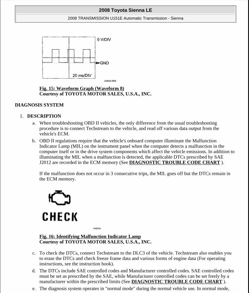
Fig. 15: Waveform Graph (Waveform 8) Courtesy of TOYOTA MOTOR SALES, U.S.A., INC.
DIAGNOSIS SYSTEM
1. DESCRIPTION
a. When troubleshooting OBD II vehicles, the only difference from the usual troubleshooting procedure is to connect Techstream to the vehicle, and read off various data output from the vehicle's ECM.
b. OBD II regulations require that the vehicle's onboard computer illuminate the Malfunction Indicator Lamp (MIL) on the instrument panel when the computer detects a malfunction in the computer itself or in the drive system components which affect the vehicle emissions. In addition to illuminating the MIL when a malfunction is detected, the applicable DTCs prescribed by SAE J2012 are recorded in the ECM memory (See DIAGNOSTIC TROUBLE CODE CHART ).
If the malfunction does not occur in 3 consecutive trips, the MIL goes off but the DTCs remain in the ECM memory.
Fig. 16: Identifying Malfunction Indicator Lamp Courtesy of TOYOTA MOTOR SALES, U.S.A., INC.
c. To check the DTCs, connect Techstream to the DLC3 of the vehicle. Techstream also enables you to erase the DTCs and check freeze frame data and various forms of engine data (For operating instructions, see the instruction book).
d. The DTCs include SAE controlled codes and Manufacturer controlled codes. SAE controlled codes must be set as prescribed by the SAE, while Manufacturer controlled codes can be set freely by a manufacturer within the prescribed limits (See DIAGNOSTIC TROUBLE CODE CHART ).
e. The diagnosis system operates in "normal mode" during the normal vehicle use. In normal mode,
2008 Toyota Sienna LE
2008 TRANSMISSION U151E Automatic Transmission - Sienna
Microsoft
Wednesday, August 12, 2009 2:03:23 PM Page 34 © 2005 Mitchell Repair Information Company, LLC.

"2-trip detection logic" is used to ensure accurate detection of malfunction. "Check mode" is also available to technicians as an option. In check mode, "1 -trip detection logic" is used for simulating malfunction symptoms and increasing the system's ability to detect malfunctions, including intermittent malfunction.
f. *2 trip detection logic: When a malfunction is first detected, the malfunction is temporarily stored in the ECM memory (1st trip). If the ignition switch is turned off and then turned to the ON position again, and same malfunction is detected again, the MIL will illuminate.
g. Freeze frame data records the engine conditions (fuel system, calculated load, engine coolant temperature, fuel trim, engine speed, vehicle speed, etc.) when a malfunction is detected. When troubleshooting, freeze frame data can help determine if the vehicle was running or stopped, if the engine was warmed up or not, if the air/fuel ratio was Lean or Rich, and other data from the time the malfunction occurred.
h. Techstream records freeze frame data in five different instance: 1) 3 times before the DTC is set, 2) once when the DTC is set, and 3) once after the DTC is set. These data can be used to simulate the vehicle's condition around the time when the malfunction occurred. The data may help find the cause of the malfunction, or judge if the DTC is being caused by temporary malfunction or not.
Fig. 17: DTC Timing Chart Courtesy of TOYOTA MOTOR SALES, U.S.A., INC.
2. INSPECT THE DLC3
a. The vehicle's ECM uses ISO 15765-4 for communication. The terminal arrangement of the DLC3 complies with SAE J1962 and matches the ISO 15765-4 format.
Fig. 18: Identifying DLC3 Connector Terminals Courtesy of TOYOTA MOTOR SALES, U.S.A., INC.
Terminals of DLC3
2008 Toyota Sienna LE
2008 TRANSMISSION U151E Automatic Transmission - Sienna
Microsoft
Wednesday, August 12, 2009 2:03:23 PM Page 35 © 2005 Mitchell Repair Information Company, LLC.

DLC3 CONNECTOR TERMINALS RESISTANCE SPECIFICATION
HINT:
If your display shows UNABLE TO CONNECT TO VEHICLE when you have connected the cable of Techstream to the DLC3, turned the ignition switch to the ON position and operated the scan tool, there is a problem on the vehicle side or tool side.
If the communication is normal when the tool is connected to another vehicle, inspect the DLC3 on the original vehicle.
If the communication is still impossible when the tool is connected to another vehicle, the problem is probably in the tool itself, so consult the Service Department listed in the tool's instruction manual.
3. CHECK BATTERY VOLTAGE
a. Measure the battery voltage.
Battery voltage: 11 to 14 V
If voltage is below 11 V, replace the battery before proceeding.
4. CHECK MIL
Symbol Terminal No. NameReference Terminal Result Condition
SIL 7 Bus "+" line 5 - Signal ground
Pulse generation
During transmission
CG 4 Chassis ground
Body ground Below 1 ohms Always
SG 5 Signal ground Body ground Below 1 ohms AlwaysBAT 16 Battery
positiveBody ground 11 to 14 V Always
CANH 6 HIGH-level CAN bus line
CANL 54 to 69 ohms IG switch OFF
CANH 6 HIGH-level CAN bus line
Battery positive 6 kohms or higher
IG switch OFF
CANH 6 HIGH-level CAN bus line
CG 200 ohms or higher
IG switch OFF
CANL 14 LOW-level CAN bus line
Battery positive 6 kohms or higher
IG switch OFF
CANL 14 LOW-level CAN bus line
CG 200 ohms or higher
IG switch OFF
CAUTION: *: Before measuring the resistance, leave the vehicle as is for at least 1 minute and do not operate the ignition switch, any other switches or the doors.
2008 Toyota Sienna LE
2008 TRANSMISSION U151E Automatic Transmission - Sienna
Microsoft
Wednesday, August 12, 2009 2:03:23 PM Page 36 © 2005 Mitchell Repair Information Company, LLC.

a. The MIL comes on when the ignition switch is turned to the ON position and the engine is not running.
HINT:
If the MIL does not light up, troubleshoot the combination meter.
b. When the engine is started, the MIL should go off. If the lamp remains on, it means that the diagnosis system has detected a malfunction or abnormality in the system.
DTC CHECK / CLEAR
1. DTC CHECK (NORMAL MODE)
a. Checking DTCs using Techstream.
1. Turn the ignition switch off.
2. Connect Techstream to the DLC3.
3. Turn the ignition switch to the ON position and turn Techstream main switch on.
4. Enter the following menus: Powertrain / Engine and ECT / Trouble Codes.
5. Use Techstream to check the DTCs and freeze frame data and note them down (For operating instructions, see the Techstream's instruction book).
Turn the ignition switch off after the symptom is simulated once. Then repeat the simulation process again. When the problem has been simulated twice, the MIL illuminates and the DTCs are recorded in the ECM.
2. DTC CLEAR
a. When using Techstream: Clearing the DTCs.
1. Connect Techstream to the DLC3.
2. Turn the ignition switch to the ON position and turn the Techstream main switch on.
3. Enter the following menus: Powertrain / Engine and ECT / Trouble Codes / Clear.
HINT:
When operating Techstream to erase the codes, the DTCs and freeze frame data will be
NOTE: When the diagnostic system is switched from the normal mode to the check mode, all the DTCs and freeze frame data recorded in the normal mode will be erased. So before switching modes, always check the DTCs and freeze frame data, and note them down.
NOTE: When simulating symptoms with Techstream to check the DTCs, use the normal mode. For codes on the DTCs chart which are subject to "2 trip detection logic",
2008 Toyota Sienna LE
2008 TRANSMISSION U151E Automatic Transmission - Sienna
Microsoft
Wednesday, August 12, 2009 2:03:23 PM Page 37 © 2005 Mitchell Repair Information Company, LLC.

erased. (See the Techstream's instruction book for operating instructions.)
b. When not using Techstream: Clearing the DTCs.
1. Disconnect the battery terminal or remove the EFI and ETCS fuses from the engine room J/B for 60 seconds or more. However, if you disconnect the battery terminal, perform the "INITIALIZE" procedure.
CHECK MODE PROCEDURE
HINT:
Check mode has a higher sensitivity to malfunctions and can detect malfunction that normal mode cannot detect. Check mode can also detect all the malfunctions that normal mode can detect. In check mode, DTCs are detected with 1 -trip detection logic.
1. DTC CHECK (CHECK MODE)
HINT:
Techstream only: Compared to the normal mode, the check mode is more sensitive for detecting malfunctions. Furthermore, the same diagnostic items which are detected in the normal mode can also be detected in the check mode.
a. Procedure for Check Mode using Techstream.
1. Check the initial conditions.
Battery positive voltage 11 V or more
Throttle valve fully closed
Transaxle in the P or N position
A/C switch is off
2. Turn the ignition switch off.
3. Connect Techstream to the DLC3.
4. Turn the ignition switch to ON position and turn the Techstream main switch on.
5. Enter the following menus: Powertrain / Engine and ECT / Utility / Check Mode.
NOTE: All DTCs and freeze frame data recorded will be erased if: 1) Techstream is used to change the ECM from normal mode to check mode or vice-versa; or 2) during check mode, the ignition switch is turned from the ON to ACC position or turned OFF.
2008 Toyota Sienna LE
2008 TRANSMISSION U151E Automatic Transmission - Sienna
Microsoft
Wednesday, August 12, 2009 2:03:23 PM Page 38 © 2005 Mitchell Repair Information Company, LLC.

Fig. 19: Identifying MIL Flashes Courtesy of TOYOTA MOTOR SALES, U.S.A., INC.
6. Start the engine (the MIL goes off after the engine starts).
7. Perform "MONITOR DRIVE PATTERN" for the ECT test. (Or, simulate the conditions of the malfunction described by the customer).
8. After simulating malfunction conditions, use the Techstream diagnosis selector to check the DTCs and freeze frame data, etc.
9. When you use Techstream: Enter the following menus: Powertrain / Engine and ECT / Trouble Codes.
10. After checking the DTC, inspect the applicable circuit.
11. See DIAGNOSTIC TROUBLE CODE CHART to confirm the details of the DTCs.
2. DTC CLEAR
a. When using Techstream: Clearing the DTCs.
1. Connect Techstream to the DLC3.
2. Turn the ignition switch to the ON position and turn the Techstream main switch on.
3. When you use Techstream: Enter the following menus: Powertrain / Engine and ECT / Trouble Codes / Clear.
HINT:
When operating Techstream to erase the codes, the DTCs and freeze frame data will be erased. (See the Techstream's instruction book for operating instructions.)
b. When not using Techstream: Clearing the DTCs.
1. Disconnect the battery cable or remove the EFI and ETCS fuses from the engine room J/B for 60 seconds or more. However, if you disconnect the battery cable, perform the "INITIALIZE" procedure.
FAIL-SAFE CHART
NOTE: Leave the ignition switch in the ON position until you have checked the DTCs, etc.
2008 Toyota Sienna LE
2008 TRANSMISSION U151E Automatic Transmission - Sienna
Microsoft
Wednesday, August 12, 2009 2:03:23 PM Page 39 © 2005 Mitchell Repair Information Company, LLC.

1. FAIL-SAFE
This function minimizes the loss of the ECT functions when any malfunction occurs in a sensor or solenoid.
a. ATF (Automatic Transmission Fluid) temperature sensor:
When the ATF temperature sensor has a malfunction, 5th upshift is prohibited.
b. Counter gear speed sensor NC (Speed sensor NC): When the counter gear speed sensor has a malfunction, 5th upshift is prohibited.
c. Shift solenoid valve DSL:
When the solenoid valve DSL has a malfunction, the current to the solenoid valve is stopped. This stops lock-up control, then fuel economy decreases.
d. Shift solenoid valve SL1, SL2, SL3 and S4:
Fail safe function:
If either of the shift solenoid valve circuits develops an open or short, the ECM turns the other shift solenoid "ON" and "OFF" in order to shift into the gear positions shown in the table below.
Manual shifting as shown in the following table must be done (In case of a short circuit, the ECM stops sending the current to the short circuited solenoid).
Even if starting the engine in the fail-safe mode, the gear position remains in the same position.
HINT:
FL: Flex Lock-up
FAIL-SAFE CHART
NormalSolenoid Valve
SL1 ON OFF ON OFF OFFSL2 ON ON OFF FL FLSL3 OFF OFF OFF ON ONS4 OFF OFF OFF OFF ON
Gear Position 1st 2nd 3rd 4th 5th
SL1 Malfunction (During driving at 1st or 2nd)
Solenoid Valve
SL1 OFFSL2 ON ON OFF to ON FL to ON FL to ONSL3 OFF OFF OFF ON to OFF ON to OFFS4 OFF OFF OFF OFF ON to OFF
Gear Position 1st to 2nd 2nd 3rd to 2nd 4th to 2nd 5th to 2nd
SL1 SL1 OFF
2008 Toyota Sienna LE
2008 TRANSMISSION U151E Automatic Transmission - Sienna
Microsoft
Wednesday, August 12, 2009 2:03:23 PM Page 40 © 2005 Mitchell Repair Information Company, LLC.

DATA LIST / ACTIVE TEST
1. DATA LIST
HINT:
Using Techstream to read the Data List allows the values or states of switches, sensors, actuators and other items to be read without removing any parts. This non-intrusive inspection can be very useful because intermittent conditions or signals may be discovered before parts or wiring is disturbed. Reading the Data List information early in troubleshooting is one way to save diagnostic time.
Malfunction (During driving at 3rd)
Solenoid Valve
SL2 ON to FL ON to FL OFF to FL FL FLSL3 OFF OFF OFF ON to OFF ON to OFFS4 OFF to ON OFF to ON OFF to ON OFF to ON ON
Gear Position 1st to 4th 2nd to 4th 3rd to 4th 4th 5th to 4th
SL1 Malfunction (During driving at 4th or 5th)
Solenoid Valve
SL1 OFFSL2 ON to FL ON to FL OFF to FL FL FLSL3 OFF to ON OFF to ON OFF to ON ON ONS4 OFF OFF OFF OFF ON
Gear Position 1st to 4th 2nd to 4th 3rd to 4th 4th 5th to 4th
SL2 Malfunction
Solenoid Valve
SL1 ON OFF to ON ON OFF to ON OFF to ONSL2 OFFSL3 OFF OFF OFF ON to OFF ON to OFFS4 OFF to ON OFF to ON OFF to ON OFF to ON ON
Gear Position 1st to 4th 2nd to 4th 3rd to 4th 4th 5th to 4th
SL3 Malfunction
Solenoid Valve
SL1 ON OFF ON OFF to ON OFF to ONSL2 ON ON OFF FL FLSL3 OFFS4 OFF OFF OFF OFF to ON ON
Gear Position 1st 2nd 3rd 4th 5th to 4th
S4 Malfunction
Solenoid Valve
SL1 ON OFF ON OFF OFFSL2 ON ON OFF FL FLSL3 OFF OFF OFF ON ONS4 OFF
Gear Position 1st 2nd 3rd 4th 5th to 4th
SL1, SL2, SL3, and S4 Malfunction
Solenoid Valve
SL1 OFFSL2 OFFSL3 OFFS4 OFF
Gear Position 1st to 4th 2nd to 4th 3rd to 4th 4th 5th to 4th
NOTE: In the table below, the values listed under "Normal Condition" are
2008 Toyota Sienna LE
2008 TRANSMISSION U151E Automatic Transmission - Sienna
Microsoft
Wednesday, August 12, 2009 2:03:23 PM Page 41 © 2005 Mitchell Repair Information Company, LLC.

a. Warm up the engine.
b. Turn the ignition switch off.
c. Connect Techstream to the DLC3.
d. Turn the ignition switch to the ON position.
e. Turn on the tester.
f. Select the item: Powertrain / Engine and ECT / Data List.
g. According to the display on the tester, read the "Data List".
DATA LIST
reference values. Do not depend solely on these reference values when deciding whether a part is faulty or not.
Tester DisplayMeasurement Item/Range Normal Condition Diagnostic Note
Stop Light SwitchStop light switch Status/ ON or OFF
Brake Pedal is depressed: ON
Brake Pedal is released: OFF
-
Neutral Position SW signal
PNP switch Status/ ON or OFF
Shift lever position is; P and N: ON Except P and N: OFF
When the shift lever position displayed on the Intelligent tester differs from the actual position, adjustment of the PNP switch or the shift cable may be incorrect. HINT: When the failure still occurs even after adjusting these parts, See DTC P0705 TRANSMISSION RANGE SENSOR CIRCUIT MALFUNCTION (PRNDL INPUT) .
Shift SW Status (P Range)
PNP switch Status/ ON or OFF
Shift lever position is: P: ON Except P: OFF
?
Shift SW Status (N Range)
PNP switch Status/ ON or OFF
Shift lever position is: N:ON Except N: OFF
?
Shift SW Status (R Range)
PNP switch Status/ ON or OFF
Shift lever position is; R: ON Except R: OFF
?
2008 Toyota Sienna LE
2008 TRANSMISSION U151E Automatic Transmission - Sienna
Microsoft
Wednesday, August 12, 2009 2:03:23 PM Page 42 © 2005 Mitchell Repair Information Company, LLC.

Shift SW Status (D Range)
PNP switch Status/ ON or OFF
Shift lever position is; D and 4: ON Except D and 4: OFF
?
Shift SW Status (2 Range)
PNP SW Status/ON or OFF
Shift lever position is; 2 and L: ON Except 2 and L: OFF
?
Shift SW Status (L Range)
PNP SW Status/ ON or OFF
Shift lever position is; L: ON Except L: OFF
?
Shift SW Status (4 or D)
PNP SW Status/ ON or OFF
Shift lever position is; 4: ON Except 4: OFF
?
Shift SW Status (3 Range)
PNP SW Status/ ON or OFF
Shift lever position is; 3: ON Except 3: OFF
?
Shift SW StatusActual Gear Position/ 1st, 2nd, 3rd, 4th or 5th (O/D)
Shift lever position is;
L: 1st
2: 1st or 2nd
3: 1st, 2nd or 3rd
4: 1st, 2nd, 3rd or 4th
D (O/D ON): 1st, 2nd, 3rd, 4th or 5th
-
Lock UpLock Up Status/ ON or OFF
Lock Up: ON
Except Lock Up: OFF
-
Lock Up Solenoid Status
Lock Up Solenoid Status/ ON or OFF
Lock Up: ON
Except Lock Up: OFF
-
SLT Solenoid StatusShift Solenoid SLT Status/ ON or OFF
Accelerator pedal is depressed: OFF
Accelerator pedal is released: ON
-
A/T Oil Temperature 1
ATF Temp. Sensor Value/ min.: -40°C (-40°F) max.: 215°C (419°F)
After Stall Test; Approx. 80°C (176°F)
Equal to ambient temperature when cold soak
If the value is "-40°C (-40°F)" or "215°C (419°F)n, ATF temp, sensor circuit is opened or shorted.
HINT:
2008 Toyota Sienna LE
2008 TRANSMISSION U151E Automatic Transmission - Sienna
Microsoft
Wednesday, August 12, 2009 2:03:23 PM Page 43 © 2005 Mitchell Repair Information Company, LLC.
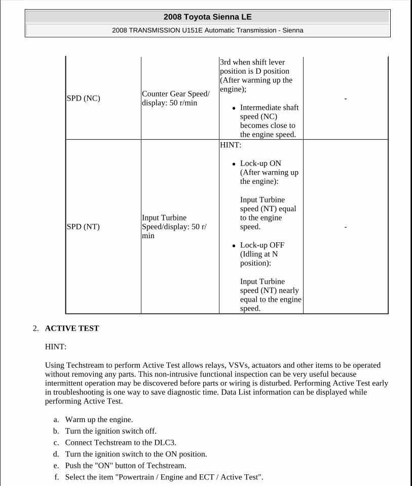
2. ACTIVE TEST
HINT:
Using Techstream to perform Active Test allows relays, VSVs, actuators and other items to be operated without removing any parts. This non-intrusive functional inspection can be very useful because intermittent operation may be discovered before parts or wiring is disturbed. Performing Active Test early in troubleshooting is one way to save diagnostic time. Data List information can be displayed while performing Active Test.
a. Warm up the engine.
b. Turn the ignition switch off.
c. Connect Techstream to the DLC3.
d. Turn the ignition switch to the ON position.
e. Push the "ON" button of Techstream.
f. Select the item "Powertrain / Engine and ECT / Active Test".
SPD (NC)Counter Gear Speed/ display: 50 r/min
3rd when shift lever position is D position (After warming up the engine);
Intermediate shaft speed (NC) becomes close to the engine speed.
-
SPD (NT)Input Turbine Speed/display: 50 r/ min
HINT:
Lock-up ON (After warning up the engine):
Input Turbine speed (NT) equal to the engine speed.
Lock-up OFF (Idling at N position):
Input Turbine speed (NT) nearly equal to the engine speed.
-
2008 Toyota Sienna LE
2008 TRANSMISSION U151E Automatic Transmission - Sienna
Microsoft
Wednesday, August 12, 2009 2:03:23 PM Page 44 © 2005 Mitchell Repair Information Company, LLC.

g. According to the display on tester, perform the "active Test".
ACTIVE TEST DETAIL Tester Display Test Part Control Range Diagnostic Note
Control the Shift Position
[Test Details] Operate the shift solenoid valve and set the each shift position by yourself. [Vehicle Condition]
IDL: ON
Less than 50 km/h (31 mph)
[Others]
Press "-->" button: Shift up
Press "<--" button: Shift down
1st/2nd/3rd/4th/5thPossible to check the operation of the shift solenoid valves.
Activate the Lock Up
[Test Details] Control the shift solenoid DSL to set the automatic transaxle to the lock-up condition. [Vehicle Condition]
Throttle valve opening angle: Less than 35 %
Vehicle Speed: 60 km/h (37 mph) or more, and 5th gear
ON/OFFPossible to check the DSL operation.
Activate the Solenoid (SL1)
[Test Details] Operate the shift solenoid SL1 [Vehicle Condition]
Vehicle Stopped.
Shift lever P or N position
ON/OFF -
[Test Details]
2008 Toyota Sienna LE
2008 TRANSMISSION U151E Automatic Transmission - Sienna
Microsoft
Wednesday, August 12, 2009 2:03:23 PM Page 45 © 2005 Mitchell Repair Information Company, LLC.

Activate the Solenoid (SL2)
Operate the shift solenoid SL2 [Vehicle Condition]
Vehicle Stopped.
Shift lever P or N position
ON/OFF -
Activate the Solenoid (SL3)
[Test Details] Operate the shift solenoid SL3 [Vehicle Condition]
Vehicle Stopped.
Shift lever P or N position
ON/OFF -
Activate the Solenoid (S4)
[Test Details] Operate the shift solenoid S4 [Vehicle Condition]
Vehicle Stopped.
Shift lever P or N position
ON/OFF -
Activate the Solenoid (SR)
[Test Details] Operate the shift solenoid SR [Vehicle Condition]
Vehicle Stopped.
Shift lever P or N position
ON/OFF -
Activate the Solenoid (DSL)
[Test Details] Operate the shift solenoid DSL [Vehicle Condition]
Vehicle Stopped.
Shift lever P or N position
ON/OFF -
[Test Details] Operate the shift solenoid SLT and raise the line pressure. [Vehicle Condition]
2008 Toyota Sienna LE
2008 TRANSMISSION U151E Automatic Transmission - Sienna
Microsoft
Wednesday, August 12, 2009 2:03:23 PM Page 46 © 2005 Mitchell Repair Information Company, LLC.

HINT:
The pressure values in Active Test and HYDRAULIC TEST are different from each other.
DIAGNOSTIC TROUBLE CODE CHART
If a DTC is displayed during the DTC check, check the parts listed in the table below and proceed to the information given.
HINT:
*1: Comes on MIL (Malfunction Indicator Lamp) light up
*2: "DTC stored" mark means ECM memorizes the malfunction code if the ECM detects the DTC detection condition.
This DTC may be output when the clutch, brake and gear components etc. inside the automatic transmission are damaged.
AUTOMATIC TRANSAXLE SYSTEM:
DIAGNOSTIC TROUBLE CODE CHART
Activate the Solenoid (SLT)(1)
Vehicle Stopped.
IDL: ON
HINT: OFF: Line pressure up (When the active test of "Activate the Solenoid (SLT)" is performed, the ECM commands the SLT solenoid to turn off). ON: No action (normal operation)
ON/OFF -
(1) "Activate the Solenoid (SLT)" in the Active Test is performed to check the line pressure changes by connecting the SST to the automatic transaxle, which is used in the HYDRAULIC TEST (See HYDRAULIC TEST ) as well.
DTC Code Detection Item Trouble Area MIL*1 Memory *2
P0705
Transmission Range Sensor Circuit Malfunction (PRNDL Input)
1. Open or short in park/neutral position switch circuit
2. Park/neutral position switch
Comes on DTC stored
2008 Toyota Sienna LE
2008 TRANSMISSION U151E Automatic Transmission - Sienna
Microsoft
Wednesday, August 12, 2009 2:03:23 PM Page 47 © 2005 Mitchell Repair Information Company, LLC.

3. ECM
P0710Transmission Fluid Temperature Sensor "A" Circuit
1. Open or short in ATF temperature sensor circuit
2. Transmission wire (ATF temperature sensor)
3. ECM
Comes on DTC stored
P0711 Transmission Fluid Temperature Sensor "A" Performance
Transmission wire (ATF temperature sensor)
Comes on DTC stored
P0712
Transmission Fluid Temperature Sensor "A" Circuit Low Input
1. Short in ATF temperature sensor circuit
2. Transmission wire (ATF temperature sensor)
3. ECM
Comes on DTC stored
P0713
Transmission Fluid Temperature Sensor "A" Circuit High Input
1. Open in ATF temperature sensor circuit
2. Transmission wire (ATF temperature sensor)
3. ECM
Comes on DTC stored
P0717Turbine Speed Sensor Circuit No Signal
1. Open or short in transmission revolution sensor NT (speed sensor NT) circuit
2. Transmission revolution sensor NT (speed sensor NT)
3. ECM
4. Automatic transaxle
Comes on DTC stored
2008 Toyota Sienna LE
2008 TRANSMISSION U151E Automatic Transmission - Sienna
Microsoft
Wednesday, August 12, 2009 2:03:23 PM Page 48 © 2005 Mitchell Repair Information Company, LLC.

assembly
P0724Brake Switch "B" Circuit High
1. Short in stop light switch circuit
2. Stop light switch
3. ECM
Comes on DTC stored
P0741
Torque Converter Clutch Solenoid Performance (Shift Solenoid Valve DSL)
1. Shift solenoid valve DSL remains open or closed
2. Valve body is blocked
3. Torque converter clutch
4. Automatic transaxle (clutch, brake or gear etc.)
5. Line pressure is too low
Comes on DTC stored
P0746
Pressure Control Solenoid "A" Performance (Shift Solenoid Valve SL1)
1. Shift solenoid valve SL1 remains open or closed
2. Valve body is blocked
3. Automatic transaxle (clutch, brake or gear etc.)
Comes on DTC stored
P0748
Pressure Control Solenoid "A" Electrical (Shift Solenoid Valve SL1)
1. Open or short in shift solenoid valve SL1 circuit
2. Shift solenoid valve SL1
3. ECM
Comes on DTC stored
Shift Solenoid "D"
1. Shift solenoid valve S4 remains open or closed
2. Valve body is
2008 Toyota Sienna LE
2008 TRANSMISSION U151E Automatic Transmission - Sienna
Microsoft
Wednesday, August 12, 2009 2:03:23 PM Page 49 © 2005 Mitchell Repair Information Company, LLC.

P0766
Performance (Shift Solenoid Valve S4)
blocked (Brake control valve)
3. Automatic transaxle (clutch, brake or gear, etc.)
Comes on DTC stored
P0771Shift Solenoid "E" Performance (Shift Solenoid Valve SR)
1. Shift solenoid valve SR remains open or closed
2. Valve body is blocked
3. Automatic transaxle (clutch, brake or gear etc.)
Comes on DTC stored
P0776
Pressure Control Solenoid "B" Performance (Shift Solenoid Valve SL2)
1. Shift solenoid valve SL2 remains open or closed
2. Valve body is blocked
3. Automatic transaxle (clutch, brake or gear etc.)
Comes on DTC stored
P0778
Pressure Control Solenoid "B" Electrical (Shift Solenoid Valve SL2)
1. Open or short in shift solenoid valve SL2 circuit
2. Shift solenoid valve SL2
3. ECM
Comes on DTC stored
P0793 Intermediate Shaft Speed Sensor "A"
1. Open or short in transmission revolution sensor NC (speed sensor NC) circuit
2. Transmission revolution sensor NC (speed sensor
Comes on DTC stored
2008 Toyota Sienna LE
2008 TRANSMISSION U151E Automatic Transmission - Sienna
Microsoft
Wednesday, August 12, 2009 2:03:23 PM Page 50 © 2005 Mitchell Repair Information Company, LLC.

NC)
3. ECM
P0796
Pressure Control Solenoid "C" Performance (Shift Solenoid Valve SL3)
1. Shift solenoid valve SL3 remains open or closed
2. Valve body is blocked
3. Automatic transaxle (clutch, brake or gear etc.)
Comes on DTC stored
P0798
Pressure Control Solenoid "C" Electrical (Shift Solenoid Valve SL3)
1. Open or short in shift solenoid valve SL3 circuit
2. Shift solenoid valve SL3
3. ECM
Comes on DTC stored
P0982
Shift Solenoid "D" Control Circuit Low (Shift Solenoid Valve S4)
1. Short in shift solenoid valve S4 circuit
2. Shift solenoid valve S4
3. ECM
Comes on DTC stored
P0983
Shift Solenoid "D" Control Circuit High (Shift Solenoid Valve S4)
1. Open in shift solenoid valve S4 circuit
2. Shift solenoid valve S4
3. ECM
Comes on DTC stored
P0985
Shift Solenoid "E" Control Circuit Low (Shift Solenoid Valve SR)
1. Short in shift solenoid valve SR circuit
2. Shift solenoid valve SR
3. ECM
Comes on DTC stored
P0986 Shift Solenoid "E" Control Circuit High (Shift Solenoid
1. Open in shift solenoid valve SR circuit
2. Shift solenoid
Comes on DTC stored
2008 Toyota Sienna LE
2008 TRANSMISSION U151E Automatic Transmission - Sienna
Microsoft
Wednesday, August 12, 2009 2:03:23 PM Page 51 © 2005 Mitchell Repair Information Company, LLC.

DTC P0705 TRANSMISSION RANGE SENSOR CIRCUIT MALFUNCTION (PRNDL INPUT)
DESCRIPTION
The park/neutral position switch detects the shift lever position and sends signals to the ECM.
DTC DETECTION CONDITION AND TROUBLE AREA
Valve SR) valve SR
3. ECM
P2714
Pressure Control Solenoid "D" Performance (Shift Solenoid Valve SLT)
1. Shift solenoid valve SLT remains closed
2. Valve body is blocked
3. Automatic transaxle (clutch, brake or gear etc.)
Comes on DTC stored
P2716
Pressure Control Solenoid "D" Electrical (Shift Solenoid Valve SLT)
1. Open or short in shift solenoid valve SLT circuit
2. Shift solenoid valve SLT
3. ECM
Comes on DTC stored
P2769
Torque Converter Clutch Solenoid Circuit Low (Shift Solenoid Valve DSL)
1. Short in shift solenoid valve DSL circuit
2. Shift solenoid valve DSL
3. ECM
Comes on DTC stored
P2770
Torque Converter Clutch Solenoid Circuit High (Shift Solenoid Valve DSL)
1. Open in shift solenoid valve DSL circuit
2. Shift solenoid valve DSL
3. ECM
Comes on DTC stored
DTC No. DTC Detection Condition Trouble Area
A. Any 2 or more signals of the following are ON simultaneously (2-trip
2008 Toyota Sienna LE
2008 TRANSMISSION U151E Automatic Transmission - Sienna
Microsoft
Wednesday, August 12, 2009 2:03:23 PM Page 52 © 2005 Mitchell Repair Information Company, LLC.

P0705
detection logic)
P input signal is ON.
N input signal is ON.
R input signal is ON.
D input signal is ON.
3 input signal is ON.
2 input signal is ON.
B. Any 2 or more signals of the following are ON simultaneously (2-trip detection logic)
NSW (STAR) input signal is ON.
R input signal is ON.
D input signal is ON.
3 input signal is ON.
2 input signal is ON.
C. All switches are OFF simultaneously for NSW (STAR), P, R, N, D, 3, 2 positions (2-trip detection logic).
D. Both 1 and 2 conditions are met (2-trip detection logic)
1. One of the following conditions are met
a. NSW (STAR) input signal is ON.
b. P input signal is ON.
c. N input signal is ON.
d. R input signal is ON.
2. One of the following conditions are met
a. 4 input signal is ON.
b. L input signal is ON.
Short in park/neutral position switch circuit
Park/neutral position switch
ECM
2008 Toyota Sienna LE
2008 TRANSMISSION U151E Automatic Transmission - Sienna
Microsoft
Wednesday, August 12, 2009 2:03:23 PM Page 53 © 2005 Mitchell Repair Information Company, LLC.

MONITOR DESCRIPTION
These DTCs indicate a problem with the park/neutral position switch and the wire harness in the park/ neutral position switch circuit.
The park/neutral position switch detects the shift lever position and sends a signal to the ECM.
For security, the park/neutral position switch detects the shift lever position so that engine can be started only when the shift lever is in the P or N position
The park/neutral position switch sends a signal to the ECM according to the shift position (P, R, N or D).
The ECM determines that there is a problem with the switch or related parts if in receives more than 1 position signal simultaneously. The ECM will turn on the MIL and store the DTC.
MONITOR STRATEGY
MONITOR STRATEGY
TYPICAL ENABLING CONDITIONS
All:
TYPICAL ENABLING CONDITIONS
TYPICAL MALFUNCTION THRESHOLDS
1. One of the following conditions are met: Condition (A), (B), (C) and (D)
Condition (A):
TYPICAL MALFUNCTION THRESHOLDS
Related DTCs P0705: Park/neutral position switch/Verify switch input
Required sensors/Components Park/neutral position switchFrequency of operation Continuous
Duration
Condition (A), (B), (D) 2 sec. Condition (C) 60 sec.
MIL operation 2 driving cyclesSequence of operation None
The monitor will run whenever this DTC is not present.
None
Ignition switch ONBattery voltage 10.5 V or more
2008 Toyota Sienna LE
2008 TRANSMISSION U151E Automatic Transmission - Sienna
Microsoft
Wednesday, August 12, 2009 2:03:23 PM Page 54 © 2005 Mitchell Repair Information Company, LLC.

Condition (B):
TYPICAL MALFUNCTION THRESHOLDS
Condition (C):
TYPICAL MALFUNCTION THRESHOLDS
Condition (D):
Both of the following conditions (1) or (2) are met:
TYPICAL MALFUNCTION THRESHOLDS
Number of the following signal input at the same time
2 or more
P switch ONN switch ONR switch OND switch ON3 switch ON2 switch ON
Number of the following signal input at the same time
2 or more
NSW (STAR) switch ONR switch OND switch ON3 switch ON2 switch ON
NSW (STAR) switch OFFP switch OFFN switch OFFR switch OFFD switch OFF3 switch OFF2 switch OFF
(1) One of the following conditions are met -NSW (STAR) switch ONP switch ONR switch ONN switch ON(2) One of the following conditions are met -
2008 Toyota Sienna LE
2008 TRANSMISSION U151E Automatic Transmission - Sienna
Microsoft
Wednesday, August 12, 2009 2:03:23 PM Page 55 © 2005 Mitchell Repair Information Company, LLC.

COMPONENT OPERATING RANGE
COMPONENT OPERATING RANGE
WIRING DIAGRAM
4 shift position switch ONL shift position switch ON
Park/neutral Position switch The park/neutral position switch sends only one signal to the ECM.
2008 Toyota Sienna LE
2008 TRANSMISSION U151E Automatic Transmission - Sienna
Microsoft
Wednesday, August 12, 2009 2:03:23 PM Page 56 © 2005 Mitchell Repair Information Company, LLC.

Fig. 20: Park/Neutral Position Switch - Wiring Diagram Courtesy of TOYOTA MOTOR SALES, U.S.A., INC.
INSPECTION PROCEDURE
1. INSPECT PARK/NEUTRAL POSITION SWITCH ASSEMBLY
a. Disconnect the park/neutral position switch connector.
b. Measure resistance according to the value(s) in the table below when the shift lever is moved to each position.
2008 Toyota Sienna LE
2008 TRANSMISSION U151E Automatic Transmission - Sienna
Microsoft
Wednesday, August 12, 2009 2:03:23 PM Page 57 © 2005 Mitchell Repair Information Company, LLC.

Standard resistance
RESISTANCE SPECIFICATION
Fig. 21: Identifying Park/Neutral Position Switch Connector Terminals Courtesy of TOYOTA MOTOR SALES, U.S.A., INC.
NG: REPLACE PARK/NEUTRAL POSITION SWITCH ASSEMBLY
OK: Go to Next Step
2. INSPECT SHIFT LOCK CONTROL UNIT ASSEMBLY
a. Connect the park/neutral position switch connector.
b. Disconnect the transmission control switch connector of shift lock control unit assembly.
c. Measure resistance according to the value(s) in the table below when the shift lever is moved to each position.
Shift Position Tester Connection Specified ConditionP
2 - 6 and 4 - 5Below 1 ohms
Except P 10 kohms or higherR
2-1Below 1 ohms
Except R 10 kohms or higherN
2 - 9 and 4 - 5Below 1 ohms
Except N 10 kohms or higherD and 4
2-7Below 1 ohms
Except D and 4 10 kohms or higher3
2-3Below 1 ohms
Except 3 10 kohms or higher2 and L
2-8Below 1 ohms
Except 2 and L 10 kohms or higher
2008 Toyota Sienna LE
2008 TRANSMISSION U151E Automatic Transmission - Sienna
Microsoft
Wednesday, August 12, 2009 2:03:23 PM Page 58 © 2005 Mitchell Repair Information Company, LLC.

Standard resistance
RESISTANCE SPECIFICATION
Fig. 22: Identifying Shift Lock Control Unit Connector Terminals Courtesy of TOYOTA MOTOR SALES, U.S.A., INC.
NG: REPLACE SHIFT LOCK CONTROL UNIT ASSEMBLY
OK: Go to Next Step
3. CHECK HARNESS AND CONNECTOR (PARK/NEUTRAL POSITION SWITCH - ECM)
a. Connect the transmission control switch connector of shift lock control unit assembly.
b. Turn the ignition switch to the ON position, and measure the voltage according to the value(s) in the table below when the shift lever is moved to each position.
Shift Position Tester Connection Specified ConditionD 2-9 Below 1 ohms4 ? 10 kohms or higherD 3-9 10 kohms or higher4 ? Below 1 ohms2 5-10 Below 1 ohmsL ? 10 kohms or higher2 4-10 10 kohms or higherL ? Below 1 ohms
2008 Toyota Sienna LE
2008 TRANSMISSION U151E Automatic Transmission - Sienna
Microsoft
Wednesday, August 12, 2009 2:03:23 PM Page 59 © 2005 Mitchell Repair Information Company, LLC.
Fig. 23: Identifying ECM Connector TerminalsCourtesy of TOYOTA MOTOR SALES, U.S.A., INC.
Standard voltage
VOLTAGE SPECIFICATION
NG: REPAIR OR REPLACE HARNESS OR CONNECTOR
OK: REPLACE ECM
DTC P0710 TRANSMISSION FLUID TEMPERATURE SENSOR "A" CIRCUIT; DTC P0712 TRANSMISSION FLUID TEMPERATURE SENSOR "A" CIRCUIT LOW INPUT; DTC P0713 TRANSMISSION FLUID TEMPERATURE SENSOR "A" CIRCUIT HIGH INPUT
DESCRIPTION
The ATF (Automatic Transmission Fluid) temperature sensor converts the fluid temperature into a resistance value which is input into the ECM.
The ECM applies a voltage to the temperature sensor through ECM terminal THO1.
The sensor resistance changes with the transmission fluid temperature. As the temperature becomes higher, the
Shift Position Tester Connection Specified ConditionP and N E10-8 (NSW (STAR)) - Body
groundBelow 1 V
Except P and N 11 to 14 VP
E5-23 (P) - Body ground11 to 14 V
Except P Below 1 VN
E5-22 (N) - Body ground11 to 14 V
Except N Below 1 VR
E5-11 (R) - Body ground11 to 14 V*
Except R Below 1 VD and 4
E5-21 (D) - Body ground11 to 14 V
Except D and 4 Below 1 V4
E5-20 (4) - Body ground11 to 14 V
Except 4 Below 1 V3
E5-19 (3) - Body ground11 to 14 V
Except 3 Below 1 V2 and L
E5-10 (2) - Body ground11 to 14 V
Except 2 and L Below 1 VL
E5-9 (L) - Body ground11 to 14 V
Except L Below 1 VHINT: *: The voltage will drop slightly due to lighting up of the back up light.
2008 Toyota Sienna LE
2008 TRANSMISSION U151E Automatic Transmission - Sienna
Microsoft
Wednesday, August 12, 2009 2:03:23 PM Page 60 © 2005 Mitchell Repair Information Company, LLC.

sensor resistance decreases.
One terminal of the sensor is grounded so that the sensor resistance decreases and the voltage goes down as the temperature becomes higher.
The ECM calculates the fluid temperature based on the voltage signal.
Fig. 24: ATF Temperature Sensor Resistance Graph Courtesy of TOYOTA MOTOR SALES, U.S.A., INC.
DTC DETECTION CONDITION AND TROUBLE AREA DTC No. DTC Detection Condition Trouble Area
P0710
(a) and (b) are detected momentarily within 0.5 sec. when neither P0712 nor P0713 is detected (1-trip detection logic)
a. ATF temperature sensor resistance is less than 79 ohms.
b. ATF temperature sensor resistance is more than 156 kohms.
HINT: Within 0.5 sec, the malfunction
Open or short in ATF temperature sensor circuit
Transmission wire (ATF temperature sensor)
ECM
2008 Toyota Sienna LE
2008 TRANSMISSION U151E Automatic Transmission - Sienna
Microsoft
Wednesday, August 12, 2009 2:03:23 PM Page 61 © 2005 Mitchell Repair Information Company, LLC.

MONITOR DESCRIPTION
These DTCs indicate an open or short in the automatic transmission fluid (ATF) temperature sensor (TFT sensor) circuit. The automatic transmission fluid (ATF) temperature sensor converts ATF temperature to an electrical resistance value. Based on the resistance, the ECM determines the ATF temperature, and the ECM detects an opens or shorts in the ATF temperature circuit. If the resistance value of the ATF temperature is less than 79 ohms *1 or more than 156 kohms *2 , the ECM interprets this as a fault in the ATF sensor or wiring. The ECM will turn on the MIL and store the DTC.
*1: 150°C (302°F) or more is indicated regardless of the actual ATF temperature.
*2: -40°C (-40°F) is indicated regardless of the actual ATF temperature.
HINT:
The ATF temperature can be checked on the Techstream display.
MONITOR STRATEGY
MONITOR STRATEGY
switches from (a) to (b) or from (b) to (a)
P0712ATF temperature sensor resistance is less than 79 ohms for 0.5 sec. or more (1 -trip detection logic)
Short in ATF temperature sensor circuit
Transmission wire (ATF temperature sensor)
ECM
P0713
ATF temperature sensor resistance is more than 156 kohms when 15 minutes or more have elapsed after the engine start DTC is detected for 0.5 sec. or more (1-trip detection logic)
Open in ATF temperature sensor circuit
Transmission wire (ATF temperature sensor)
ECM
Related DTCs
P0710: ATF temperature sensor/Range check (Chattering) P0712: ATF temperature sensor/Range check (Low resistance) P0713: ATF temperature sensor/Range check (High resistance)
Required sensors/Components ATF temperature sensor (TFT sensor)Frequency of operation Continuous
Duration 0.5 sec.MIL operation Immediate
Sequence of operation None
2008 Toyota Sienna LE
2008 TRANSMISSION U151E Automatic Transmission - Sienna
Microsoft
Wednesday, August 12, 2009 2:03:23 PM Page 62 © 2005 Mitchell Repair Information Company, LLC.

TYPICAL ENABLING CONDITIONS
P0710: Range check (Chattering)
P0712: Range check (Low resistance)
TYPICAL ENABLING CONDITIONS
P0713: Range check (High resistance)
TYPICAL ENABLING CONDITIONS
TYPICAL MALFUNCTION THRESHOLDS
P0710: Range check (Chattering)
TYPICAL MALFUNCTION THRESHOLDS
P0712: Range check (Low resistance)
TYPICAL MALFUNCTION THRESHOLDS
P0713: Range check (High resistance)
TYPICAL MALFUNCTION THRESHOLDS
COMPONENT OPERATING RANGE
COMPONENT OPERATING RANGE
WIRING DIAGRAM
The monitor will run whenever these DTCs are not present.
None
The typical enabling condition is not available. -
The monitor will run whenever this DTC is not present.
None
Time after engine start 15 min. or more
TFT (Transmission fluid temperature) sensor resistance
Less than 79 ohms or More than 156 kohms
TFT sensor resistance Less than 79 ohms
TFT sensor resistance More than 156 kohms
TFT sensor. Atmospheric temperature to approx. 130°C (266°F)
2008 Toyota Sienna LE
2008 TRANSMISSION U151E Automatic Transmission - Sienna
Microsoft
Wednesday, August 12, 2009 2:03:23 PM Page 63 © 2005 Mitchell Repair Information Company, LLC.
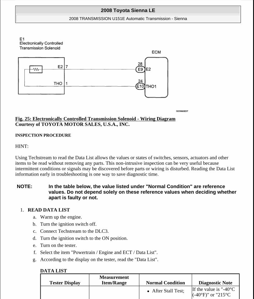
Fig. 25: Electronically Controlled Transmission Solenoid - Wiring Diagram Courtesy of TOYOTA MOTOR SALES, U.S.A., INC.
INSPECTION PROCEDURE
HINT:
Using Techstream to read the Data List allows the values or states of switches, sensors, actuators and other items to be read without removing any parts. This non-intrusive inspection can be very useful because intermittent conditions or signals may be discovered before parts or wiring is disturbed. Reading the Data List information early in troubleshooting is one way to save diagnostic time.
1. READ DATA LIST
a. Warm up the engine.
b. Turn the ignition switch off.
c. Connect Techstream to the DLC3.
d. Turn the ignition switch to the ON position.
e. Turn on the tester.
f. Select the item "Powertrain / Engine and ECT / Data List".
g. According to the display on the tester, read the "Data List".
DATA LIST
NOTE: In the table below, the value listed under "Normal Condition" are reference values. Do not depend solely on these reference values when deciding whether apart is faulty or not.
Tester DisplayMeasurement Item/Range Normal Condition Diagnostic Note
After Stall Test; If the value is "-40°C (-40°F)" or "215°C
2008 Toyota Sienna LE
2008 TRANSMISSION U151E Automatic Transmission - Sienna
Microsoft
Wednesday, August 12, 2009 2:03:23 PM Page 64 © 2005 Mitchell Repair Information Company, LLC.

HINT:
When DTC P0712 is output and Techstream output is 150°C (302°F), there is a short circuit.
When DTC P0713 is output and Techstream output is -40°C (-40°F), there is an open circuit.
Measure the resistance between terminal THO1 (THO) and body ground.
TEMPERATURE SPECIFICATION
HINT:
If a circuit related to the ATF temperature sensor become open, P0713 is immediately set (in 0.5 second).
When P0713 is set, P0711 cannot be detected.
It is not necessary to inspect the circuit when P0711 is set.
1. INSPECT TRANSMISSION WIRE (ATF TEMPERATURE SENSOR)
a. Disconnect the transmission wire connector from the transaxle.
b. Measure the resistance according to the value(s) in the table below.
Standard resistance
RESISTANCE SPECIFICATION
HINT:
If the resistance is out of the specified range with either the ATF temperature shown in the table below, the driveability of the vehicle may decrease.
A/T Oil Temperature 1
ATF Temp. Sensor Value/ min.: -40°C (-40°F) max.: 215°C
(419°F)
Approx. 80°C (176°F)
Equal to ambient temperature when cold soak
(419°F)", ATF temp, sensor circuit is opened or shorted.
Temperature Displayed Malfunction-40°C (-40°F) Open circuit
150°C (302°F) or more Short circuit
Tester Connection Specified Condition1 (THO) - 7 (E2) 79 ohms to 156 kohms
1 (THO) - Body ground 10 kohms or higher7 (E2) - Body ground ?
2008 Toyota Sienna LE
2008 TRANSMISSION U151E Automatic Transmission - Sienna
Microsoft
Wednesday, August 12, 2009 2:03:23 PM Page 65 © 2005 Mitchell Repair Information Company, LLC.

Fig. 26: Identifying Transmission Wire Connector Terminals Courtesy of TOYOTA MOTOR SALES, U.S.A., INC.
ATF TEMPERATURE AND RESISTANCE SPECIFICATION
NG: REPAIR OR REPLACE TRANSMISSION WIRE
OK: Go to Next Step
2. CHECK HARNESS AND CONNECTOR (TRANSMISSION WIRE - ECM)
a. Connect the transmission wire connector to the transaxle.
b. Disconnect the ECM connectors.
c. Measure the resistance according to the value(s) in the table below.
Standard resistance
RESISTANCE SPECIFICATION
d. Measure the resistance according to the value(s) in the table below.
ATF Temperature Specified Condition10°C (50°F) 5 to 8 kohms25°C (77°F) 2.5 to 4.5 kohms
110°C (230°F) 0.22 to 0.28 kohms
Tester Connection Specified ConditionE10-24 (THO1) - E9-28 (E2) 79 ohms to 156kohms
2008 Toyota Sienna LE
2008 TRANSMISSION U151E Automatic Transmission - Sienna
Microsoft
Wednesday, August 12, 2009 2:03:23 PM Page 66 © 2005 Mitchell Repair Information Company, LLC.

Fig. 27: Identifying ECM Connectors Courtesy of TOYOTA MOTOR SALES, U.S.A., INC.
Standard resistance (Check for short)
RESISTANCE SPECIFICATION
NG: REPAIR OR REPLACE HARNESS OR CONNECTOR
OK: REPLACE ECM
DTC P0711 TRANSMISSION FLUID TEMPERATURE SENSOR "A" PERFORMANCE
DESCRIPTION
The ATF (Automatic Transmission Fluid) temperature sensor converts the fluid temperature into a resistance value which is input into the ECM.
DTC DETECTION CONDITION AND TROUBLE AREA
Tester Connection Specified ConditionE10-24 (THO1) - Body ground
10 kohms or higherE9-2S (E2) - Body ground
DTC No. DTC Detection Condition Trouble Area
P0711
A. Both (a) and (b) are detected: (2-trip detection logic)
a. Intake air and engine coolant temperatures are more than -10°C (14°F) at engine start
b. After normal driving for over 19 min. and 9 km (6 mile) or more, ATF temp, is less than 20°C (68°F)
B. When engine coolant temp, is
Transmission wire (ATF temperature sensor)
2008 Toyota Sienna LE
2008 TRANSMISSION U151E Automatic Transmission - Sienna
Microsoft
Wednesday, August 12, 2009 2:03:23 PM Page 67 © 2005 Mitchell Repair Information Company, LLC.

MONITOR DESCRIPTION
The ATF temperature sensor converts the ATF temperature to an electrical resistance value. Based on the resistance, the ECM determines the ATF temperature and detects an open or short in the ATF temperature circuit or a fault in the ATF temperature sensor.
After running the vehicle for a certain period, the ATF temperature should increase. If the ATF temperature is below 20°C (68°F) after running the vehicle for a certain period, the ECM interprets this as a fault, and turns on the MIL.
When the ATF temperature is 110°C (230°F) or more after 17 minutes of engine cold start, the ECM also determines this as a fault, turns on the MIL, and stores the DTC.
MONITOR STRATEGY
MONITOR STRATEGY
TYPICAL ENABLING CONDITIONS
All:
TYPICAL ENABLING CONDITIONS
Condition (A):
TYPICAL ENABLING CONDITIONS
less than 35°C (95°F) at engine start, the ATF temp, is 110°C (230°F) or more after 17 min. of engine start (2-trip detection logic).
Related DTCs P0711: ATF temperature sensor/Rationality checkRequired sensors/Components ATF temperature sensor (TFT sensor)
Frequency of operation Continuous
Duration3 sec.: Condition (A), (B), (C) Continuous.: Condition (D)
MIL operation 2 driving cyclesSequence of operation None
The monitor will run whenever this DTC is not present.
None
TFT sensor circuit Not circuit malfunctionECT sensor circuit Not circuit malfunctionIAT sensor circuit Not circuit malfunctionETCS Not circuit malfunction
2008 Toyota Sienna LE
2008 TRANSMISSION U151E Automatic Transmission - Sienna
Microsoft
Wednesday, August 12, 2009 2:03:23 PM Page 68 © 2005 Mitchell Repair Information Company, LLC.

Condition (B):
TYPICAL ENABLING CONDITIONS
Condition (C):
TYPICAL ENABLING CONDITIONS
Condition (D):
TYPICAL ENABLING CONDITIONS
Condition (E):
TYPICAL ENABLING CONDITIONS
TYPICAL MALFUNCTION THRESHOLDS
Time after engine start 18 min. and 20 sec.Accululated driving time 4 min. and 10 sec.Driving distance after engine start 9 km (5.6 mile) or moreIAT (Intake air temperature) (12 sec. after starting engine)
-10°C (14°F) or more
ECT (12 sec. after starting engine) -10°C (14°F) or moreOpen Air temp (not ECM initial value) -10°C (14°F) or moreTHO (12 sec. after starting engine) -10°C (14°F) or more
Time after engine start 18 min. and 20 sec.Accululated driving time 4 min. and 10 sec.Driving distance after engine start 9 km (5.6 mile) or moreIAT (Intake air temperature) (12 sec. after starting engine)
-10°C (14°F) or more
ECT (12 sec. after starting engine) -10°C (14°F) or more
Time after engine start 30 min.Accululated driving time 6 min. and 40 sec.Driving distance after engine start 15 km (9.3 mile) or moreIAT (Intake air temperature) (12 sec. after starting engine)
-15°C (5°F) or more
ECT (12 sec. after starting engine) -15°C (5°F) or more
Time after engine start 40 min.Accumulated driving time 9 min. and 10 sec.Driving distance after engine start 20 km (124 mile) or more
ECT (12 sec. after engine start) Less than 35°C (95°F)
2008 Toyota Sienna LE
2008 TRANSMISSION U151E Automatic Transmission - Sienna
Microsoft
Wednesday, August 12, 2009 2:03:23 PM Page 69 © 2005 Mitchell Repair Information Company, LLC.

Condition (A), (B), (C), (D):
TYPICAL MALFUNCTION THRESHOLDS
Condition (E):
TYPICAL MALFUNCTION THRESHOLDS
COMPONENT OPERATING RANGE
COMPONENT OPERATING RANGE
WIRING DIAGRAM
Fig. 28: Electronically Controlled Transmission Solenoid - Wiring Diagram Courtesy of TOYOTA MOTOR SALES, U.S.A., INC.
INSPECTION PROCEDURE
HINT:
Using Techstream to read the Data List allows the values or states of switches, sensors, actuators and other items to be read without removing any parts. This non-intrusive inspection can be very useful because intermittent conditions or signals may be discovered before parts or wiring is disturbed. Reading the Data List information early in troubleshooting is one way to save diagnostic time.
ATF temperature sensor Less than 20°C (68°F)
ATF temperature sensor 110°C (230°F) or more
ATF temperature sensor Atmospheric temperature to approx. 130°C (266°F)
NOTE: In the table below, the value listed under "Normal Condition" are reference values. Do not depend solely on these reference values when deciding whether
2008 Toyota Sienna LE
2008 TRANSMISSION U151E Automatic Transmission - Sienna
Microsoft
Wednesday, August 12, 2009 2:03:23 PM Page 70 © 2005 Mitchell Repair Information Company, LLC.

1. READ DATA LIST
a. Warm up the engine.
b. Turn the ignition switch off.
c. Connect Techstream to the DLC3.
d. Turn the ignition switch to the ON position.
e. Turn on the tester.
f. Select the item "Powertrain / Engine and ECT / Data List".
g. According to the display on the tester, read the "Data List".
DATA LIST
HINT.
When DTC P0712 is output and Techstream output is 150°C (302°F), there is a short circuit.
When DTC P0713 is output and Techstream output is -40°C (-40°F), there is an open circuit.
Measure the resistance between terminal THO1 (THO) and body ground.
TEMPERATURE SPECIFICATION
HINT:
If a circuit related to the ATF temperature sensor becomes open, P0713 is immediately set (in 0.5 second).
When P0713 is set, P0711 cannot be detected.
It is not necessary to inspect the circuit when P0711 is set.
apart is faulty or not.
Tester DisplayMeasurement Item/Range Normal Condition Diagnostic Note
A/T Oil Tempature 1
ATF Temp. Sensor Value/ min.: -40°C (-40°F) max.: 215°C
(419°F)
After Stall Test; Approx. 80°C (176°F)
Equal to ambient temperature when cold soak
If the value is "-40°C (-40°F)" or "215°C (419°F)", ATF temp, sensor circuit is opened or shorted.
Temperature Displayed Malfunction-40°C (-40°F) Open circuit
150°C (302°F) or more Short circuit
2008 Toyota Sienna LE
2008 TRANSMISSION U151E Automatic Transmission - Sienna
Microsoft
Wednesday, August 12, 2009 2:03:23 PM Page 71 © 2005 Mitchell Repair Information Company, LLC.

1. CHECK OTHER DTCS OUTPUT (IN ADDITION TO DTC P0711)
a. Connect Techstream to the DLC3.
b. Turn the ignition switch to the ON position and push the Techstream main switch ON.
c. When you use Techstream:
Select the item "Powertrain / Engine and ECT / Trouble Codes".
d. Read the DTCs using Techstream.
Result
RESULT REFERENCE
HINT:
If any other codes besides "P0711" are output, perform troubleshooting for those DTCs first.
B: Go to DTC CHART
A: Go to Next Step
2. CHECK TRANSMISSION FLUID LEVEL
OK: Automatic transmission fluid level is correct.
NG: ADD FLUID
OK: REPLACE TRANSMISSION WIRE (ATF TEMPERATURE SENSOR)
DTC P0717 TURBINE SPEED SENSOR CIRCUIT NO SIGNAL
DESCRIPTION
This sensor detects the rotation speed of the input turbine. By comparing the input turbine speed signal (NT) with the counter gear speed sensor signal (NC), the ECM detects the shift timing of the gears and appropriately controls the engine torque and hydraulic pressure according to various conditions. Thus, providing smooth gear shift.
DTC DETECTION CONDITION AND TROUBLE AREA
Result Proceed toP0711 A
P0711 and other DTCs B
DTC No. DTC Detection Condition Trouble AreaECM detects conditions (a), (b) and (c) continuously for 5 sec. or more:
Open or short in transmission
2008 Toyota Sienna LE
2008 TRANSMISSION U151E Automatic Transmission - Sienna
Microsoft
Wednesday, August 12, 2009 2:03:23 PM Page 72 © 2005 Mitchell Repair Information Company, LLC.

Reference (Using an oscilloscope):
Check the waveform between terminals NT+ and NT- of the ECM connector.
Fig. 29: Waveform Graph Courtesy of TOYOTA MOTOR SALES, U.S.A., INC.
Standard: Refer to the illustration.
WAVEFORM REFERENCE
MONITOR DESCRIPTION
The NT terminal of the ECM detects a revolution signal from the speed sensor (NT) (input RPM). The ECM calculates a gearshift comparing the speed sensor (NT) with the speed sensor (NC).
While the vehicle is operating in 2nd, 3rd, 4th or 5th gear in the shift position of D, if the input shaft revolution is less than 300 rpm *1 although the output shaft revolution is more than 1,000 rpm *2 , the ECM detects the trouble, illuminates the MIL and stores the DTC.
*1: Pulse is not output or is irregularly output.
*2: The vehicle speed is 50 km/h (31 mph) or more.
P0717
(1-trip detection logic)
a. Vehicle speed: 50 km/h (31 mph) or more
b. Park/neutral position switch (NSW (STAR) and R) is OFF
c. Speed sensor (NT): less than 300 rpm
revolution sensor NT (speed sensor NT) circuit
Transmission revolution sensor NT (speed sensor NT)
ECM
Automatic transaxle assembly
Terminal NT+ - NT-Tool setting 5 V/DIV., 0.5 ms./DIV.Vehicle condition Vehicle speed 20 km/h (12 mph)
2008 Toyota Sienna LE
2008 TRANSMISSION U151E Automatic Transmission - Sienna
Microsoft
Wednesday, August 12, 2009 2:03:23 PM Page 73 © 2005 Mitchell Repair Information Company, LLC.

MONITOR STRATEGY
MONITOR STRATEGY
TYPICAL ENABLING CONDITIONS
TYPICAL ENABLING CONDITIONS
TYPICAL MALFUNCTION THRESHOLDS
TYPICAL MALFUNCTION THRESHOLDS
COMPONENT OPERATING RANGE
COMPONENT OPERATING RANGE
WIRING DIAGRAM
Related DTCs P0717: Speed sensor (NT)/Verify pulse inputRequired sensors/Components Speed sensor (NT), Speed sensor (NC)
Frequency of operation ContinuousDuration 5 sec.
MIL operation ImmediateSequence of operation None
The monitor will run whenever this DTC is not present.
P0500 (VSS) P0748, P0778, P0798 (Shift solenoid valve (range))
Shift change Shift change is completed and before starting next shift change operation
ECM selected gear 3rd, 4thOutput shaft rpm 1,000 rpm or moreNSW (STAR) switch OFFR switch OFFL switch OFFEngine RunningIgnition switch ONStarter OFF
Sensor signal rpm Less than 300 rpm
Speed sensor (NT) Turbine speed is equal to engine speed with lock-up ON
2008 Toyota Sienna LE
2008 TRANSMISSION U151E Automatic Transmission - Sienna
Microsoft
Wednesday, August 12, 2009 2:03:23 PM Page 74 © 2005 Mitchell Repair Information Company, LLC.
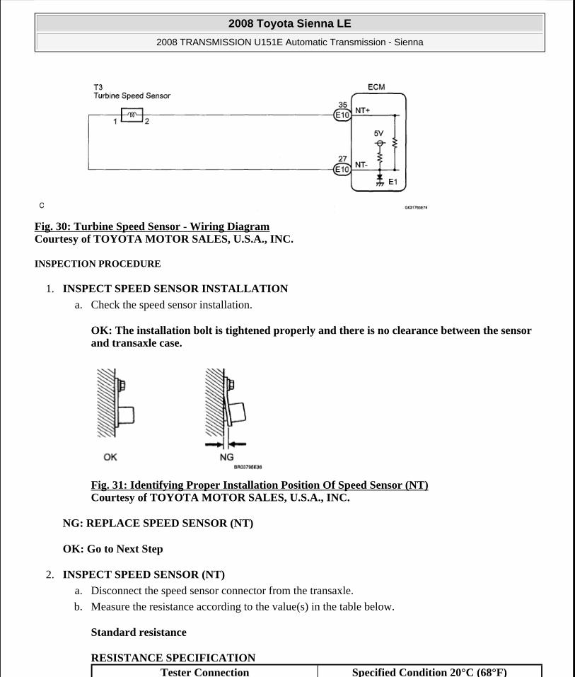
Fig. 30: Turbine Speed Sensor - Wiring Diagram Courtesy of TOYOTA MOTOR SALES, U.S.A., INC.
INSPECTION PROCEDURE
1. INSPECT SPEED SENSOR INSTALLATION
a. Check the speed sensor installation.
OK: The installation bolt is tightened properly and there is no clearance between the sensor and transaxle case.
Fig. 31: Identifying Proper Installation Position Of Speed Sensor (NT) Courtesy of TOYOTA MOTOR SALES, U.S.A., INC.
NG: REPLACE SPEED SENSOR (NT)
OK: Go to Next Step
2. INSPECT SPEED SENSOR (NT)
a. Disconnect the speed sensor connector from the transaxle.
b. Measure the resistance according to the value(s) in the table below.
Standard resistance
RESISTANCE SPECIFICATION Tester Connection Specified Condition 20°C (68°F)
2008 Toyota Sienna LE
2008 TRANSMISSION U151E Automatic Transmission - Sienna
Microsoft
Wednesday, August 12, 2009 2:03:23 PM Page 75 © 2005 Mitchell Repair Information Company, LLC.

Fig. 32: Identifying Speed Sensor Connector Terminals (NT) Courtesy of TOYOTA MOTOR SALES, U.S.A., INC.
NG: REPLACE SPEED SENSOR (NT)
OK: Go to Next Step
3. CHECK HARNESS AND CONNECTOR (SPEED SENSOR - ECM)
a. Connect the speed sensor connector.
b. Disconnect the ECM connector.
c. Measure the resistance according to the value(s) in the table below.
Standard resistance
RESISTANCE SPECIFICATION
d. Measure the resistance according to the value(s) in the table below.
1-2 560 to 680 ohms
Tester Connection Specified Condition 20°C (68°F)E10-35 (NT+) - E10-27 (NT-) 560 to 680 ohms
2008 Toyota Sienna LE
2008 TRANSMISSION U151E Automatic Transmission - Sienna
Microsoft
Wednesday, August 12, 2009 2:03:23 PM Page 76 © 2005 Mitchell Repair Information Company, LLC.

Fig. 33: Disconnecting ECM Connector Courtesy of TOYOTA MOTOR SALES, U.S.A., INC.
Standard resistance (Check for short)
RESISTANCE SPECIFICATION
NG: REPAIR OR REPLACE HARNESS OR CONNECTOR
OK: REPLACE ECM
DTC P0724 BRAKE SWITCH "B" CIRCUIT HIGH
DESCRIPTION
The purpose of this circuit is to prevent the engine from stalling while driving in lock-up condition when brakes are suddenly applied.
When the brake pedal is depressed, this switch sends a signals to the ECM. Then the ECM cancels the operation of the lock-up clutch while braking is in progress.
DTC DETECTION CONDITION AND TROUBLE AREA
MONITOR DESCRIPTION
This DTC indicates that the stop light switch remains on. When the stop light switch remains ON during "stop
Tester Connection Specified ConditionE10-35 (NT+) - Body ground
10 kohms or higherE10-27 (NT-) - Body ground
DTC No. DTC Detection Condition Trouble Area
P0724
The stop light switch remains ON even when the vehicle is driven in a STOP (less than 3 km/h (2 mph) and GO (30 km/h (19 mph) or more) fashion 5 times. (2-trip detection logic).
Short in stop light switch circuit
Stop light switch
ECM
2008 Toyota Sienna LE
2008 TRANSMISSION U151E Automatic Transmission - Sienna
Microsoft
Wednesday, August 12, 2009 2:03:23 PM Page 77 © 2005 Mitchell Repair Information Company, LLC.

and go" driving, the ECM interprets this as a fault in the stop light switch and the MIL comes on and the ECM stores the DTC. The vehicle must stop (less than 3 km/h (2 mph)) and go (30 km/h (19 mph) or more) 5 times for two driving cycles in order to detect a malfunction.
MONITOR STRATEGY
MONITOR STRATEGY
TYPICAL ENABLING CONDITIONS
TYPICAL ENABLING CONDITIONS
TYPICAL MALFUNCTION THRESHOLDS
TYPICAL MALFUNCTION THRESHOLDS
WIRING DIAGRAM
Related DTCs P0724: Stop light switch/RationalityRequired sensors/Components Stop light switch, Vehicle speed sensor
Frequency of operation ContinuousDuration GO and STOP 5 times
MIL operation 2 driving cyclesSequence of operation None
The monitor will run whenever this DTC is not present.
None
Ignition switch ONStarter OFFBattery voltage 8 V or moreGO (Vehicle speed is 30 km/h (18.63 mph) or more) OnceSTOP (Vehicle speed is less than 3 km/h (1.86 mph))
Once
Brake switch Remain ON during GO and STOP 5 times
2008 Toyota Sienna LE
2008 TRANSMISSION U151E Automatic Transmission - Sienna
Microsoft
Wednesday, August 12, 2009 2:03:23 PM Page 78 © 2005 Mitchell Repair Information Company, LLC.

Fig. 34: Stop Light Switch - Wiring Diagram Courtesy of TOYOTA MOTOR SALES, U.S.A., INC.
INSPECTION PROCEDURE
1. READ VALUE OF DATA LIST
HINT:
Using Techstream to read the Data List allows the values or states of switches, sensors, actuators and other items to be read without removing any parts. This non-intrusive inspection can be very useful because intermittent conditions or signals may be discovered before parts or wiring is disturbed. Reading the Data List information early in troubleshooting is one way to save diagnostic time.
a. Warm up the engine.
b. Turn the ignition switch off.
c. Connect Techstream to the DLC3.
d. Turn the ignition switch to the ON position.
e. Turn on the tester.
f. Select the item "Powertrain / Engine and ECT / Data List".
g. According to the display on the tester, read the "Data List".
DATA LIST Tester Display Measurement Item/Range Normal Condition
2008 Toyota Sienna LE
2008 TRANSMISSION U151E Automatic Transmission - Sienna
Microsoft
Wednesday, August 12, 2009 2:03:24 PM Page 79 © 2005 Mitchell Repair Information Company, LLC.

Result
RESULT REFERENCE
B: Go to step 3
A: Go to Next Step
2. INSPECT STOP LIGHT SWITCH ASSEMBLY
a. Remove the stop light switch assembly.
b. Measure the resistance according to the value(s) in the table below.
Standard resistance
RESISTANCE SPECIFICATION
Fig. 35: Inspecting Stop Light Switch Assembly
Stop Light SwitchStop light switch Status/ ON or
OFF
Brake Pedal is depressed: ON
Brake Pedal is released: OFF
NOTE: In the table below, the value listed under "Normal Condition" are reference values. Do not depend solely on these reference values when deciding whether apart is faulty or not.
Result Proceed toNG AOK B
Switch position Tester Connection Specified ConditionSwitch pin free 1-2 Below 1 ohms
Switch pin pushed in ? 10 kohms or higherSwitch pin free 3-4 10 kohms or higher
Switch pin pushed in ? Below 1 ohms
2008 Toyota Sienna LE
2008 TRANSMISSION U151E Automatic Transmission - Sienna
Microsoft
Wednesday, August 12, 2009 2:03:24 PM Page 80 © 2005 Mitchell Repair Information Company, LLC.
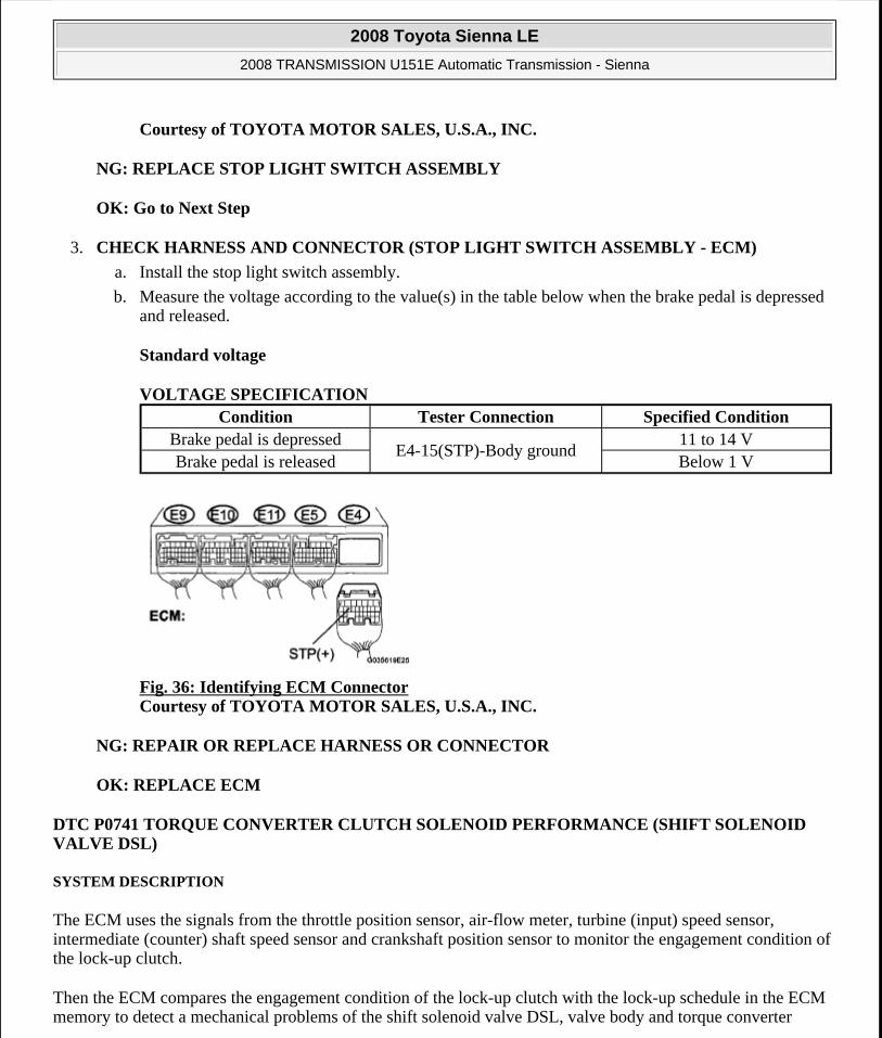
Courtesy of TOYOTA MOTOR SALES, U.S.A., INC.
NG: REPLACE STOP LIGHT SWITCH ASSEMBLY
OK: Go to Next Step
3. CHECK HARNESS AND CONNECTOR (STOP LIGHT SWITCH ASSEMBLY - ECM)
a. Install the stop light switch assembly.
b. Measure the voltage according to the value(s) in the table below when the brake pedal is depressed and released.
Standard voltage
VOLTAGE SPECIFICATION
Fig. 36: Identifying ECM Connector Courtesy of TOYOTA MOTOR SALES, U.S.A., INC.
NG: REPAIR OR REPLACE HARNESS OR CONNECTOR
OK: REPLACE ECM
DTC P0741 TORQUE CONVERTER CLUTCH SOLENOID PERFORMANCE (SHIFT SOLENOID VALVE DSL)
SYSTEM DESCRIPTION
The ECM uses the signals from the throttle position sensor, air-flow meter, turbine (input) speed sensor, intermediate (counter) shaft speed sensor and crankshaft position sensor to monitor the engagement condition of the lock-up clutch.
Then the ECM compares the engagement condition of the lock-up clutch with the lock-up schedule in the ECM memory to detect a mechanical problems of the shift solenoid valve DSL, valve body and torque converter
Condition Tester Connection Specified ConditionBrake pedal is depressed
E4-15(STP)-Body ground11 to 14 V
Brake pedal is released Below 1 V
2008 Toyota Sienna LE
2008 TRANSMISSION U151E Automatic Transmission - Sienna
Microsoft
Wednesday, August 12, 2009 2:03:24 PM Page 81 © 2005 Mitchell Repair Information Company, LLC.
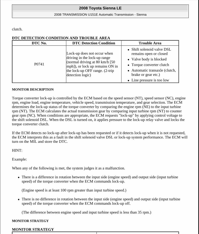
clutch.
DTC DETECTION CONDITION AND TROUBLE AREA
MONITOR DESCRIPTION
Torque converter lock-up is controlled by the ECM based on the speed sensor (NT), speed sensor (NC), engine rpm, engine load, engine temperature, vehicle speed, transmission temperature, and gear selection. The ECM determines the lock-up status of the torque converter by comparing the engine rpm (NE) to the input turbine rpm (NT). The ECM calculates the actual transmission gear by comparing input turbine rpm (NT) to counter gear rpm (NC). When conditions are appropriate, the ECM requests "lock-up" by applying control voltage to the shift solenoid DSL. When the DSL is turned on, it applies pressure to the lock-up relay valve and locks the torque converter clutch.
If the ECM detects no lock-up after lock-up has been requested or if it detects lock-up when it is not requested, the ECM interprets this as a fault in the shift solenoid valve DSL or lock-up system performance. The ECM will turn on the MIL and store the DTC.
HINT:
Example:
When any of the following is met, the system judges it as a malfunction.
There is a difference in rotation between the input side (engine speed) and output side (input turbine speed) of the torque converter when the ECM commands lock-up.
(Engine speed is at least 100 rpm greater than input turbine speed.)
There is no difference in rotation between the input side (engine speed) and output side (input turbine speed) of the torque converter when the ECM commands lock-up off.
(The difference between engine speed and input turbine speed is less than 35 rpm.)
MONITOR STRATEGY
MONITOR STRATEGY
DTC No. DTC Detection Condition Trouble Area
P0741
Lock-up does not occur when driving in the lock-up range (normal driving at 80 km/h [50 mph]), or lock up remains ON in the lock-up OFF range. (2-trip detection logic)
Shift solenoid valve DSL remains open or closed
Valve body is blocked
Torque converter clutch
Automatic transaxle (clutch, brake or gear etc.)
Line pressure is too low
2008 Toyota Sienna LE
2008 TRANSMISSION U151E Automatic Transmission - Sienna
Microsoft
Wednesday, August 12, 2009 2:03:24 PM Page 82 © 2005 Mitchell Repair Information Company, LLC.

TYPICAL ENABLING CONDITIONS
All:
TYPICAL ENABLING CONDITIONS
OFF malfunction (A):
Related DTCsP0741: Shift solenoid valve DSL/OFF malfunction Shift solenoid valve DSL/ON malfunction
Required sensors/Components
Shift solenoid valve DSL, Speed sensor (NT), Speed sensor (NC), Crankshaft position sensor (NE), Throttle position sensor (VPA1), Mass air flow sensor (MAF), Transmission temperature sensor (THO1), Engine coolant temperature sensor (ECT)
Frequency of operation Continuous
Duration
OFF malfunction (A) Continuous. OFF malfunction (B) 1 sec. OFF malfunction (C) 3.5 sec. ON malfunction 1.8 sec.
MIL operation 2 driving cyclesSequence of operation None
The monitor will run whenever this DTC is not present.
P0115-P0118 (ECT sensor) P0125 (Insufficient ECT for closed loop) P0500 (VSS)
P0748, P0778, P0798 (Shift solenoid valve (range))ECT (Engine coolant temperature) 10°C (50°F) or moreTransmission range "D"TFT (Transmission fluid temperature) -20°C (-4°F) or moreTFT sensor circuit Not circuit malfunctionECT sensor circuit Not circuit malfunctionTurbine speed sensor circuit Not circuit malfunctionIntermediate shaft speed sensor circuit Not circuit malfunctionOutput speed sensor circuit Not circuit malfunctionShift solenoid valve SL1 circuit Not circuit malfunctionShift solenoid valve SL2 circuit Not circuit malfunctionShift solenoid valve SL3 circuit Not circuit malfunctionShift solenoid valve S4 circuit Not circuit malfunctionShift solenoid valve SR circuit Not circuit malfunctionShift solenoid valve DSL circuit Not circuit malfunctionElectronic throttle system Not circuit malfunction
2008 Toyota Sienna LE
2008 TRANSMISSION U151E Automatic Transmission - Sienna
Microsoft
Wednesday, August 12, 2009 2:03:24 PM Page 83 © 2005 Mitchell Repair Information Company, LLC.

TYPICAL ENABLING CONDITIONS
OFF malfunction (B):
TYPICAL ENABLING CONDITIONS
OFF malfunction (C):
TYPICAL ENABLING CONDITIONS
ON malfunction:
TYPICAL ENABLING CONDITIONS
TYPICAL MALFUNCTION THRESHOLDS
Either of the following conditions is met: OFF malfunction or ON malfunction OFF malfunction:
TYPICAL MALFUNCTION THRESHOLDS
ON malfunction:
TYPICAL MALFUNCTION THRESHOLDS
INSPECTION PROCEDURE
HINT:
Using Techstream to perform Active Test allows relays, VSVs, actuators and other items to be operated without
ECM selected gear 3rdThrottle valve opening angle 4.5% or more at engine speed gear 1,900 rpm
(varies with engine speed)
ECM selected gear 5thVehicle speed 10 km/h (6.2 mph) or more
ECM lock-up command ONECM selected gear 3rd, 4th or 5thVehicle speed 25 km/h (15.5 mph) or more
ECM lock-up command OFFECM selected gear 3rd, 4th or 5thThrottle valve opening angle 7% or moreVehicle speed 25 to 60 km/h (15.5 to 37.3 mph)
Engine Speed - Input (turbine) speed 100 rpm or more
Difference between engine speed and input (turbine) speed
Less than 35 rpm
2008 Toyota Sienna LE
2008 TRANSMISSION U151E Automatic Transmission - Sienna
Microsoft
Wednesday, August 12, 2009 2:03:24 PM Page 84 © 2005 Mitchell Repair Information Company, LLC.

removing any parts. This non-intrusive functional inspection can be very useful because intermittent operation may be discovered before parts or wiring is disturbed. Performing Active Test early in troubleshooting is one way to save diagnostic time. Data List information can be displayed while performing Active Test.
1. PERFORM ACTIVE TEST
a. Warm up the engine.
b. Turn the ignition switch off.
c. Connect Techstream to the DLC3.
d. Turn the ignition switch to the ON position.
e. Turn on the tester.
f. Select the item "Powertrain / Engine and ECT / Active Test".
g. According to the display on the tester, perform the "Active Test".
ACTIVE TEST DETAIL
HINT:
This test can be conducted when the vehicle speed is 60 km/h (37 mph) or more.
This test can be conducted in the 5th gear.
h. Lightly depress the accelerator pedal and check that the engine speed does not change abruptly.
HINT:
When changing the accelerator pedal opening angle while driving, if the engine speed does not change, lock-up is on.
Slowly release, but not fully, the accelerator pedal in order to decelerate. (Fully releasing the pedal will close the throttle valve and lock-up may be turned off.)
Tester Display Test Part Control Range Diagnostic Note
Activate the Lock Up
[Test Details] Control the shift solenoid DSL to set the automatic transaxle to the lock-up condition. [Vehicle Condition]
Throttle valve opening angle: Less than 35 %
Vehicle Speed: 60 km/h (37 mph) or more, and 5th gear
ON/OFFPossible to check the
DSL operation.
2008 Toyota Sienna LE
2008 TRANSMISSION U151E Automatic Transmission - Sienna
Microsoft
Wednesday, August 12, 2009 2:03:24 PM Page 85 © 2005 Mitchell Repair Information Company, LLC.

Fig. 37: Accelerator Pedal Opening Angle Graph Courtesy of TOYOTA MOTOR SALES, U.S.A., INC.
1. CHECK OTHER DTCS OUTPUT (IN ADDITION TO DTC P0741)
a. Connect Techstream to the DLC3.
b. Turn the ignition switch to the ON position and turn the Techstream main switch ON.
c. When you use Techstream:
Select the item "Powertrain / Engine and ECT / Trouble Codes".
d. Read the DTCs using Techstream.
Result
RESULT REFERENCE
HINT:
If any other codes besides "P0741" are output, perform the troubleshooting for those DTCs first.
B: Go to DTC CHART
A: Go to Next Step
2. INSPECT TRANSMISSION WIRE (DSL)
a. Disconnect the transmission wire connector from the transaxle.
b. Measure the resistance according to the value(s) in the table below.
Standard resistance
RESISTANCE SPECIFICATION
Result Proceed toP0741 A
P0741 and other DTCs B
Tester Connection Specified Condition 20°C (68°F)
2008 Toyota Sienna LE
2008 TRANSMISSION U151E Automatic Transmission - Sienna
Microsoft
Wednesday, August 12, 2009 2:03:24 PM Page 86 © 2005 Mitchell Repair Information Company, LLC.

Fig. 38: Identifying Transmission Wire Connector Terminals (DSL) Courtesy of TOYOTA MOTOR SALES, U.S.A., INC.
NG: Go to step 4
OK: Go to step
3. CHECK HARNESS AND CONNECTOR (TRANSMISSION WIRE - ECM)
a. Connect the transmission wire connector.
b. Disconnect the ECM connector.
c. Measure the resistance according to the value(s) in the table below.
Standard resistance
RESISTANCE SPECIFICATION
10 (DSL) - Body ground 11 to 13 ohms
Tester Connection Specified Condition 20°C (68°F)E10-11 (DSL) - Body ground 11 to 13 ohms
2008 Toyota Sienna LE
2008 TRANSMISSION U151E Automatic Transmission - Sienna
Microsoft
Wednesday, August 12, 2009 2:03:24 PM Page 87 © 2005 Mitchell Repair Information Company, LLC.

Fig. 39: Disconnecting ECM ConnectorCourtesy of TOYOTA MOTOR SALES, U.S.A., INC.
NG: REPAIR OR REPLACE HARNESS OR CONNECTOR
OK: Go to Next Step
4. INSPECT SHIFT SOLENOID VALVE DSL
a. Remove the shift solenoid valve DSL.
b. Measure the resistance according to the value(s) in the table below.
Standard resistance
RESISTANCE SPECIFICATION
c. Connect the positive (+) lead to the terminal of the solenoid connector, and the negative (-) lead to the solenoid body.
OK: The solenoid valve makes an operating sound.
Fig. 40: Measuring Resistance Between Shift Solenoid Valve DSL Terminals And Solenoid Body Courtesy of TOYOTA MOTOR SALES, U.S.A., INC.
NG: REPLACE SHIFT SOLENOID VALVE DSL
OK: Go to Next Step
Tester Connection Specified Condition 20°C (68°F)Solenoid Connector (DSL) - Solenoid Body
(DSL)11 to 13 ohms
2008 Toyota Sienna LE
2008 TRANSMISSION U151E Automatic Transmission - Sienna
Microsoft
Wednesday, August 12, 2009 2:03:24 PM Page 88 © 2005 Mitchell Repair Information Company, LLC.
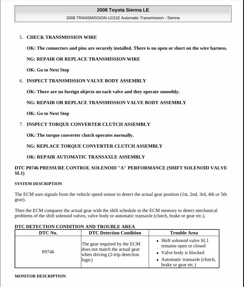
5. CHECK TRANSMISSION WIRE
OK: The connectors and pins are securely installed. There is no open or short on the wire harness.
NG: REPAIR OR REPLACE TRANSMISSION WIRE
OK: Go to Next Step
6. INSPECT TRANSMISSION VALVE BODY ASSEMBLY
OK: There are no foreign objects on each valve and they operate smoothly.
NG: REPAIR OR REPLACE TRANSMISSION VALVE BODY ASSEMBLY
OK: Go to Next Step
7. INSPECT TORQUE CONVERTER CLUTCH ASSEMBLY
OK: The torque converter clutch operates normally.
NG: REPLACE TORQUE CONVERTER CLUTCH ASSEMBLY
OK: REPAIR AUTOMATIC TRANSAXLE ASSEMBLY
DTC P0746 PRESSURE CONTROL SOLENOID "A" PERFORMANCE (SHIFT SOLENOID VALVE SL1)
SYSTEM DESCRIPTION
The ECM uses signals from the vehicle speed sensor to detect the actual gear position (1st, 2nd, 3rd, 4th or 5th gear).
Then the ECM compares the actual gear with the shift schedule in the ECM memory to detect mechanical problems of the shift solenoid valves, valve body or automatic transaxle (clutch, brake or gear etc.).
DTC DETECTION CONDITION AND TROUBLE AREA
MONITOR DESCRIPTION
DTC No. DTC Detection Condition Trouble Area
P0746
The gear required by the ECM does not match the actual gear when driving (2-trip detection logic)
Shift solenoid valve SL1 remains open or closed
Valve body is blocked
Automatic transaxle (clutch, brake or gear etc.)
2008 Toyota Sienna LE
2008 TRANSMISSION U151E Automatic Transmission - Sienna
Microsoft
Wednesday, August 12, 2009 2:03:24 PM Page 89 © 2005 Mitchell Repair Information Company, LLC.

The ECM commands gear shifts by turning the shift solenoid valves "ON/OFF". According to the input shaft revolution, intermediate (counter) shaft revolution and output shaft revolution, the ECM detects the actual gear position (1st, 2nd, 3rd, 4th or 5th gear position). When the gear position commanded by the ECM and the actual gear position are not the same, the ECM illuminates the MIL.
HINT:
Example:
When either condition (a) or (b) is met, the ECM detects a malfunction.
a. The ECM commands the 1st gear, but the actual gear is 2nd.
b. The ECM commands the 2nd gear, but the actual gear is 1st.
MONITOR STRATEGY
MONITOR STRATEGY
TYPICAL ENABLING CONDITIONS
ALL:
TYPICAL ENABLING CONDITIONS
Related DTCsP0746: Shift solenoid valve SL1/OFF malfunction Shift solenoid valve SL1/ON malfunction
Required sensors/Components Shift solenoid valve SL1, Speed sensor (NT), Speed sensor (NC), Crankshaft position sensor (NE)
Frequency of operation ContinuousDuration 0.8 sec.
MIL operation 2 driving cyclesSequence of operation None
The monitor will run whenever this DTC is not present.
P0115 - P0118 (ECT sensor) P0125 (Insufficient ECT for closed loop) P0500 (VSS)
P0748, P0778, P0798 (Shift solenoid valve (range))ECT (Engine coolant temperature) 10°C (50°F) or moreTransmission range "D"TFT (Transmission fluid temperature) -20°C (-4°F) or moreTFT sensor circuit Not circuit malfunctionECT sensor circuit Not circuit malfunctionTurbine speed sensor circuit Not circuit malfunctionIntermediate shaft speed sensor circuit Not circuit malfunctionOutput speed sensor circuit Not circuit malfunction
2008 Toyota Sienna LE
2008 TRANSMISSION U151E Automatic Transmission - Sienna
Microsoft
Wednesday, August 12, 2009 2:03:24 PM Page 90 © 2005 Mitchell Repair Information Company, LLC.

OFF malfunction:
TYPICAL ENABLING CONDITIONS
ON malfunction:
TYPICAL ENABLING CONDITIONS
TYPICAL MALFUNCTION THRESHOLDS
Either of the following conditions is met: OFF malfunction or ON malfunction
OFF malfunction:
2 detections are necessary per driving cycle:
1st detection; temporary flag ON
2nd detection; pending fault code ON
TYPICAL MALFUNCTION THRESHOLDS
ON malfunction:
TYPICAL MALFUNCTION THRESHOLDS
INSPECTION PROCEDURE
Shift solenoid valve SL1 circuit Not circuit malfunctionShift solenoid valve SL2 circuit Not circuit malfunctionShift solenoid valve SL3 circuit Not circuit malfunctionShift solenoid valve S4 circuit Not circuit malfunctionShift solenoid valve SR circuit Not circuit malfunctionShift solenoid valve DSL circuit Not circuit malfunctionElectronic throttle system Not circuit malfunction
ECM selected gear 1stVehicle speed Less than 40 km/h (24.9 mph)Throttle valve opening angle 4.5% or more at engine speed 1,900 rpm (Varies
with engine speed)
ECM selected gear 2ndThrottle valve opening angle 4.5% or more at engine speed 1,900 rpm (Varies
with engine speed)
Input (turbine) speed/Intermediate shaft speed 1.49 to 1.63
Input (turbine) speed/Intermediate shaft speed 2.72 to 2.86
2008 Toyota Sienna LE
2008 TRANSMISSION U151E Automatic Transmission - Sienna
Microsoft
Wednesday, August 12, 2009 2:03:24 PM Page 91 © 2005 Mitchell Repair Information Company, LLC.

HINT:
Using Techstream to perform Active Test allows relays, VSVs, actuators and other items to be operated without removing any parts. This non-intrusive functional inspection can be very useful because intermittent operation may be discovered before parts or wiring is disturbed. Performing Active Test early in troubleshooting is one way to save diagnostic time. Data List information can be displayed while performing Active Test.
1. PERFORM ACTIVE TEST
a. Warm up the engine.
b. Turn the ignition switch off.
c. Connect Techstream to the DLC3.
d. Turn the ignition switch to the ON position.
e. Turn on the tester.
f. Select the item "Powertrain / Engine and ECT / Active Test".
g. According to the display on the tester, perform the "Active Test".
HINT:
While driving, the shift position can be forcibly changed with Techstream.
Comparing the shift position commanded by the Active Test with the actual shift position enables you to confirm the problem (See DATA LIST / ACTIVE TEST ).
ACTIVE TEST DETAIL Tester Display Test Part Control Range Diagnostic Note
Control the Shift Position
[Test Details] Operate the shift solenoid valve and set the each shift position by yourself. [Vehicle Condition]
IDL: ON
Less than 50 km/h (31 mph)
[Others]
Press "-->" button: Shift up
Press "<--" button: Shift down
1st/2nd/3rd/4th/5thPossible to check the operation of the shift
solenoid valves.
2008 Toyota Sienna LE
2008 TRANSMISSION U151E Automatic Transmission - Sienna
Microsoft
Wednesday, August 12, 2009 2:03:24 PM Page 92 © 2005 Mitchell Repair Information Company, LLC.

HINT:
This test can be conducted when the vehicle speed is 50 km/h (31 mph) or less.
The shift position commanded by the ECM is shown in the Data List/Shift Status display on Techstream.
1. CHECK OTHER DTCS OUTPUT (IN ADDITION TO DTC P0746)
a. Connect Techstream to the DLC3.
b. Turn the ignition switch to the ON position and turn the Techstream main switch ON.
c. When you use Techstream:
Select the item "Powertrain / Engine and ECT / Trouble Codes".
d. Read the DTCs using Techstream.
Result
RESULT REFERENCE
HINT:
If any other codes besides "P0746" are output, perform the troubleshooting for those DTCs first.
B: Go to DTC CHART
A: Go to Next Step
2. INSPECT SHIFT SOLENOID VALVE SL1
a. Remove the shift solenoid valve SL1.
b. Measure the resistance according to the value(s) in the table below.
Standard resistance
RESISTANCE SPECIFICATION
c. Connect the positive (+) lead with a 21 W bulb to terminal 2 and the negative (-) lead to terminal 1 of the solenoid valve connector, then check the movement of the valve.
OK: The solenoid makes an operating sound.
Result Proceed toP0746 A
P0746 and other DTCs B
Tester Connection Specified Condition 20°C (68°F)1 -2 5.0 to 5.6 ohms
2008 Toyota Sienna LE
2008 TRANSMISSION U151E Automatic Transmission - Sienna
Microsoft
Wednesday, August 12, 2009 2:03:24 PM Page 93 © 2005 Mitchell Repair Information Company, LLC.

Fig. 41: Measuring Resistance Between Shift Solenoid Valve SL1 Terminals Courtesy of TOYOTA MOTOR SALES, U.S.A., INC.
NG: REPLACE SHIFT SOLENOID VALVE SL1
OK: Go to Next Step
3. INSPECT TRANSMISSION VALVE BODY ASSEMBLY
OK: There are no foreign objects on each valve and they operate smoothly.
NG: REPAIR OR REPLACE TRANSMISSION VALVE BODY ASSEMBLY
OK: Go to Next Step
4. INSPECT TORQUE CONVERTER CLUTCH ASSEMBLY
OK: The torque converter clutch operates normally.
NG: REPLACE TORQUE CONVERTER CLUTCH ASSEMBLY
OK: REPAIR OR REPLACE AUTOMATIC TRANSAXLE ASSEMBLY
DTC P0748 PRESSURE CONTROL SOLENOID "A" ELECTRICAL (SHIFT SOLENOID VALVE SL1)
2008 Toyota Sienna LE
2008 TRANSMISSION U151E Automatic Transmission - Sienna
Microsoft
Wednesday, August 12, 2009 2:03:24 PM Page 94 © 2005 Mitchell Repair Information Company, LLC.

DESCRIPTION
Shifting from 1st to 5th is performed in combination with "ON" and "OFF" operation of the shift solenoid valves SL1, SL2, SL3, S4 and SR which are controlled by the ECM. If an open or short circuit occurs in either of the shift solenoid valves, the ECM controls the remaining normal shift solenoid valves to allow the vehicle to be operated smoothly (Fail safe function).
DTC DETECTION CONDITION AND TROUBLE AREA
MONITOR DESCRIPTION
The ECM commands gear shifts by turning the shift solenoid valves "ON/OFF". When there is an open or short circuit in any shift solenoid valve circuit, the ECM detects the problem and illuminates the MIL and stores the DTC. And the ECM performs the fail-safe function and turns the other normal shift solenoid valves "ON/OFF" (In case of an open or short circuit, the ECM stops sending current to the circuit.) (See DATA LIST / ACTIVE TEST ).
MONITOR STRATEGY
MONITOR STRATEGY
TYPICAL ENABLING CONDITIONS
TYPICAL ENABLING CONDITIONS
DTC No. DTC Detection Condition Trouble Area
P0748
The ECM checks for an open or short in the shift solenoid valve SL1 circuit while driving and shift gears. {1 -trip detection logic)
Output signal duty equals to 100 %.
(NOTE: SL1 output signal duty is less than 100 % under normal condition.)
Open or short in shift solenoid valve SL1 circuit
Shift solenoid valve SL1
ECM
Related DTCs P0748: Shift solenoid valve SL1/Range checkRequired sensors/Components Shift solenoid valve SL1
Frequency of operation ContinuousDuration 1 sec.
MIL operation ImmediateSequence of operation None
The monitor will run whenever this DTC is not present.
None
Battery voltage 10 V or more
2008 Toyota Sienna LE
2008 TRANSMISSION U151E Automatic Transmission - Sienna
Microsoft
Wednesday, August 12, 2009 2:03:24 PM Page 95 © 2005 Mitchell Repair Information Company, LLC.

TYPICAL MALFUNCTION THRESHOLDS
TYPICAL MALFUNCTION THRESHOLDS
COMPONENT OPERATING RANGE
COMPONENT OPERATING RANGE
WIRING DIAGRAM
Fig. 42: Shift Solenoid Valve SL1 - Wiring Diagram Courtesy of TOYOTA MOTOR SALES, U.S.A., INC.
INSPECTION PROCEDURE
1. INSPECT TRANSMISSION WIRE (SL1)
a. Disconnect the transmission wire connector from the transaxle.
b. Measure the resistance according to the value(s) in the table below.
Standard resistance
RESISTANCE SPECIFICATION
c. Measure the resistance according to the value(s) in the table below.
Ignition switch ONStarter OFF
Output signal duty 100%
Output signal duty Less than 100%
Tester Connection Specified Condition 20°C (68°F)6(SL1+)-13(SL1-) 5.0 to 5.6 ohms
2008 Toyota Sienna LE
2008 TRANSMISSION U151E Automatic Transmission - Sienna
Microsoft
Wednesday, August 12, 2009 2:03:24 PM Page 96 © 2005 Mitchell Repair Information Company, LLC.

Standard resistance (Check for short)
RESISTANCE SPECIFICATION
Fig. 43: Identifying Transmission Wire Connector Terminals Courtesy of TOYOTA MOTOR SALES, U.S.A., INC.
NG: Go to step 3
OK: Go to Next Step
2. CHECK HARNESS AND CONNECTOR (TRANSMISSION WIRE - ECM)
a. Connect the transmission wire connector to the transaxle.
b. Disconnect the connector from the ECM.
c. Measure the resistance according to the value(s) in the table below.
Standard resistance
RESISTANCE SPECIFICATION
d. Measure the resistance according to the value(s) in the table below.
Standard resistance (Check for short)
RESISTANCE SPECIFICATION
Tester Connection Specified Condition6 (SL1+) - Body ground 10 kohms or higher13 (SL1-) - Body ground ohms
Tester Connection Specified Condition 20°C (68°F)E10-19 (SL1+) - E10-18 (SL1-) 5.0 to 5.6 ohms
2008 Toyota Sienna LE
2008 TRANSMISSION U151E Automatic Transmission - Sienna
Microsoft
Wednesday, August 12, 2009 2:03:24 PM Page 97 © 2005 Mitchell Repair Information Company, LLC.
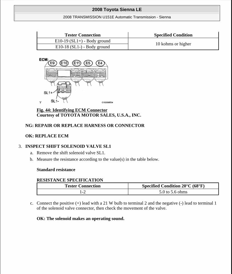
Fig. 44: Identifying ECM Connector Courtesy of TOYOTA MOTOR SALES, U.S.A., INC.
NG: REPAIR OR REPLACE HARNESS OR CONNECTOR
OK: REPLACE ECM
3. INSPECT SHIFT SOLENOID VALVE SL1
a. Remove the shift solenoid valve SL1.
b. Measure the resistance according to the value(s) in the table below.
Standard resistance
RESISTANCE SPECIFICATION
c. Connect the positive (+) lead with a 21 W bulb to terminal 2 and the negative (-) lead to terminal 1 of the solenoid valve connector, then check the movement of the valve.
OK: The solenoid makes an operating sound.
Tester Connection Specified ConditionE10-19 (SL1+) - Body ground
10 kohms or higherE10-18 (SL1-) - Body ground
Tester Connection Specified Condition 20°C (68°F)1-2 5.0 to 5.6 ohms
2008 Toyota Sienna LE
2008 TRANSMISSION U151E Automatic Transmission - Sienna
Microsoft
Wednesday, August 12, 2009 2:03:24 PM Page 98 © 2005 Mitchell Repair Information Company, LLC.

Fig. 45: Measuring Resistance Between Shift Solenoid Valve SL1 Terminals Courtesy of TOYOTA MOTOR SALES, U.S.A., INC.
NG: REPLACE SHIFT SOLENOID VALVE SL1
OK: REPAIR OR REPLACE TRANSMISSION WIRE
DTC P0766 SHIFT SOLENOID "D" PERFORMANCE (SHIFT SOLENOID VALVE S4)
SYSTEM DESCRIPTION
The ECM uses signals from the vehicle speed sensor to detect the actual gear position (1st, 2nd, 3rd, 4th or 5th gear).
Then the ECM compares the actual gear with the shift schedule in the ECM memory to detect mechanical problems of the shift solenoid valves, valve body or automatic transaxle (clutch, brake or gear etc.).
DTC DETECTION CONDITION AND TROUBLE AREA DTC No. DTC Detection Condition Trouble Area
P0766
The gear required by the ECM does not match the actual gear when driving (2-trip detection logic)
Shift solenoid valve S4 remains open or closed
Valve body is blocked
Automatic transaxle (clutch, brake or gear etc.)
2008 Toyota Sienna LE
2008 TRANSMISSION U151E Automatic Transmission - Sienna
Microsoft
Wednesday, August 12, 2009 2:03:24 PM Page 99 © 2005 Mitchell Repair Information Company, LLC.

MONITOR DESCRIPTION
The ECM commands gear shifts by turning the shift solenoid valves "ON/OFF". According to the input shaft revolution, intermediate (counter) shaft revolution and output shaft revolution, the ECM detects the actual gear position (1st, 2nd, 3rd, 4th or 5th gear position). When the gear position commanded by the ECM and the actual gear position are not the same, the ECM illuminates the MIL and stores the DTC.
MONITOR STRATEGY
MONITOR STRATEGY
TYPICAL ENABLING CONDITIONS
All:
TYPICAL ENABLING CONDITIONS
Related DTCsP0766: Shift solenoid valve S4/OFF malfunction Shift solenoid valve S4/ON malfunction
Required sensors/Components Shift solenoid valve S4, Speed sensor (NT), Speed sensor (NC), Crankshaft position sensor (NE)
Frequency of operation Continuous
Duration
OFF malfunction (A) and ON malfunction (B) 1 sec. OFF malfunction (B) 1.2 sec. ON malfunction (A) 0.8 sec.
MIL operation 2 driving cyclesSequence of operation None
The monitor will run whenever this DTC is not present.
P0115 - P0118 (ECT sensor) P0125 (Insufficient ECT for closed loop) P0500 (VSS)
P0748, P0778, P0798 (Shift solenoid valve (range))ECT (Engine coolant temperature) 10°C (50°F) or moreTransmission range "D"TFT (Transmission fluid temperature) -20°C (-4°F) or moreTFT sensor circuit Not circuit malfunctionECT sensor circuit Not circuit malfunctionTurbine speed sensor circuit Not circuit malfunctionIntermediate shaft speed sensor circuit Not circuit malfunctionOutput speed sensor circuit Not circuit malfunctionShift solenoid valve SL1 circuit Not circuit malfunctionShift solenoid valve SL2 circuit Not circuit malfunctionShift solenoid valve SL3 circuit Not circuit malfunction
2008 Toyota Sienna LE
2008 TRANSMISSION U151E Automatic Transmission - Sienna
Microsoft
Wednesday, August 12, 2009 2:03:24 PM Page 100 © 2005 Mitchell Repair Information Company, LLC.
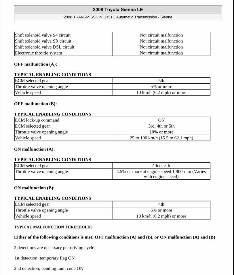
OFF malfunction (A):
TYPICAL ENABLING CONDITIONS
OFF malfunction (B):
TYPICAL ENABLING CONDITIONS
ON malfunction (A):
TYPICAL ENABLING CONDITIONS
ON malfunction (B):
TYPICAL ENABLING CONDITIONS
TYPICAL MALFUNCTION THRESHOLDS
Either of the following conditions is met: OFF malfunction (A) and (B), or ON malfunction (A) and (B)
2 detections are necessary per driving cycle:
1st detection; temporary flag ON
2nd detection; pending fault code ON
Shift solenoid valve S4 circuit Not circuit malfunctionShift solenoid valve SR circuit Not circuit malfunctionShift solenoid valve DSL circuit Not circuit malfunctionElectronic throttle system Not circuit malfunction
ECM selected gear 5thThrottle valve opening angle 5% or moreVehicle speed 10 km/h (6.2 mph) or more
ECM lock-up command ONECM selected gear 3rd, 4th or 5thThrottle valve opening angle 10% or moreVehicle speed 25 to 100 km/h (15.5 to 62.1 mph)
ECM selected gear 4th or 5thThrottle valve opening angle 4.5% or more at engine speed 1,900 rpm (Varies
with engine speed)
ECM selected gear 4thThrottle valve opening angle 5% or moreVehicle speed 10 km/h (6.2 mph) or more
2008 Toyota Sienna LE
2008 TRANSMISSION U151E Automatic Transmission - Sienna
Microsoft
Wednesday, August 12, 2009 2:03:24 PM Page 101 © 2005 Mitchell Repair Information Company, LLC.

OFF malfunction (A):
TYPICAL MALFUNCTION THRESHOLDS
OFF malfunction (B):
TYPICAL MALFUNCTION THRESHOLDS
ON malfunction (A):
TYPICAL MALFUNCTION THRESHOLDS
ON malfunction (B):
TYPICAL MALFUNCTION THRESHOLDS
INSPECTION PROCEDURE
HINT:
Using Techstream to perform Active Test allows relays, VSVs, actuators and other items to be operated without removing any parts. This non-intrusive functional inspection can be very useful because intermittent operation may be discovered before parts or wiring is disturbed. Performing Active Test early in troubleshooting is one way to save diagnostic time. Data List information can be displayed while performing Active Test.
1. PERFORM ACTIVE TEST
a. Warm up the engine.
b. Turn the ignition switch off.
c. Connect Techstream to the DLC3.
d. Turn the ignition switch to the ON position.
e. Turn on the tester.
f. Select the item "Powertrain / Engine and ECT / Active Test".
g. According to the display on the tester, perform the "Active Test".
HINT:
While driving, the shift position can be forcibly changed with Techstream.
Comparing the shift position commanded by the Active Test with the actual shift position enables
Intermediate shaft speed/Output speed 1.44 to 1.58
Difference between engine speed and input (turbine) speed
Less than 35 rpm
Input (turbine) speed/Intermediate shaft speed 0.64 to 0.74
Intermediate shaft speed/Output speed 1.02 to 1.16
2008 Toyota Sienna LE
2008 TRANSMISSION U151E Automatic Transmission - Sienna
Microsoft
Wednesday, August 12, 2009 2:03:24 PM Page 102 © 2005 Mitchell Repair Information Company, LLC.
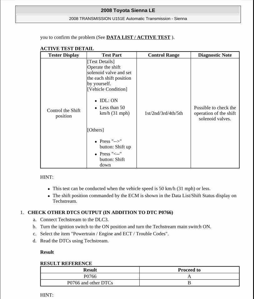
you to confirm the problem (See DATA LIST / ACTIVE TEST ).
ACTIVE TEST DETAIL
HINT:
This test can be conducted when the vehicle speed is 50 km/h (31 mph) or less.
The shift position commanded by the ECM is shown in the Data List/Shift Status display on Techstream.
1. CHECK OTHER DTCS OUTPUT (IN ADDITION TO DTC P0766)
a. Connect Techstream to the DLC3.
b. Turn the ignition switch to the ON position and turn the Techstream main switch ON.
c. Select the item "Powertrain / Engine and ECT / Trouble Codes".
d. Read the DTCs using Techstream.
Result
RESULT REFERENCE
HINT:
Tester Display Test Part Control Range Diagnostic Note
Control the Shift position
[Test Details] Operate the shift solenoid valve and set the each shift position by yourself. [Vehicle Condition]
IDL: ON
Less than 50 km/h (31 mph)
[Others]
Press "-->" button: Shift up
Press "<--" button: Shift down
1st/2nd/3rd/4th/5thPossible to check the operation of the shift
solenoid valves.
Result Proceed toP0766 A
P0766 and other DTCs B
2008 Toyota Sienna LE
2008 TRANSMISSION U151E Automatic Transmission - Sienna
Microsoft
Wednesday, August 12, 2009 2:03:24 PM Page 103 © 2005 Mitchell Repair Information Company, LLC.

If any other codes besides "P0766" are output, perform the troubleshooting for those DTCs first.
B: Go to DTC CHART
A: Go to Next Step
2. INSPECT SHIFT SOLENOID VALVE S4
a. Remove the shift solenoid valve S4.
b. Measure the resistance according to the value(s) in the table below.
Standard resistance
RESISTANCE SPECIFICATION
c. Connect the positive (+) lead to the terminal of the solenoid connector, and the negative (-) lead to the solenoid body.
OK: The solenoid makes an operating sound.
Fig. 46: Measuring Resistance Between Shift Solenoid Valve S4 Terminals And Solenoid Body Courtesy of TOYOTA MOTOR SALES, U.S.A., INC.
NG: REPLACE SHIFT SOLENOID VALVE S4
OK: Go to Next Step
3. INSPECT TRANSMISSION VALVE BODY ASSEMBLY
Tester Connection Specified Condition 20°C (68°F)Solenoid Connector (S4) - Solenoid Body (S4) 11 to 15 ohms
2008 Toyota Sienna LE
2008 TRANSMISSION U151E Automatic Transmission - Sienna
Microsoft
Wednesday, August 12, 2009 2:03:24 PM Page 104 © 2005 Mitchell Repair Information Company, LLC.

OK: There are no foreign objects on each valve and they operate smoothly.
NG: REPAIR OR REPLACE TRANSMISSION VALVE BODY ASSEMBLY
OK: Go to Next Step
4. INSPECT TORQUE CONVERTER CLUTCH ASSEMBLY
OK: The torque converter clutch operates normally.
NG: REPLACE TORQUE CONVERTER CLUTCH ASSEMBLY
OK: REPAIR OR REPLACE AUTOMATIC TRANSAXLE ASSEMBLY
DTC P0771 SHIFT SOLENOID "E" PERFORMANCE (SHIFT SOLENOID VALVE SR)
SYSTEM DESCRIPTION
The ECM uses signals from the vehicle speed sensor to detect the actual gear position (1st, 2nd, 3rd, 4th or 5th gear).
Then the ECM compares the actual gear with the shift schedule in the ECM memory to detect mechanical problems of the shift solenoid valves, valve body or automatic transaxle (clutch, brake or gear etc.).
DTC DETECTION CONDITION AND TROUBLE AREA
MONITOR DESCRIPTION
The ECM commands gear shifts by turning the shift solenoid valves "ON/OFF". According to the input shaft revolution, intermediate (counter) shaft revolution and output shaft revolution, the ECM detects the actual gear position (1st, 2nd, 3rd, 4th or 5th gear position). When the gear position commanded by the ECM and the actual gear position are not the same, the ECM illuminates the MIL and stores the DTC.
MONITOR STRATEGY
MONITOR STRATEGY
DTC No. DTC Detection Condition Trouble Area
P0771
The gear required by the ECM does not match the actual gear when driving (2-trip detection logic)
Shift solenoid valve SR remains open or closed
Valve body is blocked
Automatic transaxle (clutch, brake or gear etc.)
Related DTCs P0771: Shift solenoid valve SR/Rationality check
Required sensors/Components Shift solenoid valve SR, Speed sensor (NT), Speed
2008 Toyota Sienna LE
2008 TRANSMISSION U151E Automatic Transmission - Sienna
Microsoft
Wednesday, August 12, 2009 2:03:24 PM Page 105 © 2005 Mitchell Repair Information Company, LLC.

TYPICAL ENABLING CONDITIONS
All:
TYPICAL ENABLING CONDITIONS
OFF malfunction (A):
TYPICAL ENABLING CONDITIONS
sensor (NC), Crankshaft position sensor (NE)Frequency of operation Continuous
Duration
OFF malfunction (A) 1 sec. OFF malfunction (B) 3.5 sec. ON malfunction (A) Continuous ON malfunction (B) and (C) 0.8 sec.
MIL operation 2 driving cyclesSequence of operation None
The monitor will run whenever this DTC is not present
P0115-P0118 (ECT sensor) P0125 (Insufficient ECT for closed loop) P0500 (VSS)
P0748, P0778, P0798 (Shift solenoid valve (range))ECT (Engine coolant temperature) 10°C (50°F) or moreTransmission range "D"TFT (Transmission fluid temperature) -20°C (-4°F) or moreTFT sensor circuit Not circuit malfunctionECT sensor circuit Not circuit malfunctionTurbine speed sensor circuit Not circuit malfunctionIntermediate shaft speed sensor circuit Not circuit malfunctionOutput speed sensor circuit Not circuit malfunctionShift solenoid valve SL1 circuit Not circuit malfunctionShift solenoid valve SL2 circuit Not circuit malfunctionShift solenoid valve SL3 circuit Not circuit malfunctionShift solenoid valve S4 circuit Not circuit malfunctionShift solenoid valve SR circuit Not circuit malfunctionShift solenoid valve DSL circuit Not circuit malfunctionElectronic throttle system Not circuit malfunction
ECM selected gear 5thThrottle valve opening angle 5% or moreVehicle speed 10 km/h (6.2 mph) or more
2008 Toyota Sienna LE
2008 TRANSMISSION U151E Automatic Transmission - Sienna
Microsoft
Wednesday, August 12, 2009 2:03:24 PM Page 106 © 2005 Mitchell Repair Information Company, LLC.

OFF malfunction (B):
TYPICAL ENABLING CONDITIONS
ON malfunction (A):
TYPICAL ENABLING CONDITIONS
ON malfunction (B):
TYPICAL ENABLING CONDITIONS
ON malfunction (C):
TYPICAL ENABLING CONDITIONS
ON malfunction (D):
TYPICAL ENABLING CONDITIONS
TYPICAL MALFUNCTION THRESHOLDS
Either of the following conditions is met: OFF malfunction (A) and (B), or ON malfunction (A), (B), (C) and (D)
OFF malfunction (A):
TYPICAL MALFUNCTION THRESHOLDS
OFF malfunction (B):
ECM lock-up command ONECM selected gear 3rd, 4th or 5thVehicle speed 25 km/h (15.5 mph) or more
ECM lock-up command OFF
ECM selected gear 1stVehicle speed Less than 40 km/h (24.9 mph)Throttle valve opening angle 4.5% or more at engine speed 1,900 rpm (Varies
with engine speed)
ECM selected gear 3rdThrottle valve opening angle 4.5% or more at engine speed 1,900 rpm (Varies
with engine speed)
Duration time from shift command of ECM 15 sec. or moreECM selected gear 4th or 5th
Intermediate shaft speed/Output speed 1.44 to 1.58
2008 Toyota Sienna LE
2008 TRANSMISSION U151E Automatic Transmission - Sienna
Microsoft
Wednesday, August 12, 2009 2:03:24 PM Page 107 © 2005 Mitchell Repair Information Company, LLC.

TYPICAL MALFUNCTION THRESHOLDS
ON malfunction (A):
TYPICAL MALFUNCTION THRESHOLDS
ON malfunction (B):
TYPICAL MALFUNCTION THRESHOLDS
ON malfunction (C):
TYPICAL MALFUNCTION THRESHOLDS
ON malfunction (D):
TYPICAL MALFUNCTION THRESHOLDS
INSPECTION PROCEDURE
HINT:
Using Techstream to perform Active Test allows relays, VSVs, actuators and other items to be operated without removing any parts. This non-intrusive functional inspection can be very useful because intermittent operation may be discovered before parts or wiring is disturbed. Performing Active Test early in troubleshooting is one way to save diagnostic time. Data List information can be displayed while performing Active Test.
1. PERFORM ACTIVE TEST
a. Warm up the engine.
b. Turn the ignition switch off.
c. Connect Techstream to the DLC3.
d. Turn the ignition switch to the ON position.
e. Turn on the tester.
f. Select the item "Powertrain / Engine and ECT / Active Test".
g. According to the display on the tester, perform the "Active Test".
HINT:
Engine speed - Input (turbine) speed 75 rpm or more
Difference between engine speed and input (turbine) speed
150 rpm or more
Input (turbine) speed/Intermediate shaft speed 0.93 to 1.07
Input (turbine) speed/Intermediate shaft speed 0.93 to 1.07
Input (turbine) speed/Intermediate shaft speed 0.64 to 0.74
2008 Toyota Sienna LE
2008 TRANSMISSION U151E Automatic Transmission - Sienna
Microsoft
Wednesday, August 12, 2009 2:03:24 PM Page 108 © 2005 Mitchell Repair Information Company, LLC.

While driving, the shift position can be forcibly changed with Techstream.
Comparing the shift position commanded by the Active Test with the actual shift position enables you to confirm the problem (See DATA LIST / ACTIVE TEST ).
ACTIVE TEST DETAIL
HINT:
This test can be conducted when the vehicle speed is 50 km/h (31 mph) or less.
The shift position commanded by the ECM is shown in the Data List/Shift Status display on Techstream.
1. CHECK OTHER DTCS OUTPUT (IN ADDITION TO DTC P0771)
a. Connect Techstream to the DLC3.
b. Turn the ignition switch to the ON position and turn the Techstream main switch ON.
c. When you use Techstream:
Select the item "Powertrain / Engine and ECT / Trouble Codes".
d. Read the DTCs using Techstream.
Result
RESULT REFERENCE
Tester Display Test Part Control Range Diagnostic Note
Control the Shift Position
[Test Details] Operate the shift solenoid valve and set the each shift position by yourself. [Vehicle Condition]
IDL: ON
Less than 50 km/h (31 mph)
[Others]
Press "-->" button: Shift up
Press "<--" button: Shift down
1st/2nd/3rd/4th/5thPossible to check the operation of the shift
solenoid valves.
2008 Toyota Sienna LE
2008 TRANSMISSION U151E Automatic Transmission - Sienna
Microsoft
Wednesday, August 12, 2009 2:03:24 PM Page 109 © 2005 Mitchell Repair Information Company, LLC.

HINT:
If any other codes besides "P0771" are output, perform the troubleshooting for those DTCs first.
B: Go to DTC CHART
A: Go to Next Step
2. INSPECT SHIFT SOLENOID VALVE SR
a. Remove the shift solenoid valve SR.
b. Measure the resistance according to the value(s) in the table below.
Standard resistance
RESISTANCE SPECIFICATION
c. Connect positive (+) lead to the terminal of solenoid connector, negative (-) lead to the solenoid body.
OK: The solenoid makes an operating sound.
Fig. 47: Measuring Resistance Between Shift Solenoid Valve SR Terminals And Solenoid Body Courtesy of TOYOTA MOTOR SALES, U.S.A., INC.
Result Proceed toP0771 A
P0771 and other DTCs B
Tester Connection Specified Condition 20°C (68°F)Solenoid Connector (SR) - Solenoid Body (SR) 11 to 15 ohms
2008 Toyota Sienna LE
2008 TRANSMISSION U151E Automatic Transmission - Sienna
Microsoft
Wednesday, August 12, 2009 2:03:24 PM Page 110 © 2005 Mitchell Repair Information Company, LLC.

NG: REPLACE SHIFT SOLENOID VALVE SR
OK: Go to Next Step
3. INSPECT TRANSMISSION VALVE BODY ASSEMBLY
OK: There are no foreign objects on each valve and they operate smoothly.
NG: REPAIR OR REPLACE TRANSMISSION VALVE BODY ASSEMBLY
OK: Go to Next Step
4. INSPECT TORQUE CONVERTER CLUTCH ASSEMBLY
OK: The torque converter clutch operates normally.
NG: REPLACE TORQUE CONVERTER CLUTCH ASSEMBLY
OK: REPAIR OR REPLACE AUTOMATIC TRANSAXLE ASSEMBLY
DTC P0776 PRESSURE CONTROL SOLENOID "B" PERFORMANCE (SHIFT SOLENOID VALVE SL2)
SYSTEM DESCRIPTION
The ECM uses signals from the vehicle speed sensor to detect the actual gear position (1st, 2nd, 3rd, 4th or 5th gear).
Then the ECM compares the actual gear with the shift schedule in the ECM memory to detect mechanical problems of the shift solenoid valves, valve body or automatic transaxle (clutch, brake or gear etc.).
DTC DETECTION CONDITION AND TROUBLE AREA
MONITOR DESCRIPTION
The ECM commands gear shifts by turning the shift solenoid valves "ON/OFF". According to the input shaft revolution, intermediate (counter) shaft revolution and output shaft revolution, the ECM detects the actual gear position (1st, 2nd, 3rd, 4th or 5th gear position). When the gear position commanded by the ECM and the actual gear position are not the same, the ECM illuminates the MIL and stores the DTC.
DTC No. DTC Detection Condition Trouble Area
P0776
The gear required by the ECM does not match the actual gear when driving (2-trip detection logic)
Shift solenoid valve SL2 remains open or closed
Valve body is blocked
Automatic transaxle (clutch, brake or gear etc.)
2008 Toyota Sienna LE
2008 TRANSMISSION U151E Automatic Transmission - Sienna
Microsoft
Wednesday, August 12, 2009 2:03:24 PM Page 111 © 2005 Mitchell Repair Information Company, LLC.
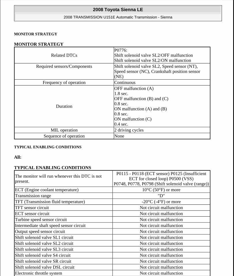
MONITOR STRATEGY
MONITOR STRATEGY
TYPICAL ENABLING CONDITIONS
All:
TYPICAL ENABLING CONDITIONS
Related DTCsP0776: Shift solenoid valve SL2/OFF malfunction Shift solenoid valve SL2/ON malfunction
Required sensors/Components Shift solenoid valve SL2, Speed sensor (NT), Speed sensor (NC), Crankshaft position sensor (NE)
Frequency of operation Continuous
Duration
OFF malfunction (A) 1.8 sec. OFF malfunction (B) and (C) 0.8 sec. ON malfunction (A) and (B) 0.8 sec. ON malfunction (C) 0.4 sec.
MIL operation 2 driving cyclesSequence of operation None
The monitor will run whenever this DTC is not present.
P0115 - P0118 (ECT sensor) P0125 (Insufficient ECT for closed loop) P0500 (VSS)
P0748, P0778, P0798 (Shift solenoid valve (range))ECT (Engine coolant temperature) 10°C (50°F) or moreTransmission range "D"TFT (Transmission fluid temperature) -20°C (-4°F) or moreTFT sensor circuit Not circuit malfunctionECT sensor circuit Not circuit malfunctionTurbine speed sensor circuit Not circuit malfunctionIntermediate shaft speed sensor circuit Not circuit malfunctionOutput speed sensor circuit Not circuit malfunctionShift solenoid valve SL1 circuit Not circuit malfunctionShift solenoid valve SL2 circuit Not circuit malfunctionShift solenoid valve SL3 circuit Not circuit malfunctionShift solenoid valve S4 circuit Not circuit malfunctionShift solenoid valve SR circuit Not circuit malfunctionShift solenoid valve DSL circuit Not circuit malfunctionElectronic throttle system Not circuit malfunction
2008 Toyota Sienna LE
2008 TRANSMISSION U151E Automatic Transmission - Sienna
Microsoft
Wednesday, August 12, 2009 2:03:24 PM Page 112 © 2005 Mitchell Repair Information Company, LLC.

OFF malfunction (A):
TYPICAL ENABLING CONDITIONS
OFF malfunction (B):
TYPICAL ENABLING CONDITIONS
OFF malfunction (C):
TYPICAL ENABLING CONDITIONS
OFF malfunction (D):
TYPICAL ENABLING CONDITIONS
ON malfunction (A):
TYPICAL ENABLING CONDITIONS
ON malfunction (B):
TYPICAL ENABLING CONDITIONS
ECM lock-up command OFFVehicle speed Less than 60 km/h (37.3 mph)Throttle valve opening angle 10% or more
ECM selected gear 1stVehicle speed Less than 40 km/h (24.9 mph)Throttle valve opening angle 4.5% or more at engine speed 1,900 rpm (Varies
with engine speed)
ECM selected gear 3rdThrottle valve opening angle 4.5% or more at engine speed 1,900 rpm (Varies
with engine speed)
ECM selected gear 4th or 5thDuration time from shift command of ECM 15 sec. or more
ECM selected gear 1stVehicle speed Less than 40 km/h (24.9 mph)Throttle valve opening angle 4.5% or more at engine speed 1,900 rpm (Varies
with engine speed)
ECM selected gear 3rdThrottle valve opening angle 5.0% or more at output speed 1,400 rpm (Varies
with engine speed)Malfunction of pressure control solenoid "B" (SL2) Not detected
2008 Toyota Sienna LE
2008 TRANSMISSION U151E Automatic Transmission - Sienna
Microsoft
Wednesday, August 12, 2009 2:03:24 PM Page 113 © 2005 Mitchell Repair Information Company, LLC.

ON malfunction (C):
TYPICAL ENABLING CONDITIONS
TYPICAL MALFUNCTION THRESHOLDS
Either of the following conditions is met: OFF malfunction (A), (B), (C) and (D), or ON malfunction (A), (B) and (C)
OFF malfunction (A):
TYPICAL MALFUNCTION THRESHOLDS
OFF malfunction (B) and (C):
TYPICAL MALFUNCTION THRESHOLDS
OFF malfunction (D):
TYPICAL MALFUNCTION THRESHOLDS
ON malfunction (A):
TYPICAL MALFUNCTION THRESHOLDS
ON malfunction (B):
TYPICAL MALFUNCTION THRESHOLDS
ON malfunction (C):
TYPICAL MALFUNCTION THRESHOLDS
and "C" (SL3)
Throttle valve opening angle 7.0% or more at output speed 1,050 rpm (Varies with engine speed)
Malfunction of pressure control solenoid "B" (SL2) Not detected
Difference between engine speed and input (turbine) speed
Less than 35 rpm
Input (turbine) speed/Intermediate shaft speed 0.93 to 1.07
Input (turbine) speed/Intermediate shaft speed 0.64 to 0.74
Input (turbine) speed/Intermediate shaft speed 2.72 to 2.86
Input (turbine) speed - Intermediate shaft speed 700 rpm or more
Input (turbine) speed - Intermediate shaft speed Less than -500 rpm or 700 rpm or more
2008 Toyota Sienna LE
2008 TRANSMISSION U151E Automatic Transmission - Sienna
Microsoft
Wednesday, August 12, 2009 2:03:24 PM Page 114 © 2005 Mitchell Repair Information Company, LLC.

INSPECTION PROCEDURE
HINT:
Using Techstream to perform Active Test allows relays, VSVs, actuators and other items to be operated without removing any parts. This non-intrusive functional inspection can be very useful because intermittent operation may be discovered before parts or wiring is disturbed. Performing Active Test early in troubleshooting is one way to save diagnostic time. Data List information can be displayed while performing Active Test.
1. PERFORM ACTIVE TEST
a. Warm up the engine.
b. Turn the ignition switch off.
c. Connect Techstream to the DLC3.
d. Turn the ignition switch to the ON position.
e. Turn on the tester.
f. Select the item "Powertrain / Engine and ECt / Active Test".
g. According to the display on the tester, perform the "Active Test".
HINT:
While driving, the shift position can be forcibly changed with Techstream.
Comparing the shift position commanded by the Active Test with the actual shift position enables you to confirm the problem (See DATA LIST / ACTIVE TEST ).
ACTIVE TEST DETAIL Tester Display Test Part Control Range Diagnostic Note
Control the Shift Position
[Test Details] Operate the shift solenoid valve and set the each shift position by yourself. [Vehicle Condition]
IDL: ON
Less than 50 km/h (31 mph)
[Others]
Press "-->" button: Shift up
Press "<--"
1st/2nd/3rd/4th/5thPossible to check the operation of the shift
solenoid valves.
2008 Toyota Sienna LE
2008 TRANSMISSION U151E Automatic Transmission - Sienna
Microsoft
Wednesday, August 12, 2009 2:03:24 PM Page 115 © 2005 Mitchell Repair Information Company, LLC.

HINT:
This test can be conducted when the vehicle speed is 50 km/h (31 mph) or less.
The shift position commanded by the ECM is shown in the Data List/Shift Status display on Techstream.
1. CHECK OTHER DTCS OUTPUT (IN ADDITION TO DTC P0776)
a. Connect Techstream to the DLC3.
b. Turn the ignition switch to the ON position and turn the Techstream main switch ON.
c. When you use Techstream:
Select the item "Powertrain / Engine and ECT / Trouble Codes".
d. Read the DTCs using Techstream.
Result
RESULT REFERENCE
HINT:
If any other codes besides "P0776" are output, perform the troubleshooting for those DTCs first.
B: Go to DTC CHART
A: Go to Next Step
2. INSPECT SHIFT SOLENOID VALVE SL2
a. Remove the shift solenoid valve SL2.
b. Measure the resistance according to the value(s) in the table below.
Standard resistance
RESISTANCE SPECIFICATION
c. Connect the positive (+) lead with a 21 W bulb to terminal 2 and the negative (-) lead to terminal 1
button: Shift down
Result Proceed toP0776 A
P0776 and other DTCs B
Tester Connection Specified Condition 20°C (68°F)1-2 5.0 to 5.6 ohms
2008 Toyota Sienna LE
2008 TRANSMISSION U151E Automatic Transmission - Sienna
Microsoft
Wednesday, August 12, 2009 2:03:24 PM Page 116 © 2005 Mitchell Repair Information Company, LLC.

of the solenoid valve connector, then check the movement of the valve.
OK: The solenoid makes an operating sound.
Fig. 48: Measuring Resistance Between Shift Solenoid Valve SL2 Terminals Courtesy of TOYOTA MOTOR SALES, U.S.A., INC.
NG: REPLACE SHIFT SOLENOID VALVE SL2
OK: Go to Next Step
3. INSPECT TRANSMISSION VALVE BODY ASSEMBLY
OK: There are no foreign objects on each valve and they operate smoothly.
NG: REPAIR OR REPLACE TRANSMISSION VALVE BODY ASSEMBLY
OK: Go to Next Step
4. INSPECT TORQUE CONVERTER CLUTCH ASSEMBLY
OK: The torque converter clutch operates normally.
NG: REPLACE TORQUE CONVERTER CLUTCH ASSEMBLY
OK: REPAIR OR REPLACE AUTOMATIC TRANSAXLE ASSEMBLY
2008 Toyota Sienna LE
2008 TRANSMISSION U151E Automatic Transmission - Sienna
Microsoft
Wednesday, August 12, 2009 2:03:24 PM Page 117 © 2005 Mitchell Repair Information Company, LLC.

DTC P0778 PRESSURE CONTROL SOLENOID "B" ELECTRICAL (SHIFT SOLENOID VALVE SL2)
DESCRIPTION
Shifting from 1st to 5th is performed in combination with "ON" and "OFF" operation of the shift solenoid valves SL1, SL2, SL3, S4 and SR which are controlled by the ECM. If an open or short circuit occurs in either of the shift solenoid valves, the ECM controls the remaining normal shift solenoid valves to allow the vehicle to be operated smoothly (Fail safe function).
DTC DETECTION CONDITION AND TROUBLE AREA
MONITOR DESCRIPTION
The ECM commands gear shifts by turning the shift solenoid valves "ON/OFF". When there is an open or short circuit in any shift solenoid valve circuit, the ECM detects the problem and illuminates the MIL and stores the DTC. And the ECM performs the fail-safe function and turns the other normal shift solenoid valves "ON/OFF" (In case of an open or short circuit, the ECM stops sending current to the circuit.) (See DATA LIST / ACTIVE TEST ).
MONITOR STRATEGY
MONITOR STRATEGY
TYPICAL ENABLING CONDITIONS
TYPICAL ENABLING CONDITIONS
DTC No. DTC Detection Condition Trouble Area
P0778
ECM checks for an open or short circuit in shift solenoid valves SL2 (1-trip detection logic) Hybrid IC for solenoid indicates fail.
Open or short in shift solenoid valve SL2 circuit
Shift solenoid valve SL2
ECM
Related DTCs P0778: Shift solenoid valve SL2/Range checkRequired sensors/Components Shift solenoid valve SL2
Frequency of operation ContinuousDuration 1 sec.
MIL operation ImmediateSequence of operation None
The monitor will run whenever this DTC is not present.
None
Solenoid current cut status Not cutBattery voltage 11 V or moreIgnition switch ONStarter OFF
2008 Toyota Sienna LE
2008 TRANSMISSION U151E Automatic Transmission - Sienna
Microsoft
Wednesday, August 12, 2009 2:03:24 PM Page 118 © 2005 Mitchell Repair Information Company, LLC.

TYPICAL MALFUNCTION THRESHOLDS
TYPICAL MALFUNCTION THRESHOLDS
COMPONENT OPERATING RANGE
COMPONENT OPERATING RANGE
WIRING DIAGRAM
Fig. 49: Shift Solenoid Valve SL2 - Wiring Diagram Courtesy of TOYOTA MOTOR SALES, U.S.A., INC.
INSPECTION PROCEDURE
1. INSPECT TRANSMISSION WIRE (SL2)
a. Disconnect the transmission wire connector from the transaxle.
b. Measure the resistance according to the value(s) in the table below.
Standard resistance
RESISTANCE SPECIFICATION
c. Measure the resistance according to the value(s) in the table below.
OK: Standard resistance (Check for short)
CPU commanded duty ratio to SL2 19% or more
Solenoid status from IC Fail (Open or short)
Output signal duty Less than 100%
Tester Connection Specified Condition 20°C (68°F)5(SL2+)-12(SL2-) 5.0 to 5.6 ohms
2008 Toyota Sienna LE
2008 TRANSMISSION U151E Automatic Transmission - Sienna
Microsoft
Wednesday, August 12, 2009 2:03:24 PM Page 119 © 2005 Mitchell Repair Information Company, LLC.

RESISTANCE SPECIFICATION
Fig. 50: Identifying Transmission Wire Connector Terminals (SL2) Courtesy of TOYOTA MOTOR SALES, U.S.A., INC.
NG: Go to step 3
OK: Go to Next Step
2. CHECK HARNESS AND CONNECTOR (TRANSMISSION WIRE - ECM)
a. Connect the transmission wire connector to the transaxle.
b. Disconnect the connector from the ECM.
c. Measure the resistance according to the value(s) in the table below.
Standard resistance
RESISTANCE SPECIFICATION
d. Measure the resistance according to the value(s) in the table below.
Tester Connection Specified Condition5 (SL2+) - Body ground 10 kohms or higher12 (SL2-)-Body ground ?
Tester Connection Specified Condition 20°C (68°F)E10-15 (SL2+) - E10-14 (SL2-) 5.0 to 5.6 ohms
2008 Toyota Sienna LE
2008 TRANSMISSION U151E Automatic Transmission - Sienna
Microsoft
Wednesday, August 12, 2009 2:03:24 PM Page 120 © 2005 Mitchell Repair Information Company, LLC.

Fig. 51: Identifying ECM Connector Courtesy of TOYOTA MOTOR SALES, U.S.A., INC.
OK: Standard resistance (Check for short)
RESISTANCE SPECIFICATION
NG: REPAIR OR REPLACE HARNESS OR CONNECTOR
OK: REPLACE ECM
3. INSPECT SHIFT SOLENOID VALVE SL2
a. Remove the shift solenoid valve SL2.
b. Measure the resistance according to the value(s) in the table below.
Standard resistance
RESISTANCE SPECIFICATION
c. Connect the positive (+) lead with a 21 W bulb to terminal 2 and the negative (-) lead to terminal 1 of the solenoid valve connector, then check the movement of the valve.
OK: The solenoid makes an operating sound.
Tester Connection Specified ConditionE10-15 (SL2+) - Body ground
10 kohms or higherE10-14 (SL2-) - Body ground
Tester Connection Specified Condition 20°C (68°F)1-2 5.0 to 5.6 ohms
2008 Toyota Sienna LE
2008 TRANSMISSION U151E Automatic Transmission - Sienna
Microsoft
Wednesday, August 12, 2009 2:03:24 PM Page 121 © 2005 Mitchell Repair Information Company, LLC.

Fig. 52: Measuring Resistance Between Shift Solenoid Valve SL2 Terminals Courtesy of TOYOTA MOTOR SALES, U.S.A., INC.
NG: REPLACE SHIFT SOLENOID VALVE SL2
OK: REPAIR OR REPLACE TRANSMISSION WIRE
DTC P0793 INTERMEDIATE SHAFT SPEED SENSOR "A"
DESCRIPTION
This sensor detects the rotation speed of the counter gear. By comparing the counter gear speed signal (NC) with the direct clutch speed sensor signal (NT), the ECM detects the shift timing of the gears and appropriately controls the engine torque and hydraulic pressure according to various conditions. Thus smooth gear shifting is performed.
DTC DETECTION CONDITION AND TROUBLE AREA DTC No. DTC Detection Condition Trouble Area
P0793
ECM detects conditions (a), (b) and (c) continuously for 5 sec. or more: (1-trip detection logic)
a. Vehicle speed: 50 km/h (31 mph) or more
b. Park/neutral position switch (NSW (STAR)) is OFF
Open or short in transmission revolution sensor NC (speed sensor NC) circuit
Transmission revolution sensor NC (speed sensor NC)
ECM
2008 Toyota Sienna LE
2008 TRANSMISSION U151E Automatic Transmission - Sienna
Microsoft
Wednesday, August 12, 2009 2:03:24 PM Page 122 © 2005 Mitchell Repair Information Company, LLC.
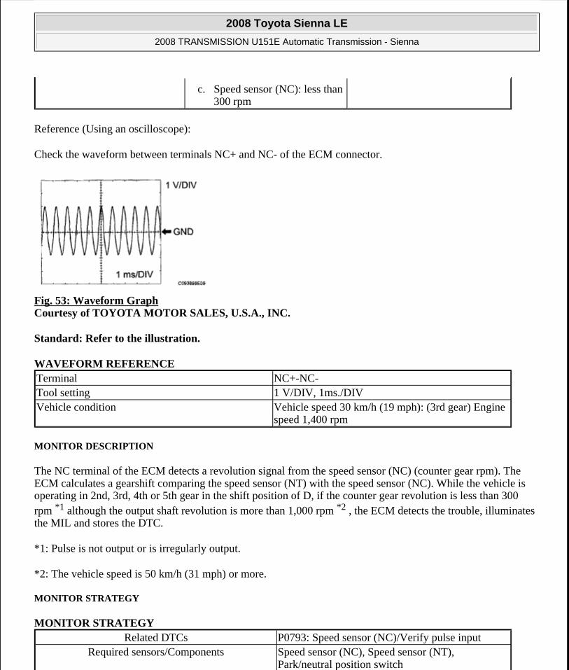
Reference (Using an oscilloscope):
Check the waveform between terminals NC+ and NC- of the ECM connector.
Fig. 53: Waveform Graph Courtesy of TOYOTA MOTOR SALES, U.S.A., INC.
Standard: Refer to the illustration.
WAVEFORM REFERENCE
MONITOR DESCRIPTION
The NC terminal of the ECM detects a revolution signal from the speed sensor (NC) (counter gear rpm). The ECM calculates a gearshift comparing the speed sensor (NT) with the speed sensor (NC). While the vehicle is operating in 2nd, 3rd, 4th or 5th gear in the shift position of D, if the counter gear revolution is less than 300 rpm *1 although the output shaft revolution is more than 1,000 rpm *2 , the ECM detects the trouble, illuminates the MIL and stores the DTC.
*1: Pulse is not output or is irregularly output.
*2: The vehicle speed is 50 km/h (31 mph) or more.
MONITOR STRATEGY
MONITOR STRATEGY
c. Speed sensor (NC): less than 300 rpm
Terminal NC+-NC-Tool setting 1 V/DIV, 1ms./DIVVehicle condition Vehicle speed 30 km/h (19 mph): (3rd gear) Engine
speed 1,400 rpm
Related DTCs P0793: Speed sensor (NC)/Verify pulse inputRequired sensors/Components Speed sensor (NC), Speed sensor (NT),
Park/neutral position switch
2008 Toyota Sienna LE
2008 TRANSMISSION U151E Automatic Transmission - Sienna
Microsoft
Wednesday, August 12, 2009 2:03:24 PM Page 123 © 2005 Mitchell Repair Information Company, LLC.

TYPICAL ENABLING CONDITIONS
TYPICAL ENABLING CONDITIONS
TYPICAL MALFUNCTION THRESHOLDS
TYPICAL MALFUNCTION THRESHOLDS
COMPONENT OPERATING RANGE
COMPONENT OPERATING RANGE
WIRING DIAGRAM
Frequency of operation ContinuousDuration 5 sec.
MIL operation ImmediateSequence of operation None
The monitor will run whenever this DTC is not present.
P0500 (VSS) P0748, P0778, P0798 (Shift solenoid valve(range))
Engine RunningNSW (STAR) switch OFFOutput shaft rpm 1,000 rpm or moreBattery voltage 8 V or moreIgnition switch ONStarter OFF
Sensor signal rpm Less than 300 rpm
Counter gear speed sensor (NC)
HINT: 3rd when shift lever position is D position (After warming up the engine);
Intermediate shaft speed (NC) becomes close to the engine speed.
2008 Toyota Sienna LE
2008 TRANSMISSION U151E Automatic Transmission - Sienna
Microsoft
Wednesday, August 12, 2009 2:03:24 PM Page 124 © 2005 Mitchell Repair Information Company, LLC.

Fig. 54: Counter Gear Speed Sensor - Wiring DiagramCourtesy of TOYOTA MOTOR SALES, U.S.A., INC.
INSPECTION PROCEDURE
HINT:
Using Techstream to read the Data List allows the values or states of switches, sensors, actuators and other items to be read without removing any parts. This non-intrusive inspection can be very useful because intermittent conditions or signals may be discovered before parts or wiring is disturbed. Reading the Data List information early in troubleshooting is one way to save diagnostic time.
1. READ DATA LIST
a. Warm up the engine.
b. Turn the ignition switch off.
c. Connect Techstream to the DLC3.
d. Turn the ignition switch to the ON position.
e. Turn on the tester.
f. Select the item "Powertrain / Engine and ECT / Data List".
g. According to the display on the tester, read the "Data List".
DATA LIST
HINT:
SPD (NC) is always 0 while driving:
Open or short in the sensor or circuit.
SPD (NC) is always more than 0 and less than 300 rpm while driving the vehicle at 50 km/h (31 mph) or more:
Sensor trouble, improper installation, or intermittent connection trouble of the circuit.
1. INSPECT SPEED SENSOR INSTALLATION
Tester Display Measurement Item/Range Normal Condition
SPD (NC)Counter Gear Speed/ display: 50
r/min
HINT: 3rd when shift lever position is D position (After warming up the engine);
Intermediate shaft speed (NC) becomes close to the engine speed.
2008 Toyota Sienna LE
2008 TRANSMISSION U151E Automatic Transmission - Sienna
Microsoft
Wednesday, August 12, 2009 2:03:24 PM Page 125 © 2005 Mitchell Repair Information Company, LLC.

a. Check the speed sensor installation.
OK: The installation bolt is tightened properly and there is no clearance between the sensor and transaxle case.
Fig. 55: Identifying Proper Installation Position Of Speed Sensor (NC) Courtesy of TOYOTA MOTOR SALES, U.S.A., INC.
NG: REPLACE SPEED SENSOR (NC)
OK: Go to Next Step
2. INSPECT SPEED SENSOR (NC)
a. Disconnect the speed sensor connector from the transaxle.
b. Measure the resistance according to the value(s) in the table below.
Standard resistance
RESISTANCE SPECIFICATION Tester Connection Specified Condition 20°C (68°F)
1 -2 560 to 680 ohms
2008 Toyota Sienna LE
2008 TRANSMISSION U151E Automatic Transmission - Sienna
Microsoft
Wednesday, August 12, 2009 2:03:24 PM Page 126 © 2005 Mitchell Repair Information Company, LLC.

Fig. 56: Identifying Speed Sensor Connector Terminals (NC)Courtesy of TOYOTA MOTOR SALES, U.S.A., INC.
NG: REPLACE SPEED SENSOR (NC)
OK: Go to Next Step
3. CHECK HARNESS AND CONNECTOR (SPEED SENSOR - ECM)
a. Connect the speed sensor connector.
b. Disconnect the ECM connector.
c. Measure the resistance according to the value(s) in the table below.
Standard resistance
RESISTANCE SPECIFICATION
d. Measure the resistance according to the value(s) in the table below.
Fig. 57: Identifying ECM Connector Courtesy of TOYOTA MOTOR SALES, U.S.A., INC.
Standard resistance (Check for short)
RESISTANCE SPECIFICATION
NG: REPAIR OR REPLACE HARNESS OR CONNECTOR
OK: REPLACE ECM
DTC P0796 PRESSURE CONTROL SOLENOID "C" PERFORMANCE (SHIFT SOLENOID VALVE
Tester Connection Specified Condition 20°C (68°F)E10-34 (NC+) - E10-26 (NC-) 560 to 680 ohms
Tester Connection Specified ConditionE10-34 (NC+) - Body ground
10 kohms or higherE10-26 (NC-) - Body ground
2008 Toyota Sienna LE
2008 TRANSMISSION U151E Automatic Transmission - Sienna
Microsoft
Wednesday, August 12, 2009 2:03:24 PM Page 127 © 2005 Mitchell Repair Information Company, LLC.

SL3)
SYSTEM DESCRIPTION
The ECM uses signals from the vehicle speed sensor to detect the actual gear position (1st, 2nd, 3rd, 4th or 5th gear).
Then the ECM compares the actual gear with the shift schedule in the ECM memory to detect mechanical troubles of the shift solenoid valves and valve body.
DTC DETECTION CONDITION AND TROUBLE AREA
MONITOR DESCRIPTION
The ECM commands gear shifts by turning the shift solenoid valves "ON/OFF". According to the input shaft revolution, intermediate (counter) shaft revolution and output shaft revolution, the ECM detects the actual gear position (1st, 2nd, 3rd, 4th or 5th gear position). When the gear position commanded by the ECM and the actual gear position are not the same, the ECM illuminates the MIL and stores the DTC.
MONITOR STRATEGY
MONITOR STRATEGY
DTC No. DTC Detection Condition Trouble Area
P0796
The gear required by the ECM does not match the actual gear when driving (2-trip detection logic)
Shift solenoid valve SL3 remains open or closed
Valve body is blocked
Automatic transaxle (clutch, brake or gear etc.)
Related DTCsP0796:
Shift solenoid valve SL3/OFF malfunction Shift solenoid valve SL3/ON malfunction
Required sensors/Components Shift solenoid valve SL3, Speed sensor (NT), Speed sensor (NC), Crankshaft position sensor
(NE)Frequency of operation Continuous
Duration
OFF malfunction (A) 0.8 sec.
OFF malfunction (B) 1 sec.
ON malfunction (A) and (B) 0.8 sec.
ON malfunction (C) 0.4 sec.
MIL operation 2 driving cyclesSequence of operation None
2008 Toyota Sienna LE
2008 TRANSMISSION U151E Automatic Transmission - Sienna
Microsoft
Wednesday, August 12, 2009 2:03:25 PM Page 128 © 2005 Mitchell Repair Information Company, LLC.

TYPICAL ENABLING CONDITIONS
All:
TYPICAL ENABLING CONDITIONS
OFF malfunction (A):
TYPICAL ENABLING CONDITIONS
OFF malfunction (B):
TYPICAL ENABLING CONDITIONS
ON malfunction (A):
TYPICAL ENABLING CONDITIONS
The monitor will run whenever this DTC is not present.
P0115-P0118 (ECT sensor) P0125 (Insufficient ECT for closed loop) P0500 (VSS)
P0748, P0778, P0798 (Shift solenoid valve (range))ECT (Engine coolant temperature) 10°C (50°F) or moreTransmission range "D"TFT (Transmission fluid temperature) -20°C (-4°F) or moreTFT sensor circuit Not circuit malfunctionECT sensor circuit Not circuit malfunctionTurbine speed sensor circuit Not circuit malfunctionIntermediate shaft speed sensor circuit Not circuit malfunctionOutput speed sensor circuit Not circuit malfunctionShift solenoid valve SL1 circuit Not circuit malfunctionShift solenoid valve SL2 circuit Not circuit malfunctionShift solenoid valve SL3 circuit Not circuit malfunctionShift solenoid valve S4 circuit Not circuit malfunctionShift solenoid valve SR circuit Not circuit malfunctionShift solenoid valve DSL circuit Not circuit malfunctionElectronic throttle system Not circuit malfunction
ECM selected gear 4th or 5thThrottle valve opening angle 4.5% or more at engine speed 1,900 rpm (Varies
with engine speed)
ECM selected gear 4thThrottle valve opening angle 5% or moreVehicle speed 10 km/h (6.2 mph) or more
ECM selected gear 1stVehicle speed Less than 40 km/h (24.9 mph)
2008 Toyota Sienna LE
2008 TRANSMISSION U151E Automatic Transmission - Sienna
Microsoft
Wednesday, August 12, 2009 2:03:25 PM Page 129 © 2005 Mitchell Repair Information Company, LLC.

ON malfunction (B):
TYPICAL ENABLING CONDITIONS
ON malfunction (C):
TYPICAL ENABLING CONDITIONS
TYPICAL MALFUNCTION THRESHOLDS
Either of the following conditions is met: OFF malfunction (A) and (B), or ON malfunctions (A), (B) and (C)
2 detections are necessary per driving cycle:
1st detection; temporary flag ON
2nd detection; pending fault code ON
OFF malfunction (A):
TYPICAL MALFUNCTION THRESHOLDS
OFF malfunction (B):
TYPICAL MALFUNCTION THRESHOLDS
ON malfunction (A):
TYPICAL MALFUNCTION THRESHOLDS
Throttle valve opening angle 4.5% or more at engine speed 1,900 rpm (Varies with engine speed)
ECM selected gear 3rdThrottle valve opening angle 5.0% or more at output speed 1,400 rpm (Varies
with engine speed)Malfunction of pressure control solenoid "B" (SL2) and "C" (SL3)
Not detected
Throttle valve opening angle 7.0% or more at output speed 1,050 rpm (Varies with engine speed)
Malfunction of pressure control solenoid "B" (SL2) Not detected
Input (turbine) speed/Intermediate shaft speed 0.93 to 1.07
Intermediate shaft speed/Output speed 1.02 to 1.16
Input (turbine) speed/Intermediate shaft speed 0.93 to 1.07
2008 Toyota Sienna LE
2008 TRANSMISSION U151E Automatic Transmission - Sienna
Microsoft
Wednesday, August 12, 2009 2:03:25 PM Page 130 © 2005 Mitchell Repair Information Company, LLC.

ON malfunction (B):
TYPICAL MALFUNCTION THRESHOLDS
ON malfunction (C):
TYPICAL MALFUNCTION THRESHOLDS
INSPECTION PROCEDURE
HINT:
Using Techstream to perform Active Test allows relays, VSVs, actuators and other items to be operated without removing any parts. This non-intrusive functional inspection can be very useful because intermittent operation may be discovered before parts or wiring is disturbed. Performing Active Test early in troubleshooting is one way to save diagnostic time. Data List information can be displayed while performing Active Test.
1. PERFORM ACTIVE TEST
a. Warm up the engine.
b. Turn the ignition switch off.
c. Connect Techstream to the DLC3.
d. Turn the ignition switch to the ON position.
e. Turn on the tester.
f. Select the item "Powertrain / Engine and ECT / Active Test".
g. According to the display on the tester, perform the "Active Test".
HINT:
While driving, the shift position can be forcibly changed with Techstream.
Comparing the shift position commanded by the Active Test with the actual shift position enables you to confirm the problem (See DATA LIST / ACTIVE TEST ).
ACTIVE TEST DETAIL
Input (turbine) speed - Intermediate shaft speed 700 rpm or more
Input (turbine) speed - Intermediate shaft speed Less than -500 rpm or 700 rpm or more
Tester Display Test Part Control Range Diagnostic Note[Test Details] Operate the shift solenoid valve and set the each shift position by yourself. [Vehicle Condition]
2008 Toyota Sienna LE
2008 TRANSMISSION U151E Automatic Transmission - Sienna
Microsoft
Wednesday, August 12, 2009 2:03:25 PM Page 131 © 2005 Mitchell Repair Information Company, LLC.

HINT:
This test can be conducted when the vehicle speed is 50 km/h (31 mph) or less.
The shift position commanded by the ECM is shown in the Data List/Shift Status display on Techstream.
1. CHECK OTHER DTCS OUTPUT (IN ADDITION TO DTC P0796)
a. Connect Techstream to the DLC3.
b. Turn the ignition switch to the ON position and turn the Techstream main switch ON.
c. When you use Techstream:
Select the item "DIAGNOSIS / ENHANCED OBD II / DTC INFO / CURRENT CODES".
d. Read the DTCs using Techstream.
Result
RESULT REFERENCE
HINT:
If any other codes besides "P0796" are output, perform the troubleshooting for those DTCs first.
B: Go to DTC CHART
A: Go to Next Step
2. INSPECT SHIFT SOLENOID VALVE SL3
Control the Shift Position
IDL: ON
Less than 50 km/h (31 mph)
[Others]
Press "-->" button: Shift up
Press "<--" button: Shift down
1st/2nd/3rd/4th/5thPossible to check the operation of the shift
solenoid valves.
Result Proceed toP0796 A
P0796 and other DTCs B
2008 Toyota Sienna LE
2008 TRANSMISSION U151E Automatic Transmission - Sienna
Microsoft
Wednesday, August 12, 2009 2:03:25 PM Page 132 © 2005 Mitchell Repair Information Company, LLC.
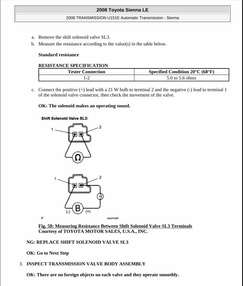
a. Remove the shift solenoid valve SL3.
b. Measure the resistance according to the value(s) in the table below.
Standard resistance
RESISTANCE SPECIFICATION
c. Connect the positive (+) lead with a 21 W bulb to terminal 2 and the negative (-) lead to terminal 1 of the solenoid valve connector, then check the movement of the valve.
OK: The solenoid makes an operating sound.
Fig. 58: Measuring Resistance Between Shift Solenoid Valve SL3 Terminals Courtesy of TOYOTA MOTOR SALES, U.S.A., INC.
NG: REPLACE SHIFT SOLENOID VALVE SL3
OK: Go to Next Step
3. INSPECT TRANSMISSION VALVE BODY ASSEMBLY
OK: There are no foreign objects on each valve and they operate smoothly.
Tester Connection Specified Condition 20°C (68°F)1-2 5.0 to 5.6 ohms
2008 Toyota Sienna LE
2008 TRANSMISSION U151E Automatic Transmission - Sienna
Microsoft
Wednesday, August 12, 2009 2:03:25 PM Page 133 © 2005 Mitchell Repair Information Company, LLC.

NG: REPAIR OR REPLACE TRANSMISSION VALVE BODY ASSEMBLY
OK: Go to Next Step
4. INSPECT TORQUE CONVERTER CLUTCH ASSEMBLY
OK: The torque converter clutch operates normally.
NG: REPLACE TORQUE CONVERTER CLUTCH ASSEMBLY
OK: REPAIR OR REPLACE AUTOMATIC TRANSAXLE ASSEMBLY
DTC P0798 PRESSURE CONTROL SOLENOID "C" ELECTRICAL (SHIFT SOLENOID VALVE SL3)
DESCRIPTION
Shifting from 1st to 5th is performed in combination with "ON" and "OFF" operation of the shift solenoid valves SL1, SL2, SL3, S4 and SR which are controlled by the ECM. If an open or short circuit occurs in either of the shift solenoid valves, the ECM controls the remaining normal shift solenoid valves to allow the vehicle to be operated smoothly (Fail safe function).
DTC DETECTION CONDITION AND TROUBLE AREA
MONITOR DESCRIPTION
The ECM commands gear shifts by turning the shift solenoid valves "ON/OFF". When there is an open or short circuit in any shift solenoid valve circuit, the ECM detects the problem and illuminates the MIL and stores the DTC. And the ECM performs the fail-safe function and turns the other normal shift solenoid valves "ON/OFF" (In case of an open or short circuit, the ECM stops sending current to the circuit.) (See DATA LIST / ACTIVE TEST ).
MONITOR STRATEGY
DTC No. DTC Detection Condition Trouble Area
P0798
The ECM checks for an open or short in the shift solenoid valve SL3 circuit while driving and shifting gears. (1-trip detection logic)
Output signal duty equals to 100 %.
(NOTE: SL3 output signal duty is less than 100 % under normal condition.)
Open or short in shift solenoid valve SL3 circuit
Shift solenoid valve SL3
ECM
2008 Toyota Sienna LE
2008 TRANSMISSION U151E Automatic Transmission - Sienna
Microsoft
Wednesday, August 12, 2009 2:03:25 PM Page 134 © 2005 Mitchell Repair Information Company, LLC.
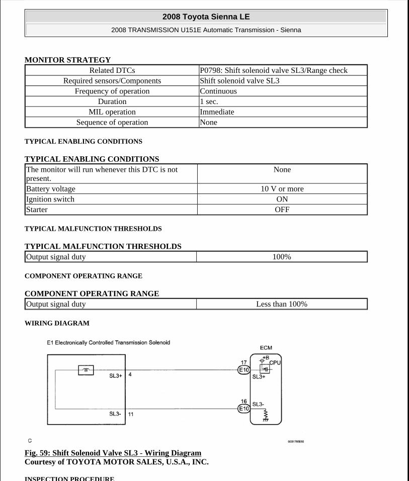
MONITOR STRATEGY
TYPICAL ENABLING CONDITIONS
TYPICAL ENABLING CONDITIONS
TYPICAL MALFUNCTION THRESHOLDS
TYPICAL MALFUNCTION THRESHOLDS
COMPONENT OPERATING RANGE
COMPONENT OPERATING RANGE
WIRING DIAGRAM
Fig. 59: Shift Solenoid Valve SL3 - Wiring Diagram Courtesy of TOYOTA MOTOR SALES, U.S.A., INC.
INSPECTION PROCEDURE
Related DTCs P0798: Shift solenoid valve SL3/Range checkRequired sensors/Components Shift solenoid valve SL3
Frequency of operation ContinuousDuration 1 sec.
MIL operation ImmediateSequence of operation None
The monitor will run whenever this DTC is not present.
None
Battery voltage 10 V or moreIgnition switch ONStarter OFF
Output signal duty 100%
Output signal duty Less than 100%
2008 Toyota Sienna LE
2008 TRANSMISSION U151E Automatic Transmission - Sienna
Microsoft
Wednesday, August 12, 2009 2:03:25 PM Page 135 © 2005 Mitchell Repair Information Company, LLC.

1. INSPECT TRANSMISSION WIRE (SL3)
a. Disconnect the transmission wire connector from the transaxle.
b. Measure the resistance according to the value(s) in the table below.
Standard resistance
RESISTANCE SPECIFICATION
c. Measure the resistance according to the value(s) in the table below.
Standard resistance (Check for short)
RESISTANCE SPECIFICATION
Fig. 60: Identifying Transmission Wire Connector Terminals Courtesy of TOYOTA MOTOR SALES, U.S.A., INC.
NG: Go to step 3
OK: Go to Next Step
2. CHECK HARNESS AND CONNECTOR (TRANSMISSION WIRE - ECM)
a. Connect the transmission wire connector to the transaxle.
b. Disconnect the connector from the ECM.
Tester Connection Specified Condition 20°C (68°F)4(SL3+)-11(SL3-) 5.0 to 5.6 ohms
Tester Connection Specified Condition4 (SL3+) - Body ground 10 kohms or higher11 (SL3-) - Body ground ?
2008 Toyota Sienna LE
2008 TRANSMISSION U151E Automatic Transmission - Sienna
Microsoft
Wednesday, August 12, 2009 2:03:25 PM Page 136 © 2005 Mitchell Repair Information Company, LLC.

c. Measure the resistance according to the value(s) in the table below.
Standard resistance
RESISTANCE SPECIFICATION
d. Measure the resistance according to the value(s) in the table below.
Standard resistance (Check for short)
RESISTANCE SPECIFICATION
Fig. 61: Identifying ECM Connector Courtesy of TOYOTA MOTOR SALES, U.S.A., INC.
NG: REPAIR OR REPLACE HARNESS OR CONNECTOR
OK: REPLACE ECM
3. INSPECT SHIFT SOLENOID VALVE SL3
a. Remove the shift solenoid valve SL3.
b. Measure the resistance according to the value(s) in the table below.
Standard resistance
RESISTANCE SPECIFICATION
Tester Connection Specified Condition 20°C (68°F)E10-17 (SL3+) - E10-16 (SL3-) 5.0 to 5.6 ohms
Tester Connection Specified ConditionE10-17 (SL3+) - Body ground
10 kohms or higherE10-16 (SL3-) - Body ground
Tester Connection Specified Condition 20°C (68°F)1-2 5.0 to 5.6 ohms
2008 Toyota Sienna LE
2008 TRANSMISSION U151E Automatic Transmission - Sienna
Microsoft
Wednesday, August 12, 2009 2:03:25 PM Page 137 © 2005 Mitchell Repair Information Company, LLC.

c. Connect the positive (+) lead with a 21 W bulb to terminal 2 and the negative (-) lead to terminal 1 of the solenoid valve connector, then check the movement of the valve.
OK: The solenoid makes an operating sound.
Fig. 62: Measuring Resistance Between Shift Solenoid Valve SL3 Terminals Courtesy of TOYOTA MOTOR SALES, U.S.A., INC.
NG: REPLACE SHIFT SOLENOID VALVE SL3
OK: REPAIR OR REPLACE TRANSMISSION WIRE
DTC P0982 SHIFT SOLENOID "D" CONTROL CIRCUIT LOW (SHIFT SOLENOID VALVE S4); DTC P0983 SHIFT SOLENOID "D" CONTROL CIRCUIT HIGH (SHIFT SOLENOID VALVE S4)
DESCRIPTION
Shifting from 1st to 5th is performed in combination with "ON" and "OFF" operation of the shift solenoid valves SL1, SL2, SL3, S4 and SR which are controlled by the ECM. If an open or short circuit occurs in either of the shift solenoid valves, the ECM controls the remaining normal shift solenoid valves to allow the vehicle to be operated smoothly (Fail safe function).
DTC DETECTION CONDITION AND TROUBLE AREA DTC No. DTC Detection Condition Trouble Area
ECM detects short in solenoid valve S4 circuit 2 times when
Short in shift solenoid valve S4 circuit
2008 Toyota Sienna LE
2008 TRANSMISSION U151E Automatic Transmission - Sienna
Microsoft
Wednesday, August 12, 2009 2:03:25 PM Page 138 © 2005 Mitchell Repair Information Company, LLC.

MONITOR DESCRIPTION
The ECM commands gear shifts by turning the shift solenoid valves "ON/OFF". When there is an open or short circuit in any shift solenoid valve circuit, the ECM detects the problem and illuminates the MIL and stores the DTC. And the ECM performs the fail-safe function and turns the other normal shift solenoid valves "ON/OFF" (In case of an open or short circuit, the ECM stops sending current to the circuit.) (See DATA LIST / ACTIVE TEST ).
MONITOR STRATEGY
MONITOR STRATEGY
TYPICAL ENABLING CONDITIONS
P0982: Range check (Low resistance):
TYPICAL ENABLING CONDITIONS
P0983: Range check (High resistance):
TYPICAL ENABLING CONDITIONS
P0982solenoid valve S4 is operated (1-trip detection logic)
Shift solenoid valve S4
ECM
P0983
ECM detects open in solenoid valve S4 circuit 2 times when solenoid valve S4 is not operated (1-trip detection logic)
Open in shift solenoid valve S4 circuit
Shift solenoid valve S4
ECM
Related DTCs
P0982: Shift solenoid valve S4/Range check (Low resistance) P0983: Shift solenoid valve S4/Range check (High resistance)
Required sensors/Components Shift solenoid valve S4Frequency of operation Continuous
Duration 0.064 sec.MIL operation Immediate
Sequence of operation None
The monitor will run whenever this DTC is not present.
None
Shift solenoid valve S4 ONBattery voltage 8 V or moreIgnition switch ONStarter OFF
2008 Toyota Sienna LE
2008 TRANSMISSION U151E Automatic Transmission - Sienna
Microsoft
Wednesday, August 12, 2009 2:03:25 PM Page 139 © 2005 Mitchell Repair Information Company, LLC.

TYPICAL MALFUNCTION THRESHOLDS
P0982: Range check (Low resistance):
TYPICAL MALFUNCTION THRESHOLDS
P0983: Range check (High resistance):
TYPICAL MALFUNCTION THRESHOLDS
COMPONENT OPERATING RANGE
COMPONENT OPERATING RANGE
WIRING DIAGRAM
Fig. 63: Shift Solenoid Valve S4 - Wiring Diagram Courtesy of TOYOTA MOTOR SALES, U.S.A., INC.
INSPECTION PROCEDURE
1. INSPECT TRANSMISSION WIRE (S4)
a. Disconnect the transmission wire connector from the transaxle.
The monitor will run whenever this DTC is not present.
None
Shift solenoid valve S4 OFFBattery voltage 8 V or moreIgnition switch ONStarter OFF
Shift solenoid valve S4 resistance 8 ohms or less
Shift solenoid valve S4 resistance 100 kohms or more
Shift solenoid valve S4 Resistance: 11 to 15 ohms at 20°C (68°F)
2008 Toyota Sienna LE
2008 TRANSMISSION U151E Automatic Transmission - Sienna
Microsoft
Wednesday, August 12, 2009 2:03:25 PM Page 140 © 2005 Mitchell Repair Information Company, LLC.

b. Measure the resistance according to the value(s) in the table below.
Standard resistance
RESISTANCE SPECIFICATION
Fig. 64: Identifying Transmission Wire Connector Terminals Courtesy of TOYOTA MOTOR SALES, U.S.A., INC.
NG: Go to step 3
OK: Go to Next Step
2. CHECK HARNESS AND CONNECTOR (TRANSMISSION WIRE - ECM)
a. Connect the transmission wire connector to the transaxle.
b. Disconnect the connector from the ECM.
c. Measure the resistance according to the value(s) in the table below.
Standard resistance
RESISTANCE SPECIFICATION
Tester Connection Specified Condition 20°C (68°F)3 (S4) - Body ground 11 to 15 ohms
Tester Connection Specified Condition 20°C (68°F)E10-10 (S4) - Body ground 11 to 15 ohms
2008 Toyota Sienna LE
2008 TRANSMISSION U151E Automatic Transmission - Sienna
Microsoft
Wednesday, August 12, 2009 2:03:25 PM Page 141 © 2005 Mitchell Repair Information Company, LLC.

Fig. 65: Identifying ECM Connector Courtesy of TOYOTA MOTOR SALES, U.S.A., INC.
NG: REPAIR OR REPLACE HARNESS OR CONNECTOR
OK: REPLACE ECM
3. INSPECT SHIFT SOLENOID VALVE S4
a. Remove the shift solenoid valve S4.
b. Measure the resistance according to the value(s) in the table below.
Standard resistance
RESISTANCE SPECIFICATION
c. Connect the positive (+) lead to the terminal of the solenoid connector, and the negative (-) lead to the solenoid body.
OK: The solenoid makes an operating sound.
Tester Connection Specified Condition 20°C (68°F)Solenoid Connector (S4) - Solenoid Body (S4) 11 to 15 ohms
2008 Toyota Sienna LE
2008 TRANSMISSION U151E Automatic Transmission - Sienna
Microsoft
Wednesday, August 12, 2009 2:03:25 PM Page 142 © 2005 Mitchell Repair Information Company, LLC.

Fig. 66: Measuring Resistance Between Shift Solenoid Valve S4 Terminals And Solenoid Body Courtesy of TOYOTA MOTOR SALES, U.S.A., INC.
NG: REPLACE SHIFT SOLENOID VALVE S4
OK: REPAIR OR REPLACE TRANSMISSION WIRE
DTC P0985 SHIFT SOLENOID "E" CONTROL CIRCUIT LOW (SHIFT SOLENOID VALVE SR); DTC P0986 SHIFT SOLENOID "E" CONTROL CIRCUIT HIGH (SHIFT SOLENOID VALVE SR)
DESCRIPTION
Shifting from 1st to 5th is performed in combination with "ON" and "OFF" operation of the shift solenoid valves SL1, SL2, SL3, S4 and SR which are controlled by the ECM. If an open or short circuit occurs in either of the shift solenoid valves, the ECM controls the remaining normal shift solenoid valves to allow the vehicle to be operated smoothly (Fail safe function).
DTC DETECTION CONDITION AND TROUBLE AREA
MONITOR DESCRIPTION
DTC No. DTC Detection Condition Trouble Area
P0985
ECM detects short in solenoid valve SR circuit 2 times when solenoid valve SR is operated (1-trip detection logic)
Short in shift solenoid valve SR circuit
Shift solenoid valve SR
ECM
P0986
ECM detects open in solenoid valve SR circuit 2 times when solenoid valve SR is not operated (1-trip detection logic)
Open in shift solenoid valve SR circuit
Shift solenoid valve SR
ECM
2008 Toyota Sienna LE
2008 TRANSMISSION U151E Automatic Transmission - Sienna
Microsoft
Wednesday, August 12, 2009 2:03:25 PM Page 143 © 2005 Mitchell Repair Information Company, LLC.

The ECM commands gear shifts by turning the shift solenoid valves "ON/OFF". When there is an open or short circuit in any shift solenoid valve circuit, the ECM detects the problem and illuminates the MIL and stores the DTC. And the ECM performs the fail-safe function and turns the other normal shift solenoid valves "ON/OFF" (In case of an open or short circuit, the ECM stops sending current to the circuit.) (See DATA LIST / ACTIVE TEST ).
MONITOR STRATEGY
MONITOR STRATEGY
TYPICAL ENABLING CONDITIONS
P0985: Range check (Low resistance):
TYPICAL ENABLING CONDITIONS
P0986: Range check (High resistance):
TYPICAL ENABLING CONDITIONS
TYPICAL MALFUNCTION THRESHOLDS
P0985: Range check (Low resistance):
Related DTCs
P0985: Shift solenoid valve SR/Range check (Low resistance) P0986: Shift solenoid valve SR/Range check (High resistance)
Required sensors/Components Shift solenoid valve SRFrequency of operation Continuous
Duration 0.064 sec.MIL operation Immediate
Sequence of operation None
The monitor will run whenever this DTC is not present.
None
Shift solenoid valve SR ONBattery voltage 8 V or moreIgnition switch ONStarter OFF
The monitor will run whenever this DTC is not present.
None
Shift solenoid valve SR OFFBattery voltage 8 V or moreIgnition switch ONStarter OFF
2008 Toyota Sienna LE
2008 TRANSMISSION U151E Automatic Transmission - Sienna
Microsoft
Wednesday, August 12, 2009 2:03:25 PM Page 144 © 2005 Mitchell Repair Information Company, LLC.

TYPICAL MALFUNCTION THRESHOLDS
P0986: Range check (High resistance):
TYPICAL MALFUNCTION THRESHOLDS
COMPONENT OPERATING RANGE
COMPONENT OPERATING RANGE
WIRING DIAGRAM
Fig. 67: Shift Solenoid Valve SR - Wiring Diagram Courtesy of TOYOTA MOTOR SALES, U.S.A., INC.
INSPECTION PROCEDURE
1. INSPECT TRANSMISSION WIRE (SR)
a. Disconnect the transmission wire connector from the transaxle.
b. Measure the resistance according to the value(s) in the table below.
Standard resistance
RESISTANCE SPECIFICATION
Shift solenoid valve SR resistance 8 ohms or less
Shift solenoid valve SR resistance 100 kohms or more
Shift solenoid valve SR Resistance: 11 to 15 ohms at 20°C (68°F)
Tester Connection Specified Condition 20°C (68°F)9 (SR) - Body ground 11 to 15 ohms
2008 Toyota Sienna LE
2008 TRANSMISSION U151E Automatic Transmission - Sienna
Microsoft
Wednesday, August 12, 2009 2:03:25 PM Page 145 © 2005 Mitchell Repair Information Company, LLC.

Fig. 68: Identifying Transmission Wire Connector Terminals (SR) Courtesy of TOYOTA MOTOR SALES, U.S.A., INC.
NG: Go to step 3
OK: Go to Next Step
2. CHECK HARNESS AND CONNECTOR (TRANSMISSION WIRE - ECM)
a. Connect the transmission wire connector to the transaxle.
b. Disconnect the connector from the ECM.
c. Measure the resistance according to the value(s) in the table below.
Standard resistance
RESISTANCE SPECIFICATION
Fig. 69: Identifying ECM Connector Courtesy of TOYOTA MOTOR SALES, U.S.A., INC.
Tester Connection Specified Condition 20°C (68°F)E10-9 (SR) - Body ground 11 to 15 ohms
2008 Toyota Sienna LE
2008 TRANSMISSION U151E Automatic Transmission - Sienna
Microsoft
Wednesday, August 12, 2009 2:03:25 PM Page 146 © 2005 Mitchell Repair Information Company, LLC.
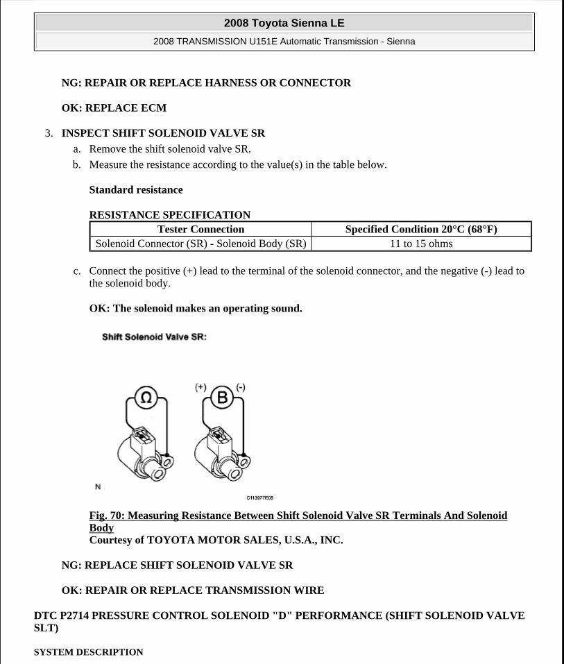
NG: REPAIR OR REPLACE HARNESS OR CONNECTOR
OK: REPLACE ECM
3. INSPECT SHIFT SOLENOID VALVE SR
a. Remove the shift solenoid valve SR.
b. Measure the resistance according to the value(s) in the table below.
Standard resistance
RESISTANCE SPECIFICATION
c. Connect the positive (+) lead to the terminal of the solenoid connector, and the negative (-) lead to the solenoid body.
OK: The solenoid makes an operating sound.
Fig. 70: Measuring Resistance Between Shift Solenoid Valve SR Terminals And Solenoid Body Courtesy of TOYOTA MOTOR SALES, U.S.A., INC.
NG: REPLACE SHIFT SOLENOID VALVE SR
OK: REPAIR OR REPLACE TRANSMISSION WIRE
DTC P2714 PRESSURE CONTROL SOLENOID "D" PERFORMANCE (SHIFT SOLENOID VALVE SLT)
SYSTEM DESCRIPTION
Tester Connection Specified Condition 20°C (68°F)Solenoid Connector (SR) - Solenoid Body (SR) 11 to 15 ohms
2008 Toyota Sienna LE
2008 TRANSMISSION U151E Automatic Transmission - Sienna
Microsoft
Wednesday, August 12, 2009 2:03:25 PM Page 147 © 2005 Mitchell Repair Information Company, LLC.

The linear solenoid valve (SLT) controls the transmission line pressure for smooth transmission operation based on signals from the throttle position sensor and the vehicle speed sensor. The ECM adjusts the duty ratio (*) of the SLT solenoid valve to control hydraulic line pressure coming from the primary regulator valve. Appropriate line pressure assures smooth shifting with varying engine outputs.
(*): Duty Ratio
The duty ratio is the ratio of the period of continuity in one cycle. For example, if A is the period of continuity in one cycle, and B is the period of non-continuity, then Duty Ratio=A/(A+B) x 100(%)
Fig. 71: Line Pressure Graph Courtesy of TOYOTA MOTOR SALES, U.S.A., INC.
DTC DETECTION CONDITION AND TROUBLE AREA DTC No. DTC Detection Condition Trouble Area
ECM detects a malfunction on
2008 Toyota Sienna LE
2008 TRANSMISSION U151E Automatic Transmission - Sienna
Microsoft
Wednesday, August 12, 2009 2:03:25 PM Page 148 © 2005 Mitchell Repair Information Company, LLC.

MONITOR DESCRIPTION
In any forward position, when the difference between the revolutions of the turbine, Intermediate and output shaft exceeds the specified value (varies with Intermediate, output speed) determined by the ECM, the ECM illuminates the MIL and store the DTC.
When shift solenoid valve SLT remains on, the oil pressure goes down and the clutch engagement force decreases.
MONITOR STRATEGY
MONITOR STRATEGY
TYPICAL ENABLING CONDITIONS
ON malfunction:
TYPICAL ENABLING CONDITIONS
P2714
SLT (ON side) according to the revolution difference of the turbine, intermediate and the output shaft, and also by the oil pressure. (2-trip detection logic)
Shift solenoid valve SLT remains closed
Valve body is blocked
Automatic transaxle (clutch, brake or gear, etc.)
NOTE: If you continue driving under these conditions, the clutch will burn out and the vehicle will no longer be drivable.
Related DTCs P2714: Shift solenoid valve SLT/ON malfunctionRequired sensors/Components Shift solenoid valve SLT, Speed sensor (NT),
Speed sensor (NC), Crankshaft position sensor (NE)
Frequency of operation ContinuousDuration 0.5 sec.MIL operation 2 driving cyclesSequence of operation None
The monitor will run whenever this DTC is not present.
None
Transmission range "D"TFT (Transmission fluid temperature) -20°C (-4°F) or moreTFT sensor circuit Not circuit malfunctionTurbine speed sensor circuit Not circuit malfunctionIntermediate shaft speed sensor circuit Not circuit malfunctionOutput speed sensor circuit Not circuit malfunction
2008 Toyota Sienna LE
2008 TRANSMISSION U151E Automatic Transmission - Sienna
Microsoft
Wednesday, August 12, 2009 2:03:25 PM Page 149 © 2005 Mitchell Repair Information Company, LLC.

ON malfunction (A):
TYPICAL ENABLING CONDITIONS
ON malfunction (B):
TYPICAL ENABLING CONDITIONS
Shift solenoid valve SL1 circuit Not circuit malfunctionShift solenoid valve SL2 circuit Not circuit malfunctionShift solenoid valve SL3 circuit Not circuit malfunctionShift solenoid valve S4 circuit Not circuit malfunctionShift solenoid valve SR circuit Not circuit malfunctionShift solenoid valve DSL circuit Not circuit malfunctionShift solenoid valve SLT circuit Not circuit malfunctionElectronic throttle system Not circuit malfunction
ECM selected gear 1stTemporary MAIN gear 1st or 2nd or 3rd or 4thNT - NC x Temporary MAIN gear ratio NT: Input (turbine) speed NC: Intermediate shaft speed
100 rpm or more at Intermediate shaft speed 1,000 rpm
Temporary U/D gear LowNC - NO x Temporary U/D gear ratio NO: Output speed
300 rpm or more at Output speed 1,000 rpm
TT TT: Turbine Torque
900 Nm or more
NT 250 rpm or moreNC 250 rpm or moreNO 250 rpm or more
ECM selected gear 2ndTemporary MAIN gear 1st or 2nd or 3rd or 4thNT - NC x Temporary MAIN gear ratio NT: Input (turbine) speed NC: Intermediate shaft speed
100 rpm or more at Intermediate shaft speed 1,000 rpm
Temporary U/D gear LowNC - NO x Temporary U/D gear ratio NO: Output speed
300 rpm or more at Output speed 1,000 rpm
TT TT: Turbine Torque 192 Nm or more
NT 250 rpm or moreNC 250 rpm or moreNO 250 rpm or more
2008 Toyota Sienna LE
2008 TRANSMISSION U151E Automatic Transmission - Sienna
Microsoft
Wednesday, August 12, 2009 2:03:25 PM Page 150 © 2005 Mitchell Repair Information Company, LLC.

ON malfunction (C):
TYPICAL ENABLING CONDITIONS
ON malfunction (D):
TYPICAL ENABLING CONDITIONS
ON malfunction (E):
TYPICAL ENABLING CONDITIONS
ECM selected gear 3rdTemporary MAIN gear 1st or 2nd or 3rd or 4thNT - NC x Temporary MAIN gear ratio NT: Input (turbine) speed NC: Intermediate shaft speed
100 rpm or more at Intermediate shaft speed 1,000 rpm
Temporary U/D gear LowNC - NO x Temporary U/D gear ratio NO: Output speed
300 rpm or more at Output speed 1,000 rpm
TT TT: Turbine Torque 900 Nm or more
NT 250 rpm or moreNC 250 rpm or moreNO 250 rpm or more
ECM selected gear 4thTemporary MAIN gear 1st or 2nd or 3rd or 4thNT - NC x Temporary MAIN gear ratio NT: Input (turbine) speed NC: Intermediate shaft speed
100 rpm or more at Intermediate shaft speed 1,000 rpm
Temporary U/D gear LowNC - NO x Temporary U/D gear ratio NO: Output speed
300 rpm or more at Output speed 1,000 rpm
TT TT: Turbine Torque
189 Nm or more
NT 250 rpm or moreNC 250 rpm or moreNO 250 rpm or more
ECM selected gear 5thTemporary MAIN gear 1st or 2nd or 3rd or 4thNT - NC x Temporary MAIN gear ratio NT: Input (turbine) speed NC: Intermediate shaft speed
100 rpm or more at Intermediate shaft speed 1,000 rpm
Temporary U/D gear Low
2008 Toyota Sienna LE
2008 TRANSMISSION U151E Automatic Transmission - Sienna
Microsoft
Wednesday, August 12, 2009 2:03:25 PM Page 151 © 2005 Mitchell Repair Information Company, LLC.

TYPICAL MALFUNCTION THRESHOLDS
[ON malfunction]
Detection condition: Total accumulated time of ON malfunctions (a), (b), (c), (d) and (e) is 0.5 second or more
ON malfunction (A):
TYPICAL MALFUNCTION THRESHOLDS
ON malfunction (B):
TYPICAL MALFUNCTION THRESHOLDS
ON malfunction (C):
TYPICAL MALFUNCTION THRESHOLDS
ON malfunction (D):
TYPICAL MALFUNCTION THRESHOLDS
NC - NO x Temporary U/D gear ratio NO: Output speed
300 rpm or more at Output speed 1,000 rpm
TT TT: Turbine Torque
189 Nm or more
NT 250 rpm or moreNC 250 rpm or moreNO 250 rpm or more
NT - NC x 1st gear ratio 100 rpm or more at Intermediate shaft speed 1,000 rpm
NC - NO x Low gear ratio 300 rpm or more at Output speed 1,000 rpmDuration 1 sec. or moreShift Solenoid valve SL1 Performance Not performance malfunction
NT - NC x 2nd gear ratio 100 rpm or more at Intermediate shaft speed 1,000 rpm
NC - NO x Low gear ratio 300 rpm or more at Output speed 1,000 rpmDuration 1 sec. or moreShift Solenoid valve SL1 Performance Not performance malfunction
NT - NC x 3rd gear ratio 100 rpm or more at Intermediate shaft speed 1,000 rpm
NC - NO x Low gear ratio 300 rpm or more at Output speed 1,000 rpmDuration 1 sec. or moreShift Solenoid valve SL1 Performance Not performance malfunction
2008 Toyota Sienna LE
2008 TRANSMISSION U151E Automatic Transmission - Sienna
Microsoft
Wednesday, August 12, 2009 2:03:25 PM Page 152 © 2005 Mitchell Repair Information Company, LLC.
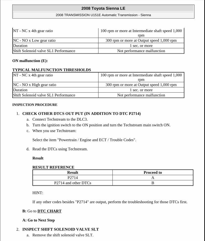
ON malfunction (E):
TYPICAL MALFUNCTION THRESHOLDS
INSPECTION PROCEDURE
1. CHECK OTHER DTCS OUT PUT (IN ADDITION TO DTC P2714)
a. Connect Techstream to the DLC3.
b. Turn the ignition switch to the ON position and turn the Techstream main switch ON.
c. When you use Techstream:
Select the item "Powertrain / Engine and ECT / Trouble Codes".
d. Read the DTCs using Techstream.
Result
RESULT REFERENCE
HINT:
If any other codes besides "P2714" are output, perform the troubleshooting for those DTCs first.
B: Go to DTC CHART
A: Go to Next Step
2. INSPECT SHIFT SOLENOID VALVE SLT
a. Remove the shift solenoid valve SLT.
NT - NC x 4th gear ratio 100 rpm or more at Intermediate shaft speed 1,000 rpm
NC - NO x Low gear ratio 300 rpm or more at Output speed 1,000 rpmDuration 1 sec. or moreShift Solenoid valve SL1 Performance Not performance malfunction
NT - NC x 4th gear ratio 100 rpm or more at Intermediate shaft speed 1,000 rpm
NC - NO x High gear ratio 300 rpm or more at Output speed 1,000 rpmDuration 1 sec. or moreShift Solenoid valve SL1 Performance Not performance malfunction
Result Proceed toP2714 A
P2714 and other DTCs B
2008 Toyota Sienna LE
2008 TRANSMISSION U151E Automatic Transmission - Sienna
Microsoft
Wednesday, August 12, 2009 2:03:25 PM Page 153 © 2005 Mitchell Repair Information Company, LLC.

b. Measure the resistance according to the value(s) in the table below.
Standard resistance
RESISTANCE SPECIFICATION
c. Connect the positive (+) lead with a 21 W bulb to terminal 2 and the negative (-) lead to terminal 1 of the solenoid valve connector, then check the movement of the valve.
OK: The solenoid makes an operating sound.
Fig. 72: Measuring Resistance Between Shift Solenoid Valve SLT Terminals Courtesy of TOYOTA MOTOR SALES, U.S.A., INC.
NG: REPLACE SHIFT SOLENOID VALVE SLT
OK: Go to Next Step
3. INSPECT TRANSMISSION VALVE BODY ASSEMBLY
OK: There are no foreign objects on each valve.
NG: REPAIR OR REPLACE TRANSMISSION VALVE BODY ASSEMBLY
Tester Connection Specified Condition 20°C (68°F)1-2 5.0 to 5.6 ohms
2008 Toyota Sienna LE
2008 TRANSMISSION U151E Automatic Transmission - Sienna
Microsoft
Wednesday, August 12, 2009 2:03:25 PM Page 154 © 2005 Mitchell Repair Information Company, LLC.

OK: Go to Next Step
4. INSPECT TORQUE CONVERTER CLUTCH ASSEMBLY
OK: The torque converter clutch operates normally.
NG: REPLACE TORQUE CONVERTER CLUTCH ASSEMBLY
OK: REPAIR OR REPLACE AUTOMATIC TRANSAXLE ASSEMBLY
DTC P2716 PRESSURE CONTROL SOLENOID "D" ELECTRICAL (SHIFT SOLENOID VALVE SLT)
DESCRIPTION
The linear solenoid valve (SLT) controls the transmission line pressure for smooth transmission operation based on signals from the throttle position sensor and the vehicle speed sensor. The ECM adjusts the duty cycle of the SLT solenoid valve to control hydraulic line pressure coming from the primary regulator valve. Appropriate line pressure assures smooth shifting with varying engine outputs.
(*): Duty Ratio
The duty ratio is the ratio of the period of continuity in one cycle.
For example, if A is the period of continuity in one cycle, and B is the period of non-continuity, then Duty Ratio = A/(A + B) x 100(%)
DTC DETECTION CONDITION AND TROUBLE AREA DTC No. DTC Detection Condition Trouble Area
P2716
Open or short is detected in shift solenoid valve SLT circuit for 1 second or more while driving (1-trip detecting logic).
Open or short in shift solenoid valve SLT circuit
Shift solenoid valve SLT
ECM
2008 Toyota Sienna LE
2008 TRANSMISSION U151E Automatic Transmission - Sienna
Microsoft
Wednesday, August 12, 2009 2:03:25 PM Page 155 © 2005 Mitchell Repair Information Company, LLC.
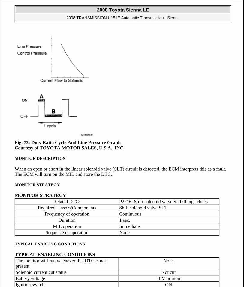
Fig. 73: Duty Ratio Cycle And Line Pressure Graph Courtesy of TOYOTA MOTOR SALES, U.S.A., INC.
MONITOR DESCRIPTION
When an open or short in the linear solenoid valve (SLT) circuit is detected, the ECM interprets this as a fault. The ECM will turn on the MIL and store the DTC.
MONITOR STRATEGY
MONITOR STRATEGY
TYPICAL ENABLING CONDITIONS
TYPICAL ENABLING CONDITIONS
Related DTCs P2716: Shift solenoid valve SLT/Range checkRequired sensors/Components Shift solenoid valve SLT
Frequency of operation ContinuousDuration 1 sec.
MIL operation ImmediateSequence of operation None
The monitor will run whenever this DTC is not present.
None
Solenoid current cut status Not cutBattery voltage 11 V or moreIgnition switch ON
2008 Toyota Sienna LE
2008 TRANSMISSION U151E Automatic Transmission - Sienna
Microsoft
Wednesday, August 12, 2009 2:03:25 PM Page 156 © 2005 Mitchell Repair Information Company, LLC.

TYPICAL MALFUNCTION THRESHOLDS
TYPICAL MALFUNCTION THRESHOLDS
COMPONENT OPERATING RANGE
COMPONENT OPERATING RANGE
WIRING DIAGRAM
Fig. 74: Shift Solenoid Valve SLT - Wiring Diagram Courtesy of TOYOTA MOTOR SALES, U.S.A., INC.
INSPECTION PROCEDURE
1. INSPECT TRANSMISSION WIRE (SLT)
a. Disconnect the transmission wire connector from the transaxle.
b. Measure the resistance according to the value(s) in the table below.
Standard resistance
RESISTANCE SPECIFICATION
c. Measure the resistance according to the value(s) in the table below.
Standard resistance (Check for short)
Starter OFFCPU commanded duty ratio to SLT 19% or more
Solenoid status from IC Fail (Open or short)
Shift solenoid valve SLT Resistance: 5.0 to 5.6 ohms at 20°C (68°F)
Tester Connection Specified Condition 20°C (68°F)2 (SLT+) - 8 (SLT-) 5.0 to 5.6 ohms
2008 Toyota Sienna LE
2008 TRANSMISSION U151E Automatic Transmission - Sienna
Microsoft
Wednesday, August 12, 2009 2:03:25 PM Page 157 © 2005 Mitchell Repair Information Company, LLC.

RESISTANCE SPECIFICATION
Fig. 75: Identifying Transmission Wire Connector Terminals (SLT) Courtesy of TOYOTA MOTOR SALES, U.S.A., INC.
NG: Go to step 3
OK: Go to Next Step
2. CHECK HARNESS AND CONNECTOR (TRANSMISSION WIRE - ECM)
a. Connect the transmission wire connector to the transaxle.
b. Disconnect the ECM connector.
c. Measure the resistance according to the value(s) in the table below.
Standard resistance
RESISTANCE SPECIFICATION
d. Measure the resistance according to the value(s) in the table below.
Standard resistance (Check for short)
RESISTANCE SPECIFICATION
Tester Connection Specified Condition2 (SLT+) - Body ground 10 kohms or higher8 (SLT-) - Body ground ?
Tester Connection Specified Condition 20°C (68°F)E10-13 (SLT+) - E10-12 (SLT-) 5.0 to 5.6 ohms
Tester Connection Specified ConditionE10-13 (SLT+) - Body ground
2008 Toyota Sienna LE
2008 TRANSMISSION U151E Automatic Transmission - Sienna
Microsoft
Wednesday, August 12, 2009 2:03:25 PM Page 158 © 2005 Mitchell Repair Information Company, LLC.

Fig. 76: Identifying ECM Connector Courtesy of TOYOTA MOTOR SALES, U.S.A., INC.
NG: REPAIR OR REPLACE HARNESS OR CONNECTOR
OK: REPLACE ECM
3. INSPECT SHIFT SOLENOID VALVE SLT
a. Remove the shift solenoid valve (SLT).
b. Measure the resistance according to the value(s) in the table below.
Standard resistance
RESISTANCE SPECIFICATION
c. Connect the positive (+) lead with a 21 W bulb to terminal 2 and the negative (-) lead to terminal 1 of the solenoid valve connector, then check the movement of the valve.
OK: The solenoid makes an operating sound.
E10-12 (SLT-) - Body ground 10 kohms or higher
Tester Connection Specified Condition 20°C (68°F)1 - 2 5.0 to 5.6 ohms
2008 Toyota Sienna LE
2008 TRANSMISSION U151E Automatic Transmission - Sienna
Microsoft
Wednesday, August 12, 2009 2:03:25 PM Page 159 © 2005 Mitchell Repair Information Company, LLC.

Fig. 77: Measuring Resistance Between Shift Solenoid Valve SLT Terminals Courtesy of TOYOTA MOTOR SALES, U.S.A., INC.
NG: REPLACE SHIFT SOLENOID VALVE SLT
OK: REPAIR OR REPLACE TRANSMISSION WIRE
DTC P2769 TORQUE CONVERTER CLUTCH SOLENOID CIRCUIT LOW (SHIFT SOLENOID VALVE DSL); DTC P2770 TORQUE CONVERTER CLUTCH SOLENOID CIRCUIT HIGH (SHIFT SOLENOID VALVE DSL)
DESCRIPTION
The shift solenoid valve DSL is turned "ON" and "OFF" by signals from the ECM in order to control the hydraulic pressure operation, the lock-up relay valve, which then controls operation of the lock-up clutch.
DTC DETECTION CONDITION AND TROUBLE AREA DTC No. DTC Detection Condition Trouble Area
P2769
ECM detects short in solenoid valve DSL circuit (0.1 sec.) when solenoid valve DSL is operated (2-trip detection logic)
Short in shift solenoid valve DSL circuit
Shift solenoid valve DSL
ECM
P2770
ECM detects open in solenoid valve DSL circuit (0.1 sec.) when solenoid valve DSL is not
Open in shift solenoid valve DSL circuit
Shift solenoid valve DSL
2008 Toyota Sienna LE
2008 TRANSMISSION U151E Automatic Transmission - Sienna
Microsoft
Wednesday, August 12, 2009 2:03:25 PM Page 160 © 2005 Mitchell Repair Information Company, LLC.

MONITOR DESCRIPTION
Torque converter lock-up is controlled by the ECM based on engine rpm, engine load, engine temperature, vehicle speed, transmission temperature, and shift range selection. The ECM determines the lock-up status of the torque converter by comparing the engine rpm (NE) to the input turbine rpm (NT). The ECM calculates the actual transmission gear by comparing input turbine rpm (NT) to counter gear rpm (NC). When conditions are appropriate, the ECM requests "lock-up" by applying control voltage to the shift solenoid DSL. When the DSL is opened, it applies pressure to the lock-up relay valve and locks the torque converter clutch. If the ECM detects an open or short in the DSL solenoid circuit, the ECM interprets this as a fault in the DSL solenoid or circuit. The ECM will turn on the MIL and store the DTC.
MONITOR STRATEGY
MONITOR STRATEGY
TYPICAL ENABLING CONDITIONS P2769
Range check (Low resistance):
TYPICAL ENABLING CONDITIONS
P2770: Range check (High resistance):
TYPICAL ENABLING CONDITIONS
operated (2-trip detection logic) ECM
Related DTCs
P2769: Shift solenoid valve DSL/Range check (Low resistance) P2770: Shift solenoid valve DSL/Range check (High resistance)
Required sensors/Components Shift solenoid valve DSLFrequency of operation Continuous
Duration 0.064 sec. or moreMIL operation 2 driving cycles
Sequence of operation None
The monitor will run whenever this DTC is not present.
None
Shift solenoid valve DSL ONSolenoid current cut status Not cutBattery voltage 8 V or moreIgnition switch ONStarter OFF
The monitor will run whenever this DTC is not present.
None
2008 Toyota Sienna LE
2008 TRANSMISSION U151E Automatic Transmission - Sienna
Microsoft
Wednesday, August 12, 2009 2:03:25 PM Page 161 © 2005 Mitchell Repair Information Company, LLC.

TYPICAL MALFUNCTION THRESHOLDS
P2769: Range check (Low resistance):
TYPICAL MALFUNCTION THRESHOLDS
P2770: Range check (High resistance):
TYPICAL MALFUNCTION THRESHOLDS
COMPONENT OPERATING RANGE
COMPONENT OPERATING RANGE
WIRING DIAGRAM
Fig. 78: Shift Solenoid Valve DSL - Wiring Diagram Courtesy of TOYOTA MOTOR SALES, U.S.A., INC.
INSPECTION PROCEDURE
1. INSPECT TRANSMISSION WIRE (DSL)
a. Disconnect the transmission wire connector from the transaxle.
b. Measure the resistance according to the value(s) in the table below.
Shift solenoid valve DSL ONBattery voltage 8 V or moreIgnition switch ONStarter OFF
Shift solenoid valve DSL resistance 8 ohms or less
Shift solenoid valve DSL resistance 100 kohms or more
Shift solenoid valve DSL Resistance: 11 to 13 ohms at 20°C (68°F)
2008 Toyota Sienna LE
2008 TRANSMISSION U151E Automatic Transmission - Sienna
Microsoft
Wednesday, August 12, 2009 2:03:25 PM Page 162 © 2005 Mitchell Repair Information Company, LLC.

Standard resistance
RESISTANCE SPECIFICATION
Fig. 79: Identifying Transmission Wire Connector Terminals (DSL) Courtesy of TOYOTA MOTOR SALES, U.S.A., INC.
NG: Go to step 3
OK: Go to Next Step
2. CHECK HARNESS AND CONNECTOR (TRANSMISSION WIRE - ECM)
a. Connect the transmission wire connector.
b. Disconnect the ECM connector.
c. Measure the resistance according to the value(s) in the table below.
Standard resistance
RESISTANCE SPECIFICATION
Tester Connection Specified Condition 20°C (68°F)10 (DSL) - Body ground 11 to 13 ohms
Tester Connection Specified Condition 20°C (68°F)E10-11 (DSL) - Body ground 11 to 13 ohms
2008 Toyota Sienna LE
2008 TRANSMISSION U151E Automatic Transmission - Sienna
Microsoft
Wednesday, August 12, 2009 2:03:25 PM Page 163 © 2005 Mitchell Repair Information Company, LLC.

Fig. 80: Identifying ECM Connector Courtesy of TOYOTA MOTOR SALES, U.S.A., INC.
NG: REPAIR OR REPLACE HARNESS OR CONNECTOR
OK: REPLACE ECM
3. INSPECT SHIFT SOLENOID VALVE DSL
a. Remove the shift solenoid valve DSL.
b. Measure the resistance according to the value(s) in the table below.
Standard resistance
RESISTANCE SPECIFICATION
c. Connect the positive (+) lead to the terminal of the solenoid connector, and the negative (-) lead to the solenoid body.
OK: The solenoid valve makes an operating sound.
Tester Connection Specified Condition 20°C (68°F)Solenoid Connector (DSL) - Solenoid Body
(DSL)11 to 13 ohms
2008 Toyota Sienna LE
2008 TRANSMISSION U151E Automatic Transmission - Sienna
Microsoft
Wednesday, August 12, 2009 2:03:25 PM Page 164 © 2005 Mitchell Repair Information Company, LLC.

Fig. 81: Measuring Resistance Between Shift Solenoid Valve DSL Terminals And Solenoid Body Courtesy of TOYOTA MOTOR SALES, U.S.A., INC.
NG: REPLACE SHIFT SOLENOID VALVE DSL
OK: REPAIR OR REPLACE TRANSMISSION WIRE
AUTOMATIC TRANSAXLE FLUID
ON-VEHICLE INSPECTION
1. CHECK FLUID LEVEL
HINT:
Drive the vehicle so that the engine and transaxle are at normal operating temperature.
Fluid temperature: 70 to 80°C (158 to 176°F)
a. Park the vehicle on a level surface and set the parking brake.
b. With the engine idling and the brake pedal depressed, move the shift lever to all positions from P to L and return to the P position.
c. Take out the dipstick and wipe it clean.
d. Put the dipstick back all the way.
e. Take out the dipstick again and check that the fluid level is within the HOT range.
If the fluid level is below the HOT range, add new fluid and recheck the fluid level.
If the fluid level exceeds the HOT range, drain the fluid once, add the proper amount of new fluid
2008 Toyota Sienna LE
2008 TRANSMISSION U151E Automatic Transmission - Sienna
Microsoft
Wednesday, August 12, 2009 2:03:25 PM Page 165 © 2005 Mitchell Repair Information Company, LLC.

and recheck the fluid level.
If there are leaks, it is necessary to repair or replace O-rings, FIPGs, oil seals, plugs and/or other parts.
Fig. 82: Identifying Fluid Level On Dipstick Courtesy of TOYOTA MOTOR SALES, U.S.A., INC.
PARK / NEUTRAL POSITION SWITCH
COMPONENTS
2008 Toyota Sienna LE
2008 TRANSMISSION U151E Automatic Transmission - Sienna
Microsoft
Wednesday, August 12, 2009 2:03:25 PM Page 166 © 2005 Mitchell Repair Information Company, LLC.

Fig. 83: Identifying Park/Neutral Position Switch Components With Torque Specifications Courtesy of TOYOTA MOTOR SALES, U.S.A., INC.
REMOVAL
1. REMOVE BATTERY
2. REMOVE AIR CLEANER ASSEMBLY
HINT:
(See REMOVAL )
3. SEPARATE TRANSMISSION CONTROL CABLE ASSEMBLY
a. Remove the nut from the control shaft lever.
b. Disconnect the control cable from the control shaft lever.
2008 Toyota Sienna LE
2008 TRANSMISSION U151E Automatic Transmission - Sienna
Microsoft
Wednesday, August 12, 2009 2:03:25 PM Page 167 © 2005 Mitchell Repair Information Company, LLC.

Fig. 84: Locating Control Shaft Lever Nut Courtesy of TOYOTA MOTOR SALES, U.S.A., INC.
c. Remove the clip and disconnect the control cable from the control cable bracket.
Fig. 85: Locating Control Cable Clip Courtesy of TOYOTA MOTOR SALES, U.S.A., INC.
4. REMOVE PARK/NEUTRAL POSITION SWITCH ASSEMBLY
a. Disconnect the park/neutral position switch connector.
Fig. 86: Locating Park/Neutral Position Switch Connector Courtesy of TOYOTA MOTOR SALES, U.S.A., INC.
b. Remove the nut, washer and control shaft lever.
NOTE: Do not hold the resin guide pipe.
2008 Toyota Sienna LE
2008 TRANSMISSION U151E Automatic Transmission - Sienna
Microsoft
Wednesday, August 12, 2009 2:03:25 PM Page 168 © 2005 Mitchell Repair Information Company, LLC.

Fig. 87: Locating Control Shaft Lever Nut Courtesy of TOYOTA MOTOR SALES, U.S.A., INC.
c. Using a screwdriver, pry up the lock plate.
Fig. 88: Locating Tabs For Lock Plate Courtesy of TOYOTA MOTOR SALES, U.S.A., INC.
d. Remove the lock nut and the lock plate.
Fig. 89: Locating Lock Plate Nut Courtesy of TOYOTA MOTOR SALES, U.S.A., INC.
e. Remove the 2 bolts and pull out the park/neutral position switch.
2008 Toyota Sienna LE
2008 TRANSMISSION U151E Automatic Transmission - Sienna
Microsoft
Wednesday, August 12, 2009 2:03:25 PM Page 169 © 2005 Mitchell Repair Information Company, LLC.

Fig. 90: Locating Park/Neutral Position Switch Bolts Courtesy of TOYOTA MOTOR SALES, U.S.A., INC.
INSPECTION
1. INSPECT PARK/NEUTRAL POSITION SWITCH ASSEMBLY OPERATION
a. Apply the parking brake and turn the ignition switch to the ON position.
b. Depress the brake pedal and check that the engine starts only when the shift lever is in the N or P position and the engine does not start when the shift lever is in other positions.
c. Check that the back up light comes on and the reverse warning buzzer sounds only when the shift lever is in the R position and the light and buzzer do not operate when the shift lever is in other positions.
d. If a failure is found, check the park/neutral position switch for continuity.
2. INSPECT PARK/NEUTRAL POSITION SWITCH ASSEMBLY
a. Jack up the vehicle.
b. Disconnect the park/neutral position switch connector.
c. Measure the resistance according to the value(s) in the table below when the shift lever is moved to each position.
Resistance
RESISTANCE SPECIFICATION Shift Position Tester Connection Specified Condition
P2 - 6 and 4 - 5
Below 1 ohmsExcept P 10 kohms or higher
R2-1
Below 1 ohmsExcept R 10 kohms or higher
N2 - 9 and 4 - 5
Below 1 ohmsExcept N 10 kohms or higherD and 4
2-7Below 1 ohms
Except D and 4 10 kohms or higher3
2-3Below 1 ohms
Except 3 10 kohms or higher
2008 Toyota Sienna LE
2008 TRANSMISSION U151E Automatic Transmission - Sienna
Microsoft
Wednesday, August 12, 2009 2:03:25 PM Page 170 © 2005 Mitchell Repair Information Company, LLC.

Fig. 91: Identifying Park/Neutral Position Switch Connector Terminals Courtesy of TOYOTA MOTOR SALES, U.S.A., INC.
ADJUSTMENT
1. ADJUST PARK/NEUTRAL POSITION SWITCH ASSEMBLY
a. Loosen the 2 bolts of the park/neutral position switch and move the shift lever to the N position.
b. Align the groove with the neutral basic line.
c. Hold the switch in position and tighten the 2 bolts.
Torque: 5.4 N*m (55 kgf*cm, 48 in.*lbf)
d. After adjustment, perform the inspection described in park/neutral position switch assembly operation.
Fig. 92: Identifying Park/Neutral Position Switch Groove And Neutral Basic Line Courtesy of TOYOTA MOTOR SALES, U.S.A., INC.
2 and L2-8
Below 1 ohmsExcept 2 and L 10 kohms or higher
2008 Toyota Sienna LE
2008 TRANSMISSION U151E Automatic Transmission - Sienna
Microsoft
Wednesday, August 12, 2009 2:03:25 PM Page 171 © 2005 Mitchell Repair Information Company, LLC.

INSTALLATION
1. INSTALL PARK/NEUTRAL POSITION SWITCH ASSEMBLY
a. Install the park/neutral position switch to the manual valve shaft.
b. Temporarily install the 2 bolts.
Fig. 93: Locating Park/Neutral Position Switch Bolts Courtesy of TOYOTA MOTOR SALES, U.S.A., INC.
c. Place a new lock plate and tighten the nut.
Torque: 6.9 N*m (70 kgf*cm, 61 in.*lbf)
d. Temporarily install the control shaft lever.
Fig. 94: Locating Lock Plate Nut Courtesy of TOYOTA MOTOR SALES, U.S.A., INC.
e. Turn the lever counterclockwise until it stops, then turn it clockwise 2 notches.
f. Remove the control shaft lever.
2008 Toyota Sienna LE
2008 TRANSMISSION U151E Automatic Transmission - Sienna
Microsoft
Wednesday, August 12, 2009 2:03:25 PM Page 172 © 2005 Mitchell Repair Information Company, LLC.

Fig. 95: Turning Lever Counterclockwise Courtesy of TOYOTA MOTOR SALES, U.S.A., INC.
g. Align the groove with the neutral basic line.
h. Hold the switch in position and tighten the 2 bolts.
Torque: 5.4 N*m (55 kgf*cm, 48 in.*lbf)
Fig. 96: Identifying Park/Neutral Position Switch Groove And Neutral Basic Line Courtesy of TOYOTA MOTOR SALES, U.S.A., INC.
i. Using a screwdriver, bend the tabs of the lock plate.
Fig. 97: Locating Tabs For Lock Plate Courtesy of TOYOTA MOTOR SALES, U.S.A., INC.
2008 Toyota Sienna LE
2008 TRANSMISSION U151E Automatic Transmission - Sienna
Microsoft
Wednesday, August 12, 2009 2:03:25 PM Page 173 © 2005 Mitchell Repair Information Company, LLC.

j. Install the control shaft lever, washer and the nut.
Torque: 13 N*m (130 kgf*cm, 9 ft.*lbf)
Fig. 98: Locating Control Shaft Lever Nut Courtesy of TOYOTA MOTOR SALES, U.S.A., INC.
k. Connect the park/neutral position switch connector.
Fig. 99: Locating Park/Neutral Position Switch Connector Courtesy of TOYOTA MOTOR SALES, U.S.A., INC.
2. CONNECT TRANSMISSION CONTROL CABLE ASSEMBLY
a. Connect the control cable to the control shaft lever with the nut.
Torque: 13 N*m (133 kgf*cm, 10 ft.*lbf)
2008 Toyota Sienna LE
2008 TRANSMISSION U151E Automatic Transmission - Sienna
Microsoft
Wednesday, August 12, 2009 2:03:25 PM Page 174 © 2005 Mitchell Repair Information Company, LLC.

Fig. 100: Locating Control Shaft Lever NutCourtesy of TOYOTA MOTOR SALES, U.S.A., INC.
b. Install the control cable with a new clip to the bracket.
Fig. 101: Locating Control Cable Clip Courtesy of TOYOTA MOTOR SALES, U.S.A., INC.
3. ADJUST PARK/NEUTRAL POSITION SWITCH ASSEMBLY (See ADJUSTMENT )
4. INSPECT PARK/NEUTRAL POSITION SWITCH ASSEMBLY OPERATION (See INSPECTION )
5. INSPECT SHIFT LEVER POSITION (See ADJUSTMENT )
6. ADJUST SHIFT LEVER POSITION (See ADJUSTMENT )
7. INSTALL AIR CLEANER ASSEMBLY
HINT:
(See INSTALLATION )
8. INSTALL BATTERY
TRANSMISSION WIRE
COMPONENTS
2008 Toyota Sienna LE
2008 TRANSMISSION U151E Automatic Transmission - Sienna
Microsoft
Wednesday, August 12, 2009 2:03:25 PM Page 175 © 2005 Mitchell Repair Information Company, LLC.

Fig. 102: Identifying Transmission Wire Components With Torque Specification Courtesy of TOYOTA MOTOR SALES, U.S.A., INC.
REMOVAL
1. DISCONNECT CABLE FROM NEGATIVE BATTERY TERMINAL
2. REMOVE ENGINE UNDER COVER NO.1
3. DRAIN AUTOMATIC TRANSAXLE FLUID
a. Remove the drain plug and gasket, and drain the ATF.
b. Install a new gasket and the drain plug.
2008 Toyota Sienna LE
2008 TRANSMISSION U151E Automatic Transmission - Sienna
Microsoft
Wednesday, August 12, 2009 2:03:26 PM Page 176 © 2005 Mitchell Repair Information Company, LLC.

Torque: 49 N*m (500 kgf*cm, 36 ft.*lbf)
4. REMOVE AUTOMATIC TRANSAXLE OIL PAN SUB-ASSEMBLY
a. Remove the 18 bolts, oil pan and gasket.
Fig. 103: Locating Oil Pan Bolts Courtesy of TOYOTA MOTOR SALES, U.S.A., INC.
b. Remove the 2 magnets from the oil pan.
Fig. 104: Identifying Magnets Courtesy of TOYOTA MOTOR SALES, U.S.A., INC.
c. Examine particles in the pan.
1. Collect any steel chips using the removed magnets. Look carefully at the chips and particles in the pan and on the magnets to see the type of wear which might be found in the transaxle.
Result:
Steel (magnetic):
Wear of the bearing, gear or plate
NOTE: Some fluid will remain in the oil pan. Carefully remove the oil pan so that fluid remaining in the pan does not spill out.
2008 Toyota Sienna LE
2008 TRANSMISSION U151E Automatic Transmission - Sienna
Microsoft
Wednesday, August 12, 2009 2:03:26 PM Page 177 © 2005 Mitchell Repair Information Company, LLC.

Brass (non-magnetic):
Wear of the bearing
Fig. 105: Collecting Steel Chips Using Magnet Courtesy of TOYOTA MOTOR SALES, U.S.A., INC.
5. DISCONNECT TRANSMISSION WIRE
a. Disconnect the 7 shift solenoid valve connectors.
b. Remove the bolt and lock plate, and disconnect the ATF temperature sensor.
Fig. 106: Locating Shift Solenoid Valve Connectors Courtesy of TOYOTA MOTOR SALES, U.S.A., INC.
6. REMOVE TRANSMISSION WIRE
a. Disconnect the transmission wire connector.
b. Remove the bolt and transmission wire.
c. Remove the O-ring from the transmission wire.
2008 Toyota Sienna LE
2008 TRANSMISSION U151E Automatic Transmission - Sienna
Microsoft
Wednesday, August 12, 2009 2:03:26 PM Page 178 © 2005 Mitchell Repair Information Company, LLC.

Fig. 107: Locating Transmission Wire Bolt Courtesy of TOYOTA MOTOR SALES, U.S.A., INC.
INSTALLATION
1. INSTALL TRANSMISSION WIRE
a. Coat the O-ring of the transmission wire connector with ATF and install it.
Fig. 108: Locating Transmission Wire Connector O-Ring Courtesy of TOYOTA MOTOR SALES, U.S.A., INC.
b. Install the transmission wire with the bolt.
Torque: 5.4 N*m (55 kgf*cm, 48 ft.*lbf)
Fig. 109: Locating Transmission Wire Bolt Courtesy of TOYOTA MOTOR SALES, U.S.A., INC.
2. CONNECT TRANSMISSION WIRE
2008 Toyota Sienna LE
2008 TRANSMISSION U151E Automatic Transmission - Sienna
Microsoft
Wednesday, August 12, 2009 2:03:26 PM Page 179 © 2005 Mitchell Repair Information Company, LLC.

a. Coat the O-ring of the ATF temperature sensor with ATF.
b. Install the ATF temperature sensor with the lock plate and bolt.
Torque: 6.6 N*m (67 kgf*cm, 58 ft.*lbf)
c. Connect the 7 shift solenoid valve connectors.
Fig. 110: Locating Shift Solenoid Valve Connectors Courtesy of TOYOTA MOTOR SALES, U.S.A., INC.
3. INSTALL AUTOMATIC TRANSAXLE OIL PAN SUB-ASSEMBLY
a. Install the 2 magnets in the oil pan.
b. Apply seal packing to the 18 bolts.
Seal packing:
THREE BOND 2430 or equivalent
Fig. 111: Identifying Magnets Courtesy of TOYOTA MOTOR SALES, U.S.A., INC.
c. Using a new gasket, install the oil pan to the transaxle case with the 18 bolts.
Torque: 7.8 N*m (80 kgf*cm, 69 in.*lbf)
NOTE: Apply seal packing to the bolts and tighten them within 10 minutes of
2008 Toyota Sienna LE
2008 TRANSMISSION U151E Automatic Transmission - Sienna
Microsoft
Wednesday, August 12, 2009 2:03:26 PM Page 180 © 2005 Mitchell Repair Information Company, LLC.

Fig. 112: Locating Oil Pan Bolts Courtesy of TOYOTA MOTOR SALES, U.S.A., INC.
4. CONNECT CABLE TO NEGATIVE BATTERY TERMINAL
5. ADD AUTOMATIC TRANSAXLE FLUID
6. INSPECT AUTOMATIC TRANSAXLE FLUID (See ON-VEHICLE INSPECTION )
7. INSTALL ENGINE UNDER COVER NO.1
8. RESET MEMORY
HINT:
(See INITIALIZATION )
VALVE BODY ASSEMBLY
COMPONENTS
application.
2008 Toyota Sienna LE
2008 TRANSMISSION U151E Automatic Transmission - Sienna
Microsoft
Wednesday, August 12, 2009 2:03:26 PM Page 181 © 2005 Mitchell Repair Information Company, LLC.

Fig. 113: Identifying Valve Body Assembly Components With Torque Specification (1 Of 2) Courtesy of TOYOTA MOTOR SALES, U.S.A., INC.
2008 Toyota Sienna LE
2008 TRANSMISSION U151E Automatic Transmission - Sienna
Microsoft
Wednesday, August 12, 2009 2:03:26 PM Page 182 © 2005 Mitchell Repair Information Company, LLC.

Fig. 114: Identifying Valve Body Assembly Components With Torque Specification (2 Of 2) Courtesy of TOYOTA MOTOR SALES, U.S.A., INC.
REMOVAL
1. REMOVE ENGINE UNDER COVER NO.1
2. DISCONNECT CABLE FROM NEGATIVE BATTERY TERMINAL
3. DRAIN AUTOMATIC TRANSAXLE FLUID (See REMOVAL )
2008 Toyota Sienna LE
2008 TRANSMISSION U151E Automatic Transmission - Sienna
Microsoft
Wednesday, August 12, 2009 2:03:26 PM Page 183 © 2005 Mitchell Repair Information Company, LLC.

4. REMOVE AUTOMATIC TRANSAXLE OIL PAN SUB-ASSEMBLY
a. Remove the 18 bolts, oil pan and gasket.
Fig. 115: Locating Oil Pan Bolts Courtesy of TOYOTA MOTOR SALES, U.S.A., INC.
b. Remove the 2 magnets from the oil pan.
Fig. 116: Identifying Magnets Courtesy of TOYOTA MOTOR SALES, U.S.A., INC.
c. Examine particles in the pan.
1. Collect any steel chips using the removed magnets. Look carefully at the chips and particles in the pan and on the magnets to see the type of wear which might be found in the transaxle.
Result:
Steel (magnetic):
Wear of the bearing, gear or plate
Brass (non-magnetic):
NOTE: Some fluid will remain in the oil pan. Carefully remove the oil pan so that the fluid remaining in the pan does not spill out.
2008 Toyota Sienna LE
2008 TRANSMISSION U151E Automatic Transmission - Sienna
Microsoft
Wednesday, August 12, 2009 2:03:26 PM Page 184 © 2005 Mitchell Repair Information Company, LLC.

Wear of the bearing
Fig. 117: Collecting Steel Chips Using Magnet Courtesy of TOYOTA MOTOR SALES, U.S.A., INC.
5. DISCONNECT TRANSMISSION WIRE
a. Disconnect the 7 shift solenoid valve connectors.
b. Remove the bolt and lock plate, and disconnect the ATF temperature sensor.
Fig. 118: Locating Shift Solenoid Valve Connectors Courtesy of TOYOTA MOTOR SALES, U.S.A., INC.
6. REMOVE VALVE BODY OIL STRAINER ASSEMBLY
a. Remove the 3 bolts and oil strainer.
NOTE: Be careful when removing the oil strainer as fluid will come out.
2008 Toyota Sienna LE
2008 TRANSMISSION U151E Automatic Transmission - Sienna
Microsoft
Wednesday, August 12, 2009 2:03:26 PM Page 185 © 2005 Mitchell Repair Information Company, LLC.

Fig. 119: Locating Oil Strainer Bolts Courtesy of TOYOTA MOTOR SALES, U.S.A., INC.
b. Remove the O-ring from the valve body oil strainer assembly.
Fig. 120: Locating Valve Body Oil Strainer O-Ring Courtesy of TOYOTA MOTOR SALES, U.S.A., INC.
7. REMOVE TRANSMISSION VALVE BODY ASSEMBLY
a. Support the valve body assembly and remove the 17 bolts and the transmission valve body assembly.
Fig. 121: Locating Valve Body Assembly Bolts Courtesy of TOYOTA MOTOR SALES, U.S.A., INC.
b. Remove the check ball body and the spring.
2008 Toyota Sienna LE
2008 TRANSMISSION U151E Automatic Transmission - Sienna
Microsoft
Wednesday, August 12, 2009 2:03:26 PM Page 186 © 2005 Mitchell Repair Information Company, LLC.

Fig. 122: Identifying Check Ball Body And Spring Courtesy of TOYOTA MOTOR SALES, U.S.A., INC.
c. Remove the bolt and lock plate from the valve body assembly.
d. Remove the shift solenoid valve SL3 and SLT from the valve body assembly.
Fig. 123: Identifying Shift Solenoid Valve SLT And SL3 Courtesy of TOYOTA MOTOR SALES, U.S.A., INC.
e. Remove the bolt and shift solenoid valve S4 from the valve body assembly.
Fig. 124: Locating Shift Solenoid Valve S4 Bolt Courtesy of TOYOTA MOTOR SALES, U.S.A., INC.
f. Remove the shift solenoid valve SR from the valve body assembly.
2008 Toyota Sienna LE
2008 TRANSMISSION U151E Automatic Transmission - Sienna
Microsoft
Wednesday, August 12, 2009 2:03:26 PM Page 187 © 2005 Mitchell Repair Information Company, LLC.
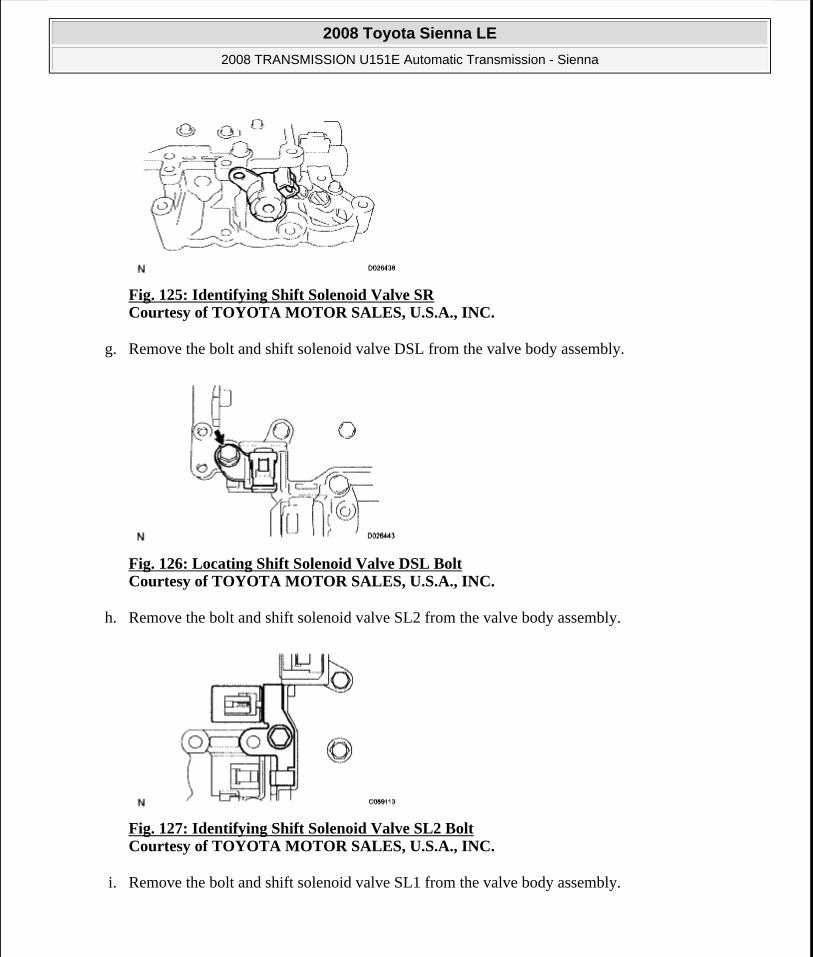
Fig. 125: Identifying Shift Solenoid Valve SR Courtesy of TOYOTA MOTOR SALES, U.S.A., INC.
g. Remove the bolt and shift solenoid valve DSL from the valve body assembly.
Fig. 126: Locating Shift Solenoid Valve DSL Bolt Courtesy of TOYOTA MOTOR SALES, U.S.A., INC.
h. Remove the bolt and shift solenoid valve SL2 from the valve body assembly.
Fig. 127: Identifying Shift Solenoid Valve SL2 Bolt Courtesy of TOYOTA MOTOR SALES, U.S.A., INC.
i. Remove the bolt and shift solenoid valve SL1 from the valve body assembly.
2008 Toyota Sienna LE
2008 TRANSMISSION U151E Automatic Transmission - Sienna
Microsoft
Wednesday, August 12, 2009 2:03:26 PM Page 188 © 2005 Mitchell Repair Information Company, LLC.

Fig. 128: Identifying Shift Solenoid Valve SL1 Bolt Courtesy of TOYOTA MOTOR SALES, U.S.A., INC.
INSTALLATION
1. INSTALL TRANSMISSION VALVE BODY ASSEMBLY
a. Install the shift solenoid valve SL1 to the valve body assembly with the bolt.
Torque: 6.6 N*m (67 kgf*cm, 58 in.*lbf)
Fig. 129: Identifying Shift Solenoid Valve SL1 Bolt Courtesy of TOYOTA MOTOR SALES, U.S.A., INC.
b. Install the shift solenoid valve SL2 to the valve body assembly with the bolt.
Torque: 11 N*m (110 kgf*cm, 8 ft.*lbf)
2008 Toyota Sienna LE
2008 TRANSMISSION U151E Automatic Transmission - Sienna
Microsoft
Wednesday, August 12, 2009 2:03:26 PM Page 189 © 2005 Mitchell Repair Information Company, LLC.
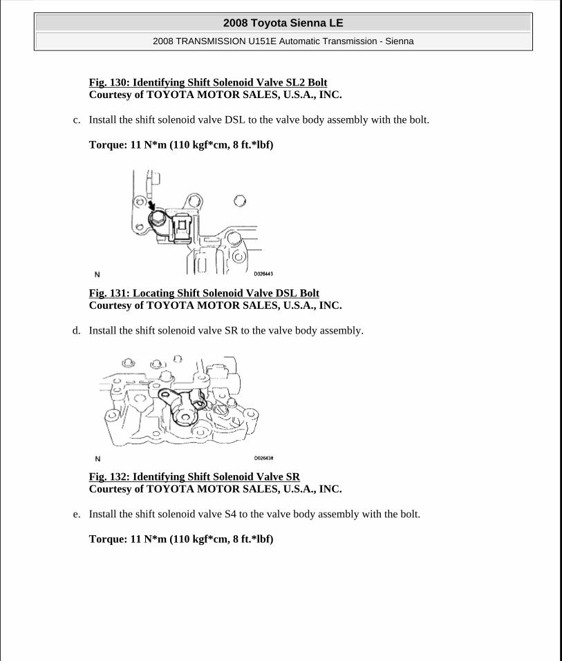
Fig. 130: Identifying Shift Solenoid Valve SL2 BoltCourtesy of TOYOTA MOTOR SALES, U.S.A., INC.
c. Install the shift solenoid valve DSL to the valve body assembly with the bolt.
Torque: 11 N*m (110 kgf*cm, 8 ft.*lbf)
Fig. 131: Locating Shift Solenoid Valve DSL Bolt Courtesy of TOYOTA MOTOR SALES, U.S.A., INC.
d. Install the shift solenoid valve SR to the valve body assembly.
Fig. 132: Identifying Shift Solenoid Valve SR Courtesy of TOYOTA MOTOR SALES, U.S.A., INC.
e. Install the shift solenoid valve S4 to the valve body assembly with the bolt.
Torque: 11 N*m (110 kgf*cm, 8 ft.*lbf)
2008 Toyota Sienna LE
2008 TRANSMISSION U151E Automatic Transmission - Sienna
Microsoft
Wednesday, August 12, 2009 2:03:26 PM Page 190 © 2005 Mitchell Repair Information Company, LLC.

Fig. 133: Locating Shift Solenoid Valve S4 Bolt Courtesy of TOYOTA MOTOR SALES, U.S.A., INC.
f. Install the shift solenoid valve SL3 and SLT to the valve body assembly.
g. Install the lock plate to the valve body assembly with the bolt.
Torque: 6.6 N*m (67 kgf*cm, 58 in.*lbf)
Fig. 134: Identifying Shift Solenoid Valve SLT And SL3 Courtesy of TOYOTA MOTOR SALES, U.S.A., INC.
h. Install the spring and check ball body.
Fig. 135: Identifying Check Ball Body And Spring Courtesy of TOYOTA MOTOR SALES, U.S.A., INC.
i. Align the groove of the manual valve with the pin of the lever.
2008 Toyota Sienna LE
2008 TRANSMISSION U151E Automatic Transmission - Sienna
Microsoft
Wednesday, August 12, 2009 2:03:26 PM Page 191 © 2005 Mitchell Repair Information Company, LLC.

j. Install the 17 bolts.
Torque: 11 N*m (110 kgf*cm, 8 ft.*lbf)
Bolt length:
Bolt A:
41 mm (1.614 in.)
Bolt B:
57 mm (2.244 in.)
Bolt C:
25 mm (0.984 in.)
Fig. 136: Locating Transmission Valve Body Assembly Bolts Courtesy of TOYOTA MOTOR SALES, U.S.A., INC.
2. INSTALL VALVE BODY OIL STRAINER ASSEMBLY
a. Coat a new O-ring with ATF.
b. Install the O-ring to the oil strainer.
NOTE: Push the valve body against the accumulator piston springs and check ball body to install the valve body.
First, temporarily tighten the bolts marked with (1) in the illustration because they are positioning bolts.
2008 Toyota Sienna LE
2008 TRANSMISSION U151E Automatic Transmission - Sienna
Microsoft
Wednesday, August 12, 2009 2:03:26 PM Page 192 © 2005 Mitchell Repair Information Company, LLC.

Fig. 137: Locating Valve Body Oil Strainer O-Ring Courtesy of TOYOTA MOTOR SALES, U.S.A., INC.
c. Install the oil strainer with the 3 bolts.
Torque: 11 N*m (110 kgf*cm, 8 ft.*lbf)
Fig. 138: Locating Oil Strainer Bolts Courtesy of TOYOTA MOTOR SALES, U.S.A., INC.
3. INSTALL TRANSMISSION WIRE
a. Coat the O-ring with ATF.
b. Install the ATF temperature sensor with the lock plate and bolt.
Torque: 6.6 N*m (67 kgf*cm, 58 in.*lbf)
c. Connect the 7 shift solenoid valve connectors.
2008 Toyota Sienna LE
2008 TRANSMISSION U151E Automatic Transmission - Sienna
Microsoft
Wednesday, August 12, 2009 2:03:26 PM Page 193 © 2005 Mitchell Repair Information Company, LLC.

Fig. 139: Locating Shift Solenoid Valve Connectors Courtesy of TOYOTA MOTOR SALES, U.S.A., INC.
4. INSTALL AUTOMATIC TRANSAXLE OIL PAN SUB-ASSEMBLY
a. Install the 2 magnets in the oil pan.
b. Apply seal packing or equivalent to the 18 bolts.
Seal packing:
THREE BOND 2430 or equivalent
Fig. 140: Identifying Magnets Courtesy of TOYOTA MOTOR SALES, U.S.A., INC.
c. Install the oil pan and new gasket with the 18 bolts to the transaxle case.
Torque: 7.8 N*m (80 kgf*cm, 69 in.*lbf)
5. CONNECT CABLE TO NEGATIVE BATTERY TERMINAL
6. ADD AUTOMATIC TRANSAXLE FLUID
7. CHECK FLUID LEVEL IN AUTOMATIC TRANSAXLE (See ON-VEHICLE INSPECTION )
8. INSTALL ENGINE UNDER COVER NO.1
9. RESET MEMORY
NOTE: Tighten the bolts within 10 minutes of sealant application.
2008 Toyota Sienna LE
2008 TRANSMISSION U151E Automatic Transmission - Sienna
Microsoft
Wednesday, August 12, 2009 2:03:26 PM Page 194 © 2005 Mitchell Repair Information Company, LLC.

HINT:
(See INITIALIZATION )
Fig. 141: Locating Oil Pan Bolts Courtesy of TOYOTA MOTOR SALES, U.S.A., INC.
SHIFT LOCK SYSTEM
ON-VEHICLE INSPECTION
1. CHECK SHIFT LOCK OPERATION
a. Move the shift lever to the P position.
b. Turn the ignition switch to the LOCK position.
c. Check that the shift lever cannot be moved to any position other than P.
d. Turn the ignition switch to the on position, depress the brake pedal and check that the shift lever can be moved to another position. If operation can not be done as specified, inspect the shift lock control unit.
2. CHECK SHIFT LOCK RELEASE BUTTON OPERATION
a. Using a small screwdriver, remove the shift lock release cover.
b. When operating the shift lever with the shift lock release button pressed, check that the lever can be moved to any position other than P.
If operation can not be done as specified, check the shift lever assembly installation condition.
3. CHECK KEY INTERLOCK OPERATION
a. Turn the ignition switch to the ON position.
b. Depress the brake pedal and move the shift lever to any position other than P.
c. Check that the ignition key cannot be turned to the LOCK position.
d. Move the shift lever to the P position, turn the ignition key to the LOCK position and check that the ignition key can be removed.
If operation cannot be done as specified, inspect the shift lock control unit.
2008 Toyota Sienna LE
2008 TRANSMISSION U151E Automatic Transmission - Sienna
Microsoft
Wednesday, August 12, 2009 2:03:26 PM Page 195 © 2005 Mitchell Repair Information Company, LLC.

4. INSPECT SHIFT LOCK CONTROL UNIT ASSEMBLY
a. Measure the voltage according to the value(s) in the table below.
HINT:
Do not disconnect the shift lock control unit assembly connector.
Fig. 142: Identifying Shift Lock Control Unit Connector Terminals Courtesy of TOYOTA MOTOR SALES, U.S.A., INC.
Voltage
VOLTAGE SPECIFICATION
b. Measure the resistance according to the value(s) in the table below.
HINT:
Do not disconnect the shift lock control unit assembly connector.
Terminal Measuring Condition Voltage (V)6 (ACC) - 8 (E) Ignition switch ACC 10 to 146 (ACC) - 8 (E) Ignition switch OFF Below 17 (STP) - 8 (E) Depress brake pedal 10 to 147 (STP) - 8 (E) Release brake pedal Below 1
12 (KLS+) - 8 (E)
1. Ignition switch ACC and shift lever P position
2. Ignition switch ACC and shift lever except P position
3. Ignition switch ACC and shift lever except P position (After approx. 1 second)
Below 1 7.5 to 11 6 to 9
1 (IG) - 8 (E) Ignition switch ON 10 to 141 (IG) - 8 (E) Ignition switch OFF Below 1
2008 Toyota Sienna LE
2008 TRANSMISSION U151E Automatic Transmission - Sienna
Microsoft
Wednesday, August 12, 2009 2:03:26 PM Page 196 © 2005 Mitchell Repair Information Company, LLC.

If operation cannot be done as specified, replace the shift lever assembly.
Fig. 143: Identifying Shift Lock Control Unit Connector Terminals Courtesy of TOYOTA MOTOR SALES, U.S.A., INC.
Resistance
RESISTANCE SPECIFICATION
5. INSPECT KEY INTER LOCK SOLENOID
a. Disconnect the solenoid connector.
b. Connect KLS+ (4) terminal to the batteries' positive (+) terminal and KLS (3) terminal to the battery negative (-) terminal, and apply about 12 V between KLS+ - KLS- terminals.
c. Check that operation noise can be heard from the solenoid.
If the solenoid does not operate, replace the solenoid.
Fig. 144: Identifying Key Inter Lock Solenoid Connector Terminals Courtesy of TOYOTA MOTOR SALES, U.S.A., INC.
6. INSPECT SHIFT LOCK SOLENOID
a. Disconnect the solenoid connector.
b. Connect SSL+ (2) terminal to the batteries' positive (+) terminal, and SLS- (1) terminal to the battery negative (-) terminal, and apply about 12 V between SLL+ - SLS- terminals.
c. Check that operation noise can be heard from the solenoid.
Terminal Measuring Condition Specified Value8 (E) - Body ground Always Below 1 ohms
2008 Toyota Sienna LE
2008 TRANSMISSION U151E Automatic Transmission - Sienna
Microsoft
Wednesday, August 12, 2009 2:03:26 PM Page 197 © 2005 Mitchell Repair Information Company, LLC.

If the solenoid does not operate, replace the solenoid.
Fig. 145: Identifying Shift Lock Solenoid Connector Terminals Courtesy of TOYOTA MOTOR SALES, U.S.A., INC.
SHIFT LEVER
COMPONENTS
2008 Toyota Sienna LE
2008 TRANSMISSION U151E Automatic Transmission - Sienna
Microsoft
Wednesday, August 12, 2009 2:03:26 PM Page 198 © 2005 Mitchell Repair Information Company, LLC.
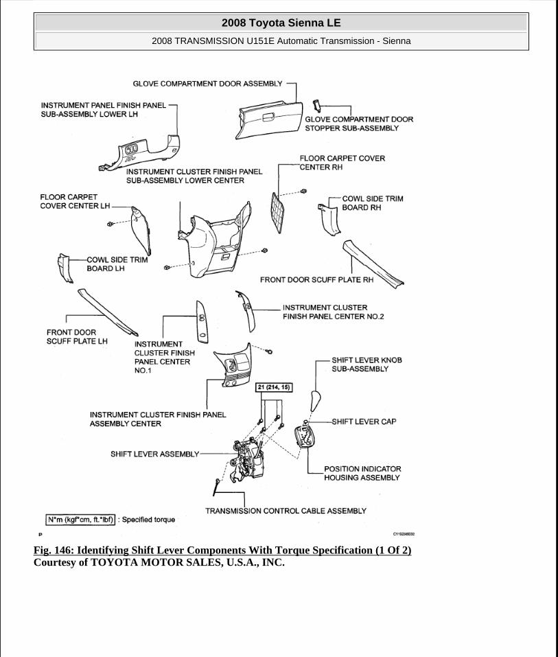
Fig. 146: Identifying Shift Lever Components With Torque Specification (1 Of 2) Courtesy of TOYOTA MOTOR SALES, U.S.A., INC.
2008 Toyota Sienna LE
2008 TRANSMISSION U151E Automatic Transmission - Sienna
Microsoft
Wednesday, August 12, 2009 2:03:26 PM Page 199 © 2005 Mitchell Repair Information Company, LLC.

Fig. 147: Identifying Shift Lever Components (2 Of 2) Courtesy of TOYOTA MOTOR SALES, U.S.A., INC.
REMOVAL
1. DISCONNECT BATTERY NEGATIVE TERMINAL
2. REMOVE FRONT DOOR SCUFF PLATE LH
HINT:
(See REMOVAL )
3. REMOVE FRONT DOOR SCUFF PLATE RH
2008 Toyota Sienna LE
2008 TRANSMISSION U151E Automatic Transmission - Sienna
Microsoft
Wednesday, August 12, 2009 2:03:26 PM Page 200 © 2005 Mitchell Repair Information Company, LLC.
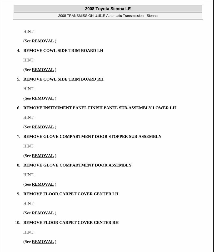
HINT:
(See REMOVAL )
4. REMOVE COWL SIDE TRIM BOARD LH
HINT:
(See REMOVAL )
5. REMOVE COWL SIDE TRIM BOARD RH
HINT:
(See REMOVAL )
6. REMOVE INSTRUMENT PANEL FINISH PANEL SUB-ASSEMBLY LOWER LH
HINT:
(See REMOVAL )
7. REMOVE GLOVE COMPARTMENT DOOR STOPPER SUB-ASSEMBLY
HINT:
(See REMOVAL )
8. REMOVE GLOVE COMPARTMENT DOOR ASSEMBLY
HINT:
(See REMOVAL )
9. REMOVE FLOOR CARPET COVER CENTER LH
HINT:
(See REMOVAL )
10. REMOVE FLOOR CARPET COVER CENTER RH
HINT:
(See REMOVAL )
2008 Toyota Sienna LE
2008 TRANSMISSION U151E Automatic Transmission - Sienna
Microsoft
Wednesday, August 12, 2009 2:03:26 PM Page 201 © 2005 Mitchell Repair Information Company, LLC.

11. REMOVE INSTRUMENT CLUSTER FINISH PANEL CENTER NO.1
HINT:
(See REMOVAL )
12. REMOVE INSTRUMENT CLUSTER FINISH PANEL CENTER NO.2
HINT:
(See REMOVAL )
13. REMOVE SHIFT LEVER KNOB SUB-ASSEMBLY
a. Remove the floor shift lever knob sub-assembly.
Fig. 148: Locating Floor Shift Lever Knob Sub-Assembly Courtesy of TOYOTA MOTOR SALES, U.S.A., INC.
14. REMOVE POSITION INDICATOR HOUSING ASSEMBLY
a. Using a screwdriver, remove the position indicator housing assembly from the instrument cluster finish panel assembly center.
Fig. 149: Identifying Position Indicator Housing Assembly Courtesy of TOYOTA MOTOR SALES, U.S.A., INC.
15. REMOVE INSTRUMENT CLUSTER FINISH PANEL ASSEMBLY CENTER
2008 Toyota Sienna LE
2008 TRANSMISSION U151E Automatic Transmission - Sienna
Microsoft
Wednesday, August 12, 2009 2:03:26 PM Page 202 © 2005 Mitchell Repair Information Company, LLC.

HINT:
(See REMOVAL )
16. REMOVE SHIFT LEVER CAP
a. Using a small screwdriver, remove the shift lever cap from the position indicator housing assembly.
Fig. 150: Identifying Shift Lever Cap Courtesy of TOYOTA MOTOR SALES, U.S.A., INC.
17. REMOVE INSTRUMENT CLUSTER FINISH PANEL SUB-ASSEMBLY LOWER CENTER
HINT:
(See REMOVAL )
18. DISCONNECT TRANSMISSION CONTROL CABLE ASSEMBLY
a. Using a screwdriver, disconnect the cable end from the shift lever assembly.
b. Using a small screwdriver, disconnect the outer of transmission control cable assembly from the shift lever assembly.
2008 Toyota Sienna LE
2008 TRANSMISSION U151E Automatic Transmission - Sienna
Microsoft
Wednesday, August 12, 2009 2:03:26 PM Page 203 © 2005 Mitchell Repair Information Company, LLC.
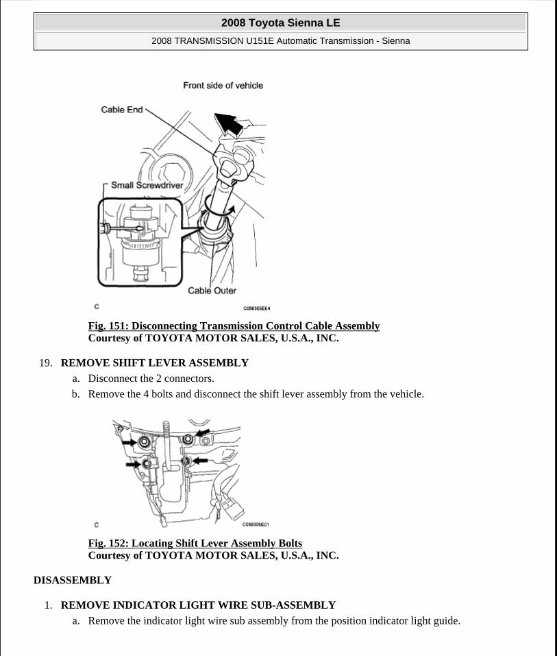
Fig. 151: Disconnecting Transmission Control Cable Assembly Courtesy of TOYOTA MOTOR SALES, U.S.A., INC.
19. REMOVE SHIFT LEVER ASSEMBLY
a. Disconnect the 2 connectors.
b. Remove the 4 bolts and disconnect the shift lever assembly from the vehicle.
Fig. 152: Locating Shift Lever Assembly Bolts Courtesy of TOYOTA MOTOR SALES, U.S.A., INC.
DISASSEMBLY
1. REMOVE INDICATOR LIGHT WIRE SUB-ASSEMBLY
a. Remove the indicator light wire sub assembly from the position indicator light guide.
2008 Toyota Sienna LE
2008 TRANSMISSION U151E Automatic Transmission - Sienna
Microsoft
Wednesday, August 12, 2009 2:03:26 PM Page 204 © 2005 Mitchell Repair Information Company, LLC.

Fig. 153: Identifying Indicator Light Wire Sub Assembly Courtesy of TOYOTA MOTOR SALES, U.S.A., INC.
2. REMOVE POSITION INDICATOR LIGHT BULB
a. Remove the shift position indicator light bulb from the indicator light wire sub-assembly
3. REMOVE POSITION INDICATOR SLIDE COVER
a. Remove the shift lever slide cover guide from the shift lever assembly.
Fig. 154: Identifying Shift Lever Slide Cover Guide And Position Indicator Slide Cover Courtesy of TOYOTA MOTOR SALES, U.S.A., INC.
b. Remove the position indicator slide cover from the shift lever assembly.
2008 Toyota Sienna LE
2008 TRANSMISSION U151E Automatic Transmission - Sienna
Microsoft
Wednesday, August 12, 2009 2:03:26 PM Page 205 © 2005 Mitchell Repair Information Company, LLC.
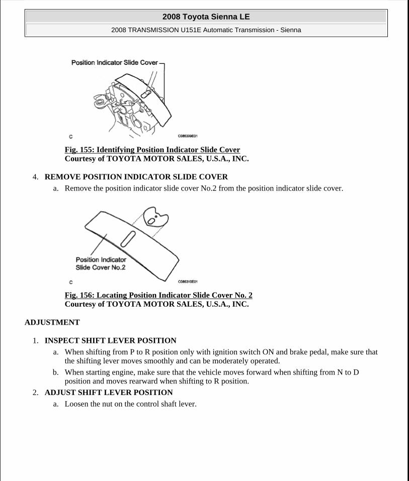
Fig. 155: Identifying Position Indicator Slide Cover Courtesy of TOYOTA MOTOR SALES, U.S.A., INC.
4. REMOVE POSITION INDICATOR SLIDE COVER
a. Remove the position indicator slide cover No.2 from the position indicator slide cover.
Fig. 156: Locating Position Indicator Slide Cover No. 2 Courtesy of TOYOTA MOTOR SALES, U.S.A., INC.
ADJUSTMENT
1. INSPECT SHIFT LEVER POSITION
a. When shifting from P to R position only with ignition switch ON and brake pedal, make sure that the shifting lever moves smoothly and can be moderately operated.
b. When starting engine, make sure that the vehicle moves forward when shifting from N to D position and moves rearward when shifting to R position.
2. ADJUST SHIFT LEVER POSITION
a. Loosen the nut on the control shaft lever.
2008 Toyota Sienna LE
2008 TRANSMISSION U151E Automatic Transmission - Sienna
Microsoft
Wednesday, August 12, 2009 2:03:26 PM Page 206 © 2005 Mitchell Repair Information Company, LLC.
Fig. 157: Locating Control Shaft Lever Nut Courtesy of TOYOTA MOTOR SALES, U.S.A., INC.
b. Push the control shaft fully downward.
c. Return the control shaft lever 2 notches to the N position.
Fig. 158: Returning Control Shaft Lever Notches To N Position Courtesy of TOYOTA MOTOR SALES, U.S.A., INC.
d. While pushing the control cable end up with the shift lever in the N position, install it to the control shaft lever with the nut.
Torque: 13 N*m (132.6 kgf*cm, 9.5 ft.*lbf)
e. Start the engine and make sure that the vehicle moves forward when shifting the lever from the N to D position and moves rearward when shifting it to the R position.
NOTE: If the control cable end is excessively pushed up, the shift lever can not be adjusted.
When tightening the nut, confirm that the control cable is properly stretched.
2008 Toyota Sienna LE
2008 TRANSMISSION U151E Automatic Transmission - Sienna
Microsoft
Wednesday, August 12, 2009 2:03:26 PM Page 207 © 2005 Mitchell Repair Information Company, LLC.

Fig. 159: Adjusting Transmission Control Cable Courtesy of TOYOTA MOTOR SALES, U.S.A., INC.
REASSEMBLY
1. INSTALL POSITION INDICATOR SLIDE COVER
a. Install the position indicator slide cover No.2 to the position indicator slide cover.
Fig. 160: Locating Position Indicator Slide Cover No. 2 Courtesy of TOYOTA MOTOR SALES, U.S.A., INC.
2. INSTALL POSITION INDICATOR SLIDE COVER
a. Install the position indicator slide cover to the shift lever assembly.
b. Install the shift lever slide cover guide to the shift lever assembly.
2008 Toyota Sienna LE
2008 TRANSMISSION U151E Automatic Transmission - Sienna
Microsoft
Wednesday, August 12, 2009 2:03:26 PM Page 208 © 2005 Mitchell Repair Information Company, LLC.

Fig. 161: Identifying Position Indicator Slide Cover And Shift Lever Slide Cover Guide Courtesy of TOYOTA MOTOR SALES, U.S.A., INC.
3. INSTALL POSITION INDICATOR LIGHT BULB
a. Install the shift position indicator light bulb to the indicator light wire sub-assembly.
4. INSTALL INDICATOR LIGHT WIRE SUB-ASSEMBLY
a. Install the indicator light wire sub-assembly to the shift lever assembly.
Fig. 162: Identifying Indicator Light Wire Sub-Assembly Courtesy of TOYOTA MOTOR SALES, U.S.A., INC.
INSTALLATION
1. INSTALL SHIFT LEVER ASSEMBLY
a. Install shift lever assembly to the vehicle with the 4 bolts.
2008 Toyota Sienna LE
2008 TRANSMISSION U151E Automatic Transmission - Sienna
Microsoft
Wednesday, August 12, 2009 2:03:26 PM Page 209 © 2005 Mitchell Repair Information Company, LLC.

Torque: 21 N*m (214 kgf*cm, 15 ft.*lbf)
b. Connect the 2 connectors to the shift lever assembly.
Fig. 163: Locating Shift Lever Assembly Bolts Courtesy of TOYOTA MOTOR SALES, U.S.A., INC.
2. INSTALL TRANSMISSION CONTROL CABLE ASSEMBLY
a. Install the cable outer to the shift lever plate
Fig. 164: Installing Cable Outer To Shift Lever Plate Courtesy of TOYOTA MOTOR SALES, U.S.A., INC.
b. When installing the transmission control cable assembly on the shift lever plate, place the projection to the shift lever plate (Fig. 165). Confirm that the spring in the shift cable outer has
NOTE: Into datum hole of shift lever into datum pin of instrument lower.
2008 Toyota Sienna LE
2008 TRANSMISSION U151E Automatic Transmission - Sienna
Microsoft
Wednesday, August 12, 2009 2:03:26 PM Page 210 © 2005 Mitchell Repair Information Company, LLC.
moved to the position (Fig. 165) shown in the illustration.
Confirm that the shift cable is installed on the shift lever plate properly.
Fig. 165: Identifying Shift Cable Outer Spring Position Courtesy of TOYOTA MOTOR SALES, U.S.A., INC.
3. INSTALL INSTRUMENT CLUSTER FINISH PANEL SUB-ASSEMBLY LOWER CENTER
HINT:
(See INSTALLATION )
4. INSTALL SHIFT LEVER CAP
a. Install the shift lever cap to the floor shift position indicator housing assembly.
Fig. 166: Identifying Shift Lever Cap Courtesy of TOYOTA MOTOR SALES, U.S.A., INC.
5. INSTALL POSITION INDICATOR HOUSING ASSEMBLY
a. install the position indicator housing assembly to the instrument cluster finish panel assembly center.
NOTE: To prevent torsion of the inner cable, the projection on the eye end should face rear.
Push the cable end to the bottom of the pin.
2008 Toyota Sienna LE
2008 TRANSMISSION U151E Automatic Transmission - Sienna
Microsoft
Wednesday, August 12, 2009 2:03:26 PM Page 211 © 2005 Mitchell Repair Information Company, LLC.

Fig. 167: Identifying Position Indicator Housing Assembly Courtesy of TOYOTA MOTOR SALES, U.S.A., INC.
6. INSTALL SHIFT LEVER KNOB SUB-ASSEMBLY
a. install the shift lever knob sub-assembly.
Fig. 168: Locating Shift Lever Knob Sub-Assembly Courtesy of TOYOTA MOTOR SALES, U.S.A., INC.
7. ADJUST SHIFT LEVER POSITION
HINT:
(See ADJUSTMENT )
8. INSPECT SHIFT LEVER POSITION
HINT:
(See ADJUSTMENT )
9. INSPECT KEY INTER LOCK OPERATION
HINT:
(See ON-VEHICLE INSPECTION )
2008 Toyota Sienna LE
2008 TRANSMISSION U151E Automatic Transmission - Sienna
Microsoft
Wednesday, August 12, 2009 2:03:26 PM Page 212 © 2005 Mitchell Repair Information Company, LLC.

10. INSPECT SHIFT LOCK OPERATION
HINT:
(See ON-VEHICLE INSPECTION )
11. INSPECT SHIFT LOCK RELEASE BUTTON OPERATION
HINT:
(See ON-VEHICLE INSPECTION )
TRANSMISSION CONTROL CABLE ASSEMBLY
COMPONENTS
Fig. 169: Identifying Transmission Control Cable Assembly Components With Torque Specification
2008 Toyota Sienna LE
2008 TRANSMISSION U151E Automatic Transmission - Sienna
Microsoft
Wednesday, August 12, 2009 2:03:26 PM Page 213 © 2005 Mitchell Repair Information Company, LLC.
Courtesy of TOYOTA MOTOR SALES, U.S.A., INC.
REMOVAL
1. DISCONNECT BATTERY NEGATIVE TERMINAL
2. REMOVE INSTRUMENT CLUSTER FINISH PANEL SUB-ASSEMBLY CENTER
HINT:
(See REMOVAL )
3. REMOVE TRANSMISSION CONTROL CABLE ASSEMBLY
a. Remove the nut from the control shaft lever.
b. Disconnect the transmission control cable assembly from the control shaft lever.
Fig. 170: Locating Control Shaft Lever Nut Courtesy of TOYOTA MOTOR SALES, U.S.A., INC.
c. Remove the clip and disconnect the transmission control cable assembly from the control cable bracket.
Fig. 171: Locating Transmission Control Cable Clip Courtesy of TOYOTA MOTOR SALES, U.S.A., INC.
d. Disconnect the transmission control cable assembly from the transmission control cable bracket No.2.
2008 Toyota Sienna LE
2008 TRANSMISSION U151E Automatic Transmission - Sienna
Microsoft
Wednesday, August 12, 2009 2:03:26 PM Page 214 © 2005 Mitchell Repair Information Company, LLC.

Fig. 172: Identifying Transmission Control Cable Bracket Courtesy of TOYOTA MOTOR SALES, U.S.A., INC.
e. Remove the 2 nuts and disconnect the transmission control cable assembly from the vehicle.
Fig. 173: Locating Transmission Control Cable Assembly Bolts Courtesy of TOYOTA MOTOR SALES, U.S.A., INC.
f. Using a screwdriver, disconnect the cable end from the shift lever assembly
g. Using a small screwdriver, disconnect the cable outer of transmission control cable assembly from the shift lever assembly.
h. Pull out the control cable from the vehicle.
2008 Toyota Sienna LE
2008 TRANSMISSION U151E Automatic Transmission - Sienna
Microsoft
Wednesday, August 12, 2009 2:03:26 PM Page 215 © 2005 Mitchell Repair Information Company, LLC.

Fig. 174: Disconnecting Cable End From Shift Lever Assembly Courtesy of TOYOTA MOTOR SALES, U.S.A., INC.
ADJUSTMENT
1. INSPECT SHIFT LEVER POSITION
a. When shifting from P to R position only with ignition switch ON and brake pedal, make sure that the shifting lever moves smoothly and can be moderately operated.
b. When starting engine, make sure that the vehicle moves forward when shifting from N to D position and moves rearward when shifting to R position.
2. ADJUST SHIFT LEVER POSITION
a. Loosen the nut on the control shaft lever.
Fig. 175: Locating Control Shaft Lever Nut Courtesy of TOYOTA MOTOR SALES, U.S.A., INC.
2008 Toyota Sienna LE
2008 TRANSMISSION U151E Automatic Transmission - Sienna
Microsoft
Wednesday, August 12, 2009 2:03:26 PM Page 216 © 2005 Mitchell Repair Information Company, LLC.
b. Push the control shaft fully downward.
c. Return the control shaft lever 2 notches to the N position.
Fig. 176: Returning Control Shaft Lever 2 Notches To N Position Courtesy of TOYOTA MOTOR SALES, U.S.A., INC.
d. While pushing the control cable end up with the shift lever in the N position, install it to the control shaft lever with the nut.
Torque: 13 N*m (132.6 kgf*cm, 9.5 ft.*lbf)
e. Start the engine and make sure that the vehicle moves forward when shifting the lever from the N to D position and moves rearward when shifting it to the R position.
NOTE: If the control cable end is excessively pushed up, the shift lever can not be adjusted.
When tightening the nut, confirm that the control cable is properly stretched.
2008 Toyota Sienna LE
2008 TRANSMISSION U151E Automatic Transmission - Sienna
Microsoft
Wednesday, August 12, 2009 2:03:27 PM Page 217 © 2005 Mitchell Repair Information Company, LLC.

Fig. 177: Adjusting Transmission Control Cable Courtesy of TOYOTA MOTOR SALES, U.S.A., INC.
INSTALLATION
1. INSTALL TRANSMISSION CONTROL CABLE ASSEMBLY
a. Pull in the control cable to the body.
b. Install the cable end, as shown in the illustration.
Fig. 178: Installing Cable End
2008 Toyota Sienna LE
2008 TRANSMISSION U151E Automatic Transmission - Sienna
Microsoft
Wednesday, August 12, 2009 2:03:27 PM Page 218 © 2005 Mitchell Repair Information Company, LLC.

Courtesy of TOYOTA MOTOR SALES, U.S.A., INC.
c. When installing the transmission control cable assembly on the shift lever plate, place the projection of the shift cable downward to fit in the groove of the shift lever plate (Fig. 179) Confirm that the spring in the shift cable outer has moved to the position (Fig. 179) shown in the illustration.
Confirm that the shift cable is installed on the shift lever plate properly.
Fig. 179: Identifying Spring In Shift Cable Outer Courtesy of TOYOTA MOTOR SALES, U.S.A., INC.
d. Install the transmission control cable assembly and 2 nuts.
Torque: 12 N*m (122 kgf*cm, 9 ft.*lbf)
Fig. 180: Locating Transmission Control Cable Assembly Bolts Courtesy of TOYOTA MOTOR SALES, U.S.A., INC.
e. Connect the transmission control cable assembly to the transmission control cable bracket No.2.
NOTE: To prevent torsion of the inner cable, the projection on the eye end should face rear.
Push the cable end to the bottom of the pin.
2008 Toyota Sienna LE
2008 TRANSMISSION U151E Automatic Transmission - Sienna
Microsoft
Wednesday, August 12, 2009 2:03:27 PM Page 219 © 2005 Mitchell Repair Information Company, LLC.
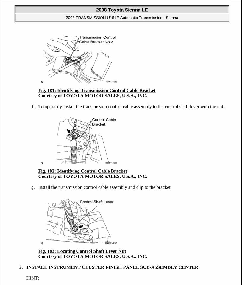
Fig. 181: Identifying Transmission Control Cable Bracket Courtesy of TOYOTA MOTOR SALES, U.S.A., INC.
f. Temporarily install the transmission control cable assembly to the control shaft lever with the nut.
Fig. 182: Identifying Control Cable Bracket Courtesy of TOYOTA MOTOR SALES, U.S.A., INC.
g. Install the transmission control cable assembly and clip to the bracket.
Fig. 183: Locating Control Shaft Lever Nut Courtesy of TOYOTA MOTOR SALES, U.S.A., INC.
2. INSTALL INSTRUMENT CLUSTER FINISH PANEL SUB-ASSEMBLY CENTER
HINT:
2008 Toyota Sienna LE
2008 TRANSMISSION U151E Automatic Transmission - Sienna
Microsoft
Wednesday, August 12, 2009 2:03:27 PM Page 220 © 2005 Mitchell Repair Information Company, LLC.
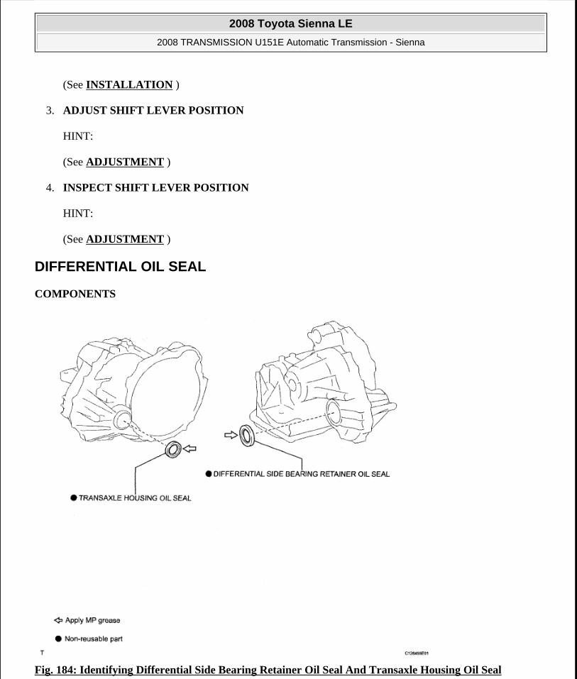
(See INSTALLATION )
3. ADJUST SHIFT LEVER POSITION
HINT:
(See ADJUSTMENT )
4. INSPECT SHIFT LEVER POSITION
HINT:
(See ADJUSTMENT )
DIFFERENTIAL OIL SEAL
COMPONENTS
Fig. 184: Identifying Differential Side Bearing Retainer Oil Seal And Transaxle Housing Oil Seal
2008 Toyota Sienna LE
2008 TRANSMISSION U151E Automatic Transmission - Sienna
Microsoft
Wednesday, August 12, 2009 2:03:27 PM Page 221 © 2005 Mitchell Repair Information Company, LLC.

Courtesy of TOYOTA MOTOR SALES, U.S.A., INC.
REMOVAL
1. REMOVE FRONT WHEELS
2. REMOVE ENGINE UNDER COVER NO.1
3. DRAIN AUTOMATIC TRANSAXLE FLUID
a. Remove the drain plug, gasket and drain ATF.
b. Install a new gasket and the drain plug.
Torque: 49 N*m (500 kgf*cm, 36 ft.*lbf)
4. REMOVE FRONT DRIVE SHAFT ASSEMBLY LH
HINT:
(See REMOVAL )
SST 09520-01010, 09520-24010 (09520-32040)
5. REMOVE FRONT DRIVE SHAFT ASSEMBLY RH (for 2WD)
HINT:
(See REMOVAL )
6. REMOVE TRANSAXLE HOUSING OIL SEAL
a. Using SST, pull out the oil seal.
SST 09308-00010
Fig. 185: Removing Transaxle Housing Oil Seal Courtesy of TOYOTA MOTOR SALES, U.S.A., INC.
7. REMOVE DIFFERENTIAL SIDE BEARING RETAINER OIL SEAL
a. Using SST, pull out the oil seal.
2008 Toyota Sienna LE
2008 TRANSMISSION U151E Automatic Transmission - Sienna
Microsoft
Wednesday, August 12, 2009 2:03:27 PM Page 222 © 2005 Mitchell Repair Information Company, LLC.

SST 09308-00010
Fig. 186: Removing Differential Side Bearing Retainer Oil Seal Courtesy of TOYOTA MOTOR SALES, U.S.A., INC.
INSTALLATION
1. INSTALL TRANSAXLE HOUSING OIL SEAL
a. Using SST and a hammer, install a new oil seal.
SST 09316-60011 (09316-00011)
Oil seal installation depth:
-0.5 to 0.5 mm (-0.020 to 0.020 in.)
b. Coat the lip of the oil seal with MP grease.
Fig. 187: Installing Transaxle Housing Oil Seal Courtesy of TOYOTA MOTOR SALES, U.S.A., INC.
2. INSTALL DIFFERENTIAL SIDE BEARING RETAINER OIL SEAL
a. Using SST and a hammer, install a new oil seal.
SST 09223-15020, 09950-70010 (09951 - 07150)
2008 Toyota Sienna LE
2008 TRANSMISSION U151E Automatic Transmission - Sienna
Microsoft
Wednesday, August 12, 2009 2:03:27 PM Page 223 © 2005 Mitchell Repair Information Company, LLC.

Oil seal installation depth:
-0.5 to 0.5 mm (-0.020 to 0.020 in.)
Fig. 188: Installing Differential Side Bearing Retainer Oil Seal Courtesy of TOYOTA MOTOR SALES, U.S.A., INC.
b. Coat the lip of the oil seal with MP grease.
3. INSTALL FRONT DRIVE SHAFT ASSEMBLY LH
HINT:
(See INSTALLATION )
4. INSTALL FRONT DRIVE SHAFT ASSEMBLY RH (for 2WD)
HINT:
(See INSTALLATION )
5. INSTALL FRONT WHEELS
Torque: 103 N*m (1,050 kgf*cm, 76 ft.*lbf)
6. ADD AUTOMATIC TRANSAXLE FLUID
7. INSPECT AUTOMATIC TRANSAXLE FLUID (See ON-VEHICLE INSPECTION )
8. INSTALL ENGINE UNDER COVER NO.1
9. CHECK ABS SPEED SENSOR SIGNAL
HINT:
(See DTC CHECK / CLEAR )
AUTOMATIC TRANSAXLE ASSEMBLY
COMPONENTS
2008 Toyota Sienna LE
2008 TRANSMISSION U151E Automatic Transmission - Sienna
Microsoft
Wednesday, August 12, 2009 2:03:27 PM Page 224 © 2005 Mitchell Repair Information Company, LLC.

Fig. 189: Identifying Automatic Transaxle Assembly Components With Torque Specification (1 Of 2) Courtesy of TOYOTA MOTOR SALES, U.S.A., INC.
2008 Toyota Sienna LE
2008 TRANSMISSION U151E Automatic Transmission - Sienna
Microsoft
Wednesday, August 12, 2009 2:03:27 PM Page 225 © 2005 Mitchell Repair Information Company, LLC.
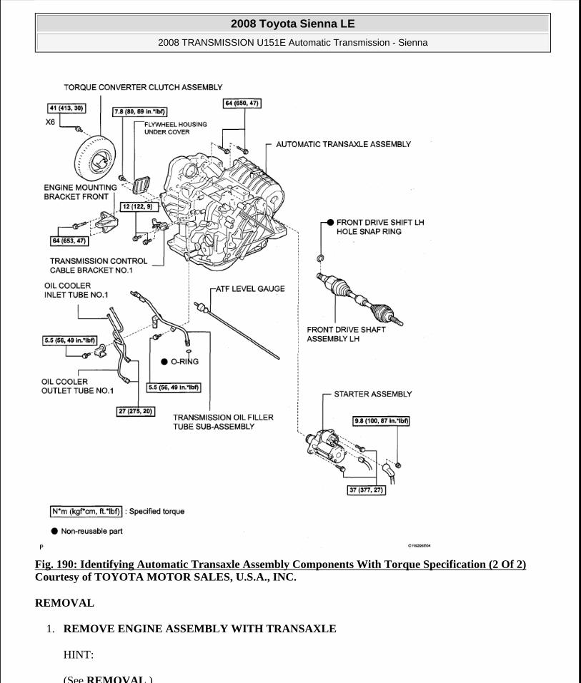
Fig. 190: Identifying Automatic Transaxle Assembly Components With Torque Specification (2 Of 2) Courtesy of TOYOTA MOTOR SALES, U.S.A., INC.
REMOVAL
1. REMOVE ENGINE ASSEMBLY WITH TRANSAXLE
HINT:
(See REMOVAL )
2008 Toyota Sienna LE
2008 TRANSMISSION U151E Automatic Transmission - Sienna
Microsoft
Wednesday, August 12, 2009 2:03:27 PM Page 226 © 2005 Mitchell Repair Information Company, LLC.

2. REMOVE FRONT DRIVE SHAFT ASSEMBLY LH
HINT:
(See REMOVAL )
3. REMOVE FRONT DRIVE SHAFT ASSEMBLY RH
HINT:
(See REMOVAL )
4. REMOVE TRANSMISSION CONTROL CABLE CLAMP
a. Remove the bolt and the transmission control cable clamp.
Fig. 191: Locating Transmission Control Cable Clamp Bolt Courtesy of TOYOTA MOTOR SALES, U.S.A., INC.
5. REMOVE WIRE HARNESS CLAMP
a. Disconnect the wire harnesses from the clamp.
b. Remove the 3 bolts and 2 clamps.
Fig. 192: Locating Wire Harness Clamps Bolts Courtesy of TOYOTA MOTOR SALES, U.S.A., INC.
6. DISCONNECT WIRE HARNESS
2008 Toyota Sienna LE
2008 TRANSMISSION U151E Automatic Transmission - Sienna
Microsoft
Wednesday, August 12, 2009 2:03:27 PM Page 227 © 2005 Mitchell Repair Information Company, LLC.

a. Remove the bolt and disconnect the wire harness.
Fig. 193: Locating Wire Harness Bolt Courtesy of TOYOTA MOTOR SALES, U.S.A., INC.
7. REMOVE STARTER ASSEMBLY
a. Disconnect the connector (1).
b. Remove the nut (2) and disconnect the starter wire.
c. Remove the 2 bolts (3) and starter assembly.
Fig. 194: Locating Starter Assembly Bolts Courtesy of TOYOTA MOTOR SALES, U.S.A., INC.
8. DISCONNECT CONNECTORS
a. Disconnect the transmission wire connector.
b. Disconnect the park/neutral position switch connector.
c. Disconnect the 2 speed sensor connectors.
2008 Toyota Sienna LE
2008 TRANSMISSION U151E Automatic Transmission - Sienna
Microsoft
Wednesday, August 12, 2009 2:03:27 PM Page 228 © 2005 Mitchell Repair Information Company, LLC.
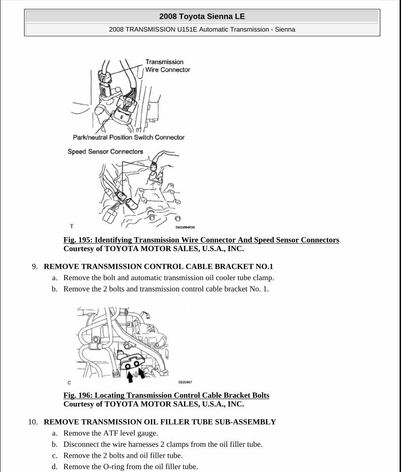
Fig. 195: Identifying Transmission Wire Connector And Speed Sensor Connectors Courtesy of TOYOTA MOTOR SALES, U.S.A., INC.
9. REMOVE TRANSMISSION CONTROL CABLE BRACKET NO.1
a. Remove the bolt and automatic transmission oil cooler tube clamp.
b. Remove the 2 bolts and transmission control cable bracket No. 1.
Fig. 196: Locating Transmission Control Cable Bracket Bolts Courtesy of TOYOTA MOTOR SALES, U.S.A., INC.
10. REMOVE TRANSMISSION OIL FILLER TUBE SUB-ASSEMBLY
a. Remove the ATF level gauge.
b. Disconnect the wire harnesses 2 clamps from the oil filler tube.
c. Remove the 2 bolts and oil filler tube.
d. Remove the O-ring from the oil filler tube.
2008 Toyota Sienna LE
2008 TRANSMISSION U151E Automatic Transmission - Sienna
Microsoft
Wednesday, August 12, 2009 2:03:27 PM Page 229 © 2005 Mitchell Repair Information Company, LLC.

Fig. 197: Locating Transmission Oil Filler Tube Bolts Courtesy of TOYOTA MOTOR SALES, U.S.A., INC.
11. REMOVE OIL COOLER INLET TUBE NO.1
a. Using SST and a wrench, disconnect the oil cooler inlet tube No.1.
SST 09023-12701
Fig. 198: Disconnecting Oil Cooler Inlet Tube Courtesy of TOYOTA MOTOR SALES, U.S.A., INC.
12. REMOVE OIL COOLER OUTLET TUBE NO.1
a. Using SST and a wrench, disconnect the oil cooler outlet tube No.1.
SST 09023-12701
13. REMOVE ENGINE MOUNTING BRACKET FRONT
a. Remove the 3 bolts and engine mounting bracket front.
2008 Toyota Sienna LE
2008 TRANSMISSION U151E Automatic Transmission - Sienna
Microsoft
Wednesday, August 12, 2009 2:03:27 PM Page 230 © 2005 Mitchell Repair Information Company, LLC.

Fig. 199: Locating Engine Mounting Bracket Bolts (Front) Courtesy of TOYOTA MOTOR SALES, U.S.A., INC.
14. REMOVE AUTOMATIC TRANSAXLE ASSEMBLY
a. Remove the 2 bolts and flywheel housing under cover.
Fig. 200: Locating Flywheel Housing Under Cover Bolts Courtesy of TOYOTA MOTOR SALES, U.S.A., INC.
b. Turn the crankshaft to gain access and remove the 6 bolts while holding the crankshaft pulley bolt with a wrench.
HINT:
There will be one green colored bolt.
Fig. 201: Locating Torque Converter Clutch Mounting Bolts
2008 Toyota Sienna LE
2008 TRANSMISSION U151E Automatic Transmission - Sienna
Microsoft
Wednesday, August 12, 2009 2:03:27 PM Page 231 © 2005 Mitchell Repair Information Company, LLC.

Courtesy of TOYOTA MOTOR SALES, U.S.A., INC.
c. Remove the 10 bolts.
d. Separate and remove the automatic transaxle.
Fig. 202: Locating Automatic Transaxle Assembly Bolts Courtesy of TOYOTA MOTOR SALES, U.S.A., INC.
15. REMOVE TORQUE CONVERTER CLUTCH ASSEMBLY
16. INSPECT TORQUE CONVERTER CLUTCH ASSEMBLY
HINT:
(See INSPECTION )
INSTALLATION
1. INSTALL TORQUE CONVERTER CLUTCH ASSEMBLY
a. Install the torque converter clutch to the automatic transaxle.
b. Using vernier calipers and a straight edge, measure the dimension "A" between the transaxle fitting part of the engine and the converter fitting part of the drive plate (*1).
Fig. 203: Measuring Dimension A Between Transaxle Fitting Part Of Engine And Converter Fitting Part Of Drive Plate Courtesy of TOYOTA MOTOR SALES, U.S.A., INC.
2008 Toyota Sienna LE
2008 TRANSMISSION U151E Automatic Transmission - Sienna
Microsoft
Wednesday, August 12, 2009 2:03:27 PM Page 232 © 2005 Mitchell Repair Information Company, LLC.

c. Using vernier calipers and a straight edge, measure the dimension "B" shown in the illustration and check that "B" is greater than "A" (measured in step (*1)).
Standard:
A + 1 mm (0.03937 in.) or more
Fig. 204: Measuring Dimension B Courtesy of TOYOTA MOTOR SALES, U.S.A., INC.
2. INSTALL AUTOMATIC TRANSAXLE ASSEMBLY
a. Install the automatic transaxle to the engine with the 10 bolts.
Torque: Bolt A
64 N*m (650 kgf*cm, 47 ft.*lbf)
Bolt B
46 N*m (470 kgf*cm, 34 ft.*lbf)
Bolt C
43 N*m (439 kgf*cm, 32 ft.*lbf)
NOTE: Remember to minus the thickness of the straight edge.
2008 Toyota Sienna LE
2008 TRANSMISSION U151E Automatic Transmission - Sienna
Microsoft
Wednesday, August 12, 2009 2:03:27 PM Page 233 © 2005 Mitchell Repair Information Company, LLC.
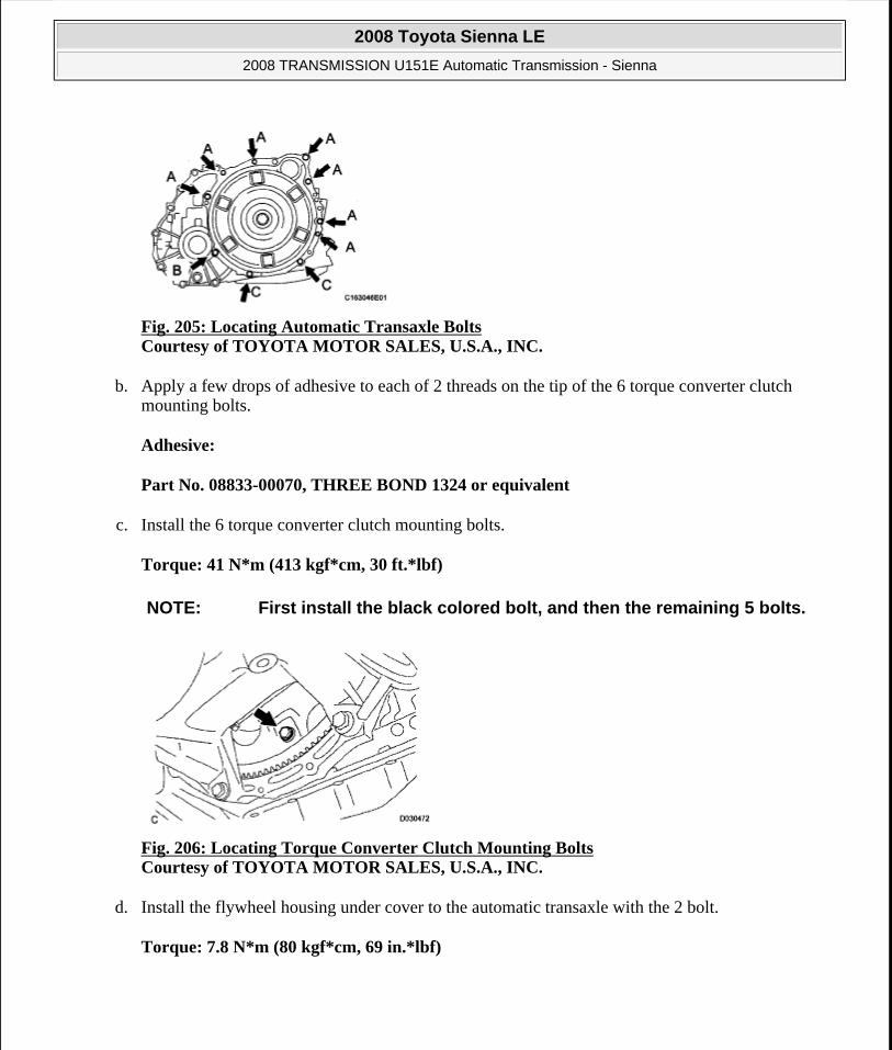
Fig. 205: Locating Automatic Transaxle Bolts Courtesy of TOYOTA MOTOR SALES, U.S.A., INC.
b. Apply a few drops of adhesive to each of 2 threads on the tip of the 6 torque converter clutch mounting bolts.
Adhesive:
Part No. 08833-00070, THREE BOND 1324 or equivalent
c. Install the 6 torque converter clutch mounting bolts.
Torque: 41 N*m (413 kgf*cm, 30 ft.*lbf)
Fig. 206: Locating Torque Converter Clutch Mounting Bolts Courtesy of TOYOTA MOTOR SALES, U.S.A., INC.
d. Install the flywheel housing under cover to the automatic transaxle with the 2 bolt.
Torque: 7.8 N*m (80 kgf*cm, 69 in.*lbf)
NOTE: First install the black colored bolt, and then the remaining 5 bolts.
2008 Toyota Sienna LE
2008 TRANSMISSION U151E Automatic Transmission - Sienna
Microsoft
Wednesday, August 12, 2009 2:03:27 PM Page 234 © 2005 Mitchell Repair Information Company, LLC.

Fig. 207: Locating Flywheel Housing Under Cover Bolts Courtesy of TOYOTA MOTOR SALES, U.S.A., INC.
3. INSTALL ENGINE MOUNTING BRACKET FRONT
a. Install the engine mounting bracket front to the automatic transaxle with the 3 bolts.
Torque: 64 N*m (653 kgf*cm, 47 ft.*lbf)
Fig. 208: Locating Engine Mounting Bracket Bolts (Front) Courtesy of TOYOTA MOTOR SALES, U.S.A., INC.
4. INSTALL TRANSMISSION OIL FILLER TUBE SUB-ASSEMBLY
a. Coat a new O-ring with ATF, and install it to the transmission oil filler tube sub-assembly.
b. Install the transmission oil filler tube sub-assembly and bolt to the automatic transaxle.
Torque: 5.5 N*m (56 kgf*cm, 49 in.*lbf)
2008 Toyota Sienna LE
2008 TRANSMISSION U151E Automatic Transmission - Sienna
Microsoft
Wednesday, August 12, 2009 2:03:27 PM Page 235 © 2005 Mitchell Repair Information Company, LLC.

Fig. 209: Locating Transmission Oil Filler Tube Bolt Courtesy of TOYOTA MOTOR SALES, U.S.A., INC.
c. Connect the 2 clamps to the oil filler tube.
d. Install the ATF level gauge.
5. INSTALL OIL COOLER INLET TUBE NO.1
a. Temporarily install the oil cooler outlet tube No.1.
b. Temporarily install the oil cooler inlet tube No.1.
c. Install the oil cooler tube clamp and bolt.
Torque: 5.5 N*m (56 kgf*cm, 49 in.*lbf)
Fig. 210: Locating Oil Cooler Tube Clamp Bolt Courtesy of TOYOTA MOTOR SALES, U.S.A., INC.
d. Using SST and a wrench, tighten the oil cooler inlet tube No.1.
SST 09023-12701
Torque: 34 N*m (347 kgf*cm, 25 ft.*lbf)
2008 Toyota Sienna LE
2008 TRANSMISSION U151E Automatic Transmission - Sienna
Microsoft
Wednesday, August 12, 2009 2:03:27 PM Page 236 © 2005 Mitchell Repair Information Company, LLC.

Fig. 211: Locating Oil Cooler Inlet Tube Courtesy of TOYOTA MOTOR SALES, U.S.A., INC.
6. INSTALL OIL COOLER OUTLET TUBE NO.1
a. Using SST and a wrench, tighten the oil cooler outlet tube No.1.
SST 09023-12701
Torque: 34 N*m (347 kgf*cm, 25 ft.*lbf)
7. INSTALL TRANSMISSION CONTROL CABLE BRACKET NO.1
a. Install the control cable bracket No.1 with the 2 bolts.
Torque: 12 N*m (122 kgf*cm, 9 ft.*lbf)
Fig. 212: Locating Control Cable Bracket Bolts Courtesy of TOYOTA MOTOR SALES, U.S.A., INC.
8. CONNECT CONNECTORS
a. Connect the transmission wire connector.
b. Connect the park/neutral position switch connector.
c. Connect the 2 speed sensor connectors.
2008 Toyota Sienna LE
2008 TRANSMISSION U151E Automatic Transmission - Sienna
Microsoft
Wednesday, August 12, 2009 2:03:27 PM Page 237 © 2005 Mitchell Repair Information Company, LLC.

Fig. 213: Identifying Park/Neutral Position Switch Connector And Speed Sensor ConnectorsCourtesy of TOYOTA MOTOR SALES, U.S.A., INC.
9. INSTALL STARTER ASSEMBLY
a. Install the starter assembly with the 2 bolts (1).
Torque: 37 N*m (377 kgf*cm, 27 ft.*lbf)
b. Connect the connector (2).
c. Connect the starter wire with the nut (3).
Torque: 9.8 N*m (100 kgf*cm, 87 in.*lbf)
Fig. 214: Locating Starter Assembly Bolts Courtesy of TOYOTA MOTOR SALES, U.S.A., INC.
2008 Toyota Sienna LE
2008 TRANSMISSION U151E Automatic Transmission - Sienna
Microsoft
Wednesday, August 12, 2009 2:03:27 PM Page 238 © 2005 Mitchell Repair Information Company, LLC.
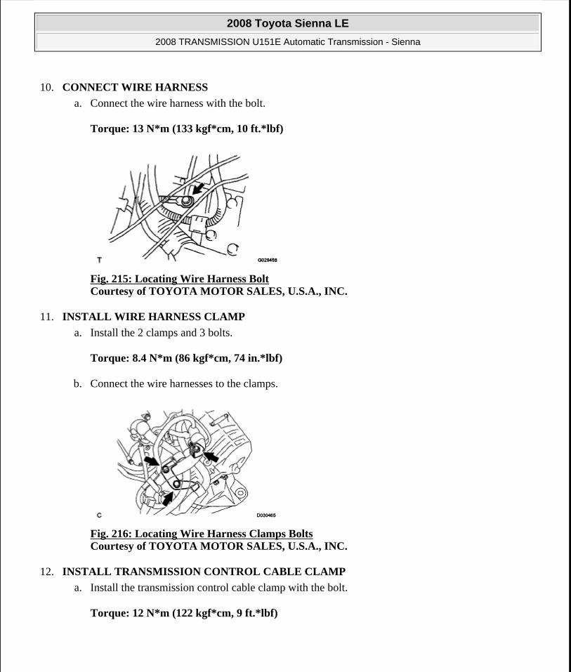
10. CONNECT WIRE HARNESS
a. Connect the wire harness with the bolt.
Torque: 13 N*m (133 kgf*cm, 10 ft.*lbf)
Fig. 215: Locating Wire Harness Bolt Courtesy of TOYOTA MOTOR SALES, U.S.A., INC.
11. INSTALL WIRE HARNESS CLAMP
a. Install the 2 clamps and 3 bolts.
Torque: 8.4 N*m (86 kgf*cm, 74 in.*lbf)
b. Connect the wire harnesses to the clamps.
Fig. 216: Locating Wire Harness Clamps Bolts Courtesy of TOYOTA MOTOR SALES, U.S.A., INC.
12. INSTALL TRANSMISSION CONTROL CABLE CLAMP
a. Install the transmission control cable clamp with the bolt.
Torque: 12 N*m (122 kgf*cm, 9 ft.*lbf)
2008 Toyota Sienna LE
2008 TRANSMISSION U151E Automatic Transmission - Sienna
Microsoft
Wednesday, August 12, 2009 2:03:27 PM Page 239 © 2005 Mitchell Repair Information Company, LLC.

Fig. 217: Locating Transmission Control Cable Bracket Bolt Courtesy of TOYOTA MOTOR SALES, U.S.A., INC.
13. INSTALL FRONT DRIVE SHAFT ASSEMBLY LH
HINT:
(See INSTALLATION )
14. INSTALL FRONT DRIVE SHAFT ASSEMBLY RH
HINT:
(See INSTALLATION )
15. INSTALL ENGINE ASSEMBLY WITH TRANSAXLE
HINT:
(See INSTALLATION )
16. RESET MEMORY
HINT:
(See INITIALIZATION )
TORQUE CONVERTER CLUTCH AND DRIVE PLATE
INSPECTION
1. INSPECT TORQUE CONVERTER CLUTCH ASSEMBLY
a. Inspect the one-way clutch.
1. Set SST into the inner race of the one-way clutch.
SST 09350-32014 (09351 -32010)
2008 Toyota Sienna LE
2008 TRANSMISSION U151E Automatic Transmission - Sienna
Microsoft
Wednesday, August 12, 2009 2:03:27 PM Page 240 © 2005 Mitchell Repair Information Company, LLC.

Fig. 218: Setting SST Into Inner Race Of One-Way Clutch Courtesy of TOYOTA MOTOR SALES, U.S.A., INC.
2. Install SST so that it fits in the notch of the converter hub and outer race of the one-way clutch.
SST 09350-32014 (09351 - 32010, 09351 - 32020)
3. Stand the torque converter up and turn the SST.
Standard:
If the one-way clutch is turned clockwise, it rotates freely and if turned counterclockwise, it locks.
Fig. 219: Inspecting Torque Converter Clutch Assembly Courtesy of TOYOTA MOTOR SALES, U.S.A., INC.
b. Determine the condition of the torque converter clutch assembly.
1. If the inspection result of the torque converter clutch assembly satisfies the following conditions, replace the torque converter clutch assembly.
Malfunction item:
A metallic sound is emitted from the torque converter clutch assembly during the stall test or when the shift lever is moved to the N position.
2008 Toyota Sienna LE
2008 TRANSMISSION U151E Automatic Transmission - Sienna
Microsoft
Wednesday, August 12, 2009 2:03:27 PM Page 241 © 2005 Mitchell Repair Information Company, LLC.

The one-way clutch is free or locked in both directions.
The amount of powder in the ATF is greater than the sample shown on the illustration (see Fig. 220 ).
HINT:
The illustration shows the auto fluid of approximately 0.25 liters (0.26 US qts, 0.22 Imp. qts) that is taken out from the removed torque converter clutch.
Fig. 220: Identifying Minimum Amount Of Powders In ATF Courtesy of TOYOTA MOTOR SALES, U.S.A., INC.
c. Exchange the ATF in the torque converter clutch.
1. If the ATF is discolored and/or has a foul odor, completely stir the ATF in the torque converter clutch and drain it with the torque converter facing up.
d. Clean and check the oil cooler and oil pipe line.
1. If the torque converter clutch is inspected or the ATF is exchanged, clean the oil cooler and oil pipe line.
HINT:
Spray compressed air of 196 kPa (2 kgf/cm 2, 28 psi) from the inlet hose.
If plenty of fine powders are identified in the ATF, add new ATF using a bucket pump and clean it again.
2008 Toyota Sienna LE
2008 TRANSMISSION U151E Automatic Transmission - Sienna
Microsoft
Wednesday, August 12, 2009 2:03:27 PM Page 242 © 2005 Mitchell Repair Information Company, LLC.
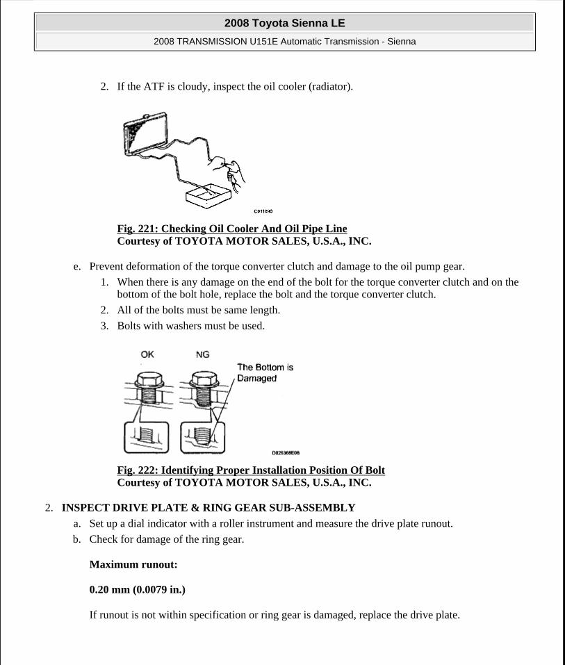
2. If the ATF is cloudy, inspect the oil cooler (radiator).
Fig. 221: Checking Oil Cooler And Oil Pipe Line Courtesy of TOYOTA MOTOR SALES, U.S.A., INC.
e. Prevent deformation of the torque converter clutch and damage to the oil pump gear.
1. When there is any damage on the end of the bolt for the torque converter clutch and on the bottom of the bolt hole, replace the bolt and the torque converter clutch.
2. All of the bolts must be same length.
3. Bolts with washers must be used.
Fig. 222: Identifying Proper Installation Position Of Bolt Courtesy of TOYOTA MOTOR SALES, U.S.A., INC.
2. INSPECT DRIVE PLATE & RING GEAR SUB-ASSEMBLY
a. Set up a dial indicator with a roller instrument and measure the drive plate runout.
b. Check for damage of the ring gear.
Maximum runout:
0.20 mm (0.0079 in.)
If runout is not within specification or ring gear is damaged, replace the drive plate.
2008 Toyota Sienna LE
2008 TRANSMISSION U151E Automatic Transmission - Sienna
Microsoft
Wednesday, August 12, 2009 2:03:27 PM Page 243 © 2005 Mitchell Repair Information Company, LLC.

Fig. 223: Measuring Drive Plate Runout Courtesy of TOYOTA MOTOR SALES, U.S.A., INC.
AUTOMATIC TRANSAXLE UNIT
COMPONENTS
Fig. 224: Identifying Automatic Transaxle Unit Components With Torque Specification (1 Of 5) Courtesy of TOYOTA MOTOR SALES, U.S.A., INC.
2008 Toyota Sienna LE
2008 TRANSMISSION U151E Automatic Transmission - Sienna
Microsoft
Wednesday, August 12, 2009 2:03:27 PM Page 244 © 2005 Mitchell Repair Information Company, LLC.

Fig. 225: Identifying Automatic Transaxle Unit Components With Torque Specification (2 Of 5) Courtesy of TOYOTA MOTOR SALES, U.S.A., INC.
2008 Toyota Sienna LE
2008 TRANSMISSION U151E Automatic Transmission - Sienna
Microsoft
Wednesday, August 12, 2009 2:03:27 PM Page 245 © 2005 Mitchell Repair Information Company, LLC.

Fig. 226: Identifying Automatic Transaxle Unit Components With Torque Specification (3 Of 5) Courtesy of TOYOTA MOTOR SALES, U.S.A., INC.
2008 Toyota Sienna LE
2008 TRANSMISSION U151E Automatic Transmission - Sienna
Microsoft
Wednesday, August 12, 2009 2:03:27 PM Page 246 © 2005 Mitchell Repair Information Company, LLC.

Fig. 227: Identifying Automatic Transaxle Unit Components (4 Of 5) Courtesy of TOYOTA MOTOR SALES, U.S.A., INC.
2008 Toyota Sienna LE
2008 TRANSMISSION U151E Automatic Transmission - Sienna
Microsoft
Wednesday, August 12, 2009 2:03:27 PM Page 247 © 2005 Mitchell Repair Information Company, LLC.
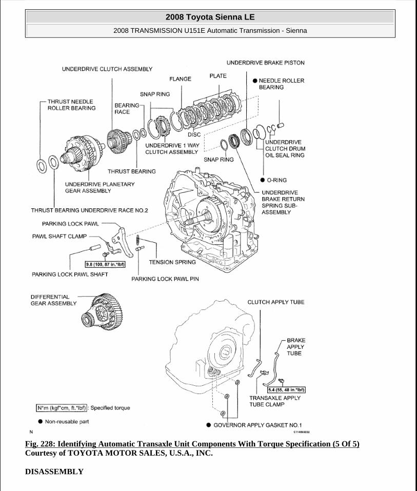
Fig. 228: Identifying Automatic Transaxle Unit Components With Torque Specification (5 Of 5) Courtesy of TOYOTA MOTOR SALES, U.S.A., INC.
DISASSEMBLY
2008 Toyota Sienna LE
2008 TRANSMISSION U151E Automatic Transmission - Sienna
Microsoft
Wednesday, August 12, 2009 2:03:27 PM Page 248 © 2005 Mitchell Repair Information Company, LLC.

1. REMOVE PARK/NEUTRAL POSITION SWITCH ASSEMBLY
a. Remove the nut, washer and control shaft lever.
Fig. 229: Locating Control Shaft Lever Nut Courtesy of TOYOTA MOTOR SALES, U.S.A., INC.
b. Using a screwdriver, unstake the nut stopper, and remove the lock nut and nut stopper.
Fig. 230: Unstaking Nut Stopper Courtesy of TOYOTA MOTOR SALES, U.S.A., INC.
c. Remove the 2 bolts and pull out the park/neutral position switch.
Fig. 231: Locating Park/Neutral Position Switch Bolts Courtesy of TOYOTA MOTOR SALES, U.S.A., INC.
2. REMOVE BREATHER PLUG HOSE
2008 Toyota Sienna LE
2008 TRANSMISSION U151E Automatic Transmission - Sienna
Microsoft
Wednesday, August 12, 2009 2:03:27 PM Page 249 © 2005 Mitchell Repair Information Company, LLC.
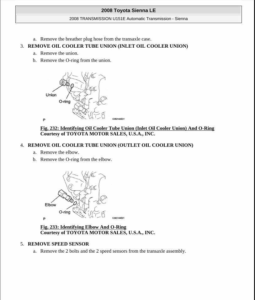
a. Remove the breather plug hose from the transaxle case.
3. REMOVE OIL COOLER TUBE UNION (INLET OIL COOLER UNION)
a. Remove the union.
b. Remove the O-ring from the union.
Fig. 232: Identifying Oil Cooler Tube Union (Inlet Oil Cooler Union) And O-Ring Courtesy of TOYOTA MOTOR SALES, U.S.A., INC.
4. REMOVE OIL COOLER TUBE UNION (OUTLET OIL COOLER UNION)
a. Remove the elbow.
b. Remove the O-ring from the elbow.
Fig. 233: Identifying Elbow And O-Ring Courtesy of TOYOTA MOTOR SALES, U.S.A., INC.
5. REMOVE SPEED SENSOR
a. Remove the 2 bolts and the 2 speed sensors from the transaxle assembly.
2008 Toyota Sienna LE
2008 TRANSMISSION U151E Automatic Transmission - Sienna
Microsoft
Wednesday, August 12, 2009 2:03:27 PM Page 250 © 2005 Mitchell Repair Information Company, LLC.

Fig. 234: Identifying Bolts And Speed Sensors Courtesy of TOYOTA MOTOR SALES, U.S.A., INC.
6. REMOVE TRANSAXLE CASE NO.1 PLUG
a. Remove the 4 transaxle case No.1 plugs from the transaxle case.
b. Remove the 4 O-rings from the 4 transaxle case No.1 plugs.
Fig. 235: Identifying O-Rings And Transaxle Case No.1 Plugs Courtesy of TOYOTA MOTOR SALES, U.S.A., INC.
7. FIX AUTOMATIC TRANSAXLE ASSEMBLY
a. Fix the transaxle assembly.
Fig. 236: Fixing Automatic Transaxle Assembly Courtesy of TOYOTA MOTOR SALES, U.S.A., INC.
8. REMOVE AUTOMATIC TRANSAXLE OIL PAN SUB-ASSEMBLY
2008 Toyota Sienna LE
2008 TRANSMISSION U151E Automatic Transmission - Sienna
Microsoft
Wednesday, August 12, 2009 2:03:27 PM Page 251 © 2005 Mitchell Repair Information Company, LLC.

a. Remove the 18 bolts, oil pan and gasket.
Fig. 237: Locating Oil Pan Bolts Courtesy of TOYOTA MOTOR SALES, U.S.A., INC.
b. Remove the 2 magnets from the oil pan.
Fig. 238: Locating Magnets In Oil Pan Courtesy of TOYOTA MOTOR SALES, U.S.A., INC.
9. INSPECT TRANSMISSION OIL CLEANER MAGNET
a. Remove the magnets and use them to collect any steel chips. Examine the chips and particles in the pan and on the magnet to determine what type of wear has occurred in the transaxle:
Result:
Steel (magnetic):
Wear of the bearing, gear and plate
Brass (non-magnetic):
Wear of the bushing
2008 Toyota Sienna LE
2008 TRANSMISSION U151E Automatic Transmission - Sienna
Microsoft
Wednesday, August 12, 2009 2:03:27 PM Page 252 © 2005 Mitchell Repair Information Company, LLC.

Fig. 239: Collecting Steel Chips Using Magnet Courtesy of TOYOTA MOTOR SALES, U.S.A., INC.
10. DISCONNECT TRANSMISSION WIRE
a. Remove the 7 connectors from the shift solenoid valves.
b. Remove the bolt, lock plate and temperature sensor.
Fig. 240: Locating Shift Solenoid Valves Connectors Courtesy of TOYOTA MOTOR SALES, U.S.A., INC.
11. REMOVE TRANSMISSION WIRE
a. Remove the bolt and transmission wire from the transaxle case.
Fig. 241: Identifying Transmission Wire Courtesy of TOYOTA MOTOR SALES, U.S.A., INC.
12. REMOVE VALVE BODY OIL STRAINER ASSEMBLY
2008 Toyota Sienna LE
2008 TRANSMISSION U151E Automatic Transmission - Sienna
Microsoft
Wednesday, August 12, 2009 2:03:27 PM Page 253 © 2005 Mitchell Repair Information Company, LLC.

a. Remove the 3 bolts and oil strainer.
Fig. 242: Locating Oil Strainer Bolts Courtesy of TOYOTA MOTOR SALES, U.S.A., INC.
b. Remove the O-ring from the oil strainer.
Fig. 243: Locating Oil Strainer O-Ring Courtesy of TOYOTA MOTOR SALES, U.S.A., INC.
13. REMOVE TRANSMISSION VALVE BODY ASSEMBLY
a. Support the valve body assembly and remove the 17 bolts and valve body assembly.
Fig. 244: Locating Valve Body Assembly Bolts Courtesy of TOYOTA MOTOR SALES, U.S.A., INC.
2008 Toyota Sienna LE
2008 TRANSMISSION U151E Automatic Transmission - Sienna
Microsoft
Wednesday, August 12, 2009 2:03:27 PM Page 254 © 2005 Mitchell Repair Information Company, LLC.

14. REMOVE GOVERNOR APPLY GASKET NO.1
a. Remove the governor apply gasket No.1 from the transaxle case.
Fig. 245: Locating Governor Apply Gasket Courtesy of TOYOTA MOTOR SALES, U.S.A., INC.
15. REMOVE TRANSAXLE CASE 2ND BRAKE GASKET
a. Remove the transaxle case 2nd brake gasket from the transaxle case.
Fig. 246: Locating Transaxle Case 2nd Brake Gasket Courtesy of TOYOTA MOTOR SALES, U.S.A., INC.
16. REMOVE BRAKE DRUM GASKET
a. Remove the brake drum gasket from the transaxle case.
Fig. 247: Locating Brake Drum Gasket Courtesy of TOYOTA MOTOR SALES, U.S.A., INC.
2008 Toyota Sienna LE
2008 TRANSMISSION U151E Automatic Transmission - Sienna
Microsoft
Wednesday, August 12, 2009 2:03:27 PM Page 255 © 2005 Mitchell Repair Information Company, LLC.
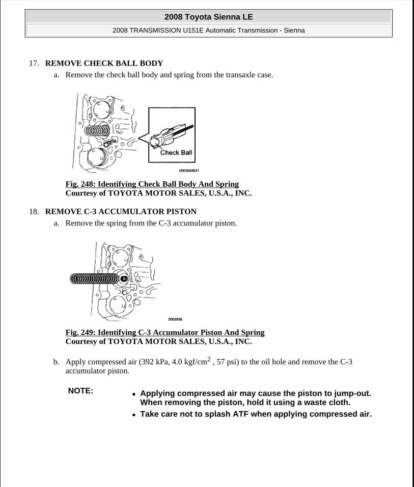
17. REMOVE CHECK BALL BODY
a. Remove the check ball body and spring from the transaxle case.
Fig. 248: Identifying Check Ball Body And Spring Courtesy of TOYOTA MOTOR SALES, U.S.A., INC.
18. REMOVE C-3 ACCUMULATOR PISTON
a. Remove the spring from the C-3 accumulator piston.
Fig. 249: Identifying C-3 Accumulator Piston And Spring Courtesy of TOYOTA MOTOR SALES, U.S.A., INC.
b. Apply compressed air (392 kPa, 4.0 kgf/cm2 , 57 psi) to the oil hole and remove the C-3 accumulator piston.
NOTE: Applying compressed air may cause the piston to jump-out. When removing the piston, hold it using a waste cloth.
Take care not to splash ATF when applying compressed air.
2008 Toyota Sienna LE
2008 TRANSMISSION U151E Automatic Transmission - Sienna
Microsoft
Wednesday, August 12, 2009 2:03:27 PM Page 256 © 2005 Mitchell Repair Information Company, LLC.

c. Remove the O-ring from the C-3 accumulator piston.
Fig. 251: Locating C-3 Accumulator Piston O-Ring Courtesy of TOYOTA MOTOR SALES, U.S.A., INC.
19. REMOVE REVERSE CLUTCH ACCUMULATOR PISTON
a. Apply compressed air (392 kPa, 4.0 kgf/cm2 , 57 psi) to the oil hole and remove the reverse accumulator piston and spring.
Fig. 250: Locating C-3 Accumulator Piston Courtesy of TOYOTA MOTOR SALES, U.S.A., INC.
NOTE: Applying compressed air may cause the piston to jump-out. When removing the piston, hold it using a waste cloth.
Take care not to splash ATF when applying compressed air.
2008 Toyota Sienna LE
2008 TRANSMISSION U151E Automatic Transmission - Sienna
Microsoft
Wednesday, August 12, 2009 2:03:27 PM Page 257 © 2005 Mitchell Repair Information Company, LLC.

b. Remove the 2 O-rings from the reverse clutch accumulator piston.
Fig. 253: Locating Reverse Clutch Accumulator Piston O-Rings Courtesy of TOYOTA MOTOR SALES, U.S.A., INC.
20. REMOVE B-3 ACCUMULATOR PISTON
a. Apply compressed air (392 kPa, 4.0 kgf/cm2 , 57 psi) to the oil hole and remove the B-3 accumulator piston and 2 springs.
b. Remove the O-ring from the B-3 accumulator piston.
Fig. 252: Locating Reverse Accumulator Piston And Spring Courtesy of TOYOTA MOTOR SALES, U.S.A., INC.
NOTE: Applying compressed air may cause the piston to jump-out. When removing the piston, hold it using a waste cloth.
Take care not to splash ATF when applying compressed air.
Fig. 254: Locating B-3 Accumulator Piston Courtesy of TOYOTA MOTOR SALES, U.S.A., INC.
2008 Toyota Sienna LE
2008 TRANSMISSION U151E Automatic Transmission - Sienna
Microsoft
Wednesday, August 12, 2009 2:03:27 PM Page 258 © 2005 Mitchell Repair Information Company, LLC.
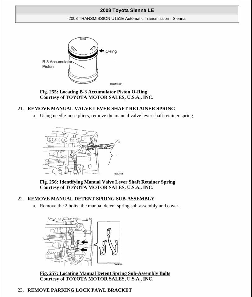
Fig. 255: Locating B-3 Accumulator Piston O-Ring Courtesy of TOYOTA MOTOR SALES, U.S.A., INC.
21. REMOVE MANUAL VALVE LEVER SHAFT RETAINER SPRING
a. Using needle-nose pliers, remove the manual valve lever shaft retainer spring.
Fig. 256: Identifying Manual Valve Lever Shaft Retainer Spring Courtesy of TOYOTA MOTOR SALES, U.S.A., INC.
22. REMOVE MANUAL DETENT SPRING SUB-ASSEMBLY
a. Remove the 2 bolts, the manual detent spring sub-assembly and cover.
Fig. 257: Locating Manual Detent Spring Sub-Assembly Bolts Courtesy of TOYOTA MOTOR SALES, U.S.A., INC.
23. REMOVE PARKING LOCK PAWL BRACKET
2008 Toyota Sienna LE
2008 TRANSMISSION U151E Automatic Transmission - Sienna
Microsoft
Wednesday, August 12, 2009 2:03:27 PM Page 259 © 2005 Mitchell Repair Information Company, LLC.

a. Remove the 2 bolts and parking lock pawl bracket.
Fig. 258: Locating Parking Lock Pawl Bracket Bolts Courtesy of TOYOTA MOTOR SALES, U.S.A., INC.
24. REMOVE MANUAL VALVE LEVER SUB-ASSEMBLY
a. Using a chisel and hammer, cut off and remove the spacer.
Fig. 259: Removing Spacer Using Chisel And Hammer Courtesy of TOYOTA MOTOR SALES, U.S.A., INC.
b. Using a pin punch (ø35 mm) and hammer, drive out the pin.
HINT:
Slowly drive out the pin so that it will not fall into the transaxle case.
2008 Toyota Sienna LE
2008 TRANSMISSION U151E Automatic Transmission - Sienna
Microsoft
Wednesday, August 12, 2009 2:03:27 PM Page 260 © 2005 Mitchell Repair Information Company, LLC.

Fig. 260: Locating Pin Courtesy of TOYOTA MOTOR SALES, U.S.A., INC.
c. Remove the manual valve lever shaft and manual valve lever.
Fig. 261: Identifying Manual Valve Lever Shaft And Lever Courtesy of TOYOTA MOTOR SALES, U.S.A., INC.
25. REMOVE PARKING LOCK ROD SUB-ASSEMBLY
a. Remove the parking lock rod from the manual valve lever.
Fig. 262: Identifying Parking Lock Rod Sub-Assembly Courtesy of TOYOTA MOTOR SALES, U.S.A., INC.
26. REMOVE MANUAL VALVE LEVER SHAFT OIL SEAL
a. Using a screwdriver, remove the oil seal from the transaxle case.
NOTE: Do not apply excessive force when removing the oil seal.
2008 Toyota Sienna LE
2008 TRANSMISSION U151E Automatic Transmission - Sienna
Microsoft
Wednesday, August 12, 2009 2:03:28 PM Page 261 © 2005 Mitchell Repair Information Company, LLC.

Fig. 263: Removing Manual Valve Lever Shaft Oil Seal Using Screwdriver Courtesy of TOYOTA MOTOR SALES, U.S.A., INC.
27. FIX AUTOMATIC TRANSAXLE ASSEMBLY
a. Fix the transaxle case with the oil pump side facing up.
28. INSPECT INPUT SHAFT ENDPLAY
HINT:
(See INSPECTION )
29. REMOVE TRANSAXLE HOUSING
a. Remove the 16 bolts.
b. Tap on the circumference of the transaxle housing with a plastic hammer to remove the transaxle housing from the transaxle case.
Fig. 264: Locating Transaxle Housing Bolts Courtesy of TOYOTA MOTOR SALES, U.S.A., INC.
30. REMOVE OIL PUMP ASSEMBLY
a. Remove the 7 bolts and oil pump from the transaxle case.
NOTE: The differential may be accidentally removed when the transaxle housing is removed.
2008 Toyota Sienna LE
2008 TRANSMISSION U151E Automatic Transmission - Sienna
Microsoft
Wednesday, August 12, 2009 2:03:28 PM Page 262 © 2005 Mitchell Repair Information Company, LLC.

Fig. 265: Locating Oil Pump Assembly Bolts Courtesy of TOYOTA MOTOR SALES, U.S.A., INC.
31. REMOVE THRUST NEEDLE ROLLER BEARING
a. Remove the thrust needle roller bearing from the underdrive planetary gear assembly.
Fig. 266: Identifying Thrust Needle Roller Bearing And Forward Clutch Assembly Courtesy of TOYOTA MOTOR SALES, U.S.A., INC.
32. REMOVE THRUST BEARING UNDERDRIVE RACE NO.2
a. Remove the thrust bearing underdrive race No.2 from the underdrive planetary gear assembly.
Fig. 267: Identifying Differential Gear Assembly, Underdrive Planetary Gear Assembly And Forward Clutch Assembly Courtesy of TOYOTA MOTOR SALES, U.S.A., INC.
33. REMOVE DIFFERENTIAL GEAR ASSEMBLY
2008 Toyota Sienna LE
2008 TRANSMISSION U151E Automatic Transmission - Sienna
Microsoft
Wednesday, August 12, 2009 2:03:28 PM Page 263 © 2005 Mitchell Repair Information Company, LLC.
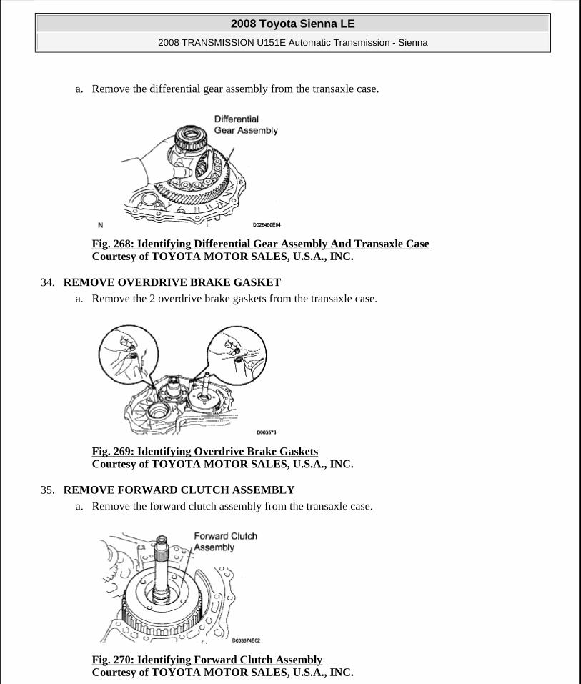
a. Remove the differential gear assembly from the transaxle case.
Fig. 268: Identifying Differential Gear Assembly And Transaxle Case Courtesy of TOYOTA MOTOR SALES, U.S.A., INC.
34. REMOVE OVERDRIVE BRAKE GASKET
a. Remove the 2 overdrive brake gaskets from the transaxle case.
Fig. 269: Identifying Overdrive Brake Gaskets Courtesy of TOYOTA MOTOR SALES, U.S.A., INC.
35. REMOVE FORWARD CLUTCH ASSEMBLY
a. Remove the forward clutch assembly from the transaxle case.
Fig. 270: Identifying Forward Clutch Assembly Courtesy of TOYOTA MOTOR SALES, U.S.A., INC.
2008 Toyota Sienna LE
2008 TRANSMISSION U151E Automatic Transmission - Sienna
Microsoft
Wednesday, August 12, 2009 2:03:28 PM Page 264 © 2005 Mitchell Repair Information Company, LLC.

b. Remove the thrust needle roller bearing from the forward clutch.
Fig. 271: Identifying Thrust Needle Roller Bearing Courtesy of TOYOTA MOTOR SALES, U.S.A., INC.
36. REMOVE MULTIPLE DISC CLUTCH HUB
a. Remove the thrust needle roller bearing, multiple disc clutch hub, thrust needle roller bearing and thrust bearing race No.1 from the transaxle case.
Fig. 272: Identifying Thrust Needle Roller Bearing, Multiple Disc Clutch Hub And Thrust Bearing Race Courtesy of TOYOTA MOTOR SALES, U.S.A., INC.
37. INSPECT MULTIPLE DISC CLUTCH HUB
HINT:
(See INSPECTION )
38. REMOVE UNDERDRIVE PLANETARY GEAR ASSEMBLY
a. Remove the bolt and pawl shaft clamp.
2008 Toyota Sienna LE
2008 TRANSMISSION U151E Automatic Transmission - Sienna
Microsoft
Wednesday, August 12, 2009 2:03:28 PM Page 265 © 2005 Mitchell Repair Information Company, LLC.

Fig. 273: Identifying Bolt And Pawl Shaft Clamp Courtesy of TOYOTA MOTOR SALES, U.S.A., INC.
b. Remove the parking lock pawl shaft.
Fig. 274: Locating Parking Lock Pawl Shaft Courtesy of TOYOTA MOTOR SALES, U.S.A., INC.
c. Push the parking lock pawl.
HINT:
Failure to do so will cause interference when the underdrive planetary gear is removed.
Fig. 275: Identifying Parking Lock Pawl Courtesy of TOYOTA MOTOR SALES, U.S.A., INC.
2008 Toyota Sienna LE
2008 TRANSMISSION U151E Automatic Transmission - Sienna
Microsoft
Wednesday, August 12, 2009 2:03:28 PM Page 266 © 2005 Mitchell Repair Information Company, LLC.

d. Remove the underdrive planetary gear assembly from the transaxle case.
Fig. 276: Identifying Underdrive Planetary Gear Assembly Courtesy of TOYOTA MOTOR SALES, U.S.A., INC.
39. REMOVE PARKING LOCK PAWL
a. Remove the spring, pawl pin and parking lock pawl.
Fig. 277: Identifying Spring And Parking Lock Pawl Courtesy of TOYOTA MOTOR SALES, U.S.A., INC.
40. REMOVE UNDERDRIVE CLUTCH ASSEMBLY
a. Remove the underdrive clutch assembly, thrust bearing and bearing race from the transaxle case.
NOTE: Be careful so that the underdrive planetary gear assembly will not fall out.
2008 Toyota Sienna LE
2008 TRANSMISSION U151E Automatic Transmission - Sienna
Microsoft
Wednesday, August 12, 2009 2:03:28 PM Page 267 © 2005 Mitchell Repair Information Company, LLC.

Fig. 278: Identifying Thrust Bearing And Bearing Race Courtesy of TOYOTA MOTOR SALES, U.S.A., INC.
41. REMOVE UNDERDRIVE 1-WAY CLUTCH ASSEMBLY
a. Using a screwdriver, remove the snap ring from the transaxle case.
Fig. 279: Identifying Snap Ring Courtesy of TOYOTA MOTOR SALES, U.S.A., INC.
b. Remove the underdrive 1-way clutch from the transaxle case.
Fig. 280: Identifying Underdrive 1-Way Clutch Courtesy of TOYOTA MOTOR SALES, U.S.A., INC.
NOTE: Do not apply excessive force when removing the snap ring.
2008 Toyota Sienna LE
2008 TRANSMISSION U151E Automatic Transmission - Sienna
Microsoft
Wednesday, August 12, 2009 2:03:28 PM Page 268 © 2005 Mitchell Repair Information Company, LLC.

c. Remove the outer race retainer from the 1 -way clutch.
Fig. 281: Identifying Outer Race Retainer Courtesy of TOYOTA MOTOR SALES, U.S.A., INC.
42. REMOVE UNDERDRIVE CLUTCH DISC NO.2
a. Using a screwdriver, remove the snap ring.
Fig. 282: Identifying Snap Ring Courtesy of TOYOTA MOTOR SALES, U.S.A., INC.
b. Remove the flange, 4 discs and 4 plates from the transaxle case.
43. INSPECT UNDERDRIVE CLUTCH DISC NO.2
HINT:
(See INSPECTION )
NOTE: Do not apply excessive force when removing the snap ring.
2008 Toyota Sienna LE
2008 TRANSMISSION U151E Automatic Transmission - Sienna
Microsoft
Wednesday, August 12, 2009 2:03:28 PM Page 269 © 2005 Mitchell Repair Information Company, LLC.

Fig. 283: Identifying Flange Courtesy of TOYOTA MOTOR SALES, U.S.A., INC.
44. REMOVE TRANSAXLE REAR COVER SUB-ASSEMBLY
a. Remove the 11 bolts.
b. Tap on the circumference of the rear cover with a plastic hammer to remove the transaxle rear cover from the transaxle case.
Fig. 284: Locating Transaxle Rear Cover Bolts Courtesy of TOYOTA MOTOR SALES, U.S.A., INC.
45. REMOVE TRANSAXLE CASE NO.1 PLUG
a. Remove the 4 transaxle case No.1 plugs from the transaxle rear cover.
b. Remove the 4 O-rings from the 4 transaxle case No.1 plugs.
Fig. 285: Identifying O-Ring And Transaxle Case No. 1 Plugs Courtesy of TOYOTA MOTOR SALES, U.S.A., INC.
2008 Toyota Sienna LE
2008 TRANSMISSION U151E Automatic Transmission - Sienna
Microsoft
Wednesday, August 12, 2009 2:03:28 PM Page 270 © 2005 Mitchell Repair Information Company, LLC.

46. REMOVE REAR CLUTCH OIL SEAL RING OUTER
a. Remove the 3 rear clutch oil seal rings from the transaxle rear cover.
Fig. 286: Identifying Rear Clutch Oil Seal Ring Outer Courtesy of TOYOTA MOTOR SALES, U.S.A., INC.
47. REMOVE NEEDLE-ROLLER BEARING
a. Using SST, remove the needle-roller bearing from the transaxle rear cover.
SST 09387-00041 (09387-01021, 09387-01030, 09387-01040)
Fig. 287: Identifying Needle-Roller Bearing And SST Courtesy of TOYOTA MOTOR SALES, U.S.A., INC.
48. REMOVE GOVERNOR APPLY GASKET NO.1
a. Using a screwdriver, remove the 3 apply gaskets.
2008 Toyota Sienna LE
2008 TRANSMISSION U151E Automatic Transmission - Sienna
Microsoft
Wednesday, August 12, 2009 2:03:28 PM Page 271 © 2005 Mitchell Repair Information Company, LLC.

Fig. 288: Locating Governor Apply GasketsCourtesy of TOYOTA MOTOR SALES, U.S.A., INC.
49. REMOVE BRAKE APPLY TUBE
a. Remove the bolt, clamp and brake apply tube.
b. Remove the clutch apply tube.
c. Remove the brake apply tube from the clamp.
Fig. 289: Identifying Brake Apply Tube And Clutch Apply Tube Courtesy of TOYOTA MOTOR SALES, U.S.A., INC.
50. REMOVE DIRECT CLUTCH ASSEMBLY
a. Remove the thrust bearing and the direct clutch assembly from the transaxle case.
Fig. 290: Identifying Thrust Bearing And Direct Clutch Assembly Courtesy of TOYOTA MOTOR SALES, U.S.A., INC.
51. REMOVE OVERDRIVE DIRECT CLUTCH HUB SUB-ASSEMBLY
a. Remove the thrust bearing race, thrust bearing and overdrive direct clutch hub from the planetary gear assembly.
NOTE: Do not bend the tubes.
2008 Toyota Sienna LE
2008 TRANSMISSION U151E Automatic Transmission - Sienna
Microsoft
Wednesday, August 12, 2009 2:03:28 PM Page 272 © 2005 Mitchell Repair Information Company, LLC.

Fig. 291: Identifying Thrust Bearing Race, Thrust Bearing And Overdrive Direct Clutch HubCourtesy of TOYOTA MOTOR SALES, U.S.A., INC.
52. INSPECT OVERDRIVE DIRECT CLUTCH DRUM SUB-ASSEMBLY
HINT:
(See INSPECTION )
53. REMOVE REAR PLANETARY SUN GEAR ASSEMBLY
a. Remove the rear planetary sun gear assembly from the transaxle case.
Fig. 292: Identifying Rear Planetary Sun Gear Assembly Courtesy of TOYOTA MOTOR SALES, U.S.A., INC.
b. Remove the thrust needle roller bearing and thrust bearing race from the rear planetary sun gear assembly.
2008 Toyota Sienna LE
2008 TRANSMISSION U151E Automatic Transmission - Sienna
Microsoft
Wednesday, August 12, 2009 2:03:28 PM Page 273 © 2005 Mitchell Repair Information Company, LLC.

Fig. 293: Identifying Thrust Needle Roller Bearing And Thrust Bearing Race Courtesy of TOYOTA MOTOR SALES, U.S.A., INC.
c. Remove the planetary carrier thrust washer No.2 from the rear planetary sun gear assembly.
Fig. 294: Identifying Planetary Carrier Thrust Washer And Rear Planetary Sun Gear Assembly Courtesy of TOYOTA MOTOR SALES, U.S.A., INC.
54. REMOVE 1-WAY CLUTCH ASSEMBLY
a. Remove the 1-way clutch assembly and the thrust needle roller bearing from the transaxle case.
Fig. 295: Identifying 1-Way Clutch Assembly And Thrust Needle Roller Bearing Courtesy of TOYOTA MOTOR SALES, U.S.A., INC.
b. Remove the 1-way clutch inner race from the 1-way clutch assembly.
2008 Toyota Sienna LE
2008 TRANSMISSION U151E Automatic Transmission - Sienna
Microsoft
Wednesday, August 12, 2009 2:03:28 PM Page 274 © 2005 Mitchell Repair Information Company, LLC.

Fig. 296: Identifying 1-Way Clutch Inner Race Courtesy of TOYOTA MOTOR SALES, U.S.A., INC.
55. REMOVE 1-WAY CLUTCH SLEEVE OUTER
a. Remove the 1 -way clutch sleeve outer from the transaxle case.
Fig. 297: Identifying 1-Way Clutch Sleeve Outer Courtesy of TOYOTA MOTOR SALES, U.S.A., INC.
56. REMOVE PLANETARY CARRIER THRUST WASHER NO.1
a. Remove the planetary carrier thrust washer No.1 from the planetary gear assembly.
Fig. 298: Identifying Planetary Carrier Thrust Washer Courtesy of TOYOTA MOTOR SALES, U.S.A., INC.
57. REMOVE 2ND BRAKE CLUTCH DISC
2008 Toyota Sienna LE
2008 TRANSMISSION U151E Automatic Transmission - Sienna
Microsoft
Wednesday, August 12, 2009 2:03:28 PM Page 275 © 2005 Mitchell Repair Information Company, LLC.
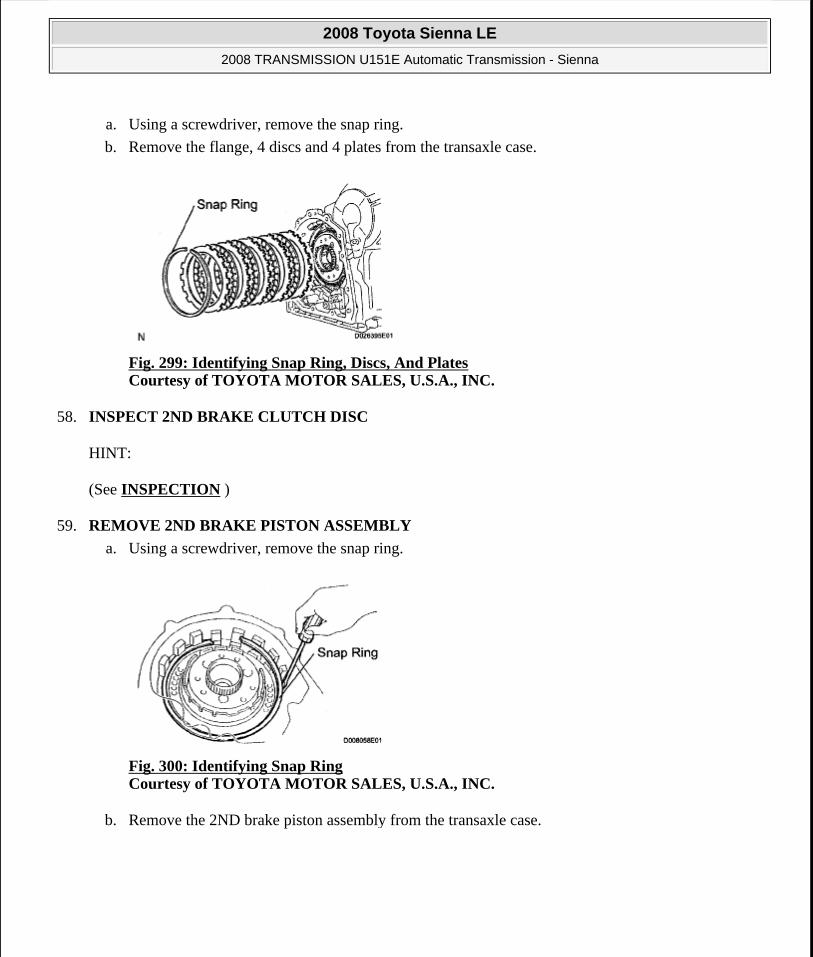
a. Using a screwdriver, remove the snap ring.
b. Remove the flange, 4 discs and 4 plates from the transaxle case.
Fig. 299: Identifying Snap Ring, Discs, And Plates Courtesy of TOYOTA MOTOR SALES, U.S.A., INC.
58. INSPECT 2ND BRAKE CLUTCH DISC
HINT:
(See INSPECTION )
59. REMOVE 2ND BRAKE PISTON ASSEMBLY
a. Using a screwdriver, remove the snap ring.
Fig. 300: Identifying Snap Ring Courtesy of TOYOTA MOTOR SALES, U.S.A., INC.
b. Remove the 2ND brake piston assembly from the transaxle case.
2008 Toyota Sienna LE
2008 TRANSMISSION U151E Automatic Transmission - Sienna
Microsoft
Wednesday, August 12, 2009 2:03:28 PM Page 276 © 2005 Mitchell Repair Information Company, LLC.

Fig. 301: Identifying 2nd Brake Piston Assembly Courtesy of TOYOTA MOTOR SALES, U.S.A., INC.
60. REMOVE REAR PLANETARY GEAR ASSEMBLY
a. Using a screwdriver, remove the snap ring.
Fig. 302: Identifying Snap Ring Courtesy of TOYOTA MOTOR SALES, U.S.A., INC.
b. Remove the rear planetary gear assembly from the transaxle case.
Fig. 303: Identifying Rear Planetary Gear Assembly Courtesy of TOYOTA MOTOR SALES, U.S.A., INC.
61. REMOVE INPUT SUN GEAR
a. Remove the 2 thrust needle roller bearings, thrust bearing race No.2 and the input sun gear from the
2008 Toyota Sienna LE
2008 TRANSMISSION U151E Automatic Transmission - Sienna
Microsoft
Wednesday, August 12, 2009 2:03:28 PM Page 277 © 2005 Mitchell Repair Information Company, LLC.

transaxle case.
Fig. 304: Identifying Thrust Needle Roller Bearings, Thrust Bearing Race And Input Sun Gear Courtesy of TOYOTA MOTOR SALES, U.S.A., INC.
62. REMOVE 1ST AND REVERSE BRAKE CLUTCH DISC
a. Remove the flange, 6 discs and 6 plates from the transaxle case.
Fig. 305: Identifying Flange, Discs And Plates Courtesy of TOYOTA MOTOR SALES, U.S.A., INC.
63. INSPECT 1ST AND REVERSE BRAKE CLUTCH DISC
HINT:
(See INSPECTION )
64. REMOVE FRONT PLANETARY GEAR ASSEMBLY
a. Using a chisel and hammer, unstake the lock washer.
NOTE: Push down all claws of the washer. Otherwise the SST cannot be fully pressed against the nut, and cannot loosen the nut.
2008 Toyota Sienna LE
2008 TRANSMISSION U151E Automatic Transmission - Sienna
Microsoft
Wednesday, August 12, 2009 2:03:28 PM Page 278 © 2005 Mitchell Repair Information Company, LLC.

Fig. 306: Using Chisel And Hammer To Unstake Lock Washer Courtesy of TOYOTA MOTOR SALES, U.S.A., INC.
b. Using SST, remove the nut.
SST 09387-00030,09387-00080
Fig. 307: Removing/Installing Front Planetary Gear Nut With SST Courtesy of TOYOTA MOTOR SALES, U.S.A., INC.
c. Using SST and a press, remove the front planetary gear assembly from the counter drive gear.
SST 09950-60010 (09951 -00450), 09950-70010 (09951-07100)
Fig. 308: Identifying Front Planetary Gear Assembly, Counter Drive Gear, And SST Courtesy of TOYOTA MOTOR SALES, U.S.A., INC.
d. Remove the front planetary gear assembly from the brake hub.
2008 Toyota Sienna LE
2008 TRANSMISSION U151E Automatic Transmission - Sienna
Microsoft
Wednesday, August 12, 2009 2:03:28 PM Page 279 © 2005 Mitchell Repair Information Company, LLC.

Fig. 309: View Of Front Planetary Gear Assembly And Brake Hub Courtesy of TOYOTA MOTOR SALES, U.S.A., INC.
65. REMOVE FRONT PLANETARY RING GEAR
a. Using a screwdriver, remove the snap ring and front planetary ring gear from the brake hub.
Fig. 310: Identifying Snap Ring, Brake Hub And Front Planetary Ring Gear Courtesy of TOYOTA MOTOR SALES, U.S.A., INC.
66. REMOVE 1ST AND REVERSE BRAKE RETURN SPRING SUB-ASSEMBLY
a. Place SST on the return spring, and compress the return spring with a press.
SST 09387-00070
b. Using a snap ring expander, remove the snap ring.
NOTE: Stop the press when the spring seat is lowered 1 to 2 mm (0.039 to 0.078 in.) from the snap ring groove, to prevent the spring seat from being deformed.
Do not expand the snap ring excessively.
2008 Toyota Sienna LE
2008 TRANSMISSION U151E Automatic Transmission - Sienna
Microsoft
Wednesday, August 12, 2009 2:03:28 PM Page 280 © 2005 Mitchell Repair Information Company, LLC.

67. INSPECT 1ST AND REVERSE BRAKE RETURN SPRING SUB-ASSEMBLY
HINT:
(See INSPECTION )
68. REMOVE 1ST AND REVERSE BRAKE PISTON
a. Apply compressed air (392 kPa, 40 kgf/cm2 , 57 psi) to the transaxle case to remove the 1st and reverse brake piston.
b. Remove the 2 O-rings from the 1st and reverse brake piston.
Fig. 311: Compressing Return Spring Using SST Courtesy of TOYOTA MOTOR SALES, U.S.A., INC.
NOTE: Applying compressed air may cause the piston to jump-out. When removing the piston, hold it using a waste cloth.
Take care not to splash ATF when applying compressed air.
Fig. 312: Identifying 1st And Reverse Brake Piston Courtesy of TOYOTA MOTOR SALES, U.S.A., INC.
2008 Toyota Sienna LE
2008 TRANSMISSION U151E Automatic Transmission - Sienna
Microsoft
Wednesday, August 12, 2009 2:03:28 PM Page 281 © 2005 Mitchell Repair Information Company, LLC.

Fig. 313: Locating 1st And Reverse Brake Piston O-Rings Courtesy of TOYOTA MOTOR SALES, U.S.A., INC.
69. REMOVE COUNTER DRIVE GEAR
a. Using SST and a press, remove the counter drive gear from the transaxle case.
SST 09950-60010 (09951-00590), 09950-70010 (09951-07100)
Fig. 314: Identifying Counter Drive Gear And SST Courtesy of TOYOTA MOTOR SALES, U.S.A., INC.
b. As shown in the illustration, tighten the 2 bolts evenly and make clearance of approx. 20.0 mm (0.787 in.) between the counter drive gear and the inner race.
Fig. 315: Identifying Clearance Between Counter Drive Gear And Inner Race Courtesy of TOYOTA MOTOR SALES, U.S.A., INC.
c. Using SST, remove the tapered roller bearing.
2008 Toyota Sienna LE
2008 TRANSMISSION U151E Automatic Transmission - Sienna
Microsoft
Wednesday, August 12, 2009 2:03:28 PM Page 282 © 2005 Mitchell Repair Information Company, LLC.

SST 09950-60010 (09951-00590), 09950-00020, 09950-00030, 09950-40011 (09957-04010)
Fig. 316: Identifying Tapered Roller Bearing And SST Courtesy of TOYOTA MOTOR SALES, U.S.A., INC.
70. REMOVE TRANSFER DRIVEN PINION FRONT BEARING
a. Using a snap ring expander, remove the snap ring.
Fig. 317: Identifying Snap Ring Courtesy of TOYOTA MOTOR SALES, U.S.A., INC.
b. Using SST and a press, remove the bearing outer race.
SST 09950-60020(09951-00910)
Fig. 318: Identifying Bearing Outer Race And SST Courtesy of TOYOTA MOTOR SALES, U.S.A., INC.
2008 Toyota Sienna LE
2008 TRANSMISSION U151E Automatic Transmission - Sienna
Microsoft
Wednesday, August 12, 2009 2:03:28 PM Page 283 © 2005 Mitchell Repair Information Company, LLC.

71. REMOVE BREATHER PLUG NO.2 (ATM)
72. REMOVE UNDERDRIVE BRAKE RETURN SPRING SUB-ASSEMBLY
a. Place SST on the return spring, and compress the return spring with a press.
SST 09387-00020
b. Using a snap ring expander, remove the snap ring.
73. INSPECT UNDERDRIVE BRAKE RETURN SPRING SUB-ASSEMBLY
HINT:
(See INSPECTION )
74. REMOVE UNDERDRIVE BRAKE PISTON
a. Apply compressed air (392 kPa, 4.0 kgf/cm2 , 57 psi) to the transaxle case to remove the underdrive brake piston.
NOTE: Stop the press when the spring seat is lowered 1 to 2 mm (0.039 to 0.078 in.) from the snap ring groove, to prevent the spring seat from being deformed.
Do not expand the snap ring excessively.
Fig. 319: Compressing Return Spring With SST To Access Snap Ring Courtesy of TOYOTA MOTOR SALES, U.S.A., INC.
2008 Toyota Sienna LE
2008 TRANSMISSION U151E Automatic Transmission - Sienna
Microsoft
Wednesday, August 12, 2009 2:03:28 PM Page 284 © 2005 Mitchell Repair Information Company, LLC.

Fig. 320: Identifying Underdrive Brake Piston Courtesy of TOYOTA MOTOR SALES, U.S.A., INC.
b. Remove the 2 O-rings from the underdrive brake piston.
Fig. 321: Locating Underdrive Brake Piston O-Rings Courtesy of TOYOTA MOTOR SALES, U.S.A., INC.
75. REMOVE NEEDLE ROLLER BEARING
a. Using SST, remove the needle roller bearing from the transaxle case.
SST 09387-00041 (09387-01010,09387-01030, 09387-01040)
Fig. 322: Identifying Needle Roller Bearing And SST Courtesy of TOYOTA MOTOR SALES, U.S.A., INC.
76. REMOVE UNDERDRIVE CLUTCH DRUM OIL SEAL RING
2008 Toyota Sienna LE
2008 TRANSMISSION U151E Automatic Transmission - Sienna
Microsoft
Wednesday, August 12, 2009 2:03:28 PM Page 285 © 2005 Mitchell Repair Information Company, LLC.

a. Remove the 2 oil seal rings from the transaxle case.
Fig. 323: Identifying Underdrive Clutch Drum Oil Seal Ring Courtesy of TOYOTA MOTOR SALES, U.S.A., INC.
77. REMOVE TRANSAXLE CASE NO.1 PLUG
a. Remove the 2 transaxle case No.1 plugs.
b. Remove the 2 O-rings from the 2 transaxle case No.1 plugs.
Fig. 324: Identifying Transaxle Case Plugs And O-Rings Courtesy of TOYOTA MOTOR SALES, U.S.A., INC.
78. REMOVE UNDERDRIVE CYLINDRICAL ROLLER BEARING
a. Using SST, remove the underdrive cylindrical roller bearing from the transaxle case.
SST 09514-35011
2008 Toyota Sienna LE
2008 TRANSMISSION U151E Automatic Transmission - Sienna
Microsoft
Wednesday, August 12, 2009 2:03:28 PM Page 286 © 2005 Mitchell Repair Information Company, LLC.

Fig. 325: Identifying Underdrive Cylindrical Roller Bearing And SSt Courtesy of TOYOTA MOTOR SALES, U.S.A., INC.
79. REMOVE UNDERDRIVE OUTPUT SHAFT OIL SEAL RING
a. Remove the oil seal ring from the transaxle housing.
Fig. 326: Identifying Underdrive Output Shaft Oil Seal Ring Courtesy of TOYOTA MOTOR SALES, U.S.A., INC.
80. REMOVE DIFFERENTIAL GEAR LUBE APPLY TUBE
a. Remove the bolt, transaxle apply tube clamp and differential gear lube apply tube from the transaxle housing.
Fig. 327: Identifying Transaxle Apply Tube Clamp And Differential Gear Lube Apply Tube Courtesy of TOYOTA MOTOR SALES, U.S.A., INC.
INSPECTION
1. INSPECT MULTIPLE DISC CLUTCH HUB
a. Using a dial indicator, measure the inside diameter of the forward clutch hub bushing
Standard inside diameter:
23.025 to 23.046 mm (0.9065 to 0.9073 in.)
NOTE: Do not bend the tubes.
2008 Toyota Sienna LE
2008 TRANSMISSION U151E Automatic Transmission - Sienna
Microsoft
Wednesday, August 12, 2009 2:03:28 PM Page 287 © 2005 Mitchell Repair Information Company, LLC.

Maximum inside diameter:
23.09 mm (0.9091 in.)
If the inside diameter is greater than the maximum, replace the forward clutch hub with a new one.
Fig. 328: Measuring Inside Diameter Of Forward Clutch Hub Bushing Courtesy of TOYOTA MOTOR SALES, U.S.A., INC.
2. INSPECT UNDERDRIVE CLUTCH DISC NO.2
a. Check if the sliding surfaces of the disc, plate and flange are worn or burnt.
If necessary, replace them.
3. INSPECT OVERDRIVE DIRECT CLUTCH DRUM SUB-ASSEMBLY
NOTE: Check the contact surface of the bushing in the direct clutch shaft. If any scratch or discoloration is found, replace the direct clutch sub-assembly with a new one.
NOTE: If the lining of the disc comes off or discolors, or if a part of the groove is worn, replace all discs.
Before installing new discs, immerse them in ATF for at least 15 minutes.
Fig. 329: Identifying Underdrive Clutch Disc Courtesy of TOYOTA MOTOR SALES, U.S.A., INC.
2008 Toyota Sienna LE
2008 TRANSMISSION U151E Automatic Transmission - Sienna
Microsoft
Wednesday, August 12, 2009 2:03:28 PM Page 288 © 2005 Mitchell Repair Information Company, LLC.

a. Using a dial indicator, measure the inside diameter of the forward clutch hub bushing.
Standard inside diameter:
23.025 to 23.046 mm (0.9065 to 0.9073 in.)
Maximum inside diameter:
23.09 mm (0.9091 in.)
If the inside diameter is greater than the maximum, replace the forward clutch hub with a new one.
Fig. 330: Measuring Inside Diameter Of Forward Clutch Hub Bushing Courtesy of TOYOTA MOTOR SALES, U.S.A., INC.
4. INSPECT 2ND BRAKE CLUTCH DISC
a. Check if the sliding surface of the disc, plate and flange are worn or burnt.
If necessary, replace them.
NOTE: Check the contact surface of the bushing in the direct clutch shaft. If any scratch or discoloration is found, replace the direct clutch sub-assembly with a new one.
NOTE: If the lining of the disc comes off or discolors, or if a part of the groove is worn, replace all discs.
Before installing new discs, immerse them in ATF for at least 15 minutes.
2008 Toyota Sienna LE
2008 TRANSMISSION U151E Automatic Transmission - Sienna
Microsoft
Wednesday, August 12, 2009 2:03:28 PM Page 289 © 2005 Mitchell Repair Information Company, LLC.

5. INSPECT 1ST AND REVERSE BRAKE CLUTCH DISC
a. Check if the sliding surface of the disc, plate and flange are worn or burnt.
If necessary, replace them.
6. INSPECT 1ST AND REVERSE BRAKE RETURN SPRING SUB-ASSEMBLY
a. Using a vernier calipers, measure the free length of the spring together with the spring seat.
Standard free length:
17.61 mm (0.6933 in.)
HINT:
If the result is not as specified, replace the spring.
Fig. 331: Identifying 2nd Brake Clutch Disc Courtesy of TOYOTA MOTOR SALES, U.S.A., INC.
NOTE: If the lining of the disc comes off or discolors, or if a part of the groove is worn, replace all discs.
Before installing new discs, immerse them in ATF for at least 15 minutes.
Fig. 332: Identifying 1st And Reverse Brake Clutch Disc Courtesy of TOYOTA MOTOR SALES, U.S.A., INC.
2008 Toyota Sienna LE
2008 TRANSMISSION U151E Automatic Transmission - Sienna
Microsoft
Wednesday, August 12, 2009 2:03:28 PM Page 290 © 2005 Mitchell Repair Information Company, LLC.

Fig. 333: Measuring Free Length Of 1st And Reverse Brake Return Spring Courtesy of TOYOTA MOTOR SALES, U.S.A., INC.
7. INSPECT UNDERDRIVE BRAKE RETURN SPRING SUB-ASSEMBLY
a. Using a vernier calipers, measure the free length of the spring together with the spring seat.
Standard free length:
13.24 mm (0.5213 in.)
HINT:
If the result is not as specified, replace the spring.
Fig. 334: Measuring Free Length Of Underdrive Brake Return Spring Courtesy of TOYOTA MOTOR SALES, U.S.A., INC.
8. INSPECT PACK CLEARANCE OF 1ST AND REVERSE BRAKE
a. Using vernier calipers, measure the distance between the disc surface and the contact surface of the 2nd brake cylinder and transaxle case (Dimension A).
b. Select an appropriate flange so that the pack clearance will meet the specified value.
Pack clearance:
1.16 to 1.35 mm (0.0457 to 0.0531 in.)
2008 Toyota Sienna LE
2008 TRANSMISSION U151E Automatic Transmission - Sienna
Microsoft
Wednesday, August 12, 2009 2:03:28 PM Page 291 © 2005 Mitchell Repair Information Company, LLC.
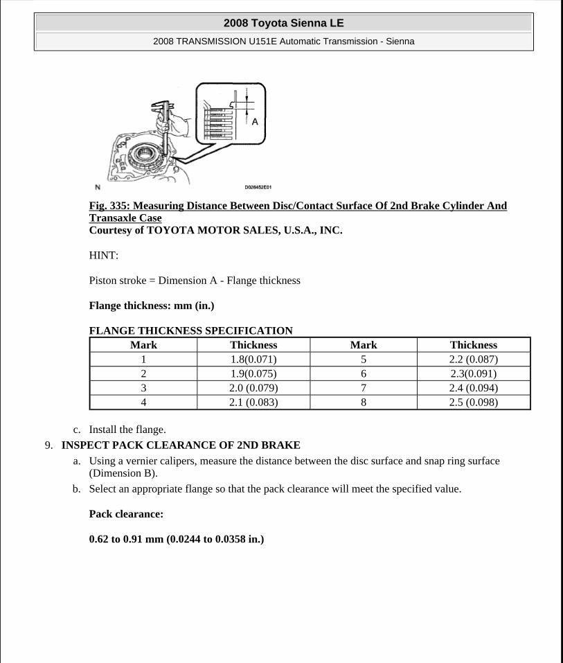
Fig. 335: Measuring Distance Between Disc/Contact Surface Of 2nd Brake Cylinder And Transaxle Case Courtesy of TOYOTA MOTOR SALES, U.S.A., INC.
HINT:
Piston stroke = Dimension A - Flange thickness
Flange thickness: mm (in.)
FLANGE THICKNESS SPECIFICATION
c. Install the flange.
9. INSPECT PACK CLEARANCE OF 2ND BRAKE
a. Using a vernier calipers, measure the distance between the disc surface and snap ring surface (Dimension B).
b. Select an appropriate flange so that the pack clearance will meet the specified value.
Pack clearance:
0.62 to 0.91 mm (0.0244 to 0.0358 in.)
Mark Thickness Mark Thickness1 1.8(0.071) 5 2.2 (0.087)2 1.9(0.075) 6 2.3(0.091)3 2.0 (0.079) 7 2.4 (0.094)4 2.1 (0.083) 8 2.5 (0.098)
2008 Toyota Sienna LE
2008 TRANSMISSION U151E Automatic Transmission - Sienna
Microsoft
Wednesday, August 12, 2009 2:03:28 PM Page 292 © 2005 Mitchell Repair Information Company, LLC.

Fig. 336: Measuring Distance Between Disc Surface And Snap Ring Surface Courtesy of TOYOTA MOTOR SALES, U.S.A., INC.
HINT:
Piston stroke = Dimension B - Flange thickness - Snap ring thickness 1.6 mm (0.063 in.)
Flange thickness: mm (in.)
FLANGE THICKNESS SPECIFICATION
10. INSPECT PACK CLEARANCE OF UNDERDRIVE BRAKE
a. Using a dial indicator, measure the underdrive brake pack clearance while applying and releasing compressed air (392 kPa, 4.0 kgf/cm2 , 57 psi).
Pack clearance:
1.81 to 2.20 mm (0.0713 to 0.0866 in.)
HINT:
Select an appropriate flange from the table below so that it will meet the specified value.
Mark Thickness Mark Thickness1 3.0(0.118) 5 3.4(0.134)2 3.1 (0.122) 6 3.5 (0.138)3 3.2(0.126) 7 3.6 (0.142)4 3.3(0.130) 8 -
2008 Toyota Sienna LE
2008 TRANSMISSION U151E Automatic Transmission - Sienna
Microsoft
Wednesday, August 12, 2009 2:03:28 PM Page 293 © 2005 Mitchell Repair Information Company, LLC.

Fig. 337: Measuring Underdrive Brake Pack Clearance Courtesy of TOYOTA MOTOR SALES, U.S.A., INC.
Flange thickness: mm (in.)
FLANGE THICKNESS SPECIFICATION
b. Temporarily remove the snap ring and attach it to the flange.
c. Reinstall the snap ring.
11. INSPECT UNDERDRIVE 1-WAY CLUTCH ASSEMBLY
a. Install the underdrive clutch assembly to the 1-way clutch.
b. Rotate the underdrive 1-way clutch assembly to check the rotating direction for the lock or free operation.
HINT:
If the result is not as specified, replace the underdrive 1-way clutch.
Fig. 338: Inspecting Underdrive 1-Way Clutch Assembly Courtesy of TOYOTA MOTOR SALES, U.S.A., INC.
12. INSPECT INPUT SHAFT END PLAY
Mark Thickness Mark Thickness1 3.0(0.118) 4 3.1 (0.122)2 3.2 (0.126) 5 3.3 (0.130)3 3.4(0.134) - -
2008 Toyota Sienna LE
2008 TRANSMISSION U151E Automatic Transmission - Sienna
Microsoft
Wednesday, August 12, 2009 2:03:28 PM Page 294 © 2005 Mitchell Repair Information Company, LLC.

a. Using a dial indicator, measure the input shaft end play.
End play:
0.262 to 1.244 mm (0.01 to 0.049 in.)
HINT:
If the result is not as specified, replace the input shaft or thrust needle roller bearing.
Fig. 339: Measuring Input Shaft End Play Courtesy of TOYOTA MOTOR SALES, U.S.A., INC.
REASSEMBLY
1. BEARING POSITION
2008 Toyota Sienna LE
2008 TRANSMISSION U151E Automatic Transmission - Sienna
Microsoft
Wednesday, August 12, 2009 2:03:28 PM Page 295 © 2005 Mitchell Repair Information Company, LLC.

Fig. 340: Exploded View Of Bearing Position Courtesy of TOYOTA MOTOR SALES, U.S.A., INC.
FRONT/REAR RACE AND THRUST BEARING DIAMETER SPECIFICATION
Mark
Front Race Diameter Inside / Outside mm
(in.)
Thrust Bearing Diameter Inside / Outside mm (in.)
Rear Race Diameter Inside / Outside mm
(in.)A - 57.2 (2.252) / 84.96
(3.3449)56.4 (2.220) / 83.0
(3.268)
2008 Toyota Sienna LE
2008 TRANSMISSION U151E Automatic Transmission - Sienna
Microsoft
Wednesday, August 12, 2009 2:03:28 PM Page 296 © 2005 Mitchell Repair Information Company, LLC.
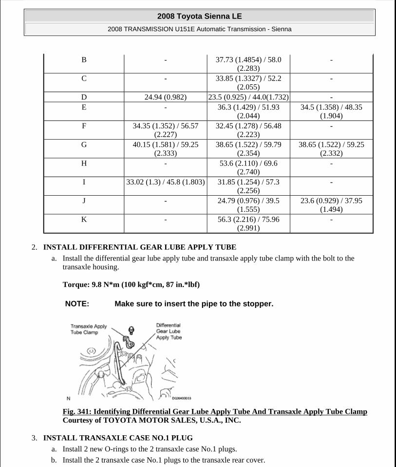
2. INSTALL DIFFERENTIAL GEAR LUBE APPLY TUBE
a. Install the differential gear lube apply tube and transaxle apply tube clamp with the bolt to the transaxle housing.
Torque: 9.8 N*m (100 kgf*cm, 87 in.*lbf)
Fig. 341: Identifying Differential Gear Lube Apply Tube And Transaxle Apply Tube Clamp Courtesy of TOYOTA MOTOR SALES, U.S.A., INC.
3. INSTALL TRANSAXLE CASE NO.1 PLUG
a. Install 2 new O-rings to the 2 transaxle case No.1 plugs.
b. Install the 2 transaxle case No.1 plugs to the transaxle rear cover.
B - 37.73 (1.4854) / 58.0 (2.283)
-
C - 33.85 (1.3327) / 52.2 (2.055)
-
D 24.94 (0.982) 23.5 (0.925) / 44.0(1.732) -E - 36.3 (1.429) / 51.93
(2.044)34.5 (1.358) / 48.35
(1.904)F 34.35 (1.352) / 56.57
(2.227)32.45 (1.278) / 56.48
(2.223)-
G 40.15 (1.581) / 59.25 (2.333)
38.65 (1.522) / 59.79 (2.354)
38.65 (1.522) / 59.25 (2.332)
H - 53.6 (2.110) / 69.6 (2.740)
-
I 33.02 (1.3) / 45.8 (1.803) 31.85 (1.254) / 57.3 (2.256)
-
J - 24.79 (0.976) / 39.5 (1.555)
23.6 (0.929) / 37.95 (1.494)
K - 56.3 (2.216) / 75.96 (2.991)
-
NOTE: Make sure to insert the pipe to the stopper.
2008 Toyota Sienna LE
2008 TRANSMISSION U151E Automatic Transmission - Sienna
Microsoft
Wednesday, August 12, 2009 2:03:28 PM Page 297 © 2005 Mitchell Repair Information Company, LLC.
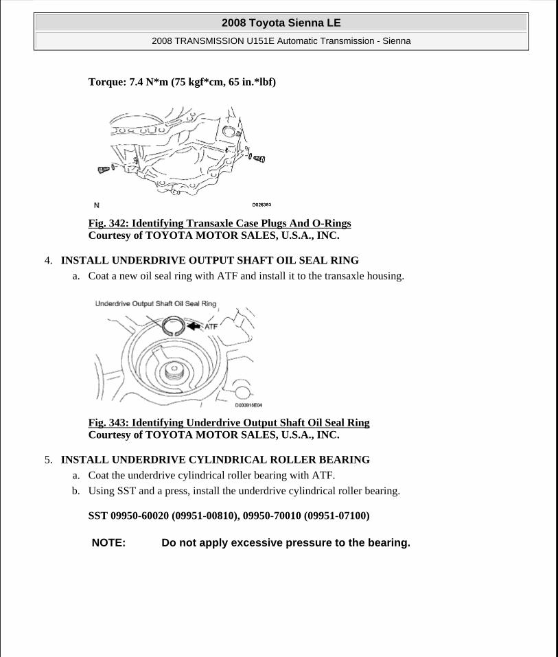
Torque: 7.4 N*m (75 kgf*cm, 65 in.*lbf)
Fig. 342: Identifying Transaxle Case Plugs And O-Rings Courtesy of TOYOTA MOTOR SALES, U.S.A., INC.
4. INSTALL UNDERDRIVE OUTPUT SHAFT OIL SEAL RING
a. Coat a new oil seal ring with ATF and install it to the transaxle housing.
Fig. 343: Identifying Underdrive Output Shaft Oil Seal Ring Courtesy of TOYOTA MOTOR SALES, U.S.A., INC.
5. INSTALL UNDERDRIVE CYLINDRICAL ROLLER BEARING
a. Coat the underdrive cylindrical roller bearing with ATF.
b. Using SST and a press, install the underdrive cylindrical roller bearing.
SST 09950-60020 (09951-00810), 09950-70010 (09951-07100)
NOTE: Do not apply excessive pressure to the bearing.
2008 Toyota Sienna LE
2008 TRANSMISSION U151E Automatic Transmission - Sienna
Microsoft
Wednesday, August 12, 2009 2:03:28 PM Page 298 © 2005 Mitchell Repair Information Company, LLC.

Fig. 344: Identifying Underdrive Cylindrical Roller Bearing Courtesy of TOYOTA MOTOR SALES, U.S.A., INC.
6. INSTALL UNDERDRIVE CLUTCH DRUM OIL SEAL RING
a. Coat 2 new oil seal rings with ATF, and install them to the transaxle rear cover.
7. INSTALL NEEDLE ROLLER BEARING
a. Wrap vinyl tape around the SST 4.0 mm (0.157 in.) from the bottom of the SST until the thickness of the tape is about 5.0 mm (0.197 in.).
SST 09950-60010 (09951-00320), 09950-70010 (09951-07100)
b. Coat the needle roller bearing with ATF.
NOTE: Do not expand the end gap of the oil seal ring too much.
Fix the hooks firmly. Confirm that the oil seal ring rotates freely in its groove.
Fig. 345: Identifying Underdrive Clutch Drum Oil Seal Ring Courtesy of TOYOTA MOTOR SALES, U.S.A., INC.
NOTE: Clean SST to remove deposited oil, before wrapping vinyl tape.
2008 Toyota Sienna LE
2008 TRANSMISSION U151E Automatic Transmission - Sienna
Microsoft
Wednesday, August 12, 2009 2:03:28 PM Page 299 © 2005 Mitchell Repair Information Company, LLC.

Fig. 346: Wrapping Vinyl Tape Around SST Courtesy of TOYOTA MOTOR SALES, U.S.A., INC.
c. Using SST and a press, install the needle-roller bearing to the transaxle case.
SST 09950-60010 (09951-00320), 09950-70010 (09951-07100)
Fig. 347: Pressing Needle-Roller Bearing To Transaxle Case Courtesy of TOYOTA MOTOR SALES, U.S.A., INC.
8. INSTALL UNDERDRIVE BRAKE PISTON
a. Coat 2 new O-rings with ATF, and install them to the underdrive brake piston.
NOTE: When the wrapped vinyl tape contacts the transaxle case, stop press-fitting.
NOTE: Make sure that the O-rings are not twisted or pinched when they are installed.
Apply sufficient ATF to the O-ring before installing.
2008 Toyota Sienna LE
2008 TRANSMISSION U151E Automatic Transmission - Sienna
Microsoft
Wednesday, August 12, 2009 2:03:29 PM Page 300 © 2005 Mitchell Repair Information Company, LLC.

b. Coat the underdrive brake piston with ATF.
c. Install the underdrive brake piston to the transaxle case.
Fig. 349: Identifying Underdrive Brake Piston Courtesy of TOYOTA MOTOR SALES, U.S.A., INC.
9. INSTALL UNDERDRIVE BRAKE RETURN SPRING SUB-ASSEMBLY
a. Place SST on the return spring and compress the return spring with a press.
SST 09387-00020
b. Using a snap ring expander, install the snap ring to the transaxle case.
Fig. 348: Locating Underdrive Brake Piston O-Rings Courtesy of TOYOTA MOTOR SALES, U.S.A., INC.
NOTE: Be careful not to damage the O-ring.
2008 Toyota Sienna LE
2008 TRANSMISSION U151E Automatic Transmission - Sienna
Microsoft
Wednesday, August 12, 2009 2:03:29 PM Page 301 © 2005 Mitchell Repair Information Company, LLC.

Fig. 350: Compressing Return Spring With SST To Access Snap Ring Courtesy of TOYOTA MOTOR SALES, U.S.A., INC.
10. INSTALL BREATHER PLUG NO.2 (ATM)
11. INSTALL COUNTER DRIVE GEAR BEARING
a. Coat the counterdrive gear bearing with ATF.
b. Using SST and a press, install the bearing outer race.
SST 09950-60020 (09951-01030), 09950-70010 (09951-07150), 09649-17010
c. Using a snap ring expander, install the snap ring.
NOTE: Stop the press when the spring seat is lowered 1 to 2 mm (0.039 to 0.078 in.) from the snap ring groove, to prevent the spring seat from being deformed.
Do not expand the snap ring excessively.
Installing the spring sub-assembly, check that all of the springs are fit in the piston correctly.
The snap ring should be fully engaged in the groove of the transaxle case.
NOTE: Do not apply excessive pressure to the bearing.
Press-fit the bearing outer race until it contacts the transaxle case.
Fig. 351: Using SST And Press To Install Bearing Outer Race Courtesy of TOYOTA MOTOR SALES, U.S.A., INC.
NOTE: The white mark side of the snap ring should face upward.
2008 Toyota Sienna LE
2008 TRANSMISSION U151E Automatic Transmission - Sienna
Microsoft
Wednesday, August 12, 2009 2:03:29 PM Page 302 © 2005 Mitchell Repair Information Company, LLC.

Fig. 352: Identifying Snap Ring Courtesy of TOYOTA MOTOR SALES, U.S.A., INC.
12. INSTALL COUNTER DRIVE GEAR
a. Coat the counterdrive gear with ATF.
b. Using SST and a press, install the tapered roller bearing to the counter drive gear.
SST 09950-70010 (09951-07150), 09649-17010
Fig. 353: Using SST And Press To Install Tapered Roller Bearing To Counter Drive Gear Courtesy of TOYOTA MOTOR SALES, U.S.A., INC.
c. Using SST and a press, install the counter drive gear and bearing to the transaxle case.
SST 09950-70010 (09951-07150), 09223-15030, 09527-17011, 09950-60020 (09951-00750)
NOTE: Do not apply excessive pressure to the bearing.
NOTE: Do not apply excessive pressure to the counter drive gear.
2008 Toyota Sienna LE
2008 TRANSMISSION U151E Automatic Transmission - Sienna
Microsoft
Wednesday, August 12, 2009 2:03:29 PM Page 303 © 2005 Mitchell Repair Information Company, LLC.

Fig. 354: Pressing Counter Drive Gear And Bearing To Transaxle Case Courtesy of TOYOTA MOTOR SALES, U.S.A., INC.
13. INSTALL 1ST AND REVERSE BRAKE PISTON
a. Coat 2 new O-rings with ATF.
b. Install the 2 O-rings to the 1st and reverse brake piston.
c. Coat the 1st and reverse brake piston with ATF, and install it to the transaxle case.
NOTE: Make sure that the O-rings are not twisted or pinched when they are installed.
Apply sufficient ATF to the O-ring prior to assembling.
Fig. 355: Locating 1st And Reverse Brake Piston O-Rings Courtesy of TOYOTA MOTOR SALES, U.S.A., INC.
2008 Toyota Sienna LE
2008 TRANSMISSION U151E Automatic Transmission - Sienna
Microsoft
Wednesday, August 12, 2009 2:03:29 PM Page 304 © 2005 Mitchell Repair Information Company, LLC.

Fig. 356: Identifying 1st And Reverse Brake Piston Courtesy of TOYOTA MOTOR SALES, U.S.A., INC.
14. INSTALL 1ST AND REVERSE BRAKE RETURN SPRING SUB-ASSEMBLY
a. Place SST on the return spring and compress the return spring with a press.
SST 09387-00070
b. Using a snap ring expander, install the snap ring to the transaxle case.
Fig. 357: Compressing Return Spring Using SST Courtesy of TOYOTA MOTOR SALES, U.S.A., INC.
NOTE: Be careful not to damage the O-ring.
NOTE: Stop the press when the spring seat is lowered to the place 1 to 2 mm (0.039 to 0.078 in.) from the snap ring groove, preventing the spring seat from being deformed.
Do not expand the snap ring excessively.
Installing the spring sub-assembly, check that all of the springs are fit in the piston correctly.
The snap ring should be fully engaged in the groove of the cylinder.
Fix the snap ring to the inside of the claw of the spring seat firmly.
2008 Toyota Sienna LE
2008 TRANSMISSION U151E Automatic Transmission - Sienna
Microsoft
Wednesday, August 12, 2009 2:03:29 PM Page 305 © 2005 Mitchell Repair Information Company, LLC.

15. INSTALL FRONT PLANETARY RING GEAR
a. Using a screwdriver, install the front planetary ring gear and snap ring to the brake hub.
Fig. 358: Identifying Snap Ring, Brake Hub And Front Planetary Ring Gear Courtesy of TOYOTA MOTOR SALES, U.S.A., INC.
16. INSTALL FRONT PLANETARY GEAR ASSEMBLY
a. Install the front planetary gear assembly to the brake hub.
Fig. 359: View Of Front Planetary Gear Assembly And Brake Hub Courtesy of TOYOTA MOTOR SALES, U.S.A., INC.
b. Using SST and a press, press-fit the front planetary gear assembly.
SST 09950-60010 (09951-00500), 09950-70010 (09951-07100)
NOTE: Confirm that the snap ring is engaged in the groove of the brake hub correctly.
NOTE: Do not apply excessive pressure to the planetary gear assembly.
Press the inner race of LH tapered roller bearing, counter gear and front planetary gear assembly to the position where no preload should be applied to one pair of tapered roller bearings (left and right).
2008 Toyota Sienna LE
2008 TRANSMISSION U151E Automatic Transmission - Sienna
Microsoft
Wednesday, August 12, 2009 2:03:29 PM Page 306 © 2005 Mitchell Repair Information Company, LLC.

c. Install a new washer as shown in the illustration.
Fig. 361: Identifying Washer Courtesy of TOYOTA MOTOR SALES, U.S.A., INC.
d. Using SST, install the nut.
SST 09387-00030, 09387-00080
Torque: 280 N*m (3,355 kgf*cm, 207 ft.*lbf)
Fig. 360: Using SST And Press To Press-Fit Front Planetary Gear Assembly Courtesy of TOYOTA MOTOR SALES, U.S.A., INC.
NOTE: Assemble the washer after pressing each part, then tighten the nut to the minimum tightening torque.
2008 Toyota Sienna LE
2008 TRANSMISSION U151E Automatic Transmission - Sienna
Microsoft
Wednesday, August 12, 2009 2:03:29 PM Page 307 © 2005 Mitchell Repair Information Company, LLC.

Fig. 362: Removing/Installing Front Planetary Gear Nut With SST Courtesy of TOYOTA MOTOR SALES, U.S.A., INC.
e. Using SST and a torque wrench, measure the turning torque of the bearing while rotating SST at 60 rpm. When the measured value is not as specified, gradually tighten the nut until it reaches the specified value.
Fig. 363: Measuring Turning Torque Of Bearing Courtesy of TOYOTA MOTOR SALES, U.S.A., INC.
SST 09387-00080
Standard: Turning torque at 60 rpm
Bearing: New Bearing: 0.51 to 1.02 N*m (5.1 to 10.0 kgf*cm, 4.4 to 8.7 in.*lbf)
Used Bearing: 0.26 to 0.51 N*m (2.7 to 5.2 kgf*cm, 2.3 to 4.5 in.*lbf)
HINT:
Use a torque wrench with a fulcrum length of 160 mm (6.3 in.).
f. Tighten the nut gradually until the specified turning torque of tapered roller bearing is measured.
Torque: 350 N*m (3,569 kgf*cm, 258 ft.*lbf)
g. Using a chisel and hammer, stake the front lock washer.
2008 Toyota Sienna LE
2008 TRANSMISSION U151E Automatic Transmission - Sienna
Microsoft
Wednesday, August 12, 2009 2:03:29 PM Page 308 © 2005 Mitchell Repair Information Company, LLC.

Fig. 364: Using Chisel And Hammer To Stake Front Lock Washer Courtesy of TOYOTA MOTOR SALES, U.S.A., INC.
17. INSTALL INPUT SUN GEAR
a. Coat the 2 thrust bearings with ATF.
b. Install the 2 thrust bearings, the bearing race and the input sun gear to the front planetary gear assembly.
Fig. 365: Identifying Thrust Bearings, Bearing Race And Input Sun Gear Courtesy of TOYOTA MOTOR SALES, U.S.A., INC.
Thrust bearing and bearing race diameter: mm (in.)
THRUST BEARING AND BEARING RACE DIAMETER SPECIFICATION
NOTE: Install the bearing race on the side of the front planetary carrier. Be careful about the direction of the race.
Installing thrust bearing and front sun gears, be careful about the direction of the parts.
Install the bearing race on the side of the front sun gear. Be careful about the direction of the race.
Install the thrust bearing and the race after holding the parts on the input sun gear by applying grease. Make sure that the assembling order is correct.
Inside Outside
2008 Toyota Sienna LE
2008 TRANSMISSION U151E Automatic Transmission - Sienna
Microsoft
Wednesday, August 12, 2009 2:03:29 PM Page 309 © 2005 Mitchell Repair Information Company, LLC.

18. INSTALL REAR PLANETARY GEAR ASSEMBLY
a. Install the rear planetary gear assembly to the rear planetary ring gear.
Fig. 366: Identifying Rear Planetary Gear Assembly Courtesy of TOYOTA MOTOR SALES, U.S.A., INC.
b. Using a screwdriver, install the snap ring.
Fig. 367: Identifying Snap Ring Courtesy of TOYOTA MOTOR SALES, U.S.A., INC.
19. INSTALL 1ST AND REVERSE BRAKE CLUTCH DISC
a. Coat the 6 discs with ATF.
b. Install the 7 plates and 6 discs.
Thrust Bearing, A 32.5 (1.28) 56.5 (2.224)Bearing Race, B 40.2 (1.583) 59.3 (2.335)
Thrust Bearing, C 38.6 (1.520) 59.7 (2.35)Bearing Race, D 38.6 (1.520) 59.3 (2.335)
NOTE: Confirm that the snap ring is fixed in the groove of the 1st and reverse brake hub correctly.
NOTE: Make sure that the plates, discs, and flange are installed as shown in the illustration.
2008 Toyota Sienna LE
2008 TRANSMISSION U151E Automatic Transmission - Sienna
Microsoft
Wednesday, August 12, 2009 2:03:29 PM Page 310 © 2005 Mitchell Repair Information Company, LLC.

Fig. 368: Identifying Discs And Plates Courtesy of TOYOTA MOTOR SALES, U.S.A., INC.
20. INSPECT PACK CLEARANCE OF FIRST AND REVERSE BRAKE
a. Using vernier calipers, measure the distance between the disc surface and the contact surface of the 2nd brake cylinder and transaxle case (Dimension A).
b. Select an appropriate flange so that the pack clearance will meet the specified value.
Pack clearance: 1.16 to 1.35 mm (0.0457 to 0.0531 in.)
Fig. 369: Measuring Distance Between Disc/Contact Surface Of 2nd Brake Cylinder And Transaxle Case Courtesy of TOYOTA MOTOR SALES, U.S.A., INC.
HINT:
Piston stroke = Dimension A - Flange thickness
Flange thickness: mm (in.)
FLANGE THICKNESS SPECIFICATION Mark Thickness Mark Thickness
1 1.8 (0.071) 5 2.2 (0.087)2 1.9 (0.075) 6 2.3 (0.091)3 2.0 (0.079) 7 2.4 (0.094)4 2.1 (0.083) 8 2.5 (0.098)
2008 Toyota Sienna LE
2008 TRANSMISSION U151E Automatic Transmission - Sienna
Microsoft
Wednesday, August 12, 2009 2:03:29 PM Page 311 © 2005 Mitchell Repair Information Company, LLC.

c. Install the flange.
Fig. 370: Identifying Flange Courtesy of TOYOTA MOTOR SALES, U.S.A., INC.
21. INSTALL SECOND BRAKE PISTON ASSEMBLY
a. Install the second brake piston assembly to the transaxle case.
Fig. 371: Identifying Second Brake Piston Assembly Courtesy of TOYOTA MOTOR SALES, U.S.A., INC.
b. Install the snap ring and measure the inside diameter.
Inside diameter: Greater than 167 mm (6.57 in.)
NOTE: Make sure that the taper snap ring is installed in the correct direction.
When the diameter does not meet the specified value, replace the snap ring with a new one.
After installing, confirm that there is no clearance between the 2nd brake cylinder and the fitting surface of the cylinder in the transaxle case.
2008 Toyota Sienna LE
2008 TRANSMISSION U151E Automatic Transmission - Sienna
Microsoft
Wednesday, August 12, 2009 2:03:29 PM Page 312 © 2005 Mitchell Repair Information Company, LLC.

22. INSTALL 1-WAY CLUTCH SLEEVE OUTER
a. Install the 1-way clutch sleeve outer to the 2nd brake cylinder assembly.
Fig. 373: Identifying 1-Way Clutch Sleeve Outer Courtesy of TOYOTA MOTOR SALES, U.S.A., INC.
23. INSTALL 1-WAY CLUTCH ASSEMBLY
a. Install the 1-way clutch inner race to the 1-way clutch.
Fig. 372: Identifying Snap Ring Courtesy of TOYOTA MOTOR SALES, U.S.A., INC.
NOTE: Make sure that the outer sleeve is installed in the correct direction.
NOTE: Make sure that the inner race is installed in the correct direction.
Confirm that the discrimination mark is visible.
2008 Toyota Sienna LE
2008 TRANSMISSION U151E Automatic Transmission - Sienna
Microsoft
Wednesday, August 12, 2009 2:03:29 PM Page 313 © 2005 Mitchell Repair Information Company, LLC.

b. Check the rotating direction of 1-way clutch for the lock or free operation as shown in the illustration.
Fig. 375: Checking Rotating Direction Of 1-Way Clutch Courtesy of TOYOTA MOTOR SALES, U.S.A., INC.
c. Install the 1-way clutch and thrust needle roller bearing to the 1-way clutch sleeve outer.
Bearing diameter: mm (in.)
BEARING DIAMETER SPECIFICATION
Fig. 374: Identifying 1-Way Clutch Inner Race Courtesy of TOYOTA MOTOR SALES, U.S.A., INC.
Inside OutsideBearing 53.6 (2.110) 69.4 (2.732)
NOTE: Install the thrust bearing properly so that no-colored race will be visible.
2008 Toyota Sienna LE
2008 TRANSMISSION U151E Automatic Transmission - Sienna
Microsoft
Wednesday, August 12, 2009 2:03:29 PM Page 314 © 2005 Mitchell Repair Information Company, LLC.

Fig. 376: Identifying Thrust Needle Roller Bearing And 1-Way Clutch Assembly Courtesy of TOYOTA MOTOR SALES, U.S.A., INC.
24. INSTALL PLANETARY CARRIER THRUST WASHER NO.1
a. Coat the planetary carrier thrust washer No.1 with yellow petrolatum, and install the washer onto the planetary sun gear assembly.
Fig. 377: Identifying Planetary Carrier Thrust Washer Courtesy of TOYOTA MOTOR SALES, U.S.A., INC.
25. REMOVE REAR PLANETARY SUN GEAR ASSEMBLY
a. Coat the planetary carrier thrust washer No.2 with yellow petrolatum, and install the washer onto the rear planetary sun gear.
NOTE: After installing, confirm that the projection should be fixed firmly in the hole of the planetary sun gear assembly.
2008 Toyota Sienna LE
2008 TRANSMISSION U151E Automatic Transmission - Sienna
Microsoft
Wednesday, August 12, 2009 2:03:29 PM Page 315 © 2005 Mitchell Repair Information Company, LLC.

Fig. 378: Identifying Planetary Carrier Thrust Washer And Rear Planetary Sun Gear Assembly Courtesy of TOYOTA MOTOR SALES, U.S.A., INC.
b. Coat the bearing with yellow petrolatum, and install the bearing onto the rear planetary sun gear.
Bearing diameter: mm (in.)
BEARING DIAMETER SPECIFICATION
Fig. 379: Identifying Bearing And Bearing Race Courtesy of TOYOTA MOTOR SALES, U.S.A., INC.
c. Install the rear planetary sun gear assembly to the rear planetary gear.
Inside OutsideRace, A 33.0 (1.299) 45.4 (1.787)
Bearing, B 31.85 (1.254) 45.2 (1.78)
NOTE: Installing the rear planetary sun gear assembly, make sure that the B1 discs are engaged.
2008 Toyota Sienna LE
2008 TRANSMISSION U151E Automatic Transmission - Sienna
Microsoft
Wednesday, August 12, 2009 2:03:29 PM Page 316 © 2005 Mitchell Repair Information Company, LLC.

Fig. 380: Identifying Rear Planetary Sun Gear Assembly Courtesy of TOYOTA MOTOR SALES, U.S.A., INC.
26. INSTALL 2ND BRAKE CLUTCH DISC
a. Coat the 4 discs with ATF.
b. Install the 4 discs and 5 plates to the transaxle case.
c. Temporarily install the snap ring.
Fig. 381: Identifying Discs And Plates Courtesy of TOYOTA MOTOR SALES, U.S.A., INC.
27. INSPECT PACK CLEARANCE OF 2ND BRAKE
a. Using a vernier calipers, measure the distance between the disc surface and snap ring surface (Dimension B).
b. Select an appropriate flange so that the pack clearance will meet the specified value.
Clearance: 0.62 to 0.91 mm (0.0244 to 0.0358 in.)
HINT:
Piston stroke = Dimension B - Flange thickness - Snap ring thickness 1.6 mm (0.063 in.)
2008 Toyota Sienna LE
2008 TRANSMISSION U151E Automatic Transmission - Sienna
Microsoft
Wednesday, August 12, 2009 2:03:29 PM Page 317 © 2005 Mitchell Repair Information Company, LLC.

Fig. 382: Measuring Distance Between Disc Surface And Snap Ring Surface Courtesy of TOYOTA MOTOR SALES, U.S.A., INC.
Flange thickness: mm (in.)
FLANGE THICKNESS SPECIFICATION
c. Temporarily remove the snap ring, attach the selected flange and reinstall the snap ring.
Fig. 383: Identifying Snap Ring Courtesy of TOYOTA MOTOR SALES, U.S.A., INC.
28. INSTALL OVERDRIVE DIRECT CLUTCH HUB SUB-ASSEMBLY
a. Install the direct clutch hub to the planetary gear assembly.
Mark Thickness Mark Thickness1 3.0 (0.118) 5 3.4 (0.134)2 3.1 (0.122) 6 3.5 (0.138)3 3.2 (0.126) 7 3.6 (0.142)4 3.3 (0.130) 8 -
NOTE: Secure the snap ring so that the ends visible through the groove of the transaxle case.
NOTE: Be careful not to damage the bushing inside the overdrive clutch hub during installation.
2008 Toyota Sienna LE
2008 TRANSMISSION U151E Automatic Transmission - Sienna
Microsoft
Wednesday, August 12, 2009 2:03:29 PM Page 318 © 2005 Mitchell Repair Information Company, LLC.

b. Coat the thrust bearing with ATF.
c. Install the bearing race and the thrust bearing to the direct clutch hub.
Fig. 384: Identifying Overdrive Direct Clutch Hub And Planetary Gear Assembly Courtesy of TOYOTA MOTOR SALES, U.S.A., INC.
Bearing and race diameter: mm (in.)
BEARING AND RACE DIAMETER SPECIFICATION
29. INSTALL DIRECT CLUTCH ASSEMBLY
a. Coat the thrust bearing with ATF.
b. Install the direct clutch assembly and thrust bearing to the rear planetary sun gear assembly.
Fig. 385: Identifying Thrust Bearing And Direct Clutch Assembly Courtesy of TOYOTA MOTOR SALES, U.S.A., INC.
NOTE: Be careful not to drop the bearing when it is installed.
Inside OutsideBearing, A 24.7 (0.972) 39.5 (1.555)
Race, B 23.6 (0.929) 38.0 (1.496)
NOTE: The disc in the direct clutch should completely match with the hub attached outside the rear planetary sun gear. Otherwise, the rear
2008 Toyota Sienna LE
2008 TRANSMISSION U151E Automatic Transmission - Sienna
Microsoft
Wednesday, August 12, 2009 2:03:29 PM Page 319 © 2005 Mitchell Repair Information Company, LLC.
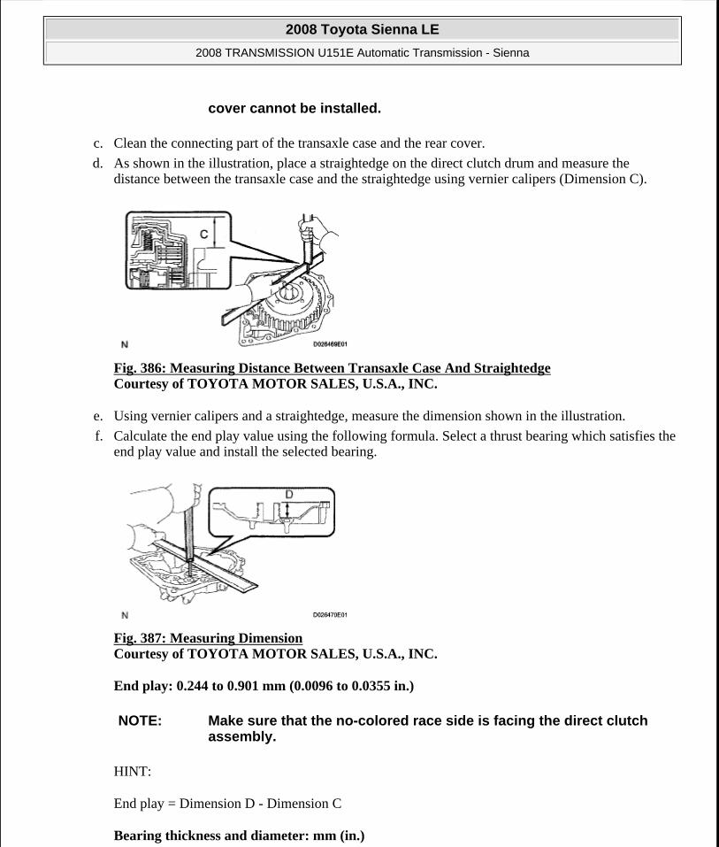
c. Clean the connecting part of the transaxle case and the rear cover.
d. As shown in the illustration, place a straightedge on the direct clutch drum and measure the distance between the transaxle case and the straightedge using vernier calipers (Dimension C).
Fig. 386: Measuring Distance Between Transaxle Case And Straightedge Courtesy of TOYOTA MOTOR SALES, U.S.A., INC.
e. Using vernier calipers and a straightedge, measure the dimension shown in the illustration.
f. Calculate the end play value using the following formula. Select a thrust bearing which satisfies the end play value and install the selected bearing.
Fig. 387: Measuring Dimension Courtesy of TOYOTA MOTOR SALES, U.S.A., INC.
End play: 0.244 to 0.901 mm (0.0096 to 0.0355 in.)
HINT:
End play = Dimension D - Dimension C
Bearing thickness and diameter: mm (in.)
cover cannot be installed.
NOTE: Make sure that the no-colored race side is facing the direct clutch assembly.
2008 Toyota Sienna LE
2008 TRANSMISSION U151E Automatic Transmission - Sienna
Microsoft
Wednesday, August 12, 2009 2:03:29 PM Page 320 © 2005 Mitchell Repair Information Company, LLC.

BEARING THICKNESS AND DIAMETER SPECIFICATION
30. INSTALL GOVERNOR APPLY GASKET NO.1
a. Install 3 new governor apply gaskets No.1 to the transaxle case.
Fig. 388: Locating Governor Apply Gaskets Courtesy of TOYOTA MOTOR SALES, U.S.A., INC.
31. INSTALL BRAKE APPLY TUBE
a. Install the clamp to the brake apply tube.
b. Install the clutch apply tube.
Fig. 389: Identifying Brake Apply Tube Courtesy of TOYOTA MOTOR SALES, U.S.A., INC.
c. Install the brake apply tube and a bolt to the transaxle case.
Torque: 5.4 N*m (55 kgf*cm, 48 in.*lbf)
Thickness Inside Outside3.6 (0.1417) 56.3 (2.217) 75.7 (2.980)3.8 (0.1496) 56.3 (2.217) 75.7 (2.980)
NOTE: Make sure to install the clamp to the apply tube before installing the apply tube to the transaxle case. This prevents the apply tube from being deformed or damaged.
2008 Toyota Sienna LE
2008 TRANSMISSION U151E Automatic Transmission - Sienna
Microsoft
Wednesday, August 12, 2009 2:03:29 PM Page 321 © 2005 Mitchell Repair Information Company, LLC.

Fig. 390: Identifying Brake Apply Tube And Clutch Apply Tube Courtesy of TOYOTA MOTOR SALES, U.S.A., INC.
32. INSTALL NEEDLE ROLLER BEARING
a. Using SST and a press, press the needle roller bearing into the transaxle rear cover.
SST 09950-60010 (09951-00230, 09952-06010)
Press fit depth: 20.55 to 21.25 mm (0.8091 to 0.8366 in.)
Fig. 391: Using SST And Press To Install Needle Roller Bearing To Transaxle Rear Cover Courtesy of TOYOTA MOTOR SALES, U.S.A., INC.
b. Coat a needle roller bearing with ATF.
33. INSTALL REAR CLUTCH OIL SEAL RING OUTER
a. Coat 3 new rear clutch oil seal rings with ATF, install them to the transaxle rear cover.
NOTE: The tube should be securely inserted until it reaches the stopper.
NOTE: The engraved mark side of the bearing should face upward.
Repeat the press fit until the specified value is obtained.
NOTE: The snap ring should be fully engaged in the groove of the drum.
2008 Toyota Sienna LE
2008 TRANSMISSION U151E Automatic Transmission - Sienna
Microsoft
Wednesday, August 12, 2009 2:03:29 PM Page 322 © 2005 Mitchell Repair Information Company, LLC.
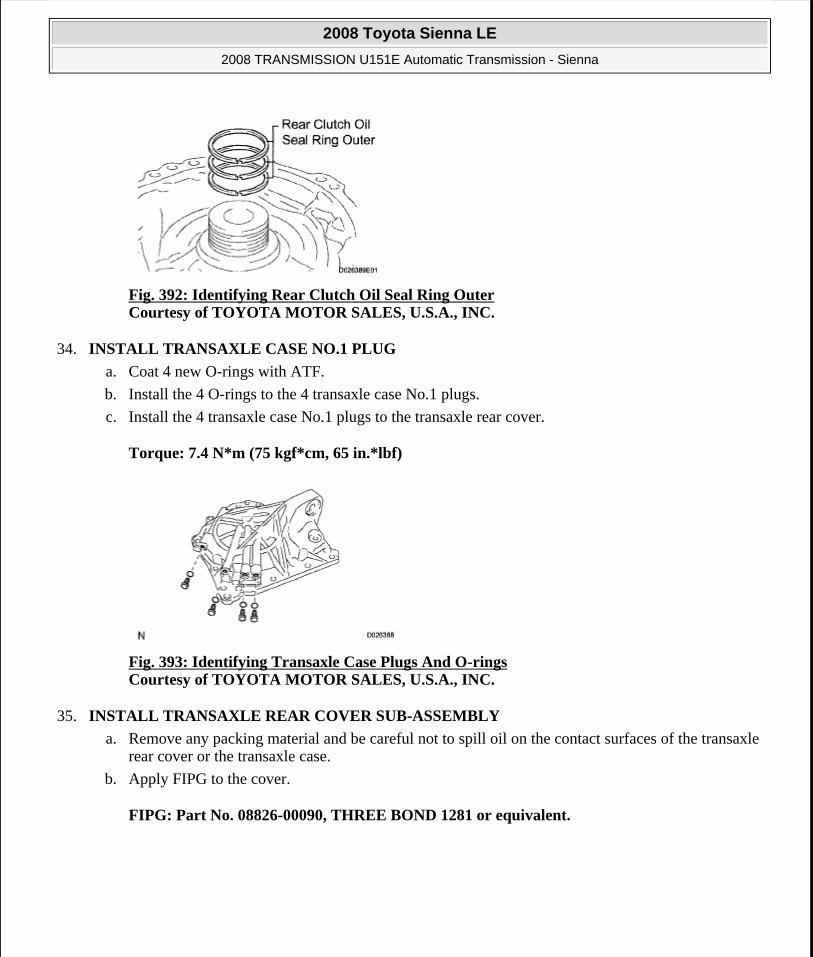
Fig. 392: Identifying Rear Clutch Oil Seal Ring Outer Courtesy of TOYOTA MOTOR SALES, U.S.A., INC.
34. INSTALL TRANSAXLE CASE NO.1 PLUG
a. Coat 4 new O-rings with ATF.
b. Install the 4 O-rings to the 4 transaxle case No.1 plugs.
c. Install the 4 transaxle case No.1 plugs to the transaxle rear cover.
Torque: 7.4 N*m (75 kgf*cm, 65 in.*lbf)
Fig. 393: Identifying Transaxle Case Plugs And O-rings Courtesy of TOYOTA MOTOR SALES, U.S.A., INC.
35. INSTALL TRANSAXLE REAR COVER SUB-ASSEMBLY
a. Remove any packing material and be careful not to spill oil on the contact surfaces of the transaxle rear cover or the transaxle case.
b. Apply FIPG to the cover.
FIPG: Part No. 08826-00090, THREE BOND 1281 or equivalent.
2008 Toyota Sienna LE
2008 TRANSMISSION U151E Automatic Transmission - Sienna
Microsoft
Wednesday, August 12, 2009 2:03:29 PM Page 323 © 2005 Mitchell Repair Information Company, LLC.

Fig. 394: Identifying FIPG Applying Area On Transaxle Rear Cover Courtesy of TOYOTA MOTOR SALES, U.S.A., INC.
c. Apply liquid sealer to the "A" bolt threads.
Sealant: Part No. 08833-00080, THREE BOND 1344, LOCTITE 242 or equivalent.
d. Install the 11 bolts.
Torque: Bolt A 19 N*m (190 kgf*cm, 14 ft.*lbf)
Other bolts: 25 N*m (250 kgf*cm, 18 ft.*lbf)
Fig. 395: Locating Transaxle Rear Cover Bolts Courtesy of TOYOTA MOTOR SALES, U.S.A., INC.
36. INSTALL UNDERDRIVE CLUTCH DISC NO.2
a. Coat the 4 discs with ATF.
b. Install the 4 discs, 4 plates and flange to the transaxle case.
NOTE: Make sure that the FIPG is applied in a bead (section diameter: ø1.2) so that the entire sealing surface will be evenly sealed. The FIPG should also protrude slightly from the flange after the assembly of the parts has been completed.
NOTE: Be careful about the order of discs, plate and flange assembly.
2008 Toyota Sienna LE
2008 TRANSMISSION U151E Automatic Transmission - Sienna
Microsoft
Wednesday, August 12, 2009 2:03:29 PM Page 324 © 2005 Mitchell Repair Information Company, LLC.

Fig. 396: Identifying Discs, Plates And Flange Courtesy of TOYOTA MOTOR SALES, U.S.A., INC.
c. Using a screwdriver, install the snap ring.
Fig. 397: Locating Snap Ring Courtesy of TOYOTA MOTOR SALES, U.S.A., INC.
37. INSPECT PACK CLEARANCE OF UNDERDRIVE BRAKE
a. Using a dial indicator, measure the underdrive brake pack clearance while applying and releasing compressed air (392 kPa, 4.0 kgf/cm2 , 57 psi).
Fig. 398: Measuring Underdrive Brake Pack Clearance Courtesy of TOYOTA MOTOR SALES, U.S.A., INC.
NOTE: The snap ring should be fully engaged in the groove of the drum.
2008 Toyota Sienna LE
2008 TRANSMISSION U151E Automatic Transmission - Sienna
Microsoft
Wednesday, August 12, 2009 2:03:29 PM Page 325 © 2005 Mitchell Repair Information Company, LLC.

Pack clearance: 1.81 to 2.20 mm (0.0713 to 0.0866 in.)
HINT:
Select an appropriate flange from the table below so that it will meet the specified value.
Flange thickness: mm (in.)
FLANGE THICKNESS SPECIFICATION
b. Temporarily remove the snap ring and attach it to the flange.
c. Reinstall the snap ring.
38. INSPECT UNDERDRIVE 1-WAY CLUTCH ASSEMBLY
a. Install the underdrive clutch assembly to the 1-way clutch.
b. Rotate the underdrive clutch assembly to check the rotating direction for the lock or free operation.
Fig. 399: Inspecting Underdrive 1-Way Clutch Assembly Courtesy of TOYOTA MOTOR SALES, U.S.A., INC.
39. INSTALL UNDERDRIVE 1-WAY CLUTCH ASSEMBLY
a. Install the outer race retainer to the 1-way clutch.
Mark Thickness Mark Thickness1 3.0 (0.118) 4 3.1 (0.122)2 3.2 (0.126) 5 3.3 (0.130)3 3.4 (0.134) - -
NOTE: Fix the outer race retainer to the external tooth of the 1-way clutch firmly.
2008 Toyota Sienna LE
2008 TRANSMISSION U151E Automatic Transmission - Sienna
Microsoft
Wednesday, August 12, 2009 2:03:29 PM Page 326 © 2005 Mitchell Repair Information Company, LLC.

Fig. 400: Identifying Outer Race Retainer Courtesy of TOYOTA MOTOR SALES, U.S.A., INC.
b. Install the 1-way clutch to the transaxle case.
Fig. 401: Identifying Mark On 1-Way Clutch Outer Race Courtesy of TOYOTA MOTOR SALES, U.S.A., INC.
c. Using a screwdriver, install the snap ring to the transaxle case.
Fig. 402: Locating Snap Ring Courtesy of TOYOTA MOTOR SALES, U.S.A., INC.
NOTE: Make sure that the mark on the 1-way clutch outer race is visible.
NOTE: The snap ring should be fixed fully engaged in the groove of the transaxle case.
2008 Toyota Sienna LE
2008 TRANSMISSION U151E Automatic Transmission - Sienna
Microsoft
Wednesday, August 12, 2009 2:03:29 PM Page 327 © 2005 Mitchell Repair Information Company, LLC.

40. INSTALL UNDERDRIVE CLUTCH ASSEMBLY
a. Coat the bearing and bearing race with petroleum jelly, install them onto the underdrive clutch.
Bearing and bearing race diameter: mm (in.)
BEARING AND BEARING RACE DIAMETER SPECIFICATION
Fig. 403: Identifying Underdrive Clutch Assembly Courtesy of TOYOTA MOTOR SALES, U.S.A., INC.
b. Install the underdrive clutch assembly to the transaxle case.
41. INSTALL PARKING LOCK PAWL
a. Install the pawl pin and spring to the parking lock pawl.
Fig. 404: Identifying Pawl Pin, Spring And Parking Lock Pawl Courtesy of TOYOTA MOTOR SALES, U.S.A., INC.
b. Temporarily install the parking lock pawl, shaft and spring to the transaxle case, as shown in the
Inside OutsideBearing 37.73 (1.4854) 58.0 (2.2835)
Race 29.9 (1.1772) 55.5 (2.185)
NOTE: Do not damage the oil seal when installing the underdrive clutch drum sub-assembly.
2008 Toyota Sienna LE
2008 TRANSMISSION U151E Automatic Transmission - Sienna
Microsoft
Wednesday, August 12, 2009 2:03:29 PM Page 328 © 2005 Mitchell Repair Information Company, LLC.

illustration.
Fig. 405: Identifying Spring And Parking Lock Pawl Courtesy of TOYOTA MOTOR SALES, U.S.A., INC.
42. INSTALL UNDERDRIVE PLANETARY GEAR ASSEMBLY
a. Install the underdrive planetary gear assembly to the transaxle case.
Fig. 406: Identifying Underdrive Planetary Gear Assembly Courtesy of TOYOTA MOTOR SALES, U.S.A., INC.
b. Install the parking lock pawl shaft.
Fig. 407: Locating Parking Lock Pawl Shaft
NOTE: Fully engage all the discs of underdrive clutch and hub splines of the underdrive planetary gear assembly and install them securely.
2008 Toyota Sienna LE
2008 TRANSMISSION U151E Automatic Transmission - Sienna
Microsoft
Wednesday, August 12, 2009 2:03:29 PM Page 329 © 2005 Mitchell Repair Information Company, LLC.

Courtesy of TOYOTA MOTOR SALES, U.S.A., INC.
c. Install the pawl shaft clamp with the bolt.
Torque: 9.8 N*m (100 kgf*cm, 87 in.*lbf)
Fig. 408: Identifying Bolt And Pawl Shaft Clamp Courtesy of TOYOTA MOTOR SALES, U.S.A., INC.
d. Using a straightedge and vernier calipers as shown in the illustration, measure the gap between the top of the differential drive pinion in the underdrive planetary gear and the contact surface of the transaxle case and housing (Dimension E).
Fig. 409: Measuring Gap Between Top Of Differential Drive Pinion And Contact Surface Of Transaxle Case Courtesy of TOYOTA MOTOR SALES, U.S.A., INC.
e. As shown in the illustration, measure the 2 places of the transaxle housing, and calculate dimension F using the formula below.
HINT:
NOTE: Record dimension E for the following process.
NOTE: Record dimension F for the following process.
2008 Toyota Sienna LE
2008 TRANSMISSION U151E Automatic Transmission - Sienna
Microsoft
Wednesday, August 12, 2009 2:03:29 PM Page 330 © 2005 Mitchell Repair Information Company, LLC.

Dimension F = Dimension (1) - Dimension (2)
Fig. 410: Identifying Dimension (1) And Dimension (2) Courtesy of TOYOTA MOTOR SALES, U.S.A., INC.
43. INSTALL MULTIPLE DISC CLUTCH HUB
a. Install the thrust bearing race No.1 to the transaxle case while checking its direction.
Bearing race diameter: mm (in.)
BEARING RACE DIAMETER SPECIFICATION
Fig. 411: Identifying Thrust Bearing Race Courtesy of TOYOTA MOTOR SALES, U.S.A., INC.
b. Coat the thrust needle roller bearing and race with yellow petrolatum, install them onto the multiple disc clutch hub.
Thrust bearing and race diameter: mm (in.)
THRUST BEARING AND RACE DIAMETER SPECIFICATION
Inside OutsideBearing race 39.5 (1.555) 45.8 (1.803)
Inside OutsideThrust Bearing 36.4 (1.433) 52.2 (2.055)
2008 Toyota Sienna LE
2008 TRANSMISSION U151E Automatic Transmission - Sienna
Microsoft
Wednesday, August 12, 2009 2:03:29 PM Page 331 © 2005 Mitchell Repair Information Company, LLC.

Fig. 412: Identifying Thrust Needle Roller Bearing And Multiple Disc Clutch Hub Courtesy of TOYOTA MOTOR SALES, U.S.A., INC.
c. Coat the needle roller bearing with ATF.
d. Install the needle roller bearing to the multiple clutch hub.
Bearing diameter: mm (in.)
BEARING DIAMETER SPECIFICATION
Fig. 413: Identifying Needle Roller Bearing And Multiple Disc Clutch Hub Courtesy of TOYOTA MOTOR SALES, U.S.A., INC.
e. Install the multiple clutch hub to the transaxle case.
44. INSTALL FORWARD CLUTCH ASSEMBLY
a. Coat the thrust needle roller bearing with ATF.
b. Install the thrust needle roller bearing to the forward clutch.
Thrust bearing diameter: mm (in.)
THRUST BEARING DIAMETER SPECIFICATION
Inside OutsideBearing 23.6 (0.929) 44 (1.732)
Inside OutsideThrust Bearing 33.58 (1.3220) 51.9 (2.043)
2008 Toyota Sienna LE
2008 TRANSMISSION U151E Automatic Transmission - Sienna
Microsoft
Wednesday, August 12, 2009 2:03:29 PM Page 332 © 2005 Mitchell Repair Information Company, LLC.

Fig. 414: Identifying Thrust Needle Roller Bearing Courtesy of TOYOTA MOTOR SALES, U.S.A., INC.
c. Install the forward clutch to the forward clutch assembly.
45. INSTALL OVERDRIVE BRAKE GASKET
a. Install 2 new overdrive brake gaskets.
NOTE: Install the thrust bearing properly so that the no-colored race or blue ink jet race will be visible.
NOTE: Align the splines of all discs in the forward clutch with those of multiple clutch hub to install them securely.
Be careful not to damage the bushing inside of the forward clutch hub during installation.
Fig. 415: Identifying Forward Clutch Assembly Courtesy of TOYOTA MOTOR SALES, U.S.A., INC.
2008 Toyota Sienna LE
2008 TRANSMISSION U151E Automatic Transmission - Sienna
Microsoft
Wednesday, August 12, 2009 2:03:29 PM Page 333 © 2005 Mitchell Repair Information Company, LLC.

Fig. 416: Identifying Overdrive Brake Gaskets Courtesy of TOYOTA MOTOR SALES, U.S.A., INC.
46. INSTALL DIFFERENTIAL GEAR ASSEMBLY
a. Install the differential gear assembly to the transaxle case.
Fig. 417: Identifying Differential Gear Assembly Courtesy of TOYOTA MOTOR SALES, U.S.A., INC.
47. INSTALL THRUST BEARING UNDERDRIVE RACE NO.2
a. Install the thrust bearing underdrive race No.2 to the underdrive planetary gear assembly.
Fig. 418: Identifying Thrust Bearing Underdrive Race, Differential Gear And Underdrive Planetary Gear Courtesy of TOYOTA MOTOR SALES, U.S.A., INC.
48. INSTALL THRUST NEEDLE ROLLER BEARING
2008 Toyota Sienna LE
2008 TRANSMISSION U151E Automatic Transmission - Sienna
Microsoft
Wednesday, August 12, 2009 2:03:29 PM Page 334 © 2005 Mitchell Repair Information Company, LLC.

a. Coat the thrust needle roller bearing with ATF.
b. Calculate the end play value using the following formula and values of Dimension E and F that are measured when installing the cylindrical roller bearing and underdrive planetary gear. Select an appropriate underdrive planetary gear thrust bearing race No.2 which satisfies the specified end play value, and install the selected bearing race.
End play: 0.498 to 0.993 mm (0.01961 to 0.03909 in.)
HINT:
Fig. 419: Identifying Thrust Needle Roller Bearing, Differential Gear And Forward Clutch Assembly Courtesy of TOYOTA MOTOR SALES, U.S.A., INC.
End play = Dimension F - Dimension E - thrust bearing thickness 2.5 mm (0.0984 in.) - underdrive thrust bearing race No.2 thickness.
Race thickness: mm (in.)
RACE THICKNESS SPECIFICATION
Bearing and bearing race diameter: mm (in.)
BEARING AND BEARING RACE DIAMETER SPECIFICATION
49. INSTALL OIL PUMP ASSEMBLY
a. Install the oil pump to the transaxle case with the 7 bolts.
Torque: 22 N*m (226 kgf*cm, 16 ft.*lbf)
F-E ThicknessLess than 7.72 (0.3039) 3.5(0.138)
7.72 (0.3039) 3.8(0.150)
Inside OutsideBearing 57.2 (2.252) 84.96 (3.345)
Bearing race 56.4 (2.22) 83 (3.268)
2008 Toyota Sienna LE
2008 TRANSMISSION U151E Automatic Transmission - Sienna
Microsoft
Wednesday, August 12, 2009 2:03:29 PM Page 335 © 2005 Mitchell Repair Information Company, LLC.

Fig. 420: Locating Oil Pump Assembly Bolts Courtesy of TOYOTA MOTOR SALES, U.S.A., INC.
b. Coat the O-ring of oil pump with ATF.
Fig. 421: Identifying Oil Pump O-Ring Courtesy of TOYOTA MOTOR SALES, U.S.A., INC.
50. INSTALL TRANSAXLE HOUSING
a. Remove any packing material and be careful not to spill oil on the contact surface of the transaxle case or transaxle housing.
b. Apply FIPG to the transaxle case.
FIPG: Part No. 08826-00090, THREE BOND 1281 or equivalent
NOTE: Confirm that the input shaft rotates smoothly with the manual operation after installing the oil pump.
2008 Toyota Sienna LE
2008 TRANSMISSION U151E Automatic Transmission - Sienna
Microsoft
Wednesday, August 12, 2009 2:03:29 PM Page 336 © 2005 Mitchell Repair Information Company, LLC.

Fig. 422: Identifying FIPG Applying Area Of Transaxle Housing Courtesy of TOYOTA MOTOR SALES, U.S.A., INC.
c. Install the transaxle housing and 16 bolts to the transaxle case.
Torque: Bolt A 22 N*m (225 kgf*cm, 16 ft.*lbf)
Bolt B 29 N*m (300 kgf*cm, 22 ft.*lbf)
Bolt C 29 N*m (295 kgf*cm, 21 ft.*lbf)
Bolt D 22 N*m (226 kgf*cm, 16 ft.*lbf)
Fig. 423: Identifying Transaxle Housing Bolts Courtesy of TOYOTA MOTOR SALES, U.S.A., INC.
HINT:
Apply seal packing or equivalent to bolts A and D.
Seal packing: THREE BOND 2403 or equivalent
Bolt length
Bolt A: 50 mm (1.969 in.)
Bolt B: 50 mm (1.969 in.)
2008 Toyota Sienna LE
2008 TRANSMISSION U151E Automatic Transmission - Sienna
Microsoft
Wednesday, August 12, 2009 2:03:30 PM Page 337 © 2005 Mitchell Repair Information Company, LLC.

Bolt C: 42 mm (1.654 in.)
Bolt D: 72 mm (2.835 in.)
51. INSPECT INPUT SHAFT END PLAY
a. Using a dial indicator, measure the input shaft end play.
End play: 0.262 to 1.249 mm (0.0100 to 0.0494 in.)
Fig. 424: Measuring Input Shaft End Play Courtesy of TOYOTA MOTOR SALES, U.S.A., INC.
52. FIX AUTOMATIC TRANSAXLE ASSEMBLY
a. Fix the transaxle assembly.
Fig. 425: Fixing Automatic Transaxle Assembly Courtesy of TOYOTA MOTOR SALES, U.S.A., INC.
53. INSTALL MANUAL VALVE LEVER SHAFT OIL SEAL
a. Coat a new oil seal with MP grease.
b. Install the oil seal to the transaxle case.
SST 09950-60010 (09951 -00230), 09950-70010 (09951-07100)
NOTE: Tighten the bolts within 10 minutes of sealant application.
2008 Toyota Sienna LE
2008 TRANSMISSION U151E Automatic Transmission - Sienna
Microsoft
Wednesday, August 12, 2009 2:03:30 PM Page 338 © 2005 Mitchell Repair Information Company, LLC.

Oil seal installation depth: 0 +- 0.5 mm (0 +- 0.197 in.)
Fig. 426: Tapping Oil Seal To Transaxle Case Courtesy of TOYOTA MOTOR SALES, U.S.A., INC.
54. INSTALL PARKING LOCK ROD SUB-ASSEMBLY
a. Install the parking lock rod to the manual valve lever.
Fig. 427: Identifying Parking Lock Rod Sub-Assembly Courtesy of TOYOTA MOTOR SALES, U.S.A., INC.
55. INSTALL MANUAL VALVE LEVER SUB-ASSEMBLY
a. Install a new spacer and manual valve lever shaft to the transaxle case.
NOTE: Do not damage the oil seal when installing the shaft to the transaxle case.
2008 Toyota Sienna LE
2008 TRANSMISSION U151E Automatic Transmission - Sienna
Microsoft
Wednesday, August 12, 2009 2:03:30 PM Page 339 © 2005 Mitchell Repair Information Company, LLC.

Fig. 428: Identifying Spacer And Manual Valve Lever ShaftCourtesy of TOYOTA MOTOR SALES, U.S.A., INC.
b. Using a pin punch and hammer, drive in a new pin.
Fig. 429: LocatingPin Using Pin Punch And Hammer Courtesy of TOYOTA MOTOR SALES, U.S.A., INC.
c. Turn the spacer and the lever shaft to align the small hole for locating the staking position in the spacer with the staking position mark on the lever shaft.
d. Using a pin punch, stake the spacer through the small hole.
e. Check that the spacer does not turn.
Fig. 430: Aligning Small Hole For Locating Staking Position In Spacer Courtesy of TOYOTA MOTOR SALES, U.S.A., INC.
56. INSTALL MANUAL VALVE LEVER SHAFT RETAINER SPRING
a. Using needle-nose pliers, install the retainer spring.
NOTE: Hang the spring on the shaft firmly.
2008 Toyota Sienna LE
2008 TRANSMISSION U151E Automatic Transmission - Sienna
Microsoft
Wednesday, August 12, 2009 2:03:30 PM Page 340 © 2005 Mitchell Repair Information Company, LLC.

Fig. 431: Identifying Manual Valve Lever Shaft Retainer Spring Courtesy of TOYOTA MOTOR SALES, U.S.A., INC.
57. INSTALL PARKING LOCK PAWL BRACKET
a. Install the parking lock pawl bracket with the 2 bolts.
Torque: 20 N*m (205 kgf*cm, 15 ft.*lbf)
Bolt length: 25 mm (0.984 in.)
Fig. 432: Locating Parking Lock Pawl Bracket Bolts Courtesy of TOYOTA MOTOR SALES, U.S.A., INC.
58. INSTALL MANUAL DETENT SPRING SUB-ASSEMBLY
a. Install the manual detent spring and cover with the 2 bolts.
HINT:
Tighten bolt A first, and then bolt B.
NOTE: Make sure that the parking rod is placed between the parking pawl and the guide of the parking bracket when the parking bracket is installed.
NOTE: Make sure to install the manual detent spring and cover in this order.
2008 Toyota Sienna LE
2008 TRANSMISSION U151E Automatic Transmission - Sienna
Microsoft
Wednesday, August 12, 2009 2:03:30 PM Page 341 © 2005 Mitchell Repair Information Company, LLC.

Torque: Bolt A 20 N*m (205 kgf*cm, 15 ft.*lbf)
Fig. 433: Locating Manual Detent Spring Sub-Assembly Bolts Courtesy of TOYOTA MOTOR SALES, U.S.A., INC.
Bolt B 12 N*m (120 kgf*cm, 9 ft.*lbf)
Bolt length:
Bolt A: 27 mm (1.063 in.)
Bolt B: 16 mm (0.630 in.)
59. INSTALL B-3 ACCUMULATOR PISTON
a. Coat a new O-ring with ATF, install it to the B-3 accumulator piston.
Fig. 434: Locating B-3 Accumulator Piston O-Ring Courtesy of TOYOTA MOTOR SALES, U.S.A., INC.
b. Coat the piston with ATF, install it to the transaxle case.
NOTE: Make sure that the O-ring is not twisted and that it does not protrude abnormally from the accumulator piston. Apply sufficient ATF before installing the O-ring. The O-ring must be installed in the correct position.
2008 Toyota Sienna LE
2008 TRANSMISSION U151E Automatic Transmission - Sienna
Microsoft
Wednesday, August 12, 2009 2:03:30 PM Page 342 © 2005 Mitchell Repair Information Company, LLC.

Accumulator spring:
ACCUMULATOR SPRING FREE LENGTH OUTER DIAMETER SPECIFICATION
Fig. 435: Locating ATF Applying Area Of B-3 Accumulator Piston Courtesy of TOYOTA MOTOR SALES, U.S.A., INC.
60. INSTALL REVERSE CLUTCH ACCUMULATOR PISTON
a. Coat 2 new O-rings with ATF, install them to the reverse accumulator piston.
Fig. 436: Locating Reverse Clutch Accumulator Piston O-Rings Courtesy of TOYOTA MOTOR SALES, U.S.A., INC.
b. Coat the piston with ATF, install it to the transaxle case.
NOTE: Install the springs to each accumulator piston, checking the identification color or each spring.
Free length Outer diameter mm (in.) ColorInner 62.00 (2.4409) / 15.50(0.610) PurpleOuter 74.23 (2.9224) / 21.70(0.854) Purple
NOTE: Make sure that the O-ring is not twisted and that it does not protrude abnormally from the accumulator piston. Apply sufficient ATF before installing the O-ring. The O-ring must be installed in the correct position.
2008 Toyota Sienna LE
2008 TRANSMISSION U151E Automatic Transmission - Sienna
Microsoft
Wednesday, August 12, 2009 2:03:30 PM Page 343 © 2005 Mitchell Repair Information Company, LLC.

Accumulator spring:
ACCUMULATOR SPRING FREE LENGTH OUTER DIAMETER SPECIFICATION
Fig. 437: Locating Reverse Clutch Accumulator Piston Courtesy of TOYOTA MOTOR SALES, U.S.A., INC.
61. INSTALL C-3 ACCUMULATOR PISTON
a. Coat a new O-ring with ATF, install it to the C-3 accumulator piston.
Fig. 438: Locating C-3 Accumulator Piston O-Ring Courtesy of TOYOTA MOTOR SALES, U.S.A., INC.
b. Coat the piston with ATF, install it to the transaxle case.
NOTE: Install the springs to each accumulator piston, checking the identification color or each spring.
Free length Outer diameter mm (in.) Color60.96 (2.3999) / 14.10(0.555) Yellow
NOTE: Make sure that the O-ring is not twisted and that it does not protrude abnormally from the accumulator piston. Apply sufficient ATF before installing the O-ring. The O-ring must be installed in the correct position.
NOTE: Install the springs to each accumulator piston, checking the
2008 Toyota Sienna LE
2008 TRANSMISSION U151E Automatic Transmission - Sienna
Microsoft
Wednesday, August 12, 2009 2:03:30 PM Page 344 © 2005 Mitchell Repair Information Company, LLC.

Accumulator spring:
ACCUMULATOR SPRING FREE LENGTH OUTER DIAMETER SPECIFICATION
Fig. 439: Locating C-3 Accumulator Piston Courtesy of TOYOTA MOTOR SALES, U.S.A., INC.
c. Install the spring to the C-3 accumulator piston.
Fig. 440: Identifying C-3 Accumulator Piston And Spring Courtesy of TOYOTA MOTOR SALES, U.S.A., INC.
62. INSTALL CHECK BALL BODY
a. Coat the check ball body with ATF.
b. Install the check ball body and spring.
identification color or each spring.
Free length Outer diameter mm (in.) Color72.20 (2.8425) / 19.0(0.748) Colorless
NOTE: Install the springs to each accumulator piston, checking the identification color or each spring.
NOTE: Be sure to place the spring in the hole in the check ball body. Be careful about the direction of the parts.
2008 Toyota Sienna LE
2008 TRANSMISSION U151E Automatic Transmission - Sienna
Microsoft
Wednesday, August 12, 2009 2:03:30 PM Page 345 © 2005 Mitchell Repair Information Company, LLC.

Fig. 441: Identifying Check Ball Body And Spring Courtesy of TOYOTA MOTOR SALES, U.S.A., INC.
63. INSTALL BRAKE DRUM GASKET
a. Coat a new brake drum gasket with ATF, install it to the transaxle case.
Fig. 442: Locating Brake Drum Gasket Courtesy of TOYOTA MOTOR SALES, U.S.A., INC.
64. INSTALL TRANSAXLE CASE 2ND BRAKE GASKET
a. Coat a new transaxle case 2nd brake gasket with ATF, and install it to the transaxle case.
NOTE: Be sure not to damage the lip of the transaxle case brake gasket when inserting the gasket to the case. Apply sufficient ATF to the gasket before installation. Be careful about the direction of parts.
NOTE: Be sure not to damage the lip of the transaxle case brake gasket when inserting the gasket to the case. Apply sufficient ATF to the gasket before installation. Be careful about the direction of parts.
2008 Toyota Sienna LE
2008 TRANSMISSION U151E Automatic Transmission - Sienna
Microsoft
Wednesday, August 12, 2009 2:03:30 PM Page 346 © 2005 Mitchell Repair Information Company, LLC.

Fig. 443: Locating Transaxle Case 2nd Brake Gasket Courtesy of TOYOTA MOTOR SALES, U.S.A., INC.
65. INSTALL GOVERNOR APPLY GASKET NO.1
a. Coat a new governor apply gasket No.1 with ATF, and install it to the transaxle case.
Fig. 444: Locating Governor Apply Gasket Courtesy of TOYOTA MOTOR SALES, U.S.A., INC.
66. INSTALL TRANSMISSION WIRE
a. Coat a new O-ring with ATF, and install it to the transmission wire.
NOTE: Be sure not to damage the lip of the transaxle case brake gasket when inserting the gasket to the case. Apply sufficient ATF to the gasket before installation. Be careful about the direction of parts.
NOTE: Make sure that the O-ring is not twisted, protruded, or pinched when installing the wire transmission to the transaxle case. Apply sufficient ATF to the O-ring before installation.
2008 Toyota Sienna LE
2008 TRANSMISSION U151E Automatic Transmission - Sienna
Microsoft
Wednesday, August 12, 2009 2:03:30 PM Page 347 © 2005 Mitchell Repair Information Company, LLC.

Fig. 445: Locating Transmission Wire O-Ring Courtesy of TOYOTA MOTOR SALES, U.S.A., INC.
b. Install the transmission wire retaining bolt.
Torque: 5.4 N*m (55 kgf*cm, 48 in.*lbf)
Fig. 446: Locating Transmission Wire Retaining Bolt Courtesy of TOYOTA MOTOR SALES, U.S.A., INC.
67. CONNECT TRANSMISSION WIRE
a. Coat an O-ring of the ATF temperature sensor with ATF.
b. Install the ATF temperature sensor with the lock plate and bolt.
Torque: 6.6 N*m (67 kgf*cm, 58 in.*lbf)
c. Connect the 7 solenoid connectors.
NOTE: Connect the connectors A, B, C, D, E, F, G, in the order from shortest to longest.
Apply ATF to the bolt.
2008 Toyota Sienna LE
2008 TRANSMISSION U151E Automatic Transmission - Sienna
Microsoft
Wednesday, August 12, 2009 2:03:30 PM Page 348 © 2005 Mitchell Repair Information Company, LLC.

68. INSTALL TRANSMISSION VALVE BODY ASSEMBLY
a. While positioning the manual valve lever position, install the valve body to the transaxle case with the 17 bolts.
Torque: 11 N*m (110 kgf*cm, 8 ft.*lbf)
Bolt length:
Bolt A: 41 mm (1.614 in.)
Bolt B: 57 mm (2.244 in.)
Bolt C: 25 mm (0.984 in.)
Fig. 448: Locating Transmission Valve Body Assembly Bolts Courtesy of TOYOTA MOTOR SALES, U.S.A., INC.
Fig. 447: Locating Shift Solenoid Connectors Courtesy of TOYOTA MOTOR SALES, U.S.A., INC.
NOTE: Push the valve body against the accumulator piston spring and the check ball body to install the valve body.
When installing the valve body to the transaxle case, do not hold the solenoids.
Temporarily tighten the bolts marked with (1) in the illustration
2008 Toyota Sienna LE
2008 TRANSMISSION U151E Automatic Transmission - Sienna
Microsoft
Wednesday, August 12, 2009 2:03:30 PM Page 349 © 2005 Mitchell Repair Information Company, LLC.

69. INSTALL VALVE BODY OIL STRAINER ASSEMBLY
a. Coat a new O-ring with ATF and install it to the oil strainer.
Fig. 449: Locating Valve Body Oil Strainer O-Ring Courtesy of TOYOTA MOTOR SALES, U.S.A., INC.
b. Install the oil strainer and 3 bolts to the valve body.
Torque: 11 N*m (110 kgf*cm, 8 ft.*lbf)
Fig. 450: Locating Oil Strainer Bolts Courtesy of TOYOTA MOTOR SALES, U.S.A., INC.
70. INSTALL AUTOMATIC TRANSAXLE OIL PAN SUB-ASSEMBLY
a. Install the 2 magnets to the oil pan.
b. Apply seal packing or equivalent to new 18 bolts.
Seal packing: THREE BOND 2430 or equivalent
first because they are positioning bolts.
NOTE: Make sure that the O-ring is not twisted or pinched. Apply sufficient ATF to the O-ring before installation.
NOTE: Apply ATF to the bolts.
2008 Toyota Sienna LE
2008 TRANSMISSION U151E Automatic Transmission - Sienna
Microsoft
Wednesday, August 12, 2009 2:03:30 PM Page 350 © 2005 Mitchell Repair Information Company, LLC.
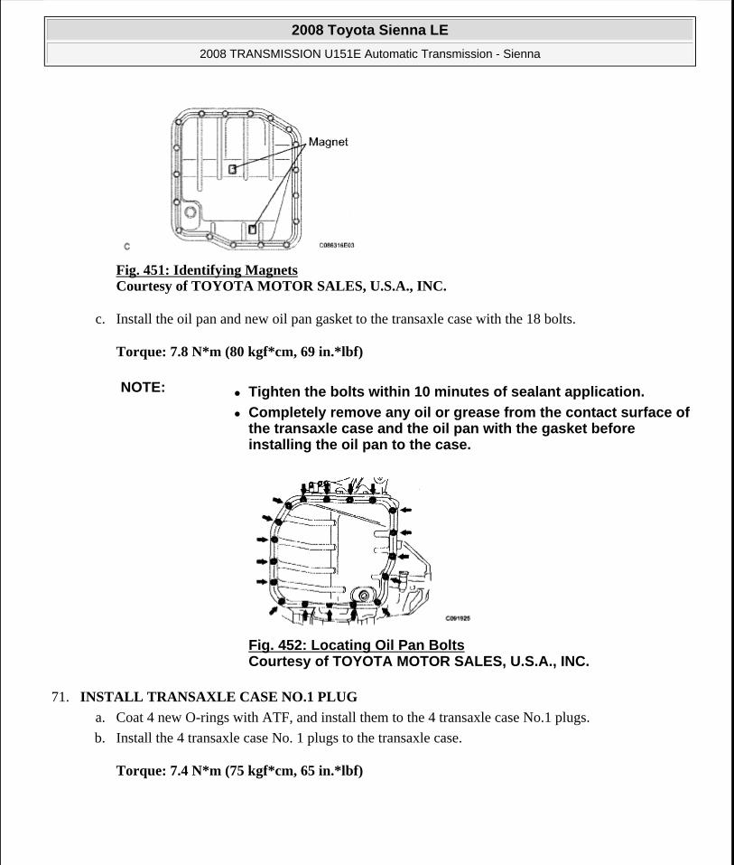
Fig. 451: Identifying Magnets Courtesy of TOYOTA MOTOR SALES, U.S.A., INC.
c. Install the oil pan and new oil pan gasket to the transaxle case with the 18 bolts.
Torque: 7.8 N*m (80 kgf*cm, 69 in.*lbf)
71. INSTALL TRANSAXLE CASE NO.1 PLUG
a. Coat 4 new O-rings with ATF, and install them to the 4 transaxle case No.1 plugs.
b. Install the 4 transaxle case No. 1 plugs to the transaxle case.
Torque: 7.4 N*m (75 kgf*cm, 65 in.*lbf)
NOTE: Tighten the bolts within 10 minutes of sealant application.
Completely remove any oil or grease from the contact surface of the transaxle case and the oil pan with the gasket before installing the oil pan to the case.
Fig. 452: Locating Oil Pan Bolts Courtesy of TOYOTA MOTOR SALES, U.S.A., INC.
2008 Toyota Sienna LE
2008 TRANSMISSION U151E Automatic Transmission - Sienna
Microsoft
Wednesday, August 12, 2009 2:03:30 PM Page 351 © 2005 Mitchell Repair Information Company, LLC.

Fig. 453: Identifying O-Rings And Transaxle Case No.1 Plugs Courtesy of TOYOTA MOTOR SALES, U.S.A., INC.
72. INSTALL SPEED SENSOR
a. Coat 2 new O-rings with ATF and install them to the 2 sensors.
b. Install the 2 sensors to the transaxle case with the 2 bolts.
Torque: 11.0 N*m (115 kgf*cm, 8 ft.*lbf)
Fig. 454: Identifying Speed Sensors Courtesy of TOYOTA MOTOR SALES, U.S.A., INC.
73. INSTALL OIL COOLER TUBE UNION (OUTLET OIL COOLER UNION)
a. Coat a new O-ring with ATF, and install it to the elbow.
b. Install the elbow to the transaxle case.
Torque: 27 N*m (276 kgf*cm, 20 ft.*lbf)
2008 Toyota Sienna LE
2008 TRANSMISSION U151E Automatic Transmission - Sienna
Microsoft
Wednesday, August 12, 2009 2:03:30 PM Page 352 © 2005 Mitchell Repair Information Company, LLC.

Fig. 455: Identifying Elbow And O-Ring Courtesy of TOYOTA MOTOR SALES, U.S.A., INC.
74. INSTALL OIL COOLER TUBE UNION (INLET OIL COOLER UNION)
a. Coat a new O-ring with ATF, and install it to the union.
b. Install the union to the transaxle case.
Torque: 25 N*m (255 kgf*cm, 18 ft.*lbf)
Fig. 456: Identifying Oil Cooler Tube Union (Inlet Oil Cooler Union) And O-Ring Courtesy of TOYOTA MOTOR SALES, U.S.A., INC.
75. INSTALL BREATHER PLUG HOSE
a. Install the breather plug hose to the transaxle case firmly.
76. INSTALL PARK/NEUTRAL POSITION SWITCH ASSEMBLY
a. Install the park/neutral position switch onto the manual valve lever shaft, and temporarily install the 2 adjusting bolts.
b. Install a new nut stopper and nut.
Torque: 6.9 N*m (70 kgf*cm, 61 in.*lbf)
2008 Toyota Sienna LE
2008 TRANSMISSION U151E Automatic Transmission - Sienna
Microsoft
Wednesday, August 12, 2009 2:03:30 PM Page 353 © 2005 Mitchell Repair Information Company, LLC.

Fig. 457: Locating Park/Neutral Position Switch Bolts Courtesy of TOYOTA MOTOR SALES, U.S.A., INC.
c. Temporarily install the control shaft lever.
Fig. 458: Identifying Control Shaft Lever Courtesy of TOYOTA MOTOR SALES, U.S.A., INC.
d. Turn the lever counterclockwise until it stops, and then turn it clockwise 2 notches.
e. Remove the control shaft lever.
Fig. 459: Turning Control Shaft Lever Counterclockwise And Clockwise Courtesy of TOYOTA MOTOR SALES, U.S.A., INC.
f. Align the groove with the neutral basic line.
g. Tighten the 2 bolts.
2008 Toyota Sienna LE
2008 TRANSMISSION U151E Automatic Transmission - Sienna
Microsoft
Wednesday, August 12, 2009 2:03:30 PM Page 354 © 2005 Mitchell Repair Information Company, LLC.

Torque: 5.4 N*m (55 kgf*cm, 48 in.*lbf)
Fig. 460: Identifying Park/Neutral Position Switch Bolts Groove Courtesy of TOYOTA MOTOR SALES, U.S.A., INC.
h. Using a screwdriver, stake the nut with the nut stopper.
Fig. 461: Staking Nut With Nut Stopper Courtesy of TOYOTA MOTOR SALES, U.S.A., INC.
i. Install the control shaft lever, washer and nut.
Torque: 13 N*m (130 kgf*cm, 9 ft.*lbf)
77. INSTALL SPEEDOMETER DRIVEN HOLE (ATM) COVER SUB-ASSEMBLY
a. Coat a new O-ring with ATF and install it to the speedometer driven hole cover.
b. Install the bolt and speedometer driven hole cover sub assembly to the transaxle assembly.
Torque: 6.9 N*m (70 kgf*cm, 61 in.*lbf)
2008 Toyota Sienna LE
2008 TRANSMISSION U151E Automatic Transmission - Sienna
Microsoft
Wednesday, August 12, 2009 2:03:30 PM Page 355 © 2005 Mitchell Repair Information Company, LLC.

Fig. 462: Locating Control Shaft Lever Nut Courtesy of TOYOTA MOTOR SALES, U.S.A., INC.
OIL PUMP
COMPONENTS
2008 Toyota Sienna LE
2008 TRANSMISSION U151E Automatic Transmission - Sienna
Microsoft
Wednesday, August 12, 2009 2:03:30 PM Page 356 © 2005 Mitchell Repair Information Company, LLC.

Fig. 463: Identifying Oil Pump Components With Torque SpecificationCourtesy of TOYOTA MOTOR SALES, U.S.A., INC.
DISASSEMBLY
1. INSPECT OIL PUMP ASSEMBLY
HINT:
(See INSPECTION )
2. REMOVE CLUTCH DRUM OIL SEAL RING
a. Remove the 2 clutch drum oil seal rings.
Fig. 464: Identifying Clutch Drum Oil Seal Rings Courtesy of TOYOTA MOTOR SALES, U.S.A., INC.
3. REMOVE STATOR SHAFT ASSEMBLY
a. Using a "torx" socket (T30), remove the 11 bolts and stator shaft.
4. INSPECT CLEARANCE OF OIL PUMP ASSEMBLY
HINT:
(See INSPECTION )
Fig. 465: Locating Stator Shaft Assembly Bolts Courtesy of TOYOTA MOTOR SALES, U.S.A., INC.
2008 Toyota Sienna LE
2008 TRANSMISSION U151E Automatic Transmission - Sienna
Microsoft
Wednesday, August 12, 2009 2:03:30 PM Page 357 © 2005 Mitchell Repair Information Company, LLC.

5. REMOVE FRONT OIL PUMP DRIVE GEAR
a. Remove the front oil pump drive gear.
Fig. 466: Locating Front Oil Pump Drive Gear Courtesy of TOYOTA MOTOR SALES, U.S.A., INC.
6. REMOVE FRONT OIL PUMP DRIVEN GEAR
a. Remove the front oil pump driven gear.
Fig. 467: Locating Front Oil Pump Driven Gear Courtesy of TOYOTA MOTOR SALES, U.S.A., INC.
7. REMOVE FRONT OIL PUMP BODY O-RING
a. Using a screwdriver, remove the O-ring.
HINT:
Tape the screwdriver before use.
2008 Toyota Sienna LE
2008 TRANSMISSION U151E Automatic Transmission - Sienna
Microsoft
Wednesday, August 12, 2009 2:03:30 PM Page 358 © 2005 Mitchell Repair Information Company, LLC.

Fig. 468: Using Screwdriver To Remove O-Ring Courtesy of TOYOTA MOTOR SALES, U.S.A., INC.
8. REMOVE FRONT OIL PUMP OIL SEAL
a. Mount the oil pump in a soft jaw vise.
b. Using SST, remove the oil seal from the oil pump body.
SST 09308-00010
Fig. 469: Removing Oil Seal From Oil Pump Body Using SST Courtesy of TOYOTA MOTOR SALES, U.S.A., INC.
INSPECTION
1. INSPECT OIL PUMP ASSEMBLY
a. Turn the drive gear with the 2 screwdrivers and make sure that it rotates smoothly.
NOTE: Be careful not to damage the oil seal lip.
2008 Toyota Sienna LE
2008 TRANSMISSION U151E Automatic Transmission - Sienna
Microsoft
Wednesday, August 12, 2009 2:03:30 PM Page 359 © 2005 Mitchell Repair Information Company, LLC.

Fig. 470: Turning Drive Gear With Screwdrivers Courtesy of TOYOTA MOTOR SALES, U.S.A., INC.
2. INSPECT CLEARANCE OF OIL PUMP ASSEMBLY
a. Push the driven gear to one side of the body.
b. Using a feeler gauge, measure the clearance.
Standard body clearance: 0.10 to 0.17 mm (0.0039 to 0.0067 in.)
Side clearance: 0.02 to 0.05 mm (0.001 to 0.002 in.)
Maximum body clearance: 0.17 mm (0.0067 in.)
If the body clearance is greater than the maximum, replace the oil pump body sub-assembly.
Fig. 471: Measuring Clearance Between Oil Pump Body And Oil Pump Driven Gear Courtesy of TOYOTA MOTOR SALES, U.S.A., INC.
c. Using a feeler gauge, measure the tip clearance between the driven gear teeth and drive gear teeth.
Standard tip clearance: 0.07 to 0.15 mm (0.0028 to 0.0059 in.)
Maximum tip clearance: 0.15 mm (0.0059 in.)
If the tip clearance is greater than the maximum, replace the oil pump body sub-assembly.
2008 Toyota Sienna LE
2008 TRANSMISSION U151E Automatic Transmission - Sienna
Microsoft
Wednesday, August 12, 2009 2:03:30 PM Page 360 © 2005 Mitchell Repair Information Company, LLC.

Fig. 472: Measuring Tip Clearance Between Driven Gear Teeth And Drive Gear Teeth Courtesy of TOYOTA MOTOR SALES, U.S.A., INC.
d. Using a straightedge and feeler gauge, measure the side clearance of both gears.
Standard side clearance: 0.02 to 0.05 mm (0.0008 to 0.0020 in.)
Maximum side clearance: 0.05 mm (0.0020 in.)
Drive gear thickness: mm (in.)
DRIVE GEAR THICKNESS SPECIFICATION
Fig. 473: Measuring Side Clearance Of Both Gears Courtesy of TOYOTA MOTOR SALES, U.S.A., INC.
Driven gear thickness: mm (in.)
DRIVE GEAR THICKNESS SPECIFICATION
Mark ThicknessA 11.690 to 11.699 (0.4602 to 0.4606)B 11.700 to 11.709 (0.4606 to 0.4610)C 11.710 to 11.720 (0.4610 to 0.4614)D 11.721 to 11.730 (0.4615 to 0.4618)E 11.731 to 11.740 (0.4619 to 0.4622)
Mark ThicknessA 11.690 to 11.699 (0.4602 to 0.4606)
2008 Toyota Sienna LE
2008 TRANSMISSION U151E Automatic Transmission - Sienna
Microsoft
Wednesday, August 12, 2009 2:03:30 PM Page 361 © 2005 Mitchell Repair Information Company, LLC.

3. INSPECT FRONT OIL PUMP AND GEAR BODY SUB-ASSEMBLY
a. Using a dial indicator, measure the inside diameter of the oil pump body bushing.
Standard inside diameter: 38.113 to 38.138 mm (1.50051 to 1.50149 in.)
Maximum inside diameter: 38.188 mm (1.50346 in.)
If the inside diameter is greater than the maximum, replace the oil pump body sub-assembly.
Fig. 474: Measuring Inside Diameter Of Oil Pump Body Bushing Courtesy of TOYOTA MOTOR SALES, U.S.A., INC.
4. INSPECT STATOR SHAFT ASSEMBLY
a. Using a dial indicator, measure the inside diameter of the stator shaft.
Standard inside diameter: 21.500 to 21.526 mm (0.84646 to 0.84748 in.)
Maximum inside diameter: 21.57 mm (0.8492 in.)
If the inside diameter is greater than the maximum, replace the stator shaft.
Fig. 475: Measuring Inside Diameter Of Stator Shaft
B 11.700 to 11.709 (0.4606 to 0.4610)C 11.710 to 11.720 (0.4610 to 0.4614)D 11.721 to 11.730 (0.4615 to 0.4618)E 11.731 to 11.740 (0.4619 to 0.4622)
2008 Toyota Sienna LE
2008 TRANSMISSION U151E Automatic Transmission - Sienna
Microsoft
Wednesday, August 12, 2009 2:03:30 PM Page 362 © 2005 Mitchell Repair Information Company, LLC.

Courtesy of TOYOTA MOTOR SALES, U.S.A., INC.
REASSEMBLY
1. INSTALL FRONT OIL PUMP OIL SEAL
a. Using SST and a hammer, install a new oil seal to the oil pump body.
SST 09350-32014(09351-32140)
HINT:
The seal end should be flat with the outer edge of the oil pump.
b. Coat the lip of the oil seal with MP grease.
Fig. 476: Tapping Oil Seal To Oil Pump Body Using SST Courtesy of TOYOTA MOTOR SALES, U.S.A., INC.
2. INSTALL FRONT OIL PUMP BODY O-RING
a. Coat new O-ring with ATF, and install it to the oil pump body.
Fig. 477: Identifying Front Oil Pump Body O-Ring Courtesy of TOYOTA MOTOR SALES, U.S.A., INC.
NOTE: Make sure that the O-ring is not twisted or pinched. Moreover, apply enough ATF to the O-ring before installation.
2008 Toyota Sienna LE
2008 TRANSMISSION U151E Automatic Transmission - Sienna
Microsoft
Wednesday, August 12, 2009 2:03:30 PM Page 363 © 2005 Mitchell Repair Information Company, LLC.

3. INSTALL FRONT OIL PUMP DRIVEN GEAR
a. Coat the front oil pump driven gear with ATF, and install it to the oil pump body with the marked side facing upward.
Fig. 478: Identifying Marks On Oil Pump Driven Gear Courtesy of TOYOTA MOTOR SALES, U.S.A., INC.
4. INSTALL FRONT OIL PUMP DRIVE GEAR
a. Coat the front oil pump drive gear with ATF, and install it to the oil pump body with the marked side facing upward.
Fig. 479: Identifying Marks On Oil Pump Drive Gear Courtesy of TOYOTA MOTOR SALES, U.S.A., INC.
5. INSTALL STATOR SHAFT ASSEMBLY
a. Set the stator shaft and align it with each bolt hole.
b. Using a "torx" socket (T30), install the 11 bolts.
Torque: 9.8 N*m (100 kgf*cm, 87 in.*lbf)
2008 Toyota Sienna LE
2008 TRANSMISSION U151E Automatic Transmission - Sienna
Microsoft
Wednesday, August 12, 2009 2:03:30 PM Page 364 © 2005 Mitchell Repair Information Company, LLC.

Fig. 480: Locating Stator Shaft Assembly Bolts Courtesy of TOYOTA MOTOR SALES, U.S.A., INC.
6. INSTALL CLUTCH DRUM OIL SEAL RING
a. Coat 2 new clutch drum oil seal rings with ATF.
b. Install 2 new clutch drum oil seal rings.
7. INSPECT OIL PUMP ASSEMBLY
HINT:
(See INSPECTION )
Fig. 481: Identifying Clutch Drum Oil Seal Rings Courtesy of TOYOTA MOTOR SALES, U.S.A., INC.
SECOND BRAKE PISTON
COMPONENTS
NOTE: Do not expand the ring ends excessively.
2008 Toyota Sienna LE
2008 TRANSMISSION U151E Automatic Transmission - Sienna
Microsoft
Wednesday, August 12, 2009 2:03:30 PM Page 365 © 2005 Mitchell Repair Information Company, LLC.

Fig. 482: Identifying Second Brake Piston Components Courtesy of TOYOTA MOTOR SALES, U.S.A., INC.
DISASSEMBLY
1. REMOVE 2ND BRAKE PISTON RETURN SPRING SUB-ASSEMBLY
a. Place SST on the return spring and compress the return spring with a press.
SST 09387-00060
b. Using a screwdriver, remove the snap ring.
2008 Toyota Sienna LE
2008 TRANSMISSION U151E Automatic Transmission - Sienna
Microsoft
Wednesday, August 12, 2009 2:03:30 PM Page 366 © 2005 Mitchell Repair Information Company, LLC.

Fig. 483: Compressing 2nd Brake Piston Return Spring And Locating Snap Ring Courtesy of TOYOTA MOTOR SALES, U.S.A., INC.
c. Remove the 2nd brake piston return spring.
Fig. 484: Identifying 2nd Brake Piston Return Spring Courtesy of TOYOTA MOTOR SALES, U.S.A., INC.
2. REMOVE 2ND BRAKE PISTON
a. Hold the 2nd brake piston and apply compressed air (392 kPa, 4.0 kgf/cm2 , 57 psi) to the 2nd brake cylinder to remove the 2nd brake piston.
NOTE: Hold the piston with a shop rag or a piece of cloth when removing the piston. Failure to do so may result in the piston jumping out from the cylinder.
2008 Toyota Sienna LE
2008 TRANSMISSION U151E Automatic Transmission - Sienna
Microsoft
Wednesday, August 12, 2009 2:03:30 PM Page 367 © 2005 Mitchell Repair Information Company, LLC.

Fig. 485: Applying Compressed Air To 2nd Brake CylinderCourtesy of TOYOTA MOTOR SALES, U.S.A., INC.
3. REMOVE 2ND BRAKE PISTON O-RING
a. Remove the 2 O-rings from the 2nd brake piston.
Fig. 486: Locating 2nd Brake Piston O-Rings Courtesy of TOYOTA MOTOR SALES, U.S.A., INC.
INSPECTION
1. INSPECT 2ND BRAKE PISTON RETURN SPRING SUB-ASSEMBLY
a. Using vernier calipers, measure the free length of the spring together with the spring seat.
Standard free length: 16.61 mm (0.6539 in.)
Fig. 487: Measuring Free Length Of 2nd Brake Piston Return Spring Courtesy of TOYOTA MOTOR SALES, U.S.A., INC.
REASSEMBLY
1. INSTALL 2ND BRAKE PISTON O-RING
a. Coat 2 new O-rings with ATF, and install them in the 2nd brake piston.
NOTE: Make sure that the O-ring is not twisted or pinched.
2008 Toyota Sienna LE
2008 TRANSMISSION U151E Automatic Transmission - Sienna
Microsoft
Wednesday, August 12, 2009 2:03:30 PM Page 368 © 2005 Mitchell Repair Information Company, LLC.

Fig. 488: Locating 2nd Brake Piston O-Rings Courtesy of TOYOTA MOTOR SALES, U.S.A., INC.
2. INSTALL 2ND BRAKE PISTON
a. Coat the 2nd brake piston with ATF, and install it to the 2nd brake cylinder.
Fig. 489: Locating 2nd Brake Piston Courtesy of TOYOTA MOTOR SALES, U.S.A., INC.
3. INSTALL 2ND BRAKE PISTON RETURN SPRING SUB-ASSEMBLY
a. Install the 2nd brake piston return spring.
Fig. 490: Identifying 2nd Brake Piston Return Spring Courtesy of TOYOTA MOTOR SALES, U.S.A., INC.
NOTE: Be careful not to damage the O-ring.
NOTE: Installing the spring sub- assembly, check that all of the springs are fit in the piston correctly.
2008 Toyota Sienna LE
2008 TRANSMISSION U151E Automatic Transmission - Sienna
Microsoft
Wednesday, August 12, 2009 2:03:30 PM Page 369 © 2005 Mitchell Repair Information Company, LLC.
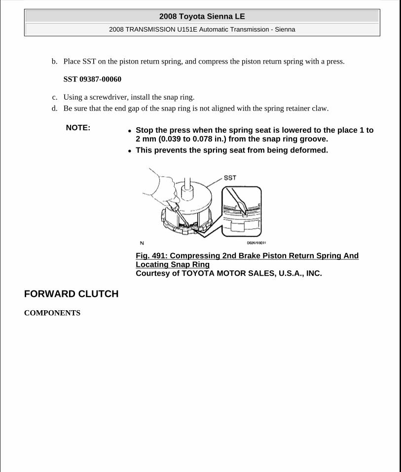
b. Place SST on the piston return spring, and compress the piston return spring with a press.
SST 09387-00060
c. Using a screwdriver, install the snap ring.
d. Be sure that the end gap of the snap ring is not aligned with the spring retainer claw.
FORWARD CLUTCH
COMPONENTS
NOTE: Stop the press when the spring seat is lowered to the place 1 to 2 mm (0.039 to 0.078 in.) from the snap ring groove.
This prevents the spring seat from being deformed.
Fig. 491: Compressing 2nd Brake Piston Return Spring And Locating Snap Ring Courtesy of TOYOTA MOTOR SALES, U.S.A., INC.
2008 Toyota Sienna LE
2008 TRANSMISSION U151E Automatic Transmission - Sienna
Microsoft
Wednesday, August 12, 2009 2:03:30 PM Page 370 © 2005 Mitchell Repair Information Company, LLC.

Fig. 492: Identifying Forward Clutch Components Courtesy of TOYOTA MOTOR SALES, U.S.A., INC.
DISASSEMBLY
1. INSPECT PACK CLEARANCE OF FORWARD CLUTCH
HINT:
2008 Toyota Sienna LE
2008 TRANSMISSION U151E Automatic Transmission - Sienna
Microsoft
Wednesday, August 12, 2009 2:03:30 PM Page 371 © 2005 Mitchell Repair Information Company, LLC.

(See INSPECTION )
2. REMOVE FORWARD MULTIPLE DISC CLUTCH DISC
a. Using a screwdriver, remove the snap ring.
Fig. 493: Identifying Snap Ring Courtesy of TOYOTA MOTOR SALES, U.S.A., INC.
b. Remove the flange, 5 discs and 5 plates from the input shaft assembly.
Fig. 494: Identifying Flange, Discs And Plates Courtesy of TOYOTA MOTOR SALES, U.S.A., INC.
3. REMOVE FORWARD CLUTCH RETURN SPRING SUB-ASSEMBLY
a. Place SST on the spring retainer and compress the return spring with a press.
b. Using a snap ring expander, remove the snap ring.
NOTE: Stop the press when the spring seat is lowered 1 to 2 mm (0.039 to 0.078 in.) from the snap ring groove, preventing the spring seat from being deformed.
Do not expand the snap ring excessively.
2008 Toyota Sienna LE
2008 TRANSMISSION U151E Automatic Transmission - Sienna
Microsoft
Wednesday, August 12, 2009 2:03:30 PM Page 372 © 2005 Mitchell Repair Information Company, LLC.

c. Remove the clutch balancer from the input shaft.
Fig. 496: Identifying Clutch Balancer And Input Shaft Courtesy of TOYOTA MOTOR SALES, U.S.A., INC.
d. Remove the forward clutch return spring from the input shaft.
Fig. 497: Identifying Forward Clutch Return Spring And Input Shaft Courtesy of TOYOTA MOTOR SALES, U.S.A., INC.
4. REMOVE FORWARD CLUTCH RETURN SPRING SUB-ASSEMBLY
a. Place the forward clutch drum onto the oil pump.
b. Holding the forward clutch piston by hand, apply compressed air (392 kPa, 4.0 kgf/cm2 , 57 psi) to
Fig. 495: Compressing Spring Retainer Using SST And Press To Locate Snap Ring Courtesy of TOYOTA MOTOR SALES, U.S.A., INC.
2008 Toyota Sienna LE
2008 TRANSMISSION U151E Automatic Transmission - Sienna
Microsoft
Wednesday, August 12, 2009 2:03:30 PM Page 373 © 2005 Mitchell Repair Information Company, LLC.

the oil pump to remove the forward clutch piston.
HINT:
When the piston cannot be removed as it is slanted, blow air again with the protruding side pushed, or remove the piston using the needle nose pliers with vinyl tape on the tip.
Fig. 498: Applying Compressed Air To Oil Pump Courtesy of TOYOTA MOTOR SALES, U.S.A., INC.
5. REMOVE INPUT SHAFT OIL SEAL RING
a. Remove the input shaft oil seal ring from the input shaft.
Fig. 499: Identifying Input Shaft Oil Seal Ring Courtesy of TOYOTA MOTOR SALES, U.S.A., INC.
INSPECTION
1. INSPECT PACK CLEARANCE OF FORWARD CLUTCH
a. Install the forward clutch on the oil pump.
b. Using a dial indicator, measure the forward clutch pack clearance while applying and releasing compressed air (392 kPa, 4.0 kgf/cm2 , 57 psi).
NOTE: Be careful not to damage the oil seal ring of oil pump.
2008 Toyota Sienna LE
2008 TRANSMISSION U151E Automatic Transmission - Sienna
Microsoft
Wednesday, August 12, 2009 2:03:31 PM Page 374 © 2005 Mitchell Repair Information Company, LLC.

Pack clearance: 1.00 to 1.25 mm (0.0394 to 0.4921 in.)
If the clearance is not as specified, inspect the discs, plates and flange.
HINT:
If the opening is large, cover it with a shop rug or a piece of cloth to prevent the compressed air from being released.
Fig. 500: Measuring Forward Clutch Pack Clearance Courtesy of TOYOTA MOTOR SALES, U.S.A., INC.
2. INSPECT FORWARD MULTIPLE DISC CLUTCH DISC
a. Check if the sliding surface of the disc, plate and flange are worn or burnt.
If necessary, replace them.
HINT:
If the lining of the disc comes off or discolors, or if a part of the groove is worn, replace all discs.
Before installing new discs, immerse them in ATF for at least 15 minutes.
2008 Toyota Sienna LE
2008 TRANSMISSION U151E Automatic Transmission - Sienna
Microsoft
Wednesday, August 12, 2009 2:03:31 PM Page 375 © 2005 Mitchell Repair Information Company, LLC.

Fig. 501: Identifying Forward Multiple Disc Clutch Disc Courtesy of TOYOTA MOTOR SALES, U.S.A., INC.
3. INSPECT FORWARD CLUTCH RETURN SPRING SUB-ASSEMBLY
a. Using vernier calipers, measure the free length of the spring together with the spring seat.
Standard free length: 26.74 mm (1.0528 in.)
Fig. 502: Measuring Free Length Of Forward Clutch Return Spring Courtesy of TOYOTA MOTOR SALES, U.S.A., INC.
4. INSPECT PACK CLEARANCE OF FORWARD CLUTCH
a. Using a dial indicator, measure the forward clutch pack clearance while applying and releasing compressed air (392 kgf/cm2 , 4.0 kPa, 57 psi).
Pack clearance: 1.00 to 1.25 mm (0.0394 to 0.4921 in.)
If the piston stroke is less than the minimum, parts may be assembled incorrectly. Check and reassemble the parts again.
If the clearance is not as specified, select another flange.
HINT:
There are 5 different thicknesses of flanges available.
Flange thickness: mm (in.)
2008 Toyota Sienna LE
2008 TRANSMISSION U151E Automatic Transmission - Sienna
Microsoft
Wednesday, August 12, 2009 2:03:31 PM Page 376 © 2005 Mitchell Repair Information Company, LLC.

FLANGE THICKNESS SPECIFICATION
Fig. 503: Measuring Forward Clutch Pack Clearance Courtesy of TOYOTA MOTOR SALES, U.S.A., INC.
5. INSPECT FORWARD MULTIPLE DISC CLUTCH DISC
a. Check if the disc lightly rotates when rotating the forward clutch assembly after inserting the multiple disc clutch into it.
Fig. 504: Inspecting Forward Multiple Disc Clutch Disc
No. Thickness No. Thickness1 3.00(0.1181) 4 3.45(0.1358)2 3.15(0.1240) 5 3.60 (0.1417)3 3.30 (0.1299) - -
NOTE: Do not place the forward clutch assembly in a vise.
2008 Toyota Sienna LE
2008 TRANSMISSION U151E Automatic Transmission - Sienna
Microsoft
Wednesday, August 12, 2009 2:03:31 PM Page 377 © 2005 Mitchell Repair Information Company, LLC.

Courtesy of TOYOTA MOTOR SALES, U.S.A., INC.
REASSEMBLY
1. INSTALL INPUT SHAFT OIL SEAL RING
a. Compress a new input shaft oil seal ring from both sides to reduce dimension A.
Dimension A: 5 mm (0.197 in.)
b. Coat the oil seal ring with ATF and install it to the input shaft.
Fig. 505: Compressing New Input Shaft Oil Seal Ring From Both Sides To Reduce Dimension A Courtesy of TOYOTA MOTOR SALES, U.S.A., INC.
2. INSTALL FORWARD CLUTCH PISTON SUB-ASSEMBLY
a. Coat the forward clutch piston with ATF, and install it to the input shaft.
Fig. 506: Identifying Forward Clutch Piston Sub-Assembly Courtesy of TOYOTA MOTOR SALES, U.S.A., INC.
NOTE: Do not expand the end gap of the oil seal ring too much. Fix the hooks firmly.
NOTE: Be careful not to damage the lip of the forward clutch piston.
2008 Toyota Sienna LE
2008 TRANSMISSION U151E Automatic Transmission - Sienna
Microsoft
Wednesday, August 12, 2009 2:03:31 PM Page 378 © 2005 Mitchell Repair Information Company, LLC.

3. INSTALL FORWARD CLUTCH RETURN SPRING SUB-ASSEMBLY
a. Install the return spring to the input shaft.
b. Coat the clutch balancer with ATF.
Fig. 507: Identifying Forward Clutch Return Spring And Input Shaft Courtesy of TOYOTA MOTOR SALES, U.S.A., INC.
c. Install the clutch balancer to the input shaft.
d. Place SST on the clutch balancer, and compress the clutch balancer with a press.
SST 09387-00020
NOTE: Installing the spring sub-assembly, check that all of the springs are fit in the piston correctly.
NOTE: Be careful not to damage the lip of the forward clutch balancer.
Make sure that the clutch balancer is not pinched and that there are no other defects at the lip.
Apply sufficient ATF to the sealing lip before installation.
Fig. 508: Identifying Clutch Balancer And Input Shaft Courtesy of TOYOTA MOTOR SALES, U.S.A., INC.
2008 Toyota Sienna LE
2008 TRANSMISSION U151E Automatic Transmission - Sienna
Microsoft
Wednesday, August 12, 2009 2:03:31 PM Page 379 © 2005 Mitchell Repair Information Company, LLC.

e. Install the snap ring with a snap ring expander.
f. Be sure that the end gap of the snap ring is not aligned with the spring retainer claw.
g. Set the end gap of the snap ring in the piston as shown in the illustration.
4. INSTALL FORWARD MULTIPLE DISC CLUTCH DISC
a. Coat the 5 discs with ATF.
Fig. 510: Identifying Stoppers Courtesy of TOYOTA MOTOR SALES, U.S.A., INC.
b. Install the 5 plates, 5 discs and flange input shaft.
NOTE: Stop the press when the spring seat is lowered to the place 1 to 2 mm (0.039 to 0.078 in.) from the snap ring groove.
This prevents the spring seat from being deformed.
Do not expand the snap ring excessively.
Fig. 509: Installing Snap Ring Courtesy of TOYOTA MOTOR SALES, U.S.A., INC.
NOTE: The end gap of the snap ring should not align with any of the stoppers.
NOTE: Make sure that the plates, discs, and flange are installed as shown in
2008 Toyota Sienna LE
2008 TRANSMISSION U151E Automatic Transmission - Sienna
Microsoft
Wednesday, August 12, 2009 2:03:31 PM Page 380 © 2005 Mitchell Repair Information Company, LLC.

Fig. 511: Identifying Plates, Discs And Flange Courtesy of TOYOTA MOTOR SALES, U.S.A., INC.
c. Using a screwdriver, install the snap ring.
d. Check that the end gap of the snap ring is not aligned with one of the cutouts.
Fig. 512: Identifying Snap Ring Courtesy of TOYOTA MOTOR SALES, U.S.A., INC.
5. INSPECT PACK CLEARANCE OF FORWARD CLUTCH
HINT:
(See INSPECTION )
6. INSPECT FORWARD MULTIPLE DISC CLUTCH DISC
HINT:
(See INSPECTION )
DIRECT CLUTCH
the illustration.
NOTE: The snap ring should be fully engaged in the groove of the drum.
2008 Toyota Sienna LE
2008 TRANSMISSION U151E Automatic Transmission - Sienna
Microsoft
Wednesday, August 12, 2009 2:03:31 PM Page 381 © 2005 Mitchell Repair Information Company, LLC.
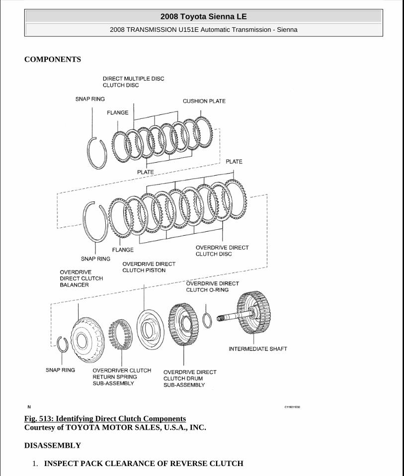
COMPONENTS
Fig. 513: Identifying Direct Clutch Components Courtesy of TOYOTA MOTOR SALES, U.S.A., INC.
DISASSEMBLY
1. INSPECT PACK CLEARANCE OF REVERSE CLUTCH
2008 Toyota Sienna LE
2008 TRANSMISSION U151E Automatic Transmission - Sienna
Microsoft
Wednesday, August 12, 2009 2:03:31 PM Page 382 © 2005 Mitchell Repair Information Company, LLC.

HINT:
(See INSPECTION )
2. INSPECT PACK CLEARANCE OF DIRECT CLUTCH AND OVERDRIVE CLUTCH
HINT:
(See INSPECTION )
3. REMOVE DIRECT MULTIPLE DISC CLUTCH DISC
a. Using a screwdriver, remove the snap ring from the intermediate shaft.
Fig. 514: Identifying Snap Ring Courtesy of TOYOTA MOTOR SALES, U.S.A., INC.
b. Remove the flange, 3 discs, 3 plates and cushion plate from the intermediate shaft.
Fig. 515: Identifying Flange, Discs, Plates And Cushion Plate From Intermediate Shaft Courtesy of TOYOTA MOTOR SALES, U.S.A., INC.
4. REMOVE OVERDRIVE DIRECT CLUTCH DISC
a. Using a screwdriver, remove the snap ring from the intermediate shaft.
b. Remove the flange, 4 discs and 4 plates from the intermediate shaft.
2008 Toyota Sienna LE
2008 TRANSMISSION U151E Automatic Transmission - Sienna
Microsoft
Wednesday, August 12, 2009 2:03:31 PM Page 383 © 2005 Mitchell Repair Information Company, LLC.

Fig. 516: Identifying Flange, Discs And Plates From Intermediate Shaft Courtesy of TOYOTA MOTOR SALES, U.S.A., INC.
5. REMOVE OVERDRIVE CLUTCH RETURN SPRING SUB-ASSEMBLY
a. Place SST on the clutch balancer and compress the spring with a press.
SST 09387-00020
b. Using a snap ring expander, remove the snap ring from the direct clutch drum.
c. Remove the clutch balancer from the direct clutch drum.
NOTE: Stop the press when the spring seat is lowered to the place 1 to 2 mm (0.039 to 0.078 in.) from the snap ring groove.
Fig. 517: Placing SST On Clutch Balancer And Compress Overdrive Clutch Return Spring Courtesy of TOYOTA MOTOR SALES, U.S.A., INC.
This prevents the spring seat from being deformed.
Do not expand the snap ring excessively.
2008 Toyota Sienna LE
2008 TRANSMISSION U151E Automatic Transmission - Sienna
Microsoft
Wednesday, August 12, 2009 2:03:31 PM Page 384 © 2005 Mitchell Repair Information Company, LLC.

Fig. 518: Identifying Clutch Balancer And Direct Clutch Drum Courtesy of TOYOTA MOTOR SALES, U.S.A., INC.
d. Remove the overdrive clutch return spring from the direct clutch drum.
Fig. 519: Identifying Overdrive Clutch Return Spring And Direct Clutch Drum Courtesy of TOYOTA MOTOR SALES, U.S.A., INC.
6. REMOVE OVERDRIVE DIRECT CLUTCH PISTON
a. Install the intermediate shaft on the transaxle rear cover.
b. Holding the direct clutch piston with your hand, apply compressed air (392 kPa, 4.0 kgf/cm2 , 57 psi) to the transaxle rear cover to remove the direct clutch piston.
Fig. 520: Applying Compressed Air To Transaxle Rear Cover Courtesy of TOYOTA MOTOR SALES, U.S.A., INC.
7. REMOVE OVERDRIVE DIRECT CLUTCH DRUM SUB-ASSEMBLY
2008 Toyota Sienna LE
2008 TRANSMISSION U151E Automatic Transmission - Sienna
Microsoft
Wednesday, August 12, 2009 2:03:31 PM Page 385 © 2005 Mitchell Repair Information Company, LLC.

a. Holding the direct clutch drum by hand, apply compressed air (392 kPa, 4.0 kgf/cm2 , 57 psi) to the transaxle rear cover to remove the direct clutch drum.
Fig. 521: Applying Compressed Air To Transaxle Rear Cover Courtesy of TOYOTA MOTOR SALES, U.S.A., INC.
8. REMOVE OVERDRIVE DIRECT CLUTCH O-RING
a. Using a screwdriver, remove the O-ring from the direct clutch drum.
Fig. 522: Locating Overdrive Direct Clutch O-Ring Courtesy of TOYOTA MOTOR SALES, U.S.A., INC.
INSPECTION
1. INSPECT PACK CLEARANCE OF REVERSE CLUTCH
a. Install the intermediate shaft and needle roller bearing onto the transaxle rear cover.
b. Using a dial indicator, measure the reverse clutch pack clearance while applying and releasing compressed air (392 kPa, 4.0 kgf/cm2 , 57 psi).
Pack clearance: 0.60 to 0.82 mm (0.02362 to 0.03228 in.)
If the pack clearance is not as specified, inspect the discs, plates and flange.
2008 Toyota Sienna LE
2008 TRANSMISSION U151E Automatic Transmission - Sienna
Microsoft
Wednesday, August 12, 2009 2:03:31 PM Page 386 © 2005 Mitchell Repair Information Company, LLC.

Fig. 523: Measuring Reverse Clutch Pack Clearance Courtesy of TOYOTA MOTOR SALES, U.S.A., INC.
2. INSPECT PACK CLEARANCE OF DIRECT CLUTCH AND OVERDRIVE CLUTCH
a. Using a dial indicator, measure the direct clutch and overdrive clutch pack clearance while applyingand releasing compressed air (392 kPa, 4.0 kgf/cm2 , 57 psi).
Pack clearance: 0.61 to 0.83 mm (0.02401 to 0.03268 in.)
If the pack clearance is not as specified, inspect the discs, plates and flange.
2008 Toyota Sienna LE
2008 TRANSMISSION U151E Automatic Transmission - Sienna
Microsoft
Wednesday, August 12, 2009 2:03:31 PM Page 387 © 2005 Mitchell Repair Information Company, LLC.

Fig. 524: Measuring Direct Clutch And Overdrive Clutch Pack Clearance Courtesy of TOYOTA MOTOR SALES, U.S.A., INC.
3. INSPECT DIRECT MULTIPLE DISC CLUTCH DISC
a. Check if the sliding surfaces of the disc, plate and flange are worn or burnt.
If necessary, replace them.
HINT:
If the lining of the disc comes off or discolors, or if a part of the groove is worn, replace all discs.
Before installing new discs, immerse them in ATF for at least 15 minutes.
Fig. 525: Identifying Direct Multiple Disc Clutch Disc Courtesy of TOYOTA MOTOR SALES, U.S.A., INC.
2008 Toyota Sienna LE
2008 TRANSMISSION U151E Automatic Transmission - Sienna
Microsoft
Wednesday, August 12, 2009 2:03:31 PM Page 388 © 2005 Mitchell Repair Information Company, LLC.

4. INSPECT OVERDRIVE DIRECT CLUTCH DISC
a. Check if the sliding surface of the disc, plate and flange are worn or burnt.
If necessary, replace them.
HINT:
If the lining of the disc comes off or discolors, or if a part of the groove is worn, replace all discs.
Before installing new discs, immerse them in ATF for at least 15 minutes.
Fig. 526: Identifying Overdrive Direct Clutch Disc Courtesy of TOYOTA MOTOR SALES, U.S.A., INC.
5. INSPECT OVERDRIVE CLUTCH RETURN SPRING SUB-ASSEMBLY
a. Using vernier calipers, measure the free length of the spring together with the spring seat.
Standard free length: 25.91 mm (1.0201 in.)
Fig. 527: Measuring Free Length Of Overdrive Clutch Return Spring Courtesy of TOYOTA MOTOR SALES, U.S.A., INC.
6. INSPECT PACK CLEARANCE OF REVERSE CLUTCH
a. Install the intermediate shaft onto the transaxle rear cover.
b. Using a dial indicator, measure the direct clutch pack clearance while applying and releasing compressed air (392 kPa, 4.0 kgf/cm2 , 57 psi).
2008 Toyota Sienna LE
2008 TRANSMISSION U151E Automatic Transmission - Sienna
Microsoft
Wednesday, August 12, 2009 2:03:31 PM Page 389 © 2005 Mitchell Repair Information Company, LLC.

Clearance: 0.60 to 0.82 mm (0.02362 to 0.03228 in.)
If the pack clearance is less than the minimum, parts may have been assembled incorrectly, so check and reassemble again. If the clearance is not as specified, select another flange.
HINT:
There are 7 flanges of different thickness.
Flange thickness: mm (in.)
FLANGE THICKNESS SPECIFICATION
Fig. 528: Measuring Reverse Clutch Pack Clearance Courtesy of TOYOTA MOTOR SALES, U.S.A., INC.
7. INSPECT PACK CLEARANCE OF DIRECT CLUTCH AND OVERDRIVE CLUTCH
a. Using a dial indicator, measure the direct clutch & overdrive clutch pack clearance while applying and releasing compressed air (392 kPa, 4.0 kgf/cm2 , 57 psi).
Clearance: 0.61 to 0.83 mm (0.02401 to 0.03268 in.)
No. Thickness No. Thickness1 3.0(0.118) 5 3.4(0.134)2 3.1 (0.122) 6 3.5(0.138)3 3.2 (0.126) 7 3.6 (0.142)4 3.3(0.130) - -
2008 Toyota Sienna LE
2008 TRANSMISSION U151E Automatic Transmission - Sienna
Microsoft
Wednesday, August 12, 2009 2:03:31 PM Page 390 © 2005 Mitchell Repair Information Company, LLC.

If the pack clearance is less than the minimum, parts may have been assembled incorrectly, so check and reassemble again. If the clearance is not as specified, select another flange.
HINT:
There are 7 different thicknesses of flanges available.
Flange thickness: mm (in.)
FLANGE THICKNESS SPECIFICATION
b. Check that the disc rotates when rotating the disc after inserting the rear planetary sun gear.
Fig. 529: Checking Disc Rotation Courtesy of TOYOTA MOTOR SALES, U.S.A., INC.
REASSEMBLY
1. INSTALL OVERDRIVE DIRECT CLUTCH O-RING
a. Coat an O-ring with ATF, and install it to the direct clutch drum.
No. Thickness No. Thickness0 2.5 (0.098) 4 2.9 (0.114)1 2.6 (0.102) 5 3.0(0.118)2 2.7(0.106) 6 3.1 (0.122)3 2.8(0.110) - -
NOTE: Do not place the rear planetary sun gear in a vise.
NOTE: Make sure that the O-ring is not twisted or pinched when it is installed.
2008 Toyota Sienna LE
2008 TRANSMISSION U151E Automatic Transmission - Sienna
Microsoft
Wednesday, August 12, 2009 2:03:31 PM Page 391 © 2005 Mitchell Repair Information Company, LLC.

Fig. 530: Locating Overdrive Direct Clutch O-Ring Courtesy of TOYOTA MOTOR SALES, U.S.A., INC.
2. INSTALL OVERDRIVE DIRECT CLUTCH DRUM SUB-ASSEMBLY
a. Coat the direct clutch drum with ATF, and install it to the intermediate shaft.
3. INSTALL OVERDRIVE DIRECT CLUTCH PISTON
a. Coat the overdrive direct clutch piston with ATF, and install it to the direct clutch drum.
Fig. 532: Identifying Overdrive Direct Clutch Piston Courtesy of TOYOTA MOTOR SALES, U.S.A., INC.
NOTE: Be careful not to damage the O-ring.
Be careful not to damage the lip of the direct clutch drum.
Fig. 531: Identifying Direct Clutch Drum And Intermediate ShaftCourtesy of TOYOTA MOTOR SALES, U.S.A., INC.
2008 Toyota Sienna LE
2008 TRANSMISSION U151E Automatic Transmission - Sienna
Microsoft
Wednesday, August 12, 2009 2:03:31 PM Page 392 © 2005 Mitchell Repair Information Company, LLC.

4. INSTALL OVERDRIVE CLUTCH RETURN SPRING SUB-ASSEMBLY
a. Install the overdrive clutch return spring to the direct clutch drum.
b. Coat the clutch balancer with ATF.
Fig. 533: Identifying Overdrive Clutch Return Spring And Direct Clutch Drum Courtesy of TOYOTA MOTOR SALES, U.S.A., INC.
c. Install the clutch balancer to the direct clutch drum.
d. Place SST on the clutch balancer and compress the overdrive clutch return spring with a press.
SST 09387-00020
NOTE: Installing the spring sub-assembly, check that all of the springs are fit in piston correctly.
NOTE: Be careful not to damage the lip of the direct clutch balancer.
Make sure that the lip of the seal is not pinched and that it has no other defects.
Apply sufficient ATF to the sealing lip before installing the clutch balancer.
Fig. 534: Identifying Clutch Balancer And Direct Clutch Drum Courtesy of TOYOTA MOTOR SALES, U.S.A., INC.
2008 Toyota Sienna LE
2008 TRANSMISSION U151E Automatic Transmission - Sienna
Microsoft
Wednesday, August 12, 2009 2:03:31 PM Page 393 © 2005 Mitchell Repair Information Company, LLC.

e. Using a snap ring expander, install the snap ring to the direct clutch drum.
f. Be sure that the end gap of the snap ring is not aligned with the spring retainer claw.
g. Set the end gap of the snap ring in the piston shown in the illustration.
Fig. 536: Identifying Stoppers Courtesy of TOYOTA MOTOR SALES, U.S.A., INC.
5. INSTALL OVERDRIVE DIRECT CLUTCH DISC
a. Coat the 4 discs with ATF.
b. Install the 4 plates, 4 discs and flange to the intermediate shaft.
NOTE: Stop the press when the spring seat is lowered to the place 1 to 2 mm (0.039 to 0.078 in.) from the snap ring groove.
This prevents the spring seat from being deformed.
Do not expand the snap ring excessively.
Fig. 535: Placing SST On Clutch Balancer And Compress Overdrive Clutch Return Spring Courtesy of TOYOTA MOTOR SALES, U.S.A., INC.
NOTE: The end gap of the snap ring should not align with any of the stoppers.
NOTE: Make sure that the plates, discs, and flange are installed as shown in
2008 Toyota Sienna LE
2008 TRANSMISSION U151E Automatic Transmission - Sienna
Microsoft
Wednesday, August 12, 2009 2:03:31 PM Page 394 © 2005 Mitchell Repair Information Company, LLC.

Fig. 537: Identifying Plates, Discs And Flange Courtesy of TOYOTA MOTOR SALES, U.S.A., INC.
c. Using a screwdriver, install the snap ring.
d. Check that the end gap of the snap ring is not aligned with one of the cutouts.
Fig. 538: Locating Snap Ring Courtesy of TOYOTA MOTOR SALES, U.S.A., INC.
6. INSTALL DIRECT MULTIPLE DISC CLUTCH DISC
a. Coat the 3 disc with ATF.
b. Install the cushion plate, 3 plates, 3 disc and flange to the intermediate shaft.
the illustration.
NOTE: The snap ring should be fully engaged in the groove of the drum.
NOTE: Install the cushion plate with the mark on the white surface facing to plate.
Be careful about the order of discs, plate and flange assembly.
2008 Toyota Sienna LE
2008 TRANSMISSION U151E Automatic Transmission - Sienna
Microsoft
Wednesday, August 12, 2009 2:03:31 PM Page 395 © 2005 Mitchell Repair Information Company, LLC.

c. Using a screwdriver, install the snap ling.
d. Check that the end gap of the snap ling is not aligned with one of the cutouts.
Fig. 540: Locating Snap Ring Courtesy of TOYOTA MOTOR SALES, U.S.A., INC.
UNDERDRIVE PLANETARY GEAR
COMPONENTS
Fig. 539: Identifying Cushion Plate, Plates, Disc And Flange Courtesy of TOYOTA MOTOR SALES, U.S.A., INC.
NOTE: The slap ring should be fixed certainly in the groove of the drum.
2008 Toyota Sienna LE
2008 TRANSMISSION U151E Automatic Transmission - Sienna
Microsoft
Wednesday, August 12, 2009 2:03:31 PM Page 396 © 2005 Mitchell Repair Information Company, LLC.

Fig. 541: Identifying Underdrive Planetary Gear Components With Torque Specifications Courtesy of TOYOTA MOTOR SALES, U.S.A., INC.
DISASSEMBLY
1. INSPECT UNDERDRIVE PLANETARY GEAR PRELOAD
HINT:
(See INSPECTION )
2. REMOVE FRONT PLANETARY GEAR NUT
2008 Toyota Sienna LE
2008 TRANSMISSION U151E Automatic Transmission - Sienna
Microsoft
Wednesday, August 12, 2009 2:03:31 PM Page 397 © 2005 Mitchell Repair Information Company, LLC.

a. Using SST, loosen the staked part of the lock nut.
SST 09930-00010 (09931 -00010, 09931 -00020), 09387-00050
Fig. 542: Loosening Staked Part Of Lock Nut Courtesy of TOYOTA MOTOR SALES, U.S.A., INC.
b. Place the underdrive planetary gear in a soft jaw vise.
Fig. 543: Placing Underdrive Planetary Gear In Soft Jaw Vise Courtesy of TOYOTA MOTOR SALES, U.S.A., INC.
c. Using a socket wrench, remove the lock nut.
Fig. 544: Locating Lock Nut
NOTE: Be careful not to damage the differential drive pinion.
2008 Toyota Sienna LE
2008 TRANSMISSION U151E Automatic Transmission - Sienna
Microsoft
Wednesday, August 12, 2009 2:03:31 PM Page 398 © 2005 Mitchell Repair Information Company, LLC.

Courtesy of TOYOTA MOTOR SALES, U.S.A., INC.
3. REMOVE CYLINDRICAL ROLLER BEARING RACE INNER
a. Using SST, remove the cylindrical roller bearing race inner.
SST 09950-00020, 09950-00030, 09950-60010 (09951-00320, 09957-04010)
Fig. 545: Using SST On Cylindrical Roller Bearing Race Inner Courtesy of TOYOTA MOTOR SALES, U.S.A., INC.
4. REMOVE UNDERDRIVE PLANETARY GEAR ASSEMBLY
a. Using SST and a press, remove the differential drive pinion, parking lock gear, counter driven gear with underdrive planetary ring gear and radial ball bearing front.
SST 09950-60010 (09951 -00320), 09387-00050, 09950-00020, 09950-00030, 09950-40011 (09957-04010)
Fig. 546: Pressing Differential Drive Pinion, Parking Lock Gear And Counter Driven Gear With SST Courtesy of TOYOTA MOTOR SALES, U.S.A., INC.
b. Place the underdrive planetary gear in a soft jaw vise.
c. Using SST, remove the radial ball bearing rear from the underdrive planetary gear.
SST 09950-60010 (09951 -00320), 09950-00030, 09950-40011 (09957-04010)
2008 Toyota Sienna LE
2008 TRANSMISSION U151E Automatic Transmission - Sienna
Microsoft
Wednesday, August 12, 2009 2:03:31 PM Page 399 © 2005 Mitchell Repair Information Company, LLC.

Fig. 547: Using SST To Remove Rear Bearing Form Underdrive Planetary Gear Courtesy of TOYOTA MOTOR SALES, U.S.A., INC.
5. REMOVE UNDERDRIVE PLANETARY RING GEAR
a. Using a snap ring pliers, remove the snap ring.
Fig. 548: Locating Snap Ring Courtesy of TOYOTA MOTOR SALES, U.S.A., INC.
b. Remove the underdrive planetary ring gear from the counter driven gear.
Fig. 549: Identifying Underdrive Planetary Ring Gear And Counter Driven Gear Courtesy of TOYOTA MOTOR SALES, U.S.A., INC.
INSPECTION
1. INSPECT UNDERDRIVE PLANETARY GEAR PRELOAD
2008 Toyota Sienna LE
2008 TRANSMISSION U151E Automatic Transmission - Sienna
Microsoft
Wednesday, August 12, 2009 2:03:31 PM Page 400 © 2005 Mitchell Repair Information Company, LLC.
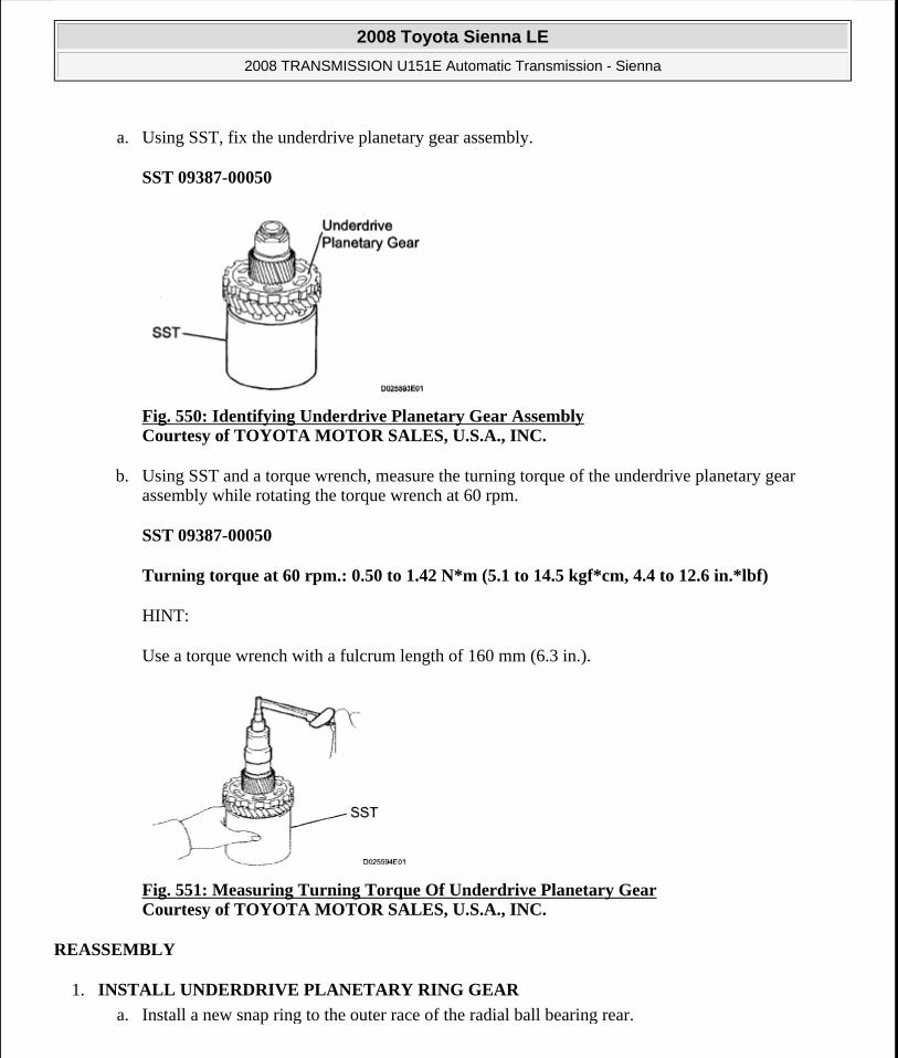
a. Using SST, fix the underdrive planetary gear assembly.
SST 09387-00050
Fig. 550: Identifying Underdrive Planetary Gear Assembly Courtesy of TOYOTA MOTOR SALES, U.S.A., INC.
b. Using SST and a torque wrench, measure the turning torque of the underdrive planetary gear assembly while rotating the torque wrench at 60 rpm.
SST 09387-00050
Turning torque at 60 rpm.: 0.50 to 1.42 N*m (5.1 to 14.5 kgf*cm, 4.4 to 12.6 in.*lbf)
HINT:
Use a torque wrench with a fulcrum length of 160 mm (6.3 in.).
Fig. 551: Measuring Turning Torque Of Underdrive Planetary Gear Courtesy of TOYOTA MOTOR SALES, U.S.A., INC.
REASSEMBLY
1. INSTALL UNDERDRIVE PLANETARY RING GEAR
a. Install a new snap ring to the outer race of the radial ball bearing rear.
2008 Toyota Sienna LE
2008 TRANSMISSION U151E Automatic Transmission - Sienna
Microsoft
Wednesday, August 12, 2009 2:03:31 PM Page 401 © 2005 Mitchell Repair Information Company, LLC.

HINT:
When replacing the bearing, also replace the counter driven gear with a new one.
Fig. 552: Identifying Snap Ring On Outer Race Of Radial Ball Bearing Rear Courtesy of TOYOTA MOTOR SALES, U.S.A., INC.
b. Using a piston ring compressor, squeeze the snap ring.
Fig. 553: Using Piston Ring Compressor To Squeeze Snap Ring Courtesy of TOYOTA MOTOR SALES, U.S.A., INC.
c. Using SST and a press, press in the outer race of the radial ball bearing rear.
SST 09950-60020 (09951 -00890), 09950-70010 (09951-07100)
Fig. 554: Pressing In Outer Race Of Radial Ball Bearing Rear
NOTE: Be sure not to damage the snap ring during outer race installation.
2008 Toyota Sienna LE
2008 TRANSMISSION U151E Automatic Transmission - Sienna
Microsoft
Wednesday, August 12, 2009 2:03:31 PM Page 402 © 2005 Mitchell Repair Information Company, LLC.
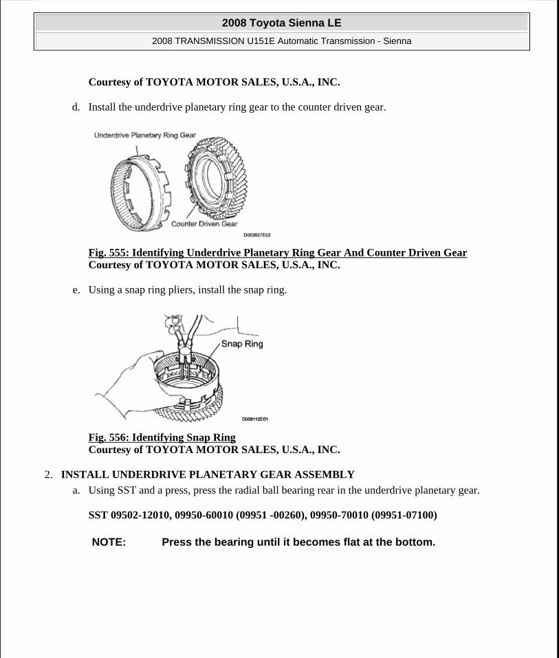
Courtesy of TOYOTA MOTOR SALES, U.S.A., INC.
d. Install the underdrive planetary ring gear to the counter driven gear.
Fig. 555: Identifying Underdrive Planetary Ring Gear And Counter Driven Gear Courtesy of TOYOTA MOTOR SALES, U.S.A., INC.
e. Using a snap ring pliers, install the snap ring.
Fig. 556: Identifying Snap Ring Courtesy of TOYOTA MOTOR SALES, U.S.A., INC.
2. INSTALL UNDERDRIVE PLANETARY GEAR ASSEMBLY
a. Using SST and a press, press the radial ball bearing rear in the underdrive planetary gear.
SST 09502-12010, 09950-60010 (09951 -00260), 09950-70010 (09951-07100)
NOTE: Press the bearing until it becomes flat at the bottom.
2008 Toyota Sienna LE
2008 TRANSMISSION U151E Automatic Transmission - Sienna
Microsoft
Wednesday, August 12, 2009 2:03:31 PM Page 403 © 2005 Mitchell Repair Information Company, LLC.

Fig. 557: Pressing Radial Ball Bearing Rear In Underdrive Planetary Gear Courtesy of TOYOTA MOTOR SALES, U.S.A., INC.
b. Install the counter driven gear with planetary ring gear to the underdrive planetary gear.
Fig. 558: Identifying Counter Driven Gear With Planetary Ring Gear Courtesy of TOYOTA MOTOR SALES, U.S.A., INC.
c. Using SST and a press, press in the radial ball bearing front.
SST 09502-12010, 09950-60010 (09951 -00260), 09950-70010 (09951-07100)
Fig. 559: Pressing In Radial Ball Bearing Front Courtesy of TOYOTA MOTOR SALES, U.S.A., INC.
NOTE: Press the counter driven gear while rotating it.
2008 Toyota Sienna LE
2008 TRANSMISSION U151E Automatic Transmission - Sienna
Microsoft
Wednesday, August 12, 2009 2:03:31 PM Page 404 © 2005 Mitchell Repair Information Company, LLC.

d. Using SST and a press, press in the parking lock gear.
SST 09502-12010, 09950-60010 (09951-00260), 09950-70010 (09951 -07100)
Fig. 560: Pressing Parking Lock Gear Courtesy of TOYOTA MOTOR SALES, U.S.A., INC.
3. INSTALL DIFFERENTIAL DRIVE PINION
a. Using SST and a press, press the differential drive pinion.
SST 09726-40010, 09950-60010 (09951 -00260), 09950-70010 (09951-07100)
Fig. 561: Pressing Differential Drive Pinion Courtesy of TOYOTA MOTOR SALES, U.S.A., INC.
4. INSTALL CYLINDRICAL ROLLER BEARING RACE INNER
a. Using SST and a press, press the cylindrical roller bearing race inner.
SST 09506-35010, 09950-60010 (09951 -00260), 09950-70010 (09951-07100)
NOTE: Press the counter driven gear while rotating it.
NOTE: Press the counter driven gear while rotating it.
NOTE: Press the counter driven gear while rotating it.
2008 Toyota Sienna LE
2008 TRANSMISSION U151E Automatic Transmission - Sienna
Microsoft
Wednesday, August 12, 2009 2:03:31 PM Page 405 © 2005 Mitchell Repair Information Company, LLC.

Fig. 562: Pressing Cylindrical Roller Bearing Race Inner Courtesy of TOYOTA MOTOR SALES, U.S.A., INC.
5. INSTALL FRONT PLANETARY GEAR NUT
a. Place the underdrive planetary gear in a soft jaw vise.
b. Using a socket wrench, install a new lock nut.
Torque: 280 N*m (2,885 kgf*cm, 207 ft.*lbf)
HINT:
Use a torque wrench with a fulcrum length of 750 mm (29.53 in.).
Fig. 563: Identifying Lock Nut Courtesy of TOYOTA MOTOR SALES, U.S.A., INC.
c. Using a pin punch and hammer, stake the lock nut.
NOTE: Be careful not to damage the differential drive pinion.
CAUTION: Be sure that there are no cracks on the nut.
2008 Toyota Sienna LE
2008 TRANSMISSION U151E Automatic Transmission - Sienna
Microsoft
Wednesday, August 12, 2009 2:03:31 PM Page 406 © 2005 Mitchell Repair Information Company, LLC.

Fig. 564: Staking Lock Nut Courtesy of TOYOTA MOTOR SALES, U.S.A., INC.
6. INSPECT UNDERDRIVE PLANETARY GEAR PRELOAD
HINT:
(See INSPECTION )
UNDERDRIVE CLUTCH
COMPONENTS
2008 Toyota Sienna LE
2008 TRANSMISSION U151E Automatic Transmission - Sienna
Microsoft
Wednesday, August 12, 2009 2:03:31 PM Page 407 © 2005 Mitchell Repair Information Company, LLC.

Fig. 565: Identifying Underdrive Clutch Components Courtesy of TOYOTA MOTOR SALES, U.S.A., INC.
DISASSEMBLY
1. INSPECT UNDERDRIVE PACK CLEARANCE
HINT:
(See INSPECTION )
2. REMOVE UNDERDRIVE CLUTCH FLANGE NO.2 HOLE SNAP RING
2008 Toyota Sienna LE
2008 TRANSMISSION U151E Automatic Transmission - Sienna
Microsoft
Wednesday, August 12, 2009 2:03:31 PM Page 408 © 2005 Mitchell Repair Information Company, LLC.

a. Using a screwdriver, remove the underdrive clutch flange No.2 snap ring.
Fig. 566: Identifying Underdrive Clutch Flange Hole Snap Ring Courtesy of TOYOTA MOTOR SALES, U.S.A., INC.
3. REMOVE UNDERDRIVE CLUTCH DISC NO.1
a. Remove the flange, 4 discs and 4 plates from the underdrive clutch drum.
Fig. 567: Identifying Discs, Plates, And Underdrive Clutch Drum Courtesy of TOYOTA MOTOR SALES, U.S.A., INC.
4. REMOVE UNDERDRIVE CLUTCH RETURN SPRING SUB-ASSEMBLY
a. Place SST on the clutch balancer and compress the spring with a press.
SST 09350-32014
b. Using a snap ring expander, remove the snap ring.
NOTE: Stop the press when the spring seat is lowered to the place 1 to 2 mm (0.039 to 0.078 in.) from the snap ring groove.
This prevents the spring seat from being deformed.
Do not expand the snap ring excessively.
2008 Toyota Sienna LE
2008 TRANSMISSION U151E Automatic Transmission - Sienna
Microsoft
Wednesday, August 12, 2009 2:03:32 PM Page 409 © 2005 Mitchell Repair Information Company, LLC.

c. Remove the clutch balancer from the underdrive clutch drum.
Fig. 569: View Of Clutch Balancer And Underdrive Clutch Drum Courtesy of TOYOTA MOTOR SALES, U.S.A., INC.
d. Remove the return spring from the underdrive clutch drum.
Fig. 570: View Of Underdrive Clutch Return Spring And Underdrive Clutch Drum Courtesy of TOYOTA MOTOR SALES, U.S.A., INC.
5. REMOVE UNDERDRIVE CLUTCH PISTON SET
a. Install the underdrive clutch to the transaxle case.
Fig. 568: Using Press And SST To Compress Spring To Locate Snap Ring Courtesy of TOYOTA MOTOR SALES, U.S.A., INC.
2008 Toyota Sienna LE
2008 TRANSMISSION U151E Automatic Transmission - Sienna
Microsoft
Wednesday, August 12, 2009 2:03:32 PM Page 410 © 2005 Mitchell Repair Information Company, LLC.

b. Holding the underdrive clutch piston by hand, apply compressed air (392 kPa, 4.0 kgf/cm2 , 57 psi) to the transaxle case to remove the underdrive clutch piston.
Fig. 571: Applying Compressed Air To Transaxle Case Courtesy of TOYOTA MOTOR SALES, U.S.A., INC.
6. REMOVE UNDERDRIVE CLUTCH DRUM O-RING
a. Using a screwdriver, remove the O-ring from the underdrive clutch drum.
Fig. 572: Locating Underdrive Clutch Drum O-Ring Courtesy of TOYOTA MOTOR SALES, U.S.A., INC.
INSPECTION
1. INSPECT UNDERDRIVE PACK CLEARANCE
a. Install the underdrive clutch to the transaxle case.
b. Install a dial indicator as shown in the illustration.
c. Measure the underdrive clutch pack clearance while applying and releasing compressed air (392 kPa, 4.0 kgf/cm2 , 57 psi).
Pack clearance: 1.51 to 1.71 mm (0.0594 to 0.0673 in.)
NOTE: Be careful not to damage the oil seal ring.
NOTE: Be careful not to damage the oil seal rings.
2008 Toyota Sienna LE
2008 TRANSMISSION U151E Automatic Transmission - Sienna
Microsoft
Wednesday, August 12, 2009 2:03:32 PM Page 411 © 2005 Mitchell Repair Information Company, LLC.

If the pack clearance is not as specified, inspect the discs, plates and flange.
HINT:
There are 5 flanges in different thickness.
Flange thickness: mm (in.)
FLANGE THICKNESS SPECIFICATION
Fig. 573: Measuring Underdrive Clutch Pack Clearance Courtesy of TOYOTA MOTOR SALES, U.S.A., INC.
2. INSPECT UNDERDRIVE CLUTCH DISC NO.1
a. Check if the sliding surface of the disc, plate and flange are worn or burnt. If necessary, replace them.
HINT:
If the lining of the disc comes off or discolors, or if a part of the groove is worn, replace all discs.
Before installing new discs, immerse them in ATF for at least 15 minutes.
Mark Thickness Mark Thickness1 3.0(0.118) 4 3.6 (0.122)2 3.2 (0.126) 5 3.8 (0.130)3 3.4(0.134) - -
2008 Toyota Sienna LE
2008 TRANSMISSION U151E Automatic Transmission - Sienna
Microsoft
Wednesday, August 12, 2009 2:03:32 PM Page 412 © 2005 Mitchell Repair Information Company, LLC.

Fig. 574: Identifying Underdrive Clutch Disc Courtesy of TOYOTA MOTOR SALES, U.S.A., INC.
3. INSPECT UNDERDRIVE CLUTCH DRUM SUB-ASSEMBLY
a. Using a dial indicator, measure the inside diameter of the underdrive clutch drum bushing.
Standard drum bushing: 37.06 to 37.08 mm (1.4591 to 1.4598 in.)
Maximum drum bushing: 37.13 mm (1.4618 in.)
If the inside diameter is greater than the maximum, replace the underdrive clutch drum.
Fig. 575: Measuring Inside Diameter Of Underdrive Clutch Drum Bushing Courtesy of TOYOTA MOTOR SALES, U.S.A., INC.
4. INSPECT UNDERDRIVE CLUTCH RETURN SPRING SUB-ASSEMBLY
a. Using a vernier calipers, measure the free length of the spring together with the spring seat.
Standard free length: 17.14 mm (0.6752 in.)
2008 Toyota Sienna LE
2008 TRANSMISSION U151E Automatic Transmission - Sienna
Microsoft
Wednesday, August 12, 2009 2:03:32 PM Page 413 © 2005 Mitchell Repair Information Company, LLC.

Fig. 576: Measuring Free Length Of Underdrive Clutch Return Spring Courtesy of TOYOTA MOTOR SALES, U.S.A., INC.
REASSEMBLY
1. INSTALL UNDERDRIVE CLUTCH DRUM O-RING
a. Coat a new O-ring with ATF, and install it to the underdrive clutch drum.
Fig. 577: Identifying Underdrive Clutch Drum O-Ring Courtesy of TOYOTA MOTOR SALES, U.S.A., INC.
2. INSTALL UNDERDRIVE CLUTCH PISTON SET
a. Coat the underdrive clutch piston with ATF, and install it to the underdrive clutch piston drum.
NOTE: Make sure that the O-ring is not twisted or pinched.
NOTE: Be careful not to damage the O-ring.
Be careful not to damage the lip of the piston.
2008 Toyota Sienna LE
2008 TRANSMISSION U151E Automatic Transmission - Sienna
Microsoft
Wednesday, August 12, 2009 2:03:32 PM Page 414 © 2005 Mitchell Repair Information Company, LLC.

3. INSTALL UNDERDRIVE CLUTCH RETURN SPRING SUB-ASSEMBLY
a. Install the return spring to the underdrive clutch drum.
b. Coat the clutch balancer with ATF.
Fig. 579: View Of Underdrive Clutch Return Spring And Underdrive Clutch Drum Courtesy of TOYOTA MOTOR SALES, U.S.A., INC.
c. Install the clutch balancer to the underdrive clutch drum.
Fig. 578: Locating Underdrive Clutch Piston Courtesy of TOYOTA MOTOR SALES, U.S.A., INC.
NOTE: Installing the spring sub-assembly, check that all of the springs are fit in the piston correctly.
NOTE: Be careful not to damage the lip of the clutch balancer.
2008 Toyota Sienna LE
2008 TRANSMISSION U151E Automatic Transmission - Sienna
Microsoft
Wednesday, August 12, 2009 2:03:32 PM Page 415 © 2005 Mitchell Repair Information Company, LLC.

Fig. 580: View Of Clutch Balancer And Underdrive Clutch Drum Courtesy of TOYOTA MOTOR SALES, U.S.A., INC.
d. Place SST on the clutch balancer and compress the piston return spring with a press.
SST 09350-32014(09351-32070)
e. Using a snap ring expander, install the snap ring to the underdrive clutch drum.
f. Be sure that the end gap of the snap ring is not aligned with the spring retainer claw.
g. Set the end gap of the snap ring in the underdrive clutch drum as shown in the illustration.
NOTE: Stop the press when the spring seat is lowered to the place 1 to 2 mm (0.039 to 0.078 in.) from the snap ring groove.
This prevents the spring seat from being deformed.
Do not expand the snap ring excessively.
Fig. 581: Using Press And SST To Compress Spring To Locate Snap Ring Courtesy of TOYOTA MOTOR SALES, U.S.A., INC.
NOTE: The end gap of the snap ring should not align with any of the stoppers.
2008 Toyota Sienna LE
2008 TRANSMISSION U151E Automatic Transmission - Sienna
Microsoft
Wednesday, August 12, 2009 2:03:32 PM Page 416 © 2005 Mitchell Repair Information Company, LLC.

Fig. 582: Identifying Stoppers Courtesy of TOYOTA MOTOR SALES, U.S.A., INC.
4. INSTALL UNDERDRIVE CLUTCH DISC NO.1
a. Coat the 4 discs with ATF.
b. Install the 4 plates, 4 discs and flange to the underdrive clutch drum.
Fig. 583: Identifying Plates, Discs And Flange Courtesy of TOYOTA MOTOR SALES, U.S.A., INC.
5. INSTALL 1ST & REVERSE BRAKE RETURN SPRING SHAFT SNAP RING
a. Using a screwdriver, install the underdrive clutch flange No.2 hole snap ring.
b. Check that the end gap of snap ring is not aligned with one of the cutouts.
6. INSPECT UNDERDRIVE PACK CLEARANCE
HINT:
(See INSPECTION )
NOTE: Make sure that the plates, discs, and flange are installed as shown in the illustration.
NOTE: The snap ring should be fully engaged in the groove of the drum.
2008 Toyota Sienna LE
2008 TRANSMISSION U151E Automatic Transmission - Sienna
Microsoft
Wednesday, August 12, 2009 2:03:32 PM Page 417 © 2005 Mitchell Repair Information Company, LLC.

Fig. 584: Identifying Underdrive Clutch Flange Hole Snap Ring Courtesy of TOYOTA MOTOR SALES, U.S.A., INC.
DIFFERENTIAL CASE
COMPONENTS
2008 Toyota Sienna LE
2008 TRANSMISSION U151E Automatic Transmission - Sienna
Microsoft
Wednesday, August 12, 2009 2:03:32 PM Page 418 © 2005 Mitchell Repair Information Company, LLC.

Fig. 585: Identifying Differential Case Components With Torque Specifications Courtesy of TOYOTA MOTOR SALES, U.S.A., INC.
DISASSEMBLY
1. REMOVE FRONT DIFFERENTIAL RING GEAR
a. Place matchmarks on the front differential ring gear and differential case.
2008 Toyota Sienna LE
2008 TRANSMISSION U151E Automatic Transmission - Sienna
Microsoft
Wednesday, August 12, 2009 2:03:32 PM Page 419 © 2005 Mitchell Repair Information Company, LLC.

Fig. 586: Identifying Matchmarks On Front Differential Ring Gear And Differential Case Courtesy of TOYOTA MOTOR SALES, U.S.A., INC.
b. Remove the 14 bolts.
Fig. 587: Identifying Front Differential Ring Gear Bolts Courtesy of TOYOTA MOTOR SALES, U.S.A., INC.
c. Using a plastic hammer, tap on the front differential ring gear to remove it from the case.
Fig. 588: Tapping On Front Differential Ring Gear Courtesy of TOYOTA MOTOR SALES, U.S.A., INC.
2. REMOVE FRONT DIFFERENTIAL CASE FRONT TAPERED ROLLER BEARING
a. Using SST, remove the front differential case front differential tapered roller bearing from the differential case.
2008 Toyota Sienna LE
2008 TRANSMISSION U151E Automatic Transmission - Sienna
Microsoft
Wednesday, August 12, 2009 2:03:32 PM Page 420 © 2005 Mitchell Repair Information Company, LLC.

SST 09950-00020, 09950-00030, 09950-60010 (09951-00490), 09950-40011 (09957-04010)
Fig. 589: Using SST To Remove Front Differential Case Front Differential Tapered Roller Bearing From Differential Case Courtesy of TOYOTA MOTOR SALES, U.S.A., INC.
b. Using SST, remove the front differential case front tapered roller bearing outer race.
SST 09308-00010
Fig. 590: Using SST To Remove Front Differential Case Front Tapered Roller Bearing Outer Race Courtesy of TOYOTA MOTOR SALES, U.S.A., INC.
3. REMOVE FRONT DIFFERENTIAL CASE REAR TAPERED ROLLER BEARING
a. Using SST, remove the front differential case rear tapered roller bearing from the differential case.
SST 09950-00020, 09950-00030, 09950-60010 (09951-00490), 09950-40011 (09957- 04010), 09308-00010
2008 Toyota Sienna LE
2008 TRANSMISSION U151E Automatic Transmission - Sienna
Microsoft
Wednesday, August 12, 2009 2:03:32 PM Page 421 © 2005 Mitchell Repair Information Company, LLC.

Fig. 591: Using SST To Remove Front Differential Case Rear Tapered Roller Bearing From Differential Case Courtesy of TOYOTA MOTOR SALES, U.S.A., INC.
b. Using SST, remove the front differential case rear tapered roller bearing outer race.
SST 09308-00010
Fig. 592: Using SST To Remove Front Differential Case Rear Tapered Roller Bearing Outer Race Courtesy of TOYOTA MOTOR SALES, U.S.A., INC.
4. REMOVE FRONT DIFFERENTIAL PINION SHAFT STRAIGHT PIN
a. Using a pin punch and hammer, install the straight pin.
NOTE: Before removing the straight pin, unstake it with a pin punch.
2008 Toyota Sienna LE
2008 TRANSMISSION U151E Automatic Transmission - Sienna
Microsoft
Wednesday, August 12, 2009 2:03:32 PM Page 422 © 2005 Mitchell Repair Information Company, LLC.
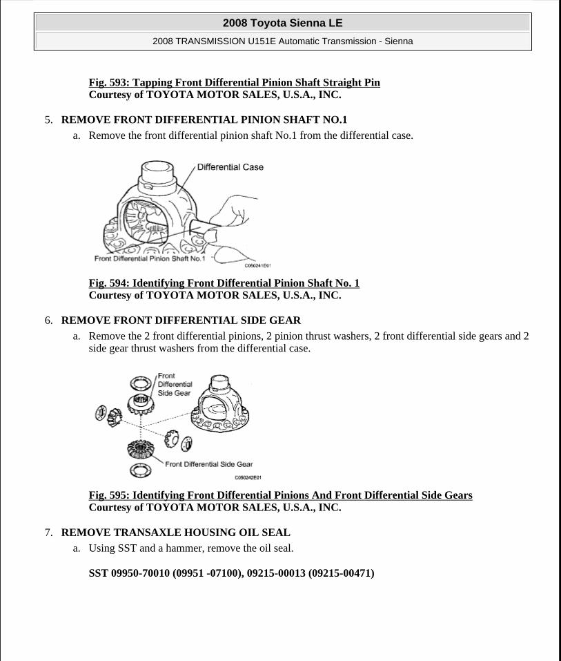
Fig. 593: Tapping Front Differential Pinion Shaft Straight PinCourtesy of TOYOTA MOTOR SALES, U.S.A., INC.
5. REMOVE FRONT DIFFERENTIAL PINION SHAFT NO.1
a. Remove the front differential pinion shaft No.1 from the differential case.
Fig. 594: Identifying Front Differential Pinion Shaft No. 1 Courtesy of TOYOTA MOTOR SALES, U.S.A., INC.
6. REMOVE FRONT DIFFERENTIAL SIDE GEAR
a. Remove the 2 front differential pinions, 2 pinion thrust washers, 2 front differential side gears and 2 side gear thrust washers from the differential case.
Fig. 595: Identifying Front Differential Pinions And Front Differential Side Gears Courtesy of TOYOTA MOTOR SALES, U.S.A., INC.
7. REMOVE TRANSAXLE HOUSING OIL SEAL
a. Using SST and a hammer, remove the oil seal.
SST 09950-70010 (09951 -07100), 09215-00013 (09215-00471)
2008 Toyota Sienna LE
2008 TRANSMISSION U151E Automatic Transmission - Sienna
Microsoft
Wednesday, August 12, 2009 2:03:32 PM Page 423 © 2005 Mitchell Repair Information Company, LLC.

Fig. 596: Tapping Transaxle Housing Oil Seal Courtesy of TOYOTA MOTOR SALES, U.S.A., INC.
8. REMOVE DIFFERENTIAL SIDE BEARING RETAINER OIL SEAL
a. Using SST, remove the oil seal.
SST 09950-70010 (09951 -07100), 09608-10010
Fig. 597: Tapping Out Oil Seal Courtesy of TOYOTA MOTOR SALES, U.S.A., INC.
INSPECTION
1. INSPECT BACKLASH
a. Using a dial indicator, inspect the backlash of the side gear.
Standard backlash: 0.05 to 0.20 mm (0.0020 to 0.0079 in.)
Thrust washer thickness
THRUST WASHER THICKNESS SPECIFICATION Mark Thickness
- 1.625 mm (0.0640 in.)- 1.725 mm (0.0679 in.)- 1.825 mm (0.0719 in.)
2008 Toyota Sienna LE
2008 TRANSMISSION U151E Automatic Transmission - Sienna
Microsoft
Wednesday, August 12, 2009 2:03:32 PM Page 424 © 2005 Mitchell Repair Information Company, LLC.
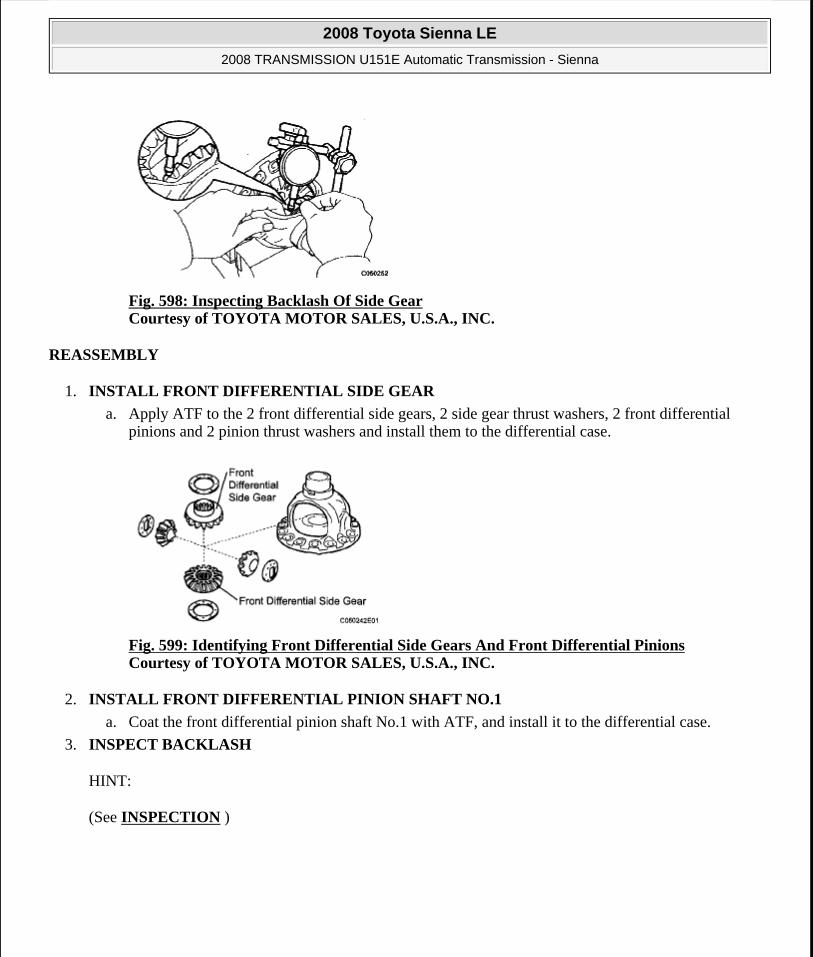
Fig. 598: Inspecting Backlash Of Side Gear Courtesy of TOYOTA MOTOR SALES, U.S.A., INC.
REASSEMBLY
1. INSTALL FRONT DIFFERENTIAL SIDE GEAR
a. Apply ATF to the 2 front differential side gears, 2 side gear thrust washers, 2 front differential pinions and 2 pinion thrust washers and install them to the differential case.
Fig. 599: Identifying Front Differential Side Gears And Front Differential Pinions Courtesy of TOYOTA MOTOR SALES, U.S.A., INC.
2. INSTALL FRONT DIFFERENTIAL PINION SHAFT NO.1
a. Coat the front differential pinion shaft No.1 with ATF, and install it to the differential case.
3. INSPECT BACKLASH
HINT:
(See INSPECTION )
2008 Toyota Sienna LE
2008 TRANSMISSION U151E Automatic Transmission - Sienna
Microsoft
Wednesday, August 12, 2009 2:03:32 PM Page 425 © 2005 Mitchell Repair Information Company, LLC.

Fig. 600: Identifying Front Differential Pinion Shaft No. 1 Courtesy of TOYOTA MOTOR SALES, U.S.A., INC.
4. INSTALL FRONT DIFFERENTIAL PINION SHAFT STRAIGHT PIN
a. Using a pin punch and a hammer, install the pinion shaft straight pin.
Fig. 601: Using Pin Punch And Hammer To Install Pinion Shaft Straight Pin Courtesy of TOYOTA MOTOR SALES, U.S.A., INC.
b. Using a chisel and a hammer, stake the differential case.
Fig. 602: Staking Differential Case Courtesy of TOYOTA MOTOR SALES, U.S.A., INC.
5. INSTALL FRONT DIFFERENTIAL CASE FRONT TAPERED ROLLER BEARING
NOTE: Stake the differential case after adjusting the backlash.
2008 Toyota Sienna LE
2008 TRANSMISSION U151E Automatic Transmission - Sienna
Microsoft
Wednesday, August 12, 2009 2:03:32 PM Page 426 © 2005 Mitchell Repair Information Company, LLC.

a. Using SST and a press, install the front differential case front tapered roller bearing to the differential case.
SST 09316-12010, 09550-60010 (09951 -00490), 09950-70010 (09951 -07100)
Fig. 603: Pressing Front Differential Case Front Tapered Roller Bearing Courtesy of TOYOTA MOTOR SALES, U.S.A., INC.
b. Using SST and a hammer, install the front differential case tapered roller bearing front outer race to the transaxle housing.
SST 09550-60010 (09951 -00490), 09950-60020 (09951-00910)
Fig. 604: Tapping Front Differential Case Tapered Roller Bearing Front Outer Race To Transaxle Housing Courtesy of TOYOTA MOTOR SALES, U.S.A., INC.
6. INSTALL FRONT DIFFERENTIAL CASE REAR TAPERED ROLLER BEARING
a. Using SST and a press, install the front differential case front tapered roller bearing to the differential case.
SST 09316-12010, 09550-60010 (09951-00490), 09950-70010 (09951-07100, 09951-07150)
NOTE: Do not damage the bearing cage when installing the bearing inner race.
2008 Toyota Sienna LE
2008 TRANSMISSION U151E Automatic Transmission - Sienna
Microsoft
Wednesday, August 12, 2009 2:03:32 PM Page 427 © 2005 Mitchell Repair Information Company, LLC.

Fig. 605: Using SST And Press To Install Front Differential Case Front Tapered Roller Bearing To Differential Case Courtesy of TOYOTA MOTOR SALES, U.S.A., INC.
b. Using SST and a hammer, install the front differential case tapered roller bearing rear outer race to the transaxle housing.
SST 09950-70010 (09951 -07100, 09951 -07150), 09950-60020 (09951-00890)
Fig. 606: Using SST And Hammer To Install Front Differential Case Tapered Roller Bearing Front Outer Race To Transaxle Housing Courtesy of TOYOTA MOTOR SALES, U.S.A., INC.
7. ADJUST DIFFERENTIAL SIDE BEARING PRELOAD
a. Install the differential assembly to the transaxle case.
NOTE: Do not damage the bearing cage when installing the bearing inner race.
NOTE: No clearance is allowed between the bearing and transaxle housing.
2008 Toyota Sienna LE
2008 TRANSMISSION U151E Automatic Transmission - Sienna
Microsoft
Wednesday, August 12, 2009 2:03:32 PM Page 428 © 2005 Mitchell Repair Information Company, LLC.

Fig. 607: Identifying Differential Gear Assembly Courtesy of TOYOTA MOTOR SALES, U.S.A., INC.
b. Clean the mating surfaces of the transaxle case and transaxle housing.
c. Install the transaxle housing to the transaxle case and tighten them with the 16 bolts.
Torque: Bolt A 25 N*m (255 kgf*cm, 18 ft.*lbf)
Bolt B 33 N*m (337 kgf*cm, 24 ft.*lbf)
Bolt C 29 N*m (295 kgf*cm, 21 ft.*lbf)
Bolt D 22 N*m (226 kgf*cm, 16.0 ft.*lbf)
Fig. 608: Locating Transaxle Housing Bolts Courtesy of TOYOTA MOTOR SALES, U.S.A., INC.
HINT:
Apply seal packing or equivalent to bolts A and D.
Seal packing: THREE BOND 2403 or equivalent
Bolt length:
Bolt A: 50 mm (1.969 in.)
2008 Toyota Sienna LE
2008 TRANSMISSION U151E Automatic Transmission - Sienna
Microsoft
Wednesday, August 12, 2009 2:03:32 PM Page 429 © 2005 Mitchell Repair Information Company, LLC.

Bolt B: 50 mm (1.969 in.)
Bolt C:
42 mm (1.654 in.)
Bolt D: 72 mm (2.835 in.)
HINT:
Usually, bolt A is non-reusable. In this case, however, the bolt can be used after cleaning it.
d. Using SST, turn the differential assembly to the right and left 2 or 3 times to settle the bearing.
SST 09564-32011
e. Using SST and a torque wrench, measure the turning torque of the differential.
SST 09564-32011
Turning torque at 60 rpm:
New bearing: 0.20 to 0.69 N*m (2.0 to 7.0 kgf*cm, 1.8 to 6.1 in.*lbf)
Used bearing: 0.10 to 0.35 N*m (1.0 to 3.6 kgf*cm, 0.9 to 3.1 in.*lbf)
HINT:
If the turning torque is not as specified, refer to the table below to select a thrust washer so that the specified value is achieved.
Flange thickness: mm (in.)
FLANGE THICKNESS SPECIFICATION Mark Thickness Mark Thickness
0 2.00 (0.0787) 9 2.45 (0.0965)1 2.05 (0.0807) A 2.50 (0.0984)2 2.10(0.0827) B 2.55(0.1004)3 2.15(0.0846) C 2.60 (0.1024)4 2.20 (0.0866) D 2.65 (0.1043)5 2.25 (0.0886) E 2.70 (0.1063)6 2.30 (0.0906) F 2.75 (0.1083)7 2.35 (0.0925) G 2.80 (0.1102)8 2.40 (0.0945) H 2.85(0.1122)
2008 Toyota Sienna LE
2008 TRANSMISSION U151E Automatic Transmission - Sienna
Microsoft
Wednesday, August 12, 2009 2:03:32 PM Page 430 © 2005 Mitchell Repair Information Company, LLC.

Fig. 609: Measuring Turning Torque Of Differential Courtesy of TOYOTA MOTOR SALES, U.S.A., INC.
f. Remove the 16 bolts and the transaxle housing.
Fig. 610: Locating Transaxle Housing Bolts Courtesy of TOYOTA MOTOR SALES, U.S.A., INC.
g. Remove the differential assembly.
2008 Toyota Sienna LE
2008 TRANSMISSION U151E Automatic Transmission - Sienna
Microsoft
Wednesday, August 12, 2009 2:03:32 PM Page 431 © 2005 Mitchell Repair Information Company, LLC.
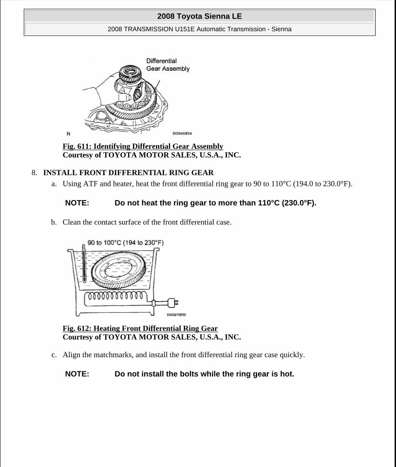
Fig. 611: Identifying Differential Gear Assembly Courtesy of TOYOTA MOTOR SALES, U.S.A., INC.
8. INSTALL FRONT DIFFERENTIAL RING GEAR
a. Using ATF and heater, heat the front differential ring gear to 90 to 110°C (194.0 to 230.0°F).
b. Clean the contact surface of the front differential case.
Fig. 612: Heating Front Differential Ring Gear Courtesy of TOYOTA MOTOR SALES, U.S.A., INC.
c. Align the matchmarks, and install the front differential ring gear case quickly.
NOTE: Do not heat the ring gear to more than 110°C (230.0°F).
NOTE: Do not install the bolts while the ring gear is hot.
2008 Toyota Sienna LE
2008 TRANSMISSION U151E Automatic Transmission - Sienna
Microsoft
Wednesday, August 12, 2009 2:03:32 PM Page 432 © 2005 Mitchell Repair Information Company, LLC.

Fig. 613: Identifying Matchmarks On Front Differential Ring Gear And Differential Case Courtesy of TOYOTA MOTOR SALES, U.S.A., INC.
d. Tighten the 14 bolts.
Torque: 95.0 N*m (970 kgf*cm, 70 ft.*lbf)
Fig. 614: Identifying Front Differential Ring Gear Bolts Courtesy of TOYOTA MOTOR SALES, U.S.A., INC.
9. INSTALL TRANSAXLE HOUSING OIL SEAL
a. Using SST and a hammer, install a new oil seal.
SST 09223-15020, 09950-70010 (09951 -07150)
b. Coat the lip of oil seal with a little MP grease.
Oil seal installation depth: 0 +- 0.5 mm (0+- 0.0197 in.)
NOTE: Tighten the bolts a little at a time in a diagonal pattern.
2008 Toyota Sienna LE
2008 TRANSMISSION U151E Automatic Transmission - Sienna
Microsoft
Wednesday, August 12, 2009 2:03:32 PM Page 433 © 2005 Mitchell Repair Information Company, LLC.

Fig. 615: Using SST And Hammer To Install New Oil Seal Courtesy of TOYOTA MOTOR SALES, U.S.A., INC.
10. INSTALL DIFFERENTIAL SIDE BEARING RETAINER OIL SEAL
a. Using SST and a hammer, install a new oil seal.
SST 09710-30050, 09950-70010 (09951 -07150)
b. Coat the lip of the oil seal with a little MP grease.
Oil seal installation depth: 0 +- 0.5 mm (0+- 0.0197 in.)
Fig. 616: Using SST And Hammer To Drive Into New Oil Seal Courtesy of TOYOTA MOTOR SALES, U.S.A., INC.
SPEED SENSOR
COMPONENTS
2008 Toyota Sienna LE
2008 TRANSMISSION U151E Automatic Transmission - Sienna
Microsoft
Wednesday, August 12, 2009 2:03:32 PM Page 434 © 2005 Mitchell Repair Information Company, LLC.

Fig. 617: Identifying Speed Sensor Components With Torque Specifications Courtesy of TOYOTA MOTOR SALES, U.S.A., INC.
REMOVAL
1. REMOVE BATTERY
2. REMOVE AIR CLEANER ASSEMBLY
HINT:
(See REMOVAL )
3. REMOVE SPEED SENSOR (NT SENSOR)
a. Disconnect the speed sensor connector.
b. Remove the bolt and speed sensor.
2008 Toyota Sienna LE
2008 TRANSMISSION U151E Automatic Transmission - Sienna
Microsoft
Wednesday, August 12, 2009 2:03:32 PM Page 435 © 2005 Mitchell Repair Information Company, LLC.

Fig. 618: Locating Speed Sensor Connector And Speed Sensor Bolt (NT) Courtesy of TOYOTA MOTOR SALES, U.S.A., INC.
4. REMOVE SPEED SENSOR (NC SENSOR)
a. Disconnect the speed sensor connector.
b. Remove the bolt and speed sensor.
Fig. 619: Locating Speed Sensor Connector And Speed Sensor Bolt (NC) Courtesy of TOYOTA MOTOR SALES, U.S.A., INC.
INSPECTION
1. INSPECT SPEED SENSOR (NT SENSOR)
a. Disconnect the speed sensor connector from the transaxle.
b. Measure the resistance according to the value(s) in the table below.
AISIN made:
Resistance:
RESISTANCE SPECIFICATION
TOYOTA made:
Tester Connection Specified Condition 20°C (68°F)1-2 560 to 680 ohms
2008 Toyota Sienna LE
2008 TRANSMISSION U151E Automatic Transmission - Sienna
Microsoft
Wednesday, August 12, 2009 2:03:32 PM Page 436 © 2005 Mitchell Repair Information Company, LLC.

Resistance:
RESISTANCE SPECIFICATION
Fig. 620: Identifying Speed Sensor Connector Terminals (NT) Courtesy of TOYOTA MOTOR SALES, U.S.A., INC.
2. INSPECT SPEED SENSOR (NC SENSOR)
a. Disconnect the speed sensor connector from the transaxle.
b. Measure the resistance according to the value(s) in the table below.
AISIN made:
Resistance:
RESISTANCE SPECIFICATION
TOYATA made:
Resistance:
RESISTANCE SPECIFICATION
Tester Connection Specified Condition 20°C (68°F)1-2 500 to 620 ohms
Tester Connection Specified Condition 20°C (68°F)1-2 560 to 680 ohms
Tester Connection Specified Condition 20°C (68°F)1-2 500 to 620 ohms
2008 Toyota Sienna LE
2008 TRANSMISSION U151E Automatic Transmission - Sienna
Microsoft
Wednesday, August 12, 2009 2:03:32 PM Page 437 © 2005 Mitchell Repair Information Company, LLC.

Fig. 621: Identifying Speed Sensor Connector Terminals (NC) Courtesy of TOYOTA MOTOR SALES, U.S.A., INC.
INSTALLATION
1. INSTALL SPEED SENSOR (NC SENSOR)
a. Coat the O-ring with ATF.
b. Install the speed sensor with the bolt.
Torque: 11 N*m (115 kgf*cm, 8 ft.*lbf)
HINT:
Make sure to install the same manufacturer's sensor.
c. Connect the speed sensor connector.
Fig. 622: Locating Speed Sensor Connector And Speed Sensor Bolt (NC) Courtesy of TOYOTA MOTOR SALES, U.S.A., INC.
2. INSTALL SPEED SENSOR (NT SENSOR)
2008 Toyota Sienna LE
2008 TRANSMISSION U151E Automatic Transmission - Sienna
Microsoft
Wednesday, August 12, 2009 2:03:32 PM Page 438 © 2005 Mitchell Repair Information Company, LLC.

a. Coat the O-ring with ATF.
b. Install the speed sensor with the bolt.
Torque: 11 N*m (115 kgf*cm, 8 ft.*lbf)
HINT:
Make sure to install the same manufacturer's sensor.
c. Connect the speed sensor connector.
Fig. 623: Locating Speed Sensor Connector And Speed Sensor Bolt (NT) Courtesy of TOYOTA MOTOR SALES, U.S.A., INC.
3. INSTALL AIR CLEANER ASSEMBLY
HINT:
(See INSTALLATION )
4. INSTALL BATTERY
2008 Toyota Sienna LE
2008 TRANSMISSION U151E Automatic Transmission - Sienna
Microsoft
Wednesday, August 12, 2009 2:03:32 PM Page 439 © 2005 Mitchell Repair Information Company, LLC.
![U660E AUTOMATIC TRANSMISSION / TRANSAXLE: … · u660e automatic transmission / transaxle: automatic transaxle fluid: adjustment; 2013 my camry [12/2012 -] 1. precautions and work](https://static.fdocuments.in/doc/165x107/5adfe3927f8b9ac0428cc9f3/u660e-automatic-transmission-transaxle-automatic-transmission-transaxle.jpg)