3 Angular contact ball bearings - PKL · 3 Angular contact ball bearings Designs and variants...
62
Transcript of 3 Angular contact ball bearings - PKL · 3 Angular contact ball bearings Designs and variants...


3 Angular contact ball bearings
Designs and variants . . . . . . . . . . . . . . 476Single row angular contact ball bearings . . . . . . . . . . . . . . . . . . . . . . 476
Basic design bearings . . . . . . . . . . . . . 477Bearings for universal matching . . . . 477
Double row angular contact ball bearings . . . . . . . . . . . . . . . . . . . . . . 478
Basic design bearings . . . . . . . . . . . . . 479Bearings with a two-piece inner ring . 479
Four-point contact ball bearings . . . . . . 480Cages . . . . . . . . . . . . . . . . . . . . . . . . . . . . 481Sealing solutions . . . . . . . . . . . . . . . . . . 482
Shields . . . . . . . . . . . . . . . . . . . . . . . . . 482Contact seals . . . . . . . . . . . . . . . . . . . . 482Greases for capped bearings . . . . . . . 483
Locating slots . . . . . . . . . . . . . . . . . . . . . 484
Performance classes . . . . . . . . . . . . . . 485SKF Explorer bearings . . . . . . . . . . . . . . 485SKF Energy Efficient (E2) bearings . . . . 485
Bearing data . . . . . . . . . . . . . . . . . . . . . 486(Dimension standards, tolerances, contact angle, internal clearance, preload, misalignment, friction, starting torque, power loss, defect frequencies)
Loads . . . . . . . . . . . . . . . . . . . . . . . . . . . 492(Minimum load, equivalent loads)Load carrying capacity of bearing pairs . . . . . . . . . . . . . . . . . . . . . 494Calculating the axial load for bearings mounted singly or paired in tandem . . . 495
Temperature limits . . . . . . . . . . . . . . . 497
Permissible speed . . . . . . . . . . . . . . . . . 497
Design of bearing arrangements . . . . 498Single row angular contact ball bearings . . . . . . . . . . . . . . . . . . . . . . 498
Proper adjustment . . . . . . . . . . . . . . . 498Axial loads in one direction . . . . . . . . . 498Load ratio . . . . . . . . . . . . . . . . . . . . . . 498
Four-point contact ball bearings . . . . . . 499Used as a thrust bearing . . . . . . . . . . 499Vertical shafts . . . . . . . . . . . . . . . . . . . 499Load ratio . . . . . . . . . . . . . . . . . . . . . . 499
Designation system . . . . . . . . . . . . . . . 504
Other angular contact ball bearingsBearings with Solid Oil . . . . . . . . . . . . . . 1185SKF DryLube bearings . . . . . . . . . . . . . . 1191NoWear coated bearings . . . . . . . . . . . . 1241 Super-precision bearings . . . . . . . . † skf .com/super-precisionHybrid bearings . . † skf .com/super-precision
Product tables3.1 Single row angular contact
ball bearings . . . . . . . . . . . . . . . . . . 5063.2 Double row angular contact
ball bearings . . . . . . . . . . . . . . . . . . 5223.3 Capped double row angular
contact ball bearings . . . . . . . . . . . 5263.4 Four-point contact ball bearings . . 530
475

3 Angular contact ball bearings
Designs and variantsAngular contact ball bearings have raceways in the inner and outer rings that are displaced with respect to each other in the direction of the bearing axis . This means that they are designed to accommodate combined loads, i .e . simultaneously acting radial and axial loads .
The axial load carrying capacity of angular contact ball bearings increases with increasing contact angle . The contact angle is defined as the angle between the line joining the points of contact of the ball and the raceways in the radial plane, along which the load is transmit-ted from one raceway to another, and a line perpendicular to the bearing axis († fig. 1) .
SKF angular contact ball bearings are manufactured in a wide variety of designs and sizes . The most commonly used designs are:
single row angular contact ball bearings•double row angular contact ball bearings•four-point contact ball bearings•
Angular contact ball bearings listed in this cata-logue constitute the basic SKF assortment and are only part of the total assortment . Other SKF angular contact ball bearings include:
Super-precision angular contact ball •bearings For additional information, refer to the product information available online at skf .com/super-precision .Thin section angular contact ball bearings•For additional information, contact the SKF application engineering service .Hub bearing units•Information about these products can be supplied on request .
Angular contact ball bearings with a larger size than those listed in the product tables are available on request . For information about these bearings, refer to the product informa-tion available online at skf .com/bearings, or contact the SKF application engineering service .
Single row angular contact ball bearingsSKF single row angular contact ball bearings († fig. 2) can accommodate axial loads in one direction only . A single row bearing is typically adjusted against a second bearing .
The bearings are non-separable and the bearing rings have one high and one low shoul-der . The low shoulder enables a large number of balls to be incorporated in the bearing, giving it a relatively high load carrying capacity .
Fig. 1
contact angle
More information
Bearing life and load ratings . . . . . . 63
Design considerations . . . . . . . . . . . 159Bearing systems . . . . . . . . . . . . . . . . 160Recommended fits . . . . . . . . . . . . . . . 169Abutment and fillet dimensions . . . . 208
Lubrication . . . . . . . . . . . . . . . . . . . . 239
Mounting, dismounting and bearing care . . . . . . . . . . . . . . . . . . . 271Mounting instructions for individual bearings . . . . . . . . . . . . . † skf .com/mount
476

3
Designs and variants
Fig. 2The standard assortment of SKF single row angular contact ball bearings comprises bear-ings in the 72 B(E) and 73 B(E) series . Some sizes in the 70 B series are also available . Matrix 1 († page 500) provides an overview of the standard assortment . In addition, SKF single row angular contact ball bearings are available in many other designs, dimension series, and sizes . For additional information, refer to the product information available online at skf .com/bearings .
Basic design bearingsBasic design bearings are intended for arrangements where only one bearing is used at each bearing position . They have Normal tolerances concerning bearing width and stand-out of the rings . Therefore, they are not suit-able for mounting immediately adjacent to each other .
Bearings for universal matchingBearings for universal matching are intended to be used in sets . The width and the standout of the rings are manufactured to close toler-ances . When two bearings are mounted immediately adjacent to each other, a given internal clearance or preload or an even load distribution between the two bearings is obtained without the use of shims or similar devices .
Bearings for universal matching can also be beneficial in arrangements with single bear-ings . Most bearings belong to the SKF Explorer performance class and as such have higher precision, increased load carrying capacity and speed capability .
Bearings for universal matching in the 72 B(E) and 73 B(E) series are identified by the suffix CA, CB or CC for internal clearance or GA, GB or GC for preload . Bearings for univer-sal matching in the 70 B series are identified by the suffix G for clearance . When ordering, indicate the number of individual bearings required and not the number of sets .
477

3 Angular contact ball bearings
Paired mounting Paired mounting can be done in three ways († fig. 3):
Tandem arrangement •A tandem arrangement is used when the load carrying capacity of a single bearing is inadequate . When arranged in tandem, the load lines are parallel and the radial and axial loads are equally shared by the bearings . However, the bearing set can accommodate axial loads in one direction only . If axial loads act in both directions, a third bearing, adjusted against the tandem pair, must be added . Back-to-back arrangement•Mounting two bearings back-to-back pro-vides a relatively stiff bearing arrangement, which can also accommodate tilting moments . When arranged back-to-back, the load lines diverge towards the bearing axis . Axial loads in both directions can be accommodated, but only by one bearing in each direction . Face-to-face arrangement •Mounting two bearings face-to-face is not as stiff as a back-to-back arrangement, but less sensitive to misalignment . When arranged face-to-face, the load lines con-verge towards the bearing axis . Axial loads in both directions can be accommodated, but only by one bearing in each direction .
Double row angular contact ball bearingsSKF double row angular contact ball bearings († fig. 4) correspond in design to two single row angular contact ball bearings arranged back-to-back, but take up less axial space . They can accommodate radial loads as well as axial loads in both directions . They provide stiff bearing arrangements and are able to accommodate tilting moments .
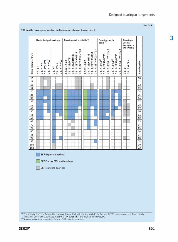
The standard assortment of SKF double row angular contact ball bearings comprises bearings in the 32 A, 33 A and 33 D series . Matrix 2 († page 501) provides an overview of the standard assortment . For information about other double row angular contact ball bearings, refer to the product information available online at skf .com/bearings .
Bearings in the 52 and 53 series, in ac cordance with ABMA standards, are no longer available from SKF and have been replaced with 32 and 33 series bearings in accordance with ISO . With the exception of size 3200, 32 and 33 series bearings are dimensionally interchangeable with bearings in the 52 and 53 series . Size 3200 has a width of 14 mm instead of 14,3 mm .
Fig. 3
Tandem Back-to-back Face-to-face arrangement arrangement arrangement
478

3
Designs and variants
Basic design bearingsBasic design bearings (designation suffix A) have an optimized internal geometry to provide high radial and axial load carrying capacity and quiet operation . Basic design bearings that are also available capped may have recesses in the inner and outer rings († fig. 5) .
Bearings with a two-piece inner ringBearings with a two-piece inner ring († fig. 6) incorporate a large number of large balls, giv-ing the bearing its high load carrying capacity, especially in the axial direction .
Bearings in the 33 D series are separable, i .e . the outer ring with ball and cage assemblies can be mounted independently of the inner ring halves .
Bearings in the 33 DNRCBM series are non-separable . They have a snap ring groove with a snap ring in the outer ring, enabling simple and space-saving axial location in the housing . Bearings in the 33 DNRCBM series have been designed specifically for centrifugal pumps, but can also be used in other applications .
Fig. 4
Fig. 5
Fig. 6
33 D 33 DNRCBM
479

3 Angular contact ball bearings
Four-point contact ball bearingsFour-point contact ball bearings († fig. 7) are radial single row angular contact ball bearings with raceways that are designed to support axial loads in both directions . For a given axial load, a limited radial load can be supported († Load ratio, page 499) . These bearings take up considerably less axial space than double row bearings .
The inner ring is split . This enables a large number of balls to be incorporated in the bear-ing, giving the bearing its high load carrying capacity . The bearings are separable, i .e . the outer ring with ball and cage assembly can be mounted separately from the two inner ring halves .
Both inner ring halves of SKF Explorer four-point contact ball bearings have a recessed shoulder . This improves oil flow when the bearing is used together with an SKF cylin-drical roller bearing († fig. 12, page 499) . In addition, these recesses can be used to facili-tate dismounting .
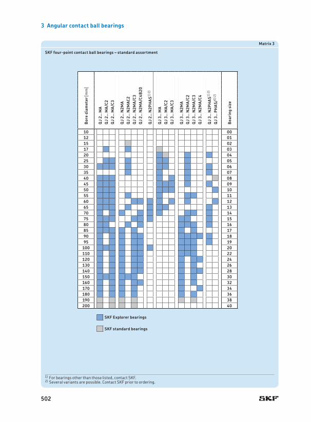
The standard assortment of SKF four-point contact ball bearings comprises bearings in the QJ 2 and QJ 3 series . Matrix 3 († page 502) provides an overview of the standard assortment . For information about other four-point contact ball bearings, refer to the product information available online at skf .com/bearings .
Fig. 7
Table 1
Cages for single row angular contact ball bearingsStandard assortment † matrix 1, page 500
Cages for double row angular contact ball bearingsStandard assortment † matrix 2, page 501
Cages for four-point contact ball bearingsStandard assortment † matrix 3, page 502
Cage type
Window-type, ball centred Window-type, ball centred
Window-type, ball centred
Snap-type, ball centred
Snap-type, ball centred
Snap-type, crown, ball centred
Window-type, ball centred
Prong-type, outer ring centred
Window-type, outer ring centred
Window-type, lubrication grooves in the guiding surface, outer ring centred
Material PA66, glass fibre reinforced
PEEK, glass fibre reinforced
Stamped brass, stamped steel1)
Machined brass, machined steel1)
PA66, glass fibre reinforced
Stamped steel
Stamped steel
Machined brass
Machined brass
Machined brass
PEEK, glass fibre reinforced
Suffix P PH Y, J1) M, F1) TN9 – – M MA MA PHAS
1) Check availability prior to ordering
480

3
Designs and variants
CagesDepending on their design, series and size, SKF angular contact ball bearings are fitted with one of the cages shown in table 1 . Double row bearings are equipped with two cages . The stamped steel cage in double row bearings is not identified in the bearing designation . For information about the availability of cages for the various bearing designs, series and sizes, refer to matrices 1 to 3 († pages 500 to 502) .
The lubricants generally used for rolling bearings do not have a detrimental effect on cage properties . However, some synthetic oils and greases with a synthetic oil base and lubricants containing a high proportion of EP additives, when used at high temperatures, can have a detrimental effect on polyamide cages . For additional information about the suitability of cages, refer to Cages († page 37) and Cage materials († page 152) .
Table 1
Cages for single row angular contact ball bearingsStandard assortment † matrix 1, page 500
Cages for double row angular contact ball bearingsStandard assortment † matrix 2, page 501
Cages for four-point contact ball bearingsStandard assortment † matrix 3, page 502
Cage type
Window-type, ball centred Window-type, ball centred
Window-type, ball centred
Snap-type, ball centred
Snap-type, ball centred
Snap-type, crown, ball centred
Window-type, ball centred
Prong-type, outer ring centred
Window-type, outer ring centred
Window-type, lubrication grooves in the guiding surface, outer ring centred
Material PA66, glass fibre reinforced
PEEK, glass fibre reinforced
Stamped brass, stamped steel1)
Machined brass, machined steel1)
PA66, glass fibre reinforced
Stamped steel
Stamped steel
Machined brass
Machined brass
Machined brass
PEEK, glass fibre reinforced
Suffix P PH Y, J1) M, F1) TN9 – – M MA MA PHAS
1) Check availability prior to ordering
481

3 Angular contact ball bearings
Sealing solutionsSKF supplies the most common basic design double row angular contact ball bearings capped with a contact seal or shield on both sides († matrix 2, page 501) . For additional information about the suitability of seals or shields under various conditions, refer to Sealing solutions († page 226) .
Bearings capped on both sides are lubricated for the life of the bearing and should not be washed or relubricated . The bearings are con-sidered maintenance-free . If they are to be hot mounted, an induction heater should be used . SKF does not recommend heating capped bearings above 80 °C (175 °F) . However, if higher temperatures are necessary make sure that the temperature does not exceed the per-missible temperature of either the seal or grease, which ever is lowest . During start-up, grease may leak at the inner ring . For bearing arrangements where this would be detrimental, special design steps must be undertaken . For additional information, contact the SKF appli-cation engineering service .
ShieldsShields are made of sheet steel . SKF supplies shields in two designs . The shields used in smaller bearings have an extension in the shield bore to form a long, narrow gap with the land of the inner ring shoulder († fig. 8a) . The shields used in larger bearings and in all SKF Explorer bearings extend into a recess on the inner ring († fig. 8b) .
Fig. 9Fig. 8
a b
SKF double row angular contact ball bear-ings with a shield on both sides are identified by the designation suffix 2Z .
Contact sealsContact seals († fig. 9) are made of NBR and are reinforced with a sheet steel insert . These seals, which are fitted in a recess on the outer ring, make good, positive contact with the recess . The seal lip exerts light pressure against the recess on the inner ring to provide an effective seal .
SKF double row angular contact ball bear-ings with a contact seal on both sides are iden-tified by the designation suffix 2RS1 .
482
3
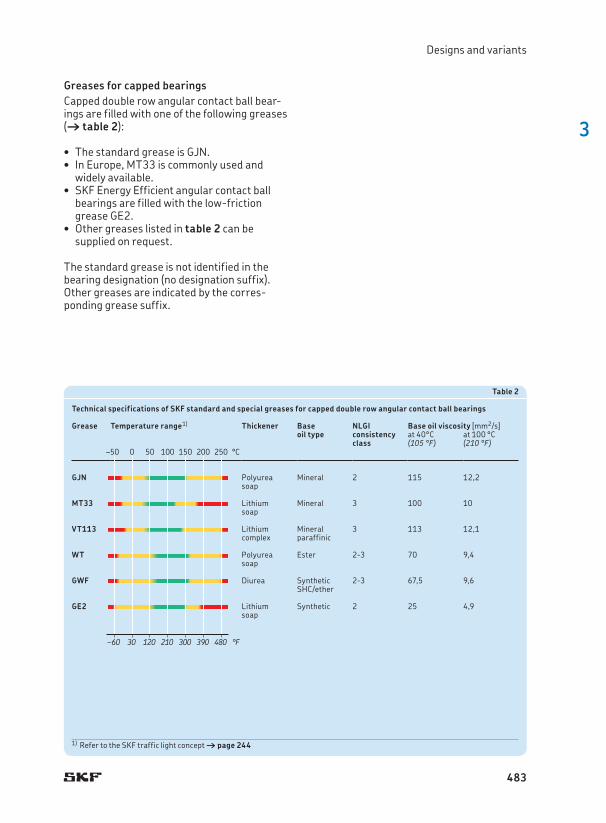
Greases for capped bearingsCapped double row angular contact ball bear-ings are filled with one of the following greases († table 2):
The standard grease is • GJN . In Europe, • MT33 is commonly used and widely available .SKF Energy Efficient angular contact ball •bearings are filled with the low-friction grease GE2 . Other greases listed in • table 2 can be supplied on request .
The standard grease is not identified in the bearing designation (no designation suffix) . Other greases are indicated by the corres-ponding grease suffix .
Designs and variants
Table 2
Technical specifications of SKF standard and special greases for capped double row angular contact ball bearings
Grease
Temperature range1)
Thickener
Base oil type
NLGI consistencyclass
Base oil viscosity [mm2/s]at 40°C at 100 °C(105 °F) (210 °F)
GJN Polyurea soap
Mineral 2 115 12,2
MT33 Lithium soap
Mineral 3 100 10
VT113 Lithium complex
Mineral paraffinic
3 113 12,1
WT Polyurea soap
Ester 2-3 70 9,4
GWF Diurea Synthetic SHC/ether
2-3 67,5 9,6
GE2 Lithium soap
Synthetic 2 25 4,9
1) Refer to the SKF traffic light concept † page 244
–50 0 50 100 150 200 250 °C
–60 30 120 210 300 390 480 °F
–50 0 50 100 150 200 250 °C
–60 30 120 210 300 390 480 °F
483

3 Angular contact ball bearings
Locating slotsSKF four-point contact ball bearings can be supplied with two locating slots in the outer ring († fig. 10) to prevent it from turning (designation suffix N2) . The locating slots are positioned 180° apart . The dimensions and tolerances of the locating slots are in accord-ance with ISO 20515 and are listed in table 3 . Some SKF single row angular contact ball bearings can be supplied with one locating slot in the outer ring (designation suffix N1) .
Fig. 10
Table 3
Locating slots in the outer ring of four-point contact ball bearings
Outside diameterD
Dimensions Diameter series 2
Diameter series 3
Tolerance1)
h b r0 h b r0 tover incl . max .
mm mm mm
35 45 2,5 3,5 0,5 – – – 0,245 60 3 4,5 0,5 3,5 4,5 0,5 0,260 72 3,5 4,5 0,5 3,5 4,5 0,5 0,2
72 95 4 5,5 0,5 4 5,5 0,5 0,295 115 5 6,5 0,5 5 6,5 0,5 0,2115 130 6,5 6,5 0,5 8,1 6,5 1 0,2
130 145 8,1 6,5 1 8,1 6,5 1 0,2145 170 8,1 6,5 1 10,1 8,5 2 0,2170 190 10,1 8,5 2 11,7 10,5 2 0,2
190 210 10,1 8,5 2 11,7 10,5 2 0,2210 240 11,7 10,5 2 11,7 10,5 2 0,2240 270 11,7 10,5 2 11,7 10,5 2 0,2270 400 12,7 10,5 2 12,7 10,5 2 0,4
45°
r0
h
b
D
A t A
1) Other tolerances are in accordance with ISO 20515 .
484

3
Performance classes
Performance classesSKF Explorer bearingsIn response to the ever-demanding perform-ance requirements of modern machinery, SKF developed the SKF Explorer performance class of rolling bearings .
SKF Explorer angular contact ball bearings realized this substantial improvement in per-formance by optimizing the internal geometry and surface finish of all contact surfaces, redesigning the cage, combining the extremely clean and homogenous steel with a unique heat treatment and improving the quality and consistency of the balls .
These improvements provide the following benefits:
higher • dynamic load carrying capacity less sensitivity to • heavy axial loads improved wear-resistance •reduced noise and vibration levels •less frictional • heat significantly longer bearing service life •
These bearings reduce environmental impact by enabling downsizing and reducing both lubricant and energy consumption . Just as importantly, SKF Explorer bearings can reduce the need for maintenance and contribute to increased productivity .
SKF Explorer bearings are shown with an asterisk in the product tables . The bearings retain the designation of earlier standard bearings . However, each bearing and its box are marked with the name “SKF Explorer” .
SKF Energy Efficient (E2) bearingsTo meet the ever-increasing demand to reduce friction and energy consumption, SKF has developed the SKF Energy Efficient (E2) per-formance class of rolling bearings . Angular contact ball bearings within this performance class are characterized by a frictional moment in the bearing that is at least 30% lower when compared to a same-sized standard SKF bearing . Due to the reduction of the frictional moment, SKF E2 double row angular contact ball bearings run up to 20 °C (35 °F) cooler than standard bearings . This extends grease life and potentially bearing service life .
The bearings realized the substantial reduction of the frictional moment by optimiz-ing the internal geometry of the bearing and applying a new, low-friction grease .
SKF E2 double row angular contact ball bearings are available in the 32 and 33 dimen-sion series († matrix 2, page 501) . The bearings are equipped with a shield on both sides and lubricated for the life of the bearing .
485

3 Angular contact ball bearings
Bearing dataSingle row angular contact ball bearings Double row angular contact ball bearings Four-point contact ball bearings
Dimension standards
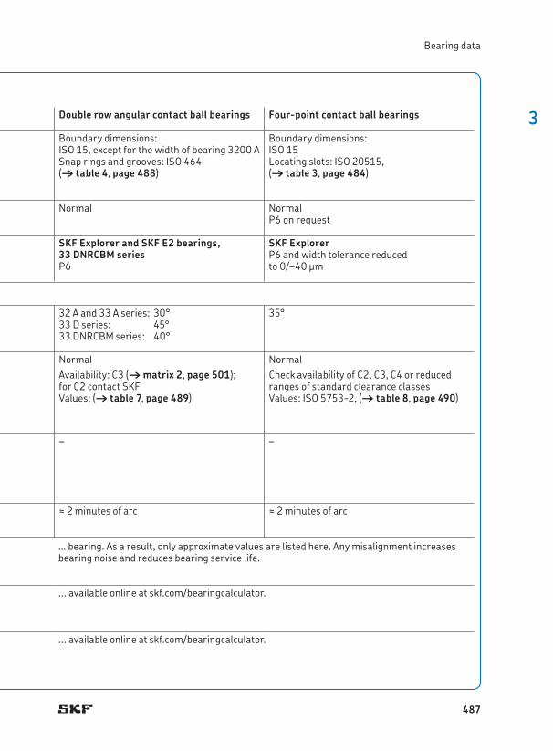
Boundary dimensions: ISO 15 and ISO 12044 Boundary dimensions: ISO 15, except for the width of bearing 3200 ASnap rings and grooves: ISO 464, († table 4, page 488)
Boundary dimensions: ISO 15Locating slots: ISO 20515, († table 3, page 484)
Tolerances
For additional information († page 132)
Normal Normal NormalP6 on request
SKF Explorer bearingsP6 dimensional accuracyP5 running accuracy
SKF Explorer and SKF E2 bearings, 33 DNRCBM seriesP6
SKF ExplorerP6 and width tolerance reduced to 0/–40 µm
Values: ISO 492, († tables 3 to 5, pages 137 to 139)
Contact angle 40°For a 25° or 30° contact angle, contact SKF .
32 A and 33 A series: 30°33 D series: 45°33 DNRCBM series: 40°
35°
Internal clearance
For additional information († page 149)
Pairs of universally matchable bearings: CB (normal), GAvailability CA and CC: († matrix 1, page 500)Values: († table 5, page 488)Values apply to unmounted bearing sets, arranged back-to-back or face-to-face under zero measuring load .
NormalAvailability: C3 († matrix 2, page 501); for C2 contact SKFValues: († table 7, page 489)
NormalCheck availability of C2, C3, C4 or reduced ranges of standard clearance classesValues: ISO 5753-2, († table 8, page 490)
Preload
For additional information († page 214)
Pairs of universally matchable bearings: GA (light preload)Availability GB and GC: († matrix 1, page 500)Values: († table 6, page 489)Values apply to unmounted bearing sets, arranged back-to-back or face-to-face .
– –
Misalignment Bearing pairs arranged back-to-back: ≈ 2 minutes of arcBearing pairs arranged face-to-face: ≈ 4 minutes of arc
≈ 2 minutes of arc ≈ 2 minutes of arc
Friction, starting torque, power loss
Defect frequencies
The permissible angular misalignment between the inner and outer rings depends on the size and internal design of the bearing, the radial internal clearance in operation and the forces and moments acting on the . . .
Frictional moment, starting torque, and power loss can be calculated as specified under Friction († page 97), or using the tools . . .
Defect frequencies can be calculated using the tools . . .
486
3
Bearing data
Bearing dataSingle row angular contact ball bearings Double row angular contact ball bearings Four-point contact ball bearings
Dimension standards
Boundary dimensions: ISO 15 and ISO 12044 Boundary dimensions: ISO 15, except for the width of bearing 3200 ASnap rings and grooves: ISO 464, († table 4, page 488)
Boundary dimensions: ISO 15Locating slots: ISO 20515, († table 3, page 484)
Tolerances
For additional information († page 132)
Normal Normal NormalP6 on request
SKF Explorer bearingsP6 dimensional accuracyP5 running accuracy
SKF Explorer and SKF E2 bearings, 33 DNRCBM seriesP6
SKF ExplorerP6 and width tolerance reduced to 0/–40 µm
Values: ISO 492, († tables 3 to 5, pages 137 to 139)
Contact angle 40°For a 25° or 30° contact angle, contact SKF .
32 A and 33 A series: 30°33 D series: 45°33 DNRCBM series: 40°
35°
Internal clearance
For additional information († page 149)
Pairs of universally matchable bearings: CB (normal), GAvailability CA and CC: († matrix 1, page 500)Values: († table 5, page 488)Values apply to unmounted bearing sets, arranged back-to-back or face-to-face under zero measuring load .
NormalAvailability: C3 († matrix 2, page 501); for C2 contact SKFValues: († table 7, page 489)
NormalCheck availability of C2, C3, C4 or reduced ranges of standard clearance classesValues: ISO 5753-2, († table 8, page 490)
Preload
For additional information († page 214)
Pairs of universally matchable bearings: GA (light preload)Availability GB and GC: († matrix 1, page 500)Values: († table 6, page 489)Values apply to unmounted bearing sets, arranged back-to-back or face-to-face .
– –
Misalignment Bearing pairs arranged back-to-back: ≈ 2 minutes of arcBearing pairs arranged face-to-face: ≈ 4 minutes of arc
≈ 2 minutes of arc ≈ 2 minutes of arc
Friction, starting torque, power loss
Defect frequencies
… bearing . As a result, only approximate values are listed here . Any misalignment increases bearing noise and reduces bearing service life .
. . . available online at skf .com/bearingcalculator .
. . . available online at skf .com/bearingcalculator .
487

3 Angular contact ball bearings
Table 4
Dimensions of snap ring grooves and snap rings
Bearing Dimensions Snap ringDesignation Designation
C b f D3 D4
– mm –
3308 DNRCBM 3,28 2,7 2,46 86,8 96,5 SP 90
3309 DNRCBM 3,28 2,7 2,46 96,8 106,5 SP 100
3310 DNRCBM 3,28 2,7 2,46 106,8 116,6 SP 110
3311 DNRCBM 4,06 3,4 2,82 115,2 129,7 SP 120
3313 DNRCBM 4,06 3,4 2,82 135,2 149,7 SP 140
fb
D3 CD4
Table 5
Axial internal clearance of universally matchable single row angular contact ball bearings arranged back-to-back or face-to-face
Borediameter
Axial internal clearance Class
d CA CB CC Gover incl . min . max . min . max . min . max . min . max .
mm µm
– 18 5 13 15 23 24 32 – –18 30 7 15 18 26 32 40 – –30 50 9 17 22 30 40 48 – –
50 80 11 23 26 38 48 60 – –80 120 14 26 32 44 55 67 – –120 160 17 29 35 47 62 74 26 76
160 180 17 29 35 47 62 74 20 72180 250 21 37 45 61 74 90 20 72250 280 – – – – – – 20 72
C
C
488

3
Bearing data
Table 7
Axial internal clearance of double row angular contact ball bearings
Borediameter
Axial internal clearance of bearings in the series 32 A and 33 A 33 D 33 DNRCBM
d C2 Normal C3 C4over incl . min . max . min . max . min . max . min . max . min . max . min . max .
mm µm µm µm
– 10 1 11 5 21 12 28 25 45 25 45 – –10 18 1 12 6 23 13 31 27 47 27 47 – –18 24 2 14 7 25 16 34 28 48 27 47 6 26
24 30 2 15 8 27 18 37 30 50 30 50 6 2630 40 2 16 9 29 21 40 33 54 33 54 10 3040 50 2 18 11 33 23 44 36 58 36 58 10 30
50 65 3 22 13 36 26 48 40 63 40 63 18 3865 80 3 24 15 40 30 54 46 71 46 71 18 3880 100 3 26 18 46 35 63 55 83 55 83 – –
100 110 4 30 22 53 42 73 65 96 65 96 – –
Table 6
Preload of universally matchable single row angular contact ball bearings arranged back-to-back or face-to-face
Borediameter
Preload Class
d GA GB GCover incl . min . max . max . min . max . min . max . min . max . min . max .
mm µm N µm N µm N
10 18 +4 –4 80 –2 –10 30 330 –8 –16 230 66018 30 +4 –4 120 –2 –10 40 480 –8 –16 340 97030 50 +4 –4 160 –2 –10 60 630 –8 –16 450 1 280
50 80 +6 –6 380 –3 –15 140 1 500 –12 –24 1 080 3 05080 120 +6 –6 410 –3 –15 150 1 600 –12 –24 1 150 3 250120 180 +6 –6 540 –3 –15 200 2 150 –12 –24 1 500 4 300
180 250 +8 –8 940 –4 –20 330 3 700 –16 –32 2 650 7 500
G
G
489
3 Angular contact ball bearings
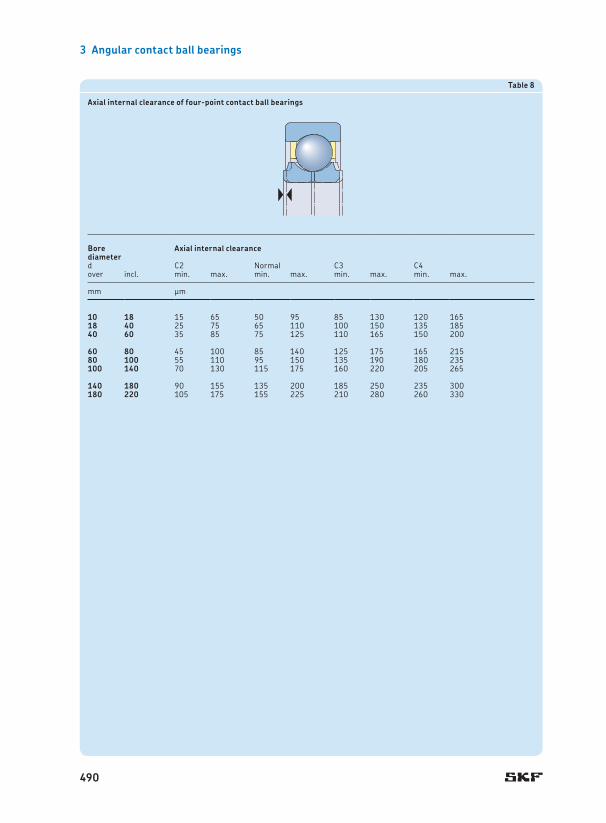
Table 8
Axial internal clearance of four-point contact ball bearings
Borediameter
Axial internal clearance
d C2 Normal C3 C4over incl . min . max . min . max . min . max . min . max .
mm µm
10 18 15 65 50 95 85 130 120 16518 40 25 75 65 110 100 150 135 18540 60 35 85 75 125 110 165 150 200
60 80 45 100 85 140 125 175 165 21580 100 55 110 95 150 135 190 180 235100 140 70 130 115 175 160 220 205 265
140 180 90 155 135 200 185 250 235 300180 220 105 175 155 225 210 280 260 330
490
3
Bearing data
491

3 Angular contact ball bearings
LoadsSingle row angular contact ball bearings
Double row angular contact ball bearings
Four-point contact ball bearings Symbols
Minimum load
For additional information († page 86)
Minimum axial load for single bearings and bearing pairs arranged in tandem:
C0 q n dm w 2Fam = ka JJJ JJJJ 1 000 < 100 000 z
– Minimum axial load:
C0 q n dm w 2Fam = ka JJJ JJJJ 1 000 < 100 000 z
C0 = basic static load rating [kN] († product tables)
dm = bearing mean diameter [mm] = 0,5 (d + D)
e = calculation factor for double row bearings († table 10, page 494)
Fa = axial load [kN]Fam = minimum axial load [kN]Fr = radial load [kN]Frm = minimum radial load [kN]ka = minimum axial load factor
(† table 9, page 494)kr = minimum radial load factor
(† table 9, page 494)n = rotational speed [r/min]P = equivalent dynamic bearing load
[kN]P0 = equivalent static bearing load [kN]X, Y0, Y1, Y2 = calculation factors for double
row bearings, depending on the bearing series († table 10, page 494)
n = oil viscosity at operating temperature [mm2/s]
Minimum radial load for bearing pairs arranged back-to-back or face-to-face:
q n n w 2/3 q dm w 2Frm = kr JJJ JJ < 1 000 z < 100 z
Minimum radial load:
q n n w 2/3 q dm w 2Frm = kr JJJ JJ < 1 000 z < 100 z
–
Equivalent dynamic bearing load
For additional information († page 85)
Single bearings and bearing pairs arranged in tandem:
Fa/Fr ≤ 1,141) † P = FrFa/Fr > 1,141) † P = 0,35 Fr + 0,57 Fa
Fa/Fr ≤ e † P = Fr + Y1 FaFa/Fr > e † P = X Fr + Y2 Fa
Locating bearings to accommodate radial and axial load:
Fa/Fr ≤ 0,952) † P = Fr + 0,66 FaFa/Fr > 0,952) † P = 0,6 Fr + 1,07 Fa
Bearing pairs arranged back-to-back or face-to-face:
Fa/Fr ≤ 1,14 † P = Fr + 0,55 FaFa/Fr > 1,14 † P = 0,57 Fr + 0,93 Fa
Thrust bearings with radial freedom in combination with a radial bearing:
P = 1,07 Fa
Equivalent static bearing load
For additional information († page 88)
Single bearings and bearing pairs arranged in tandem:
P0 = 0,5 Fr + 0,26 Fa1)
P0 < Fr † P0 = Fr
P0 = Fr + Y0 Fa P0 = Fr + 0,58 Fa
Bearing pairs arranged back-to-back or face-to-face:
P0 = Fr + 0,52 Fa
The weight of the components supported by the bearing, together with external forces, generally exceed the requisite minimum load . If this is not the case, the bearing must be subjected to an additional load . Single row bearings, bearing pairs arranged in tandem and four-point bearings can …
1) When determining the axial load Fa, refer to Calculating the axial load for bearings mounted singly or paired in tandem († page 495) .
492

3
Loads
LoadsSingle row angular contact ball bearings
Double row angular contact ball bearings
Four-point contact ball bearings Symbols
Minimum load
For additional information († page 86)
Minimum axial load for single bearings and bearing pairs arranged in tandem:
C0 q n dm w 2Fam = ka JJJ JJJJ 1 000 < 100 000 z
– Minimum axial load:
C0 q n dm w 2Fam = ka JJJ JJJJ 1 000 < 100 000 z
C0 = basic static load rating [kN] († product tables)
dm = bearing mean diameter [mm] = 0,5 (d + D)
e = calculation factor for double row bearings († table 10, page 494)
Fa = axial load [kN]Fam = minimum axial load [kN]Fr = radial load [kN]Frm = minimum radial load [kN]ka = minimum axial load factor
(† table 9, page 494)kr = minimum radial load factor
(† table 9, page 494)n = rotational speed [r/min]P = equivalent dynamic bearing load
[kN]P0 = equivalent static bearing load [kN]X, Y0, Y1, Y2 = calculation factors for double
row bearings, depending on the bearing series († table 10, page 494)
n = oil viscosity at operating temperature [mm2/s]
Minimum radial load for bearing pairs arranged back-to-back or face-to-face:
q n n w 2/3 q dm w 2Frm = kr JJJ JJ < 1 000 z < 100 z
Minimum radial load:
q n n w 2/3 q dm w 2Frm = kr JJJ JJ < 1 000 z < 100 z
–
Equivalent dynamic bearing load
For additional information († page 85)
Single bearings and bearing pairs arranged in tandem:
Fa/Fr ≤ 1,141) † P = FrFa/Fr > 1,141) † P = 0,35 Fr + 0,57 Fa
Fa/Fr ≤ e † P = Fr + Y1 FaFa/Fr > e † P = X Fr + Y2 Fa
Locating bearings to accommodate radial and axial load:
Fa/Fr ≤ 0,952) † P = Fr + 0,66 FaFa/Fr > 0,952) † P = 0,6 Fr + 1,07 Fa
Bearing pairs arranged back-to-back or face-to-face:
Fa/Fr ≤ 1,14 † P = Fr + 0,55 FaFa/Fr > 1,14 † P = 0,57 Fr + 0,93 Fa
Thrust bearings with radial freedom in combination with a radial bearing:
P = 1,07 Fa
Equivalent static bearing load
For additional information († page 88)
Single bearings and bearing pairs arranged in tandem:
P0 = 0,5 Fr + 0,26 Fa1)
P0 < Fr † P0 = Fr
P0 = Fr + Y0 Fa P0 = Fr + 0,58 Fa
Bearing pairs arranged back-to-back or face-to-face:
P0 = Fr + 0,52 Fa
… be axially preloaded by adjusting the inner or outer rings against each other or by using springs, whereas double row bearings must be subjected to an additional radial load .
1) When determining the axial load Fa, refer to Calculating the axial load for bearings mounted singly or paired in tandem († page 495) . 2) For a proper function, SKF recommends the axial load Fa ≥ 1,27 Fr .
493
3 Angular contact ball bearings
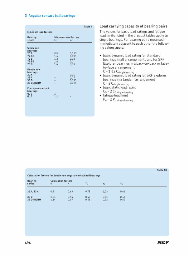
Table 9
Minimum load factors
Bearing Minimum load factorsseries ka kr
Single row bearings70 B 0,9 0,08372 BE 1,4 0,09572 B 1,2 0,0873 BE 1,6 0,173 B 1,4 0,09
Double row bearings32 A – 0,0633 A – 0,0733 D – 0,09533 DNRCBM – 0,095
Four-point contact bearingsQJ 2 1 –QJ 3 1,1 –
Table 10
Calculation factors for double row angular contact ball bearings
Bearing Calculation factorsseries e X Y1 Y2 Y0
32 A, 33 A 0,8 0,63 0,78 1,24 0,66
33 D 1,34 0,54 0,47 0,81 0,4433 DNRCBM 1,14 0,57 0,55 0,93 0,52
Load carrying capacity of bearing pairs The values for basic load ratings and fatigue load limits listed in the product tables apply to single bearings . For bearing pairs mounted immediately adjacent to each other the follow-ing values apply:
basic dynamic load rating for standard •bearings in all arrangements and for SKF Explorer bearings in a back-to-back or face-to-face arrangement C = 1,62 Csingle bearingbasic dynamic load rating for SKF Explorer •bearings in a tandem arrangement C = 2 Csingle bearingbasic static load rating •C0 = 2 C0 single bearingfatigue load limit •Pu = 2 Pu single bearing
494
3
Loads
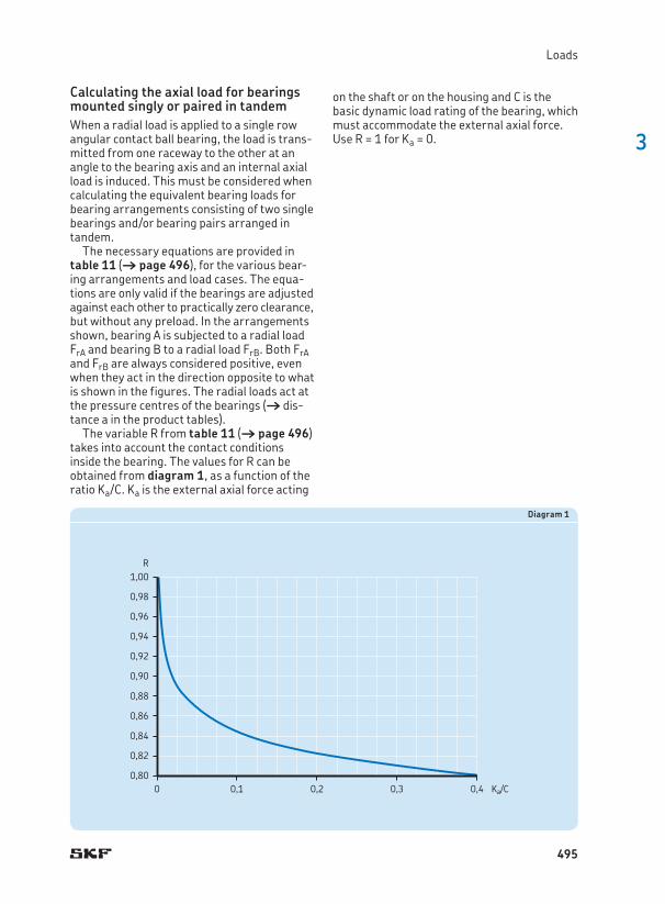
Diagram 1
1,00R
0,98
0,96
0,94
0,92
0,90
0,88
0,86
0,84
0,82
0,800 0,1 0,2 0,3 0,4 Ka/C
Calculating the axial load for bearings mounted singly or paired in tandemWhen a radial load is applied to a single row angular contact ball bearing, the load is trans-mitted from one raceway to the other at an angle to the bearing axis and an internal axial load is induced . This must be considered when calculating the equivalent bearing loads for bearing arrangements consisting of two single bearings and/or bearing pairs arranged in tandem .
The necessary equations are provided in table 11 († page 496), for the various bear-ing arrangements and load cases . The equa-tions are only valid if the bearings are adjusted against each other to practically zero clearance, but without any preload . In the arrangements shown, bearing A is subjected to a radial load FrA and bearing B to a radial load FrB . Both FrA and FrB are always considered positive, even when they act in the direction opposite to what is shown in the figures . The radial loads act at the pressure centres of the bearings († dis-tance a in the product tables) .
The variable R from table 11 († page 496) takes into account the contact conditions inside the bearing . The values for R can be obtained from diagram 1, as a function of the ratio Ka/C . Ka is the external axial force acting
on the shaft or on the housing and C is the basic dynamic load rating of the bearing, which must accommodate the external axial force . Use R = 1 for Ka = 0 .
495

3 Angular contact ball bearings
Table 11
Axial loading of bearing arrangements incorporating two single row B or BE design angular contact ball bearings and/or bearing pairs in tandem
Bearing arrangement Load case Axial loads
Back-to-back Case 1a
FrA ≥ FrB FaA = R FrA FaB = FaA + Ka
Ka ≥ 0
Case 1b
FrA < FrB FaA = R FrA FaB = FaA + Ka
Ka ≥ R (FrB – FrA)Face-to-face
Case 1c
FrA < FrB FaA = FaB – Ka FaB = R FrB
Ka < R (FrB – FrA)
Back-to-back Case 2a
FrA ≤ FrB FaA = FaB + Ka FaB = R FrB
Ka ≥ 0
Case 2b
FrA > FrB FaA = FaB + Ka FaB = R FrB
Ka ≥ R (FrA – FrB)Face-to-face
Case 2c
FrA > FrB FaA = R FrA FaB = FaA – Ka
Ka < R (FrA – FrB)
FrBFrA
B A
Ka
A B
FrAFrB
Ka
Ka
FrAFrB
A B
FrBFrA
B A
Ka
496
3
Permissible speed
Temperature limits The permissible operating temperature for angular contact ball bearings can be limited by:
the dimensional stability of the bearing •rings and ballsthe cage•the seals•the lubricant•
When temperatures outside the permissible range are expected, contact the SKF applica-tion engineering service .
Bearing rings and ballsSKF angular contact ball bearings undergo a special heat treatment . The bearings are heat stabilized up to at least 150 °C (300 °F) .
CagesSteel, brass or PEEK cages can be used at the same operating temperatures as the bearing rings and balls . For temperature limits of cages made of other polymer mater ials, refer to Cage materials († page 152) .
SealsThe permissible operating temperature for NBR seals is –40 to +100 °C (–40 to +210 °F) . Temperatures up to 120 °C (250 °F) can be tolerated for brief periods .
LubricantsTemperature limits for greases used in capped SKF angular contact ball bearings are provided in table 2 († page 483) . Temperature limits for other SKF greases are provided under Lubrication († page 239) .
When using lubricants not supplied by SKF, the temperature limits should be evaluated according to the SKF traffic light concept († page 244) .
Permissible speedThe permissible speed can be estimated using the speed ratings listed in the product tables and applying the information provided under Speeds († page 117) . If no reference speed is listed in the product tables, the limiting speed is the permissible speed .
Bearing pairsFor bearings arranged in pairs, the permissible speed calculated for a single bearing should be reduced to approximately 80% of the quoted value .
497
3 Angular contact ball bearings
Design of bearing arrangementsSingle row angular contact ball bearings
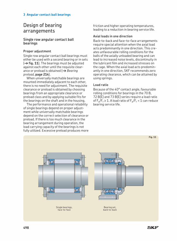
Proper adjustmentSingle row angular contact ball bearings must either be used with a second bearing or in sets († fig. 11) . The bearings must be adjusted against each other until the requisite clear-ance or preload is obtained († Bearing preload, page 214) .
When universally matchable bearings are mounted immediately adjacent to each other, there is no need for adjustment . The requisite clearance or preload is obtained by choosing bearings from an appropriate clearance or preload class and by applying suitable fits for the bearings on the shaft and in the housing .
The performance and operational reliability of single bearings depend on proper adjust-ment while universally matchable bearings depend on the correct selection of clearance or preload . If there is too much clearance in the bearing arrangement during operation, the load carrying capacity of the bearings is not fully utilized . Excessive preload produces more
friction and higher operating temperatures, leading to a reduction in bearing service life .
Axial loads in one directionBack-to-back and face-to-face arrangements require special attention when the axial load acts predominantly in one direction . This cre-ates unfavourable rolling conditions for the balls of the axially unloaded bearing and can lead to increased noise levels, discontinuity in the lubricant film and increased stresses on the cage . When the axial load acts pre dom in-antly in one direction, SKF recommends zero operating clearance, which can be attained by using springs .
Load ratioBecause of the 40° contact angle, favourable rolling conditions for bearings in the 70 B, 72 B(E) and 73 B(E) series require a load ratio of Fa/Fr ≥ 1 . A load ratio of Fa/Fr < 1 can reduce bearing service life .
Fig. 11
Single bearings, face-to-face
Bearing set, back-to-back
498
3
Design of bearing arrangements
Fig. 12
Four-point contact ball bearings
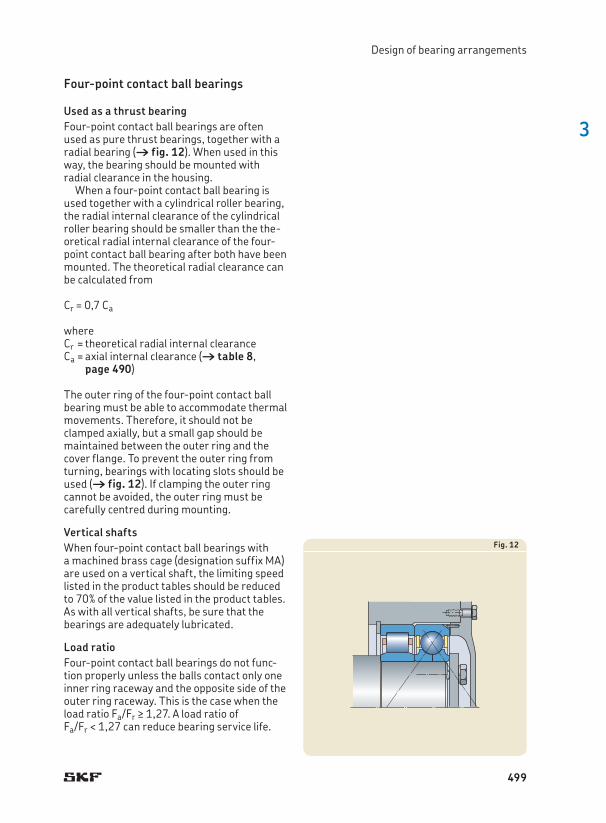
Used as a thrust bearingFour-point contact ball bearings are often used as pure thrust bearings, together with a radial bearing († fig. 12) . When used in this way, the bearing should be mounted with radial clearance in the housing .
When a four-point contact ball bearing is used together with a cylindrical roller bearing, the radial internal clearance of the cylindrical roller bearing should be smaller than the the-or eti cal radial internal clearance of the four-point contact ball bearing after both have been mounted . The theoretical radial clearance can be calculated from
Cr = 0,7 Ca
whereCr = theoretical radial internal clearanceCa = axial internal clearance († table 8,
page 490)
The outer ring of the four-point contact ball bearing must be able to accommodate thermal movements . Therefore, it should not be clamped axially, but a small gap should be maintained between the outer ring and the cover flange . To prevent the outer ring from turning, bearings with locating slots should be used († fig. 12) . If clamping the outer ring cannot be avoided, the outer ring must be carefully centred during mounting .
Vertical shaftsWhen four-point contact ball bearings with a machined brass cage (designation suffix MA) are used on a vertical shaft, the limiting speed listed in the product tables should be reduced to 70% of the value listed in the product tables . As with all vertical shafts, be sure that the bearings are adequately lubricated .
Load ratioFour-point contact ball bearings do not func-tion properly unless the balls contact only one inner ring raceway and the opposite side of the outer ring raceway . This is the case when the load ratio Fa/Fr ≥ 1,27 . A load ratio of Fa/Fr < 1,27 can reduce bearing service life .
499

3 Angular contact ball bearings
Matrix 1
SKF single row angular contact ball bearings – standard assortmentB
ore
diam
eter
[mm
]
Basic design bearings
Universally matchable bearings
Bea
ring
siz
e
70..
BG
M
72..
BEC
BP
72..
BEG
AP72
.. B
EGB
P
72..
BEG
APH
1)
72..
BEC
BP
H1)
72..
B(E
)CB
M72
.. B
ECCM
72..
B(E
)GAM
72..
BE.
.Y2)
72..
BE.
.J2)
72..
BEG
AF
73..
BEC
AP73
.. B
ECB
P73
.. B
EGAP
73..
BEG
BP
73..
BEG
APH
1)
73..
BEC
BP
H1)
73..
B(E
)CB
M73
.. B
ECCM
73..
B(E
)GAM
73..
BEG
BM
73..
BE.
.Y2)
73..
BE.
.J2)
73..
BEG
AF
72..
BEP
72..
BEM
73..
BEP
73..
BEM
73..
BEN
12)
10 0012 0115 0217 0320 0425 0530 0635 0740 0845 0950 1055 1160 1265 1370 1475 1580 1685 1790 1895 19
100 20105 21110 22120 24130 26140 28150 30160 32170 34180 36190 38200 40220 44240 48250 50260 52270 54280 56300 60320 64
SKF Explorer bearings
SKF standard bearings
1) For bearings other than those listed, contact SKF .2) Several variants are possible . Contact SKF prior to ordering .
500
3
Design of bearing arrangements
Matrix 2
SKF double row angular contact ball bearings – standard assortmentB
ore
diam
eter
[mm
]
Basic design bearings Bearings with shields1) Bearings with seals1)
Bearings with a two-piece inner ring
Bea
ring
siz
e
32..
A2)
32..
AT
N9
32..
AT
N9/
C232
.. A
TN
9/C3
33..
A2)
33..
AT
N9
33..
AT
N9/
C3
E2.3
2.. A
-2Z
32..
A-2
Z/M
T33
32..
A-2
Z/C
3MT
3332
.. A
-2ZT
N9/
MT
3332
.. A
-2ZT
N9/
C3M
T33
E2.3
3.. A
-2Z
33..
A-2
Z/C
3MT
3333
.. A
-2ZT
N9/
MT
3333
.. A
-2ZT
N9/
C3M
T33
32..
A-2
RS1
2)
32..
A-2
RS1
/MT
3332
.. A
-2R
S1T
N9/
MT
33
33..
A-2
RS1
2)
33..
A-2
RS1
/MT
3333
.. A
-2R
S1T
N9/
MT
33
33..
D33
.. D
NR
CBM
10 0012 0115 0217 0320 0425 0530 0635 0740 0845 0950 1055 1160 1265 1370 1475 1580 1685 1790 1895 19
100 20110 22
SKF Explorer bearings
SKF Energy Efficient bearings
SKF standard bearings
1) The standard grease for double row angular contact ball bearings is GJN . In Europe, MT33 is commonly used and widely available . Other greases listed in table 2 († page 483) are available on request .
2) Several variants are possible . Contact SKF prior to ordering .
501
3 Angular contact ball bearings
Matrix 3
SKF four-point contact ball bearings – standard assortment
Bor
e di
amet
er [m
m]
QJ
2.. M
AQ
J 2.
. MA
/C2
QJ
2.. M
A/C
3
QJ
2.. N
2MA
QJ
2.. N
2MAC
2Q
J 2.
. N2M
A/C
3Q
J 2.
. N2M
A/C
4B20
QJ
2.. N
2PH
AS1)
2)
QJ
3.. M
AQ
J 3.
. MA
/C2
QJ
3.. M
A/C
3
QJ
3.. N
2MA
QJ
3.. N
2MA
/C2
QJ
3.. N
2MA
/C3
QJ
3.. N
2MA
/C4
QJ
3.. N
2PH
AS1)
2)
QJ
3.. P
HA
S/1)
2)
Bea
ring
siz
e
10 0012 0115 0217 0320 0425 0530 0635 0740 0845 0950 1055 1160 1265 1370 1475 1580 1685 1790 1895 19
100 20110 22120 24130 26140 28150 30160 32170 34180 36190 38200 40
SKF Explorer bearings
SKF standard bearings
1) For bearings other than those listed, contact SKF .2) Several variants are possible . Contact SKF prior to ordering .
502

3
Design of bearing arrangements
503

3 Angular contact ball bearings
Designation system
Prefixes
E2. SKF Energy Efficient bearing
Basic designation
Listed in diagram 2 († page 43)
Suffixes
Group 1: Internal design
A Single row bearing with a 30° contact angleA Double row bearing without filling slotsAC Single row bearing with a 25° contact angleB Single row bearing with a 40° contact angleD Two-piece inner ringE Optimized internal design
Group 2: External design (seals, snap ring groove etc.)
N Snap ring groove in the outer ringNR Snap ring groove in the outer ring, with appropriate snap ringN1 One locating slot (notch) in one outer ring side faceN2 Two locating slots (notches) in one outer ring side face, 180° apart-2RS1 Contact seal, NBR, on both sides-2Z Shield on both sides
Group 3: Cage design
F Machined steel cage, ball centredFA Machined steel cage, outer ring centredJ Stamped steel cage, ball centredM Machined brass cage, ball centred; different designs for single row bearings are
identified by a number following the M, e .g . M2MA Machined brass cage, outer ring centredP Single row bearing with a glass fibre reinforced PA66 cage, ball centredPH Glass fibre reinforced PEEK cage, ball centredPHAS Glass fibre reinforced PEEK cage, with lubrication grooves in the guiding surface,
outer ring centredTN9 Glass fibre reinforced PA66 cage, ball centredY Stamped brass cage, ball centred
Group 4.6: Other variants
Group 4.5: Lubrication
GWFMT33 Grease suffixes († table 2, page 483)VT113WT
Group 4.4: Stabilization
S1 Bearing rings heat stabilized for operating temperatures ≤ 200 °C (390 °F)
Group 4.3: Bearing sets, matched bearings
DB Two bearings matched for mounting back-to-backDF Two bearings matched for mounting face-to-faceDT Two bearings matched for mounting in tandem
Group 4.2: Accuracy, clearance, preload, quiet running
B20 Reduced width toleranceP5 Dimensional and running accuracy to P5 tolerance classP6 Dimensional and running accuracy to P6 tolerance classP62 P6 + C2P63 P6 + C3P64 P6 + C4CNL Axial internal clearance in the lower half of the Normal rangeC2 Axial internal clearance smaller than NormalC2H Axial internal clearance in the upper half of the C2 rangeC2L Axial internal clearance in the lower half of the C2 rangeC3 Axial internal clearance greater than NormalC4 Axial internal clearance greater than C3CB Double row bearing with controlled axial clearanceCA Bearing for universal matching . Two bearings arranged back-to-back or
face-to-face have axial internal clearance smaller than Normal (CB) .CB Bearing for universal matching . Two bearings arranged back-to-back or
face-to-face have Normal axial internal clearance .CC Bearing for universal matching . Two bearings arranged back-to-back or
face-to-face have axial internal clearance greater than Normal (CB) .G Bearing for universal matching . Two bearings arranged back-to-back or
face-to-face have axial internal clearance .GA Bearing for universal matching . Two bearings arranged back-to-back or
face-to-face have light preload .GB Bearing for universal matching . Two bearings arranged back-to-back or
face-to-face have moderate preload .GC Bearing for universal matching . Two bearings arranged back-to-back or
face-to-face have heavy preload .
Group 4.1: Materials, heat treatment
Group 1 Group 2 Group 3 / Group 4
4 .1 4 .2 4 .3 4 .4 4 .5 4 .6
504

3
Designation system
Designation system
Prefixes
E2. SKF Energy Efficient bearing
Basic designation
Listed in diagram 2 († page 43)
Suffixes
Group 1: Internal design
A Single row bearing with a 30° contact angleA Double row bearing without filling slotsAC Single row bearing with a 25° contact angleB Single row bearing with a 40° contact angleD Two-piece inner ringE Optimized internal design
Group 2: External design (seals, snap ring groove etc.)
N Snap ring groove in the outer ringNR Snap ring groove in the outer ring, with appropriate snap ringN1 One locating slot (notch) in one outer ring side faceN2 Two locating slots (notches) in one outer ring side face, 180° apart-2RS1 Contact seal, NBR, on both sides-2Z Shield on both sides
Group 3: Cage design
F Machined steel cage, ball centredFA Machined steel cage, outer ring centredJ Stamped steel cage, ball centredM Machined brass cage, ball centred; different designs for single row bearings are
identified by a number following the M, e .g . M2MA Machined brass cage, outer ring centredP Single row bearing with a glass fibre reinforced PA66 cage, ball centredPH Glass fibre reinforced PEEK cage, ball centredPHAS Glass fibre reinforced PEEK cage, with lubrication grooves in the guiding surface,
outer ring centredTN9 Glass fibre reinforced PA66 cage, ball centredY Stamped brass cage, ball centred
Group 4.6: Other variants
Group 4.5: Lubrication
GWFMT33 Grease suffixes († table 2, page 483)VT113WT
Group 4.4: Stabilization
S1 Bearing rings heat stabilized for operating temperatures ≤ 200 °C (390 °F)
Group 4.3: Bearing sets, matched bearings
DB Two bearings matched for mounting back-to-backDF Two bearings matched for mounting face-to-faceDT Two bearings matched for mounting in tandem
Group 4.2: Accuracy, clearance, preload, quiet running
B20 Reduced width toleranceP5 Dimensional and running accuracy to P5 tolerance classP6 Dimensional and running accuracy to P6 tolerance classP62 P6 + C2P63 P6 + C3P64 P6 + C4CNL Axial internal clearance in the lower half of the Normal rangeC2 Axial internal clearance smaller than NormalC2H Axial internal clearance in the upper half of the C2 rangeC2L Axial internal clearance in the lower half of the C2 rangeC3 Axial internal clearance greater than NormalC4 Axial internal clearance greater than C3CB Double row bearing with controlled axial clearanceCA Bearing for universal matching . Two bearings arranged back-to-back or
face-to-face have axial internal clearance smaller than Normal (CB) .CB Bearing for universal matching . Two bearings arranged back-to-back or
face-to-face have Normal axial internal clearance .CC Bearing for universal matching . Two bearings arranged back-to-back or
face-to-face have axial internal clearance greater than Normal (CB) .G Bearing for universal matching . Two bearings arranged back-to-back or
face-to-face have axial internal clearance .GA Bearing for universal matching . Two bearings arranged back-to-back or
face-to-face have light preload .GB Bearing for universal matching . Two bearings arranged back-to-back or
face-to-face have moderate preload .GC Bearing for universal matching . Two bearings arranged back-to-back or
face-to-face have heavy preload .
Group 4.1: Materials, heat treatment
Group 1 Group 2 Group 3 / Group 4
4 .1 4 .2 4 .3 4 .4 4 .5 4 .6
rfc
505

10 30 9 7,02 3,35 0,14 30 000 30 000 0,03 7200 BECBP 7200 BEP 10 18,3 14,6 22,9 0,6 0,3 13 14,2 25,8 27,6 0,6 0,3
12 32 10 7,61 3,8 0,16 26 000 26 000 0,036 7201 BECBP 7201 BEP 12 20,2 16,6 25 0,6 0,3 14 16,2 27,8 30 0,6 0,337 12 10,6 5 0,208 24 000 24 000 0,06 – 7301 BEP 21,8 17 28,3 1 0,6 16,3 17,6 31,4 32,8 1 0,6
15 35 11 8,8 4,65 0,196 26 000 26 000 0,045 * 7202 BECBP – 15 22,7 19 27,8 0,6 0,3 16 19,2 30,8 32,6 0,6 0,335 11 8,32 4,4 0,183 24 000 24 000 0,045 – 7202 BEP 22,7 19 27,8 0,6 0,3 16 19,2 30,8 32,6 0,6 0,342 13 13 6,7 0,28 20 000 20 000 0,08 7302 BECBP 7302 BEP 26 20,7 32,6 1 0,6 18,6 20,6 36 38 1 0,6
17 40 12 11 5,85 0,25 22 000 22 000 0,065 * 7203 BECBM – 17 26,3 21,7 31,2 0,6 0,6 18 21,2 35,8 35,8 0,6 0,640 12 11 5,85 0,25 22 000 22 000 0,065 * 7203 BECBP – 26,3 21,7 31,2 0,6 0,6 18 21,2 35,8 35,8 0,6 0,640 12 10,4 5,5 0,236 20 000 20 000 0,065 – 7203 BEP 26,3 21,7 31,2 0,6 0,6 18 21,2 35,8 35,8 0,6 0,640 12 11,1 6,1 0,26 20 000 20 000 0,065 – 7203 BEY 26,3 21,7 31,2 0,6 0,6 18 21,2 35,8 35,8 0,6 0,647 14 15,9 8,3 0,355 19 000 19 000 0,11 7303 BECBP 7303 BEP 28,7 22,8 36,2 1 0,6 20,4 22,6 41,4 42,8 1 0,6
20 47 14 14,3 8,15 0,345 19 000 19 000 0,11 * 7204 BECBM – 20 30,8 25,9 36,5 1 0,6 21 25,6 41,4 42,8 1 0,647 14 14,3 8,15 0,345 19 000 19 000 0,11 * 7204 BECBP – 30,8 25,9 36,5 1 0,6 21 25,6 41,4 42,8 1 0,647 14 14 8,3 0,355 18 000 18 000 0,11 7204 BECBY – 30,8 25,9 36,5 1 0,6 21 25,6 41,4 42,8 1 0,647 14 13,3 7,65 0,325 18 000 18 000 0,11 – 7204 BEP 30,8 25,9 36,5 1 0,6 21 25,6 41,4 42,8 1 0,647 14 14,3 8,15 0,345 19 000 19 000 0,11 * 7204 BECBPH – 30,8 25,9 36,5 1 0,6 21 25,6 41,4 42,8 1 0,6
52 15 19 10 0,425 18 000 18 000 0,14 * 7304 BECBPH – 33,3 33,3 40,4 1,1 0,6 22,8 27 45 47,8 1 0,652 15 19 10 0,425 18 000 18 000 0,14 * 7304 BECBM – 33,3 33,3 40,4 1,1 0,6 22,8 27 45 47,8 1 0,652 15 19 10 0,425 18 000 18 000 0,14 * 7304 BECBP – 33,3 33,3 40,4 1,1 0,6 22,8 27 45 47,8 1 0,652 15 19 10,4 0,44 16 000 16 000 0,14 7304 BECBY – 33,3 33,3 40,4 1,1 0,6 22,8 27 45 47,8 1 0,652 15 17,4 9,5 0,4 16 000 16 000 0,14 – 7304 BEP 33,3 33,3 40,4 1,1 0,6 22,8 27 45 47,8 1 0,6
25 52 15 15,6 10 0,43 17 000 17 000 0,13 * 7205 BECBPH – 25 36,1 30,9 41,5 1 0,6 24 30,6 46,4 47,8 1 0,652 15 15,6 10 0,43 17 000 17 000 0,13 * 7205 BECBM – 36,1 30,9 41,5 1 0,6 24 30,6 46,4 47,8 1 0,652 15 15,6 10 0,43 17 000 17 000 0,13 * 7205 BECBP – 36,1 30,9 41,5 1 0,6 24 30,6 46,4 47,8 1 0,652 15 15,6 10,2 0,43 15 000 15 000 0,13 7205 BECBY 7205 BEY 36,1 30,9 41,5 1 0,6 24 30,6 46,4 47,8 1 0,652 15 14,8 9,3 0,4 15 000 15 000 0,13 – 7205 BEP 36,1 30,9 41,5 1 0,6 24 30,6 46,4 47,8 1 0,6
62 17 26,5 15,3 0,655 15 000 15 000 0,23 * 7305 BECBPH – 39,8 32,4 48,1 1,1 0,6 26,8 32 55 57,8 1 0,662 17 26,5 15,3 0,655 15 000 15 000 0,23 * 7305 BECBM – 39,8 32,4 48,1 1,1 0,6 26,8 32 55 57,8 1 0,662 17 26,5 15,3 0,655 15 000 15 000 0,23 * 7305 BECBP – 39,8 32,4 48,1 1,1 0,6 26,8 32 55 57,8 1 0,662 17 26 15,6 0,655 14 000 14 000 0,23 7305 BECBY 7305 BEY 39,8 32,4 48,1 1,1 0,6 26,8 32 55 57,8 1 0,662 17 24,2 14 0,6 14 000 14 000 0,23 – 7305 BEP 39,8 32,4 48,1 1,1 0,6 26,8 32 55 57,8 1 0,6
a
D1D
B
d d1
r2r3
r4
r1r2
r1r2
r1
d2
3.1 Single row angular contact ball bearingsd 10–25 mm
Principal dimensions Basic load ratings Fatigue load
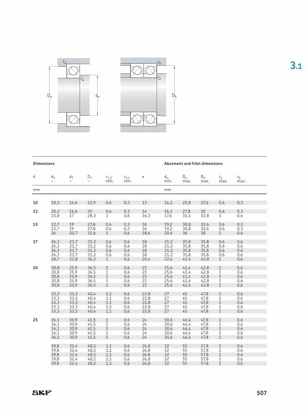
limitSpeed ratings Mass Designations1) Dimensions Abutment and fillet dimensions
dynamic static Reference speed
Limiting speed
Universally matchable bearing
Basic design bearing
d D B C C0 Pu d d1 d2 D1 r1,2 r3,4 a da Da Db ra rb~ ~ ~ min . min . min . max . max . max . max .
mm kN kN r/min kg – mm mm
1) For available final variants † matrix 1, page 500SKF Explorer bearing *
506
10 30 9 7,02 3,35 0,14 30 000 30 000 0,03 7200 BECBP 7200 BEP 10 18,3 14,6 22,9 0,6 0,3 13 14,2 25,8 27,6 0,6 0,3
12 32 10 7,61 3,8 0,16 26 000 26 000 0,036 7201 BECBP 7201 BEP 12 20,2 16,6 25 0,6 0,3 14 16,2 27,8 30 0,6 0,337 12 10,6 5 0,208 24 000 24 000 0,06 – 7301 BEP 21,8 17 28,3 1 0,6 16,3 17,6 31,4 32,8 1 0,6
15 35 11 8,8 4,65 0,196 26 000 26 000 0,045 * 7202 BECBP – 15 22,7 19 27,8 0,6 0,3 16 19,2 30,8 32,6 0,6 0,335 11 8,32 4,4 0,183 24 000 24 000 0,045 – 7202 BEP 22,7 19 27,8 0,6 0,3 16 19,2 30,8 32,6 0,6 0,342 13 13 6,7 0,28 20 000 20 000 0,08 7302 BECBP 7302 BEP 26 20,7 32,6 1 0,6 18,6 20,6 36 38 1 0,6
17 40 12 11 5,85 0,25 22 000 22 000 0,065 * 7203 BECBM – 17 26,3 21,7 31,2 0,6 0,6 18 21,2 35,8 35,8 0,6 0,640 12 11 5,85 0,25 22 000 22 000 0,065 * 7203 BECBP – 26,3 21,7 31,2 0,6 0,6 18 21,2 35,8 35,8 0,6 0,640 12 10,4 5,5 0,236 20 000 20 000 0,065 – 7203 BEP 26,3 21,7 31,2 0,6 0,6 18 21,2 35,8 35,8 0,6 0,640 12 11,1 6,1 0,26 20 000 20 000 0,065 – 7203 BEY 26,3 21,7 31,2 0,6 0,6 18 21,2 35,8 35,8 0,6 0,647 14 15,9 8,3 0,355 19 000 19 000 0,11 7303 BECBP 7303 BEP 28,7 22,8 36,2 1 0,6 20,4 22,6 41,4 42,8 1 0,6
20 47 14 14,3 8,15 0,345 19 000 19 000 0,11 * 7204 BECBM – 20 30,8 25,9 36,5 1 0,6 21 25,6 41,4 42,8 1 0,647 14 14,3 8,15 0,345 19 000 19 000 0,11 * 7204 BECBP – 30,8 25,9 36,5 1 0,6 21 25,6 41,4 42,8 1 0,647 14 14 8,3 0,355 18 000 18 000 0,11 7204 BECBY – 30,8 25,9 36,5 1 0,6 21 25,6 41,4 42,8 1 0,647 14 13,3 7,65 0,325 18 000 18 000 0,11 – 7204 BEP 30,8 25,9 36,5 1 0,6 21 25,6 41,4 42,8 1 0,647 14 14,3 8,15 0,345 19 000 19 000 0,11 * 7204 BECBPH – 30,8 25,9 36,5 1 0,6 21 25,6 41,4 42,8 1 0,6
52 15 19 10 0,425 18 000 18 000 0,14 * 7304 BECBPH – 33,3 33,3 40,4 1,1 0,6 22,8 27 45 47,8 1 0,652 15 19 10 0,425 18 000 18 000 0,14 * 7304 BECBM – 33,3 33,3 40,4 1,1 0,6 22,8 27 45 47,8 1 0,652 15 19 10 0,425 18 000 18 000 0,14 * 7304 BECBP – 33,3 33,3 40,4 1,1 0,6 22,8 27 45 47,8 1 0,652 15 19 10,4 0,44 16 000 16 000 0,14 7304 BECBY – 33,3 33,3 40,4 1,1 0,6 22,8 27 45 47,8 1 0,652 15 17,4 9,5 0,4 16 000 16 000 0,14 – 7304 BEP 33,3 33,3 40,4 1,1 0,6 22,8 27 45 47,8 1 0,6
25 52 15 15,6 10 0,43 17 000 17 000 0,13 * 7205 BECBPH – 25 36,1 30,9 41,5 1 0,6 24 30,6 46,4 47,8 1 0,652 15 15,6 10 0,43 17 000 17 000 0,13 * 7205 BECBM – 36,1 30,9 41,5 1 0,6 24 30,6 46,4 47,8 1 0,652 15 15,6 10 0,43 17 000 17 000 0,13 * 7205 BECBP – 36,1 30,9 41,5 1 0,6 24 30,6 46,4 47,8 1 0,652 15 15,6 10,2 0,43 15 000 15 000 0,13 7205 BECBY 7205 BEY 36,1 30,9 41,5 1 0,6 24 30,6 46,4 47,8 1 0,652 15 14,8 9,3 0,4 15 000 15 000 0,13 – 7205 BEP 36,1 30,9 41,5 1 0,6 24 30,6 46,4 47,8 1 0,6
62 17 26,5 15,3 0,655 15 000 15 000 0,23 * 7305 BECBPH – 39,8 32,4 48,1 1,1 0,6 26,8 32 55 57,8 1 0,662 17 26,5 15,3 0,655 15 000 15 000 0,23 * 7305 BECBM – 39,8 32,4 48,1 1,1 0,6 26,8 32 55 57,8 1 0,662 17 26,5 15,3 0,655 15 000 15 000 0,23 * 7305 BECBP – 39,8 32,4 48,1 1,1 0,6 26,8 32 55 57,8 1 0,662 17 26 15,6 0,655 14 000 14 000 0,23 7305 BECBY 7305 BEY 39,8 32,4 48,1 1,1 0,6 26,8 32 55 57,8 1 0,662 17 24,2 14 0,6 14 000 14 000 0,23 – 7305 BEP 39,8 32,4 48,1 1,1 0,6 26,8 32 55 57,8 1 0,6
3.1
Db
ra
rb
daDa
ra
ra
Principal dimensions Basic load ratings Fatigue load
limitSpeed ratings Mass Designations1) Dimensions Abutment and fillet dimensions
dynamic static Reference speed
Limiting speed
Universally matchable bearing
Basic design bearing
d D B C C0 Pu d d1 d2 D1 r1,2 r3,4 a da Da Db ra rb~ ~ ~ min . min . min . max . max . max . max .
mm kN kN r/min kg – mm mm
507
30 62 16 24 15,6 0,655 14 000 14 000 0,2 * 7206 BECBM – 30 42,7 36,1 50,1 1 0,6 27,3 35,6 56,4 57,8 1 0,662 16 24 15,6 0,655 14 000 14 000 0,2 * 7206 BECBP – 42,7 36,1 50,1 1 0,6 27,3 35,6 56,4 57,8 1 0,662 16 23,8 15,6 0,655 13 000 13 000 0,2 7206 BECBY – 42,7 36,1 50,1 1 0,6 27,3 35,6 56,4 57,8 1 0,662 16 22,5 14,3 0,61 13 000 13 000 0,2 – 7206 BEP 42,7 36,1 50,1 1 0,6 27,3 35,6 56,4 57,8 1 0,662 16 24 15,6 0,655 14 000 14 000 0,2 * 7206 BECBPH – 42,7 36,1 50,1 1 0,6 27,3 35,6 56,4 57,8 1 0,6
72 19 35,5 21,2 0,9 13 000 13 000 0,34 * 7306 BECBM – 46,6 37,9 56,5 1,1 0,6 31 37 65 67,8 1 0,672 19 35,5 21,2 0,9 13 000 13 000 0,34 * 7306 BECBP – 46,6 37,9 56,5 1,1 0,6 31 37 65 67,8 1 0,672 19 34,5 21,2 0,9 12 000 12 000 0,34 7306 BECBY – 46,6 37,9 56,5 1,1 0,6 31 37 65 67,8 1 0,672 19 32,5 19,3 0,815 12 000 12 000 0,34 – 7306 BEP 46,6 37,9 56,5 1,1 0,6 31 37 65 67,8 1 0,672 19 35,5 21,2 0,9 13 000 13 000 0,34 * 7306 BEGAPH – 46,6 37,9 56,5 1,1 0,6 31 37 65 67,8 1 0,6
35 72 17 31 20,8 0,88 12 000 12 000 0,28 * 7207 BECBPH – 35 49,7 42 58,3 1,1 0,6 31 42 65 67,8 1 0,672 17 31 20,8 0,88 12 000 12 000 0,28 * 7207 BECBM – 49,7 42 58,3 1,1 0,6 31 42 65 67,8 1 0,672 17 31 20,8 0,88 12 000 12 000 0,28 * 7207 BECBP – 49,7 42 58,3 1,1 0,6 31 42 65 67,8 1 0,672 17 29,1 19 0,815 11 000 11 000 0,28 7207 BECBY 7207 BEP 49,7 42 58,3 1,1 0,6 31 42 65 67,8 1 0,6
80 21 41,5 26,5 1,14 11 000 11 000 0,45 * 7307 BECBM – 52,8 43,6 63,3 1,5 1 35 44 71 74,4 1,5 180 21 41,5 26,5 1,14 11 000 11 000 0,45 * 7307 BECBP – 52,8 43,6 63,3 1,5 1 35 44 71 74,4 1,5 180 21 39 24,5 1,04 10 000 10 000 0,45 7307 BECBY 7307 BEP 52,8 43,6 63,3 1,5 1 35 44 71 74,4 1,5 180 21 41,5 26,5 1,14 11 000 11 000 0,45 * 7307 BEGAPH – 52,8 43,6 63,3 1,5 1 35 44 71 74,4 1,5 1
40 80 18 36,5 26 1,1 11 000 11 000 0,37 * 7208 BECBPH – 40 56,3 48,1 65,6 1,1 0,6 34 47 73 75,8 1 0,680 18 36,5 26 1,1 11 000 11 000 0,37 * 7208 BECBM – 56,3 48,1 65,6 1,1 0,6 34 47 73 75,8 1 0,680 18 36,5 26 1,1 11 000 11 000 0,37 * 7208 BECBP – 56,3 48,1 65,6 1,1 0,6 34 47 73 75,8 1 0,680 18 36,4 26 1,1 10 000 10 000 0,37 7208 BECBY – 56,3 48,1 65,6 1,1 0,6 34 47 73 75,8 1 0,680 18 37,7 26 1,1 11 000 11 000 0,37 – 7208 BEP 56,3 48,1 65,6 1,1 0,6 34 47 73 75,8 1 0,6
90 23 50 32,5 1,37 10 000 10 000 0,68 * 7308 BECBM – 59,7 49,6 71,6 1,5 1 39 49 81 84,4 1,5 190 23 50 32,5 1,37 10 000 10 000 0,62 * 7308 BECBP – 59,7 49,6 71,6 1,5 1 39 49 81 84,4 1,5 190 23 49,4 33,5 1,4 9 000 9 000 0,64 7308 BECBY – 59,7 49,6 71,6 1,5 1 39 49 81 84,4 1,5 190 23 46,2 30,5 1,29 9 000 9 000 0,62 – 7308 BEP 59,7 49,6 71,6 1,5 1 39 49 81 84,4 1,5 190 23 50 32,5 1,37 10 000 10 000 0,62 * 7308 BEGAPH – 59,7 49,6 71,6 1,5 1 39 49 81 84,4 1,5 1
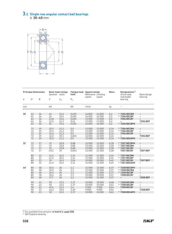
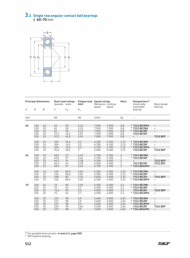
3.1 Single row angular contact ball bearingsd 30–40 mm
a
D1D
B
d d1
r2r3
r4
r1r2
r1r2
r1
d2
1) For available final variants † matrix 1, page 500SKF Explorer bearing *
Principal dimensions Basic load ratings Fatigue load
limitSpeed ratings Mass Designations1) Dimensions Abutment and fillet dimensions
dynamic static Reference speed
Limiting speed
Universally matchable bearing
Basic design bearing
d D B C C0 Pu d d1 d2 D1 r1,2 r3,4 a da Da Db ra rb~ ~ ~ min . min . min . max . max . max . max .
mm kN kN r/min kg – mm mm
508

30 62 16 24 15,6 0,655 14 000 14 000 0,2 * 7206 BECBM – 30 42,7 36,1 50,1 1 0,6 27,3 35,6 56,4 57,8 1 0,662 16 24 15,6 0,655 14 000 14 000 0,2 * 7206 BECBP – 42,7 36,1 50,1 1 0,6 27,3 35,6 56,4 57,8 1 0,662 16 23,8 15,6 0,655 13 000 13 000 0,2 7206 BECBY – 42,7 36,1 50,1 1 0,6 27,3 35,6 56,4 57,8 1 0,662 16 22,5 14,3 0,61 13 000 13 000 0,2 – 7206 BEP 42,7 36,1 50,1 1 0,6 27,3 35,6 56,4 57,8 1 0,662 16 24 15,6 0,655 14 000 14 000 0,2 * 7206 BECBPH – 42,7 36,1 50,1 1 0,6 27,3 35,6 56,4 57,8 1 0,6
72 19 35,5 21,2 0,9 13 000 13 000 0,34 * 7306 BECBM – 46,6 37,9 56,5 1,1 0,6 31 37 65 67,8 1 0,672 19 35,5 21,2 0,9 13 000 13 000 0,34 * 7306 BECBP – 46,6 37,9 56,5 1,1 0,6 31 37 65 67,8 1 0,672 19 34,5 21,2 0,9 12 000 12 000 0,34 7306 BECBY – 46,6 37,9 56,5 1,1 0,6 31 37 65 67,8 1 0,672 19 32,5 19,3 0,815 12 000 12 000 0,34 – 7306 BEP 46,6 37,9 56,5 1,1 0,6 31 37 65 67,8 1 0,672 19 35,5 21,2 0,9 13 000 13 000 0,34 * 7306 BEGAPH – 46,6 37,9 56,5 1,1 0,6 31 37 65 67,8 1 0,6
35 72 17 31 20,8 0,88 12 000 12 000 0,28 * 7207 BECBPH – 35 49,7 42 58,3 1,1 0,6 31 42 65 67,8 1 0,672 17 31 20,8 0,88 12 000 12 000 0,28 * 7207 BECBM – 49,7 42 58,3 1,1 0,6 31 42 65 67,8 1 0,672 17 31 20,8 0,88 12 000 12 000 0,28 * 7207 BECBP – 49,7 42 58,3 1,1 0,6 31 42 65 67,8 1 0,672 17 29,1 19 0,815 11 000 11 000 0,28 7207 BECBY 7207 BEP 49,7 42 58,3 1,1 0,6 31 42 65 67,8 1 0,6
80 21 41,5 26,5 1,14 11 000 11 000 0,45 * 7307 BECBM – 52,8 43,6 63,3 1,5 1 35 44 71 74,4 1,5 180 21 41,5 26,5 1,14 11 000 11 000 0,45 * 7307 BECBP – 52,8 43,6 63,3 1,5 1 35 44 71 74,4 1,5 180 21 39 24,5 1,04 10 000 10 000 0,45 7307 BECBY 7307 BEP 52,8 43,6 63,3 1,5 1 35 44 71 74,4 1,5 180 21 41,5 26,5 1,14 11 000 11 000 0,45 * 7307 BEGAPH – 52,8 43,6 63,3 1,5 1 35 44 71 74,4 1,5 1
40 80 18 36,5 26 1,1 11 000 11 000 0,37 * 7208 BECBPH – 40 56,3 48,1 65,6 1,1 0,6 34 47 73 75,8 1 0,680 18 36,5 26 1,1 11 000 11 000 0,37 * 7208 BECBM – 56,3 48,1 65,6 1,1 0,6 34 47 73 75,8 1 0,680 18 36,5 26 1,1 11 000 11 000 0,37 * 7208 BECBP – 56,3 48,1 65,6 1,1 0,6 34 47 73 75,8 1 0,680 18 36,4 26 1,1 10 000 10 000 0,37 7208 BECBY – 56,3 48,1 65,6 1,1 0,6 34 47 73 75,8 1 0,680 18 37,7 26 1,1 11 000 11 000 0,37 – 7208 BEP 56,3 48,1 65,6 1,1 0,6 34 47 73 75,8 1 0,6
90 23 50 32,5 1,37 10 000 10 000 0,68 * 7308 BECBM – 59,7 49,6 71,6 1,5 1 39 49 81 84,4 1,5 190 23 50 32,5 1,37 10 000 10 000 0,62 * 7308 BECBP – 59,7 49,6 71,6 1,5 1 39 49 81 84,4 1,5 190 23 49,4 33,5 1,4 9 000 9 000 0,64 7308 BECBY – 59,7 49,6 71,6 1,5 1 39 49 81 84,4 1,5 190 23 46,2 30,5 1,29 9 000 9 000 0,62 – 7308 BEP 59,7 49,6 71,6 1,5 1 39 49 81 84,4 1,5 190 23 50 32,5 1,37 10 000 10 000 0,62 * 7308 BEGAPH – 59,7 49,6 71,6 1,5 1 39 49 81 84,4 1,5 1
3.1
Db
ra
rb
daDa
ra
ra
Principal dimensions Basic load ratings Fatigue load
limitSpeed ratings Mass Designations1) Dimensions Abutment and fillet dimensions
dynamic static Reference speed
Limiting speed
Universally matchable bearing
Basic design bearing
d D B C C0 Pu d d1 d2 D1 r1,2 r3,4 a da Da Db ra rb~ ~ ~ min . min . min . max . max . max . max .
mm kN kN r/min kg – mm mm
509
45 85 19 38 28,5 1,22 10 000 10 000 0,42 * 7209 BECBM – 45 60,9 52,7 70,2 1,1 0,6 37 52 78 80,8 1 0,685 19 38 28,5 1,22 10 000 10 000 0,42 * 7209 BECBP – 60,9 52,7 70,2 1,1 0,6 37 52 78 80,8 1 0,685 19 37,7 28 1,2 9 000 9 000 0,42 7209 BECBY – 60,9 52,7 70,2 1,1 0,6 37 52 78 80,8 1 0,685 19 35,8 26 1,12 9 000 9 000 0,42 – 7209 BEP 60,9 52,7 70,2 1,1 0,6 37 52 78 80,8 1 0,685 19 38 28,5 1,22 10 000 10 000 0,42 * 7209 BEGAPH – 60,9 52,7 70,2 1,1 0,6 37 52 78 80,8 1 0,6
100 25 61 40,5 1,73 9 000 9 000 0,91 * 7309 BECBM – 66,5 55,3 79,8 1,5 1 43 54 91 94,4 1,5 1100 25 61 40,5 1,73 9 000 9 000 0,82 * 7309 BECBP – 66,5 55,3 79,8 1,5 1 43 54 91 94,4 1,5 1100 25 60,5 41,5 1,73 8 000 8 000 0,87 7309 BECBY – 66,5 55,3 79,8 1,5 1 43 54 91 94,4 1,5 1100 25 55,9 37,5 1,6 8 000 8 000 0,82 – 7309 BEP 66,5 55,3 79,8 1,5 1 43 54 91 94,4 1,5 1100 25 61 40,5 1,73 9 000 9 000 0,82 * 7309 BEGAPH – 66,5 55,3 79,8 1,5 1 43 54 91 94,4 1,5 1
50 90 20 40 31 1,32 9 000 9 000 0,47 * 7210 BECBPH – 50 65,8 57,7 75,2 1,1 0,6 39 57 83 85,8 1 0,690 20 40 31 1,32 9 000 9 000 0,47 * 7210 BECBM – 65,8 57,7 75,2 1,1 0,6 39 57 83 85,8 1 0,690 20 40 31 1,32 9 000 9 000 0,47 * 7210 BECBP – 65,8 57,7 75,2 1,1 0,6 39 57 83 85,8 1 0,690 20 37,7 28,5 1,22 8 500 8 500 0,47 7210 BECBY 7210 BEP 65,8 57,7 75,2 1,1 0,6 39 57 83 85,8 1 0,6
110 27 75 51 2,16 8 000 8 000 1,1 * 7310 BECBM – 73,8 61,1 88,8 2 1 47 61 99 104 2 1110 27 75 51 2,16 8 000 8 000 1,1 * 7310 BECBP – 73,8 61,1 88,8 2 1 47 61 99 104 2 1110 27 74,1 51 2,2 7 500 7 500 1,15 7310 BECBY – 73,8 61,1 88,8 2 1 47 61 99 104 2 1110 27 68,9 47,5 2 7 500 7 500 1,1 – 7310 BEP 73,8 61,1 88,8 2 1 47 61 99 104 2 1110 27 75 51 2,16 8 000 8 000 1,1 * 7310 BEGAPH – 73,8 61,1 88,8 2 1 47 61 99 104 2 1
55 100 21 49 40 1,66 8 000 8 000 0,62 * 7211 BECBPH – 55 72,7 63,6 83,3 1,5 1 43 64 91 94 1,5 1100 21 49 40 1,66 8 000 8 000 0,62 * 7211 BECBM – 72,7 63,6 83,3 1,5 1 43 64 91 94 1,5 1100 21 49 40 1,66 8 000 8 000 0,62 * 7211 BECBP – 72,7 63,6 83,3 1,5 1 43 64 91 94 1,5 1100 21 48,8 38 1,63 7 500 7 500 0,62 7211 BECBY – 72,7 63,6 83,3 1,5 1 43 64 91 94 1,5 1100 21 46,2 36 1,53 7 500 7 500 0,62 – 7211 BEP 72,7 63,6 83,3 1,5 1 43 64 91 94 1,5 1
120 29 85 60 2,55 7 000 7 000 1,4 * 7311 BECBM – 80,3 66,7 96,6 2 1 51 66 109 114 2 1120 29 85 60 2,55 7 000 7 000 1,4 * 7311 BECBP – 80,3 66,7 96,6 2 1 51 66 109 114 2 1120 29 85,2 60 2,55 6 700 6 700 1,4 7311 BECBY – 80,3 66,7 96,6 2 1 51 66 109 114 2 1120 29 79,3 55 2,32 6 700 6 700 1,4 – 7311 BEP 80,3 66,7 96,6 2 1 51 66 109 114 2 1120 29 85 60 2,55 7 000 7 000 1,4 * 7311 BECBPH – 80,3 66,7 96,6 2 1 51 66 109 114 2 1
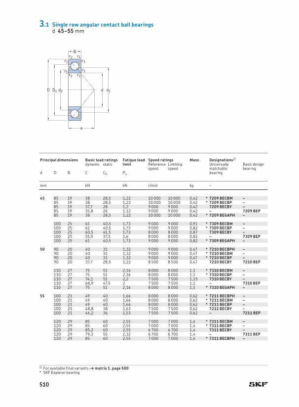
3.1 Single row angular contact ball bearingsd 45–55 mm
a
D1D
B
d d1
r2r3
r4
r1r2
r1r2
r1
d2
1) For available final variants † matrix 1, page 500SKF Explorer bearing *
Principal dimensions Basic load ratings Fatigue load
limitSpeed ratings Mass Designations1) Dimensions Abutment and fillet dimensions
dynamic static Reference speed
Limiting speed
Universally matchable bearing
Basic design bearing
d D B C C0 Pu d d1 d2 D1 r1,2 r3,4 a da Da Db ra rb~ ~ ~ min . min . min . max . max . max . max .
mm kN kN r/min kg – mm mm
510

45 85 19 38 28,5 1,22 10 000 10 000 0,42 * 7209 BECBM – 45 60,9 52,7 70,2 1,1 0,6 37 52 78 80,8 1 0,685 19 38 28,5 1,22 10 000 10 000 0,42 * 7209 BECBP – 60,9 52,7 70,2 1,1 0,6 37 52 78 80,8 1 0,685 19 37,7 28 1,2 9 000 9 000 0,42 7209 BECBY – 60,9 52,7 70,2 1,1 0,6 37 52 78 80,8 1 0,685 19 35,8 26 1,12 9 000 9 000 0,42 – 7209 BEP 60,9 52,7 70,2 1,1 0,6 37 52 78 80,8 1 0,685 19 38 28,5 1,22 10 000 10 000 0,42 * 7209 BEGAPH – 60,9 52,7 70,2 1,1 0,6 37 52 78 80,8 1 0,6
100 25 61 40,5 1,73 9 000 9 000 0,91 * 7309 BECBM – 66,5 55,3 79,8 1,5 1 43 54 91 94,4 1,5 1100 25 61 40,5 1,73 9 000 9 000 0,82 * 7309 BECBP – 66,5 55,3 79,8 1,5 1 43 54 91 94,4 1,5 1100 25 60,5 41,5 1,73 8 000 8 000 0,87 7309 BECBY – 66,5 55,3 79,8 1,5 1 43 54 91 94,4 1,5 1100 25 55,9 37,5 1,6 8 000 8 000 0,82 – 7309 BEP 66,5 55,3 79,8 1,5 1 43 54 91 94,4 1,5 1100 25 61 40,5 1,73 9 000 9 000 0,82 * 7309 BEGAPH – 66,5 55,3 79,8 1,5 1 43 54 91 94,4 1,5 1
50 90 20 40 31 1,32 9 000 9 000 0,47 * 7210 BECBPH – 50 65,8 57,7 75,2 1,1 0,6 39 57 83 85,8 1 0,690 20 40 31 1,32 9 000 9 000 0,47 * 7210 BECBM – 65,8 57,7 75,2 1,1 0,6 39 57 83 85,8 1 0,690 20 40 31 1,32 9 000 9 000 0,47 * 7210 BECBP – 65,8 57,7 75,2 1,1 0,6 39 57 83 85,8 1 0,690 20 37,7 28,5 1,22 8 500 8 500 0,47 7210 BECBY 7210 BEP 65,8 57,7 75,2 1,1 0,6 39 57 83 85,8 1 0,6
110 27 75 51 2,16 8 000 8 000 1,1 * 7310 BECBM – 73,8 61,1 88,8 2 1 47 61 99 104 2 1110 27 75 51 2,16 8 000 8 000 1,1 * 7310 BECBP – 73,8 61,1 88,8 2 1 47 61 99 104 2 1110 27 74,1 51 2,2 7 500 7 500 1,15 7310 BECBY – 73,8 61,1 88,8 2 1 47 61 99 104 2 1110 27 68,9 47,5 2 7 500 7 500 1,1 – 7310 BEP 73,8 61,1 88,8 2 1 47 61 99 104 2 1110 27 75 51 2,16 8 000 8 000 1,1 * 7310 BEGAPH – 73,8 61,1 88,8 2 1 47 61 99 104 2 1
55 100 21 49 40 1,66 8 000 8 000 0,62 * 7211 BECBPH – 55 72,7 63,6 83,3 1,5 1 43 64 91 94 1,5 1100 21 49 40 1,66 8 000 8 000 0,62 * 7211 BECBM – 72,7 63,6 83,3 1,5 1 43 64 91 94 1,5 1100 21 49 40 1,66 8 000 8 000 0,62 * 7211 BECBP – 72,7 63,6 83,3 1,5 1 43 64 91 94 1,5 1100 21 48,8 38 1,63 7 500 7 500 0,62 7211 BECBY – 72,7 63,6 83,3 1,5 1 43 64 91 94 1,5 1100 21 46,2 36 1,53 7 500 7 500 0,62 – 7211 BEP 72,7 63,6 83,3 1,5 1 43 64 91 94 1,5 1
120 29 85 60 2,55 7 000 7 000 1,4 * 7311 BECBM – 80,3 66,7 96,6 2 1 51 66 109 114 2 1120 29 85 60 2,55 7 000 7 000 1,4 * 7311 BECBP – 80,3 66,7 96,6 2 1 51 66 109 114 2 1120 29 85,2 60 2,55 6 700 6 700 1,4 7311 BECBY – 80,3 66,7 96,6 2 1 51 66 109 114 2 1120 29 79,3 55 2,32 6 700 6 700 1,4 – 7311 BEP 80,3 66,7 96,6 2 1 51 66 109 114 2 1120 29 85 60 2,55 7 000 7 000 1,4 * 7311 BECBPH – 80,3 66,7 96,6 2 1 51 66 109 114 2 1
3.1
Db
ra
rb
daDa
ra
ra
Principal dimensions Basic load ratings Fatigue load
limitSpeed ratings Mass Designations1) Dimensions Abutment and fillet dimensions
dynamic static Reference speed
Limiting speed
Universally matchable bearing
Basic design bearing
d D B C C0 Pu d d1 d2 D1 r1,2 r3,4 a da Da Db ra rb~ ~ ~ min . min . min . max . max . max . max .
mm kN kN r/min kg – mm mm
511
60 110 22 61 50 2,12 7 500 7 500 0,8 * 7212 BECBPH – 60 79,6 69,3 91,6 1,5 1 47 69 101 104 1,5 1110 22 61 50 2,12 7 500 7 500 0,8 * 7212 BECBM – 79,6 69,3 91,6 1,5 1 47 69 101 104 1,5 1110 22 61 50 2,12 7 500 7 500 0,8 * 7212 BECBP – 79,6 69,3 91,6 1,5 1 47 69 101 104 1,5 1110 22 57,2 45,5 1,93 7 000 7 000 0,8 7212 BECBY 79,6 69,3 91,6 1,5 1 47 69 101 104 1,5 1110 22 57,2 45,5 1,93 7 000 7 000 0,8 – 7212 BEP 79,6 69,3 91,6 1,5 1 47 69 101 104 1,5 1
130 31 104 76,5 3,2 6 700 6 700 1,75 * 7312 BECBM – 87,3 72,6 105 2,1 1,1 55 72 118 123 2 1130 31 104 76,5 3,2 6 700 6 700 1,75 * 7312 BECBP – 87,3 72,6 105 2,1 1,1 55 72 118 123 2 1130 31 104 76,5 3,2 6 700 6 700 1,75 * 7312 BECBPH – 87,3 72,6 105 2,1 1,1 55 72 118 123 2 1130 31 95,6 69,5 3 6 000 6 000 1,75 7312 BECBY 7312 BEP 87,3 72,6 105 2,1 1,1 55 72 118 123 2 1
65 120 23 69,5 57 2,45 6 700 6 700 1 * 7213 BECBM – 65 86,4 75,5 100 1,5 1 50 74 111 114 1,5 1120 23 69,5 57 2,45 6 700 6 700 1 * 7213 BECBP – 86,4 75,5 100 1,5 1 50 74 111 114 1,5 1120 23 66,3 54 2,28 6 300 6 300 1 – 7213 BEP 86,4 75,5 100 1,5 1 50 74 111 114 1,5 1120 23 66,3 54 2,28 6 300 6 300 1 7213 BECBY 7213 BEY 86,4 75,5 100 1,5 1 50 74 111 114 1,5 1120 23 69,5 57 2,45 6 700 6 700 1 * 7213 BEGAPH – 86,4 75,5 100 1,5 1 50 74 111 114 1,5 1
140 33 116 86,5 3,65 6 300 6 300 2,15 * 7313 BECBM – 94,2 78,5 113 2,1 1,1 60 77 128 133 2 1140 33 116 86,5 3,65 6 300 6 300 2,15 * 7313 BECBP – 94,2 78,5 113 2,1 1,1 60 77 128 133 2 1140 33 108 80 3,35 5 600 5 600 2,15 7313 BECBY 7313 BEP 94,2 78,5 113 2,1 1,1 60 77 128 133 2 1140 33 116 86,5 3,65 6 300 6 300 2,15 * 7313 BECBPH – 94,2 78,5 113 2,1 1,1 60 77 128 133 2 1
70 125 24 72 60 2,55 6 300 6 300 1,1 * 7214 BECBM – 70 91,5 80,3 105 1,5 1 53 79 116 119 1,5 1125 24 75 64 2,7 6 300 6 300 1,1 * 7214 BECBP – 91,5 80,3 105 1,5 1 53 79 116 119 1,5 1125 24 71,5 60 2,5 6 000 6 000 1,1 7214 BECBY 7214 BEP 91,5 80,3 105 1,5 1 53 79 116 119 1,5 1125 24 75 64 2,7 6 300 6 300 1,1 * 7214 BECBPH – 91,5 80,3 105 1,5 1 53 79 116 119 1,5 1
150 35 127 98 3,9 5 600 5 600 2,65 * 7314 BECBM – 101 84,4 121 2,1 1,1 64 82 138 143 2 1150 35 127 98 3,9 5 600 5 600 2,65 * 7314 BECBP – 101 84,4 121 2,1 1,1 64 82 138 143 2 1150 35 127 98 3,9 5 600 5 600 2,65 * 7314 BECBPH – 101 84,4 121 2,1 1,1 64 82 138 143 2 1150 35 119 90 3,65 5 300 5 300 2,65 7314 BECBY 7314 BEP 101 84,4 121 2,1 1,1 64 82 138 143 2 1150 35 127 98 3,9 5 600 5 600 2,65 * 7314 BEGAPH – 101 84,4 121 2,1 1,1 64 82 138 143 2 1
3.1 Single row angular contact ball bearingsd 60–70 mm
a
D1D
B
d d1
r2r3
r4
r1r2
r1r2
r1
d2
1) For available final variants † matrix 1, page 500SKF Explorer bearing *
Principal dimensions Basic load ratings Fatigue load
limitSpeed ratings Mass Designations1) Dimensions Abutment and fillet dimensions
dynamic static Reference speed
Limiting speed
Universally matchable bearing
Basic design bearing
d D B C C0 Pu d d1 d2 D1 r1,2 r3,4 a da Da Db ra rb~ ~ ~ min . min . min . max . max . max . max .
mm kN kN r/min kg – mm mm
512
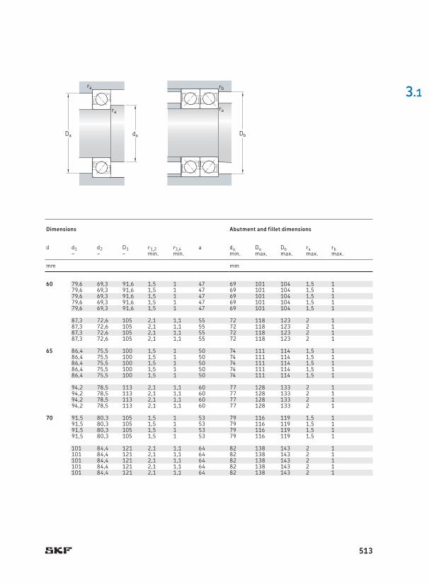
60 110 22 61 50 2,12 7 500 7 500 0,8 * 7212 BECBPH – 60 79,6 69,3 91,6 1,5 1 47 69 101 104 1,5 1110 22 61 50 2,12 7 500 7 500 0,8 * 7212 BECBM – 79,6 69,3 91,6 1,5 1 47 69 101 104 1,5 1110 22 61 50 2,12 7 500 7 500 0,8 * 7212 BECBP – 79,6 69,3 91,6 1,5 1 47 69 101 104 1,5 1110 22 57,2 45,5 1,93 7 000 7 000 0,8 7212 BECBY 79,6 69,3 91,6 1,5 1 47 69 101 104 1,5 1110 22 57,2 45,5 1,93 7 000 7 000 0,8 – 7212 BEP 79,6 69,3 91,6 1,5 1 47 69 101 104 1,5 1
130 31 104 76,5 3,2 6 700 6 700 1,75 * 7312 BECBM – 87,3 72,6 105 2,1 1,1 55 72 118 123 2 1130 31 104 76,5 3,2 6 700 6 700 1,75 * 7312 BECBP – 87,3 72,6 105 2,1 1,1 55 72 118 123 2 1130 31 104 76,5 3,2 6 700 6 700 1,75 * 7312 BECBPH – 87,3 72,6 105 2,1 1,1 55 72 118 123 2 1130 31 95,6 69,5 3 6 000 6 000 1,75 7312 BECBY 7312 BEP 87,3 72,6 105 2,1 1,1 55 72 118 123 2 1
65 120 23 69,5 57 2,45 6 700 6 700 1 * 7213 BECBM – 65 86,4 75,5 100 1,5 1 50 74 111 114 1,5 1120 23 69,5 57 2,45 6 700 6 700 1 * 7213 BECBP – 86,4 75,5 100 1,5 1 50 74 111 114 1,5 1120 23 66,3 54 2,28 6 300 6 300 1 – 7213 BEP 86,4 75,5 100 1,5 1 50 74 111 114 1,5 1120 23 66,3 54 2,28 6 300 6 300 1 7213 BECBY 7213 BEY 86,4 75,5 100 1,5 1 50 74 111 114 1,5 1120 23 69,5 57 2,45 6 700 6 700 1 * 7213 BEGAPH – 86,4 75,5 100 1,5 1 50 74 111 114 1,5 1
140 33 116 86,5 3,65 6 300 6 300 2,15 * 7313 BECBM – 94,2 78,5 113 2,1 1,1 60 77 128 133 2 1140 33 116 86,5 3,65 6 300 6 300 2,15 * 7313 BECBP – 94,2 78,5 113 2,1 1,1 60 77 128 133 2 1140 33 108 80 3,35 5 600 5 600 2,15 7313 BECBY 7313 BEP 94,2 78,5 113 2,1 1,1 60 77 128 133 2 1140 33 116 86,5 3,65 6 300 6 300 2,15 * 7313 BECBPH – 94,2 78,5 113 2,1 1,1 60 77 128 133 2 1
70 125 24 72 60 2,55 6 300 6 300 1,1 * 7214 BECBM – 70 91,5 80,3 105 1,5 1 53 79 116 119 1,5 1125 24 75 64 2,7 6 300 6 300 1,1 * 7214 BECBP – 91,5 80,3 105 1,5 1 53 79 116 119 1,5 1125 24 71,5 60 2,5 6 000 6 000 1,1 7214 BECBY 7214 BEP 91,5 80,3 105 1,5 1 53 79 116 119 1,5 1125 24 75 64 2,7 6 300 6 300 1,1 * 7214 BECBPH – 91,5 80,3 105 1,5 1 53 79 116 119 1,5 1
150 35 127 98 3,9 5 600 5 600 2,65 * 7314 BECBM – 101 84,4 121 2,1 1,1 64 82 138 143 2 1150 35 127 98 3,9 5 600 5 600 2,65 * 7314 BECBP – 101 84,4 121 2,1 1,1 64 82 138 143 2 1150 35 127 98 3,9 5 600 5 600 2,65 * 7314 BECBPH – 101 84,4 121 2,1 1,1 64 82 138 143 2 1150 35 119 90 3,65 5 300 5 300 2,65 7314 BECBY 7314 BEP 101 84,4 121 2,1 1,1 64 82 138 143 2 1150 35 127 98 3,9 5 600 5 600 2,65 * 7314 BEGAPH – 101 84,4 121 2,1 1,1 64 82 138 143 2 1
3.1
Db
ra
rb
daDa
ra
ra
Principal dimensions Basic load ratings Fatigue load
limitSpeed ratings Mass Designations1) Dimensions Abutment and fillet dimensions
dynamic static Reference speed
Limiting speed
Universally matchable bearing
Basic design bearing
d D B C C0 Pu d d1 d2 D1 r1,2 r3,4 a da Da Db ra rb~ ~ ~ min . min . min . max . max . max . max .
mm kN kN r/min kg – mm mm
513
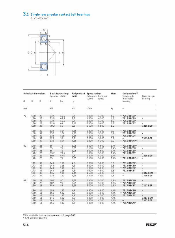
75 130 25 73,5 65,5 2,7 6 300 6 300 1,2 * 7215 BECBPH – 75 96,3 85,3 111 1,5 1 56 84 121 124 1,5 1130 25 73,5 65,5 2,7 6 300 6 300 1,2 * 7215 BECBM – 96,3 85,3 111 1,5 1 56 84 121 124 1,5 1130 25 73,5 65,5 2,7 6 300 6 300 1,2 * 7215 BECBP – 96,3 85,3 111 1,5 1 56 84 121 124 1,5 1130 25 72,8 64 2,65 5 600 5 600 1,2 7215 BECBY – 96,3 85,3 111 1,5 1 56 84 121 124 1,5 1130 25 70,2 60 2,5 5 600 5 600 1,2 – 7215 BEP 96,3 85,3 111 1,5 1 56 84 121 124 1,5 1
160 37 132 104 4,15 5 300 5 300 3,2 * 7315 BECBM – 108 91,1 129 2,1 1,1 68 87 148 153 2 1160 37 132 104 4,15 5 300 5 300 3,2 * 7315 BECBP – 108 91,1 129 2,1 1,1 68 87 148 153 2 1160 37 133 106 4,15 5 000 5 000 3,2 7315 BECBY – 108 91,1 129 2,1 1,1 68 87 148 153 2 1160 37 125 98 3,8 5 000 5 000 3,2 – 7315 BEP 108 91,1 129 2,1 1,1 68 87 148 153 2 1160 37 132 104 4,15 5 300 5 300 3,2 * 7315 BEGAPH – 108 91,1 129 2,1 1,1 68 87 148 153 2 1
80 140 26 85 75 3,05 5 600 5 600 1,45 * 7216 BECBPH – 80 103 91,4 118 2 1 59 91 130 134 2 1140 26 85 75 3,05 5 600 5 600 1,45 * 7216 BECBM – 103 91,4 118 2 1 59 91 130 134 2 1140 26 85 75 3,05 5 600 5 600 1,45 * 7216 BECBP – 103 91,4 118 2 1 59 91 130 134 2 1140 26 83,2 73,5 3 5 300 5 300 1,45 7216 BECBY – 103 91,4 118 2 1 59 91 130 134 2 1140 26 80,6 69,5 2,8 5 300 5 300 1,45 – 7216 BEP 103 91,4 118 2 1 59 91 130 134 2 1140 26 85 75 3,05 5 600 5 600 1,45 * 7216 BEGAPH – 103 91,4 118 2 1 59 91 130 134 2 1
170 39 143 118 4,5 5 000 5 000 3,8 * 7316 BECBPH – 115 97,1 137 2,1 1,1 72 92 158 163 2 1170 39 143 118 4,5 5 000 5 000 3,8 * 7316 BECBM – 115 97,1 137 2,1 1,1 72 92 158 163 2 1170 39 143 118 4,5 5 000 5 000 3,8 * 7316 BECBP – 115 97,1 137 2,1 1,1 72 92 158 163 2 1170 39 143 118 4,5 4 500 4 500 3,8 7316 BECBY – 115 97,1 137 2,1 1,1 72 92 158 163 2 1170 39 135 110 4,15 4 500 4 800 3,8 – 7316 BEM 115 97,1 137 2,1 1,1 72 92 158 163 2 1170 39 135 110 4,15 4 500 4 500 3,8 – 7316 BEP 115 97,1 137 2,1 1,1 72 92 158 163 2 1
85 150 28 102 90 3,55 5 300 5 300 1,85 * 7217 BECBM – 85 110 97 127 2 1 63 96 139 144 2 1150 28 102 90 3,55 5 300 5 300 1,85 * 7217 BECBP – 110 97 127 2 1 63 96 139 144 2 1150 28 95,6 83 3,25 5 000 5 000 1,85 7217 BECBY 7217 BEP 110 97 127 2 1 63 96 139 144 2 1
180 41 156 132 4,9 4 800 4 800 4,45 * 7317 BECBM – 122 103 145 3 1,1 76 99 166 173 2,5 1180 41 156 132 4,9 4 800 4 800 4,45 * 7317 BECBP – 122 103 145 3 1,1 76 99 166 173 2,5 1180 41 153 132 4,9 4 300 4 300 4,45 7317 BECBY – 122 103 145 3 1,1 76 99 166 173 2,5 1180 41 146 122 4,5 4 300 4 500 4,45 – 7317 BEM 122 103 145 3 1,1 76 99 166 173 2,5 1180 41 146 122 4,5 4 300 4 300 4,45 – 7317 BEP 122 103 145 3 1,1 76 99 166 173 2,5 1180 41 156 132 4,9 4 800 4 800 4,45 * 7317 BEGAPH – 122 103 145 3 1,1 76 99 166 173 2,5 1
3.1 Single row angular contact ball bearingsd 75–85 mm
a
D1D
B
d d1
r2r3
r4
r1r2
r1r2
r1
d2
1) For available final variants † matrix 1, page 500SKF Explorer bearing *
Principal dimensions Basic load ratings Fatigue load
limitSpeed ratings Mass Designations1) Dimensions Abutment and fillet dimensions
dynamic static Reference speed
Limiting speed
Universally matchable bearing
Basic design bearing
d D B C C0 Pu d d1 d2 D1 r1,2 r3,4 a da Da Db ra rb~ ~ ~ min . min . min . max . max . max . max .
mm kN kN r/min kg – mm mm
514

75 130 25 73,5 65,5 2,7 6 300 6 300 1,2 * 7215 BECBPH – 75 96,3 85,3 111 1,5 1 56 84 121 124 1,5 1130 25 73,5 65,5 2,7 6 300 6 300 1,2 * 7215 BECBM – 96,3 85,3 111 1,5 1 56 84 121 124 1,5 1130 25 73,5 65,5 2,7 6 300 6 300 1,2 * 7215 BECBP – 96,3 85,3 111 1,5 1 56 84 121 124 1,5 1130 25 72,8 64 2,65 5 600 5 600 1,2 7215 BECBY – 96,3 85,3 111 1,5 1 56 84 121 124 1,5 1130 25 70,2 60 2,5 5 600 5 600 1,2 – 7215 BEP 96,3 85,3 111 1,5 1 56 84 121 124 1,5 1
160 37 132 104 4,15 5 300 5 300 3,2 * 7315 BECBM – 108 91,1 129 2,1 1,1 68 87 148 153 2 1160 37 132 104 4,15 5 300 5 300 3,2 * 7315 BECBP – 108 91,1 129 2,1 1,1 68 87 148 153 2 1160 37 133 106 4,15 5 000 5 000 3,2 7315 BECBY – 108 91,1 129 2,1 1,1 68 87 148 153 2 1160 37 125 98 3,8 5 000 5 000 3,2 – 7315 BEP 108 91,1 129 2,1 1,1 68 87 148 153 2 1160 37 132 104 4,15 5 300 5 300 3,2 * 7315 BEGAPH – 108 91,1 129 2,1 1,1 68 87 148 153 2 1
80 140 26 85 75 3,05 5 600 5 600 1,45 * 7216 BECBPH – 80 103 91,4 118 2 1 59 91 130 134 2 1140 26 85 75 3,05 5 600 5 600 1,45 * 7216 BECBM – 103 91,4 118 2 1 59 91 130 134 2 1140 26 85 75 3,05 5 600 5 600 1,45 * 7216 BECBP – 103 91,4 118 2 1 59 91 130 134 2 1140 26 83,2 73,5 3 5 300 5 300 1,45 7216 BECBY – 103 91,4 118 2 1 59 91 130 134 2 1140 26 80,6 69,5 2,8 5 300 5 300 1,45 – 7216 BEP 103 91,4 118 2 1 59 91 130 134 2 1140 26 85 75 3,05 5 600 5 600 1,45 * 7216 BEGAPH – 103 91,4 118 2 1 59 91 130 134 2 1
170 39 143 118 4,5 5 000 5 000 3,8 * 7316 BECBPH – 115 97,1 137 2,1 1,1 72 92 158 163 2 1170 39 143 118 4,5 5 000 5 000 3,8 * 7316 BECBM – 115 97,1 137 2,1 1,1 72 92 158 163 2 1170 39 143 118 4,5 5 000 5 000 3,8 * 7316 BECBP – 115 97,1 137 2,1 1,1 72 92 158 163 2 1170 39 143 118 4,5 4 500 4 500 3,8 7316 BECBY – 115 97,1 137 2,1 1,1 72 92 158 163 2 1170 39 135 110 4,15 4 500 4 800 3,8 – 7316 BEM 115 97,1 137 2,1 1,1 72 92 158 163 2 1170 39 135 110 4,15 4 500 4 500 3,8 – 7316 BEP 115 97,1 137 2,1 1,1 72 92 158 163 2 1
85 150 28 102 90 3,55 5 300 5 300 1,85 * 7217 BECBM – 85 110 97 127 2 1 63 96 139 144 2 1150 28 102 90 3,55 5 300 5 300 1,85 * 7217 BECBP – 110 97 127 2 1 63 96 139 144 2 1150 28 95,6 83 3,25 5 000 5 000 1,85 7217 BECBY 7217 BEP 110 97 127 2 1 63 96 139 144 2 1
180 41 156 132 4,9 4 800 4 800 4,45 * 7317 BECBM – 122 103 145 3 1,1 76 99 166 173 2,5 1180 41 156 132 4,9 4 800 4 800 4,45 * 7317 BECBP – 122 103 145 3 1,1 76 99 166 173 2,5 1180 41 153 132 4,9 4 300 4 300 4,45 7317 BECBY – 122 103 145 3 1,1 76 99 166 173 2,5 1180 41 146 122 4,5 4 300 4 500 4,45 – 7317 BEM 122 103 145 3 1,1 76 99 166 173 2,5 1180 41 146 122 4,5 4 300 4 300 4,45 – 7317 BEP 122 103 145 3 1,1 76 99 166 173 2,5 1180 41 156 132 4,9 4 800 4 800 4,45 * 7317 BEGAPH – 122 103 145 3 1,1 76 99 166 173 2,5 1
3.1
Db
ra
rb
daDa
ra
ra
Principal dimensions Basic load ratings Fatigue load
limitSpeed ratings Mass Designations1) Dimensions Abutment and fillet dimensions
dynamic static Reference speed
Limiting speed
Universally matchable bearing
Basic design bearing
d D B C C0 Pu d d1 d2 D1 r1,2 r3,4 a da Da Db ra rb~ ~ ~ min . min . min . max . max . max . max .
mm kN kN r/min kg – mm mm
515

90 160 30 116 104 4 5 000 5 000 2,3 * 7218 BECBM – 90 117 103 135 2 1 67 101 149 154 2 1160 30 116 104 4 5 000 5 000 2,3 * 7218 BECBP – 117 103 135 2 1 67 101 149 154 2 1160 30 108 96,5 3,65 4 500 4 500 2,3 7218 BECBY 7218 BEP 117 103 135 2 1 67 101 149 154 2 1
190 43 166 146 5,3 4 500 4 500 5,2 * 7318 BEGAPH – 129 109 154 3 1,1 80 104 176 183 2,5 1190 43 166 146 5,3 4 500 4 500 5,2 * 7318 BECBM – 129 109 154 3 1,1 80 104 176 183 2,5 1190 43 166 146 5,3 4 500 4 500 5,2 * 7318 BECBP – 129 109 154 3 1,1 80 104 176 183 2,5 1190 43 165 146 5,2 4 000 4 000 5,2 7318 BECBY – 129 109 154 3 1,1 80 104 176 183 2,5 1190 43 156 134 4,8 4 000 4 300 5,2 – 7318 BEM 129 109 154 3 1,1 80 104 176 183 2,5 1190 43 156 134 4,8 4 000 4 000 5,2 – 7318 BEP 129 109 154 3 1,1 80 104 176 183 2,5 1
95 170 32 124 108 4 4 300 4 500 2,7 7219 BECBM – 95 124 109 143 2,1 1,1 72 107 158 163 2 1170 32 129 118 4,4 4 800 4 800 2,7 * 7219 BECBP – 124 109 143 2,1 1,1 72 107 158 163 2 1170 32 124 108 4 4 300 4 300 2,7 7219 BECBY 7219 BEP 124 109 143 2,1 1,1 72 107 158 163 2 1170 32 129 118 4,4 4 800 4 800 2,7 * 7219 BEGAPH – 124 109 143 2,1 1,1 72 107 158 163 2 1
200 45 180 163 5,7 4 300 4 300 6,05 * 7319 BECBM – 136 114 162 3 1,1 84 109 186 193 2,5 1200 45 180 163 5,7 4 300 4 300 6,05 * 7319 BECBP – 136 114 162 3 1,1 84 109 186 193 2,5 1200 45 190 176 6,1 4 300 4 300 6,05 7319 BECBY – 136 114 162 3 1,1 84 109 186 193 2,5 1200 45 168 150 5,2 3 800 4 000 6,05 – 7319 BEM 136 114 162 3 1,1 84 109 186 193 2,5 1200 45 168 150 5,2 3 800 3 800 6,05 – 7319 BEP 136 114 162 3 1,1 84 109 186 193 2,5 1
100 180 34 143 134 4,75 4 500 4 500 3,3 * 7220 BECBM – 100 131 115 151 2,1 1,1 76 112 168 173 2 1180 34 143 134 4,75 4 500 4 500 3,3 * 7220 BECBP – 131 115 151 2,1 1,1 76 112 168 173 2 1180 34 135 122 4,4 4 000 4 000 3,3 7220 BECBY 7220 BEP 131 115 151 2,1 1,1 76 112 168 173 2 1
215 47 216 208 6,95 4 000 4 000 7,5 * 7320 BECBM – 144 120 174 3 1,1 90 114 201 208 2,5 1215 47 216 208 6,95 4 000 4 000 7,5 * 7320 BECBP – 144 120 174 3 1,1 90 114 201 208 2,5 1215 47 203 190 6,4 3 600 3 600 7,5 7320 BECBY 7320 BEP 144 120 174 3 1,1 90 114 201 208 2,5 1215 47 203 190 6,4 3 600 3 600 7,5 – 7320 BEM 144 120 174 3 1,1 90 114 201 208 2,5 1
105 190 36 148 137 4,8 3 800 4 000 3,95 * 7221 BECBM – 105 138 121 160 2,1 1,1 80 117 178 183 2 1190 36 156 150 5,2 4 300 4 300 3,95 * 7221 BECBP – 138 121 160 2,1 1,1 80 117 178 183 2 1225 49 216 208 6,95 3 800 3 800 8,55 * 7321 BECBM – 151 127 182 3 1,1 94 119 211 218 2,5 1225 49 216 208 6,95 3 800 3 800 8,55 * 7321 BECBP – 151 127 182 3 1,1 94 119 211 218 2,5 1225 49 203 193 6,4 3 400 3 400 8,55 – 7321 BEP 151 127 182 3 1,1 94 119 211 218 2,5 1
3.1 Single row angular contact ball bearingsd 90–105 mm
a
D1D
B
d d1
r2r3
r4
r1r2
r1r2
r1
d2
1) For available final variants † matrix 1, page 500SKF Explorer bearing *
Principal dimensions Basic load ratings Fatigue load
limitSpeed ratings Mass Designations1) Dimensions Abutment and fillet dimensions
dynamic static Reference speed
Limiting speed
Universally matchable bearing
Basic design bearing
d D B C C0 Pu d d1 d2 D1 r1,2 r3,4 a da Da Db ra rb~ ~ ~ min . min . min . max . max . max . max .
mm kN kN r/min kg – mm mm
516
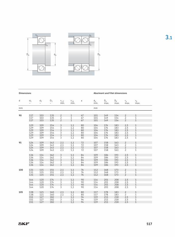
90 160 30 116 104 4 5 000 5 000 2,3 * 7218 BECBM – 90 117 103 135 2 1 67 101 149 154 2 1160 30 116 104 4 5 000 5 000 2,3 * 7218 BECBP – 117 103 135 2 1 67 101 149 154 2 1160 30 108 96,5 3,65 4 500 4 500 2,3 7218 BECBY 7218 BEP 117 103 135 2 1 67 101 149 154 2 1
190 43 166 146 5,3 4 500 4 500 5,2 * 7318 BEGAPH – 129 109 154 3 1,1 80 104 176 183 2,5 1190 43 166 146 5,3 4 500 4 500 5,2 * 7318 BECBM – 129 109 154 3 1,1 80 104 176 183 2,5 1190 43 166 146 5,3 4 500 4 500 5,2 * 7318 BECBP – 129 109 154 3 1,1 80 104 176 183 2,5 1190 43 165 146 5,2 4 000 4 000 5,2 7318 BECBY – 129 109 154 3 1,1 80 104 176 183 2,5 1190 43 156 134 4,8 4 000 4 300 5,2 – 7318 BEM 129 109 154 3 1,1 80 104 176 183 2,5 1190 43 156 134 4,8 4 000 4 000 5,2 – 7318 BEP 129 109 154 3 1,1 80 104 176 183 2,5 1
95 170 32 124 108 4 4 300 4 500 2,7 7219 BECBM – 95 124 109 143 2,1 1,1 72 107 158 163 2 1170 32 129 118 4,4 4 800 4 800 2,7 * 7219 BECBP – 124 109 143 2,1 1,1 72 107 158 163 2 1170 32 124 108 4 4 300 4 300 2,7 7219 BECBY 7219 BEP 124 109 143 2,1 1,1 72 107 158 163 2 1170 32 129 118 4,4 4 800 4 800 2,7 * 7219 BEGAPH – 124 109 143 2,1 1,1 72 107 158 163 2 1
200 45 180 163 5,7 4 300 4 300 6,05 * 7319 BECBM – 136 114 162 3 1,1 84 109 186 193 2,5 1200 45 180 163 5,7 4 300 4 300 6,05 * 7319 BECBP – 136 114 162 3 1,1 84 109 186 193 2,5 1200 45 190 176 6,1 4 300 4 300 6,05 7319 BECBY – 136 114 162 3 1,1 84 109 186 193 2,5 1200 45 168 150 5,2 3 800 4 000 6,05 – 7319 BEM 136 114 162 3 1,1 84 109 186 193 2,5 1200 45 168 150 5,2 3 800 3 800 6,05 – 7319 BEP 136 114 162 3 1,1 84 109 186 193 2,5 1
100 180 34 143 134 4,75 4 500 4 500 3,3 * 7220 BECBM – 100 131 115 151 2,1 1,1 76 112 168 173 2 1180 34 143 134 4,75 4 500 4 500 3,3 * 7220 BECBP – 131 115 151 2,1 1,1 76 112 168 173 2 1180 34 135 122 4,4 4 000 4 000 3,3 7220 BECBY 7220 BEP 131 115 151 2,1 1,1 76 112 168 173 2 1
215 47 216 208 6,95 4 000 4 000 7,5 * 7320 BECBM – 144 120 174 3 1,1 90 114 201 208 2,5 1215 47 216 208 6,95 4 000 4 000 7,5 * 7320 BECBP – 144 120 174 3 1,1 90 114 201 208 2,5 1215 47 203 190 6,4 3 600 3 600 7,5 7320 BECBY 7320 BEP 144 120 174 3 1,1 90 114 201 208 2,5 1215 47 203 190 6,4 3 600 3 600 7,5 – 7320 BEM 144 120 174 3 1,1 90 114 201 208 2,5 1
105 190 36 148 137 4,8 3 800 4 000 3,95 * 7221 BECBM – 105 138 121 160 2,1 1,1 80 117 178 183 2 1190 36 156 150 5,2 4 300 4 300 3,95 * 7221 BECBP – 138 121 160 2,1 1,1 80 117 178 183 2 1225 49 216 208 6,95 3 800 3 800 8,55 * 7321 BECBM – 151 127 182 3 1,1 94 119 211 218 2,5 1225 49 216 208 6,95 3 800 3 800 8,55 * 7321 BECBP – 151 127 182 3 1,1 94 119 211 218 2,5 1225 49 203 193 6,4 3 400 3 400 8,55 – 7321 BEP 151 127 182 3 1,1 94 119 211 218 2,5 1
3.1
Db
ra
rb
daDa
ra
ra
Principal dimensions Basic load ratings Fatigue load
limitSpeed ratings Mass Designations1) Dimensions Abutment and fillet dimensions
dynamic static Reference speed
Limiting speed
Universally matchable bearing
Basic design bearing
d D B C C0 Pu d d1 d2 D1 r1,2 r3,4 a da Da Db ra rb~ ~ ~ min . min . min . max . max . max . max .
mm kN kN r/min kg – mm mm
517
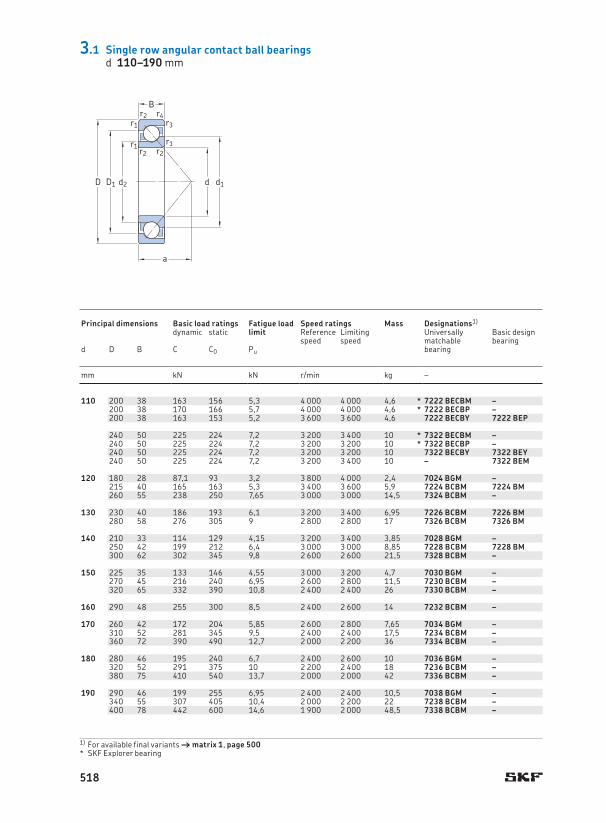
110 200 38 163 156 5,3 4 000 4 000 4,6 * 7222 BECBM – 110 144 127 168 2,1 1,1 84 122 188 193 2 1200 38 170 166 5,7 4 000 4 000 4,6 * 7222 BECBP – 144 127 168 2,1 1,1 84 122 188 193 2 1200 38 163 153 5,2 3 600 3 600 4,6 7222 BECBY 7222 BEP 144 127 168 2,1 1,1 84 122 188 193 2 1
240 50 225 224 7,2 3 200 3 400 10 * 7322 BECBM – 160 135 194 3 1,1 99 124 226 233 2,5 1240 50 225 224 7,2 3 200 3 200 10 * 7322 BECBP – 160 135 194 3 1,1 99 124 226 233 2,5 1240 50 225 224 7,2 3 200 3 200 10 7322 BECBY 7322 BEY 160 135 194 3 1,1 99 124 226 233 2,5 1240 50 225 224 7,2 3 200 3 400 10 – 7322 BEM 160 135 194 3 1,1 99 124 226 233 2,5 1
120 180 28 87,1 93 3,2 3 800 4 000 2,4 7024 BGM – 120 143 132 158 2 1 77 130 170 174 2 1215 40 165 163 5,3 3 400 3 600 5,9 7224 BCBM 7224 BM 157 138 180 2,1 1,1 90 132 203 208 2 1260 55 238 250 7,65 3 000 3 000 14,5 7324 BCBM – 178 153 211 3 1,5 107 134 246 253 2,5 1
130 230 40 186 193 6,1 3 200 3 400 6,95 7226 BCBM 7226 BM 130 169 149 193 3 1,1 96 144 216 222 2,5 1280 58 276 305 9 2 800 2 800 17 7326 BCBM 7326 BM 189 161 228 4 1,5 115 147 263 271 3 1,5
140 210 33 114 129 4,15 3 200 3 400 3,85 7028 BGM – 140 168 155 183 2 1 90 150 200 204 2 1250 42 199 212 6,4 3 000 3 000 8,85 7228 BCBM 7228 BM 183 163 210 3 1,1 103 154 236 243 2,5 1300 62 302 345 9,8 2 600 2 600 21,5 7328 BCBM – 203 172 243 4 1,5 123 158 283 291 3 1,5
150 225 35 133 146 4,55 3 000 3 200 4,7 7030 BGM – 150 178 166 197 2,1 1,1 96 162 213 218 2 1270 45 216 240 6,95 2 600 2 800 11,5 7230 BCBM – 197 175 226 3 1,1 111 164 256 263 2,5 1320 65 332 390 10,8 2 400 2 400 26 7330 BCBM – 216 183 259 4 1,5 131 167 303 311 3 1,5
160 290 48 255 300 8,5 2 400 2 600 14 7232 BCBM – 160 211 187 243 3 1,1 118 174 276 283 2,5 1
170 260 42 172 204 5,85 2 600 2 800 7,65 7034 BGM – 170 205 188 226 2,1 1,1 111 182 248 253 2 1310 52 281 345 9,5 2 400 2 400 17,5 7234 BCBM – 227 202 261 4 1,5 127 187 293 301 3 1,5360 72 390 490 12,7 2 000 2 200 36 7334 BCBM – 243 207 292 4 2 147 187 343 351 3 2
180 280 46 195 240 6,7 2 400 2 600 10 7036 BGM – 180 219 201 243 2,1 1,1 119 192 268 273 2 1320 52 291 375 10 2 200 2 400 18 7236 BCBM – 234 209 269 4 1,5 131 197 303 311 3 1,5380 75 410 540 13,7 2 000 2 000 42 7336 BCBM – 257 219 308 4 2 156 197 363 370 3 2
190 290 46 199 255 6,95 2 400 2 400 10,5 7038 BGM – 190 229 210 253 2,1 1,1 124 202 278 283 2 1340 55 307 405 10,4 2 000 2 200 22 7238 BCBM – 250 224 286 4 1,5 139 207 323 331 3 1,5400 78 442 600 14,6 1 900 2 000 48,5 7338 BCBM – 271 231 325 5 2 164 210 380 390 4 2
3.1 Single row angular contact ball bearingsd 110–190 mm
a
D1D
B
d d1
r2r3
r4
r1r2
r1r2
r1
d2
1) For available final variants † matrix 1, page 500SKF Explorer bearing *
Principal dimensions Basic load ratings Fatigue load
limitSpeed ratings Mass Designations1) Dimensions Abutment and fillet dimensions
dynamic static Reference speed
Limiting speed
Universally matchable bearing
Basic design bearing
d D B C C0 Pu d d1 d2 D1 r1,2 r3,4 a da Da Db ra rb~ ~ ~ min . min . min . max . max . max . max .
mm kN kN r/min kg – mm mm
518

110 200 38 163 156 5,3 4 000 4 000 4,6 * 7222 BECBM – 110 144 127 168 2,1 1,1 84 122 188 193 2 1200 38 170 166 5,7 4 000 4 000 4,6 * 7222 BECBP – 144 127 168 2,1 1,1 84 122 188 193 2 1200 38 163 153 5,2 3 600 3 600 4,6 7222 BECBY 7222 BEP 144 127 168 2,1 1,1 84 122 188 193 2 1
240 50 225 224 7,2 3 200 3 400 10 * 7322 BECBM – 160 135 194 3 1,1 99 124 226 233 2,5 1240 50 225 224 7,2 3 200 3 200 10 * 7322 BECBP – 160 135 194 3 1,1 99 124 226 233 2,5 1240 50 225 224 7,2 3 200 3 200 10 7322 BECBY 7322 BEY 160 135 194 3 1,1 99 124 226 233 2,5 1240 50 225 224 7,2 3 200 3 400 10 – 7322 BEM 160 135 194 3 1,1 99 124 226 233 2,5 1
120 180 28 87,1 93 3,2 3 800 4 000 2,4 7024 BGM – 120 143 132 158 2 1 77 130 170 174 2 1215 40 165 163 5,3 3 400 3 600 5,9 7224 BCBM 7224 BM 157 138 180 2,1 1,1 90 132 203 208 2 1260 55 238 250 7,65 3 000 3 000 14,5 7324 BCBM – 178 153 211 3 1,5 107 134 246 253 2,5 1
130 230 40 186 193 6,1 3 200 3 400 6,95 7226 BCBM 7226 BM 130 169 149 193 3 1,1 96 144 216 222 2,5 1280 58 276 305 9 2 800 2 800 17 7326 BCBM 7326 BM 189 161 228 4 1,5 115 147 263 271 3 1,5
140 210 33 114 129 4,15 3 200 3 400 3,85 7028 BGM – 140 168 155 183 2 1 90 150 200 204 2 1250 42 199 212 6,4 3 000 3 000 8,85 7228 BCBM 7228 BM 183 163 210 3 1,1 103 154 236 243 2,5 1300 62 302 345 9,8 2 600 2 600 21,5 7328 BCBM – 203 172 243 4 1,5 123 158 283 291 3 1,5
150 225 35 133 146 4,55 3 000 3 200 4,7 7030 BGM – 150 178 166 197 2,1 1,1 96 162 213 218 2 1270 45 216 240 6,95 2 600 2 800 11,5 7230 BCBM – 197 175 226 3 1,1 111 164 256 263 2,5 1320 65 332 390 10,8 2 400 2 400 26 7330 BCBM – 216 183 259 4 1,5 131 167 303 311 3 1,5
160 290 48 255 300 8,5 2 400 2 600 14 7232 BCBM – 160 211 187 243 3 1,1 118 174 276 283 2,5 1
170 260 42 172 204 5,85 2 600 2 800 7,65 7034 BGM – 170 205 188 226 2,1 1,1 111 182 248 253 2 1310 52 281 345 9,5 2 400 2 400 17,5 7234 BCBM – 227 202 261 4 1,5 127 187 293 301 3 1,5360 72 390 490 12,7 2 000 2 200 36 7334 BCBM – 243 207 292 4 2 147 187 343 351 3 2
180 280 46 195 240 6,7 2 400 2 600 10 7036 BGM – 180 219 201 243 2,1 1,1 119 192 268 273 2 1320 52 291 375 10 2 200 2 400 18 7236 BCBM – 234 209 269 4 1,5 131 197 303 311 3 1,5380 75 410 540 13,7 2 000 2 000 42 7336 BCBM – 257 219 308 4 2 156 197 363 370 3 2
190 290 46 199 255 6,95 2 400 2 400 10,5 7038 BGM – 190 229 210 253 2,1 1,1 124 202 278 283 2 1340 55 307 405 10,4 2 000 2 200 22 7238 BCBM – 250 224 286 4 1,5 139 207 323 331 3 1,5400 78 442 600 14,6 1 900 2 000 48,5 7338 BCBM – 271 231 325 5 2 164 210 380 390 4 2
3.1
Db
ra
rb
daDa
ra
ra
Principal dimensions Basic load ratings Fatigue load
limitSpeed ratings Mass Designations1) Dimensions Abutment and fillet dimensions
dynamic static Reference speed
Limiting speed
Universally matchable bearing
Basic design bearing
d D B C C0 Pu d d1 d2 D1 r1,2 r3,4 a da Da Db ra rb~ ~ ~ min . min . min . max . max . max . max .
mm kN kN r/min kg – mm mm
519
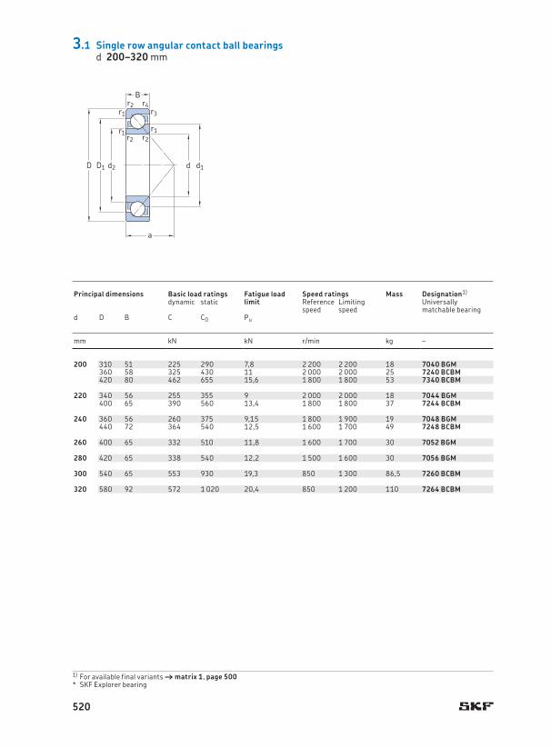
200 310 51 225 290 7,8 2 200 2 200 18 7040 BGM 200 243 223 269 2,1 1,1 145 234 285 333 2,1 1,1360 58 325 430 11 2 000 2 000 25 7240 BCBM 263 235 301 4 1,5 146 217 343 351 3 1,5420 80 462 655 15,6 1 800 1 800 53 7340 BCBM 287 247 340 5 2 170 220 400 410 4 2
220 340 56 255 355 9 2 000 2 000 18 7044 BGM 220 266 246 295 3 1,1 145 234 326 333 2,5 1,1400 65 390 560 13,4 1 800 1 800 37 7244 BCBM 291 259 334 4 1,5 164 237 383 391 3 1,5
240 360 56 260 375 9,15 1 800 1 900 19 7048 BGM 240 286 265 315 3 1,1 154 254 346 353 2,5 1,1440 72 364 540 12,5 1 600 1 700 49 7248 BCBM 322 292 361 4 1,5 180 257 423 431 3 1,5
260 400 65 332 510 11,8 1 600 1 700 30 7052 BGM 260 314 288 348 4 1,5 171 276 373 380 3 1,5
280 420 65 338 540 12,2 1 500 1 600 30 7056 BGM 280 335 311 367 4 1,5 179 298 402 411 3 1,5
300 540 65 553 930 19,3 850 1 300 86,5 7260 BCBM 300 395 351 450 5 2,1 219 322 518 528 4 2
320 580 92 572 1 020 20,4 850 1 200 110 7264 BCBM 320 427 383 487 5 2 236 342 558 568 4 2
3.1 Single row angular contact ball bearingsd 200–320 mm
a
D1D
B
d d1
r2r3
r4
r1r2
r1r2
r1
d2
1) For available final variants † matrix 1, page 500SKF Explorer bearing *
Principal dimensions Basic load ratings Fatigue load
limitSpeed ratings Mass Designation1) Dimensions Abutment and fillet dimensions
dynamic static Reference speed
Limiting speed
Universally matchable bearing
d D B C C0 Pu d d1 d2 D1 r1,2 r3,4 a da Da Db ra rb~ ~ ~ min . min . min . max . max . max . max .
mm kN kN r/min kg – mm mm
520

200 310 51 225 290 7,8 2 200 2 200 18 7040 BGM 200 243 223 269 2,1 1,1 145 234 285 333 2,1 1,1360 58 325 430 11 2 000 2 000 25 7240 BCBM 263 235 301 4 1,5 146 217 343 351 3 1,5420 80 462 655 15,6 1 800 1 800 53 7340 BCBM 287 247 340 5 2 170 220 400 410 4 2
220 340 56 255 355 9 2 000 2 000 18 7044 BGM 220 266 246 295 3 1,1 145 234 326 333 2,5 1,1400 65 390 560 13,4 1 800 1 800 37 7244 BCBM 291 259 334 4 1,5 164 237 383 391 3 1,5
240 360 56 260 375 9,15 1 800 1 900 19 7048 BGM 240 286 265 315 3 1,1 154 254 346 353 2,5 1,1440 72 364 540 12,5 1 600 1 700 49 7248 BCBM 322 292 361 4 1,5 180 257 423 431 3 1,5
260 400 65 332 510 11,8 1 600 1 700 30 7052 BGM 260 314 288 348 4 1,5 171 276 373 380 3 1,5
280 420 65 338 540 12,2 1 500 1 600 30 7056 BGM 280 335 311 367 4 1,5 179 298 402 411 3 1,5
300 540 65 553 930 19,3 850 1 300 86,5 7260 BCBM 300 395 351 450 5 2,1 219 322 518 528 4 2
320 580 92 572 1 020 20,4 850 1 200 110 7264 BCBM 320 427 383 487 5 2 236 342 558 568 4 2
3.1
Db
ra
rb
daDa
ra
ra
Principal dimensions Basic load ratings Fatigue load
limitSpeed ratings Mass Designation1) Dimensions Abutment and fillet dimensions
dynamic static Reference speed
Limiting speed
Universally matchable bearing
d D B C C0 Pu d d1 d2 D1 r1,2 r3,4 a da Da Db ra rb~ ~ ~ min . min . min . max . max . max . max .
mm kN kN r/min kg – mm mm
521

10 30 14 7,61 4,3 0,183 22 000 24 000 0,051 – 3200 ATN9 10 15,8 25 0,6 16 14,4 25,6 0,6
12 32 15,9 10,1 5,6 0,24 20 000 22 000 0,058 – 3201 ATN9 12 17,2 27,7 0,6 19 16,4 27,6 0,6
15 35 15,9 11,2 6,8 0,285 17 000 18 000 0,066 – 3202 ATN9 15 20,2 30,7 0,6 21 19,4 30,6 0,642 19 15,1 9,3 0,4 15 000 16 000 0,13 – 3302 ATN9 23,7 35,7 1 24 20,6 36,4 1
17 40 17,5 14,3 8,8 0,365 15 000 16 000 0,096 – 3203 ATN9 17 23,3 35 0,6 23 21,4 35,6 0,647 22,2 21,6 12,7 0,54 14 000 14 000 0,18 – 3303 ATN9 27,3 38,8 1 28 22,6 41,4 1
20 47 20,6 20 12 0,51 14 000 14 000 0,16 * 3204 A * 3204 ATN9 20 27,7 40,9 1 28 25,6 41,4 152 22,2 23,6 14,6 0,62 13 000 13 000 0,22 * 3304 A * 3304 ATN9 29,9 44 1,1 30 27 45 1
25 52 20,6 21,6 14,3 0,6 12 000 12 000 0,18 * 3205 A * 3205 ATN9 25 32,7 45,9 1 30 31 46 162 25,4 32 20,4 0,865 11 000 11 000 0,35 * 3305 A * 3305 ATN9 35,7 53,4 1,1 36 32 55 1
30 62 23,8 30 20,4 0,865 10 000 10 000 0,29 * 3206 A * 3206 ATN9 30 38,7 55,2 1 36 36 56 172 30,2 41,5 27,5 1,16 9 000 9 000 0,52 * 3306 A * 3306 ATN9 39,8 64,1 1,1 42 37 65 1
35 72 27 40 28 1,18 9 000 9 000 0,44 * 3207 A * 3207 ATN9 35 45,4 63,9 1,1 42 42 65 180 34,9 52 35,5 1,5 8 500 8 500 0,74 * 3307 A * 3307 ATN9 44,6 70,5 1,5 47 44 71 1,580 34,9 52,7 41,5 1,76 7 500 8 000 0,79 3307 DJ1 – 52,8 69 1,5 76 44 71 1,5
40 80 30,2 47,5 34 1,43 8 000 8 000 0,57 * 3208 A * 3208 ATN9 40 47,8 72,1 1,1 46 47 73 190 36,5 64 44 1,86 7 500 7 500 0,93 * 3308 A * 3308 ATN9 50,8 80,5 1,5 53 49 81 1,590 36,5 49,4 41,5 1,76 6 700 7 000 1,2 3308 DNRCBM – 60,1 79,5 1,5 71 49 81 1,590 36,5 68,9 57 2,45 6 700 7 000 1,05 3308 DMA 3308 DTN9 59,4 80,3 1,5 84 49 81 1,5
45 85 30,2 51 39 1,63 7 500 7 500 0,63 * 3209 A * 3209 ATN9 45 52,8 77,1 1,1 46 52 78 1100 39,7 75 53 2,24 6 700 6 700 1,25 * 3309 A * 3309 ATN9 55,6 90 1,5 58 54 91 1,5100 39,7 61,8 52 2,2 6 000 6 300 1,5 3309 DNRCBM – 68 87,1 1,5 79 54 91 1,5100 39,7 79,3 69,5 3 6 000 6 300 1,65 3309 DMA – 70 86,4 1,5 93 54 91 1,5
50 90 30,2 51 39 1,66 7 000 7 000 0,65 * 3210 A * 3210 ATN9 50 57,8 82,1 1,1 52 57 83 1110 44,4 90 64 2,75 6 000 6 000 1,7 * 3310 A * 3310 ATN9 62 99,5 2 65 61 99,5 2110 44,4 81,9 69,5 3 5 300 5 600 1,95 3310 DNRCBM – 74,6 87 2 102 61 99 2110 44,4 93,6 85 3,6 5 300 5 600 2,2 3310 DMA – 76,5 94,2 2 102 61 99 2
D1D d d1
a
B
r1r2
r1r2
32 A, 33 A 33 D 33 DNRCBM1)
3.2 Double row angular contact ball bearingsd 10–50 mm
Principal dimensions Basic load ratings Fatigue load
limitSpeed ratings Mass Designations2) Dimensions Abutment and fillet dimensions
dynamic static Reference speed
Limiting speed
Bearing withmetal cage polyamide
caged D B C C0 Pu d d1 D1 r1,2 a da Da ra~ ~ min . min . max . max .
mm kN kN r/min kg – mm mm
1) For dimensions of snap ring groove and snap ring † table 4, page 4882) For available final variants † matrix 2, page 501
SKF Explorer bearing *
522

10 30 14 7,61 4,3 0,183 22 000 24 000 0,051 – 3200 ATN9 10 15,8 25 0,6 16 14,4 25,6 0,6
12 32 15,9 10,1 5,6 0,24 20 000 22 000 0,058 – 3201 ATN9 12 17,2 27,7 0,6 19 16,4 27,6 0,6
15 35 15,9 11,2 6,8 0,285 17 000 18 000 0,066 – 3202 ATN9 15 20,2 30,7 0,6 21 19,4 30,6 0,642 19 15,1 9,3 0,4 15 000 16 000 0,13 – 3302 ATN9 23,7 35,7 1 24 20,6 36,4 1
17 40 17,5 14,3 8,8 0,365 15 000 16 000 0,096 – 3203 ATN9 17 23,3 35 0,6 23 21,4 35,6 0,647 22,2 21,6 12,7 0,54 14 000 14 000 0,18 – 3303 ATN9 27,3 38,8 1 28 22,6 41,4 1
20 47 20,6 20 12 0,51 14 000 14 000 0,16 * 3204 A * 3204 ATN9 20 27,7 40,9 1 28 25,6 41,4 152 22,2 23,6 14,6 0,62 13 000 13 000 0,22 * 3304 A * 3304 ATN9 29,9 44 1,1 30 27 45 1
25 52 20,6 21,6 14,3 0,6 12 000 12 000 0,18 * 3205 A * 3205 ATN9 25 32,7 45,9 1 30 31 46 162 25,4 32 20,4 0,865 11 000 11 000 0,35 * 3305 A * 3305 ATN9 35,7 53,4 1,1 36 32 55 1
30 62 23,8 30 20,4 0,865 10 000 10 000 0,29 * 3206 A * 3206 ATN9 30 38,7 55,2 1 36 36 56 172 30,2 41,5 27,5 1,16 9 000 9 000 0,52 * 3306 A * 3306 ATN9 39,8 64,1 1,1 42 37 65 1
35 72 27 40 28 1,18 9 000 9 000 0,44 * 3207 A * 3207 ATN9 35 45,4 63,9 1,1 42 42 65 180 34,9 52 35,5 1,5 8 500 8 500 0,74 * 3307 A * 3307 ATN9 44,6 70,5 1,5 47 44 71 1,580 34,9 52,7 41,5 1,76 7 500 8 000 0,79 3307 DJ1 – 52,8 69 1,5 76 44 71 1,5
40 80 30,2 47,5 34 1,43 8 000 8 000 0,57 * 3208 A * 3208 ATN9 40 47,8 72,1 1,1 46 47 73 190 36,5 64 44 1,86 7 500 7 500 0,93 * 3308 A * 3308 ATN9 50,8 80,5 1,5 53 49 81 1,590 36,5 49,4 41,5 1,76 6 700 7 000 1,2 3308 DNRCBM – 60,1 79,5 1,5 71 49 81 1,590 36,5 68,9 57 2,45 6 700 7 000 1,05 3308 DMA 3308 DTN9 59,4 80,3 1,5 84 49 81 1,5
45 85 30,2 51 39 1,63 7 500 7 500 0,63 * 3209 A * 3209 ATN9 45 52,8 77,1 1,1 46 52 78 1100 39,7 75 53 2,24 6 700 6 700 1,25 * 3309 A * 3309 ATN9 55,6 90 1,5 58 54 91 1,5100 39,7 61,8 52 2,2 6 000 6 300 1,5 3309 DNRCBM – 68 87,1 1,5 79 54 91 1,5100 39,7 79,3 69,5 3 6 000 6 300 1,65 3309 DMA – 70 86,4 1,5 93 54 91 1,5
50 90 30,2 51 39 1,66 7 000 7 000 0,65 * 3210 A * 3210 ATN9 50 57,8 82,1 1,1 52 57 83 1110 44,4 90 64 2,75 6 000 6 000 1,7 * 3310 A * 3310 ATN9 62 99,5 2 65 61 99,5 2110 44,4 81,9 69,5 3 5 300 5 600 1,95 3310 DNRCBM – 74,6 87 2 102 61 99 2110 44,4 93,6 85 3,6 5 300 5 600 2,2 3310 DMA – 76,5 94,2 2 102 61 99 2
3.2
daDa
ra
ra
Principal dimensions Basic load ratings Fatigue load
limitSpeed ratings Mass Designations2) Dimensions Abutment and fillet dimensions
dynamic static Reference speed
Limiting speed
Bearing withmetal cage polyamide
caged D B C C0 Pu d d1 D1 r1,2 a da Da ra~ ~ min . min . max . max .
mm kN kN r/min kg – mm mm
523

55 100 33,3 60 47,5 2 6 300 6 300 0,91 * 3211 A * 3211 ATN9 55 63,2 92,3 1,5 57 63 91 1,5120 49,2 112 81,5 3,45 5 300 5 300 2,65 * 3311 A * 3311 ATN9 68,4 109 2 72 66 109 2120 49,2 95,6 83 3,55 5 000 5 300 2,55 3311 DNRCBM – 81,6 107 2 97 66 109 2120 49,2 111 100 4,3 4 800 5 000 2,8 3311 DMA – 81,3 105 2 114 66 109 2
60 110 36,5 73,5 58,5 2,5 5 600 5 600 1,2 * 3212 A * 3212 ATN9 60 68,8 101 1,5 63 69 101 1,5130 54 127 95 4,05 5 000 5 000 2,8 * 3312 A – 74,3 118 2,1 78 72 118 2
65 120 38,1 80,6 73,5 3,1 4 500 4 800 1,75 3213 A – 65 85 103 1,5 71 74 111 1,5140 58,7 146 110 4,55 4 500 4 500 4,1 * 3313 A – 78,5 116 2,1 84 77 128 2140 58,7 138 122 5,1 4 300 4 500 4 3313 DNRCBM – 95,1 126 2,1 114 77 128 2
70 125 39,7 88,4 80 3,4 4 300 4 500 1,9 3214 A – 70 88,5 107 1,5 74 79 116 1,5150 63,5 163 125 5 4 300 4 300 5,05 * 3314 A – 84,2 125 2,1 89 82 138 2
75 130 41,3 95,6 88 3,75 4 300 4 500 2,1 3215 A – 75 91,9 112 1,5 77 84 121 1,5160 68,3 176 140 5,5 4 000 4 000 5,55 * 3315 A – 88,8 135 2,1 97 87 148 2
80 140 44,4 106 95 3,9 4 000 4 300 2,65 3216 A – 80 97,7 120 2 82 91 129 2170 68,3 193 156 6 3 800 3 800 6,8 * 3316 A – 108 143 2,1 101 92 158 2
85 150 49,2 124 110 4,4 3 600 3 800 3,4 3217 A – 85 104 128 2 88 96 139 2180 73 208 176 6,55 3 600 3 600 8,3 * 3317 A – 116 153 3 107 99 166 2,5
90 160 52,4 130 120 4,55 3 400 3 600 4,15 3218 A – 90 111 139 2 94 101 149 2190 73 208 180 6,4 3 400 3 400 9,25 * 3318 A – 123 160 3 112 104 176 2,5
95 170 55,6 159 146 5,4 3 200 3 400 5 3219 A – 95 119 147 2,1 101 107 158 2200 77,8 240 216 7,5 3 200 3 200 11 * 3319 A – 127 168 3 127 109 186 2,5
100 180 60,3 178 166 6 3 000 3 200 6,1 3220 A – 100 125 155 2,1 107 112 168 2215 82,6 255 255 8,65 2 600 2 800 13,5 3320 A – 136 180 3 127 114 201 2,5
110 200 69,8 212 212 7,2 2 800 2 800 8,8 3222 A – 110 139 173 2,1 119 122 188 2240 92,1 291 305 9,8 2 400 2 600 19 3322 A – 153 200 3 142 124 226 2,5
3.2 Double row angular contact ball bearingsd 55–110 mm
D1D d d1
a
B
r1r2
r1r2
1) For dimensions of snap ring groove and snap ring † table 4, page 4882) For available final variants † matrix 2, page 501
SKF Explorer bearing *
Principal dimensions Basic load ratings Fatigue load
limitSpeed ratings Mass Designations2) Dimensions Abutment and fillet dimensions
dynamic static Reference speed
Limiting speed
Bearing withmetal cage polyamide
caged D B C C0 Pu d d1 D1 r1,2 a da Da ra~ ~ min . min . max . max .
mm kN kN r/min kg – mm mm
32 A, 33 A 33 D 33 DNRCBM1)
524

55 100 33,3 60 47,5 2 6 300 6 300 0,91 * 3211 A * 3211 ATN9 55 63,2 92,3 1,5 57 63 91 1,5120 49,2 112 81,5 3,45 5 300 5 300 2,65 * 3311 A * 3311 ATN9 68,4 109 2 72 66 109 2120 49,2 95,6 83 3,55 5 000 5 300 2,55 3311 DNRCBM – 81,6 107 2 97 66 109 2120 49,2 111 100 4,3 4 800 5 000 2,8 3311 DMA – 81,3 105 2 114 66 109 2
60 110 36,5 73,5 58,5 2,5 5 600 5 600 1,2 * 3212 A * 3212 ATN9 60 68,8 101 1,5 63 69 101 1,5130 54 127 95 4,05 5 000 5 000 2,8 * 3312 A – 74,3 118 2,1 78 72 118 2
65 120 38,1 80,6 73,5 3,1 4 500 4 800 1,75 3213 A – 65 85 103 1,5 71 74 111 1,5140 58,7 146 110 4,55 4 500 4 500 4,1 * 3313 A – 78,5 116 2,1 84 77 128 2140 58,7 138 122 5,1 4 300 4 500 4 3313 DNRCBM – 95,1 126 2,1 114 77 128 2
70 125 39,7 88,4 80 3,4 4 300 4 500 1,9 3214 A – 70 88,5 107 1,5 74 79 116 1,5150 63,5 163 125 5 4 300 4 300 5,05 * 3314 A – 84,2 125 2,1 89 82 138 2
75 130 41,3 95,6 88 3,75 4 300 4 500 2,1 3215 A – 75 91,9 112 1,5 77 84 121 1,5160 68,3 176 140 5,5 4 000 4 000 5,55 * 3315 A – 88,8 135 2,1 97 87 148 2
80 140 44,4 106 95 3,9 4 000 4 300 2,65 3216 A – 80 97,7 120 2 82 91 129 2170 68,3 193 156 6 3 800 3 800 6,8 * 3316 A – 108 143 2,1 101 92 158 2
85 150 49,2 124 110 4,4 3 600 3 800 3,4 3217 A – 85 104 128 2 88 96 139 2180 73 208 176 6,55 3 600 3 600 8,3 * 3317 A – 116 153 3 107 99 166 2,5
90 160 52,4 130 120 4,55 3 400 3 600 4,15 3218 A – 90 111 139 2 94 101 149 2190 73 208 180 6,4 3 400 3 400 9,25 * 3318 A – 123 160 3 112 104 176 2,5
95 170 55,6 159 146 5,4 3 200 3 400 5 3219 A – 95 119 147 2,1 101 107 158 2200 77,8 240 216 7,5 3 200 3 200 11 * 3319 A – 127 168 3 127 109 186 2,5
100 180 60,3 178 166 6 3 000 3 200 6,1 3220 A – 100 125 155 2,1 107 112 168 2215 82,6 255 255 8,65 2 600 2 800 13,5 3320 A – 136 180 3 127 114 201 2,5
110 200 69,8 212 212 7,2 2 800 2 800 8,8 3222 A – 110 139 173 2,1 119 122 188 2240 92,1 291 305 9,8 2 400 2 600 19 3322 A – 153 200 3 142 124 226 2,5
3.2
daDa
ra
ra
Principal dimensions Basic load ratings Fatigue load
limitSpeed ratings Mass Designations2) Dimensions Abutment and fillet dimensions
dynamic static Reference speed
Limiting speed
Bearing withmetal cage polyamide
caged D B C C0 Pu d d1 D1 r1,2 a da Da ra~ ~ min . min . max . max .
mm kN kN r/min kg – mm mm
525
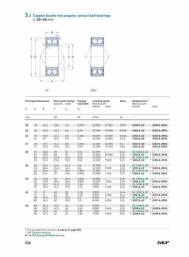
10 30 14,3 7,61 4,3 0,183 24 000 17 000 0,051 3200 A-2Z 3200 A-2RS1 10 15,8 25 0,6 16 14,4 15,5 25,6 0,6
12 32 15,9 10,1 5,6 0,24 22 000 15 000 0,058 3201 A-2Z 3201 A-2RS1 12 17,2 27,7 0,6 19 16,4 17 27,6 0,6
15 35 15,9 11,2 6,8 0,285 18 000 14 000 0,066 3202 A-2Z 3202 A-2RS1 15 20,2 30,7 0,6 21 19,4 20 30,6 0,642 19 15,1 9,3 0,4 16 000 12 000 0,13 3302 A-2Z 3302 A-2RS1 23,7 35,7 1 24 20,6 23,5 36,4 1
17 40 17,5 14,3 8,8 0,365 16 000 12 000 0,1 3203 A-2Z 3203 A-2RS1 17 23,3 35 0,6 23 21,4 23 35,6 0,647 22,2 21,6 12,7 0,54 14 000 11 000 0,18 3303 A-2Z 3303 A-2RS1 27,3 38,8 1 28 22,6 25,5 41,4 1
20 47 20,6 20 12 0,51 14 000 – 0,16 E2.3204 A-2Z – 20 27,7 40,9 1 28 25,6 27,5 41,4 147 20,6 20 12 0,51 14 000 10 000 0,16 * 3204 A-2Z * 3204 A-2RS1 27,7 40,9 1 28 25,6 27,5 41,4 152 22,2 23,6 14,6 0,62 13 000 – 0,22 E2.3304 A-2Z – 29,9 44 1,1 30 27 29,5 45 152 22,2 23,6 14,6 0,62 13 000 9 000 0,22 * 3304 A-2Z * 3304 A-2RS1 29,9 44 1,1 30 27 29,5 45 1
25 52 20,6 21,6 14,3 0,6 12 000 – 0,18 E2.3205 A-2Z – 25 32,7 45,9 1 30 30,6 32,5 46,4 152 20,6 21,6 14,3 0,6 12 000 8 500 0,18 * 3205 A-2Z * 3205 A-2RS1 32,7 45,9 1 30 30,6 32,5 46,4 162 25,4 32 20,4 0,865 11 000 – 0,35 E2.3305 A-2Z – 35,7 53,4 1,1 36 32 35,5 55 162 25,4 32 20,4 0,865 11 000 7 500 0,35 * 3305 A-2Z * 3305 A-2RS1 35,7 53,4 1,1 36 32 35,5 55 1
30 62 23,8 30 20,4 0,865 10 000 – 0,29 E2.3206 A-2Z – 30 38,7 55,2 1 36 35,6 38,5 56,4 162 23,8 28,6 20,4 0,865 10 000 7 500 0,29 * 3206 A-2Z * 3206 A-2RS1 38,7 55,2 1 36 35,6 38,5 56,4 172 30,2 41,5 27,5 1,16 9 000 – 0,52 E2.3306 A-2Z – 39,8 64,1 1,1 42 37 39,5 65 172 30,2 41,5 27,5 1,16 9 000 6 300 0,52 * 3306 A-2Z * 3306 A-2RS1 39,8 64,1 1,1 42 37 39,5 65 1
35 72 27 40 28 1,18 9 000 – 0,44 E2.3207 A-2Z – 35 45,4 63,9 1,1 42 42 45 65 172 27 40 28 1,18 9 000 6 300 0,44 * 3207 A-2Z * 3207 A-2RS1 45,4 63,9 1,1 42 42 45 65 180 34,9 52 35,5 1,5 8 500 – 0,74 E2.3307 A-2Z – 44,6 70,5 1,5 47 44 44,5 71 1,580 34,9 52 35,5 1,5 8 500 6 000 0,74 * 3307 A-2Z * 3307 A-2RS1 44,6 70,5 1,5 47 44 44,5 71 1,5
40 80 30,2 47,5 34 1,43 8 000 – 0,57 E2.3208 A-2Z – 40 47,8 72,1 1,1 46 47 48 73 180 30,2 47,5 34 1,43 8 000 5 600 0,57 * 3208 A-2Z * 3208 A-2RS1 47,8 72,1 1,1 46 47 48 73 190 36,5 64 44 1,86 7 500 – 0,93 E2.3308 A-2Z – 50,8 80,5 1,5 53 49 50,5 81 1,590 36,5 64 44 1,86 7 500 5 000 0,93 * 3308 A-2Z * 3308 A-2RS1 50,8 80,5 1,5 53 49 50,5 81 1,5
2Z 2RS1
3.3 Capped double row angular contact ball bearingsd 10–40 mm
D1D d d1
a
B
r1
r1r2
r2
1) For available final variants † matrix 2, page 501SKF Explorer bearing *
E2 † SKF Energy Efficient bearing
Principal dimensions Basic load ratings Fatigue
load limitLimiting speed Mass Designations1) Dimensions Abutment and fillet dimensions
dynamic static Bearing with Bearing withshields seals shields seals
d D B C C0 Pu d d1 D1 r1,2 a da da Da ra~ ~ min . min . max . max . max .
mm kN kN r/min kg – mm mm
526
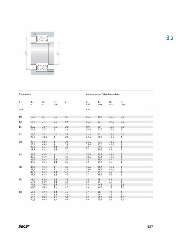
10 30 14,3 7,61 4,3 0,183 24 000 17 000 0,051 3200 A-2Z 3200 A-2RS1 10 15,8 25 0,6 16 14,4 15,5 25,6 0,6
12 32 15,9 10,1 5,6 0,24 22 000 15 000 0,058 3201 A-2Z 3201 A-2RS1 12 17,2 27,7 0,6 19 16,4 17 27,6 0,6
15 35 15,9 11,2 6,8 0,285 18 000 14 000 0,066 3202 A-2Z 3202 A-2RS1 15 20,2 30,7 0,6 21 19,4 20 30,6 0,642 19 15,1 9,3 0,4 16 000 12 000 0,13 3302 A-2Z 3302 A-2RS1 23,7 35,7 1 24 20,6 23,5 36,4 1
17 40 17,5 14,3 8,8 0,365 16 000 12 000 0,1 3203 A-2Z 3203 A-2RS1 17 23,3 35 0,6 23 21,4 23 35,6 0,647 22,2 21,6 12,7 0,54 14 000 11 000 0,18 3303 A-2Z 3303 A-2RS1 27,3 38,8 1 28 22,6 25,5 41,4 1
20 47 20,6 20 12 0,51 14 000 – 0,16 E2.3204 A-2Z – 20 27,7 40,9 1 28 25,6 27,5 41,4 147 20,6 20 12 0,51 14 000 10 000 0,16 * 3204 A-2Z * 3204 A-2RS1 27,7 40,9 1 28 25,6 27,5 41,4 152 22,2 23,6 14,6 0,62 13 000 – 0,22 E2.3304 A-2Z – 29,9 44 1,1 30 27 29,5 45 152 22,2 23,6 14,6 0,62 13 000 9 000 0,22 * 3304 A-2Z * 3304 A-2RS1 29,9 44 1,1 30 27 29,5 45 1
25 52 20,6 21,6 14,3 0,6 12 000 – 0,18 E2.3205 A-2Z – 25 32,7 45,9 1 30 30,6 32,5 46,4 152 20,6 21,6 14,3 0,6 12 000 8 500 0,18 * 3205 A-2Z * 3205 A-2RS1 32,7 45,9 1 30 30,6 32,5 46,4 162 25,4 32 20,4 0,865 11 000 – 0,35 E2.3305 A-2Z – 35,7 53,4 1,1 36 32 35,5 55 162 25,4 32 20,4 0,865 11 000 7 500 0,35 * 3305 A-2Z * 3305 A-2RS1 35,7 53,4 1,1 36 32 35,5 55 1
30 62 23,8 30 20,4 0,865 10 000 – 0,29 E2.3206 A-2Z – 30 38,7 55,2 1 36 35,6 38,5 56,4 162 23,8 28,6 20,4 0,865 10 000 7 500 0,29 * 3206 A-2Z * 3206 A-2RS1 38,7 55,2 1 36 35,6 38,5 56,4 172 30,2 41,5 27,5 1,16 9 000 – 0,52 E2.3306 A-2Z – 39,8 64,1 1,1 42 37 39,5 65 172 30,2 41,5 27,5 1,16 9 000 6 300 0,52 * 3306 A-2Z * 3306 A-2RS1 39,8 64,1 1,1 42 37 39,5 65 1
35 72 27 40 28 1,18 9 000 – 0,44 E2.3207 A-2Z – 35 45,4 63,9 1,1 42 42 45 65 172 27 40 28 1,18 9 000 6 300 0,44 * 3207 A-2Z * 3207 A-2RS1 45,4 63,9 1,1 42 42 45 65 180 34,9 52 35,5 1,5 8 500 – 0,74 E2.3307 A-2Z – 44,6 70,5 1,5 47 44 44,5 71 1,580 34,9 52 35,5 1,5 8 500 6 000 0,74 * 3307 A-2Z * 3307 A-2RS1 44,6 70,5 1,5 47 44 44,5 71 1,5
40 80 30,2 47,5 34 1,43 8 000 – 0,57 E2.3208 A-2Z – 40 47,8 72,1 1,1 46 47 48 73 180 30,2 47,5 34 1,43 8 000 5 600 0,57 * 3208 A-2Z * 3208 A-2RS1 47,8 72,1 1,1 46 47 48 73 190 36,5 64 44 1,86 7 500 – 0,93 E2.3308 A-2Z – 50,8 80,5 1,5 53 49 50,5 81 1,590 36,5 64 44 1,86 7 500 5 000 0,93 * 3308 A-2Z * 3308 A-2RS1 50,8 80,5 1,5 53 49 50,5 81 1,5
3.3
daDa
ra
ra
Principal dimensions Basic load ratings Fatigue
load limitLimiting speed Mass Designations1) Dimensions Abutment and fillet dimensions
dynamic static Bearing with Bearing withshields seals shields seals
d D B C C0 Pu d d1 D1 r1,2 a da da Da ra~ ~ min . min . max . max . max .
mm kN kN r/min kg – mm mm
527

45 85 30,2 51 39 1,63 7 500 – 0,63 E2.3209 A-2Z – 45 52,8 77,1 1,1 49 52 52,5 78 185 30,2 51 39 1,63 7 500 5 300 0,63 * 3209 A-2Z * 3209 A-2RS1 52,8 77,1 1,1 46 52 52,5 78 1100 39,7 75 53 2,24 6 700 – 1,25 E2.3309 A-2Z – 55,6 90 1,5 58 54 91 91 1,5100 39,7 75 53 2,24 6 700 4 800 1,25 * 3309 A-2Z * 3309 A-2RS1 55,6 90 1,5 58 54 91 91 1,5
50 90 30,2 51 39 1,66 7 000 – 0,65 E2.3210 A-2Z – 50 57,8 82,1 1,1 52 57 57,5 83 190 30,2 51 39 1,66 7 000 4 800 0,65 * 3210 A-2Z * 3210 A-2RS1 57,8 82,1 1,1 52 57 57,5 83 1110 44,4 90 64 2,75 6 000 – 1,7 E2.3310 A-2Z – 62 99,5 2 65 61 61,5 99,5 2110 44,4 90 64 2,75 6 000 4 300 1,7 * 3310 A-2Z * 3310 A-2RS1 62 99,5 2 65 61 61,5 99,5 2
55 100 33,3 60 47,5 2 6 300 – 0,91 E2.3211 A-2Z – 55 63,2 92,3 1,5 57 63 63 91 1,5100 33,3 60 47,5 2 6 300 4 500 0,91 * 3211 A-2Z * 3211 A-2RS1 63,2 92,3 1,5 57 63 63 91 1,5120 49,2 112 81,5 3,45 5 300 – 2,65 E2.3311 A-2Z – 68,4 109 2 72 66 68 109 2120 49,2 112 81,5 3,45 5 300 3 800 2,65 * 3311 A-2Z * 3311 A-2RS1 68,4 109 2 72 66 68 109 2
60 110 36,5 73,5 58,5 2,5 5 600 – 1,2 E2.3212 A-2Z – 60 68,8 101 1,5 63 68,5 68,5 101 1,5110 36,5 73,5 58,5 2,5 5 600 4 000 1,2 * 3212 A-2Z * 3212 A-2RS1 68,8 101 1,5 63 68,5 68,5 101 1,5130 54 127 95 4,05 5 000 – 2,8 E2.3312 A-2Z – 74,3 118 2,1 78 72 73 118 2130 54 127 95 4,05 5 000 – 2,8 * 3312 A-2Z – 74,3 118 2,1 78 72 73 118 2
65 120 38,1 80,6 73,5 3,1 4 800 3 600 1,75 3213 A-2Z 3213 A-2RS1 65 85 103 1,5 71 74 76 111 1,5140 58,7 146 110 4,55 4 500 – 4,1 * 3313 A-2Z – 78,5 116 2,1 84 77 78,5 128 2
70 125 39,7 88,4 80 3,4 4 500 – 1,9 3214 A-2Z – 70 88,5 107 1,5 74 79 82 116 1,5150 63,5 163 125 5 4 300 – 5,05 * 3314 A-2Z – 84,2 125 2,1 89 82 84 138 2
75 130 41,3 95,6 88 3,75 4 500 – 2,1 3215 A-2Z – 75 91,9 112 1,5 77 84 84 121 1,5160 68,3 176 140 5,5 4 000 – 5,6 * 3315 A-2Z – 88,8 135 2,1 97 87 88,5 148 2
D1D d d1
a
B
r1
r1r2
r2
3.3 Capped double row angular contact ball bearingsd 45–75 mm
1) For available final variants † matrix 2, page 501SKF Explorer bearing *
E2 † SKF Energy Efficient bearing
2Z 2RS1
Principal dimensions Basic load ratings Fatigue
load limitLimiting speed Mass Designations1) Dimensions Abutment and fillet dimensions
dynamic static Bearing with Bearing withshields seals shields seals
d D B C C0 Pu d d1 D1 r1,2 a da da Da ra~ ~ min . min . max . max . max .
mm kN kN r/min kg – mm mm
528

45 85 30,2 51 39 1,63 7 500 – 0,63 E2.3209 A-2Z – 45 52,8 77,1 1,1 49 52 52,5 78 185 30,2 51 39 1,63 7 500 5 300 0,63 * 3209 A-2Z * 3209 A-2RS1 52,8 77,1 1,1 46 52 52,5 78 1100 39,7 75 53 2,24 6 700 – 1,25 E2.3309 A-2Z – 55,6 90 1,5 58 54 91 91 1,5100 39,7 75 53 2,24 6 700 4 800 1,25 * 3309 A-2Z * 3309 A-2RS1 55,6 90 1,5 58 54 91 91 1,5
50 90 30,2 51 39 1,66 7 000 – 0,65 E2.3210 A-2Z – 50 57,8 82,1 1,1 52 57 57,5 83 190 30,2 51 39 1,66 7 000 4 800 0,65 * 3210 A-2Z * 3210 A-2RS1 57,8 82,1 1,1 52 57 57,5 83 1110 44,4 90 64 2,75 6 000 – 1,7 E2.3310 A-2Z – 62 99,5 2 65 61 61,5 99,5 2110 44,4 90 64 2,75 6 000 4 300 1,7 * 3310 A-2Z * 3310 A-2RS1 62 99,5 2 65 61 61,5 99,5 2
55 100 33,3 60 47,5 2 6 300 – 0,91 E2.3211 A-2Z – 55 63,2 92,3 1,5 57 63 63 91 1,5100 33,3 60 47,5 2 6 300 4 500 0,91 * 3211 A-2Z * 3211 A-2RS1 63,2 92,3 1,5 57 63 63 91 1,5120 49,2 112 81,5 3,45 5 300 – 2,65 E2.3311 A-2Z – 68,4 109 2 72 66 68 109 2120 49,2 112 81,5 3,45 5 300 3 800 2,65 * 3311 A-2Z * 3311 A-2RS1 68,4 109 2 72 66 68 109 2
60 110 36,5 73,5 58,5 2,5 5 600 – 1,2 E2.3212 A-2Z – 60 68,8 101 1,5 63 68,5 68,5 101 1,5110 36,5 73,5 58,5 2,5 5 600 4 000 1,2 * 3212 A-2Z * 3212 A-2RS1 68,8 101 1,5 63 68,5 68,5 101 1,5130 54 127 95 4,05 5 000 – 2,8 E2.3312 A-2Z – 74,3 118 2,1 78 72 73 118 2130 54 127 95 4,05 5 000 – 2,8 * 3312 A-2Z – 74,3 118 2,1 78 72 73 118 2
65 120 38,1 80,6 73,5 3,1 4 800 3 600 1,75 3213 A-2Z 3213 A-2RS1 65 85 103 1,5 71 74 76 111 1,5140 58,7 146 110 4,55 4 500 – 4,1 * 3313 A-2Z – 78,5 116 2,1 84 77 78,5 128 2
70 125 39,7 88,4 80 3,4 4 500 – 1,9 3214 A-2Z – 70 88,5 107 1,5 74 79 82 116 1,5150 63,5 163 125 5 4 300 – 5,05 * 3314 A-2Z – 84,2 125 2,1 89 82 84 138 2
75 130 41,3 95,6 88 3,75 4 500 – 2,1 3215 A-2Z – 75 91,9 112 1,5 77 84 84 121 1,5160 68,3 176 140 5,5 4 000 – 5,6 * 3315 A-2Z – 88,8 135 2,1 97 87 88,5 148 2
3.3
daDa
ra
ra
Principal dimensions Basic load ratings Fatigue
load limitLimiting speed Mass Designations1) Dimensions Abutment and fillet dimensions
dynamic static Bearing with Bearing withshields seals shields seals
d D B C C0 Pu d d1 D1 r1,2 a da da Da ra~ ~ min . min . max . max . max .
mm kN kN r/min kg – mm mm
529

15 35 11 12,7 8,3 0,355 22 000 36 000 0,062 QJ 202 N2MA – 15 22 28,1 0,6 18 19,2 30,8 0,6
17 40 12 17 11,4 0,48 22 000 30 000 0,082 * QJ 203 N2MA – 17 23,5 32,5 0,6 20 21,2 35,8 0,647 14 23,4 15 0,64 17 000 28 000 0,14 QJ 303 N2MA – 27,7 36,3 1 22 22,6 41,4 1
20 52 15 32 21,6 0,93 18 000 24 000 0,18 * QJ 304 N2MA * QJ 304 MA 20 27,5 40,8 1,1 25 27 45 152 15 32 21,6 0,93 20 000 24 000 0,18 * QJ 304 N2PHAS – 27,5 40,8 1,1 25 27 45 1
25 52 15 27 21,2 0,9 16 000 22 000 0,16 * QJ 205 N2MA – 25 31,5 43 1 27 30,6 46,4 162 17 42,5 30 1,27 15 000 20 000 0,29 * QJ 305 N2MA * QJ 305 MA 34 49 1,1 30 32 55 1
30 62 16 37,5 30,5 1,29 14 000 19 000 0,24 * QJ 206 N2MA * QJ 206 MA 30 37,5 50,8 1 32 35,6 56,4 172 19 53 41,5 1,76 12 000 17 000 0,42 * QJ 306 N2MA * QJ 306 MA 40,5 58,2 1,1 36 37 65 172 19 53 41,5 1,76 14 000 17 000 0,42 * QJ 306 N2PHAS – 40,5 58,2 1,1 36 37 65 1
35 72 17 49 41,5 1,76 12 000 17 000 0,35 * QJ 207 N2MA – 35 44 59 1,1 37 42 65 180 21 64 51 2,16 11 000 15 000 0,57 * QJ 307 N2MA * QJ 307 MA 46,2 64,3 1,5 40 44 71 1,580 21 64 51 2,16 13 000 15 000 0,57 * QJ 307 N2PHAS – 46,2 64,3 1,5 40 44 71 1,5
40 80 18 56 49 2,08 11 000 15 000 0,45 – * QJ 208 MA 40 49,5 66 1,1 42 47 73 190 23 78 64 2,7 10 000 14 000 0,78 * QJ 308 N2MA * QJ 308 MA 52 72,5 1,5 46 49 81 1,590 23 78 64 2,7 11 000 14 000 0,78 * QJ 308 N2PHAS – 52 72,5 1,5 46 49 81 1,5
45 85 19 63 56 2,36 10 000 14 000 0,52 – * QJ 209 MA 45 54,5 72 1,1 46 52 78 1100 25 100 83 3,55 9 000 12 000 1,05 * QJ 309 N2MA * QJ 309 MA 58 81,2 1,5 51 54 91 1,5100 25 100 83 3,55 10 000 12 000 1,05 * QJ 309 N2PHAS QJ 309 PHAS 58 81,2 1,5 51 54 91 1,5
50 90 20 65,5 61 2,6 9 000 13 000 0,59 – * QJ 210 MA 50 59,5 76,5 1,1 49 57 83 1110 27 118 100 4,25 8 000 11 000 1,35 – * QJ 310 MA 65 90 2 56 61 99 2110 27 118 100 4,25 9 000 11 000 1,35 – * QJ 310 PHAS 65 90 2 56 61 99 2
55 100 21 85 83 3,55 8 000 11 000 0,77 * QJ 211 N2MA * QJ 211 MA 55 66 84,7 1,5 54 64 91 1,5120 29 137 118 5 7 000 10 000 1,75 * QJ 311 N2MA * QJ 311 MA 70,5 97,8 2 61 66 109 2
d1D1D
B
d d1
a
r1r2
r1r2
3.4 Four-point contact ball bearingsd 15–55 mm
Basic design SKF Explorer bearing Bearing with locating slots
1) For available final variants † matrix 3, page 5022) For dimensions of locating slots † table 3, page 484
SKF Explorer bearing *
Principal dimensions Basic load ratings Fatigue
load limitSpeed ratings Mass Designations1) Dimensions Abutment and fillet dimensions
dynamic static Reference speed
Limiting speed
Bearingwith locating slots2)
without locating slotsd D B C C0 Pu d d1 D1 r1,2 a da Da ra
~ ~ min . min . max . max .
mm kN kN r/min kg – mm mm
530

15 35 11 12,7 8,3 0,355 22 000 36 000 0,062 QJ 202 N2MA – 15 22 28,1 0,6 18 19,2 30,8 0,6
17 40 12 17 11,4 0,48 22 000 30 000 0,082 * QJ 203 N2MA – 17 23,5 32,5 0,6 20 21,2 35,8 0,647 14 23,4 15 0,64 17 000 28 000 0,14 QJ 303 N2MA – 27,7 36,3 1 22 22,6 41,4 1
20 52 15 32 21,6 0,93 18 000 24 000 0,18 * QJ 304 N2MA * QJ 304 MA 20 27,5 40,8 1,1 25 27 45 152 15 32 21,6 0,93 20 000 24 000 0,18 * QJ 304 N2PHAS – 27,5 40,8 1,1 25 27 45 1
25 52 15 27 21,2 0,9 16 000 22 000 0,16 * QJ 205 N2MA – 25 31,5 43 1 27 30,6 46,4 162 17 42,5 30 1,27 15 000 20 000 0,29 * QJ 305 N2MA * QJ 305 MA 34 49 1,1 30 32 55 1
30 62 16 37,5 30,5 1,29 14 000 19 000 0,24 * QJ 206 N2MA * QJ 206 MA 30 37,5 50,8 1 32 35,6 56,4 172 19 53 41,5 1,76 12 000 17 000 0,42 * QJ 306 N2MA * QJ 306 MA 40,5 58,2 1,1 36 37 65 172 19 53 41,5 1,76 14 000 17 000 0,42 * QJ 306 N2PHAS – 40,5 58,2 1,1 36 37 65 1
35 72 17 49 41,5 1,76 12 000 17 000 0,35 * QJ 207 N2MA – 35 44 59 1,1 37 42 65 180 21 64 51 2,16 11 000 15 000 0,57 * QJ 307 N2MA * QJ 307 MA 46,2 64,3 1,5 40 44 71 1,580 21 64 51 2,16 13 000 15 000 0,57 * QJ 307 N2PHAS – 46,2 64,3 1,5 40 44 71 1,5
40 80 18 56 49 2,08 11 000 15 000 0,45 – * QJ 208 MA 40 49,5 66 1,1 42 47 73 190 23 78 64 2,7 10 000 14 000 0,78 * QJ 308 N2MA * QJ 308 MA 52 72,5 1,5 46 49 81 1,590 23 78 64 2,7 11 000 14 000 0,78 * QJ 308 N2PHAS – 52 72,5 1,5 46 49 81 1,5
45 85 19 63 56 2,36 10 000 14 000 0,52 – * QJ 209 MA 45 54,5 72 1,1 46 52 78 1100 25 100 83 3,55 9 000 12 000 1,05 * QJ 309 N2MA * QJ 309 MA 58 81,2 1,5 51 54 91 1,5100 25 100 83 3,55 10 000 12 000 1,05 * QJ 309 N2PHAS QJ 309 PHAS 58 81,2 1,5 51 54 91 1,5
50 90 20 65,5 61 2,6 9 000 13 000 0,59 – * QJ 210 MA 50 59,5 76,5 1,1 49 57 83 1110 27 118 100 4,25 8 000 11 000 1,35 – * QJ 310 MA 65 90 2 56 61 99 2110 27 118 100 4,25 9 000 11 000 1,35 – * QJ 310 PHAS 65 90 2 56 61 99 2
55 100 21 85 83 3,55 8 000 11 000 0,77 * QJ 211 N2MA * QJ 211 MA 55 66 84,7 1,5 54 64 91 1,5120 29 137 118 5 7 000 10 000 1,75 * QJ 311 N2MA * QJ 311 MA 70,5 97,8 2 61 66 109 2
3.4
da DaDa da
ra
ra
Principal dimensions Basic load ratings Fatigue
load limitSpeed ratings Mass Designations1) Dimensions Abutment and fillet dimensions
dynamic static Reference speed
Limiting speed
Bearingwith locating slots2)
without locating slotsd D B C C0 Pu d d1 D1 r1,2 a da Da ra
~ ~ min . min . max . max .
mm kN kN r/min kg – mm mm
531

60 110 22 96,5 93 4 7 500 10 000 0,99 * QJ 212 N2MA * QJ 212 MA 60 72 93 1,5 60 69 101 1,5110 22 96,5 93 4 8 500 10 000 0,99 * QJ 212 N2PHAS – 72 93 1,5 60 69 101 1,5130 31 156 137 5,85 6 700 9 000 2,15 * QJ 312 N2MA * QJ 312 MA 77 106 2,1 67 72 118 2130 31 156 137 5,85 7 500 9 000 2,15 – * QJ 312 PHAS 77 106 2,1 67 72 118 2
65 120 23 110 112 4,75 6 700 9 500 1,2 * QJ 213 N2MA * QJ 213 MA 65 78,5 101 1,5 65 74 111 1,5120 23 110 112 4,75 8 000 9 500 1,2 * QJ 213 N2PHAS – 78,5 101 1,5 65 74 111 1,5140 33 176 156 6,55 6 300 8 500 2,7 – * QJ 313 MA 82,5 115 2,1 72 77 128 2140 33 176 156 6,55 7 000 8 500 2,7 * QJ 313 N2PHAS - 82,5 115 2,1 72 77 128 2
70 125 24 120 122 5,2 6 300 9 000 1,3 * QJ 214 N2MA * QJ 214 MA 70 83,5 106 1,5 68 79 116 1,5125 24 120 122 5,2 7 500 9 000 1,3 * QJ 214 N2PHAS – 83,5 106 1,5 68 79 116 1,5150 35 200 180 7,35 5 600 8 000 3,15 * QJ 314 N2MA * QJ 314 MA 89 123 2,1 77 82 138 2150 35 200 180 7,35 6 700 8 000 3,15 * QJ 314 N2PHAS – 89 123 2,1 77 82 138 2
75 130 25 125 132 5,6 6 300 8 500 1,45 * QJ 215 N2MA * QJ 215 MA 75 88,5 112 1,5 72 84 121 1,5130 25 125 132 5,6 7 000 8 500 1,45 * QJ 215 N2PHAS – 88,5 112 1,5 72 84 121 1,5160 37 216 200 7,8 5 300 7 500 3,9 * QJ 315 N2MA – 104 131 2,1 82 87 148 2160 37 216 200 7,8 6 300 7 500 3,9 * QJ 315 N2PHAS – 104 131 2,1 82 87 148 2
80 140 26 146 156 6,4 5 600 8 000 1,85 * QJ 216 N2MA * QJ 216 MA 80 95,3 120 2 77 91 130 2170 39 232 228 8,65 5 000 7 000 4,6 * QJ 316 N2MA – 111 139 2,1 88 92 158 2170 39 232 228 8,65 5 600 7 000 4,6 * QJ 316 N2PHAS – 111 139 2,1 88 92 158 2
85 150 28 156 173 6,7 5 300 7 500 2,25 * QJ 217 N2MA * QJ 217 MA 85 100 128 2 83 96 139 2180 41 250 255 8,65 4 800 6 700 5,45 * QJ 317 N2MA – 117 148 3 93 99 166 2,5
90 160 30 186 200 7,65 5 000 7 000 2,75 * QJ 218 N2MA – 90 114 136 2 88 101 149 2190 43 285 305 11 4 500 6 300 6,45 * QJ 318 N2MA – 124 156 3 98 104 176 2,5190 43 285 305 11 5 000 6 300 6,45 * QJ 318 N2PHAS – 124 156 3 98 104 176 2,5
95 170 32 212 232 8,5 4 800 6 700 3,35 * QJ 219 N2MA – 95 120 145 2,1 93 107 158 2200 45 305 340 11,8 4 300 6 000 7,45 * QJ 319 N2MA – 131 165 3 103 109 186 2,5200 45 305 340 11,8 4 800 6 000 7,45 * QJ 319 N2PHAS – 131 165 3 103 109 186 2,5
3.4 Four-point contact ball bearingsd 60–95 mm
D1D
B
d d1
a
r1r2
r1r2
1) For available final variants † matrix 3, page 5022) For dimensions of locating slots † table 3, page 484
SKF Explorer bearing *
Bearing with locating slots
Principal dimensions Basic load ratings Fatigue
load limitSpeed ratings Mass Designations1) Dimensions Abutment and fillet dimensions
dynamic static Reference speed
Limiting speed
Bearingwith locating slots2)
without locating slotsd D B C C0 Pu d d1 D1 r1,2 a da Da ra
~ ~ min . min . max . max .
mm kN kN r/min kg – mm mm
532

60 110 22 96,5 93 4 7 500 10 000 0,99 * QJ 212 N2MA * QJ 212 MA 60 72 93 1,5 60 69 101 1,5110 22 96,5 93 4 8 500 10 000 0,99 * QJ 212 N2PHAS – 72 93 1,5 60 69 101 1,5130 31 156 137 5,85 6 700 9 000 2,15 * QJ 312 N2MA * QJ 312 MA 77 106 2,1 67 72 118 2130 31 156 137 5,85 7 500 9 000 2,15 – * QJ 312 PHAS 77 106 2,1 67 72 118 2
65 120 23 110 112 4,75 6 700 9 500 1,2 * QJ 213 N2MA * QJ 213 MA 65 78,5 101 1,5 65 74 111 1,5120 23 110 112 4,75 8 000 9 500 1,2 * QJ 213 N2PHAS – 78,5 101 1,5 65 74 111 1,5140 33 176 156 6,55 6 300 8 500 2,7 – * QJ 313 MA 82,5 115 2,1 72 77 128 2140 33 176 156 6,55 7 000 8 500 2,7 * QJ 313 N2PHAS - 82,5 115 2,1 72 77 128 2
70 125 24 120 122 5,2 6 300 9 000 1,3 * QJ 214 N2MA * QJ 214 MA 70 83,5 106 1,5 68 79 116 1,5125 24 120 122 5,2 7 500 9 000 1,3 * QJ 214 N2PHAS – 83,5 106 1,5 68 79 116 1,5150 35 200 180 7,35 5 600 8 000 3,15 * QJ 314 N2MA * QJ 314 MA 89 123 2,1 77 82 138 2150 35 200 180 7,35 6 700 8 000 3,15 * QJ 314 N2PHAS – 89 123 2,1 77 82 138 2
75 130 25 125 132 5,6 6 300 8 500 1,45 * QJ 215 N2MA * QJ 215 MA 75 88,5 112 1,5 72 84 121 1,5130 25 125 132 5,6 7 000 8 500 1,45 * QJ 215 N2PHAS – 88,5 112 1,5 72 84 121 1,5160 37 216 200 7,8 5 300 7 500 3,9 * QJ 315 N2MA – 104 131 2,1 82 87 148 2160 37 216 200 7,8 6 300 7 500 3,9 * QJ 315 N2PHAS – 104 131 2,1 82 87 148 2
80 140 26 146 156 6,4 5 600 8 000 1,85 * QJ 216 N2MA * QJ 216 MA 80 95,3 120 2 77 91 130 2170 39 232 228 8,65 5 000 7 000 4,6 * QJ 316 N2MA – 111 139 2,1 88 92 158 2170 39 232 228 8,65 5 600 7 000 4,6 * QJ 316 N2PHAS – 111 139 2,1 88 92 158 2
85 150 28 156 173 6,7 5 300 7 500 2,25 * QJ 217 N2MA * QJ 217 MA 85 100 128 2 83 96 139 2180 41 250 255 8,65 4 800 6 700 5,45 * QJ 317 N2MA – 117 148 3 93 99 166 2,5
90 160 30 186 200 7,65 5 000 7 000 2,75 * QJ 218 N2MA – 90 114 136 2 88 101 149 2190 43 285 305 11 4 500 6 300 6,45 * QJ 318 N2MA – 124 156 3 98 104 176 2,5190 43 285 305 11 5 000 6 300 6,45 * QJ 318 N2PHAS – 124 156 3 98 104 176 2,5
95 170 32 212 232 8,5 4 800 6 700 3,35 * QJ 219 N2MA – 95 120 145 2,1 93 107 158 2200 45 305 340 11,8 4 300 6 000 7,45 * QJ 319 N2MA – 131 165 3 103 109 186 2,5200 45 305 340 11,8 4 800 6 000 7,45 * QJ 319 N2PHAS – 131 165 3 103 109 186 2,5
3.4
da DaDa da
ra
ra
Principal dimensions Basic load ratings Fatigue
load limitSpeed ratings Mass Designations1) Dimensions Abutment and fillet dimensions
dynamic static Reference speed
Limiting speed
Bearingwith locating slots2)
without locating slotsd D B C C0 Pu d d1 D1 r1,2 a da Da ra
~ ~ min . min . max . max .
mm kN kN r/min kg – mm mm
533

100 180 34 236 265 9,5 4 500 6 300 4,05 * QJ 220 N2MA 100 127 153 2,1 98 112 168 2215 47 345 400 13,7 4 000 5 600 9,3 * QJ 320 N2MA 139 176 3 110 114 201 2
110 200 38 280 325 11,2 4 000 5 600 5,6 * QJ 222 N2MA 110 141 169 2,1 109 122 188 2240 50 390 480 15,3 3 600 4 800 12,5 * QJ 322 N2MA 154 196 3 123 124 226 2,5
120 215 40 300 365 12 3 600 5 000 6,95 * QJ 224 N2MA 120 152 183 2,1 117 132 203 2260 55 415 530 16,3 3 200 4 500 16 * QJ 324 N2MA 169 211 3 133 134 246 2,5
130 230 40 310 400 12,7 3 400 4 800 7,75 * QJ 226 N2MA 130 165 195 3 126 144 216 2,5280 58 455 610 18 3 000 4 000 19,5 * QJ 326 N2MA 182 227 4 144 147 263 3
140 250 42 345 475 14,3 3 200 4 300 9,85 * QJ 228 N2MA 140 179 211 3 137 154 236 2,5300 62 500 695 20 2 800 3 800 24 * QJ 328 N2MA 196 244 4 154 158 282 3
150 270 45 400 570 16,6 3 000 4 000 12,5 * QJ 230 N2MA 150 194 226 3 147 164 256 2,5320 65 530 765 21,2 2 600 3 600 29 * QJ 330 N2MA 211 259 4 165 167 303 3
160 290 48 450 670 19 2 800 3 800 15,5 * QJ 232 N2MA 160 204 243 3 158 174 276 2,5340 68 570 880 23,6 2 400 3 400 34,5 * QJ 332 N2MA 224 276 4 175 177 323 3
170 310 52 455 720 20 2 600 3 400 19,5 * QJ 234 N2MA 170 204 243 4 168 187 293 3360 72 655 1 040 27 2 200 3 200 41,5 * QJ 334 N2MA 237 293 4 186 187 343 3
180 320 52 475 765 20,8 2 400 3 400 20,5 * QJ 236 N2MA 180 231 269 4 175 197 303 3380 75 680 1 100 28 2 200 3 000 47,5 * QJ 336 N2MA 252 309 4 196 197 363 3
190 340 55 510 850 22,4 2 200 3 200 23,5 * QJ 238 N2MA 190 244 285 4 185 207 323 3400 78 702 11 600 28,5 1 700 2 800 49 QJ 338 N2MA 263 326 5 207 210 380 4
200 360 58 540 915 23,2 1 800 3 000 28,5 QJ 240 N2MA 200 258 302 4 196 217 363 3
3.4 Four-point contact ball bearingsd 100–200 mm
1) For available final variants † matrix 3, page 5022) For dimensions of locating slots † table 3, page 484
SKF Explorer bearing *
Principal dimensions Basic load ratings Fatigue
load limitSpeed ratings Mass Designation1) Dimensions Abutment and fillet dimensions
dynamic static Reference speed
Limiting speed
Bearing with locating slots2)
d D B C C0 Pu d d1 D1 r1,2 a da Da ra~ ~ min . min . max . max .
mm kN kN r/min kg – mm mm
d1D1D
B
d d1
a
r1r2
r1r2
Basic design SKF Explorer bearing Bearing with locating slots
534
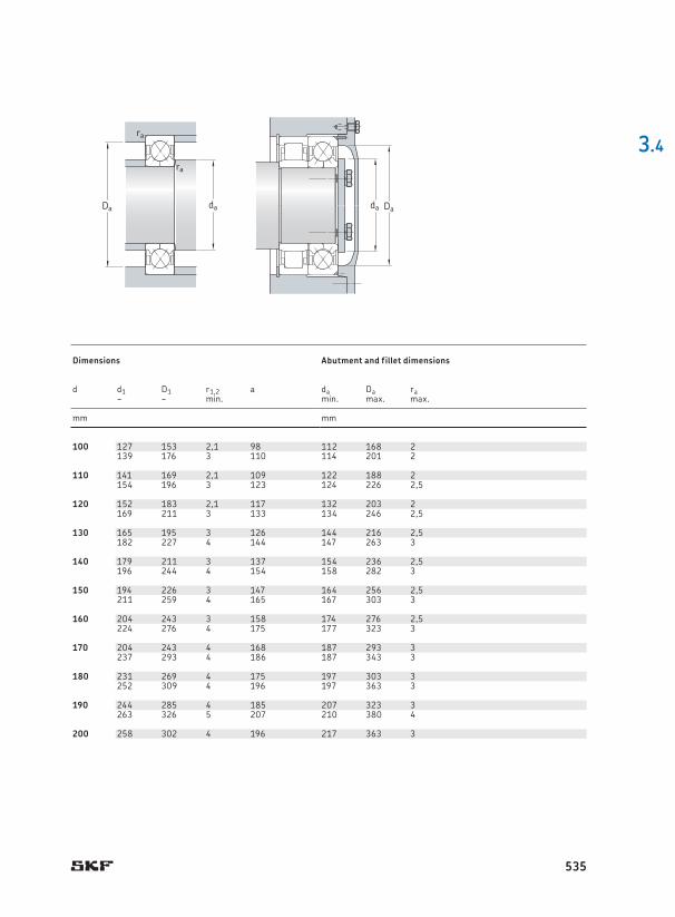
100 180 34 236 265 9,5 4 500 6 300 4,05 * QJ 220 N2MA 100 127 153 2,1 98 112 168 2215 47 345 400 13,7 4 000 5 600 9,3 * QJ 320 N2MA 139 176 3 110 114 201 2
110 200 38 280 325 11,2 4 000 5 600 5,6 * QJ 222 N2MA 110 141 169 2,1 109 122 188 2240 50 390 480 15,3 3 600 4 800 12,5 * QJ 322 N2MA 154 196 3 123 124 226 2,5
120 215 40 300 365 12 3 600 5 000 6,95 * QJ 224 N2MA 120 152 183 2,1 117 132 203 2260 55 415 530 16,3 3 200 4 500 16 * QJ 324 N2MA 169 211 3 133 134 246 2,5
130 230 40 310 400 12,7 3 400 4 800 7,75 * QJ 226 N2MA 130 165 195 3 126 144 216 2,5280 58 455 610 18 3 000 4 000 19,5 * QJ 326 N2MA 182 227 4 144 147 263 3
140 250 42 345 475 14,3 3 200 4 300 9,85 * QJ 228 N2MA 140 179 211 3 137 154 236 2,5300 62 500 695 20 2 800 3 800 24 * QJ 328 N2MA 196 244 4 154 158 282 3
150 270 45 400 570 16,6 3 000 4 000 12,5 * QJ 230 N2MA 150 194 226 3 147 164 256 2,5320 65 530 765 21,2 2 600 3 600 29 * QJ 330 N2MA 211 259 4 165 167 303 3
160 290 48 450 670 19 2 800 3 800 15,5 * QJ 232 N2MA 160 204 243 3 158 174 276 2,5340 68 570 880 23,6 2 400 3 400 34,5 * QJ 332 N2MA 224 276 4 175 177 323 3
170 310 52 455 720 20 2 600 3 400 19,5 * QJ 234 N2MA 170 204 243 4 168 187 293 3360 72 655 1 040 27 2 200 3 200 41,5 * QJ 334 N2MA 237 293 4 186 187 343 3
180 320 52 475 765 20,8 2 400 3 400 20,5 * QJ 236 N2MA 180 231 269 4 175 197 303 3380 75 680 1 100 28 2 200 3 000 47,5 * QJ 336 N2MA 252 309 4 196 197 363 3
190 340 55 510 850 22,4 2 200 3 200 23,5 * QJ 238 N2MA 190 244 285 4 185 207 323 3400 78 702 11 600 28,5 1 700 2 800 49 QJ 338 N2MA 263 326 5 207 210 380 4
200 360 58 540 915 23,2 1 800 3 000 28,5 QJ 240 N2MA 200 258 302 4 196 217 363 3
3.4
da DaDa da
ra
ra
Principal dimensions Basic load ratings Fatigue
load limitSpeed ratings Mass Designation1) Dimensions Abutment and fillet dimensions
dynamic static Reference speed
Limiting speed
Bearing with locating slots2)
d D B C C0 Pu d d1 D1 r1,2 a da Da ra~ ~ min . min . max . max .
mm kN kN r/min kg – mm mm
535