Axial/radial bearings Axial angular contact ball bearings Axial/radial bearings … ·...
82
High Precision Bearings for Combined Loads Axial/radial bearings Axial angular contact ball bearings Axial/radial bearings with angular measuring system
Transcript of Axial/radial bearings Axial angular contact ball bearings Axial/radial bearings … ·...
High Precision Bearingsfor Combined Loads
Axial/radial bearingsAxial angular contact ball bearings
Axial/radial bearings with angular measuring system


Foreword
Focus on complete system With trend-setting bearing arrangement solutions for feed spindles, main spindles, rotary tables and linear guidance units, Schaeffler has been at the forefront of the world market for decades.However, bearing components alone are often no longer the decisive factor for the success of these machine subsystems.Indeed, our customers are continuing to benefit directly from significant performance improvements and unique selling points thanks to our “ready-to-fit” products, since these follow the efficient basic concept: unpack, screw mount, use. In order to optimise the entire machine tool system, however, it is also becoming ever more important to integrate important functions such as measurement, sealing, lubrication, braking etc. in the components themselves. This intellectual approach focusses consistently on the complete system, including the bearing and bearing position. This meansthat you can access a product range that gives optimum coveragefor all your applications in the machine tool.
Direct drives and mechatronicsolutions
In addition, there is increasingly frequent usage of direct drives and mechatronic solutions in machine tools. We therefore have IDAM – INA-Drives & Mechatronics – as a further strong partner in our provider network. In this way, we can supply you from a single source with not only bearing elements but also components precisely matched to the drive system.This opens up completely new technical and economic design possibilities for your requirements as well as significant advantages in the time and process chain.In terms of products, we can offer you a comprehensive, precisely balanced range, precision technology and top product quality.In order to match the pulse of your developments as closely as possible, we also have a worldwide network of engineers and service and sales technicians working for you and ensuring that we maintain close contact with you in your own location.We are therefore confident that we have the right product for you, from a robust individual component right through to the defining high end system solution.
ST4_9007201074084619_vorwort.fm Seite 1 Freitag, 19. August 2016 7:29 07
2 TPI 120 Schaeffler Technologies
High precision bearings for combined loads
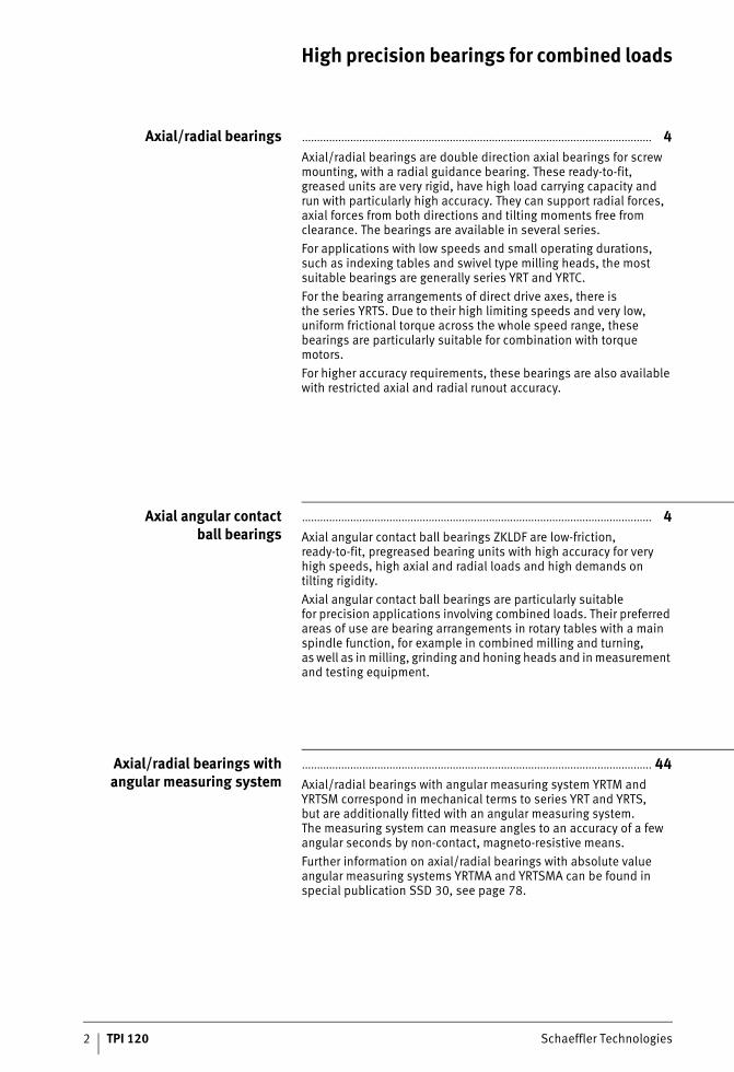
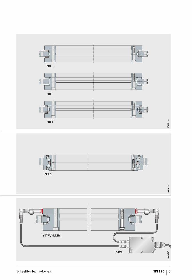
Axial/radial bearings .................................................................................................................... 4Axial/radial bearings are double direction axial bearings for screw mounting, with a radial guidance bearing. These ready-to-fit, greased units are very rigid, have high load carrying capacity andrun with particularly high accuracy. They can support radial forces, axial forces from both directions and tilting moments free from clearance. The bearings are available in several series.For applications with low speeds and small operating durations, such as indexing tables and swivel type milling heads, the most suitable bearings are generally series YRT and YRTC.For the bearing arrangements of direct drive axes, there isthe series YRTS. Due to their high limiting speeds and very low, uniform frictional torque across the whole speed range, these bearings are particularly suitable for combination with torque motors.For higher accuracy requirements, these bearings are also available with restricted axial and radial runout accuracy.
Axial angular contactball bearings
.................................................................................................................... 4Axial angular contact ball bearings ZKLDF are low-friction, ready-to-fit, pregreased bearing units with high accuracy for very high speeds, high axial and radial loads and high demands ontilting rigidity.Axial angular contact ball bearings are particularly suitablefor precision applications involving combined loads. Their preferred areas of use are bearing arrangements in rotary tables with a main spindle function, for example in combined milling and turning,as well as in milling, grinding and honing heads and in measurement and testing equipment.
Axial/radial bearings withangular measuring system
.................................................................................................................... 44Axial/radial bearings with angular measuring system YRTM and YRTSM correspond in mechanical terms to series YRT and YRTS,but are additionally fitted with an angular measuring system.The measuring system can measure angles to an accuracy of a few angular seconds by non-contact, magneto-resistive means.Further information on axial/radial bearings with absolute value angular measuring systems YRTMA and YRTSMA can be found in special publication SSD 30, see page 78.
ST4_9007205160421771_pg_uebers.fm Seite 2 Freitag, 19. August 2016 7:29 07
Schaeffler Technologies TPI 120 3
0009
B104
0009
B104
0009
C82F
0009
C82F
0001
484F
0001
484F
ST4_9007205160421771_pg_uebers.fm Seite 3 Freitag, 19. August 2016 7:29 07
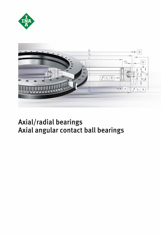
Axial/radial bearingsAxial angular contact ball bearings
ST4_9007205160482699_vorspann.fm Seite 4 Freitag, 19. August 2016 7:30 07

Schaeffler Technologies TPI 120 5
Page
Axial/radial bearings Axial angular contact ball bearings
Product overview Axial/radial bearings, axial angular contact ball bearings........... 6
Features With angular measuring system ................................................. 7
Areas of application................................................................... 7
Axial/radial bearings ................................................................. 8
Axial angular contact ball bearings ............................................ 8
Operating temperature .............................................................. 8
Suffixes..................................................................................... 8
Design andsafety guidelines
General safety guidelines .......................................................... 9
Basic rating life ......................................................................... 10
Static load safety factor ............................................................. 10
Static limiting load diagrams ..................................................... 10
Limiting speeds......................................................................... 14
Temperature distribution in the rotary axis system ..................... 15
Bearing preload......................................................................... 17
Frictional torque ........................................................................ 17
Relubrication and initial operation ............................................. 20
Design of adjacent construction................................................. 22
Fits............................................................................................ 23
L-section ring without support ring or with support ring .............. 27
Improved ease of mounting ....................................................... 30
Fitting........................................................................................ 31
Static rigidity ............................................................................. 32
Accuracy ................................................................................................. 33
Dimension tables Axial/radial bearings, double direction, YRT and YRTC ................ 36
Axial/radial bearings, double direction, YRTS............................. 40
Axial angular contact ball bearings, double direction, ZKLDF ...... 42
ST4_9007205160604171_ivz.fm Seite 5 Freitag, 19. August 2016 7:30 07
6 TPI 120 Schaeffler Technologies
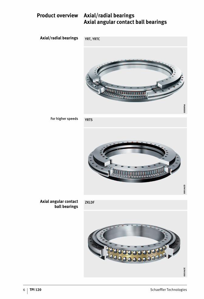
Product overview Axial/radial bearings Axial angular contact ball bearings
Axial/radial bearings YRT, YRTC
0009
AF66
0009
AF66
For higher speeds YRTS
0001
A63D
0001
A63D
Axial angular contactball bearings
ZKLDF
0001
A63E
0001
A63E
ST4_9007205160949387_produktue.fm Seite 6 Freitag, 19. August 2016 7:30 07
Schaeffler Technologies TPI 120 7
Axial/radial bearingsAxial angular contact ball bearings
Features Axial radial bearings YRT, YRTC and YRTS and axial angular contact ball bearings ZKLDF are ready-to-fit high precision bearings forhigh precision applications with combined loads. They can support radial loads, axial loads from both sides and tilting moments without clearance and are particularly suitable for bearing arrangements with high requirements for running accuracy.Due to the fixing holes in the bearing rings, the units are very easyto fit.The bearings are radially and axially preloaded after fitting.The mounting dimensions of all series are identical.Axial/radial bearings YRT in the size range of d = 580 mm to d = 1 030 mm have been replaced by YRTC.Compared with the predecessor product YRT, these bearings have higher rigidity, a higher limiting speed and lower bearing friction.
With angular measuringsystem
Axial/radial bearings are also available with an absolute value angular measuring system or have systems with pitch-coded reference marks. The measuring systems can measure angles toan accuracy of a few angular seconds by non-contact means,see page 44 and page 78.
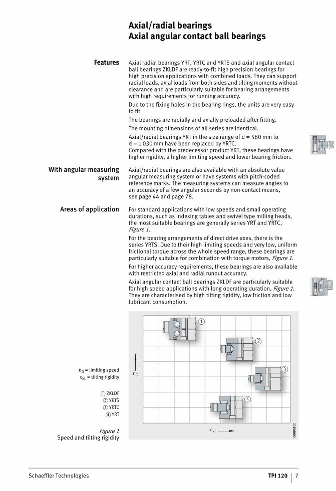
Areas of application For standard applications with low speeds and small operating durations, such as indexing tables and swivel type milling heads,the most suitable bearings are generally series YRT and YRTC,Figure 1.For the bearing arrangements of direct drive axes, there is the series YRTS. Due to their high limiting speeds and very low, uniform frictional torque across the whole speed range, these bearings are particularly suitable for combination with torque motors, Figure 1.For higher accuracy requirements, these bearings are also available with restricted axial and radial runout accuracy.Axial angular contact ball bearings ZKLDF are particularly suitablefor high speed applications with long operating duration, Figure 1. They are characterised by high tilting rigidity, low friction and low lubricant consumption.
nG = limiting speedckL = tilting rigidity
� ZKLDF� YRTS� YRTC
� YRT
Figure 1Speed and tilting rigidity 0009
B10D
0009
B10D
ST4_9007201200419595_beschreib.fm Seite 7 Freitag, 19. August 2016 7:31 07
8 TPI 120 Schaeffler Technologies
Axial/radial bearingsAxial angular contact ball bearings
Axial/radial bearings Axial/radial bearings YRT, YRTC and YRTS have an axial anda radial component.The axial component comprises an axial needle roller or cylindrical roller and cage assembly, an outer ring, L-section ring and shaft locating washer and is axially preloaded after fitting. The radial component is a full complement cylindrical roller set in YRT anda cage-guided, preloaded cylindrical roller set in YRTC and YRTS.The outer ring, L-section ring and shaft locating washer have fixing holes.The unit is located by means of retaining screws for transport and safe handling.
Sealing Axial/radial bearings are supplied without seals.
Lubrication The initial greasing of YRTS corresponds to the grease Arcanol LOAD150 and, in the case of YRT and YRTC, to the grease Arcanol MULTITOP. The bearings can be lubricated via the outer ring and L-section ring.
Axial angular contactball bearings
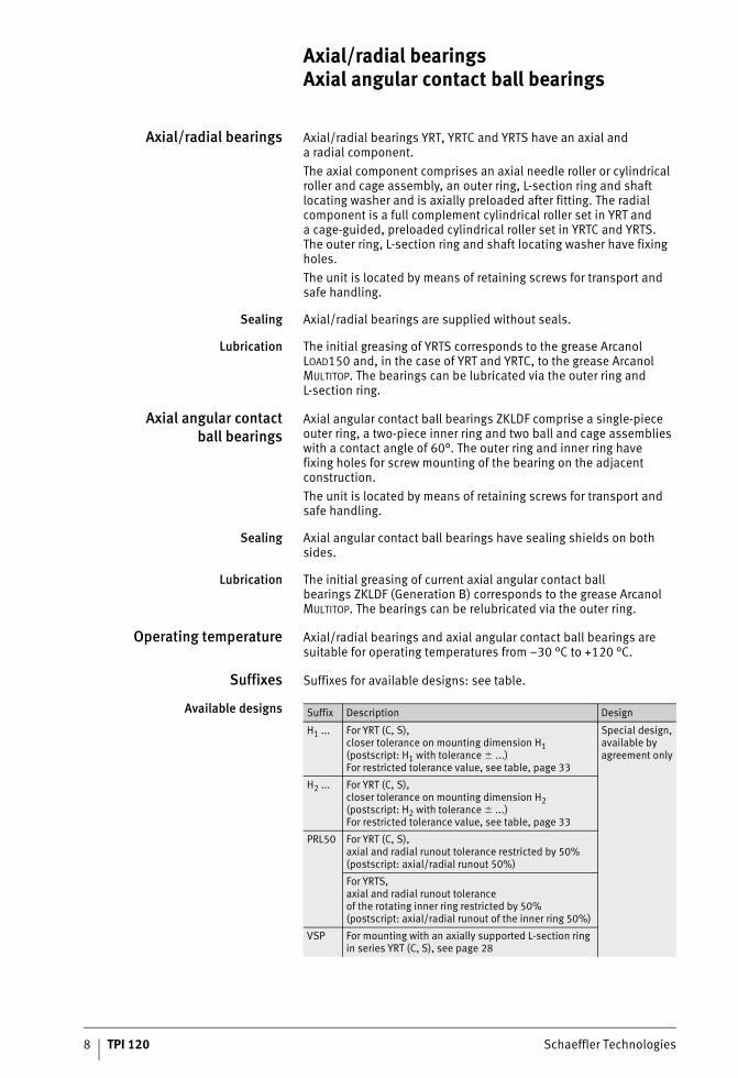
Axial angular contact ball bearings ZKLDF comprise a single-piece outer ring, a two-piece inner ring and two ball and cage assemblies with a contact angle of 60°. The outer ring and inner ring havefixing holes for screw mounting of the bearing on the adjacent construction.The unit is located by means of retaining screws for transport and safe handling.
Sealing Axial angular contact ball bearings have sealing shields on both sides.
Lubrication The initial greasing of current axial angular contact ball bearings ZKLDF (Generation B) corresponds to the grease Arcanol MULTITOP. The bearings can be relubricated via the outer ring.
Operating temperature Axial/radial bearings and axial angular contact ball bearings are suitable for operating temperatures from –30 °C to +120 °C.
Suffixes Suffixes for available designs: see table.
Available designs Suffix Description Design
H1 ... For YRT (C, S),closer tolerance on mounting dimension H1(postscript: H1 with tolerance � ...)For restricted tolerance value, see table, page 33
Special design, available by agreement only
H2 ... For YRT (C, S),closer tolerance on mounting dimension H2(postscript: H2 with tolerance � ...)For restricted tolerance value, see table, page 33
PRL50 For YRT (C, S),axial and radial runout tolerance restricted by 50%(postscript: axial/radial runout 50%)
For YRTS,axial and radial runout toleranceof the rotating inner ring restricted by 50%(postscript: axial/radial runout of the inner ring 50%)
VSP For mounting with an axially supported L-section ring in series YRT (C, S), see page 28
ST4_9007201200419595_beschreib.fm Seite 8 Freitag, 19. August 2016 7:31 07
Schaeffler Technologies TPI 120 9
Design andsafety guidelines
General safety guidelines The general safety guidelines must be observed. Further information relating to safety of control circuits: see Axial/radial bearings with angular measuring system, page 44.
Protection against accidentalcontact (DIN EN 60529)
The guidelines on protection against accidental contactin accordance with DIN EN 60529 must be observed.After fitting, rotating components must be provided with adequate protection against accidential contact in operation.
Usage for the intended purpose The products in this publication are suitable for use in chip-forming machine tools and in particular for the bearing arrangements of high precision rotary axes in milling and turning machines. Any usage outside the specified area or for purposes other than that intended is at at the personal responsibility of the user.Further information relating to bearings with angular measuring system: see page 67.
Modifications to the product Modifications to the product are not permissible and will invalidate the warranty.
Machine safety under the termsof the Machinery Directive
The following rotary table bearings are, under the terms of theMachinery Directive 2006/42/EC, a component for integration in a complete system (finished or unfinished machine). The data and tests given in this publication relate purely to the components and are not a substitute for the detailed tests of the complete system.
Operating time The mean operating time between two failures is described asthe MTBF (Mean Time Between Failure). This can be calculated by agreement for rolling bearings and angular measuring devices.The operating time for rolling bearings is calculated on the basisof the load and speed duty cycle.
ST4_9007201200419595_beschreib.fm Seite 9 Freitag, 19. August 2016 7:31 07
10 TPI 120 Schaeffler Technologies
Axial/radial bearingsAxial angular contact ball bearings
Basic rating life The load carrying capacity and life must be checked for the radial and axial bearing component.Please contact us in relation to checking of the basic rating life.The speed, load and operating duration must be given.
Static load safety factor The static load safety factor S0 indicates the security against impermissible permanent deformations in the bearing:
S0 –Static load safety factorC0r, C0a NBasic static load rating according to dimension tablesF0r, F0a NMaximum static load on the radial or axial bearing.
In machine tools and similar areas of application, S0 should be � 4.
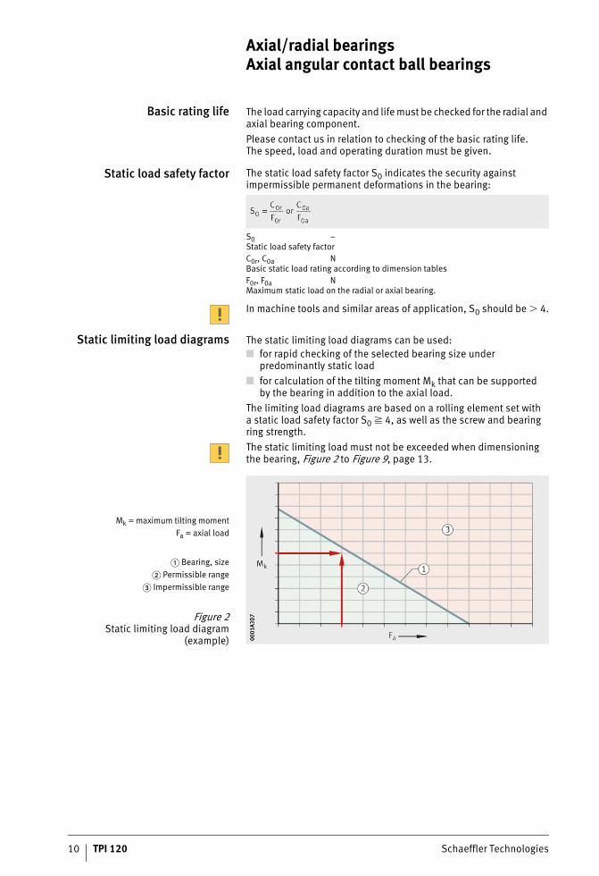
Static limiting load diagrams The static limiting load diagrams can be used:■ for rapid checking of the selected bearing size under
predominantly static load■ for calculation of the tilting moment Mk that can be supported
by the bearing in addition to the axial load.The limiting load diagrams are based on a rolling element set witha static load safety factor S0 � 4, as well as the screw and bearing ring strength.The static limiting load must not be exceeded when dimensioning the bearing, Figure 2 to Figure 9, page 13.
Mk = maximum tilting momentFa = axial load
� Bearing, size� Permissible range
� Impermissible range
Figure 2Static limiting load diagram
(example) 0001
A3D
700
01A3
D7
ST4_9007201200419595_beschreib.fm Seite 10 Freitag, 19. August 2016 7:31 07
Schaeffler Technologies TPI 120 11
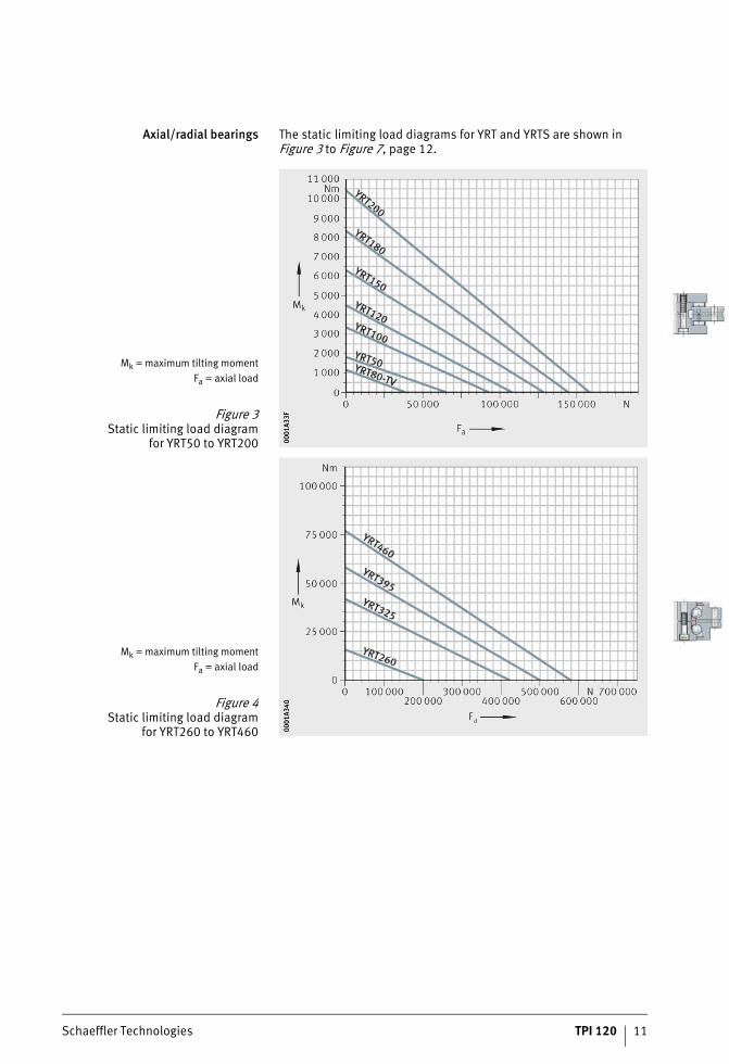
Axial/radial bearings The static limiting load diagrams for YRT and YRTS are shown inFigure 3 to Figure 7, page 12.
Mk = maximum tilting momentFa = axial load
Figure 3Static limiting load diagram
for YRT50 to YRT200 0001
A33F
0001
A33F
Mk = maximum tilting momentFa = axial load
Figure 4Static limiting load diagram
for YRT260 to YRT460 0001
A340
0001
A340
ST4_9007201200419595_beschreib.fm Seite 11 Freitag, 19. August 2016 7:31 07
12 TPI 120 Schaeffler Technologies
Axial/radial bearingsAxial angular contact ball bearings
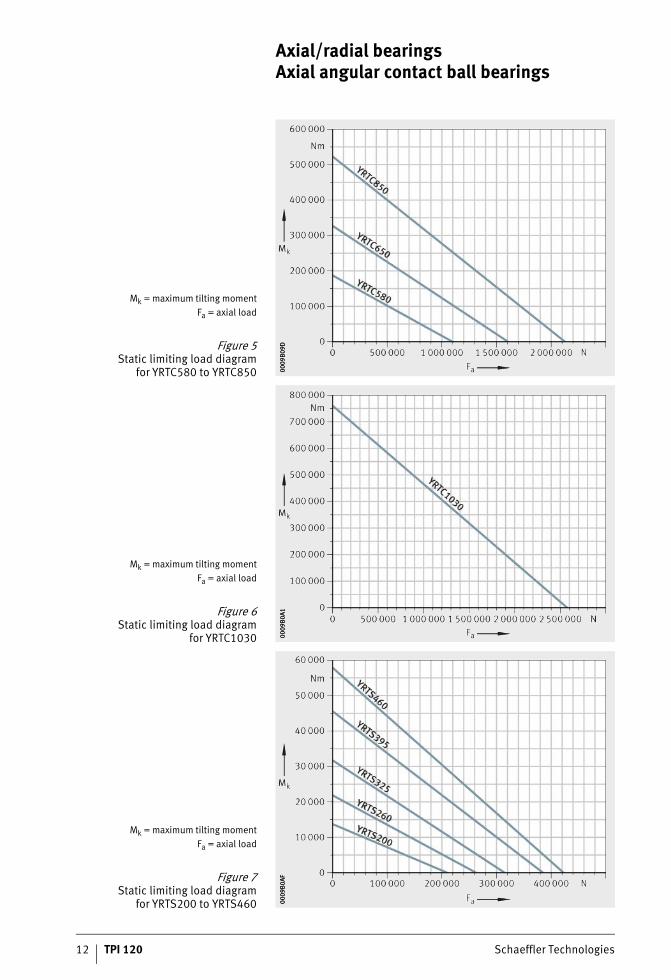
Mk = maximum tilting momentFa = axial load
Figure 5Static limiting load diagram
for YRTC580 to YRTC850 0009
B09D
0009
B09D
Mk = maximum tilting momentFa = axial load
Figure 6Static limiting load diagram
for YRTC1030 0009
B0A1
0009
B0A1
Mk = maximum tilting momentFa = axial load
Figure 7Static limiting load diagram
for YRTS200 to YRTS460 0009
B0AF
0009
B0AF
ST4_9007201200419595_beschreib.fm Seite 12 Freitag, 19. August 2016 7:32 07
Schaeffler Technologies TPI 120 13
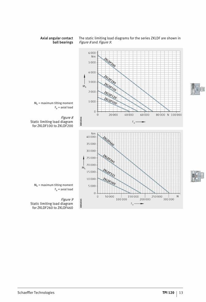
Axial angular contactball bearings
The static limiting load diagrams for the series ZKLDF are shown in Figure 8 and Figure 9.
Mk = maximum tilting momentFa = axial load
Figure 8Static limiting load diagram
for ZKLDF100 to ZKLDF200 0001
A344
0001
A344
Mk = maximum tilting momentFa = axial load
Figure 9Static limiting load diagram
for ZKLDF260 to ZKLDF460 0001
A345
0001
A345
ST4_9007201200419595_beschreib.fm Seite 13 Freitag, 19. August 2016 7:32 07
14 TPI 120 Schaeffler Technologies
Axial/radial bearingsAxial angular contact ball bearings
Limiting speeds In bearing selection, the following guidelines and the limiting speeds must be observed, see dimension tables.If the environmental conditions differ from the specificationsin relation to adjacent construction tolerances, lubrication, ambient temperature, heat dissipation or from the normal operating conditions for machine tools, the stated limiting speeds must be checked. Please contact us.
Axial/radial bearing YRT Axial/radial bearings YRT are designed, by means of the full complement radial roller bearing component for high rigidity,for rapid positioning and operating at low speed. Low speeds are normally required for multiple-axis simultaneous machining.The limit value nG stated in the dimension tables relates tothe maximum swivel speed and a maximum speed applied fora short period. In applications with a high operating duration ED or continuous operation at a speed of more than n�d = 35 000 min–1 · mmat an ED � 10%, the series YRTS or ZKLDF should be selected.
Axial radial bearings YRTC, YRTSand axial angular contact
ball bearings ZKLDF
The limiting speeds nG stated for these bearing series were determined on test rigs.During the test, the following conditions apply:■ grease distribution cycle according to the defined data,
see Figure 15, page 21■ maximum increase in bearing temperature of 40 K in the area
of the raceway■ operating duration ED = 100%, which means continuous
operation at the limiting speed nG■ bearing fully screw mounted on solid fixtures■ no external load, only preload and mass of the fixtures.
ST4_9007201200419595_beschreib.fm Seite 14 Freitag, 19. August 2016 7:32 07
Schaeffler Technologies TPI 120 15
Temperature distributionin the rotary axis system
Rotary axes with a main spindle function, such as those usedfor combined milling and turning and with direct drive by a torque motor, are systems with complex thermal characteristics.The temperature distribution in the rotary axis system must be considered in greater detail during the design process:■ Asymmetrical rotary axis housings can undergo asymmetrical
deformation due to heating.■ In turn, out-of-round bearing seats lead to additional bearing
load, reduced life and a negative influence on running behaviour and running accuracy.
■ Temperature management of the rotary axis in the formof targeted cooling and heating is generally necessary for high performance rotary axes. For simulation work, the Schaeffler Group has high performance simulation tools available.
Where there is non-uniform temperature distribution betweenthe inner and outer ring, rotary axis bearings with ball contact (ZKLDF) show more tolerant behaviour than rotary axis bearings with line contact (such as axial/radial cylindrical roller bearings or crossed roller bearings).The stated bearing characteristics only apply if the bearingpreload remains unchanged. The bearing preload can be alteredby mechanical stresses, such as those which can be caused by temperature differences or adjacent machine elements (such as force-locking clamping connections for example).
ST4_9007201200419595_beschreib.fm Seite 15 Freitag, 19. August 2016 7:32 07
16 TPI 120 Schaeffler Technologies
Axial/radial bearingsAxial angular contact ball bearings
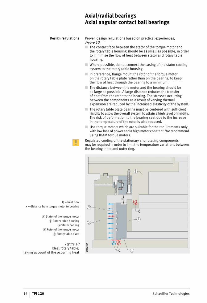
Design regulations Proven design regulations based on practical experiences, Figure 10:■ The contact face between the stator of the torque motor and
the rotary table housing should be as small as possible, in order to minimise the flow of heat between stator and rotary table housing.
■ Where possible, do not connect the casing of the stator cooling system to the rotary table housing.
■ In preference, flange mount the rotor of the torque motoron the rotary table plate rather than on the bearing, to keepthe flow of heat through the bearing to a minimum.
■ The distance between the motor and the bearing should beas large as possible. A large distance reduces the transferof heat from the rotor to the bearing. The stresses occurringbetween the components as a result of varying thermalexpansion are reduced by the increased elasticity of the system.
■ The rotary table plate bearing must be centered with sufficient rigidity to allow the overall system to attain a high level of rigidity. The risk of deformation to the bearing seat due to the increasein the temperature of the rotor is also reduced.
■ Use torque motors which are suitable for the requirements only,with low loss of power and a high motor constant. We recommend using IDAM torque motors.
Regulated cooling of the stationary and rotating componentsmay be required in order to limit the temperature variations between the bearing inner and outer ring.
Q = heat flowx = distance from torque motor to bearing
� Stator of the torque motor� Rotary table housing
� Stator cooling� Rotor of the torque motor
� Rotary table plate
Figure 10Ideal rotary table,
taking account of the occurring heat 0001
A2D
B00
01A2
DB
ST4_9007201200419595_beschreib.fm Seite 16 Freitag, 19. August 2016 7:32 07
Schaeffler Technologies TPI 120 17
Bearing preload Once the bearings have been fitted and fully screw mounted,they are radially and axially clearance-free and preloaded.
Temperature differences Temperature differences between the shaft and housing influence the radial bearing preload and thus the operating behaviour and operating life of the bearing arrangement.If the shaft temperature is higher than the housing temperature,the radial preload will increase proportionally, so there will bean increase in the rolling element load, bearing friction and bearing temperature, while the operating life will be reduced.If the shaft temperature is lower than the housing temperature,the radial preload will decrease proportionally, so the rigidity will decrease to bearing clearance. There will be an increase in wear,the operating life will be reduced and noise due to slippage may occur.
Frictional torque The bearing frictional torque MR is influenced primarily bythe viscosity and quantity of the lubricant and the bearing preload:■ The lubricant viscosity is dependent on the lubricant grade and
operating temperature.■ When relubrication is carried out, the lubricant quantity is
increased for a short time until the grease is distributed andthe excess quantity has left the bearing.
■ During initial operation and after relubrication, bearing frictionis increased until the lubricant has been distributed withinthe bearing.
■ The bearing preload is dependent on the mounting fits,the geometrical accuracy of the adjacent parts, the temperature difference between the inner and outer ring, the screw tightening torque and mounting situation (bearing inner ring axially supported on one or both sides).
In the case of series YRT, the bearing frictional torque is heavily influenced by the tightening torque of the inner ring fixing screws.As a result, the preload in the axial bearing parts can be increased by using screws of grade 12.9 and the corresponding tightening torque if required.If a lower frictional torque is to be achieved, this can, for example,be realised by reducing the screw tightening torque. As the self-locking function of the screw connection which secures against loosening is also reduced as a result, the screws must be secured using suitable thread lockers.For applications which are sensitive to frictional torque,we recommend using series ZKLDF or YRTS.
ST4_9007201200419595_beschreib.fm Seite 17 Freitag, 19. August 2016 7:32 07
18 TPI 120 Schaeffler Technologies
Axial/radial bearingsAxial angular contact ball bearings
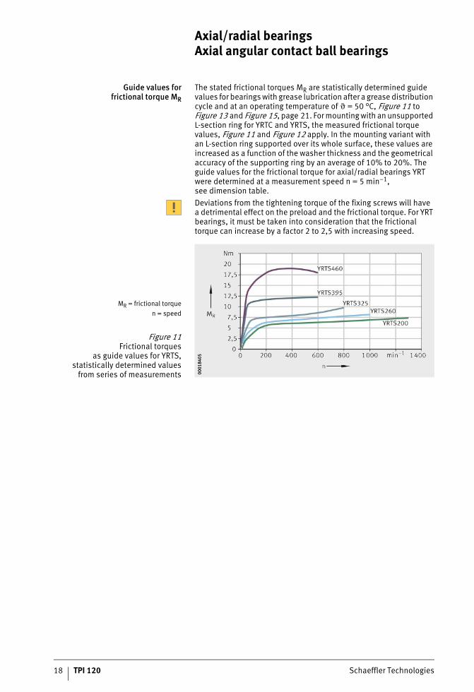
Guide values forfrictional torque MR
The stated frictional torques MR are statistically determined guide values for bearings with grease lubrication after a grease distribution cycle and at an operating temperature of � = 50 °C, Figure 11 to Figure 13 and Figure 15, page 21. For mounting with an unsupported L-section ring for YRTC and YRTS, the measured frictional torque values, Figure 11 and Figure 12 apply. In the mounting variant with an L-section ring supported over its whole surface, these values are increased as a function of the washer thickness and the geometrical accuracy of the supporting ring by an average of 10% to 20%. The guide values for the frictional torque for axial/radial bearings YRT were determined at a measurement speed n = 5 min–1,see dimension table. Deviations from the tightening torque of the fixing screws will havea detrimental effect on the preload and the frictional torque. For YRT bearings, it must be taken into consideration that the frictional torque can increase by a factor 2 to 2,5 with increasing speed.
MR = frictional torquen = speed
Figure 11Frictional torques
as guide values for YRTS,statistically determined values
from series of measurements 0001
8405
0001
8405
ST4_9007201200419595_beschreib.fm Seite 18 Freitag, 19. August 2016 7:32 07
Schaeffler Technologies TPI 120 19
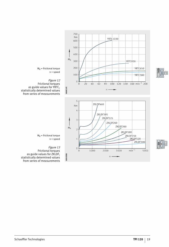
MR = frictional torquen = speed
Figure 12Frictional torques
as guide values for YRTC,statistically determined values
from series of measurements 0009
C1FE
0009
C1FE
MR = frictional torquen = speed
Figure 13Frictional torques
as guide values for ZKLDF,statistically determined values
from series of measurements 0001
83B0
0001
83B0
ST4_9007201200419595_beschreib.fm Seite 19 Freitag, 19. August 2016 7:33 07
20 TPI 120 Schaeffler Technologies
Axial/radial bearingsAxial angular contact ball bearings
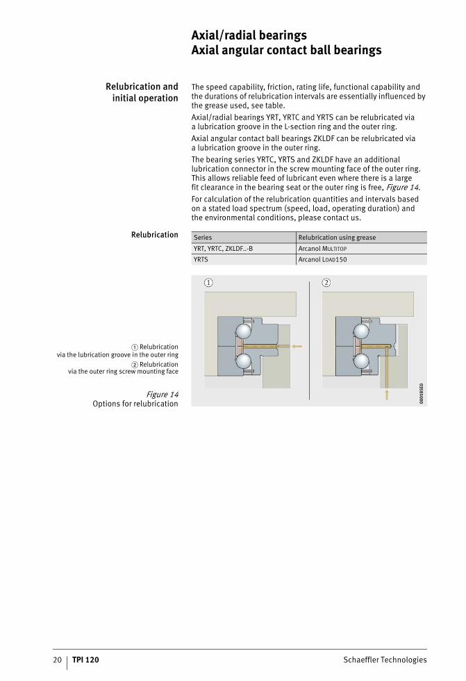
Relubrication andinitial operation
The speed capability, friction, rating life, functional capability and the durations of relubrication intervals are essentially influenced by the grease used, see table.Axial/radial bearings YRT, YRTC and YRTS can be relubricated viaa lubrication groove in the L-section ring and the outer ring.Axial angular contact ball bearings ZKLDF can be relubricated viaa lubrication groove in the outer ring.The bearing series YRTC, YRTS and ZKLDF have an additional lubrication connector in the screw mounting face of the outer ring. This allows reliable feed of lubricant even where there is a largefit clearance in the bearing seat or the outer ring is free, Figure 14.For calculation of the relubrication quantities and intervals basedon a stated load spectrum (speed, load, operating duration) andthe environmental conditions, please contact us.
Relubrication Series Relubrication using grease
YRT, YRTC, ZKLDF..-B Arcanol MULTITOP
YRTS Arcanol LOAD150
� Relubricationvia the lubrication groove in the outer ring
� Relubricationvia the outer ring screw mounting face
Figure 14Options for relubrication 00
0185
E000
0185
E0
ST4_9007201200419595_beschreib.fm Seite 20 Freitag, 19. August 2016 7:33 07
Schaeffler Technologies TPI 120 21
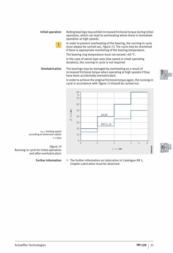
Initial operation Rolling bearings may exhibit increased frictional torque during initial operation, which can lead to overheating where there is immediate operation at high speeds.In order to prevent overheating of the bearing, the running-in cycle must always be carried out, Figure 15. The cycle may be shortenedif there is appropriate monitoring of the bearing temperature.The bearing ring temperature must not exceed +60 °C.In the case of swivel type axes (low speed or small operating duration), the running-in cycle is not required.
Overlubrication The bearings may be damaged by overheating as a result of increased frictional torque when operating at high speeds if they have been accidentally overlubricated.In order to achieve the original frictional torque again, the running-in cycle in accordance with Figure 15 should be carried out.
Further information ■ The further information on lubrication in Catalogue HR 1,chapter Lubrication must be observed.
nG = limiting speedaccording to dimension tables
t = time
Figure 15Running-in cycle for initial operation
and after overlubrication 0009
C838
0009
C838
ST4_9007201200419595_beschreib.fm Seite 21 Freitag, 19. August 2016 7:33 07
22 TPI 120 Schaeffler Technologies
Axial/radial bearingsAxial angular contact ball bearings
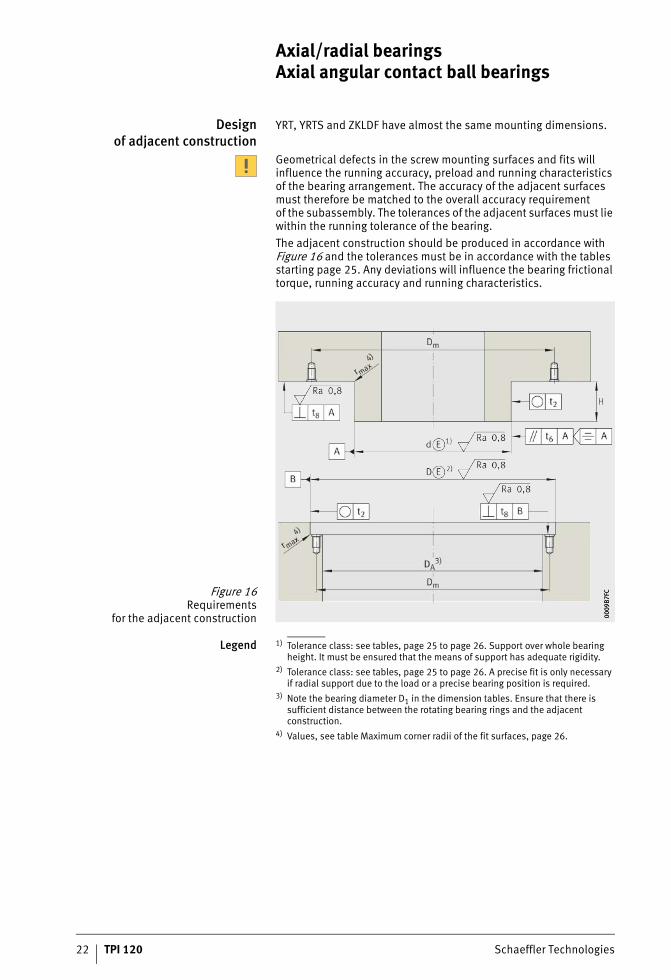
Designof adjacent construction
YRT, YRTS and ZKLDF have almost the same mounting dimensions.
Geometrical defects in the screw mounting surfaces and fits will influence the running accuracy, preload and running characteristics of the bearing arrangement. The accuracy of the adjacent surfaces must therefore be matched to the overall accuracy requirementof the subassembly. The tolerances of the adjacent surfaces must lie within the running tolerance of the bearing.The adjacent construction should be produced in accordance with Figure 16 and the tolerances must be in accordance with the tables starting page 25. Any deviations will influence the bearing frictional torque, running accuracy and running characteristics.
Legend 1) Tolerance class: see tables, page 25 to page 26. Support over whole bearing height. It must be ensured that the means of support has adequate rigidity.
2) Tolerance class: see tables, page 25 to page 26. A precise fit is only necessary if radial support due to the load or a precise bearing position is required.
3) Note the bearing diameter D1 in the dimension tables. Ensure that there is sufficient distance between the rotating bearing rings and the adjacent construction.
4) Values, see table Maximum corner radii of the fit surfaces, page 26.
Figure 16Requirements
for the adjacent construction 0009
B7FC
0009
B7FC
ST4_9007201200419595_beschreib.fm Seite 22 Freitag, 19. August 2016 7:33 07
Schaeffler Technologies TPI 120 23
Fits The selection of fits leads to transition fits, i.e. depending on the actual dimensional position of the bearing diameter and mounting dimensions, clearance fits or interference fits can arise.The fit influences, for example, the running accuracy of the bearing and its dynamic characteristics.An excessively tight fit will increase the radial bearing preload.As a result:■ there is an increase in bearing friction and heat generation in
the bearing as well as the load on the raceway system and wear■ there will be a decrease in the achievable speed and the bearing
operating life.For easier matching of the adjacent construction to the actual bearing dimensions, each bearing of series YRT and YRTS is supplied with a measurement record (this is available by agreement for other series).
Axial and radialrunout accuracy
of the bearing arrangement
The axial and radial runout accuracy is influenced by:■ the running accuracy of the bearing■ the geometrical accuracy of the adjacent surfaces■ the fit between the rotating bearing ring and adjacent
component.For very high running accuracy, the rotating bearing ring should ideally have a fit clearance 0 and it should be ensured thatthe bearing has preload in operation, see page 17.
Recommended fitsfor shafts
The shaft should be produced to tolerance class h5e andfor series YRTS in accordance with table, page 26.If there are special requirements, the fit clearance must be further restricted within the stated tolerance classes:■ Requirements for running accuracy:
For maximum running accuracy and with a rotating bearing inner ring, the aim should be to achieve as close as possible to a fit clearance 0. The fit clearance may otherwise increase the bearing radial runout. With normal requirements for running accuracy or a stationary bearing inner ring, the shaft for series YRT, YRTC and ZKLDF should be produced to h5 e. For axial/radial bearing YRTS, the recommended fits for shaft and housing bore must be observed, see table, page 26.
■ Requirements for dynamic characteristics:– For swivel type operation (n�d � 35 000 min–1 · mm,
operating duration ED � 10%) the shaft should be producedto h5 e. The tolerance class h5 e can be used under these operating conditions for series YRT, YRTC, YRTS and ZKLDF.
– For higher speeds and longer operating duration,the fit interference must not exceed 0,01 mm.For series YRTS, the fit interference must not exceed 0,005 mm.
For series ZKLDF, the fit clearance should be based on the inner ring with the smallest bore dimension.
ST4_9007201200419595_beschreib.fm Seite 23 Freitag, 19. August 2016 7:33 07
24 TPI 120 Schaeffler Technologies
Axial/radial bearingsAxial angular contact ball bearings
Recommended fitsfor housings
The housing should be produced to tolerance class J6e andfor series YRTS in accordance with table Recommended fits for shaft and housing bore for YRTS, page 26.If there are special requirements, the fit clearance must be further restricted within the stated tolerance classes:■ Requirements for running accuracy:
For maximum running accuracy and with a rotating bearing outer ring, the aim should be to achieve as close as possible to a fit clearance of 0. With a static bearing outer ring, a clearance fit or a design without radial centring should be selected.
■ Requirements for dynamic characteristics:– For predominantly swivel type operation
(n�d � 35 000 min–1 · mm, operating duration ED � 10%) and a rotating bearing outer ring, the housing fit should be produced to tolerance class J6e. The tolerance class J6ecan be used under these operating conditions for series YRT, YRTC, YRTS and ZKLDF.
– For axial/radial bearing YRTS with a higher speed and operat-ing duration, a thermal FE calculation of the subassembly must be carried out.
If the calculations show a higher temperature at the shaft and bearing inner ring than at the bearing outer ring, it may be advantageous not to centre the bearing outer ring radially or to produce the housing fit as a clearance fit with at least 0,02 mm clearance. This will reduce the increase in preload that occurs where there is a temperature differential between the inner ring andouter ring of the bearing. However, if the temperature differential is too great, this may lead to overloading of the screw connections of the outer ring and the screw connection will start to slip. The result of this is radial clearance in the bearing arrangement of a cold machine.If the calculations at the bearing outer ring show an identical or higher temperature in relation to the inner ring, then the housing should be produced in accordance with the recommended fits for shaft and housing bore for YRTS, see table, page 26.
Fit selection dependingon the screw connection
of the bearing rings
If the bearing outer ring is screw mounted on the static component, a fit seating is not required or a fit seating can be produced as stated, see tables, page 25 to page 26. If the values in the table are used, this will give a transition fit with a tendency towards clearance fit. This generally allows easy fitting.If the bearing inner ring is screw mounted on the static component, it should nevertheless for functional reasons be supported bythe shaft over the whole bearing height. The shaft dimensions should then be selected accordingly, see tables, page 25 to page 26. If these values in the table are used, this will give a transition fit with a tendency towards clearance fit.
ST4_9007201200419595_beschreib.fm Seite 24 Freitag, 19. August 2016 7:33 07
Schaeffler Technologies TPI 120 25
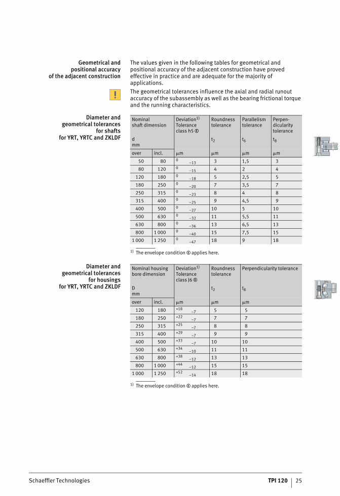
Geometrical andpositional accuracy
of the adjacent construction
The values given in the following tables for geometrical and positional accuracy of the adjacent construction have proved effective in practice and are adequate for the majority of applications.The geometrical tolerances influence the axial and radial runout accuracy of the subassembly as well as the bearing frictional torque and the running characteristics.
Diameter andgeometrical tolerances
for shaftsfor YRT, YRTC and ZKLDF
1) The envelope condition e applies here.
Diameter andgeometrical tolerances
for housingsfor YRT, YRTC and ZKLDF
1) The envelope condition e applies here.
Nominalshaft dimension
Deviation1)
Toleranceclass h5e
Roundness tolerance
Parallelism tolerance
Perpen-dicularity tolerance
dmm
t2 t6 t8
over incl. �m �m �m �m
50 80 0–13 3 1,5 3
80 120 0–15 4 2 4
120 180 0–18 5 2,5 5
180 250 0–20 7 3,5 7
250 315 0–23 8 4 8
315 400 0–25 9 4,5 9
400 500 0–27 10 5 10
500 630 0–32 11 5,5 11
630 800 0–36 13 6,5 13
800 1 000 0–40 15 7,5 15
1 000 1 250 0–47 18 9 18
Nominal housing bore dimension
Deviation1)
Tolerance class J6e
Roundness tolerance
Perpendicularity tolerance
Dmm
t2 t8
over incl. �m �m �m
120 180 +18–7 5 5
180 250 +22–7 7 7
250 315 +25–7 8 8
315 400 +29–7 9 9
400 500 +33–7 10 10
500 630 +34–10 11 11
630 800 +38–12 13 13
800 1 000 +44–12 15 15
1 000 1 250 +52–14 18 18
ST4_9007201200419595_beschreib.fm Seite 25 Freitag, 19. August 2016 7:33 07
26 TPI 120 Schaeffler Technologies
Axial/radial bearingsAxial angular contact ball bearings
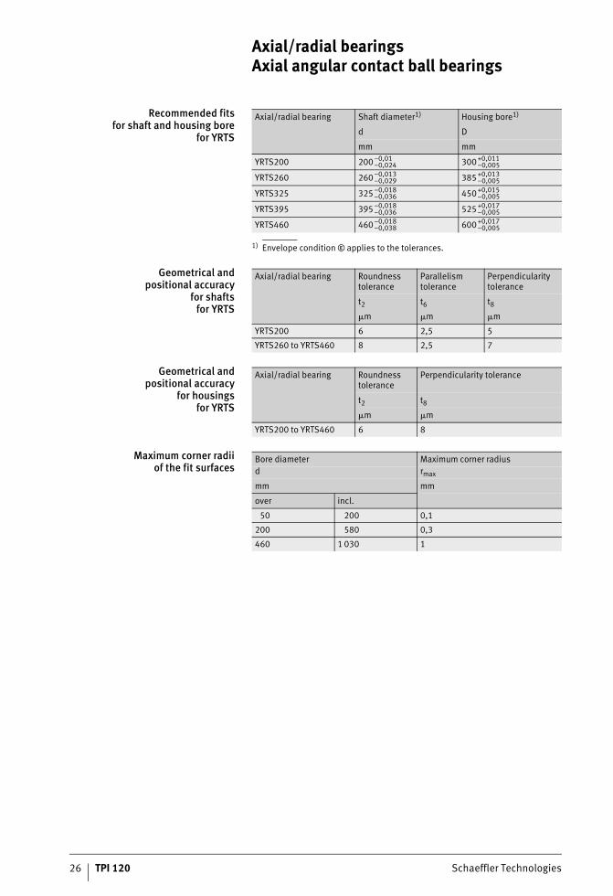
Recommended fitsfor shaft and housing bore
for YRTS
1) Envelope conditione applies to the tolerances.
Geometrical andpositional accuracy
for shaftsfor YRTS
Geometrical andpositional accuracy
for housingsfor YRTS
Maximum corner radiiof the fit surfaces
Axial/radial bearing Shaft diameter1) Housing bore1)
d D
mm mm
YRTS200 200–0,01–0,024 300+0,011
–0,005
YRTS260 260–0,013–0,029 385+0,013
–0,005
YRTS325 325–0,018–0,036 450+0,015
–0,005
YRTS395 395–0,018–0,036 525+0,017
–0,005
YRTS460 460–0,018–0,038 600+0,017
–0,005
Axial/radial bearing Roundness tolerance
Parallelism tolerance
Perpendicularity tolerance
t2 t6 t8
�m �m �m
YRTS200 6 2,5 5
YRTS260 to YRTS460 8 2,5 7
Axial/radial bearing Roundness tolerance
Perpendicularity tolerance
t2 t8
�m �m
YRTS200 to YRTS460 6 8
Bore diameter Maximum corner radiusd rmax
mm mm
over incl.
50 200 0,1
200 580 0,3
460 1 030 1
ST4_9007201200419595_beschreib.fm Seite 26 Freitag, 19. August 2016 7:33 07
Schaeffler Technologies TPI 120 27
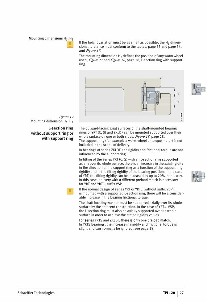
Mounting dimensions H1, H2If the height variation must be as small as possible, the H1 dimen-sional tolerance must conform to the tables, page 33 and page 34,and Figure 17.The mounting dimension H2 defines the position of any worm wheel used, Figure 17 and Figure 18, page 28, L-section ring with support ring.
L-section ringwithout support ring or
with support ring
The outward-facing axial surfaces of the shaft-mounted bearingrings of YRT (C, S) and ZKLDF can be mounted supported over their whole surface on one or both sides, Figure 18, page 28.The support ring (for example a worm wheel or torque motor) is not included in the scope of delivery.In bearings of series ZKLDF, the rigidity and frictional torque are not influenced by the support ring.In fitting of the series YRT (C, S) with an L-section ring supported axially over its whole surface, there is an increase in the axial rigidity in the direction of the support ring as a function of the support ring rigidity and in the tilting rigidity of the bearing position. In the case of YRT, the tilting rigidity can be increased by up to 20% in this way. In this case, delivery with a different preload match is necessaryfor YRT and YRTC, suffix VSP.If the normal design of series YRT or YRTC (without suffix VSP)is mounted with a supported L-section ring, there will be a consider-able increase in the bearing frictional torque.The shaft locating washer must be supported axially over its whole surface by the adjacent construction. In the case of YRT..- VSP,the L-section ring must also be axially supported over its whole surface in order to achieve the stated rigidity values.For series YRTS and ZKLDF, there is only one preload match.In YRTS bearings, the increase in rigidity and frictional torque is slight and can normally be ignored, see page 18.
Figure 17Mounting dimension H1, H2
107
322A
107
322A
28 TPI 120 Schaeffler Technologies
Axial/radial bearingsAxial angular contact ball bearings
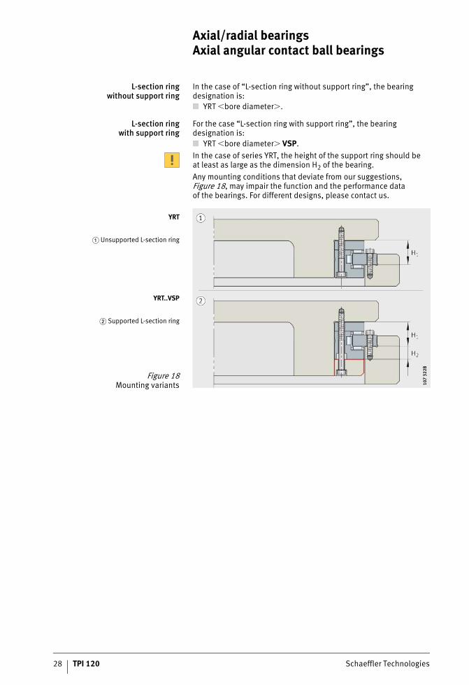
L-section ringwithout support ring
In the case of “L-section ring without support ring”, the bearing designation is:■ YRT �bore diameter�.
L-section ring with support ring
For the case “L-section ring with support ring”, the bearingdesignation is:■ YRT �bore diameter� VSP.In the case of series YRT, the height of the support ring should beat least as large as the dimension H2 of the bearing.Any mounting conditions that deviate from our suggestions, Figure 18, may impair the function and the performance dataof the bearings. For different designs, please contact us.
YRT
� Unsupported L-section ring
YRT..VSP
� Supported L-section ring
Figure 18Mounting variants 10
7 32
2B10
7 32
2B
ST4_9007201200419595_beschreib.fm Seite 28 Freitag, 19. August 2016 7:34 07
Schaeffler Technologies TPI 120 29
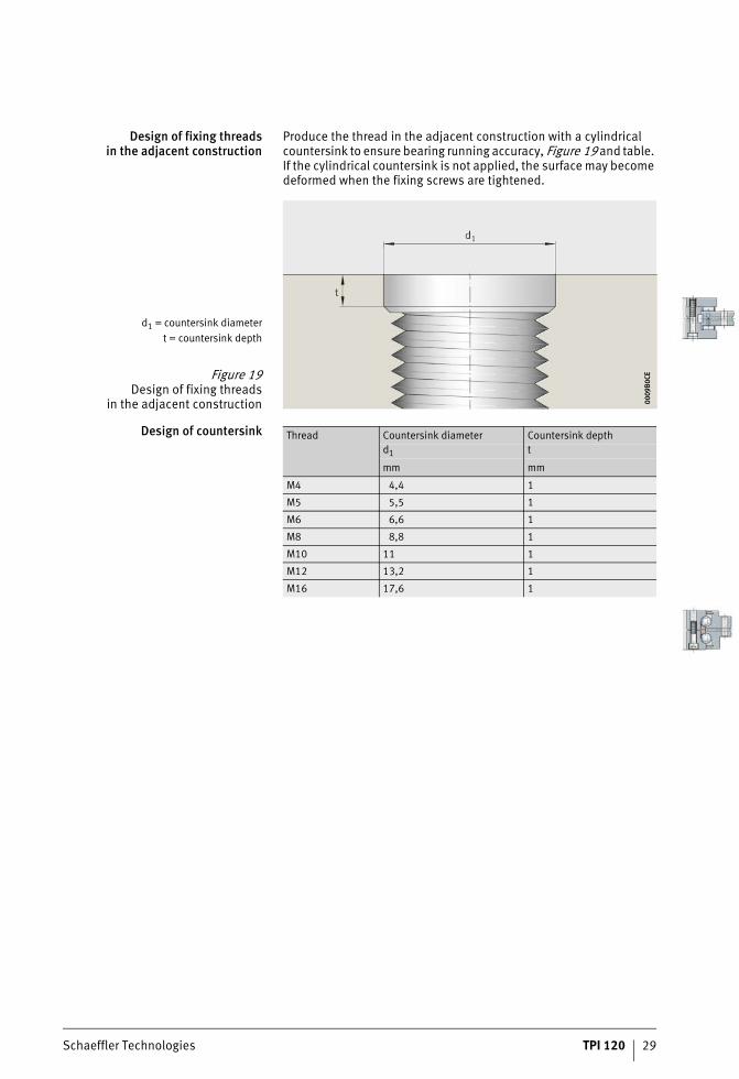
Design of fixing threadsin the adjacent construction
Produce the thread in the adjacent construction with a cylindrical countersink to ensure bearing running accuracy, Figure 19 and table. If the cylindrical countersink is not applied, the surface may become deformed when the fixing screws are tightened.
Design of countersink
d1 = countersink diametert = countersink depth
Figure 19Design of fixing threads
in the adjacent construction 0009
B0CE
0009
B0CE
Thread Countersink diameter Countersink depthd1 t
mm mm
M4 4,4 1
M5 5,5 1
M6 6,6 1
M8 8,8 1
M10 11 1
M12 13,2 1
M16 17,6 1
ST4_9007201200419595_beschreib.fm Seite 29 Freitag, 19. August 2016 7:34 07
30 TPI 120 Schaeffler Technologies
Axial/radial bearingsAxial angular contact ball bearings
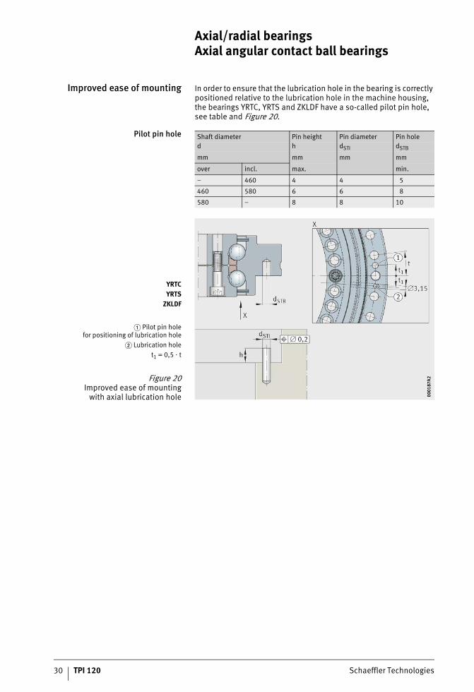
Improved ease of mounting In order to ensure that the lubrication hole in the bearing is correctly positioned relative to the lubrication hole in the machine housing, the bearings YRTC, YRTS and ZKLDF have a so-called pilot pin hole, see table and Figure 20.
Pilot pin hole Shaft diameter Pin height Pin diameter Pin holed h dSTI dSTB
mm mm mm mm
over incl. max. min.
– 460 4 4 5
460 580 6 6 8
580 – 8 8 10
YRTCYRTS
ZKLDF
� Pilot pin holefor positioning of lubrication hole
� Lubrication holet1 = 0,5 � t
Figure 20Improved ease of mounting
with axial lubrication hole 0001
87A2
0001
87A2
ST4_9007201200419595_beschreib.fm Seite 30 Freitag, 19. August 2016 7:34 07
Schaeffler Technologies TPI 120 31
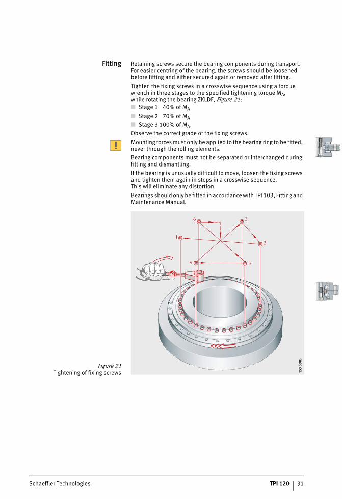
Fitting Retaining screws secure the bearing components during transport. For easier centring of the bearing, the screws should be loosened before fitting and either secured again or removed after fitting.Tighten the fixing screws in a crosswise sequence using a torque wrench in three stages to the specified tightening torque MA,while rotating the bearing ZKLDF, Figure 21:■ Stage 1 40% of MA■ Stage 2 70% of MA■ Stage 3 100% of MA.Observe the correct grade of the fixing screws.Mounting forces must only be applied to the bearing ring to be fitted, never through the rolling elements.Bearing components must not be separated or interchanged during fitting and dismantling.If the bearing is unusually difficult to move, loosen the fixing screws and tighten them again in steps in a crosswise sequence.This will eliminate any distortion.Bearings should only be fitted in accordance with TPI 103, Fitting and Maintenance Manual.
Figure 21Tightening of fixing screws 15
3 06
8B15
3 06
8B
ST4_9007201200419595_beschreib.fm Seite 31 Freitag, 19. August 2016 7:34 07
32 TPI 120 Schaeffler Technologies
Axial/radial bearingsAxial angular contact ball bearings
Static rigidity The overall rigidity of a bearing position is a description of the magnitude of the displacement of the rotational axis from its ideal position under load. The static rigidity thus has a direct influenceon the accuracy of the machining results.The dimension tables give the rigidity values for the complete bearing position, see page 36 to page 43. These take account of the deflection of the rolling element set as well as the deformation of the bearing rings and the screw connections.The values for the rolling element sets are calculated rigidity values and are for information purposes only. They facilitate comparison with other bearing types, since rolling bearing catalogues generally only give the higher rigidity values for the rolling element set.In the case of series YRT and YRTS, the axial rigidity in the corresponding direction and the tilting rigidity can be increasedby supporting the L-section ring over its whole surface. The tilting rigidity is increased by up to 20% as a function of the thicknessof the support washer.
ST4_9007201200419595_beschreib.fm Seite 32 Freitag, 19. August 2016 7:34 07
Schaeffler Technologies TPI 120 33
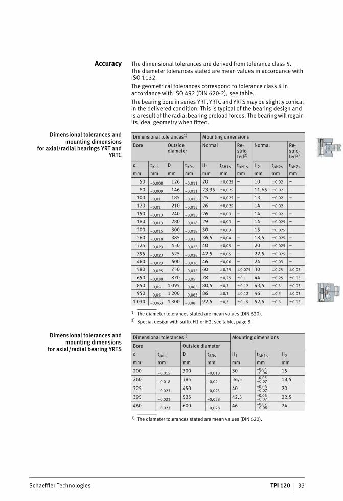
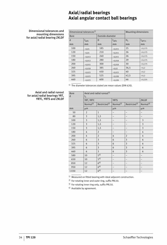
Accuracy The dimensional tolerances are derived from tolerance class 5.The diameter tolerances stated are mean values in accordance with ISO 1132.The geometrical tolerances correspond to tolerance class 4 in accordance with ISO 492 (DIN 620-2), see table.The bearing bore in series YRT, YRTC and YRTS may be slightly conical in the delivered condition. This is typical of the bearing design and is a result of the radial bearing preload forces. The bearing will regain its ideal geometry when fitted.
Dimensional tolerances andmounting dimensions
for axial/radial bearings YRT andYRTC
1) The diameter tolerances stated are mean values (DIN 620).2) Special design with suffix H1 or H2, see table, page 8.
Dimensional tolerances andmounting dimensions
for axial/radial bearing YRTS
1) The diameter tolerances stated are mean values (DIN 620).
Dimensional tolerances1) Mounting dimensions
Bore Outside diameter
Normal Re-stric-ted2)
Normal Re-stric-ted2)
d t�ds D t�Ds H1 t�H1s t�H1s H2 t�H2s t�H2s
mm mm mm mm mm mm mm mm mm mm
50 –0,008 126 –0,011 20 �0,025 – 10 �0,02 –
80 –0,009 146 –0,011 23,35 �0,025 – 11,65 �0,02 –
100 –0,01 185 –0,015 25 �0,025 – 13 �0,02 –
120 –0,01 210 –0,015 26 �0,025 – 14 �0,02 –
150 –0,013 240 –0,015 26 �0,03 – 14 �0,02 –
180 –0,013 280 –0,018 29 �0,03 – 14 �0,025 –
200 –0,015 300 –0,018 30 �0,03 – 15 �0,025 –
260 –0,018 385 –0,02 36,5 �0,04 – 18,5 �0,025 –
325 –0,023 450 –0,023 40 �0,05 – 20 �0,025 –
395 –0,023 525 –0,028 42,5 �0,05 – 22,5 �0,025 –
460 –0,023 600 –0,028 46 �0,06 – 24 �0,03 –
580 –0,025 750 –0,035 60 �0,25 �0,075 30 �0,25 �0,03
650 –0,038 870 –0,05 78 �0,25 �0,1 44 �0,25 �0,03
850 –0,05 1 095 –0,063 80,5 �0,3 �0,12 43,5 �0,3 �0,03
950 –0,05 1 200 –0,063 86 �0,3 �0,12 46 �0,3 �0,03
1 030 –0,063 1 300 –0,08 92,5 �0,3 �0,15 52,5 �0,3 �0,03
Dimensional tolerances1) Mounting dimensions
Bore Outside diameter
d t�ds D t�Ds H1 t�H1s H2
mm mm mm mm mm mm mm
200 –0,015 300 –0,018 30 +0,04–0,06 15
260 –0,018 385 –0,02 36,5 +0,05–0,07 18,5
325 –0,023 450 –0,023 40 +0,06–0,07 20
395 –0,023 525 –0,028 42,5 +0,06–0,07 22,5
460 –0,023 600 –0,028 46 +0,07–0,08 24
ST4_9007201200419595_beschreib.fm Seite 33 Freitag, 19. August 2016 7:34 07
34 TPI 120 Schaeffler Technologies
Axial/radial bearingsAxial angular contact ball bearings
Dimensional tolerances andmounting dimensions
for axial/radial bearing ZKLDF
1) The diameter tolerances stated are mean values (DIN 620).
Axial and radial runoutfor axial/radial bearings YRT,
YRTC, YRTS and ZKLDF
1) Measured on fitted bearing with ideal adjacent construction.2) For rotating inner and outer ring, suffix PRL50.3) For rotating inner ring only, suffix PRL50.4) Available by agreement.
Dimensional tolerances1) Mounting dimensions
Bore Outside diameter
d t�ds D t�Ds H1 t�H1s
mm mm mm mm mm mm
100 –0,01 185 –0,015 25 �0,175
120 –0,01 210 –0,015 26 �0,175
150 –0,013 240 –0,015 26 �0,175
180 –0,013 280 –0,018 29 �0,175
200 –0,015 300 –0,018 30 �0,175
260 –0,018 385 –0,02 36,5 �0,2
325 –0,023 450 –0,023 40 �0,2
395 –0,023 525 –0,028 42,5 �0,2
460 –0,023 600 –0,028 46 �0,225
Bored
Axial and radial runout1)
t1
YRT, YRTC YRTS ZKLDF
Normal2) Restricted2) Normal2) Restricted3) Normal2)
mm �m �m �m
50 2 1 – – –
80 3 1,5 – – –
100 3 1,5 – – 3
120 3 1,5 – – 3
150 3 1,5 – – 3
180 4 2 – – 4
200 4 2 4 2 4
260 6 3 6 3 6
325 6 3 6 3 6
395 6 3 6 3 6
460 6 3 6 3 6
580 10 54) – – –
650 10 54) – – –
850 12 64) – – –
950 12 64) – – –
1 030 12 64) – – –
ST4_9007201200419595_beschreib.fm Seite 34 Freitag, 19. August 2016 7:34 07

Schaeffler Technologies TPI 120 35
ST4_9007201200419595_beschreib.fm Seite 35 Freitag, 19. August 2016 7:34 07
36 TPI 120 Schaeffler Technologies
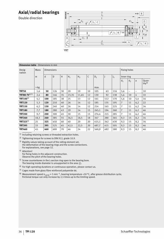
Axial/radial bearingsDouble direction
YRT
0001
8406
0001
8406
1) Including retaining screws or threaded extraction holes.2) Tightening torque for screws to DIN 912, grade 10.9.3) Rigidity values taking account of the rolling element set,
the deformation of the bearing rings and the screw connections.For explanations, see page 32.
4) Attention!For fixing holes in the adjacent construction.Observe the pitch of the bearing holes.
5) Screw counterbores in the L-section ring open to the bearing bore.The bearing inside diameter is unsupported in the area �.
6) For high operating durations or continuous operation, please contact us.7) Cages made from glass fibre reinforced polyamide 66.8) Measurement speed nconst = 5 min–1, bearing temperature +50 °C, after grease distribution cycle;
frictional torque can only increase by 2,5 times up to the limiting speed.
Dimension table · Dimensions in mm
Desig-nation
Mass Dimensions Fixing holes
m d D H H1 H2 C D1 J J1 Inner ring
d1 d2 a Quan-tity4)
�kg max.
YRT50 1,6 50 126 30 20 10 10 105 63 116 5,6 – – 10
YRT80-TV5)7) 2,4 80 146 35 23,35 11,65 12 130 92 138 5,6 10 4 10
YRT1005) 4,1 100 185 38 25 13 12 161 112 170 5,6 10 5,4 16
YRT120 5,3 120 210 40 26 14 12 185 135 195 7 11 6,2 22
YRT150 6,2 150 240 40 26 14 12 214 165 225 7 11 6,2 34
YRT180 7,7 180 280 43 29 14 15 245,1 194 260 7 11 6,2 46
YRT200 9,7 200 300 45 30 15 15 274,4 215 285 7 11 6,2 46
YRT260 18,3 260 385 55 36,5 18,5 18 347 280 365 9,3 15 8,2 34
YRT3255) 25 325 450 60 40 20 20 415,1 342 430 9,3 15 8,2 34
YRT395 33 395 525 65 42,5 22,5 20 487,7 415 505 9,3 15 8,2 46
YRT460 45 460 600 70 46 24 22 560,9 482 580 9,3 15 8,2 46
ST4_9007205161149195_yrt.fm Seite 36 Freitag, 19. August 2016 7:34 07
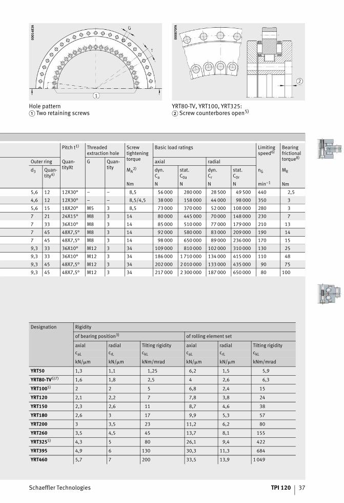
Schaeffler Technologies TPI 120 37
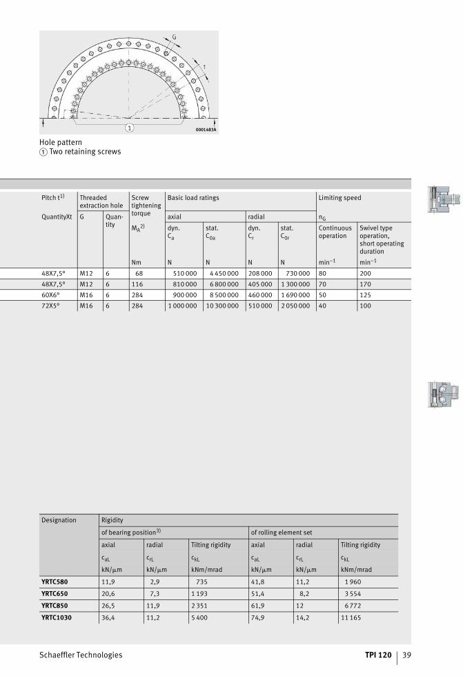
Hole pattern� Two retaining screws
0001
483A
0001
483A
YRT80-TV, YRT100, YRT325:� Screw counterbores open5)
0008
70FA
0008
70FA
Pitch t1) Threaded extraction hole
Screw tightening torque
Basic load ratings Limitingspeed6)
Bearing frictional torque8)
Outer ring Quan-tityXt
G Quan-tity
axial radial
d3 Quan-tity4)
MA2) dyn.
Ca
stat.C0a
dyn.Cr
stat.C0r
nG MR
Nm N N N N min–1 Nm
5,6 12 12X30° – – 8,5 56 000 280 000 28 500 49 500 440 2,5
4,6 12 12X30° – – 8,5/4,5 38 000 158 000 44 000 98 000 350 3
5,6 15 18X20° M5 3 8,5 73 000 370 000 52 000 108 000 280 3
7 21 24X15° M8 3 14 80 000 445 000 70 000 148 000 230 7
7 33 36X10° M8 3 14 85 000 510 000 77 000 179 000 210 13
7 45 48X7,5° M8 3 14 92 000 580 000 83 000 209 000 190 14
7 45 48X7,5° M8 3 14 98 000 650 000 89 000 236 000 170 15
9,3 33 36X10° M12 3 34 109 000 810 000 102 000 310 000 130 25
9,3 33 36X10° M12 3 34 186 000 1 710 000 134 000 415 000 110 48
9,3 45 48X7,5° M12 3 34 202 000 2 010 000 133 000 435 000 90 75
9,3 45 48X7,5° M12 3 34 217 000 2 300 000 187 000 650 000 80 100
Designation Rigidity
of bearing position3) of rolling element set
axial radial Tilting rigidity axial radial Tilting rigiditycaL crL ckL caL crL ckL
kN/�m kN/�m kNm/mrad kN/�m kN/�m kNm/mrad
YRT50 1,3 1,1 1,25 6,2 1,5 5,9
YRT80-TV5)7) 1,6 1,8 2,5 4 2,6 6,3
YRT1005) 2 2 5 6,8 2,4 15
YRT120 2,1 2,2 7 7,8 3,8 24
YRT150 2,3 2,6 11 8,7 4,6 38
YRT180 2,6 3 17 9,9 5,3 57
YRT200 3 3,5 23 11,2 6,2 80
YRT260 3,5 4,5 45 13,7 8,1 155
YRT3255) 4,3 5 80 26,1 9,4 422
YRT395 4,9 6 130 30,3 11,3 684
YRT460 5,7 7 200 33,5 13,9 1 049
38 TPI 120 Schaeffler Technologies
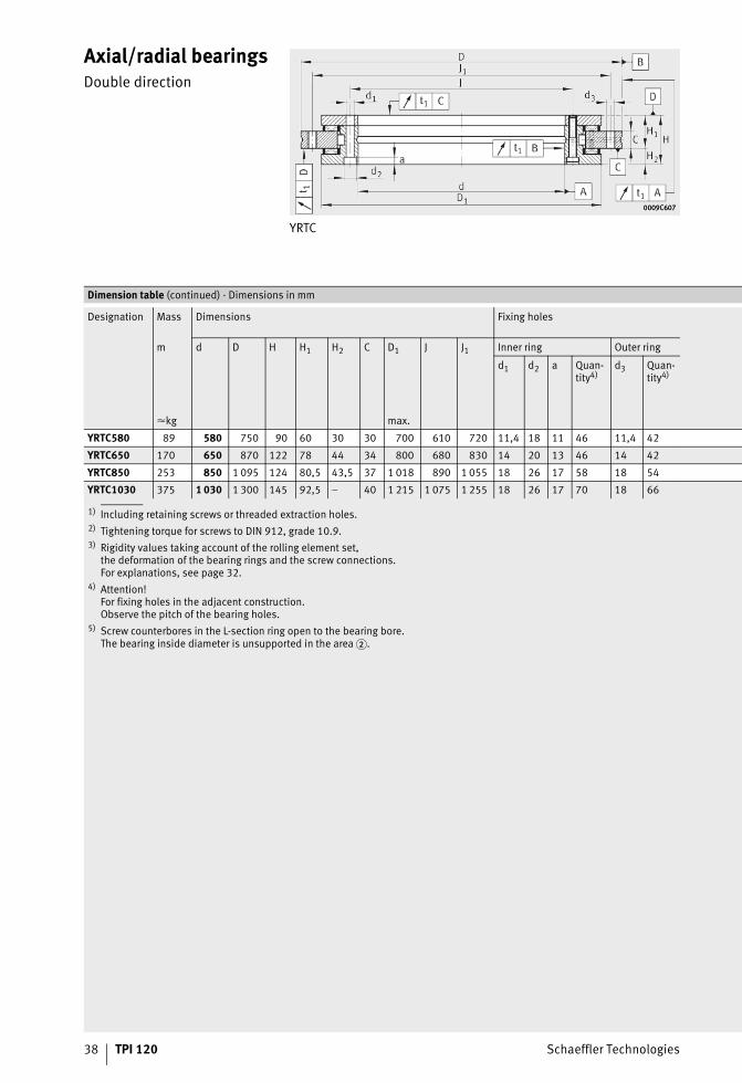
Axial/radial bearingsDouble direction
YRTC
0009C6070009C607
1) Including retaining screws or threaded extraction holes.2) Tightening torque for screws to DIN 912, grade 10.9.3) Rigidity values taking account of the rolling element set,
the deformation of the bearing rings and the screw connections.For explanations, see page 32.
4) Attention!For fixing holes in the adjacent construction.Observe the pitch of the bearing holes.
5) Screw counterbores in the L-section ring open to the bearing bore.The bearing inside diameter is unsupported in the area �.
Dimension table (continued) · Dimensions in mm
Designation Mass Dimensions Fixing holes
m d D H H1 H2 C D1 J J1 Inner ring Outer ring
d1 d2 a Quan-tity4)
d3 Quan-tity4)
�kg max.
YRTC580 89 580 750 90 60 30 30 700 610 720 11,4 18 11 46 11,4 42
YRTC650 170 650 870 122 78 44 34 800 680 830 14 20 13 46 14 42
YRTC850 253 850 1 095 124 80,5 43,5 37 1 018 890 1 055 18 26 17 58 18 54
YRTC1030 375 1 030 1 300 145 92,5 – 40 1 215 1 075 1 255 18 26 17 70 18 66
ST4_9007205161149195_yrt.fm Seite 38 Freitag, 19. August 2016 7:35 07
Schaeffler Technologies TPI 120 39
Hole pattern� Two retaining screws
0001483A0001483A
Pitch t1) Threaded extraction hole
Screw tightening torque
Basic load ratings Limiting speed
QuantityXt G Quan-tity
axial radial nG
MA2) dyn.
Ca
stat.C0a
dyn.Cr
stat.C0r
Continuous operation
Swivel typeoperation,short operatingduration
Nm N N N N min–1 min–1
48X7,5° M12 6 68 510 000 4 450 000 208 000 730 000 80 200
48X7,5° M12 6 116 810 000 6 800 000 405 000 1 300 000 70 170
60X6° M16 6 284 900 000 8 500 000 460 000 1 690 000 50 125
72X5° M16 6 284 1 000 000 10 300 000 510 000 2 050 000 40 100
Designation Rigidity
of bearing position3) of rolling element set
axial radial Tilting rigidity axial radial Tilting rigidity
caL crL ckL caL crL ckL
kN/�m kN/�m kNm/mrad kN/�m kN/�m kNm/mrad
YRTC580 11,9 2,9 735 41,8 11,2 1 960
YRTC650 20,6 7,3 1 193 51,4 8,2 3 554
YRTC850 26,5 11,9 2 351 61,9 12 6 772
YRTC1030 36,4 11,2 5 400 74,9 14,2 11 165
ST4_9007205161149195_yrt.fm Seite 39 Freitag, 19. August 2016 7:35 07
40 TPI 120 Schaeffler Technologies
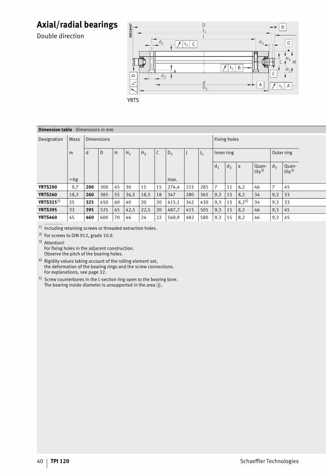
Axial/radial bearingsDouble direction
YRTS
0001
8407
0001
8407
1) Including retaining screws or threaded extraction holes.2) For screws to DIN 912, grade 10.9.3) Attention!
For fixing holes in the adjacent construction.Observe the pitch of the bearing holes.
4) Rigidity values taking account of the rolling element set,the deformation of the bearing rings and the screw connections.For explanations, see page 32.
5) Screw counterbores in the L-section ring open to the bearing bore.The bearing inside diameter is unsupported in the area �.
Dimension table · Dimensions in mm
Designation Mass Dimensions Fixing holes
m d D H H1 H2 C D1 J J1 Inner ring Outer ring
d1 d2 a Quan-tity3)
d3 Quan-tity3)
�kg max.
YRTS200 9,7 200 300 45 30 15 15 274,4 215 285 7 11 6,2 46 7 45
YRTS260 18,3 260 385 55 36,5 18,5 18 347 280 365 9,3 15 8,2 34 9,3 33
YRTS3255) 25 325 450 60 40 20 20 415,1 342 430 9,3 15 8,25) 34 9,3 33
YRTS395 33 395 525 65 42,5 22,5 20 487,7 415 505 9,3 15 8,2 46 9,3 45
YRTS460 45 460 600 70 46 24 22 560,9 482 580 9,3 15 8,2 46 9,3 45
ST4_9007205162910475_yrts.fm Seite 40 Freitag, 19. August 2016 7:35 07
Schaeffler Technologies TPI 120 41
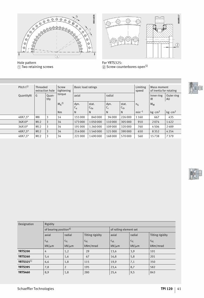
Hole pattern� Two retaining screws
0001
483A
0001
483A
For YRTS325:� Screw counterbores open5)
0009
B117
0009
B117
Pitch t1) Threaded extraction hole
Screw tightening torque
Basic load ratings Limitingspeed
Mass momentof inertia for rotating
QuantityXt G Quan-tity
axial radial Inner ringIR
Outer ringAU
MA2) dyn.
Ca
stat.C0a
dyn.Cr
stat.C0r
nG MM
Nm N N N N min–1 kg�cm2 kg�cm2
48X7,5° M8 3 14 155 000 840 000 94 000 226 000 1 160 667 435
36X10° M12 3 34 173 000 1 050 000 110 000 305 000 910 2 074 1 422
36X10° M12 3 34 191 000 1 260 000 109 000 320 000 760 4 506 2 489
48X7,5° M12 3 34 214 000 1 540 000 121 000 390 000 650 8 352 4 254
48X7,5° M12 3 34 221 000 1 690 000 168 000 570 000 560 15 738 7 379
Designation Rigidity
of bearing position4) of rolling element set
axial radial Tilting rigidity axial radial Tilting rigidity
caL crL ckL caL crL ckL
kN/�m kN/�m kNm/mrad kN/�m kN/�m kNm/mrad
YRTS200 4 1,2 29 13,6 3,9 101
YRTS260 5,4 1,6 67 16,8 5,8 201
YRTS3255) 6,6 1,8 115 19,9 7,1 350
YRTS395 7,8 2 195 23,4 8,7 582
YRTS460 8,9 1,8 280 25,4 9,5 843
ST4_9007205162910475_yrts.fm Seite 41 Freitag, 19. August 2016 7:35 07
42 TPI 120 Schaeffler Technologies
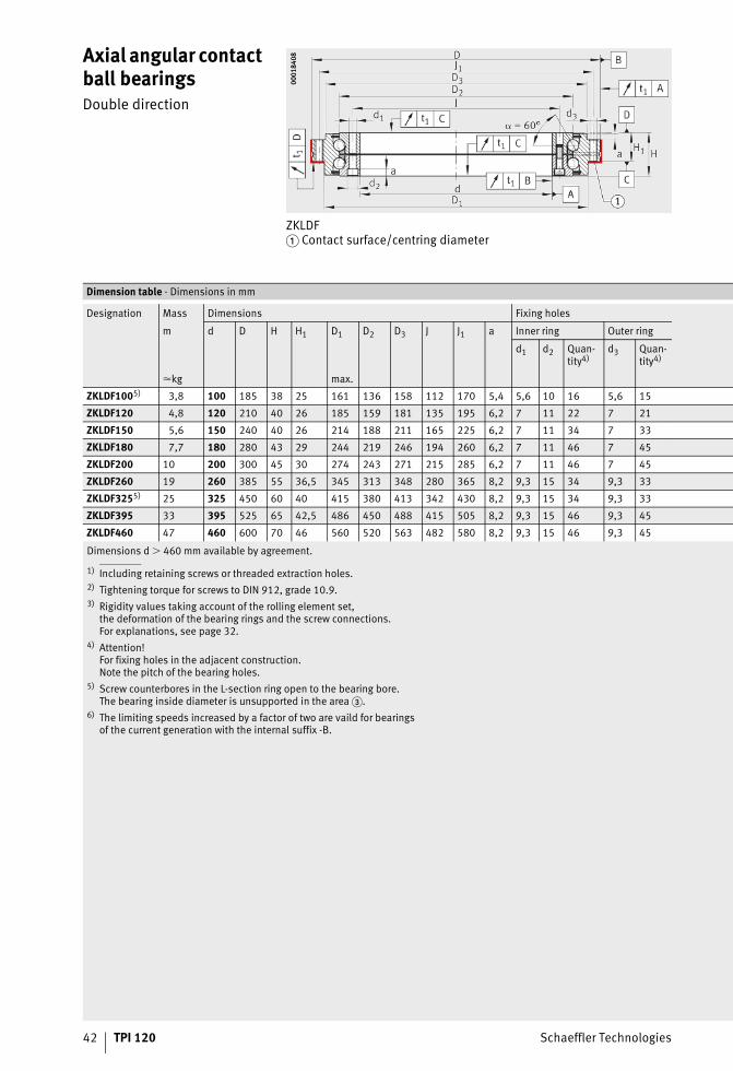
Axial angular contact ball bearingsDouble direction
ZKLDF� Contact surface/centring diameter
0001
8408
0001
8408
Dimensions d � 460 mm available by agreement.
1) Including retaining screws or threaded extraction holes.2) Tightening torque for screws to DIN 912, grade 10.9.3) Rigidity values taking account of the rolling element set,
the deformation of the bearing rings and the screw connections.For explanations, see page 32.
4) Attention!For fixing holes in the adjacent construction.Note the pitch of the bearing holes.
5) Screw counterbores in the L-section ring open to the bearing bore.The bearing inside diameter is unsupported in the area �.
6) The limiting speeds increased by a factor of two are vaild for bearingsof the current generation with the internal suffix -B.
Dimension table · Dimensions in mm
Designation Mass Dimensions Fixing holes
m d D H H1 D1 D2 D3 J J1 a Inner ring Outer ring
d1 d2 Quan-tity4)
d3 Quan-tity4)
�kg max.
ZKLDF1005) 3,8 100 185 38 25 161 136 158 112 170 5,4 5,6 10 16 5,6 15
ZKLDF120 4,8 120 210 40 26 185 159 181 135 195 6,2 7 11 22 7 21
ZKLDF150 5,6 150 240 40 26 214 188 211 165 225 6,2 7 11 34 7 33
ZKLDF180 7,7 180 280 43 29 244 219 246 194 260 6,2 7 11 46 7 45
ZKLDF200 10 200 300 45 30 274 243 271 215 285 6,2 7 11 46 7 45
ZKLDF260 19 260 385 55 36,5 345 313 348 280 365 8,2 9,3 15 34 9,3 33
ZKLDF3255) 25 325 450 60 40 415 380 413 342 430 8,2 9,3 15 34 9,3 33
ZKLDF395 33 395 525 65 42,5 486 450 488 415 505 8,2 9,3 15 46 9,3 45
ZKLDF460 47 460 600 70 46 560 520 563 482 580 8,2 9,3 15 46 9,3 45
ST4_9007205163501067_zkldf.fm Seite 42 Freitag, 19. August 2016 7:35 07
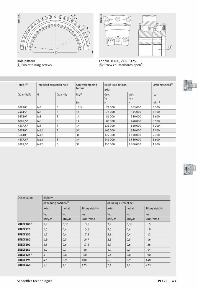
Schaeffler Technologies TPI 120 43
Hole pattern� Two retaining screws
0001
483C
0001
483C
For ZKLDF100, ZKLDF325:� Screw counterbores open5)
0009
B120
0009
B120
Pitch t1) Threaded extraction hole Screw tightening torque
Basic load ratings Limiting speed6)
axial
QuantityXt G Quantity MA2) dyn.
Ca
stat.C0a
nG
Nm N N min–1
18X20° M5 3 8,5 71 000 265 000 5 000
24X15° M8 3 14 76 000 315 000 4 300
36X10° M8 3 14 81 000 380 000 3 600
48X7,5° M8 3 14 85 000 440 000 3 500
48X7,5° M8 3 14 121 000 610 000 3 200
36X10° M12 3 34 162 000 920 000 2 400
36X10° M12 3 34 172 000 1 110 000 2 000
48X7,5° M12 3 34 241 000 1 580 000 1 600
48X7,5° M12 3 34 255 000 1 860 000 1 400
Designation Rigidity
of bearing position3) of rolling element set
axial radial Tilting rigidity axial radial Tilting rigidity
caL crL ckL caL crL ckL
kN/�m kN/�m kNm/mrad kN/�m kN/�m kNm/mrad
ZKLDF1005) 1,2 0,35 3,6 2,2 0,35 5
ZKLDF120 1,5 0,4 5,5 2,5 0,4 8
ZKLDF150 1,7 0,4 7,8 2,9 0,4 12
ZKLDF180 1,9 0,5 10,7 2,8 0,5 16
ZKLDF200 2,5 0,6 17,5 3,7 0,6 26
ZKLDF260 3,2 0,7 40 4,7 0,7 54
ZKLDF3255) 4 0,8 60 5,4 0,8 90
ZKLDF395 4,5 0,9 100 6,3 0,9 148
ZKLDF460 5,3 1,1 175 7,1 1,1 223
ST4_9007205163501067_zkldf.fm Seite 43 Freitag, 19. August 2016 7:35 07
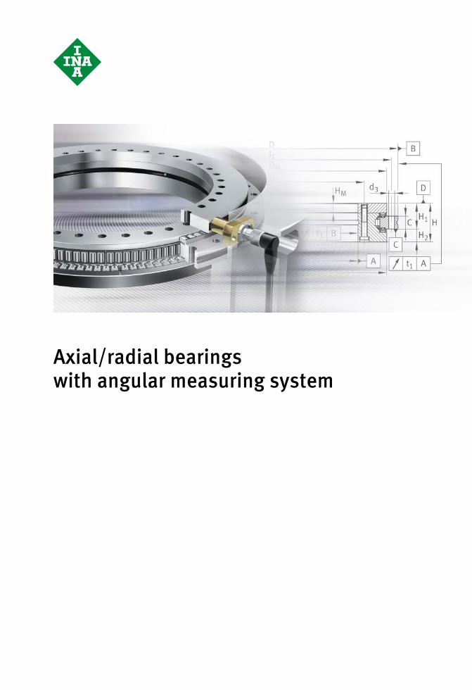
Axial/radial bearingswith angular measuring system
ST4_9007205176706059_vorspann.fm Seite 44 Freitag, 19. August 2016 7:35 07
Schaeffler Technologies TPI 120 45
Page
Axial/radial bearingswith angular measuring system
Product overview Axial/radial bearings with angular measuring system................. 46
Features Advantages of the angular measuring system............................. 47
Dimensional scale ..................................................................... 48
Measuring heads with magneto-resistive sensors....................... 49
Electronic evaluation system ..................................................... 49
Cables for signal transmission ................................................... 50
Setting and diagnosis program .................................................. 52
Measurement accuracy.............................................................. 53
Error-free signal transmission .................................................... 55
Measures to protect against interference ................................... 56
Laying of signal cables............................................................... 58
Compatibility............................................................................. 59
Test according to standard......................................................... 60
Technical data........................................................................... 62
Detection of zero position, functional principle .......................... 64
Special design........................................................................... 64
Design andsafety guidelines
Design of adjacent construction................................................. 65
Safety-related information about the measuring deviceunder the terms of the Machinery Directive ................................ 67
Fitting........................................................................................ 68
Ordering example,ordering designation
Unit........................................................................................... 70
Also required............................................................................. 71
Replacement parts..................................................................... 71
Dimension tables Axial/radial bearings, double direction,with measuring system .............................................................. 72
SRM electronic measuring system.............................................. 76
ST4_1729221643_ivz.fm Seite 45 Freitag, 19. August 2016 7:35 07
46 TPI 120 Schaeffler Technologies
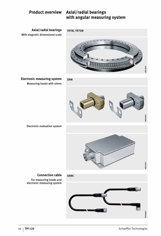
Product overview Axial/radial bearingswith angular measuring system
Axial/radial bearingsWith magnetic dimensional scale
YRTM, YRTSM
0001
A63F
0001
A63F
Electronic measuring systemMeasuring heads with shims
SRM
0001
A640
0001
A640
Electronic evaluation system
0001
A641
0001
A641
Connection cableFor measuring heads and
electronic measuring system
SRMC
0001
A642
0001
A642
ST4_5922070155_produktuebersic.fm Seite 46 Freitag, 19. August 2016 7:36 07
Schaeffler Technologies TPI 120 47
Axial/radial bearingswith angular measuring system
Features Axial/radial bearings with angular measuring system comprise:■ an axial/radial bearing YRTM or YRTSM with a dimensional scale,
an SRM electronic measuring system and signal leads SRMC.The electronic measuring system SRM comprises two measuring heads, two stacks of shims and an electronic evaluation system. The signal leads for connecting the measuring heads to theelectronic evaluation system can be ordered individually invarious designs. The electronic measuring system MEKO/Uwill continue to be available but should no longer be usedfor new designs.
Bearings of series YRTM or YRTSM correspond in mechanical termsto axial/radial bearings YRT or YRTS but are additionally fitted witha magnetic dimensional scale. The measuring system can measure angles to an accuracy of a few angular seconds by non-contact, magneto-resistive means.For the mechanical part of axial/radial bearings YRTM or YRTSM, please refer to the information from page 7 to page 34.
Advantagesof the angular measuring
system
The measuring system, Figure 1, page 48:■ allows, due to the rigid connection to the adjacent construction,
very good control characteristics (control stability and dynamics) and is therefore particularly suitable for axes with torque motor drive
■ offers a high maximum speed of up to 16,5 m/s■ operates by non-contact means and is therefore not subject
to wear■ carries out measurement irrespective of tilting and position■ has automatically self-adjusting electronics■ has a self-centring function■ is unaffected by lubricants■ is easy to fit, the measuring heads are easily adjustable,
there is no need for alignment of the bearing and a separate measuring system
■ requires no additional parts– the dimensional scale and measuring heads are integrated
in the bearing and adjacent construction respectively– the resulting space saved can be used for the machining area
of the machine■ does not give any problems relating to supply cables.
The cables can be laid within the adjacent construction directly through the large bearing bore
■ gives savings on design envelope size and costs due tothe compact, integrated design requiring fewer components.
ST4_9007200957576203_beschreib.fm Seite 47 Freitag, 19. August 2016 7:36 07
48 TPI 120 Schaeffler Technologies
Axial/radial bearings with angular measuring system
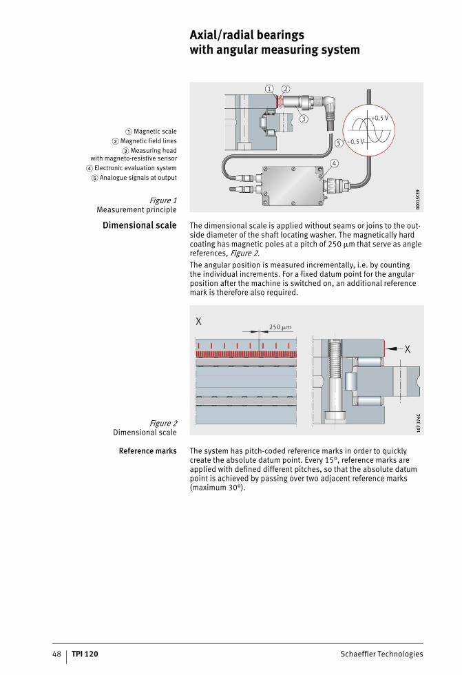
Dimensional scale The dimensional scale is applied without seams or joins to the out-side diameter of the shaft locating washer. The magnetically hard coating has magnetic poles at a pitch of 250 �m that serve as angle references, Figure 2.The angular position is measured incrementally, i.e. by countingthe individual increments. For a fixed datum point for the angular position after the machine is switched on, an additional reference mark is therefore also required.
Reference marks The system has pitch-coded reference marks in order to quickly create the absolute datum point. Every 15°, reference marks are applied with defined different pitches, so that the absolute datum point is achieved by passing over two adjacent reference marks (maximum 30°).
� Magnetic scale� Magnetic field lines
� Measuring headwith magneto-resistive sensor
� Electronic evaluation system� Analogue signals at output
Figure 1Measurement principle 00
015C
E900
015C
E9
Figure 2Dimensional scale 10
7 37
4C10
7 37
4C
ST4_9007200957576203_beschreib.fm Seite 48 Freitag, 19. August 2016 7:36 07
Schaeffler Technologies TPI 120 49
Measuring heads withmagneto-resistive sensors
The measuring heads are colour coded:■ the silver measuring head (white) scans the incremental track■ the gold measuring head (yellow) scans the incremental track
and the reference marks.The two measuring heads are designed for optimum use of space. They are fixed in a slot in the adjacent construction by means oftwo fixing screws.
MR effect The small magnetic fields are detected as a result ofthe magneto-resistive effect (MR effect). Compared with magnetic heads, the MR sensors allow static measurement of magnetic fields, i.e. electrical signals are derived without movement, in contrastto magnetic heads.The resistance layer of the MR sensors is designed such thatthe resistance changes when a magnetic field is perpendicularto the current flow.When the magnetic pitch moves past the MR sensor, two sine wave signals with a phase offset of 90° are generated with a period length of 500 �m.
O-rings for sealing The measuring heads have O-rings to seal against the egress of oil and the ingress of fluids such as cooling lubricants.
Electronic evaluation system The electronic evaluation system operates with the aid of a digital signal processor (DSP).The input signals are digitised by an analogue/digital converter.The high performance processor (DSP) automatically comparesthe sensor signals and calculates the effective angular value from the sensor signals by means of vector addition. Correction is carried out, for example, on the offset of the analogue signals.A digital/analogue converter generates synthetic analogue signals as a 1 VSS value.The electronic evaluation system can be positioned at any location or within the adjacent construction. It is connected to the controller by means of a conventional 12-pin extension cable.The lead for transmitting the voltage signals from the electronic evaluation system to the electronic post-processor can beup to 100 m long.
ST4_9007200957576203_beschreib.fm Seite 49 Freitag, 19. August 2016 7:37 07
50 TPI 120 Schaeffler Technologies
Axial/radial bearings with angular measuring system
Cables for signal transmission The signal cables for connecting the measuring heads to theelectronic evaluation system are available in the lengths 1 m, 2 m and 3 m, see table, page 51.The connection side for the electronic evaluation system has a straight plug. The connection side to the measuring head is suitable for straight plugs or 90° elbow plugs.In the case of the elbow plug, the cable outlet direction is definedin relation to the mounting position of the measuring heads.
Advantages The cables are suitable for use in machinery and plant for chip-forming machining:■ the cables and plugs are shielded■ the cable sheathing is made from polyurethane (PUR),
halogen-free and flame-resistant■ the signal cables are free from halogens, silicones and PVC
as well as resistant to microbes and hydrolysis■ the cables are resistant to oils, greases and cooling lubricants■ the cables are suitable for dynamic use in flexible trunking
(it must be ensured that they are laid correctly).
Bending cycles When laid in flexible trunking, the cables can achieve � 2 million bending cycles under the following test conditions:■ bending radius 65 mm (10�D)■ acceleration 5 m/s2
■ travel speed 200 m/min■ travel distance 5 m, horizontally.
Plug connectors INA plug connectors are robust and designed for use in industrial environments. When connected, they conform to protection grade IP 65 (DIN EN 60529).The large sheathed areas of the plugs ensure effective shielding.
ST4_9007200957576203_beschreib.fm Seite 50 Freitag, 19. August 2016 7:37 07
Schaeffler Technologies TPI 120 51
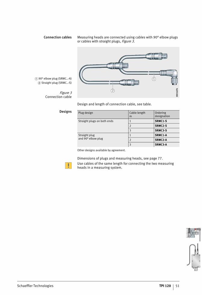
Connection cables Measuring heads are connected using cables with 90° elbow plugs or cables with straight plugs, Figure 3.
Design and length of connection cable, see table.
Designs
Other designs available by agreement.
Dimensions of plugs and measuring heads, see page 77.Use cables of the same length for connecting the two measuring heads in a measuring system.
� 90° elbow plug (SRMC..-A)� Straight plug (SRMC..-S)
Figure 3Connection cable 00
0162
F400
0162
F4
Plug design Cable length Ordering designationm
Straight plugs on both ends 1 SRMC1-S2 SRMC2-S3 SRMC3-S
Straight plugand 90° elbow plug
1 SRMC1-A2 SRMC2-A3 SRMC3-A
ST4_9007200957576203_beschreib.fm Seite 51 Freitag, 19. August 2016 7:37 07
52 TPI 120 Schaeffler Technologies
Axial/radial bearings with angular measuring system
Setting anddiagnosis program
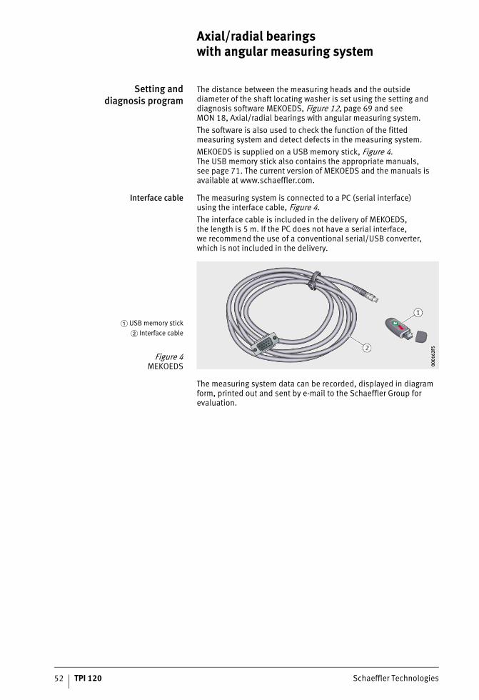
The distance between the measuring heads and the outside diameter of the shaft locating washer is set using the setting and diagnosis software MEKOEDS, Figure 12, page 69 and seeMON 18, Axial/radial bearings with angular measuring system.The software is also used to check the function of the fitted measuring system and detect defects in the measuring system.MEKOEDS is supplied on a USB memory stick, Figure 4.The USB memory stick also contains the appropriate manuals,see page 71. The current version of MEKOEDS and the manuals isavailable at www.schaeffler.com.
Interface cable The measuring system is connected to a PC (serial interface)using the interface cable, Figure 4.The interface cable is included in the delivery of MEKOEDS, the length is 5 m. If the PC does not have a serial interface,we recommend the use of a conventional serial/USB converter, which is not included in the delivery.
The measuring system data can be recorded, displayed in diagram form, printed out and sent by e-mail to the Schaeffler Group for evaluation.
� USB memory stick� Interface cable
Figure 4MEKOEDS 00
0162
F500
0162
F5
ST4_9007200957576203_beschreib.fm Seite 52 Freitag, 19. August 2016 7:37 07
Schaeffler Technologies TPI 120 53
Measurement accuracy The more accurate the angular measurement, the more accuratelya rotary axis can be positioned. The accuracy of angular measure-ment is essentially determined by:
For the measuring system integrated in the bearing,only points � to � are relevant.The eccentricity in point � is completely eliminated bythe diametrically opposed arrangement of the MR sensors.Points � to � play only a very minor role in the INA measuring system.
Positional deviations Positional deviations within a revolution are the absolute measurement errors over one revolution of the system(measured at +20 °C ambient temperature):■ YRTM150 � �6�
■ YRTM180 � �5�
■ YRT(S)M200, YRT(S)M260, YRT(S)M325, YRT(S)M395, YRT(S)M460 � �3�.
Since the dimensional scale is directly connected, i.e. withoutany compensation elements, with the rolling bearing, deflectionsin the bearing raceway system due to machining forces could affect the measurement result. This effect is eliminated by the diametri-cally opposed arrangement of the measuring heads in the electronic evaluation system.
� the quality of the dimensional scale� the quality of scanning� the quality of the electronic evaluation system� the eccentricity of the dimensional scale to the
bearing raceway system� the runout deviation of the bearing arrangement� the elasticity of the measurement system shaft and
its linkage to the shaft to be measured� the elasticity of the stator shaft and shaft coupling.
ST4_9007200957576203_beschreib.fm Seite 53 Freitag, 19. August 2016 7:37 07
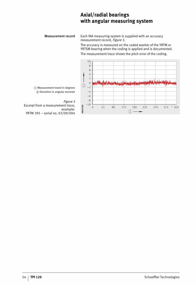
54 TPI 120 Schaeffler Technologies
Axial/radial bearings with angular measuring system
Measurement record Each INA measuring system is supplied with an accuracy measurement record, Figure 5.The accuracy is measured on the coded washer of the YRTM orYRTSM bearing when the coding is applied and is documented.The measurement trace shows the pitch error of the coding.
� Measurement travel in degrees� Deviation in angular seconds
Figure 5Excerpt from a measurement trace,
example:YRTM 395 – serial no. 03/09/004 00
015C
EA00
015C
EA
ST4_9007200957576203_beschreib.fm Seite 54 Freitag, 19. August 2016 7:37 07
Schaeffler Technologies TPI 120 55
Error-free signal transmission If the INA measuring system is fitted and operated as specified,it fulfils the requirements of Directives 89/336/EEC and92/031/EEC for electromagnetic compatibility (EMC).Adherence to the EMC directive in accordance with the following standards is demonstrated:■ EN 61000-6-2 Immunity
– ESD:EN 61000-4-2
– radiated electromagnetic fields:EN 61000-4-3
– burst:EN 61000-4-4
– surge:EN 61000-4-5
– conducted immunity:EN 61000-4-6
– magnetic field:EN 61000-4-8
■ EN 55 011-B Emission– interference voltage:
EN 55 011-B– perturbing radiation:
EN 55 011-B.
Possible sources of electricalinterference in the transmission
of measurement signals
Disruptive voltage is mainly generated and transmitted by capacitive or inductive interference. Interference can occur through lines and equipment inputs and outputs.Sources of interference include:■ strong magnetic fields due to transformers and electric motors■ relays, contactors and solenoid valves■ high frequency equipment, pulse devices and magnetic stray
fields due to switched-mode power supply units■ supply mains and leads to the equipment mentioned above.Interference in initial operation can generally be attributed to absent or inadequate shielding of the measurement leads or insufficient spacing between the signal and power cables.The overall design should be such that the function of the measuring system is not influenced by sources of electrical or mechanical interference.
ST4_9007200957576203_beschreib.fm Seite 55 Freitag, 19. August 2016 7:37 07
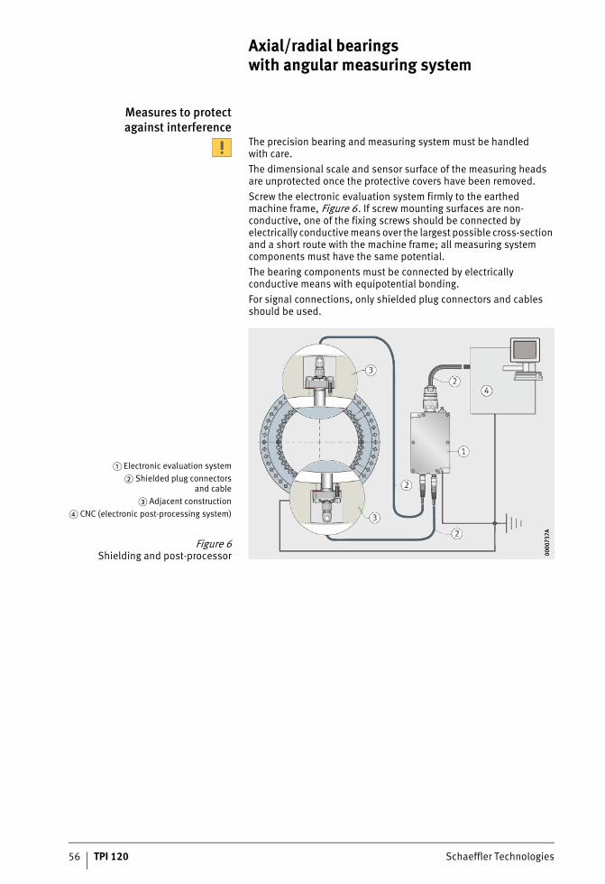
56 TPI 120 Schaeffler Technologies
Axial/radial bearings with angular measuring system
Measures to protectagainst interference
The precision bearing and measuring system must be handledwith care.The dimensional scale and sensor surface of the measuring heads are unprotected once the protective covers have been removed.Screw the electronic evaluation system firmly to the earthed machine frame, Figure 6. If screw mounting surfaces are non-conductive, one of the fixing screws should be connected by electrically conductive means over the largest possible cross-section and a short route with the machine frame; all measuring system components must have the same potential.The bearing components must be connected by electrically conductive means with equipotential bonding.For signal connections, only shielded plug connectors and cables should be used.
� Electronic evaluation system� Shielded plug connectors
and cable� Adjacent construction
� CNC (electronic post-processing system)
Figure 6Shielding and post-processor 00
0073
7A00
0073
7A
ST4_9007200957576203_beschreib.fm Seite 56 Freitag, 19. August 2016 7:37 07
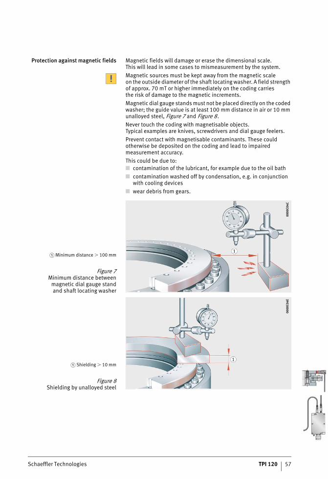
Schaeffler Technologies TPI 120 57
Protection against magnetic fields Magnetic fields will damage or erase the dimensional scale.This will lead in some cases to mismeasurement by the system.Magnetic sources must be kept away from the magnetic scaleon the outside diameter of the shaft locating washer. A field strength of approx. 70 mT or higher immediately on the coding carriesthe risk of damage to the magnetic increments.Magnetic dial gauge stands must not be placed directly on the coded washer; the guide value is at least 100 mm distance in air or 10 mm unalloyed steel, Figure 7 and Figure 8.Never touch the coding with magnetisable objects.Typical examples are knives, screwdrivers and dial gauge feelers.Prevent contact with magnetisable contaminants. These could otherwise be deposited on the coding and lead to impaired measurement accuracy.This could be due to:■ contamination of the lubricant, for example due to the oil bath■ contamination washed off by condensation, e.g. in conjunction
with cooling devices■ wear debris from gears.
� Minimum distance � 100 mm
Figure 7Minimum distance between
magnetic dial gauge standand shaft locating washer
0000
C04C
0000
C04C
� Shielding � 10 mm
Figure 8Shielding by unalloyed steel
0000
C04E
0000
C04E
ST4_9007200957576203_beschreib.fm Seite 57 Freitag, 19. August 2016 7:37 07
58 TPI 120 Schaeffler Technologies
Axial/radial bearings with angular measuring system
Pressing downthe measuring head by hand
In order to protect the sensor chip against damage, the measuring head can only be pressed against the dimensional scale by hand. Forces � 50 N can lead to sensor damage.
Laying of signal cables Laying of disruptive and suppressed or non-disruptive cablesin parallel and in spatial vicinity should be avoided. Separationin air of � 100 mm is recommended. If adequate spacing cannotbe achieved, additional shielding or earthed metallic partitionwalls between the cables should be provided.The requirement for spatial separation of cables also appliesto typical sources of interference such as servo drives, frequency converters, contactors, solenoid valves and choking coils.
Crossings If cables must be crossed, this should be carried out at a 90° angleif possible.
Overlong cables Overlong cables that are located rolled up in the switch cabinetwill act as antennae and cause unnecessary interference.These cables should be cut to the required length.
Shielding If shield separations are necessary, these should be reconnected over as large an area as possible. The free lead ends to the connector terminal should be as short as possible.Shield separations are a functional risk and should thereforebe avoided.
Ends not required Non-assigned ends should be connected on both sideswith reference potential (chassis ground).
Motor connectors No other cables for data cabling should be fed within shielded motor cables or terminal boxes for motor connectors. Spatial separation is also recommended here, for example by sheet metal partitions.
Interference suppression filter Connections between interference suppression filters andthe emission source should be kept as short as possible andshould be shielded.
ST4_9007200957576203_beschreib.fm Seite 58 Freitag, 19. August 2016 7:37 07
Schaeffler Technologies TPI 120 59
Compatibility The analogue output signals 1 VSS of the incremental track can be processed by all conventional CNC controllers.For new applications, it should be checked whether the CNC control-ler can be parametrised in accordance with the technical data of the YRTM or YRTSM.For most controllers, the input parameters can be requested from us.
Input of pulse rate On many controllers, the pulse rate can be directly inputted. Pulse rate, see table, page 62. In isolated cases, however, this is carried out via a whole number multiplication and division value.In these cases, the pulse rate cannot be entered exactly for sizes YRTM200 or YRTSM200 and YRTM395 or YRTSM395 and must be corrected using other parameters.
Pitch-coded reference marks Some controllers cannot record signals from pitch-coded measuring systems. For these cases, the electronic measuring system can be supplied as a single reference mark measuring system. Please state this in the order text.The differential pitch between two adjacent reference marks istwo signal periods. In the zero transition area, the system designof the encoder leads to a large difference. The controller must be capable of processing this aspect.In swivel type axes, the measuring system zero point (markedon the bearing using a drill bit) can be placed outside the scanning range of the yellow measuring head.With continuous monitoring of the pitch-coded reference marks,the limiting speed nG for the reference travel must not be exceeded, see dimension table.
ST4_9007200957576203_beschreib.fm Seite 59 Freitag, 19. August 2016 7:37 07
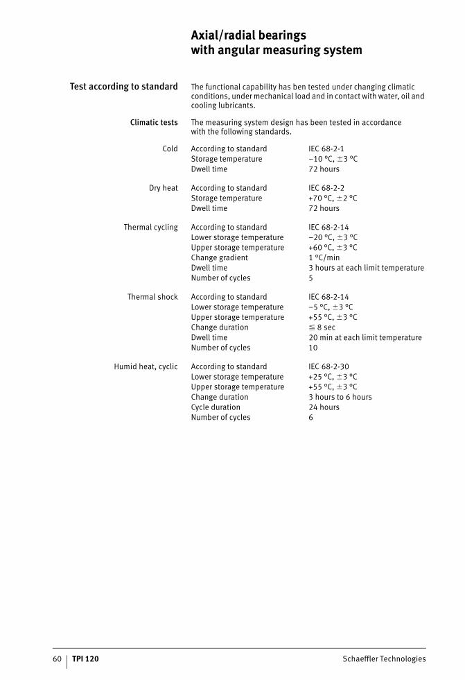
60 TPI 120 Schaeffler Technologies
Axial/radial bearings with angular measuring system
Test according to standard The functional capability has ben tested under changing climatic conditions, under mechanical load and in contact with water, oil and cooling lubricants.
Climatic tests The measuring system design has been tested in accordancewith the following standards.
Cold
Dry heat
Thermal cycling
Thermal shock
Humid heat, cyclic
According to standard IEC 68-2-1Storage temperature –10 °C, �3 °CDwell time 72 hours
According to standard IEC 68-2-2Storage temperature +70 °C, �2 °CDwell time 72 hours
According to standard IEC 68-2-14Lower storage temperature –20 °C, �3 °CUpper storage temperature +60 °C, �3 °CChange gradient 1 °C/minDwell time 3 hours at each limit temperatureNumber of cycles 5
According to standard IEC 68-2-14Lower storage temperature –5 °C, �3 °CUpper storage temperature +55 °C, �3 °CChange duration � 8 secDwell time 20 min at each limit temperatureNumber of cycles 10
According to standard IEC 68-2-30Lower storage temperature +25 °C, �3 °CUpper storage temperature +55 °C, �3 °CChange duration 3 hours to 6 hoursCycle duration 24 hoursNumber of cycles 6
ST4_9007200957576203_beschreib.fm Seite 60 Freitag, 19. August 2016 7:38 07
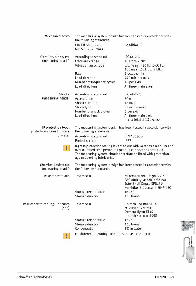
Schaeffler Technologies TPI 120 61
Mechanical tests The measuring system design has been tested in accordance with the following standards.
Vibration, sine wave(measuring heads)
Shocks(measuring heads)
IP protection type,protection against ingress
of water
The measuring system design has been tested in accordance with the following standards.
Ingress protection testing is carried out with water as a medium and over a limited time period. All push-fit connections are fitted.The measuring system should therefore be fitted with protection against cooling lubricants.
Chemical resistance(measuring heads)
The measuring system design has been tested in accordance with the following standards.
Resistance to oils
Resistance to cooling lubricants(KSS)
For different operating conditions, please contact us.
DIN EN 60086-2-6MIL-STD-202, 204 C
Condition B
According to standard IEC 68-2-6Frequency range 10 Hz to 2 kHzVibration amplitude �0,76 mm (10 Hz to 60 Hz)
100 m/s2 (60 Hz to 2 kHz)Rate 1 octave/minLoad duration 240 min per axisNumber of frequency cycles 16 per axisLoad directions All three main axes
According to standard IEC 68-2-27Acceleration 30 gShock duration 18 m/sShock type Semisine waveNumber of shock cycles 6 per axisLoad directions All three main axes
(i.e. a total of 18 cycles)
According to standard DIN 40050-9Protection type IP67
Test media Mineral oil Aral Degol BG150PAO Mobilgear SHC XMP150Ester Shell Omala EPB150PG Klüber Klübersynth GH6-150
Storage temperature +60 °CStorage duration 168 hours
Test media Unitech Hosmac SL145ZG Zubora 92F MROemeta Hycut ET46Unitech Hosmac S558
Storage temperature +35 °CStorage duration 168 hoursConcentration 5% in water
ST4_9007200957576203_beschreib.fm Seite 61 Freitag, 19. August 2016 7:38 07
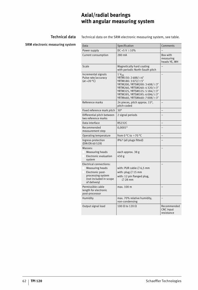
62 TPI 120 Schaeffler Technologies
Axial/radial bearings with angular measuring system
Technical data Technical data on the SRM electronic measuring system, see table.
SRM electronic measuring system Data Specification Comments
Power supply DC +5 V �10% –
Current consumption 280 mA Box with measuring heads YE, WH
Scale Magnetically hard coatingwith periodic North-South pitch
–
Incremental signalsPulse rate/accuracy(at +20 °C)
1 VSSYRTM150: 2 688/�6�YRTM180: 3 072/�5�YRTM200, YRTSM200: 3 408/�3�YRTM260, YRTSM260: 4 320/�3�YRTM325, YRTSM325: 5 184/�3�YRTM395, YRTSM395: 6 096/�3�YRTM460, YRTSM460: 7 008/�3�
–
Reference marks 24 pieces, pitch approx. 15°, pitch-coded
–
Fixed reference mark pitch 30° –
Differential pitch between two reference marks
2 signal periods –
Data interface RS232C –
Recommended measurement step
0,0001° –
Operating temperature from 0 °C to �70 °C –
Ingress protection (DIN EN 60 529)
IP67 (all plugs fitted) –
Masses:■ Measuring heads■ Electronic evaluation
system
each approx. 38 g450 g
–
Electrical connections:■ Measuring heads■ Electronic post-
processing system(not included in scope of delivery)
with: PUR cable � 6,5 mmwith: plug � 15 mmwith: 12 pin flanged plug,
� 28 mm
–
Permissible cablelength for electronic post-processor
max. 100 m –
Humidity max. 70% relative humidity,non-condensing
–
Output signal load 100 � to 120 � Recommended CNC input resistance
ST4_9007200957576203_beschreib.fm Seite 62 Freitag, 19. August 2016 7:38 07
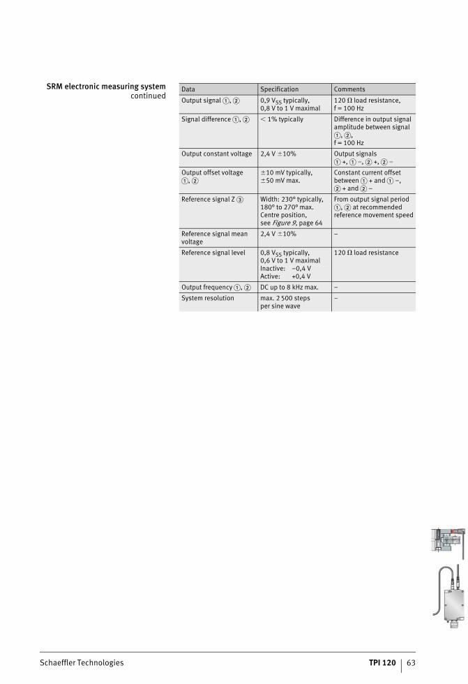
Schaeffler Technologies TPI 120 63
SRM electronic measuring systemcontinued
Data Specification Comments
Output signal �, � 0,9 VSS typically,0,8 V to 1 V maximal
120 � load resistance, f = 100 Hz
Signal difference �, � � 1% typically Difference in output signal amplitude between signal �, �,f = 100 Hz
Output constant voltage 2,4 V �10% Output signals� +, � –, � +, � –
Output offset voltage�, �
�10 mV typically,�50 mV max.
Constant current offsetbetween � + and � –,� + and � –
Reference signal Z � Width: 230° typically,180° to 270° max.Centre position,see Figure 9, page 64
From output signal period �, � at recommended reference movement speed
Reference signal mean voltage
2,4 V �10% –
Reference signal level 0,8 VSS typically,0,6 V to 1 V maximal
120 � load resistance
Inactive: Active:
–0,4 V+0,4 V
Output frequency �, � DC up to 8 kHz max. –
System resolution max. 2 500 stepsper sine wave
–
ST4_9007200957576203_beschreib.fm Seite 63 Freitag, 19. August 2016 7:38 07
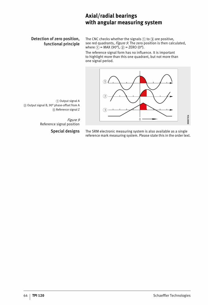
64 TPI 120 Schaeffler Technologies
Axial/radial bearings with angular measuring system
Detection of zero position,functional principle
The CNC checks whether the signals � to � are positive,see red quadrants, Figure 9. The zero position is then calculated, where � = MAX (90°), � = ZERO (0°).The reference signal form has no influence. It is importantto highlight more than this one quadrant, but not more thanone signal period.
Special designs The SRM electronic measuring system is also available as a single reference mark measuring system. Please state this in the order text.
� Output signal A� Output signal B, 90° phase-offset from A
� Reference signal Z
Figure 9Reference signal position 00
0072
C600
0072
C6
ST4_9007200957576203_beschreib.fm Seite 64 Freitag, 19. August 2016 7:38 07
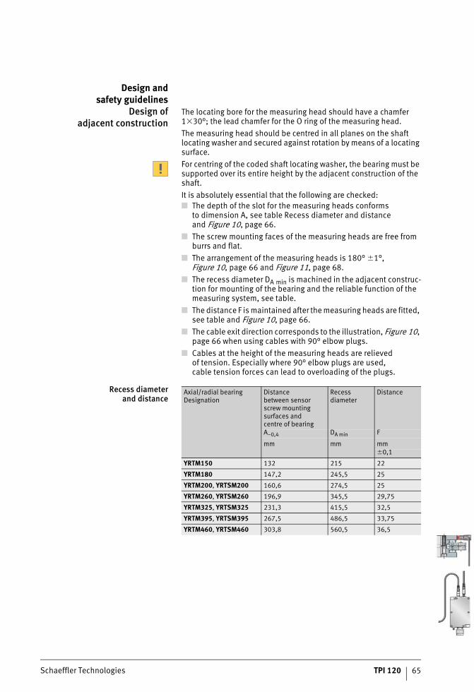
Schaeffler Technologies TPI 120 65
Design andsafety guidelines
Design ofadjacent construction
The locating bore for the measuring head should have a chamfer 1�30°; the lead chamfer for the O ring of the measuring head.The measuring head should be centred in all planes on the shaft locating washer and secured against rotation by means of a locating surface.For centring of the coded shaft locating washer, the bearing must be supported over its entire height by the adjacent construction of the shaft.It is absolutely essential that the following are checked:■ The depth of the slot for the measuring heads conforms
to dimension A, see table Recess diameter and distanceand Figure 10, page 66.
■ The screw mounting faces of the measuring heads are free from burrs and flat.
■ The arrangement of the measuring heads is 180° �1°,Figure 10, page 66 and Figure 11, page 68.
■ The recess diameter DA min is machined in the adjacent construc-tion for mounting of the bearing and the reliable function of the measuring system, see table.
■ The distance F is maintained after the measuring heads are fitted, see table and Figure 10, page 66.
■ The cable exit direction corresponds to the illustration, Figure 10, page 66 when using cables with 90° elbow plugs.
■ Cables at the height of the measuring heads are relievedof tension. Especially where 90° elbow plugs are used,cable tension forces can lead to overloading of the plugs.
Recess diameterand distance
Axial/radial bearingDesignation
Distancebetween sensorscrew mountingsurfaces andcentre of bearing
Recessdiameter
Distance
A–0,4 DA min F
mm mm mm�0,1
YRTM150 132 215 22
YRTM180 147,2 245,5 25
YRTM200, YRTSM200 160,6 274,5 25
YRTM260, YRTSM260 196,9 345,5 29,75
YRTM325, YRTSM325 231,3 415,5 32,5
YRTM395, YRTSM395 267,5 486,5 33,75
YRTM460, YRTSM460 303,8 560,5 36,5
ST4_9007200957576203_beschreib.fm Seite 65 Freitag, 19. August 2016 7:38 07
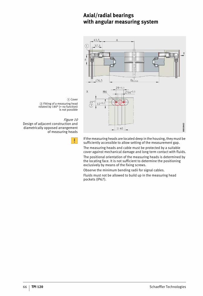
66 TPI 120 Schaeffler Technologies
Axial/radial bearings with angular measuring system
If the measuring heads are located deep in the housing, they must be sufficiently accessible to allow setting of the measurement gap.The measuring heads and cable must be protected by a suitable cover against mechanical damage and long term contact with fluids.The positional orientation of the measuring heads is determined by the locating face. It is not sufficient to determine the positioning exclusively by means of the fixing screws.Observe the minimum bending radii for signal cables.Fluids must not be allowed to build up in the measuring head pockets (IP67).
� Cover� Fitting of a measuring head
rotated by 180° (= no function)is not possible
Figure 10Design of adjacent construction anddiametrically opposed arrangement
of measuring heads 0001
8402
0001
8402
ST4_9007200957576203_beschreib.fm Seite 66 Freitag, 19. August 2016 7:38 07
Schaeffler Technologies TPI 120 67
Safety-related informationabout the measuring device
under the termsof the Machinery Directive
The angular measuring system meets the described product characteristics when used correctly. The measuring systemis not suitable for use in safety-related control circuits and shouldnot be used for this purpose. For systems with a safety focus,the positional value of the measuring device must be checked after the higher level system has been switched on. The measuringdevice is not developed in accordance with IEC 61508 and no SIL classification exists.Characteristics of the measuring device relevant to hazard analysis:■ The system does not have redundant functional elements.■ Software is involved in generating the output signals.■ If the following events occur, a zero voltage signal is outputted
by the electronic evaluation system once the initial operation procedure is complete, that can be detected by a suitable elec-tronic post-processing system as an error:– defect in the power supply– error in plausibility testing of the two measuring head signals
by means of 4 quadrant operation (detection of measuring head failure or loose connections, for example cable breakage)
– undershoot in the permissible minimum amplitudes ofthe measuring head signal (detection of measuring head failure, detection of an impermissibly large increase inthe measurement gap, for example after a machine crash).
ST4_9007200957576203_beschreib.fm Seite 67 Freitag, 19. August 2016 7:38 07
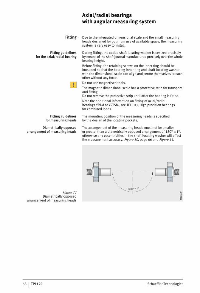
68 TPI 120 Schaeffler Technologies
Axial/radial bearings with angular measuring system
Fitting Due to the integrated dimensional scale and the small measuring heads designed for optimum use of available space, the measuring system is very easy to install.
Fitting guidelinesfor the axial/radial bearing
During fitting, the coded shaft locating washer is centred preciselyby means of the shaft journal manufactured precisely over the whole bearing height.Before fitting, the retaining screws on the inner ring should be loosened so that the bearing inner ring and shaft locating washer with the dimensional scale can align and centre themselves to each other without any force.Do not use magnetised tools.The magnetic dimensional scale has a protective strip for transport and fitting.Do not remove the protective strip until after the bearing is fitted.Note the additional information on fitting of axial/radial bearings YRTM or YRTSM, see TPI 103, High precision bearingsfor combined loads.
Fitting guidelinesfor measuring heads
The mounting position of the measuring heads is specifiedby the design of the locating pockets.
Diametrically opposedarrangement of measuring heads
The arrangement of the measuring heads must not be smalleror greater than a diametrically opposed arrangement of 180° �1°, otherwise any eccentricities in the shaft locating washer will affect the measurement accuracy, Figure 10, page 66 and Figure 11.
Figure 11Diametrically opposed
arrangement of measuring heads 0000
737D
0000
737D
ST4_9007200957576203_beschreib.fm Seite 68 Freitag, 19. August 2016 7:38 07
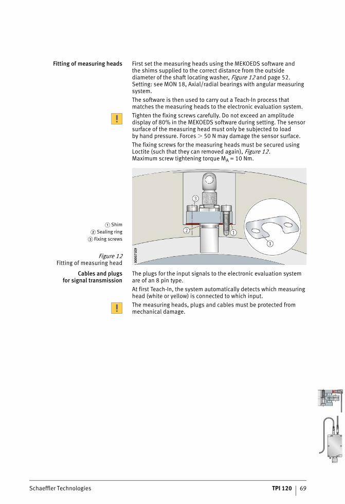
Schaeffler Technologies TPI 120 69
Fitting of measuring heads First set the measuring heads using the MEKOEDS software andthe shims supplied to the correct distance from the outsidediameter of the shaft locating washer, Figure 12 and page 52.Setting: see MON 18, Axial/radial bearings with angular measuring system.The software is then used to carry out a Teach-In process that matches the measuring heads to the electronic evaluation system.Tighten the fixing screws carefully. Do not exceed an amplitude display of 80% in the MEKOEDS software during setting. The sensor surface of the measuring head must only be subjected to loadby hand pressure. Forces � 50 N may damage the sensor surface.The fixing screws for the measuring heads must be secured using Loctite (such that they can removed again), Figure 12.Maximum screw tightening torque MA = 10 Nm.
Cables and plugsfor signal transmission
The plugs for the input signals to the electronic evaluation system are of an 8 pin type.At first Teach-In, the system automatically detects which measuring head (white or yellow) is connected to which input.The measuring heads, plugs and cables must be protected from mechanical damage.
� Shim� Sealing ring
� Fixing screws
Figure 12Fitting of measuring head 00
0071
E900
0071
E9
ST4_9007200957576203_beschreib.fm Seite 69 Freitag, 19. August 2016 7:38 07
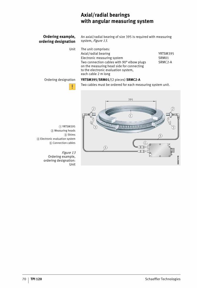
70 TPI 120 Schaeffler Technologies
Axial/radial bearings with angular measuring system
Ordering example,ordering designation
An axial/radial bearing of size 395 is required with measuring system, Figure 13.
Unit The unit comprises:
Ordering designation YRTSM395/SRM01/(2 pieces) SRMC2-ATwo cables must be ordered for each measuring system unit.
Axial/radial bearing YRTSM395Electronic measuring system SRM01Two connection cables with 90° elbow plugson the measuring head side for connectingto the electronic evaluation system,each cable 2 m long
SRMC2-A
� YRTSM395� Measuring heads
� Shims� Electronic evaluation system
� Connection cables
Figure 13Ordering example,
ordering designation:Unit 00
0073
7B00
0073
7B
ST4_9007200957576203_beschreib.fm Seite 70 Freitag, 19. August 2016 7:38 07
Schaeffler Technologies TPI 120 71
Also required... The following are also required:
Ordering designation MEKOEDSThe manuals TPI 103, High precision bearings for combined loads, and MON 18, Axial/radial bearings with angular measuring system, can also be obtained in printed form from Schaeffler.
Replacement parts The following replacement parts are available, Figure 13, page 70:
setting and diagnosis software(USB memory stick with interface cable, 5 m, can be used as often as required)
MEKOEDS
fitting and maintenance manualfor the bearing TPI 103Teach-In and diagnosis manualfor the measuring system MON 18Both manuals are held on the USB memory stick as PDF files.
Only shaft locating washer with coding WSM YRT�bearing bore diameter�
Measuring headwith reference sensor (yellow) SRMH yeMeasuring headwithout reference sensor (white) SRMH whShims (packet) SS-SRMElectronic evaluation system SRMB
ST4_9007200957576203_beschreib.fm Seite 71 Freitag, 19. August 2016 7:38 07
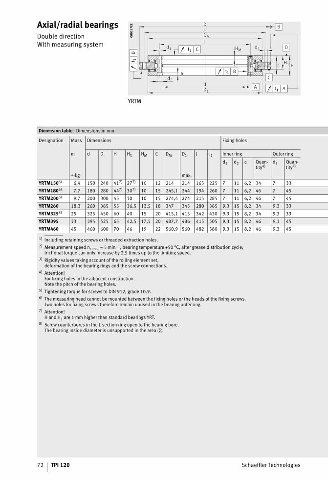
72 TPI 120 Schaeffler Technologies
Axial/radial bearingsDouble directionWith measuring system
YRTM
0001
87EE
0001
87EE
1) Including retaining screws or threaded extraction holes.2) Measurement speed nconst = 5 min–1, bearing temperature +50 °C, after grease distribution cycle;
frictional torque can only increase by 2,5 times up to the limiting speed.3) Rigidity values taking account of the rolling element set,
deformation of the bearing rings and the screw connections.4) Attention!
For fixing holes in the adjacent construction.Note the pitch of the bearing holes.
5) Tightening torque for screws to DIN 912, grade 10.9.6) The measuring head cannot be mounted between the fixing holes or the heads of the fixing screws.
Two holes for fixing screws therefore remain unused in the bearing outer ring.7) Attention!
H and H1 are 1 mm higher than standard bearings YRT.8) Screw counterbores in the L-section ring open to the bearing bore.
The bearing inside diameter is unsupported in the area �.
Dimension table · Dimensions in mm
Designation Mass Dimensions Fixing holes
m d D H H1 HM C DM D1 J J1 Inner ring Outer ring
d1 d2 a Quan-tity4)
d3 Quan-tity4)
�kg max.
YRTM1506) 6,4 150 240 417) 277) 10 12 214 214 165 225 7 11 6,2 34 7 33
YRTM1806) 7,7 180 280 447) 307) 10 15 245,1 244 194 260 7 11 6,2 46 7 45
YRTM2006) 9,7 200 300 45 30 10 15 274,4 274 215 285 7 11 6,2 46 7 45
YRTM260 18,3 260 385 55 36,5 13,5 18 347 345 280 365 9,3 15 8,2 34 9,3 33
YRTM3258) 25 325 450 60 40 15 20 415,1 415 342 430 9,3 15 8,2 34 9,3 33
YRTM395 33 395 525 65 42,5 17,5 20 487,7 486 415 505 9,3 15 8,2 46 9,3 45
YRTM460 45 460 600 70 46 19 22 560,9 560 482 580 9,3 15 8,2 46 9,3 45
ST4_9007200978718859_zweiseiti.fm Seite 72 Freitag, 19. August 2016 7:39 07
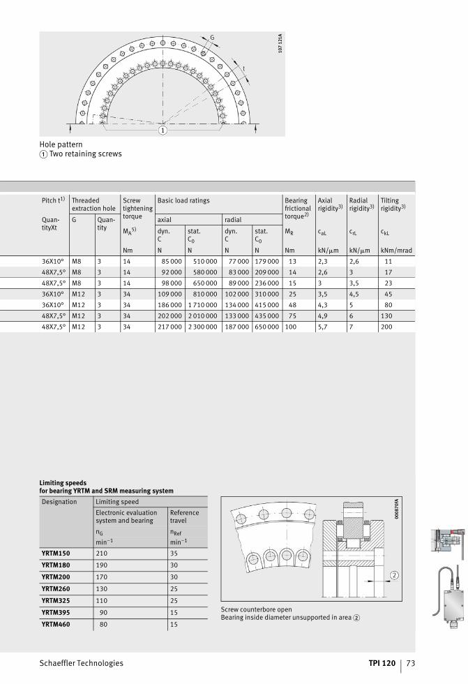
Schaeffler Technologies TPI 120 73
Hole pattern� Two retaining screws
107
121A
107
121A
Pitch t1) Threaded extraction hole
Screw tightening torque
Basic load ratings Bearing frictional torque2)
Axial rigidity3)
Radial rigidity3)
Tilting rigidity3)
Quan-tityXt
G Quan-tity
axial radial
MA5) dyn.
Cstat.C0
dyn.C
stat.C0
MR caL crL ckL
Nm N N N N Nm kN/�m kN/�m kNm/mrad
36X10° M8 3 14 85 000 510 000 77 000 179 000 13 2,3 2,6 11
48X7,5° M8 3 14 92 000 580 000 83 000 209 000 14 2,6 3 17
48X7,5° M8 3 14 98 000 650 000 89 000 236 000 15 3 3,5 23
36X10° M12 3 34 109 000 810 000 102 000 310 000 25 3,5 4,5 45
36X10° M12 3 34 186 000 1 710 000 134 000 415 000 48 4,3 5 80
48X7,5° M12 3 34 202 000 2 010 000 133 000 435 000 75 4,9 6 130
48X7,5° M12 3 34 217 000 2 300 000 187 000 650 000 100 5,7 7 200
Limiting speedsfor bearing YRTM and SRM measuring systemDesignation Limiting speed
Electronic evaluation system and bearing
Referencetravel
nG nRef
min–1 min–1
YRTM150 210 35
YRTM180 190 30
YRTM200 170 30
YRTM260 130 25
YRTM325 110 25
YRTM395 90 15 Screw counterbore openBearing inside diameter unsupported in area �
YRTM460 80 15
0008
70FA
0008
70FA
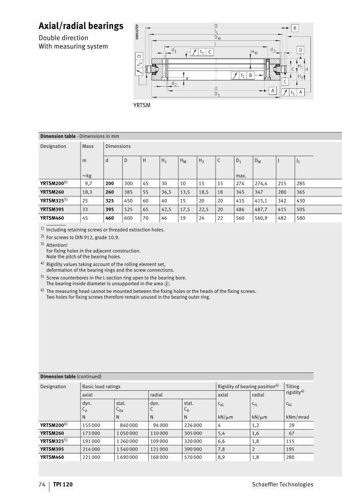
74 TPI 120 Schaeffler Technologies
Axial/radial bearingsDouble directionWith measuring system
YRTSM
0001
67E9
0001
67E9
1) Including retaining screws or threaded extraction holes.2) For screws to DIN 912, grade 10.9.3) Attention!
For fixing holes in the adjacent construction.Note the pitch of the bearing holes.
4) Rigidity values taking account of the rolling element set,deformation of the bearing rings and the screw connections.
5) Screw counterbores in the L-section ring open to the bearing bore.The bearing inside diameter is unsupported in the area �.
6) The measuring head cannot be mounted between the fixing holes or the heads of the fixing screws.Two holes for fixing screws therefore remain unused in the bearing outer ring.
Dimension table · Dimensions in mm
Designation Mass Dimensions
m d D H H1 HM H2 C D1 DM J J1
�kg max.YRTSM2006) 9,7 200 300 45 30 10 15 15 274 274,4 215 285
YRTSM260 18,3 260 385 55 36,5 13,5 18,5 18 345 347 280 365
YRTSM3255) 25 325 450 60 40 15 20 20 415 415,1 342 430
YRTSM395 33 395 525 65 42,5 17,5 22,5 20 486 487,7 415 505
YRTSM460 45 460 600 70 46 19 24 22 560 560,9 482 580
Dimension table (continued)
Designation Basic load ratings Rigidity of bearing position4) Tilting rigidity4)
axial radial axial radial
dyn.Ca
stat.C0a
dyn.C
stat.C0
caL crL ckL
N N N N kN/�m kN/�m kNm/mrad
YRTSM2006) 155 000 840 000 94 000 226 000 4 1,2 29
YRTSM260 173 000 1 050 000 110 000 305 000 5,4 1,6 67
YRTSM3255) 191 000 1 260 000 109 000 320 000 6,6 1,8 115
YRTSM395 214 000 1 540 000 121 000 390 000 7,8 2 195
YRTSM460 221 000 1 690 000 168 000 570 000 8,9 1,8 280
ST4_9007200978718859_zweiseiti.fm Seite 74 Freitag, 19. August 2016 7:39 07
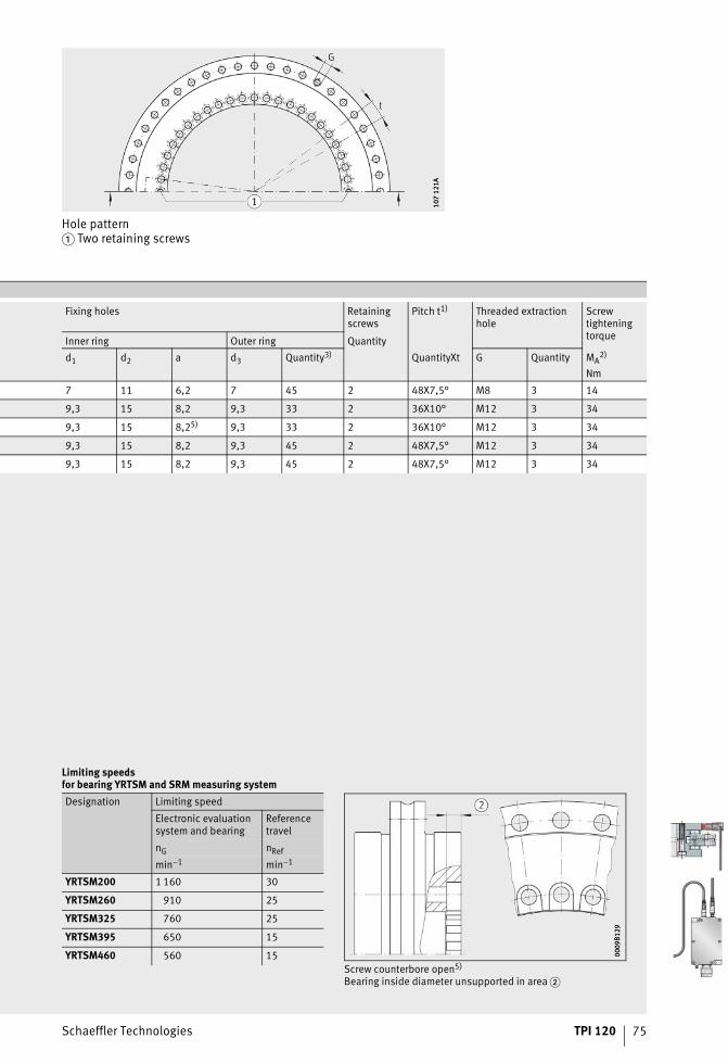
Schaeffler Technologies TPI 120 75
Hole pattern� Two retaining screws
107
121A
107
121A
Fixing holes Retaining screws
Pitch t1) Threaded extraction hole
Screw tightening torqueInner ring Outer ring Quantity
d1 d2 a d3 Quantity3) QuantityXt G Quantity MA2)
Nm
7 11 6,2 7 45 2 48X7,5° M8 3 14
9,3 15 8,2 9,3 33 2 36X10° M12 3 34
9,3 15 8,25) 9,3 33 2 36X10° M12 3 34
9,3 15 8,2 9,3 45 2 48X7,5° M12 3 34
9,3 15 8,2 9,3 45 2 48X7,5° M12 3 34
Limiting speedsfor bearing YRTSM and SRM measuring systemDesignation Limiting speed
Electronic evaluation system and bearing
Reference travel
nG nRef
min–1 min–1
YRTSM200 1 160 30
YRTSM260 910 25
YRTSM325 760 25
YRTSM395 650 15
YRTSM460 560 15Screw counterbore open5)
Bearing inside diameter unsupported in area �
0009
B129
0009
B129
ST4_9007200978718859_zweiseiti.fm Seite 75 Freitag, 19. August 2016 7:39 07

76 TPI 120 Schaeffler Technologies
SRM electronic measuring system
Plug configurationof 12 pin flanged plug
0000
7073
0000
7073
The feeler cables are connected internally to the supply cable (2 with 12 and 11 with 10).They are used by the motor controller as a measurement cable in order to compensate the voltagedrop on the supply cable (four-wire principle). If this function is not supported by the controller used,the two 5-V cables and both 0-V cables can be wired in parallel in order to reduce the voltage drop on the supply lead.The housing is shielded.Electronic evaluation system (protection class IP67):� Connection for RS232� 2 holes for fixing screws DIN 912-M4�10� Shielded plug with cable to electronic post-processing system (not included in delivery).
Plug configuration of 12-pin flanged plug
5 6 8 1 3 4 12 10 2 11 9 7 /
A B R 5 V (UP) 0 V (UN) 5 V (feeler) 0 V (feeler) free / free
+ – + – + – – – – – – – –
– – – – – – IEC 747 EN 50 178 – – – – –
0001
5CED
0001
5CED
ST4_9007200978720395_srm_messe.fm Seite 76 Freitag, 19. August 2016 7:39 07
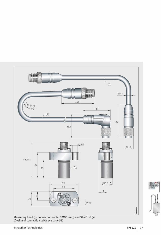
Schaeffler Technologies TPI 120 77
Measuring head �, connection cable SRMC..-A � and SRMC..-S �.(Design of connection cable see page 51)
0009
B805
0009
B805
ST4_9007200978720395_srm_messe.fm Seite 77 Freitag, 19. August 2016 7:39 07
78 TPI 120 Schaeffler Technologies
Further information
Double row axial/radial bearings YRTMA
Internet www.schaeffler.com/machine-tools
Axial Radial Bearingswith Absolute Value Angular Measuring System for Machine Tools■ Special publication SSD 30.
Torque motors from INA – Drives & Mechatronics AG & Co. KG: dynamic and efficient
e-mail [email protected] www.idam.de
RDDMRotary Direct Drive MotorsRI/RE series
RDDMRotary Direct Drive MotorsRIB series
RDDMRotary Direct Drive MotorsRKI series
Media Library
Download and ordering:http://medien.schaeffler.com


Schaeffler TechnologiesAG & Co. KG
Industriestraße 1–391074 HerzogenaurachGermanyInternet www.schaeffler.de/enE-mail [email protected]
In Germany:Phone 0180 5003872Fax 0180 5003873
From other countries:Phone +49 9132 82-0Fax +49 9132 82-4950
Schaeffler TechnologiesAG & Co. KG
Georg-Schäfer-Straße 3097421 SchweinfurtGermanyInternet www.schaeffler.de/enE-mail [email protected]
In Germany:Phone 0180 5003872Fax 0180 5003873
From other countries:Phone +49 9721 91-0Fax +49 9721 91-3435
Every care has been taken to ensure the
correctness of the information contained
in this publication but no liability can
be accepted for any errors or omissions.
We reserve the right to make technical
changes.
© Schaeffler Technologies AG & Co. KG
Issued: 2016, October
This publication or parts thereof may not
be reproduced without our permission.
TPI 120 GB-DMAT
NR
0290
9748
7-00
00 /
TPI
120
/ 0
3 /
GB-
D /
201
610
/ pd
f onl
y