Super preciSion BearingS - SM Industrial · PDF fileUltra High-Speed Angular Contact Ball...
21
SUPER PRECISION BEARINGS
Transcript of Super preciSion BearingS - SM Industrial · PDF fileUltra High-Speed Angular Contact Ball...

Sup
er p
rec
iSion
Bea
rin
gS
Every care has been taken to ensure the infor ma-tion in this publication is accurate but no liability can be accepted for any errors or omissions.
© Copyright NSK 2009. The contents of this publication are the copyright of the publishers. Printed in Germany. Ref: SPB/A/E/07.09
Please also visit our website: www.nskeurope.com – Global NSK: www.nsk.com
EUROPEAN NSK SALES OFFICES
FRANCENSK France S.A.S. Quartier de l’Europe 2, Rue Georges Guynemer 78283 Guyancourt Cedex Tel: +33 1 30573939 Fax: +33 1 30570001 Email: [email protected]
GERMANYNSK Deutschland GmbH Harkortstrasse 15 40880 Ratingen Tel: +49 2102 4810 Fax: +49 2102 4812290 Email: [email protected]
ITALYNSK Italia S.p.A. Via Garibaldi 215 - C.P. 103 20024 Garbagnate Milanese (MI) Tel: +39 02 995191 Fax: +39 02 99025778 Email: [email protected]
NORWAYNORdIC SALES OFFICENSK Europe Norwegian Branch NUF Østre Kullerød 5 N-3241 Sandefjord Tel: +47 33 293160Fax: +47 33 429002 Email: [email protected]
POLANd & CEENSK Polska Sp. z o.o. Warsaw Branch Ul. Migdałowa 4/73 02-796 Warszawa Tel: +48 22 6451525 Fax: +48 22 6451529 Email: [email protected]
SPAINNSK Spain, S.A. C/ Tarragona, 161 Cuerpo Bajo 2a Planta, 08014 BarcelonaTel: +34 93 2892763 Fax: +34 93 4335776 Email: [email protected]
SWEdENNSK Sweden Office Karolinen Företagscenter Våxnäsgatan 10 SE-65340 Karlstad Tel: +46 5410 3545 Fax: +46 5410 3544 Email: [email protected]
TURKEYNSK Rulmanlari Orta Dogu Tic. Ltd. Sti 19 Mayis Mah. Atatürk Cad.Ulya Engın Is Merkezı No: 68 Kat. 6P.K.: 34734 Kozyatagi - IstanbulTel: +90 216 3550398 Fax: +90 216 3550399 Email: [email protected]
UKNSK UK Ltd. Northern Road, Newark Nottinghamshire NG24 2JFTel: +44 1636 605123 Fax: +44 1636 602775Email: [email protected]
Super preciSion BearingS

1. ANGULAR CONTACT BALL BEARINGS
4746
1High Precision Angular Contact Ball Bearings (Standard Series)…P48-60
Features
Numbering System
Bearing Tables
Miniature Series, BSA Series for Ball Screw Support
79 Series
70 Series
72 Series
Ultra High-Speed Angular Contact Ball Bearings (ROBUST Series)…P62-79
Features
Numbering System
Bearing Tables
BNR19, BER19 Series
BNR10, BER10 Series
BNR19XE/10XE, BER19XE/10XE Series (Spinshot™ II)
BNR29, BER29 Series (Wide Series)
BNR20, BER20 Series (Wide Series)
Ultra High Precision Angular Contact Ball Bearings (ROBUST Series—BGR)…P80-84
Features
Numbering System
Bearing Tables
BGR19 Series
BGR10 Series
BGR02 Series
Angular Contact Ball Bearings
Angular Contact Ball Bearings
High Precision Angular Contact Ball Bearings
Standard Series
ROBUST Series
SpinshotTM IIII
Ultra High-Speed Angular Contact Ball Bearings
Ultra High-Speed Angular Contact Ball Bearings
BGR Series
Ultra High Precision Angular Contact Ball Bearings
An
gu
lar
Co
nta
ctB
allB
eari
ng
s
Part 4

Part 1 Part 2 Part 3 Part 4 Part 5 Part 6 Part 7 Part 8
48 49
1. ANGULAR CONTACT BALL BEARINGSHigh Precision Angular Contact Ball Bearings (Standard Series)
30˚ contact angle
15˚
Contact point
Contact point
15˚ contact angle
Ball diameter
30˚
Load acting onrolling element
Number of balls
aF
aF
a /F
Load acting onrolling element
Number of balls a /F
FeaturesSingle-row angular contact ball bearings have a line connectingthe contact points drawn in the radial direction, which is calledthe contact angle. The contact angle makes this bearingsuitable for accommodating radial loads, single direction axialloads, and a combination of both. Furthermore, since an axialcomponent is generated when a radial load is applied, thesebearings are generally used in pairs, triplex sets, quadruplexsets, or multiplex sets.
Contact angle
Effective load center aF
rFContact Angle
Fig. 1.2When a load is applied to an angular contact ball bearing,elastic deformation and the amount of stress at the contactpoint changes as a result of the varying load conditions of theballs, inner ring, and outer ring according to the contact angleof the bearing.
Figure 1.2 illustrates loads acting on two rolling elements for a30˚ contact angle, and a 15˚ contact angle. The relationbetween an axial load being applied to the bearing and resultingload acting on the rolling element can be formulated as:
Fa/(Number of balls × sinα).
Therefore, the larger the contact angle, the smaller the loadacting on the rolling element. Load at the contact point, and itsconsequential deformation, is reduced thus resulting in longerlife. When a radial load is applied, the smaller the contactangle, the smaller the load acting on the rolling element, thusresulting in reduced load at the contact point.
(See Pages 42 and 43 for contact angle specifics.)
Dimension Series
Numbering System of High Precision Angular Contact Ball Bearings (Standard Series)
7 Bearing type 7: single-row angular contact ball bearing 42-43, 48
0 Dimension 9: 19 series, 0: 10 series, 2: 02 series 42-43, 48
C Contact angle C: 15˚, A5: 25˚, A: 30˚ 42-43, 48
Material No symbol: bearing steel (SUJ2) SN24: ceramic ball (Si3N4) ( 1) 14-17
13 Bore numberLess than 03, Bearing bore 00: 10 mm, 01: 12 mm 02: 15 mm, 03: 17 mm
50-60Over 04, Bearing bore Bore number × 5 (mm)
TYN CageTYN: ball guided polyamide resin cage; limiting speed dmn = 1 400 000; operational temperature limit = 120˚C
18-19TR: outer ring guided phenolic resin cage; operational temperature limit = 120˚C
Seal No symbol: open type V1V: non-contact rubber seal ( 2) 32
L PreloadEL: extra light preload, L: light preload, M: medium preload, H: heavy preload 42-43
CP: special preload, CA: special axial clearance 152-160
DB Arrangement
SU: universal arrangement (single row) DU: universal arrangement (double row)42-43
DB: Back-to-back arrangement DF: Face-to-face arrangement DT: tandem arrangement
DBD, DFD, DTD, DUD: triplex set arrangement • DBB, DFF, DBT, DFT, DTT, QU: quadruplex set arrangement148-151
P4 Accuracy
P2: ISO Class 2, P4: ISO Class 4, P5: ISO Class 5151
P3: special class (dimensional accuracy: ISO Class 4; rotating accuracy: ISO Class 2)176-179
P4Y: special class (Bore diameter and outside diameter are exclusive to NSK. All others are ISO Class 4.)
(Bearing number example)
Bearing type symbol
Dimension symbol
Bore number
Contact angle symbol
Material symbol
Accuracy symbol
Preload symbol
Arrangement symbol
Seal symbol
Cage symbol
7 0 13 C TYN DB L P4
Reference pages
72 70 79
Sta
nd
ard
Angu
larC
onta
ctBa
llBe
arin
gs
Fig. 1.3
(1) Angular contact ceramic ball bearing correspondence numbers 79, 70: Bore diameter= φ 10-100 mm.(2) Sealed angular contact ball bearings are standardized for SU arrangement and ISO Class 3.
Sealed angular contact ball bearing correspondence numbers 79, 70: Bore diameter= φ 30-100 mm.
Fig. 1.1

51
Part 1 Part 2 Part 3 Part 4 Part 5 Part 6 Part 7 Part 81. ANGULAR CONTACT BALL BEARINGS
50
70 Series72 Series
Bore Diameter 5-8 mm79 Series
Bore Diameter 10-55 mm
a
B
D d
r
r1r
r
φφ
High Precision Angular Contact Ball Bearings (Miniature Series) High Precision Angular Contact Ball Bearings (Standard Series)
Boundary Dimensions Basic Load Ratings Permissible Effective Load Mass Limiting Speeds (2)Bearing (mm) (kN) Axial Center (g) (min–1)
Numbersd D B
r r1 Cr C0r Load (1) (mm) (approx) Grease Oil(min) (min) (Dynamic) (Static) (kN) a
725C 5 16 5 0.3 0.15 1.700 0.660 0.545 3.91 4.5 110 000 167 000
725A 5 16 5 0.3 0.15 1.610 0.620 0.665 5.53 4.5 72 000 96 000
706C 6 17 6 0.3 0.15 2.150 0.845 0.765 4.54 5.5 100 000 153 000
706A 6 17 6 0.3 0.15 2.030 0.795 0.725 6.32 5.5 66 000 87 000
726C 6 19 6 0.3 0.15 2.390 1.000 0.835 4.67 7.8 92 000 140 000
726A 6 19 6 0.3 0.15 2.240 0.940 0.395 6.61 7.8 60 000 80 000
707C 7 19 6 0.3 0.15 2.390 1.000 0.835 4.67 7.4 89 000 135 000
707A 7 19 6 0.3 0.15 2.240 0.940 0.375 6.61 7.4 58 000 77 000
708C 8 22 7 0.3 0.15 3.550 1.540 1.300 5.51 12.0 77 000 117 000
708A 8 22 7 0.3 0.15 3.350 1.450 1.020 7.84 12.0 50 000 67 000
728C 8 24 8 0.3 0.15 3.600 1.580 1.330 6.14 16.0 72 000 110 000
728A 8 24 8 0.3 0.15 3.350 1.480 0.610 8.62 16.0 47 000 63 000
(1) For permissible axial load, please refer to Page 147.(2) For application of limiting speeds, please refer to Page 170. When a ceramic ball is used, limiting speed value will be 1.25 times the value of steel ball.Note: Bearing numbers with a “C” suffix: nominal contact angle 15˚
Bearing numbers with an “A5” suffix: nominal contact angle 25˚
10 SeriesBore Diameter 8-15 mm
a
B
rr
rr1
dφ
Dφ
High Precision Angular Contact Ball Bearings(BSA Series for ball screw support)
Boundary Dimensions Basic Load Ratings Permissible Effective Load Mass Limiting Speeds (2)Bearing (mm) (kN) Axial Center (g) (min–1)
Numbersd D B
r r1 Cr Cor Load (1) (mm) (approx) Grease(min) (min) (Dynamic) (Static) (kN) a
8BSA10T1X 8 22 7 0.3 0.15 2.350 0.840 0.805 12.2 11.0 40 000
10BSA10T1X 10 26 8 0.3 0.15 3.250 1.200 0.960 14.4 16.6 33 300
12BSA10T1X 12 28 9 0.3 0.15 3.600 1.430 1.710 16.0 18.7 30 000
15BSA10T1X 15 32 10 0.3 0.15 3.900 1.690 1.950 18.6 27.7 25 500
For additional information:● Dynamic equivalent load ……………………139
● Static equivalent load …………………………146
● Preload and rigidity……………………………152
● Abutment and fillet dimensions………………186
● Nozzle position…………………………………192
● Quantity of packed grease……………………175
Page No.
Sta
nd
ard
Angu
larC
onta
ctBa
llBe
arin
gs
Boundary Dimensions Basic Load Ratings PermissibleFactor
Effective Load Mass Limiting Speeds (2)Bearing (mm) (kN) Axial Center (kg) Sealed (min–1)
Numbersd D B
r r1 Cr C0r Load (1) fo (mm) (approx) DesignGrease Oil(min) (min) (Dynamic) (Static) (kN) a
7900C 10 22 6 0.3 0.15 3.00 1.52 1.23 14.1 5.1 0.010 – 71 900 109 400
7900A5 10 22 6 0.3 0.15 2.88 1.45 1.44 – 6.7 0.009 – 62 500 93 800
7901C 12 24 6 0.3 0.15 3.35 1.86 1.45 14.7 5.4 0.011 – 63 900 97 300
7901A5 12 24 6 0.3 0.15 3.20 1.77 1.71 – 7.2 0.011 – 55 600 83 400
7902C 15 28 7 0.3 0.15 4.75 2.64 1.93 14.5 6.4 0.016 – 53 500 81 400
7902A5 15 28 7 0.3 0.15 4.55 2.53 2.22 – 8.5 0.016 – 46 600 69 800
7903C 17 30 7 0.3 0.15 5.00 2.94 2.09 14.8 6.6 0.017 – 49 000 74 500
7903A5 17 30 7 0.3 0.15 4.75 2.80 2.21 – 9.0 0.017 – 42 600 63 900
7904C 20 37 9 0.3 0.15 6.95 4.25 3.20 14.9 8.3 0.036 – 40 400 61 500
7904A5 20 37 9 0.3 0.15 6.60 4.05 3.55 – 11.1 0.037 – 35 100 52 700
7905C 25 42 9 0.3 0.15 7.85 5.40 3.90 15.5 9.0 0.043 – 34 400 52 300
7905A5 25 42 9 0.3 0.15 7.45 5.15 4.40 – 12.3 0.043 – 29 900 44 800
7906C 30 47 9 0.3 0.15 8.30 6.25 4.40 15.9 9.7 0.049 29 900 45 500
7906A5 30 47 9 0.3 0.15 7.85 5.95 4.95 – 13.5 0.050 26 000 39 000
7907C 35 55 10 0.6 0.3 12.1 9.15 6.60 15.7 11.0 0.074 25 600 38 900
7907A5 35 55 10 0.6 0.3 11.4 8.70 7.20 – 15.5 0.075 22 300 33 400
7908C 40 62 12 0.6 0.3 15.1 11.7 8.40 15.7 12.8 0.109 22 600 34 400
7908A5 40 62 12 0.6 0.3 14.3 11.2 8.90 – 17.9 0.110 19 700 29 500
7909C 45 68 12 0.6 0.3 16.0 13.4 8.55 16.0 13.6 0.129 20 400 31 000
7909A5 45 68 12 0.6 0.3 15.1 12.7 9.95 – 19.2 0.130 17 700 26 600
7910C 50 72 12 0.6 0.3 16.9 15.0 9.45 16.2 14.2 0.130 18 900 28 700
7910A5 50 72 12 0.6 0.3 15.9 14.2 11.0 – 20.2 0.132 16 400 24 600
7911C 55 80 13 1.0 0.6 19.1 17.7 11.0 16.3 15.5 0.182 17 100 26 000
7911A5 55 80 13 1.0 0.6 18.1 16.8 12.5 – 22.2 0.184 14 900 22 300
(1) For permissible axial load, please refer to Page 147.(2) For application of limiting speeds, please refer to Page 170. When a ceramic ball is used, limiting speed value will be 1.25 times the value of steel ball.Note: Bearing type BSA: nominal contact angle 30˚
(1) For permissible axial load, please refer to Page 147.(2) For application of limiting speeds, please refer to Page 170. When a ceramic ball is used, limiting speed value will be 1.25 times the value of steel ball.Note: Bearing numbers with a “C” suffix: nominal contact angle 15˚
Bearing numbers with an “A” suffix: nominal contact angle 30˚

Part 1 Part 2 Part 3 Part 4 Part 5 Part 6 Part 7 Part 8
5352
1. ANGULAR CONTACT BALL BEARINGSHigh Precision Angular Contact Ball Bearings (Standard Series)
79 SeriesBore Diameter 60-280 mm
a
Dd
r r
Br1r
φφ
79 Series (continued)
(1) For permissible axial load, please refer to Page 147.(2) For application of limiting speeds, please refer to Page 170.Note: Bearing numbers with a “C” suffix: nominal contact angle 15˚
Bearing numbers with an “A5” suffix: nominal contact angle 25˚
For additional information:● Dynamic equivalent load ……………………139
● Static equivalent load …………………………146
● Preload and rigidity……………………………152
● Abutment and fillet dimensions………………186
● Nozzle position…………………………………192
● Quantity of packed grease……………………175
Page No.
Sta
nd
ard
Angu
larC
onta
ctBa
llBe
arin
gs
(1) For permissible axial load, please refer to Page 147.(2) For application of limiting speeds, please refer to Page 170.
When a ceramic ball is used, limiting speed value will be 1.25 times the value of steel ball.Note: Bearing numbers with a “C” suffix: nominal contact angle 15˚
Bearing numbers with an “A5” suffix: nominal contact angle 25˚
Boundary Dimensions Basic Load Ratings PermissibleFactor
Effective Load Mass Limiting Speeds (2)Bearing (mm) (kN) Axial Center (kg) Sealed (min–1)
Numbersd D B
r r1 Cr C0r Load (1) fo (mm) (approx) DesignGrease Oil(min) (min) (Dynamic) (Static) (kN) a
7912C 60 85 13 1.0 0.6 19.4 18.7 11.5 16.5 16.2 0.195 15 900 24 200
7912A5 60 85 13 1.0 0.6 18.3 17.7 13.0 – 23.4 0.198 13 800 20 700
7913C 65 90 13 1.0 0.6 20.2 20.5 12.5 16.7 16.9 0.208 14 900 22 600
7913A5 65 90 13 1.0 0.6 19.1 19.4 14.2 – 24.6 0.211 13 000 19 400
7914C 70 100 16 1.0 0.6 28.1 27.8 17.3 16.4 19.4 0.338 13 600 20 600
7914A5 70 100 16 1.0 0.6 26.5 26.3 20.3 – 27.8 0.341 11 800 17 700
7915C 75 105 16 1.0 0.6 28.6 29.3 18.0 16.6 20.1 0.358 12 800 19 500
7915A5 75 105 16 1.0 0.6 26.9 27.7 21.2 – 29.0 0.355 11 200 16 700
7916C 80 110 16 1.0 0.6 29.0 30.5 18.7 16.7 20.7 0.377 12 200 18 500
7916A5 80 110 16 1.0 0.6 27.3 29.0 22.1 – 30.2 0.381 10 600 15 800
7917C 85 120 18 1.1 0.6 39.0 40.5 25.9 16.5 22.7 0.534 11 300 17 100
7917A5 85 120 18 1.1 0.6 36.5 38.5 30.0 – 32.9 0.541 9 800 14 700
7918C 90 125 18 1.1 0.6 41.5 46.0 29.1 16.6 23.4 0.568 10 700 16 300
7918A5 90 125 18 1.1 0.6 39.5 43.5 33.5 – 34.1 0.560 9 400 14 000
7919C 95 130 18 1.1 0.6 42.5 48.0 30.0 16.7 24.1 0.597 10 300 15 600
7919A5 95 130 18 1.1 0.6 40.0 45.5 35.0 – 35.2 0.603 8 900 13 400
7920C 100 140 20 1.1 0.6 50.0 54.0 33.0 16.5 26.1 0.800 9 600 14 600
7920A5 100 140 20 1.1 0.6 47.5 51.5 39.5 – 38.0 0.808 8 400 12 500
7921C 105 145 20 1.1 0.6 51.0 57.0 34.5 16.6 26.7 0.831 – 9 200 14 000
7921A5 105 145 20 1.1 0.6 48.0 54.0 41.0 – 39.2 0.820 – 8 000 12 000
7922C 110 150 20 1.1 0.6 52.0 59.5 35.5 16.7 27.4 0.867 – 8 900 13 500
7922A5 110 150 20 1.1 0.6 49.0 56.0 43.0 – 40.3 0.877 – 7 700 11 600
7924C 120 165 22 1.1 0.6 72.0 81.0 50.5 16.5 30.1 1.160 – 8 100 12 300
7924A5 120 165 22 1.1 0.6 67.5 77.0 59.5 – 44.2 1.150 – 7 100 10 600
Boundary Dimensions Basic Load Ratings PermissibleFactor
Effective Load Mass Limiting Speeds (2)Bearing (mm) (kN) Axial Center (kg) Sealed (min–1)
Numbersd D B
r r1 Cr C0r Load (1) fo (mm) (approx) DesignGrease Oil(min) (min) (Dynamic) (Static) (kN) a
7926C 130 180 24 1.5 1.0 78.5 91.0 55.0 16.5 32.8 1.500 – 7 500 11 300
7926A5 130 180 24 1.5 1.0 74.0 86.0 63.5 – 48.1 1.540 – 6 500 9 700
7928C 140 190 24 1.5 1.0 79.5 95.5 58.0 16.7 34.1 1.630 – 7 000 10 700
7928A5 140 190 24 1.5 1.0 75.0 90.0 68.0 – 50.5 1.630 – 6 100 9 100
7930C 150 210 28 2.0 1.0 102 122 74.0 16.6 38.1 2.960 – 6 400 9 800
7930A5 150 210 28 2.0 1.0 96.5 115 84.5 – 56.0 2.970 – 5 600 8 400
7932C 160 220 28 2.0 1.0 106 133 80.0 16.7 39.4 3.100 – 6 100 9 300
7932A5 160 220 28 2.0 1.0 100 125 93.5 – 58.3 3.120 – 5 300 7 900
7934C 170 230 28 2.0 1.0 113 148 88.5 16.8 40.8 3.360 – 5 800 8 800
7934A5 170 230 28 2.0 1.0 106 140 103 – 60.6 3.360 – 5 000 7 500
7936C 180 250 33 2.0 1.0 145 184 111 16.6 45.3 4.900 – 5 400 8 200
7936A5 180 250 33 2.0 1.0 137 174 127 – 66.6 4.940 – 4 700 7 000
7938C 190 260 33 2.0 1.0 147 192 115 16.7 46.6 4.980 – 5 200 7 800
7938A5 190 260 33 2.0 1.0 139 182 131 – 69.0 5.120 – 4 500 6 700
7940C 200 280 38 2.1 1.1 189 244 144 16.5 51.2 6.850 – 4 800 7 300
7940A5 200 280 38 2.1 1.1 178 231 169 – 75.0 6.920 – 4 200 6 300
7944C 220 300 38 2.1 1.1 190 256 235 16.7 53.8 6.665 – 4 500 6 800
7944A5 220 300 38 2.1 1.1 179 242 174 – 79.6 6.665 – 3 900 5 800
7948C 240 320 38 2.1 1.1 200 286 260 16.8 56.5 7.224 – 4 200 6 300
7948A5 240 320 38 2.1 1.1 189 270 193 – 84.3 7.224 – 3 600 5 400
7952C 260 360 46 2.1 1.1 256 365 340 16.6 64.5 11.936 – 3 800 5 700
7952A5 260 360 46 2.1 1.1 241 345 252 – 95.3 11.936 – 3 300 4 900
7956C 280 380 46 2.1 1.1 272 410 380 16.7 67.2 12.853 – 3 500 5 400
7956A5 280 380 46 2.1 1.1 256 390 283 – 99.9 12.853 – 3 100 4 600

Part 1 Part 2 Part 3 Part 4 Part 5 Part 6 Part 7 Part 8
54 55
1. ANGULAR CONTACT BALL BEARINGS
a
B
D
d
r r
r1r
φ
φ
High Precision Angular Contact Ball Bearings (Standard Series)
70 SeriesBore Diameter 10-75 mm
(1) For permissible axial load, please refer to Page 147.(2) For application of limiting speeds, please refer to Page 170.
When a ceramic ball is used, limiting speed value will be 1.25 times the value of steel ball.Note: Bearing numbers with a “C” suffix: nominal contact angle 15˚
Bearing numbers with an “A5” suffix: nominal contact angle 25˚Bearing numbers with an “A” suffix: nominal contact angle 30˚
70 Series (continued)
(1) For permissible axial load, please refer to Page 147.(2) For application of limiting speeds, please refer to Page 170.
When a ceramic ball is used, limiting speed value will be 1.25 times the value of steel ball.Note: Bearing numbers with a “C” suffix: nominal contact angle 15˚
Bearing numbers with an “A5” suffix: nominal contact angle 25˚Bearing numbers with an “A” suffix: nominal contact angle 30˚
For additional information:● Dynamic equivalent load ……………………139
● Static equivalent load …………………………146
● Preload and rigidity……………………………152
● Abutment and fillet dimensions………………186
● Nozzle position…………………………………192
● Quantity of packed grease……………………175
Page No.
Sta
nd
ard
Angu
larC
onta
ctBa
llBe
arin
gs
Boundary Dimensions Basic Load Ratings PermissibleFactor
Effective Load Mass Limiting Speeds (2)Bearing (mm) (kN) Axial Center (kg) Sealed (min–1)
Numbersd D B
r r1 Cr C0r Load (1) fo (mm) (approx) DesignGrease Oil(min) (min) (Dynamic) (Static) (kN) a
7000C 10 26 8 0.3 0.15 5.30 2.49 2.16 12.6 6.4 0.019 – 63 900 97 300
7000A5 10 26 8 0.3 0.15 5.15 2.41 2.48 – 8.2 0.019 – 55 600 83 400
7000A 10 26 8 0.3 0.15 5.00 2.34 1.91 – 9.2 0.019 – 41 700 55 600
7001C 12 28 8 0.3 0.15 5.80 2.90 2.40 13.2 6.7 0.021 – 57 500 87 500
7001A5 12 28 8 0.3 0.15 5.60 2.79 2.82 – 8.7 0.021 – 50 000 75 000
7001A 12 28 8 0.3 0.15 5.40 2.71 2.13 – 9.8 0.021 – 37 500 50 000
7002C 15 32 9 0.3 0.15 6.25 3.40 2.63 14.1 7.6 0.030 – 49 000 74 500
7002A5 15 32 9 0.3 0.15 5.95 3.25 3.05 – 10.0 0.030 – 42 600 63 900
7002A 15 32 9 0.3 0.15 5.80 3.15 2.36 – 11.3 0.030 – 32 000 42 600
7003C 17 35 10 0.3 0.15 6.60 3.80 2.85 14.5 8.5 0.039 – 44 300 67 400
7003A5 17 35 10 0.3 0.15 6.30 3.65 3.35 – 11.1 0.040 – 38 500 57 700
7003A 17 35 10 0.3 0.15 6.10 3.50 2.59 – 12.5 0.040 – 28 900 38 500
7004C 20 42 12 0.6 0.3 11.1 6.55 4.80 14.0 10.1 0.067 – 37 100 56 500
7004A5 20 42 12 0.6 0.3 10.6 6.25 5.45 – 13.2 0.067 – 32 300 48 400
7004A 20 42 12 0.6 0.3 10.3 6.10 4.20 – 14.9 0.068 – 24 200 32 300
7005C 25 47 12 0.6 0.3 11.7 7.40 5.20 14.7 10.8 0.078 – 32 000 48 700
7005A5 25 47 12 0.6 0.3 11.1 7.10 5.95 – 14.4 0.077 – 27 800 41 700
7005A 25 47 12 0.6 0.3 10.7 6.85 4.55 – 16.4 0.079 – 20 900 27 800
7006C 30 55 13 1.0 0.6 15.1 10.3 6.85 14.9 12.2 0.114 27 100 41 200
7006A5 30 55 13 1.0 0.6 14.4 9.80 8.05 – 16.4 0.114 23 600 35 300
7006A 30 55 13 1.0 0.6 13.9 9.45 6.20 – 18.8 0.116 17 700 23 600
7007C 35 62 14 1.0 0.6 19.1 13.7 9.35 15.0 13.5 0.151 23 800 36 100
7007A5 35 62 14 1.0 0.6 18.2 13.0 11.4 – 18.3 0.151 20 700 31 000
7007A 35 62 14 1.0 0.6 17.5 12.6 8.75 – 21.0 0.153 15 500 20 700
Boundary Dimensions Basic Load Ratings PermissibleFactor
Effective Load Mass Limiting Speeds (2)Bearing (mm) (kN) Axial Center (kg) Sealed (min–1)
Numbersd D B
r r1 Cr C0r Load (1) fo (mm) (approx) DesignGrease Oil(min) (min) (Dynamic) (Static) (kN) a
7008C 40 68 15 1.0 0.6 20.6 15.9 10.6 15.4 14.7 0.189 21 300 32 500
7008A5 40 68 15 1.0 0.6 19.5 15.1 12.0 – 20.1 0.188 18 600 27 800
7008A 40 68 15 1.0 0.6 18.8 14.6 9.15 – 23.1 0.191 13 900 18 600
7009C 45 75 16 1.0 0.6 24.4 19.3 12.4 15.4 16.0 0.238 19 200 29 200
7009A5 45 75 16 1.0 0.6 23.1 18.3 14.5 – 22.0 0.250 16 700 25 000
7009A 45 75 16 1.0 0.6 22.3 17.7 11.1 – 25.3 0.241 12 500 16 700
7010C 50 80 16 1.0 0.6 26.0 21.9 13.9 15.7 16.7 0.259 17 700 27 000
7010A5 50 80 16 1.0 0.6 24.6 20.8 16.2 – 23.2 0.270 15 400 23 100
7010A 50 80 16 1.0 0.6 23.7 20.1 12.5 – 26.8 0.262 11 600 15 400
7011C 55 90 18 1.1 0.6 34.0 28.6 18.9 15.5 18.7 0.380 15 900 24 200
7011A5 55 90 18 1.1 0.6 32.5 27.2 21.8 – 25.9 0.383 13 800 20 700
7011A 55 90 18 1.1 0.6 31.0 26.3 16.6 – 29.9 0.385 10 400 13 800
7012C 60 95 18 1.1 0.6 35.0 30.5 19.9 15.7 19.4 0.405 14 900 22 600
7012A5 60 95 18 1.1 0.6 33.0 29.1 23.0 – 27.1 0.408 13 000 19 400
7012A 60 95 18 1.1 0.6 32.0 28.1 17.6 – 31.4 0.410 9 700 13 000
7013C 65 100 18 1.1 0.6 37.0 34.5 22.0 15.9 20.0 0.435 14 000 21 300
7013A5 65 100 18 1.1 0.6 35.0 32.5 25.4 – 28.2 0.455 12 200 18 200
7013A 65 100 18 1.1 0.6 33.5 31.5 19.5 – 32.8 0.441 9 100 12 200
7014C 70 110 20 1.1 0.6 47.0 43.0 26.8 15.7 22.1 0.606 12 800 19 500
7014A5 70 110 20 1.1 0.6 44.5 41.0 32.0 – 31.0 0.625 11 200 16 700
7014A 70 110 20 1.1 0.6 42.5 39.5 24.6 – 36.0 0.613 8 400 11 200
7015C 75 115 20 1.1 0.6 48.0 45.5 28.1 15.9 22.7 0.643 12 200 18 500
7015A5 75 115 20 1.1 0.6 45.5 43.5 33.5 – 32.1 0.652 10 600 15 800
7015A 75 115 20 1.1 0.6 43.5 41.5 25.9 – 37.4 0.650 7 900 10 600
Part 1 Part 2 Part 3 Part 4 Part 5 Part 6 Part 7 Part 8
56 57
1. ANGULAR CONTACT BALL BEARINGS
a
B
D
d
r r
r1r
φ
φ
High Precision Angular Contact Ball Bearings (Standard Series)
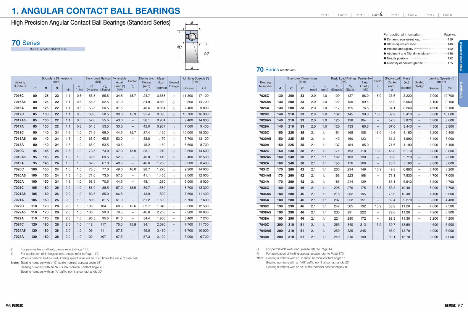
70 SeriesBore Diameter 80-200 mm
(1) For permissible axial load, please refer to Page 147.(2) For application of limiting speeds, please refer to Page 170.
When a ceramic ball is used, limiting speed value will be 1.25 times the value of steel ball.Note: Bearing numbers with a “C” suffix: nominal contact angle 15˚
Bearing numbers with an “A5” suffix: nominal contact angle 25˚Bearing numbers with an “A” suffix: nominal contact angle 30˚
70 Series (continued)
(1) For permissible axial load, please refer to Page 14.(2) For application of limiting speeds, please refer to Page 170.Note: Bearing numbers with a “C” suffix: nominal contact angle 15˚
Bearing numbers with an “A5” suffix: nominal contact angle 25˚Bearing numbers with an “A” suffix: nominal contact angle 30˚
For additional information:● Dynamic equivalent load ……………………139
● Static equivalent load …………………………146
● Preload and rigidity……………………………152
● Abutment and fillet dimensions………………186
● Nozzle position…………………………………192
● Quantity of packed grease……………………175
Page No.
Sta
nd
ard
Angu
larC
onta
ctBa
llBe
arin
gs
Boundary Dimensions Basic Load Ratings PermissibleFactor
Effective Load Mass Limiting Speeds (2)Bearing (mm) (kN) Axial Center (kg) Sealed (min–1)
Numbersd D B
r r1 Cr C0r Load (1) fo (mm) (approx) DesignGrease Oil(min) (min) (Dynamic) (Static) (kN) a
7016C 80 125 22 1.1 0.6 58.5 55.5 34.5 15.7 24.7 0.855 11 300 17 100
7016A5 80 125 22 1.1 0.6 55.5 52.5 41.0 – 34.9 0.880 9 800 14 700
7016A 80 125 22 1.1 0.6 53.5 50.5 31.5 – 40.6 0.864 7 400 9 800
7017C 85 130 22 1.1 0.6 60.0 58.5 38.0 15.9 25.4 0.898 10 700 16 300
7017A5 85 130 22 1.1 0.6 57.0 55.5 43.0 – 36.1 0.904 9 400 14 000
7017A 85 130 22 1.1 0.6 54.5 53.5 33.0 – 42.0 0.907 7 000 9 400
7018C 90 140 24 1.5 1.0 71.5 69.0 44.5 15.7 27.4 1.160 10 000 15 300
7018A5 90 140 24 1.5 1.0 68.0 65.5 52.0 – 38.8 1.170 8 700 13 100
7018A 90 140 24 1.5 1.0 65.0 63.5 40.5 – 45.2 1.180 6 600 8 700
7019C 95 145 24 1.5 1.0 73.5 73.0 47.0 15.9 28.1 1.210 9 600 14 600
7019A5 95 145 24 1.5 1.0 69.5 69.5 52.5 – 40.0 1.410 8 400 12 500
7019A 95 145 24 1.5 1.0 67.0 67.0 40.5 – 46.6 1.230 6 300 8 400
7020C 100 150 24 1.5 1.0 75.5 77.0 49.0 16.0 28.7 1.270 9 200 14 000
7020A5 100 150 24 1.5 1.0 71.0 73.5 57.5 – 41.1 1.450 8 000 12 000
7020A 100 150 24 1.5 1.0 68.5 70.5 44.5 – 48.1 1.280 6 000 8 000
7021C 105 160 26 2.0 1.0 88.0 89.5 57.0 15.9 30.7 1.580 – 8 700 13 300
7021A5 105 160 26 2.0 1.0 83.5 85.0 66.5 – 43.9 1.820 – 7 600 11 400
7021A 105 160 26 2.0 1.0 80.0 81.5 51.0 – 51.2 1.600 – 5 700 7 600
7022C 110 170 28 2.0 1.0 106 104 68.5 15.6 32.7 1.940 – 8 300 12 500
7022A5 110 170 28 2.0 1.0 100 99.0 79.5 – 46.6 2.260 – 7 200 10 800
7022A 110 170 28 2.0 1.0 96.5 95.5 61.0 – 54.4 1.960 – 5 400 7 200
7024C 120 180 28 2.0 1.0 112 117 75.5 15.8 34.1 2.090 – 7 700 11 700
7024A5 120 180 28 2.0 1.0 106 111 87.5 – 49.0 2.430 – 6 700 10 000
7024A 120 180 28 2.0 1.0 102 107 67.5 – 57.3 2.120 – 5 000 6 700
Boundary Dimensions Basic Load Ratings PermissibleFactor
Effective Load Mass Limiting Speeds (2)Bearing (mm) (kN) Axial Center (kg) Sealed (min–1)
Numbersd D B
r r1 Cr C0r Load (1) fo (mm) (approx) DesignGrease Oil(min) (min) (Dynamic) (Static) (kN) a
7026C 130 200 33 2.0 1.0 129 137 86.0 15.9 38.6 3.220 – 7 000 10 700
7026A5 130 200 33 2.0 1.0 122 130 99.5 – 55.0 3.660 – 6 100 9 100
7026A 130 200 33 2.0 1.0 117 125 76.5 – 64.1 3.260 – 4 600 6 100
7028C 140 210 33 2.0 1.0 132 145 90.0 16.0 39.9 3.410 – 6 600 10 000
7028A5 140 210 33 2.0 1.0 125 138 104 – 57.3 3.870 – 5 800 8 600
7028A 140 210 33 2.0 1.0 120 133 80.5 – 67.0 3.440 – 4 300 5 800
7030C 150 225 35 2.1 1.1 151 168 105 16.0 42.6 4.150 – 6 200 9 400
7030A5 150 225 35 2.1 1.1 143 160 123 – 61.2 4.690 – 5 400 8 000
7030A 150 225 35 2.1 1.1 137 154 95.0 – 71.6 4.190 – 4 000 5 400
7032C 160 240 38 2.1 1.1 171 193 118 16.0 45.8 5.110 – 5 800 8 800
7032A5 160 240 38 2.1 1.1 162 183 138 – 65.6 5.710 – 5 000 7 500
7032A 160 240 38 2.1 1.1 155 176 106 – 76.7 5.160 – 3 800 5 000
7034C 170 260 42 2.1 1.1 205 234 149 15.9 49.8 6.880 – 5 400 8 200
7034A5 170 260 42 2.1 1.1 193 223 168 – 71.1 7.830 – 4 700 7 000
7034A 170 260 42 2.1 1.1 186 214 129 – 83.1 6.940 – 3 500 4 700
7036C 180 280 46 2.1 1.1 228 276 175 15.8 53.8 10.40 – 5 000 7 700
7036A5 180 280 46 2.1 1.1 216 262 195 – 76.6 10.40 – 4 400 6 600
7036A 180 280 46 2.1 1.1 207 252 151 – 89.4 9.270 – 3 300 4 400
7038C 190 290 46 2.1 1.1 247 305 192 15.9 55.2 11.20 – 4 800 7 300
7038A5 190 290 46 2.1 1.1 233 291 222 – 79.0 11.20 – 4 200 6 300
7038A 190 290 46 2.1 1.1 224 280 172 – 92.3 11.30 – 3 200 4 200
7040C 200 310 51 2.1 1.1 265 340 213 15.9 59.7 13.60 – 4 600 6 900
7040A5 200 310 51 2.1 1.1 250 325 245 – 85.0 13.70 – 4 000 5 900
7040A 200 310 51 2.1 1.1 240 310 190 – 99.1 13.70 – 3 000 4 000

Part 1 Part 2 Part 3 Part 4 Part 5 Part 6 Part 7 Part 8
5958
7200C 10 30 9 0.6 0.3 5.40 2.61 2.16 13.2 7.2 0.032 57 500 87 500
7200A5 10 30 9 0.6 0.3 5.20 2.51 2.49 – 9.2 0.031 50 000 75 000
7200A 10 30 9 0.6 0.3 5.05 2.44 1.92 – 10.3 0.032 37 500 50 000
7201C 12 32 10 0.6 0.3 7.90 3.85 3.45 12.5 7.9 0.036 52 300 79 600
7201A5 12 32 10 0.6 0.3 7.65 3.70 3.55 – 10.1 0.036 45 500 68 200
7201A 12 32 10 0.6 0.3 7.45 3.65 2.72 – 11.4 0.030 34 100 45 500
7202C 15 35 11 0.6 0.3 8.65 4.55 3.85 13.2 8.8 0.045 46 000 70 000
7202A5 15 35 11 0.6 0.3 8.35 4.35 3.95 – 11.3 0.044 40 000 60 000
7202A 15 35 11 0.6 0.3 8.10 4.25 3.00 – 12.7 0.045 30 000 40 000
7203C 17 40 12 0.6 0.3 10.9 5.85 4.85 13.3 9.8 0.065 40 400 61 500
7203A5 17 40 12 0.6 0.3 10.4 5.60 5.30 – 12.6 0.064 35 100 52 700
7203A 17 40 12 0.6 0.3 10.1 5.45 4.05 – 14.2 0.065 26 400 35 100
7204C 20 47 14 1.0 0.6 14.6 8.05 6.30 13.3 11.5 0.103 34 400 52 300
7204A5 20 47 14 1.0 0.6 14.0 7.75 7.40 – 14.8 0.102 29 900 44 800
7204A 20 47 14 1.0 0.6 13.6 7.55 5.75 – 16.7 0.104 22 400 29 900
7205C 25 52 15 1.0 0.6 16.6 10.2 7.50 14.0 12.7 0.127 29 900 45 500
7205A5 25 52 15 1.0 0.6 15.9 9.80 9.05 – 16.5 0.130 26 000 39 000
7205A 25 52 15 1.0 0.6 15.4 9.45 6.95 – 18.6 0.129 19 500 26 000
7206C 30 62 16 1.0 0.6 23.0 14.7 10.3 13.9 14.2 0.194 25 000 38 100
7206A5 30 62 16 1.0 0.6 22.1 14.1 12.0 – 18.7 0.194 21 800 32 700
7206A 30 62 16 1.0 0.6 21.3 13.6 9.20 – 21.3 0.197 16 400 21 800
7207C 35 72 17 1.1 0.6 30.5 19.9 14.4 13.9 15.7 0.280 21 500 32 800
7207A5 35 72 17 1.1 0.6 29.1 19.1 16.6 – 21.0 0.277 18 700 28 100
7207A 35 72 17 1.1 0.6 28.2 18.5 12.7 – 23.9 0.284 14 100 18 700
7208C 40 80 18 1.1 0.6 36.5 25.2 17.6 14.1 17.0 0.366 19 200 29 200
7208A5 40 80 18 1.1 0.6 34.5 24.1 20.6 – 23.0 0.362 16 700 25 000
7208A 40 80 18 1.1 0.6 33.5 23.3 15.8 – 26.3 0.370 12 500 16 700
7209C 45 85 19 1.1 0.6 41.0 28.8 19.6 14.2 18.2 0.406 17 700 27 000
7209A5 45 85 19 1.1 0.6 39.0 27.6 23.3 – 24.7 0.402 15 400 23 100
7209A 45 85 19 1.1 0.6 37.5 26.7 18.0 – 28.3 0.410 11 600 15 400
7210C 50 90 20 1.1 0.6 43.0 31.5 21.1 14.5 19.4 0.457 16 500 25 000
7210A5 50 90 20 1.1 0.6 41.0 30.5 25.2 – 26.3 0.453 14 300 21 500
7210A 50 90 20 1.1 0.6 39.5 29.3 19.4 – 30.2 0.462 10 800 14 300
7211C 55 100 21 1.5 1.0 53.0 40.0 27.6 14.5 20.9 0.601 14 900 22 600
7211A5 55 100 21 1.5 1.0 50.5 38.0 32.5 – 28.6 0.596 13 000 19 400
7211A 55 100 21 1.5 1.0 49.0 37.0 25.0 – 32.9 0.609 9 700 13 000
7212C 60 110 22 1.5 1.0 64.0 49.0 34.0 14.4 22.4 0.780 13 600 20 600
7212A5 60 110 22 1.5 1.0 61.0 47.0 40.0 – 30.8 0.773 11 800 17 700
7212A 60 110 22 1.5 1.0 59.0 45.5 30.5 – 35.5 0.789 8 900 11 800
7213C 65 120 23 1.5 1.0 73.0 58.5 40.0 14.6 23.9 1.010 12 500 19 000
7213A5 65 120 23 1.5 1.0 69.5 56.0 46.5 – 33.1 1.000 10 900 16 300
7213A 65 120 23 1.5 1.0 67.5 54.0 36.0 – 38.2 1.020 8 200 10 900
7214C 70 125 24 1.5 1.0 79.5 64.5 43.0 14.6 25.1 1.090 11 800 18 000
7214A5 70 125 24 1.5 1.0 76.0 61.5 49.5 – 34.7 1.080 10 300 15 400
7214A 70 125 24 1.5 1.0 73.0 59.5 38.0 – 40.1 1.100 7 700 10 300
7215C 75 130 25 1.5 1.0 83.0 70.0 46.0 14.8 26.2 1.190 11 300 17 100
7215A5 75 130 25 1.5 1.0 79.0 66.5 53.0 – 36.4 1.180 9 800 14 700
7215A 75 130 25 1.5 1.0 76.0 64.5 40.5 – 42.1 1.200 7 400 9 800
7216C 80 140 26 2.0 1.0 93.0 77.5 54.5 14.7 27.7 1.430 10 500 16 000
7216A5 80 140 26 2.0 1.0 88.5 74.0 62.0 – 38.6 1.420 9 100 13 700
7216A 80 140 26 2.0 1.0 85.5 71.5 47.5 – 44.8 1.450 6 900 9 100
7217C 85 150 28 2.0 1.0 107 90.5 60.5 14.7 29.7 1.790 9 800 14 900
7217A5 85 150 28 2.0 1.0 102 86.5 70.0 – 41.4 1.790 8 600 12 800
7217A 85 150 28 2.0 1.0 98.5 83.5 53.5 – 47.9 1.800 6 400 8 600
7218C 90 160 30 2.0 1.0 123 105 72.0 14.6 31.7 2.200 9 200 14 000
7218A5 90 160 30 2.0 1.0 117 100 83.5 – 44.1 2.310 8 000 12 000
7218A 90 160 30 2.0 1.0 113 96.5 64.5 – 51.1 2.230 6 000 8 000
7219C 95 170 32 2.1 1.1 133 112 76.0 14.6 33.7 2.640 8 700 13 300
7219A5 95 170 32 2.1 1.1 127 107 87.0 – 46.9 2.630 7 600 11 400
7219A 95 170 32 2.1 1.1 122 103 67.0 – 54.2 2.670 5 700 7 600
7220C 100 180 34 2.1 1.1 149 127 88.5 14.5 35.7 3.180 8 300 12 500
7220A5 100 180 34 2.1 1.1 142 121 103 – 49.6 3.160 7 200 10 800
7220A 100 180 34 2.1 1.1 137 117 79.5 – 57.4 3.210 5 400 7 200
7221C 105 190 36 2.1 1.1 162 143 97.5 14.5 37.7 3.780 7 800 11 900
7221A5 105 190 36 2.1 1.1 155 137 111 – 52.4 3.770 6 800 10 200
7221A 105 190 36 2.1 1.1 150 132 85.0 – 60.6 3.820 5 100 6 800
a
B
D d
r
r1r
r
φφ
High Precision Angular Contact Ball Bearings (Standard Series)
1. ANGULAR CONTACT BALL BEARINGS
72 SeriesBore Diameter 10-105 mm
Boundary Dimensions Basic Load Ratings PermissibleFactor
Effective Load Mass Limiting Speeds (2)Bearing (mm) (kN) Axial Center (kg) (min–1)
Numbersd D B
r r1 Cr C0r Load (1) fo (mm) (approx) Grease Oil(min) (min) (Dynamic) (Static) (kN) a
(1) For permissible axial load, please refer to Page 147.(2) For application of limiting speeds, please refer to Page 170.Note: Bearing numbers with a “C” suffix: nominal contact angle 15˚
Bearing numbers with an “A5” suffix: nominal contact angle 25˚Bearing numbers with an “A” suffix: nominal contact angle 30˚
Boundary Dimensions Basic Load Ratings PermissibleFactor
Effective Load Mass Limiting Speeds (2)Bearing (mm) (kN) Axial Center (kg) (min–1)
Numbersd D B
r r1 Cr C0r Load (1) fo (mm) (approx) Grease Oil(min) (min) (Dynamic) (Static) (kN) a
72 Series (continued)
(1) For permissible axial load, please refer to Page 147.(2) For application of limiting speeds, please refer to Page 170.Note: Bearing numbers with a “C” suffix: nominal contact angle 15˚
Bearing numbers with an “A5” suffix: nominal contact angle 25˚Bearing numbers with an “A” suffix: nominal contact angle 30˚
For additional information:● Dynamic equivalent load ……………………139
● Static equivalent load …………………………146
● Preload and rigidity……………………………152
● Abutment and fillet dimensions………………186
● Nozzle position…………………………………192
● Quantity of packed grease……………………175
Page No.
Sta
nd
ard
Angu
larC
onta
ctBa
llBe
arin
gs

Part 1 Part 2 Part 3 Part 4 Part 5 Part 6 Part 7 Part 8
6160
1. ANGULAR CONTACT BALL BEARINGS
7222C 110 200 38 2.1 1.1 176 160 108 14.5 39.8 4.450 7 500 11 300
7222A5 110 200 38 2.1 1.1 168 153 126 – 55.1 4.450 6 500 9 700
7222A 110 200 38 2.1 1.1 162 148 97.0 – 63.7 4.490 4 900 6 500
7224C 120 215 40 2.1 1.1 199 192 132 14.6 42.4 5.420 6 900 10 500
7224A5 120 215 40 2.1 1.1 189 184 150 – 59.1 5.420 6 000 9 000
7224A 120 215 40 2.1 1.1 183 177 116 – 68.3 5.450 4 500 6 000
7226C 130 230 40 3.0 1.1 206 209 144 14.9 44.1 6.230 6 400 9 800
7226A5 130 230 40 3.0 1.1 196 199 163 – 62.0 6.220 5 600 8 400
7226A 130 230 40 3.0 1.1 189 193 127 – 72.0 6.280 4 200 5 600
7228C 140 250 42 3.0 1.1 238 254 172 14.8 47.1 7.910 5 900 9 000
7228A5 140 250 42 3.0 1.1 226 242 194 – 66.5 7.910 5 200 7 700
7228A 140 250 42 3.0 1.1 218 234 150 – 77.3 7.970 3 900 5 200
7230C 150 270 45 3.0 1.1 270 305 205 14.7 50.6 11.100 5 500 8 400
7230A5 150 270 45 3.0 1.1 258 290 231 – 71.5 11.100 4 800 7 200
7230A 150 270 45 3.0 1.1 248 280 179 – 83.1 11.200 3 600 4 800
a
B
D d
r
r1r
r
φφ
High Precision Angular Contact Ball Bearings (Standard Series)
72 SeriesBore Diameter 110-150 mm
Boundary Dimensions Basic Load Ratings PermissibleFactor
Effective Load Mass Limiting Speeds (2)Bearing (mm) (kN) Axial Center (kg) (min–1)
Numbersd D B
r r1 Cr C0r Load (1) fo (mm) (approx) Grease Oil(min) (min) (Dynamic) (Static) (kN) a
(1) For permissible axial load, please refer to Page 147.(2) For application of limiting speeds, please refer to Page 170.Note: Bearing numbers with a “C” suffix: nominal contact angle 15˚
Bearing numbers with an “A5” suffix: nominal contact angle 25˚Bearing numbers with an “A” suffix: nominal contact angle 30˚
Sta
nd
ard
Angu
larC
onta
ctBa
llBe
arin
gs

63
Part 1 Part 2 Part 3 Part 4 Part 5 Part 6 Part 7 Part 81. ANGULAR CONTACT BALL BEARINGS
62
Robust design achieved with NSK’s proprietary analytical technology.Optimum design achieved by computer simulation of temperature rise resulting from ball skid.
New SHX steel material provides superior heat and wear resistance.Enhanced service life measures include raising the seizure limit under low lubrication and high-speedoperating conditions.
Dimension Series
OptimumDesign
HighAccuracy
Long Life
Rolling element material can be tailored to match the application.Ceramic balls are used for ROBUST series angular contact ball bearings.
Highly accurate P2 series is available.NSK’s experience and know-how ensure bearing specifications with a high degree of accuracy.
High SpeedCage engineered for high-speed operations.
Benefits of the lightweight, high strength engineered resin cage include heat resistance and high rigidity, makingthis cage indispensable for high-speed applications.
Low NoiseQuieter running high-speed spindle featuring Spinshot TM IIII lubrication system.
Eliminates noise caused by compressed air of the oil-air lubrication system.
Ultra High-Speed Angular Contact Ball Bearings (ROBUST Series)
Fig. 1.4
Features
Spinshot™ II(XE type)
BNR10BER10
BNR19BER19
BNR20BER20 Series
BNR29BER29 Series
RO
BU
ST
Angu
larC
onta
ctBa
llBe
arin
gs
Reference pages
(Bearing number example)
Nominal bearing bore
Bearing type symbol
Dimension symbol
Material symbol
Accuracy symbol
Preload symbol
Arrangement symbol
Cage symbol
Seal symbol
80 BNR 10 EL P4TYN DBBH
80 Nominal bearing bore Bore diameter (mm) 64-79
BNR Bearing type BNR: 18˚ contact angle, BER: 25˚ contact angle 42-43, 48
10 Dimension 10: 10 series, 19: 19 series, 20: 20 series, 29: 29 series (1) 42-43, 62
P2: ISO Class 2, P4: ISO Class 4, P5: ISO Class 5151
P4 Accuracy P3: special class (dimensional accuracy: ISO Class 4; rotating accuracy: ISO Class 2)176-179
P4Y: special class (Bore diameter and outside diameter are exclusive to NSK. All others are ISO Class 4.)
TypeMaterial
Rings Rolling elements
S Bearing steel (SUJ2) Bearing steel (SUJ2)
H Bearing steel (SUJ2) Ceramics (Si3N4)
X Heat resistant steel (SHX) Ceramics (Si3N4)
XE (SpinshotTM II) Heat resistant steel (SHX) Ceramics (Si3N4)
H Material
EL PreloadEL: extra light preload, L: light preload, M: medium preload, H: heavy preload
CP: special preload, CA: special axial clearance
TYN CageTYN: ball guided polyamide resin cage; limiting speed dmn = 1 400 000; operational temperature limit = 120˚C
18-19T: phenolic resin cage with outer ring guide; operational temperature limit = 120˚C
Seal No symbol: open type V1V: non-contact rubber seal (2) 32
DBB Arrangement
SU: universal arrangement (single row) DU: universal arrangement (double row)42-43
DB: Back-to-back arrangement DF: Face-to-face arrangement DT: tandem arrangement148-151
DBD, DFD, DTD, DUD: triplex set arrangement DBB, DFF, DBT, DFT, DTT, QU: quadruplex set arrangement
Numbering System of Ultra High-Speed Angular Contact Ball Bearings (ROBUST Series)
(1) Series 20 and 29 are exclusively for sealed angular contact ball bearings.(2) Sealed angular contact ball bearings are standardized for SU arrangement and ISO Class 3 standards.
Sealed angular contact ball bearings correspondence numbers BNR19, BNR29, BER19, BER29, BNR10, BNR20, BER10 and BER20: Borediameter=φ30–100 mm
14-17
24-25
42-43152-155161-164

Part 1 Part 2 Part 3 Part 4 Part 5 Part 6 Part 7 Part 8
6564
1. ANGULAR CONTACT BALL BEARINGS
a
B
D d
r1 r
r1r
φφ
Ultra High-Speed Angular Contact Ball Bearings (ROBUST Series)
BNR19 SeriesBER19 Series
Bore Diameter 25-80 mm
(1) For permissible axial load, please refer to Page 147.(2) For application of limiting speeds, please refer to Page 170.Note: Bearing type BNR: nominal contact angle 18˚
Bearing type BER: nominal contact angle 25˚
BNR19 Series (continued)BER19
(1) For permissible axial load, please refer to Page 147.(2) For application of limiting speeds, please refer to Page 170.Note: Bearing type BNR: nominal contact angle 18˚
Bearing type BER: nominal contact angle 25˚
For additional information:● Dynamic equivalent load ……………………139
● Static equivalent load …………………………146
● Preload and rigidity……………………………152
● Abutment and fillet dimensions………………186
● Nozzle position…………………………………192
● Quantity of packed grease……………………175
Page No.
RO
BU
ST
Angu
larC
onta
ctBa
llBe
arin
gs
Boundary Dimensions Basic Load Ratings Permissible Effective Load Mass Limiting Speeds (2)Bearing (mm) (kN) Axial Center (kg) Sealed (min–1)
Numbersd D B
r r1 Cr C0r Load (1) (mm) (approx) DesignGrease Oil(min) (min) (Dynamic) (Static) (kN) a
25BNR19S 25 42 9 0.3 0.15 4.95 0.042 – 41 800 59 800
25BNR19H 25 42 9 0.3 0.15 5.95 3.503.25
9.9 0.038 – 53 800 83 600
25BNR19X 25 42 9 0.3 0.15 0.038 – 62 700 98 600
25BER19S 25 42 9 0.3 0.15 5.90 0.042 – 35 900 50 800
25BER19H 25 42 9 0.3 0.15 5.70 3.403.95
12.3 0.038 – 47 800 74 700
25BER19X 25 42 9 0.3 0.15 0.038 – 56 800 89 600
30BNR19S 30 47 9 0.3 0.15 5.75 0.048 36 400 52 000
30BNR19H 30 47 9 0.3 0.15 6.30 4.053.80
10.8 0.043 46 800 72 800
30BNR19X 30 47 9 0.3 0.15 0.043 54 600 85 800
30BER19S 30 47 9 0.3 0.15 6.80 0.048 31 200 44 200
30BER19H 30 47 9 0.3 0.15 6.00 3.904.60
13.5 0.043 41 600 65 000
30BER19X 30 47 9 0.3 0.15 0.043 49 400 78 000
35BNR19S 35 55 10 0.6 0.3 8.55 0.072 31 200 44 500
35BNR19H 35 55 10 0.6 0.3 9.20 6.005.60
12.3 0.063 40 000 62 300
35BNR19X 35 55 10 0.6 0.3 0.063 46 700 73 400
35BER19S 35 55 10 0.6 0.3 10.0 0.072 26 700 37 800
35BER19H 35 55 10 0.6 0.3 8.80 5.756.80
15.5 0.063 35 600 55 600
35BER19X 35 55 10 0.6 0.3 0.063 42 300 66 700
40BNR19S 40 62 12 0.6 0.3 10.8 0.105 27 500 39 300
40BNR19H 40 62 12 0.6 0.3 11.5 7.657.10
14.3 0.092 35 300 55 000
40BNR19X 40 62 12 0.6 0.3 0.092 41 200 64 800
40BER19S 40 62 12 0.6 0.3 12.8 0.105 23 600 33 400
40BER19H 40 62 12 0.6 0.3 11.0 7.358.65
17.9 0.092 31 400 49 100
40BER19X 40 62 12 0.6 0.3 0.092 37 300 58 900
45BNR19S 45 68 12 0.6 0.3 12.4 0.125 24 800 35 400
45BNR19H 45 68 12 0.6 0.3 12.1 8.708.10
15.2 0.111 31 900 49 600
45BNR19X 45 68 12 0.6 0.3 0.111 37 200 58 500
45BER19S 45 68 12 0.6 0.3 14.6 0.125 21 300 30 100
45BER19H 45 68 12 0.6 0.3 11.6 8.359.85
19.2 0.111 28 400 44 300
45BER19X 45 68 12 0.6 0.3 0.111 33 700 53 100
50BNR19S 50 72 12 0.6 0.3 13.9 0.127 23 000 32 800
50BNR19H 50 72 12 0.6 0.3 12.8 9.759.10
15.9 0.111 29 600 46 000
50BNR19X 50 72 12 0.6 0.3 0.111 34 500 54 100
50BER19S 50 72 12 0.6 0.3 16.3 0.127 19 700 27 900
50BER19H 50 72 12 0.6 0.3 12.3 9.3511.0
20.2 0.111 26 300 41 000
50BER19X 50 72 12 0.6 0.3 0.111 31 200 49 200
Boundary Dimensions Basic Load Ratings Permissible Effective Load Mass Limiting Speeds (2)Bearing (mm) (kN) Axial Center (kg) Sealed (min–1)
Numbersd D B
r r1 Cr C0r Load (1) (mm) (approx) DesignGrease Oil(min) (min) (Dynamic) (Static) (kN) a
55BNR19S 55 80 13 1.0 0.6 16.2 0.178 20 800 29 700
55BNR19H 55 80 13 1.0 0.6 14.4 11.410.6
17.5 0.158 26 700 41 500
55BNR19X 55 80 13 1.0 0.6 0.158 31 200 48 900
55BER19S 55 80 13 1.0 0.6 16.1 0.178 17 800 25 200
55BER19H 55 80 13 1.0 0.6 13.8 10.912.9
22.2 0.158 23 800 37 100
55BER19X 55 80 13 1.0 0.6 0.158 28 200 44 500
60BNR19S 60 85 13 1.0 0.6 17.1 0.190 19 400 27 600
60BNR19H 60 85 13 1.0 0.6 14.6 12.011.2
18.3 0.170 24 900 38 700
60BNR19X 60 85 13 1.0 0.6 0.170 29 000 45 600
60BER19S 60 85 13 1.0 0.6 20.1 0.190 16 600 23 500
60BER19H 60 85 13 1.0 0.6 14.0 11.513.6
23.4 0.170 22 100 34 500
60BER19X 60 85 13 1.0 0.6 0.170 26 300 41 400
65BNR19S 65 90 13 1.0 0.6 18.7 0.204 18 100 25 900
65BNR19H 65 90 13 1.0 0.6 15.2 13.212.3
19.1 0.181 23 300 36 200
65BNR19X 65 90 13 1.0 0.6 0.181 27 100 42 600
65BER19S 65 90 13 1.0 0.6 22.1 0.204 15 500 22 000
65BER19H 65 90 13 1.0 0.6 14.5 12.614.9
24.6 0.181 20 700 32 300
65BER19X 65 90 13 1.0 0.6 0.181 24 600 38 800
70BNR19S 70 100 16 1.0 0.6 26.1 0.328 16 500 23 600
70BNR19H 70 100 16 1.0 0.6 21.3 18.117.1
21.8 0.292 21 200 33 000
70BNR19X 70 100 16 1.0 0.6 0.292 24 800 38 900
70BER19S 70 100 16 1.0 0.6 30.5 0.328 14 200 20 000
70BER19H 70 100 16 1.0 0.6 20.4 17.320.7
27.8 0.292 18 900 29 500
70BER19X 70 100 16 1.0 0.6 0.292 22 400 35 300
75BNR19S 75 105 16 1.0 0.6 27.5 0.348 15 600 22 300
75BNR19H 75 105 16 1.0 0.6 21.6 19.018.0
22.6 0.310 20 000 31 200
75BNR19X 75 105 16 1.0 0.6 0.310 23 400 36 700
75BER19S 75 105 16 1.0 0.6 32.5 0.348 13 400 18 900
75BER19H 75 105 16 1.0 0.6 20.7 18.221.7
29.0 0.310 17 800 27 800
75BER19X 75 105 16 1.0 0.6 0.310 21 200 33 400
80BNR19S 80 110 16 1.0 0.6 28.9 0.366 14 800 21 100
80BNR19H 80 110 16 1.0 0.6 22.0 19.918.9
23.4 0.326 19 000 29 500
80BNR19X 80 110 16 1.0 0.6 0.326 22 200 34 800
80BER19S 80 110 16 1.0 0.6 34.0 0.366 12 700 17 900
80BER19H 80 110 16 1.0 0.6 21.0 19.122.8
30.1 0.326 16 900 26 400
80BER19X 80 110 16 1.0 0.6 0.326 20 000 31 600

Part 1 Part 2 Part 3 Part 4 Part 5 Part 6 Part 7 Part 8
6766
1. ANGULAR CONTACT BALL BEARINGSUltra High-Speed Angular Contact Ball Bearings (ROBUST Series)
BNR19 SeriesBER19 Series
Bore Diameter 85-150 mm
(1) For permissible axial load, please refer to Page 147.(2) For application of limiting speeds, please refer to Page 170.Note: Bearing type BNR: nominal contact angle 18˚
Bearing type BER: nominal contact angle 25˚
RO
BU
ST
Angu
larC
onta
ctBa
llBe
arin
gs
Boundary Dimensions Basic Load Ratings Permissible Effective Load Mass Limiting Speeds (2)Bearing (mm) (kN) Axial Center (kg) Sealed (min–1)
Numbersd D B
r r1 Cr C0r Load (1) (mm) (approx) DesignGrease Oil(min) (min) (Dynamic) (Static) (kN) a
a
B
D d
r1 r
r1r
φφ
85BNR19S 85 120 18 1.1 0.6 38.0 0.527 13 700 19 600
85BNR19H 85 120 18 1.1 0.6 29.4 26.324.8
25.7 0.456 17 600 27 400
85BNR19X 85 120 18 1.1 0.6 0.456 20 500 32 200
85BER19S 85 120 18 1.1 0.6 35.5 0.527 11 800 16 600
85BER19H 85 120 18 1.1 0.6 28.1 25.230.0
32.9 0.456 15 700 24 400
85BER19X 85 120 18 1.1 0.6 0.456 18 600 29 300
90BNR19S 90 125 18 1.1 0.6 43.0 0.552 13 100 18 700
90BNR19H 90 125 18 1.1 0.6 31.5 29.728.1
26.5 0.480 16 800 26 100
90BNR19X 90 125 18 1.1 0.6 0.480 19 600 30 700
90BER19S 90 125 18 1.1 0.6 50.5 0.552 11 200 15 900
90BER19H 90 125 18 1.1 0.6 30.0 28.534.0
34.1 0.480 14 900 23 300
90BER19X 90 125 18 1.1 0.6 0.480 17 700 28 000
95BNR19S 95 130 18 1.1 0.6 50.0 0.571 12 500 17 800
95BNR19H 95 130 18 1.1 0.6 32.0 31.032.5
28.3 0.497 16 000 24 900
95BNR19X 95 130 18 1.1 0.6 0.497 18 700 29 400
95BER19S 95 130 18 1.1 0.6 58.5 0.571 10 700 15 200
95BER19H 95 130 18 1.1 0.6 30.5 29.739.5
36.7 0.497 14 300 22 300
95BER19X 95 130 18 1.1 0.6 0.497 16 900 26 700
100BNR19S 100 140 20 1.1 0.6 50.5 0.770 11 700 16 700
100BNR19H 100 140 20 1.1 0.6 38.0 35.033.0
29.5 0.673 15 000 23 400
100BNR19X 100 140 20 1.1 0.6 0.673 17 500 27 500
100BER19S 100 140 20 1.1 0.6 59.5 0.770 10 000 14 200
100BER19H 100 140 20 1.1 0.6 36.0 33.540.0
38.0 0.673 13 400 20 900
100BER19X 100 140 20 1.1 0.6 0.673 15 900 25 000
105BNR19S 105 145 20 1.1 0.6 53.0 0.795 – 11 200 16 000
105BNR19H 105 145 20 1.1 0.6 38.5 36.539.0
31.5 0.693 – 14 400 22 400
105BNR19X 105 145 20 1.1 0.6 0.693 – 16 800 26 400
105BER19S 105 145 20 1.1 0.6 62.0 0.795 – 9 600 13 600
105BER19H 105 145 20 1.1 0.6 37.0 35.042.0
40.9 0.693 – 12 800 20 000
105BER19X 105 145 20 1.1 0.6 0.693 – 15 200 24 000
Boundary Dimensions Basic Load Ratings Permissible Effective Load Mass Limiting Speeds (2)Bearing (mm) (kN) Axial Center (kg) Sealed (min–1)
Numbersd D B
r r1 Cr C0r Load (1) (mm) (approx) DesignGrease Oil(min) (min) (Dynamic) (Static) (kN) a
110BNR19S 110 150 20 1.1 0.6 55.5 0.838 – 10 800 15 400
110BNR19H 110 150 20 1.1 0.6 39.0 38.042.0
31.1 0.733 – 13 900 21 600
110BNR19X 110 150 20 1.1 0.6 0.733 – 16 200 25 400
110BER19S 110 150 20 1.1 0.6 65.0 0.838 – 9 300 13 100
110BER19H 110 150 20 1.1 0.6 37.5 36.544.0
40.3 0.733 – 12 400 19 300
110BER19X 110 150 20 1.1 0.6 0.733 – 14 700 23 100
120BNR19S 120 165 22 1.1 0.6 75.0 1.124 – 9 900 14 100
120BNR19H 120 165 22 1.1 0.6 54.0 52.049.0
34.2 0.949 – 12 700 19 700
120BNR19X 120 165 22 1.1 0.6 0.949 – 14 800 23 200
120BER19S 120 165 22 1.1 0.6 88.0 1.124 – 8 500 12 000
120BER19H 120 165 22 1.1 0.6 51.5 50.059.5
44.2 0.949 – 11 300 17 600
120BER19X 120 165 22 1.1 0.6 0.949 – 13 400 21 100
130BNR19S 130 180 24 1.5 1.0 85.0 1.477 – 9 100 13 000
130BNR19H 130 180 24 1.5 1.059.5 58.5
56.037.2
1.265 – 11 700 18 100
130BER19S 130 180 24 1.5 1.0 100 1.477 – 7 800 11 000
130BER19H 130 180 24 1.5 1.057.0 56.5
67.548.1
1.265 – 10 400 16 200
140BNR19S 140 190 24 1.5 1.0 89.5 1.567 – 8 500 12 200
140BNR19H 140 190 24 1.5 1.060.0 61.5
58.538.8
1.353 – 11 000 17 000
140BER19S 140 190 24 1.5 1.0 105 1.567 – 7 300 10 400
140BER19H 140 190 24 1.5 1.057.5 59.0
70.550.5
1.353 – 9 700 15 200
150BNR19S 150 210 28 2.0 1.0 114 2.459 – 7 800 11 200
150BNR19H 150 210 28 2.0 1.077.0 78.5
75.043.2
2.139 – 10 000 15 600
150BER19S 150 210 28 2.0 1.0 134 2.459 – 6 700 9 500
150BER19H 150 210 28 2.0 1.073.5 75.5
90.555.9
2.139 – 8 900 13 900
BNR19 Series (continued)BER19
(1) For permissible axial load, please refer to Page 147.(2) For application of limiting speeds, please refer to Page 170.Note: Bearing type BNR: nominal contact angle 18˚
Bearing type BER: nominal contact angle 25˚
For additional information:● Dynamic equivalent load ……………………139
● Static equivalent load …………………………146
● Preload and rigidity……………………………152
● Abutment and fillet dimensions………………186
● Nozzle position…………………………………192
● Quantity of packed grease……………………175
Page No.

Part 1 Part 2 Part 3 Part 4 Part 5 Part 6 Part 7 Part 8
6968
a
B
Dd
r
r1r
rφ
φ
1. ANGULAR CONTACT BALL BEARINGSUltra High-Speed Angular Contact Ball Bearings (ROBUST Series)
BNR10 SeriesBER10 Series
Bore Diameter 30-80 mm
RO
BU
ST
Angu
larC
onta
ctBa
llBe
arin
gs
Boundary Dimensions Basic Load Ratings Permissible Effective Load Mass Limiting Speeds (2)Bearing (mm) (kN) Axial Center (kg) Sealed (min–1)
Numbersd D B
r r1 Cr C0r Load (1) (mm) (approx) DesignGrease Oil(min) (min) (Dynamic) (Static) (kN) a
30BNR10S 30 55 13 1.0 0.6 8.20 0.124 33 000 47 100
30BNR10H 30 55 13 1.0 0.6 8.65 5.755.35
13.3 0.116 42 400 65 900
30BNR10X 30 55 13 1.0 0.6 0.116 49 500 77 700
30BER10S 30 55 13 1.0 0.6 9.65 0.124 28 300 40 000
30BER10H 30 55 13 1.0 0.6 8.30 5.506.50
16.3 0.116 37 700 58 900
30BER10X 30 55 13 1.0 0.6 0.116 44 800 70 600
35BNR10S 35 62 14 1.0 0.6 10.2 0.164 28 900 41 300
35BNR10H 35 62 14 1.0 0.6 10.1 7.106.70
14.8 0.154 37 200 57 800
35BNR10X 35 62 14 1.0 0.6 0.154 43 300 68 100
35BER10S 35 62 14 1.0 0.6 12.0 0.164 24 800 35 100
35BER10H 35 62 14 1.0 0.6 9.70 6.858.10
18.2 0.154 33 000 51 600
35BER10X 35 62 14 1.0 0.6 0.154 39 200 61 900
40BNR10S 40 68 15 1.0 0.6 11.5 0.204 26 000 37 100
40BNR10H 40 68 15 1.0 0.6 10.6 7.957.50
16.2 0.193 33 400 51 900
40BNR10X 40 68 15 1.0 0.6 0.193 38 900 61 200
40BER10S 40 68 15 1.0 0.6 13.5 0.204 22 300 31 500
40BER10H 40 68 15 1.0 0.6 10.1 7.659.10
19.9 0.193 29 700 46 300
40BER10X 40 68 15 1.0 0.6 0.193 35 200 55 600
45BNR10S 45 75 16 1.0 0.6 12.7 0.259 23 400 33 400
45BNR10H 45 75 16 1.0 0.6 11.7 9.008.35
17.6 0.246 30 000 46 700
45BNR10X 45 75 16 1.0 0.6 0.246 35 000 55 000
45BER10S 45 75 16 1.0 0.6 15.0 0.259 20 000 28 400
45BER10H 45 75 16 1.0 0.6 11.2 8.6010.1
21.8 0.246 26 700 41 700
45BER10X 45 75 16 1.0 0.6 0.246 31 700 50 000
50BNR10S 50 80 16 1.0 0.6 14.0 0.281 21 600 30 800
50BNR10H 50 80 16 1.0 0.6 12.2 9.909.20
18.4 0.266 27 700 43 100
50BNR10X 50 80 16 1.0 0.6 0.266 32 400 50 800
50BER10S 50 80 16 1.0 0.6 16.5 0.281 18 500 26 200
50BER10H 50 80 16 1.0 0.6 11.6 9.5011.1
23.0 0.266 24 700 38 500
50BER10X 50 80 16 1.0 0.6 0.266 29 300 46 200
(1) For permissible axial load, please refer to Page 147.(2) For application of limiting speeds, please refer to Page 170.Note: Bearing type BNR: nominal contact angle 18˚
Bearing type BER: nominal contact angle 25˚
Boundary Dimensions Basic Load Ratings Permissible Effective Load Mass Limiting Speeds (2)Bearing (mm) (kN) Axial Center (kg) Sealed (min–1)
Numbersd D B
r r1 Cr C0r Load (1) (mm) (approx) DesignGrease Oil(min) (min) (Dynamic) (Static) (kN) a
55BNR10S 55 90 18 1.1 0.6 17.8 0.414 19400 27600
55BNR10H 55 90 18 1.1 0.6 15.1 12.511.7
20.6 0.393 24 900 38 700
55BNR10X 55 90 18 1.1 0.6 0.393 29 000 45 600
55BER10S 55 90 18 1.1 0.6 21.0 0.414 16 600 23 500
55BER10H 55 90 18 1.1 0.6 14.4 12.014.1
25.7 0.393 22 100 34 500
55BER10X 55 90 18 1.1 0.6 0.393 26 300 41 400
60BNR10S 60 95 18 1.1 0.6 19.5 0.443 18 100 25 900
60BNR10H 60 95 18 1.1 0.6 15.6 13.712.8
21.5 0.419 23 300 36 200
60BNR10X 60 95 18 1.1 0.6 0.419 27 100 42 600
60BER10S 60 95 18 1.1 0.6 22.9 0.443 15 500 22 000
60BER10H 60 95 18 1.1 0.6 15.0 13.115.5
26.9 0.419 20 700 32 300
60BER10X 60 95 18 1.1 0.6 0.419 24 600 38 800
65BNR10S 65 100 18 1.1 0.6 21.1 0.472 17 000 24 300
65BNR10H 65 100 18 1.1 0.6 16.2 14.813.9
22.3 0.447 21 900 34 000
65BNR10X 65 100 18 1.1 0.6 0.447 25 500 40 000
65BER10S 65 100 18 1.1 0.6 24.9 0.472 14 600 20 700
65BER10H 65 100 18 1.1 0.6 15.5 14.216.8
28.0 0.447 19 400 30 400
65BER10X 65 100 18 1.1 0.6 0.447 23 100 36 400
70BNR10S 70 110 20 1.1 0.6 28.6 0.645 15 600 22 300
70BNR10H 70 110 20 1.1 0.6 22.3 19.818.8
24.5 0.605 20 000 31 200
70BNR10X 70 110 20 1.1 0.6 0.605 23 400 36 700
70BER10S 70 110 20 1.1 0.6 33.5 0.645 13 400 18 900
70BER10H 70 110 20 1.1 0.6 21.3 18.922.6
30.8 0.605 17 800 27 800
70BER10X 70 110 20 1.1 0.6 0.605 21 200 33 400
75BNR10S 75 115 20 1.1 0.6 30.0 0.679 14 800 21 100
75BNR10H 75 115 20 1.1 0.6 22.6 20.719.7
25.3 0.638 19 000 29 500
75BNR10X 75 115 20 1.1 0.6 0.638 22 200 34 800
75BER10S 75 115 20 1.1 0.6 35.0 0.679 12 700 17 900
75BER10H 75 115 20 1.1 0.6 21.6 19.823.7
31.9 0.638 16 900 26 400
75BER10X 75 115 20 1.1 0.6 0.638 20 000 31 600
80BNR10S 80 125 22 1.1 0.6 35.5 0.921 13 700 19 600
80BNR10H 80 125 22 1.1 0.6 26.5 24.523.4
27.5 0.867 17 600 27 400
80BNR10X 80 125 22 1.1 0.6 0.867 20 500 32 200
80BER10S 80 125 22 1.1 0.6 42.0 0.921 11 800 16 600
80BER10H 80 125 22 1.1 0.6 25.3 23.528.2
34.6 0.867 15 700 24 400
80BER10X 80 125 22 1.1 0.6 0.867 18 600 29 300
BNR10 Series (continued)BER10
(1) For permissible axial load, please refer to Page 147.(2) For application of limiting speeds, please refer to Page 170.Note: Bearing type BNR: nominal contact angle 18˚
Bearing type BER: nominal contact angle 25˚
For additional information:● Dynamic equivalent load ……………………139
● Static equivalent load …………………………146
● Preload and rigidity……………………………152
● Abutment and fillet dimensions………………186
● Nozzle position…………………………………192
● Quantity of packed grease……………………175
Page No.

Part 1 Part 2 Part 3 Part 4 Part 5 Part 6 Part 7 Part 8
7170
a
B
Dd
r
r1r
rφ
φ
1. ANGULAR CONTACT BALL BEARINGSUltra High-Speed Angular Contact Ball Bearings (ROBUST Series)
BNR10 SeriesBER10 Series
Bore Diameter 85-150 mm
BNR10 Series (continued)BER10
RO
BU
ST
Angu
larC
onta
ctBa
llBe
arin
gs
Boundary Dimensions Basic Load Ratings Permissible Effective Load Mass Limiting Speeds (2)Bearing (mm) (kN) Axial Center (kg) Sealed (min–1)
Numbersd D B
r r1 Cr C0r Load (1) (mm) (approx) DesignGrease Oil(min) (min) (Dynamic) (Static) (kN) a
85BNR10S 85 130 22 1.1 0.6 37.5 0.962 13 100 18 700
85BNR10H 85 130 22 1.1 0.6 26.8 25.724.5
28.4 0.906 16 800 26 100
85BNR10X 85 130 22 1.1 0.6 0.906 19 600 30 700
85BER10S 85 130 22 1.1 0.6 43.5 0.962 11 200 15 900
85BER10H 85 130 22 1.1 0.6 25.6 24.629.5
36.1 0.906 14 900 23 300
85BER10X 85 130 22 1.1 0.6 0.906 17 700 28 000
90BNR10S 90 140 24 1.5 1.0 48.0 1.241 12 200 17 400
90BNR10H 90 140 24 1.5 1.0 35.0 33.031.5
30.7 1.155 15 700 24 400
90BNR10X 90 140 24 1.5 1.0 1.155 18 300 28 700
90BER10S 90 140 24 1.5 1.0 56.0 1.241 10 500 14 800
90BER10H 90 140 24 1.5 1.0 33.5 31.538.0
38.8 1.155 14 000 21 800
90BER10X 90 140 24 1.5 1.0 1.155 16 600 26 100
95BNR10S 95 145 24 1.5 1.0 50.0 1.298 11 700 16 700
95BNR10H 95 145 24 1.5 1.0 35.5 34.532.5
31.3 1.209 15 000 23 400
95BNR10X 95 145 24 1.5 1.0 1.209 17 500 27 500
95BER10S 95 145 24 1.5 1.0 58.5 1.298 10 000 14 200
95BER10H 95 145 24 1.5 1.0 34.0 33.039.5
39.7 1.209 13 400 20 900
95BER10X 95 145 24 1.5 1.0 1.209 15 900 25 000
100BNR10S 100 150 24 1.5 1.0 52.0 1.245 11 200 16 000
100BNR10H 100 150 24 1.5 1.0 36.0 36.034.0
32.3 1.253 14 400 22 400
100BNR10X 100 150 24 1.5 1.0 1.253 16 800 26 400
100BER10S 100 150 24 1.5 1.0 61.0 1.245 9 600 13 600
100BER10H 100 150 24 1.5 1.0 34.5 34.541.0
41.2 1.253 12 800 20 000
100BER10X 100 150 24 1.5 1.0 1.253 15 200 24 000
105BNR10S 105 160 26 2.0 1.0 59.5 1.698 – 10 600 15 100
105BNR10H 105 160 26 2.0 1.0 41.0 41.039.0
34.5 1.585 – 13 600 21 200
105BNR10X 105 160 26 2.0 1.0 1.585 – 15 900 25 000
105BER10S 105 160 26 2.0 1.0 70.0 1.698 – 9 100 12 900
105BER10H 105 160 26 2.0 1.0 39.0 39.547.5
43.9 1.585 – 12 100 18 900
105BER10X 105 160 26 2.0 1.0 1.585 – 14 400 22 700
(1) For permissible axial load, please refer to Page 147.(2) For application of limiting speeds, please refer to Page 170.Note: Bearing type BNR: nominal contact angle 18˚
Bearing type BER: nominal contact angle 25˚
Boundary Dimensions Basic Load Ratings Permissible Effective Load Mass Limiting Speeds (2)Bearing (mm) (kN) Axial Center (kg) Sealed (min–1)
Numbersd D B
r r1 Cr C0r Load (1) (mm) (approx) DesignGrease Oil(min) (min) (Dynamic) (Static) (kN) a
110BNR10S 110 170 28 2.0 1.0 68.0 2.133 – 10 000 14 300
110BNR10H 110 170 28 2.0 1.0 46.0 47.044.5
36.7 1.996 – 12 900 20 000
110BNR10X 110 170 28 2.0 1.0 1.996 – 15 000 23 600
110BER10S 110 170 28 2.0 1.0 79.5 2.133 – 8 600 12 200
110BER10H 110 170 28 2.0 1.0 44.0 45.054.0
46.7 1.996 – 11 500 17 900
110BER10X 110 170 28 2.0 1.0 1.996 – 13 600 21 500
120BNR10S 120 180 28 2.0 1.0 73.5 2.286 – 9 400 13 400
120BNR10H 120 180 28 2.0 1.0 47.5 50.548.0
38.4 2.139 – 12 000 18 700
120BNR10X 120 180 28 2.0 1.0 2.139 – 14 000 22 000
120BER10S 120 180 28 2.0 1.0 86.0 2.286 – 8 000 11 400
120BER10H 120 180 28 2.0 1.0 45.5 48.558.0
49.0 2.139 – 10 700 16 700
120BER10X 120 180 28 2.0 1.0 2.139 – 12 700 20 000
130BNR10S 130 200 33 2.0 1.0 89.5 3.408 – 8 500 12 200
130BNR10H 130 200 33 2.0 1.060.0 61.5
58.543.0
3.194 – 11 000 17 000
130BER10S 130 200 33 2.0 1.0 105 3.408 – 7 300 10 400
130BER10H 130 200 33 2.0 1.057.5 59.0
70.554.6
3.194 – 9 700 15 200
140BNR10S 140 210 33 2.0 1.0 97.0 3.647 – 8 000 11 500
140BNR10H 140 210 33 2.0 1.062.5 66.5
63.544.6
3.419 – 10 300 16 000
140BER10S 140 210 33 2.0 1.0 113 3.647 – 6 900 9 800
140BER10H 140 210 33 2.0 1.059.5 64.0
76.556.9
3.419 – 9 200 14 300
150BNR10S 150 225 35 2.1 1.073.5 78.0
114 4.405 – 7 500 10 700
150BNR10H 150 225 35 2.1 1.0 74.547.6
4.129 – 9 600 15 000
150BER10S 150 225 35 2.1 1.070.0 75.0
99.5 4.405 – 6 400 9 100
150BER10H 150 225 35 2.1 1.0 90.060.8
4.129 – 8 600 13 400
(1) For permissible axial load, please refer to Page 147.(2) For application of limiting speeds, please refer to Page 170.Note: Bearing type BNR: nominal contact angle 18˚
Bearing type BER: nominal contact angle 25˚
For additional information:● Dynamic equivalent load ……………………139
● Static equivalent load …………………………146
● Preload and rigidity……………………………152
● Abutment and fillet dimensions………………186
● Nozzle position…………………………………192
● Quantity of packed grease……………………175
Page No.

Part 1 Part 2 Part 3 Part 4 Part 5 Part 6 Part 7 Part 8
7372
40BNR10XE 40 68 15 20 1.0 0.6 15 7.5 10.6 7.95 7.50 21.2 0.217 61 200
40BER10XE 40 68 15 20 1.0 0.6 15 7.5 10.1 7.65 9.10 24.9 0.217 55 600
45BNR10XE 45 75 16 21 1.0 0.6 15 7.5 11.7 9.00 8.35 22.6 0.273 55 000
45BER10XE 45 75 16 21 1.0 0.6 15 7.5 11.2 8.60 10.1 26.8 0.273 50 000
50BNR10XE 50 80 16 21 1.0 0.6 15 7.5 12.2 9.90 9.20 23.4 0.296 50 800
50BER10XE 50 80 16 21 1.0 0.6 15 7.5 11.6 9.50 11.1 28.0 0.296 46 200
55BNR10XE 55 90 18 23 1.1 0.6 15 7.5 15.1 12.5 11.7 25.6 0.433 45 600
55BER10XE 55 90 18 23 1.1 0.6 15 7.5 14.4 12.0 14.1 30.7 0.433 41 400
60BNR10XE 60 95 18 23 1.1 0.6 15 7.5 15.6 13.7 12.8 26.5 0.463 42 600
60BER10XE 60 95 18 23 1.1 0.6 15 7.5 15.0 13.1 15.5 31.9 0.463 38 800
65BNR10XE 65 100 18 23 1.1 0.6 15 7.5 16.2 14.8 13.9 27.3 0.493 40 000
65BER10XE 65 100 18 23 1.1 0.6 15 7.5 15.5 14.2 16.8 33.0 0.493 36 400
70BNR10XE 70 110 20 25 1.1 0.6 15 7.5 22.3 19.8 18.8 29.5 0.660 36 700
70BER10XE 70 110 20 25 1.1 0.6 15 7.5 21.3 18.9 22.6 35.8 0.660 33 400
75BNR10XE 75 115 22 27 1.1 0.6 15 7.5 22.6 20.7 19.7 30.3 0.697 34 800
75BER10XE 75 115 22 27 1.1 0.6 15 7.5 21.6 19.8 23.7 36.9 0.697 31 600
80BNR10XE 80 125 22 27 1.1 0.6 15 7.5 26.5 24.5 23.4 32.5 0.939 32 200
80BER10XE 80 125 22 27 1.1 0.6 15 7.5 25.3 23.5 28.2 39.6 0.939 29 300
85BNR10XE 85 130 22 27 1.1 0.6 15 7.5 26.8 25.7 24.5 33.4 0.988 30 700
85BER10XE 85 130 22 27 1.1 0.6 15 7.5 25.6 24.6 29.5 41.1 0.988 28 000
90BNR10XE 90 140 24 29 1.5 1.0 15 7.5 35.0 33.0 31.5 35.7 1.250 28 700
90BER10XE 90 140 24 29 1.5 1.0 15 7.5 33.5 31.5 38.0 43.8 1.250 26 100
95BNR10XE 95 145 24 29 1.5 1.0 15 7.5 35.5 34.5 32.5 36.3 1.300 27 500
95BER10XE 95 145 24 29 1.5 1.0 15 7.5 34.0 33.0 39.5 44.7 1.300 25 000
100BNR10XE 100 150 24 29 1.5 1.0 15 7.5 36.0 36.0 34.0 37.3 1.359 26 400
100BER10XE 100 150 24 29 1.5 1.0 15 7.5 34.5 34.5 41.0 46.2 1.359 24 000
105BNR10XE 105 160 26 31 2.0 1.0 15 7.5 41.0 41.0 39.0 39.5 1.707 25 000
105BER10XE 105 160 26 31 2.0 1.0 15 7.5 39.0 39.5 47.5 48.9 1.707 22 700
110BNR10XE 110 170 28 33 2.0 1.0 15 7.5 46.0 47.0 44.5 41.7 2.139 23 600
110BER10XE 110 170 28 33 2.0 1.0 15 7.5 44.0 45.0 54.0 51.7 2.139 21 500
Boundary Dimensions SpinshotTM Spacer Dimension Basic Load Ratings Permissible Effective Load Mass Limiting Speeds (2)Bearing (mm) (mm) (kN) Axial Center (kg) (min–1)
Numbersd D B C
r r1 L1 L2 Cr C0r Load (1) (mm) (approx) Oil(min) (min) (approx) (approx) (Dynamic) (Static) (kN) a
40BNR19XE 40 62 12 17 0.6 0.3 15 7.5 11.5 7.65 7.10 19.3 0.106 64 800
40BER19XE 40 62 12 17 0.6 0.3 15 7.5 11.0 7.35 8.65 22.9 0.106 58 900
45BNR19XE 45 68 12 17 0.6 0.3 15 7.5 12.1 8.70 8.10 20.2 0.128 58 500
45BER19XE 45 68 12 17 0.6 0.3 15 7.5 11.6 8.35 9.85 24.2 0.128 53 100
50BNR19XE 50 72 12 17 0.6 0.3 15 7.5 12.8 9.75 9.10 20.9 0.129 54 100
50BER19XE 50 72 12 17 0.6 0.3 15 7.5 12.3 9.35 11.0 25.2 0.129 49 200
55BNR19XE 55 80 13 18 1.0 0.6 15 7.5 14.4 11.4 10.6 22.5 0.182 48 900
55BER19XE 55 80 13 18 1.0 0.6 15 7.5 13.8 10.9 12.9 27.2 0.182 44 500
60BNR19XE 60 85 13 18 1.0 0.6 15 7.5 14.6 12.0 11.2 23.3 0.196 45 600
60BER19XE 60 85 13 18 1.0 0.6 15 7.5 14.0 11.5 13.6 28.4 0.196 41 400
65BNR19XE 65 90 13 18 1.0 0.6 15 7.5 15.2 13.2 12.3 24.1 0.209 42 600
65BER19XE 65 90 13 18 1.0 0.6 15 7.5 14.5 12.6 14.9 29.6 0.209 38 800
70BNR19XE 70 100 16 21 1.0 0.6 15 7.5 21.3 18.1 17.1 26.8 0.328 38 900
70BER19XE 70 100 16 21 1.0 0.6 15 7.5 20.4 17.3 20.7 32.8 0.328 35 300
75BNR19XE 75 105 16 21 1.0 0.6 15 7.5 21.6 19.0 18.0 27.6 0.348 36 700
75BER19XE 75 105 16 21 1.0 0.6 15 7.5 20.7 18.2 21.7 34.0 0.348 33 400
80BNR19XE 80 110 16 21 1.0 0.6 15 7.5 22.0 19.9 18.9 28.4 0.366 34 800
80BER19XE 80 110 16 21 1.0 0.6 15 7.5 21.0 19.1 22.8 35.1 0.366 31 600
85BNR19XE 85 120 18 23 1.1 0.6 15 7.5 29.4 26.3 24.8 30.7 0.506 32 200
85BER19XE 85 120 18 23 1.1 0.6 15 7.5 28.1 25.2 30.0 37.9 0.506 29 300
90BNR19XE 90 125 18 23 1.1 0.6 15 7.5 31.5 29.7 28.1 31.5 0.532 30 700
90BER19XE 90 125 18 23 1.1 0.6 15 7.5 30.0 28.5 34.0 39.1 0.532 28 000
95BNR19XE 95 130 18 23 1.1 0.6 15 7.5 35.5 34.5 32.5 33.3 0.589 29 400
95BER19XE 95 130 18 23 1.1 0.6 15 7.5 34.0 33.0 39.5 41.7 0.589 26 700
100BNR19XE 100 140 20 25 1.1 0.6 15 7.5 38.0 35.0 33.0 34.5 0.739 27 500
100BER19XE 100 140 20 25 1.1 0.6 15 7.5 36.0 33.5 40.0 43.0 0.739 25 000
105BNR19XE 105 145 20 25 1.1 0.6 15 7.5 41.0 41.0 39.0 36.5 0.758 26 400
105BER19XE 105 145 20 25 1.1 0.6 15 7.5 39.0 39.5 47.5 45.9 0.758 24 000
110BNR19XE 110 150 20 25 1.1 0.6 15 7.5 39.0 38.0 36.5 36.1 0.804 25 400
110BER19XE 110 150 20 25 1.1 0.6 15 7.5 37.5 36.5 44.0 45.3 0.804 23 100
L2
a
B
C
L1
Dd
r1
r1
r
r
φφ
1. ANGULAR CONTACT BALL BEARINGSUltra High-Speed Angular Contact Ball Bearings (SpinshotTM IIII Series)
BNR19XE SeriesBER19XE Series
Bore Diameter 40-110 mm
(1) For permissible axial load, please refer to Page 147.(2) For application of limiting speeds, please refer to Page 170.Note: Bearing type BNR: nominal contact angle 18˚
Bearing type BER: nominal contact angle 25˚
Boundary Dimensions SpinshotTM Spacer Dimension Basic Load Ratings Permissible Effective Load Mass Limiting Speeds (2)Bearing (mm) (mm) (kN) Axial Center (kg) (min–1)
Numbersd D B C
r r1 L1 L2 Cr C0r Load (1) (mm) (approx) Oil(min) (min) (approx) (approx) (Dynamic) (Static) (kN) a
(1) For permissible axial load, please refer to Page 147.(2) For application of limiting speeds, please refer to Page 170.Note: Bearing type BNR: nominal contact angle 18˚
Bearing type BER: nominal contact angle 25˚
BNR10XE SeriesBER10XE Series
Bore Diameter 40-110 mm
For additional information:● Dynamic equivalent load ……………………139
● Static equivalent load …………………………146
● Preload and rigidity……………………………152
● Shoulder and fillet dimensions ………………186
Page No.
RO
BU
ST
Angu
larC
onta
ctBa
llBe
arin
gs

75
Part 1 Part 2 Part 3 Part 4 Part 5 Part 6 Part 7 Part 81. ANGULAR CONTACT BALL BEARINGS
74
Ultra High-Speed Sealed Angular Contact Ball Bearings (Wide Series)
BNR29 SeriesBER29 Series
Bore Diameter 30-80 mm
Boundary Dimensions Basic Load Ratings Permissible Effective Load Mass Limiting Speeds (2)Bearing (mm) (kN) Axial Center (kg) (min–1)
Numbersd D B
r r1 Cr C0r Load (1) (mm) (approx) Grease(min) (min) (Dynamic) (Static) (kN) a
30BNR29SV1V 30 47 11 0.3 0.15 5.75 0.057 36 400
30BNR29HV1V 30 47 11 0.3 0.15 6.30 4.05 3.80
11.8 0.053 46 800
30BNR29XV1V 30 47 11 0.3 0.15 0.053 54 600
30BER29SV1V 30 47 11 0.3 0.15 6.80 0.057 31 200
30BER29HV1V 30 47 11 0.3 0.15 6.00 3.90 4.60
14.5 0.053 41 600
30BER29XV1V 30 47 11 0.3 0.15 0.053 49 400
35BNR29SV1V 35 55 13 0.6 0.3 8.55 0.091 31 200
35BNR29HV1V 35 55 13 0.6 0.3 9.20 6.00 5.60
13.8 0.081 40 000
35BNR29XV1V 35 55 13 0.6 0.3 0.081 46 700
35BER29SV1V 35 55 13 0.6 0.3 10.0 0.091 26 700
35BER29HV1V 35 55 13 0.6 0.3 8.80 5.75 6.80
17.0 0.081 35 600
35BER29XV1V 35 55 13 0.6 0.3 0.081 42 300
40BNR29SV1V 40 62 14 0.6 0.3 10.8 0.120 27 500
40BNR29HV1V 40 62 14 0.6 0.3 11.5 7.65 7.10
15.3 0.107 35 300
40BNR29XV1V 40 62 14 0.6 0.3 0.107 41 200
40BER29SV1V 40 62 14 0.6 0.3 12.8 0.120 23 600
40BER29HV1V 40 62 14 0.6 0.3 11.0 7.35 8.65
18.9 0.107 31 400
40BER29XV1V 40 62 14 0.6 0.3 0.107 37 300
45BNR29SV1V 45 68 14 0.6 0.3 12.4 0.143 24 800
45BNR29HV1V 45 68 14 0.6 0.3 12.1 8.70 8.10
16.2 0.128 31 900
45BNR29XV1V 45 68 14 0.6 0.3 0.128 37 200
45BER29SV1V 45 68 14 0.6 0.3 14.6 0.143 21 300
45BER29HV1V 45 68 14 0.6 0.3 11.6 8.35 9.85
20.2 0.128 28 400
45BER29XV1V 45 68 14 0.6 0.3 0.128 33 700
50BNR29SV1V 50 72 14 0.6 0.3 13.9 0.144 23 000
50BNR29HV1V 50 72 14 0.6 0.3 12.8 9.75 9.10
16.9 0.128 29 600
50BNR29XV1V 50 72 14 0.6 0.3 0.128 34 500
50BER29SV1V 50 72 14 0.6 0.3 16.3 0.144 19 700
50BER29HV1V 50 72 14 0.6 0.3 12.3 9.35 11.0
21.2 0.128 26 300
50BER29XV1V 50 72 14 0.6 0.3 0.128 31 200
(1) For permissible axial load, please refer to Page 147.(2) For application of limiting speeds, please refer to Page 170.Note: Bearing type BNR: nominal contact angle 18˚
Bearing type BER: nominal contact angle 25˚
(1) For permissible axial load, please refer to Page 147.(2) For application of limiting speeds, please refer to Page 170.Note: Bearing type BNR: nominal contact angle 18˚
Bearing type BER: nominal contact angle 25˚
Boundary Dimensions Basic Load Ratings Permissible Effective Load Mass Limiting Speeds (2)Bearing (mm) (kN) Axial Center (kg) (min–1)
Numbersd D B
r r1 Cr C0r Load (1) (mm) (approx) Grease(min) (min) (Dynamic) (Static) (kN) a
55BNR29SV1V 55 80 16 1.0 0.6 16.2 0.213 20 800
55BNR29HV1V 55 80 16 1.0 0.6 14.4 11.410.6
19.0 0.194 26 700
55BNR29XV1V 55 80 16 1.0 0.6 0.194 31 200
55BER29SV1V 55 80 16 1.0 0.6 16.1 0.213 17 800
55BER29HV1V 55 80 16 1.0 0.6 13.8 10.912.9
23.7 0.194 23 800
55BER29XV1V 55 80 16 1.0 0.6 0.194 28 200
60BNR29SV1V 60 85 16 1.0 0.6 17.1 0.228 19 400
60BNR29HV1V 60 85 16 1.0 0.6 14.6 12.011.2
19.8 0.208 24 900
60BNR29XV1V 60 85 16 1.0 0.6 0.208 29 000
60BER29SV1V 60 85 16 1.0 0.6 20.1 0.228 16 600
60BER29HV1V 60 85 16 1.0 0.6 14.0 11.513.6
24.9 0.208 22 100
60BER29XV1V 60 85 16 1.0 0.6 0.208 26 300
65BNR29SV1V 65 90 16 1.0 0.6 18.7 0.245 18 100
65BNR29HV1V 65 90 16 1.0 0.6 15.2 13.212.3
20.6 0.223 23 300
65BNR29XV1V 65 90 16 1.0 0.6 0.223 27 100
65BER29SV1V 65 90 16 1.0 0.6 22.1 0.245 15 500
65BER29HV1V 65 90 16 1.0 0.6 14.5 12.614.9
26.1 0.223 20 700
65BER29XV1V 65 90 16 1.0 0.6 0.223 24 600
70BNR29SV1V 70 100 19 1.0 0.6 26.1 0.381 16 500
70BNR29HV1V 70 100 19 1.0 0.6 21.3 18.117.1
23.3 0.344 21 200
70BNR29XV1V 70 100 19 1.0 0.6 0.344 24 800
70BER29SV1V 70 100 19 1.0 0.6 30.5 0.381 14 200
70BER29HV1V 70 100 19 1.0 0.6 20.4 17.320.7
29.3 0.344 18 900
70BER29XV1V 70 100 19 1.0 0.6 0.344 22 400
75BNR29SV1V 75 105 19 1.0 0.6 27.5 0.403 15 600
75BNR29HV1V 75 105 19 1.0 0.6 21.6 19.018.0
24.1 0.365 20 000
75BNR29XV1V 75 105 19 1.0 0.6 0.365 23 400
75BER29SV1V 75 105 19 1.0 0.6 32.5 0.403 13 400
75BER29HV1V 75 105 19 1.0 0.6 20.7 18.221.7
30.5 0.365 17 800
75BER29XV1V 75 105 19 1.0 0.6 0.365 21 200
80BNR29SV1V 80 110 19 1.0 0.6 28.9 0.425 14 800
80BNR29HV1V 80 110 19 1.0 0.6 22.0 19.918.9
24.9 0.385 19 000
80BNR29XV1V 80 110 19 1.0 0.6 0.385 22 200
80BER29SV1V 80 110 19 1.0 0.6 34.0 0.425 12 700
80BER29HV1V 80 110 19 1.0 0.6 21.0 19.122.8
31.6 0.385 16 900
80BER29XV1V 80 110 19 1.0 0.6 0.385 20 000
a
Brr
rr1
dφDφ
For additional information:● Dynamic equivalent load ……………………139
● Static equivalent load …………………………146
● Preload and rigidity……………………………152
● Abutment and fillet dimensions………………186
● Nozzle position…………………………………192
● Quantity of packed grease……………………175
Page No.
RO
BU
ST
Angu
larC
onta
ctBa
llBe
arin
gs
BNR29 Series (continued)BER29

Part 1 Part 2 Part 3 Part 4 Part 5 Part 6 Part 7 Part 8
7776
1. ANGULAR CONTACT BALL BEARINGS
a
Brr
rr1
dφDφ
Ultra High-Speed Sealed Angular Contact Ball Bearings (Wide Series)
BNR29 SeriesBER29 Series
Bore Diameter 85-100 mm
Boundary Dimensions Basic Load Ratings Permissible Effective Load Mass Limiting Speeds (2)Bearing (mm) (kN) Axial Center (kg) (min–1)
Numbersd D B
r r1 Cr C0r Load (1) (mm) (approx) Grease(min) (min) (Dynamic) (Static) (kN) a
85BNR29SV1V 85 120 22 1.1 0.6 38.0 0.617 13 700
85BNR29HV1V 85 120 22 1.1 0.6 29.4 26.3 24.8
27.7 0.554 17 600
85BNR29XV1V 85 120 22 1.1 0.6 0.554 20 500
85BER29SV1V 85 120 22 1.1 0.6 35.5 0.617 11 800
85BER29HV1V 85 120 22 1.1 0.6 28.1 25.2 30.0
34.9 0.554 15 700
85BER29XV1V 85 120 22 1.1 0.6 0.554 18 600
90BNR29SV1V 90 125 22 1.1 0.6 43.0 0.653 13 100
90BNR29HV1V 90 125 22 1.1 0.6 31.5 29.7 28.1
28.5 0.582 16 800
90BNR29XV1V 90 125 22 1.1 0.6 0.582 19 600
90BER29SV1V 90 125 22 1.1 0.6 50.5 0.653 11 200
90BER29HV1V 90 125 22 1.1 0.6 30.0 28.5 34.0
36.1 0.582 14 900
90BER29XV1V 90 125 22 1.1 0.6 0.582 17 700
95BNR29SV1V 95 130 22 1.1 0.6 50.0 0.758 12 500
95BNR29HV1V 95 130 22 1.1 0.6 32.0 31.0 32.5
29.3 0.684 16 000
95BNR29XV1V 95 130 22 1.1 0.6 0.684 18 700
95BER29SV1V 95 130 22 1.1 0.6 58.5 0.758 10 700
95BER29HV1V 95 130 22 1.1 0.6 30.5 29.7 39.5
37.2 0.684 14 300
95BER29XV1V 95 130 22 1.1 0.6 0.684 16 900
100BNR29SV1V 100 140 24 1.1 0.6 50.5 0.770 11 700
100BNR29HV1V 100 140 24 1.1 0.6 38.0 35.0 33.0
31.5 0.673 15 000
100BNR29XV1V 100 140 24 1.1 0.6 0.673 17 500
100BER29SV1V 100 140 24 1.1 0.6 59.5 0.902 10 000
100BER29HV1V 100 140 24 1.1 0.6 36.0 33.5 40.0
40.0 0.805 13 400
100BER29XV1V 100 140 24 1.1 0.6 0.805 15 900
(1) For permissible axial load, please refer to Page 147.(2) For application of limiting speeds, please refer to Page 170.Note: Bearing type BNR: nominal contact angle 18˚
Bearing type BER: nominal contact angle 25˚
Boundary Dimensions Basic Load Ratings Permissible Effective Load Mass Limiting Speeds (2)Bearing (mm) (kN) Axial Center (kg) (min–1)
Numbersd D B
r r1 Cr C0r Load (1) (mm) (approx) Grease(min) (min) (Dynamic) (Static) (kN) a
30BNR20SV1V 30 55 16 1.0 0.6 8.20 0.150 33 000
30BNR20HV1V 30 55 16 1.0 0.6 8.65 5.75 5.35
14.9 0.142 42 400
30BNR20XV1V 30 55 16 1.0 0.6 0.142 49 500
30BER20SV1V 30 55 16 1.0 0.6 9.65 0.150 28 300
30BER20HV1V 30 55 16 1.0 0.6 8.30 5.50 6.50
17.9 0.142 37 700
30BER20XV1V 30 55 16 1.0 0.6 0.142 44 800
35BNR20SV1V 35 62 17 1.0 0.6 10.2 0.197 28 900
35BNR20HV1V 35 62 17 1.0 0.6 10.1 7.10 6.70
16.4 0.187 37 200
35BNR20XV1V 35 62 17 1.0 0.6 0.187 43 300
35BER20SV1V 35 62 17 1.0 0.6 12.0 0.197 24 800
35BER20HV1V 35 62 17 1.0 0.6 9.70 6.85 8.10
19.8 0.187 33 000
35BER20XV1V 35 62 17 1.0 0.6 0.187 39 200
40BNR20SV1V 40 68 18 1.0 0.6 11.5 0.242 26 000
40BNR20HV1V 40 68 18 1.0 0.6 10.6 7.95 7.50
17.8 0.231 33 400
40BNR20XV1V 40 68 18 1.0 0.6 0.231 38 900
40BER20SV1V 40 68 18 1.0 0.6 13.5 0.242 22 300
40BER20HV1V 40 68 18 1.0 0.6 10.1 7.65 9.10
21.6 0.231 29 700
40BER20XV1V 40 68 18 1.0 0.6 0.231 35 200
45BNR20SV1V 45 75 19 1.0 0.6 12.7 0.305 23 400
45BNR20HV1V 45 75 19 1.0 0.6 11.7 9.00 8.35
19.2 0.291 30 000
45BNR20XV1V 45 75 19 1.0 0.6 0.291 35 000
45BER20SV1V 45 75 19 1.0 0.6 15.0 0.305 20 000
45BER20HV1V 45 75 19 1.0 0.6 11.2 8.60 10.1
23.5 0.291 26 700
45BER20XV1V 45 75 19 1.0 0.6 0.291 31 700
50BNR20SV1V 50 80 19 1.0 0.6 14.0 0.330 21 600
50BNR20HV1V 50 80 19 1.0 0.6 12.2 9.90 9.20
20.1 0.315 27 700
50BNR20XV1V 50 80 19 1.0 0.6 0.315 32 400
50BER20SV1V 50 80 19 1.0 0.6 16.5 0.330 18 500
50BER20HV1V 50 80 19 1.0 0.6 11.6 9.50 11.1
24.7 0.315 24 700
50BER20XV1V 50 80 19 1.0 0.6 0.315 29 300
a
Br1r
rr
dφDφ
Ultra High-Speed Sealed Angular Contact Ball Bearings (Wide Series)
BNR20 SeriesBER20 Series
Bore Diameter 30-50 mm
(1) For permissible axial load, please refer to Page 147.(2) For application of limiting speeds, please refer to Page 170.Note: Bearing type BNR: nominal contact angle 18˚
Bearing type BER: nominal contact angle 25˚
RO
BU
ST
Angu
larC
onta
ctBa
llBe
arin
gs

79
Part 1 Part 2 Part 3 Part 4 Part 5 Part 6 Part 7 Part 81. ANGULAR CONTACT BALL BEARINGS
78
Ultra High-Speed Sealed Angular Contact Ball Bearings (Wide Series)
BNR20 SeriesBER20 Series
Bore Diameter 55-100 mm
Boundary Dimensions Basic Load Ratings Permissible Effective Load Mass Limiting Speeds (2)Bearing (mm) (kN) Axial Center (kg) (min–1)
Numbersd D B
r r1 Cr C0r Load (1) (mm) (approx) Grease(min) (min) (Dynamic) (Static) (kN) a
55BNR20SV1V 55 90 22 1.1 0.6 17.8 0.501 19 400
55BNR20HV1V 55 90 22 1.1 0.6 15.1 12.511.7
22.8 0.480 24 900
55BNR20XV1V 55 90 22 1.1 0.6 0.480 29 000
55BER20SV1V 55 90 22 1.1 0.6 21.0 0.501 16 600
55BER20HV1V 55 90 22 1.1 0.6 14.4 12.014.1
27.9 0.480 22 100
55BER20XV1V 55 90 22 1.1 0.6 0.480 26 300
60BNR20SV1V 60 95 22 1.1 0.6 19.5 0.535 18 100
60BNR20HV1V 60 95 22 1.1 0.6 15.6 13.712.8
23.6 0.512 23 300
60BNR20XV1V 60 95 22 1.1 0.6 0.512 27 100
60BER20SV1V 60 95 22 1.1 0.6 22.9 0.535 15 500
60BER20HV1V 60 95 22 1.1 0.6 15.0 13.115.5
29.1 0.512 20 700
60BER20XV1V 60 95 22 1.1 0.6 0.512 24 600
65BNR20SV1V 65 100 22 1.1 0.6 21.1 0.570 17 000
65BNR20HV1V 65 100 22 1.1 0.6 16.2 14.813.9
24.4 0.545 21 900
65BNR20XV1V 65 100 22 1.1 0.6 0.545 25 500
65BER20SV1V 65 100 22 1.1 0.6 24.9 0.570 14 600
65BER20HV1V 65 100 22 1.1 0.6 15.5 14.216.8
30.2 0.545 19 400
65BER20XV1V 65 100 22 1.1 0.6 0.545 23 100
70BNR20SV1V 70 110 24 1.1 0.6 28.6 0.764 15 600
70BNR20HV1V 70 110 24 1.1 0.6 22.3 19.818.8
26.6 0.724 20 000
70BNR20XV1V 70 110 24 1.1 0.6 0.724 23 400
70BER20SV1V 70 110 24 1.1 0.6 33.5 0.764 13 400
70BER20HV1V 70 110 24 1.1 0.6 21.3 18.922.6
33.0 0.724 17 800
70BER20XV1V 70 110 24 1.1 0.6 0.724 21 200
75BNR20SV1V 75 115 24 1.1 0.6 30.0 0.806 14 800
75BNR20HV1V 75 115 24 1.1 0.6 22.6 20.719.7
27.4 0.764 19 000
75BNR20XV1V 75 115 24 1.1 0.6 0.764 22 200
75BER20SV1V 75 115 24 1.1 0.6 35.0 0.806 12 700
75BER20HV1V 75 115 24 1.1 0.6 21.6 19.823.7
34.1 0.764 16 900
75BER20XV1V 75 115 24 1.1 0.6 0.764 20 000
80BNR20SV1V 80 125 27 1.1 0.6 35.5 1.115 13 700
80BNR20HV1V 80 125 27 1.1 0.6 26.5 24.523.4
30.2 1.061 17 600
80BNR20XV1V 80 125 27 1.1 0.6 1.061 20 500
80BER20SV1V 80 125 27 1.1 0.6 42.0 1.115 11 800
80BER20HV1V 80 125 27 1.1 0.6 25.3 23.528.2
37.4 1.061 15 700
80BER20XV1V 80 125 27 1.1 0.6 1.061 18 600
Boundary Dimensions Basic Load Ratings Permissible Effective Load Mass Limiting Speeds (2)Bearing (mm) (kN) Axial Center (kg) (min–1)
Numbersd D B
r r1 Cr C0r Load (1) (mm) (approx) Grease(min) (min) (Dynamic) (Static) (kN) a
85BNR20SV1V 85 130 27 1.1 0.6 37.5 1.163 13 100
85BNR20HV1V 85 130 27 1.1 0.6 26.8 25.7 24.5
31.0 1.107 16 800
85BNR20XV1V 85 130 27 1.1 0.6 1.107 19 600
85BER20SV1V 85 130 27 1.1 0.6 43.5 1.163 11 200
85BER20HV1V 85 130 27 1.1 0.6 25.6 24.6 29.5
38.6 1.107 14 900
85BER20XV1V 85 130 27 1.1 0.6 1.107 17 700
90BNR20SV1V 90 140 30 1.5 1.0 48.0 1.521 12 200
90BNR20HV1V 90 140 30 1.5 1.0 35.0 33.0 31.5
33.7 1.436 15 700
90BNR20XV1V 90 140 30 1.5 1.0 1.436 18 300
90BER20SV1V 90 140 30 1.5 1.0 56.0 1.521 10 500
90BER20HV1V 90 140 30 1.5 1.0 33.5 31.5 38.0
41.8 1.436 14 000
90BER20XV1V 90 140 30 1.5 1.0 1.436 16 600
95BNR20SV1V 95 145 30 1.5 1.0 50.0 1.595 11 700
95BNR20HV1V 95 145 30 1.5 1.0 35.5 34.5 32.5
34.5 1.506 15 000
95BNR20XV1V 95 145 30 1.5 1.0 1.506 17 500
95BER20SV1V 95 145 30 1.5 1.0 58.5 1.595 10 000
95BER20HV1V 95 145 30 1.5 1.0 34.0 33.0 39.5
43.0 1.506 13 400
95BER20XV1V 95 145 30 1.5 1.0 1.506 15 900
100BNR20SV1V 100 150 30 1.5 1.0 52.0 1.650 11 200
100BNR20HV1V 100 150 30 1.5 1.0 36.0 36.0 34.0
35.3 1.558 14 400
100BNR20XV1V 100 150 30 1.5 1.0 1.558 16 800
100BER20SV1V 100 150 30 1.5 1.0 61.0 1.650 9 600
100BER20HV1V 100 150 30 1.5 1.0 34.5 34.5 41.0
44.1 1.558 12 800
100BER20XV1V 100 150 30 1.5 1.0 1.558 15 200
(1) For permissible axial load, please refer to Page 147.(2) For application of limiting speeds, please refer to Page 170.Note: Bearing type BNR: nominal contact angle 18˚
Bearing type BER: nominal contact angle 25˚
(1) For permissible axial load, please refer to Page 147.(2) For application of limiting speeds, please refer to Page 170.Note: Bearing type BNR: nominal contact angle 18˚
Bearing type BER: nominal contact angle 25˚
a
Br1r
rr
dφDφ
For additional information:● Dynamic equivalent load ……………………139
● Static equivalent load …………………………146
● Preload and rigidity……………………………152
● Abutment and fillet dimensions………………186
● Nozzle position…………………………………192
● Quantity of packed grease……………………175
Page No.
RO
BU
ST
Angu
larC
onta
ctBa
llBe
arin
gs
BNR20 Series (continued)BER20

Part 1 Part 2 Part 3 Part 4 Part 5 Part 6 Part 7 Part 8
8180
1. ANGULAR CONTACT BALL BEARINGS
An outer ring guided cage is used to improve lubrication performance.The counter-bore inner ring improves oil-mist flow to ensure a stable oil supply.
Special heat resistant SHX steel and ceramic balls significantly improve service life(X-type bearings).
Dimension Series
Optimum Design
Easy Mounting
Long Life
Non-separable inner ring design greatly simplifies mounting and dismounting procedures.Interchangeable assembly for any desired arrangement to meet customer needs.
High Accuracy BGR Series are standardized for ISO Class 2 (ABMA ABEC 9).
BGR02 BGR10 BGR19
Ultra High Precision Angular Contact Ball Bearings (ROBUST Series—BGR)
Fig. 1.5
Features Numbering System of Ultra High Precision Angular Contact Ball Bearings (ROBUST Series—BGR)
(Bearing number example)
Nominal bearing bore
Bearing type symbol
Dimension symbol
Material symbol
Accuracy symbol
Preload symbol
Arrangement symbol
Cage symbol
8 BGR 10 EL P2DUTS
8 Nominal bearing bore Bore diameter (mm) 82-84
BGR Bearing type BGR: 15˚ contact angle 42-43, 48
10 Dimension 10: 10 series, 19: 19 series, 02: 02 series 42-43, 80
DU Arrangement SU: universal arrangement (single row) DU: universal arrangement (double row)
T Cage T: phenolic resin cage with outer ring guide; operational temperature limit = 120˚C 18-19
EL Preload EL: extra light preload
TypeMaterial
Rings Rolling elements
S Bearing steel (SUJ2) Bearing steel (SUJ2)
H Bearing steel (SUJ2) Ceramics (Si3N4)
X Heat resistant steel (SHX) Ceramics (Si3N4)
S Material14-17
29
42-43148-151
42-43152-155, 165
BG
RAn
gula
rCon
tact
Ball
Bear
ings
Reference pages
P2 AccuracyP2: ISO Class 2, P4: ISO Class 4
176-179P3: special class (dimensional accuracy: ISO Class 4; rotating accuracy: ISO Class 2)

Part 1 Part 2 Part 3 Part 4 Part 5 Part 6 Part 7 Part 8
8382
a
B
D
d
r1
r1
r
rφ
φ
10BGR19S 10 22 6 0.3 0.15 0.93 0.010 100 000 138 000
10BGR19H 10 22 6 0.3 0.15 2.03 0.780.61
5.1 0.009 119 000 175 000
10BGR19X 10 22 6 0.3 0.15 0.009 138 000 188 000
12BGR19S 12 24 6 0.3 0.15 1.14 0.011 88 900 123 000
12BGR19H 12 24 6 0.3 0.15 2.28 0.950.74
5.4 0.010 106 000 156 000
12BGR19X 12 24 6 0.3 0.15 0.010 123 000 167 000
15BGR19S 15 28 7 0.3 0.15 1.67 0.016 74 500 103 000
15BGR19H 15 28 7 0.3 0.15 3.25 1.351.09
6.4 0.014 88 400 131 000
15BGR19X 15 28 7 0.3 0.15 0.014 103 000 140 000
17BGR19S 17 30 7 0.3 0.15 1.86 0.017 68 100 93 700
17BGR19H 17 30 7 0.3 0.15 3.40 1.501.21
6.6 0.015 80 900 120 000
17BGR19X 17 30 7 0.3 0.15 0.015 93 700 128 000
20BGR19S 20 37 9 0.3 0.15 2.66 0.036 56 200 77 200
20BGR19H 20 37 9 0.3 0.15 4.75 2.161.73
8.3 0.033 66 700 98 300
20BGR19X 20 37 9 0.3 0.15 0.033 77 200 106 000
25BGR19S 25 42 9 0.3 0.15 3.40 0.043 47 800 65 700
25BGR19H 25 42 9 0.3 0.15 5.40 2.762.22
9.0 0.039 56 800 83 600
25BGR19X 25 42 9 0.3 0.15 0.039 65 700 89 600
6BGR10S 6 17 6 0.3 0.15 0.51 0.006 140 000 192 000
6BGR10H 6 17 6 0.3 0.15 1.42 0.430.34
4.5 0.005 166 000 244 000
6BGR10X 6 17 6 0.3 0.15 0.005 192 000 261 000
7BGR10S 7 19 6 0.3 0.15 0.62 0.008 124 000 170 000
7BGR10H 7 19 6 0.3 0.15 1.60 0.520.40
4.7 0.007 147 000 216 000
7BGR10X 7 19 6 0.3 0.15 0.007 170 000 231 000
8BGR10S 8 22 7 0.3 0.15 0.97 0.012 107 000 147 000
8BGR10H 8 22 7 0.3 0.15 2.37 0.800.63
5.5 0.011 127 000 187 000
8BGR10X 8 22 7 0.3 0.15 0.011 147 000 200 000
10BGR10S 10 26 8 0.3 0.15 1.55 0.019 88 900 123 000
10BGR10H 10 26 8 0.3 0.15 3.50 1.271.00
6.4 0.016 106 000 156 000
10BGR10X 10 26 8 0.3 0.15 0.016 123 000 167 000
12BGR10S 12 28 8 0.3 0.15 1.80 0.021 80 000 110 000
12BGR10H 12 28 8 0.3 0.15 3.85 1.481.17
6.7 0.018 95 000 140 000
12BGR10X 12 28 8 0.3 0.15 0.018 110 000 150 000
15BGR10S 15 32 9 0.3 0.15 2.12 0.029 68 100 93 700
15BGR10H 15 32 9 0.3 0.15 4.20 1.721.37
7.6 0.026 80 900 120 000
15BGR10X 15 32 9 0.3 0.15 0.026 93 700 128 000
17BGR10S 17 35 10 0.3 0.15 2.39 0.038 61 600 84 700
17BGR10H 17 35 10 0.3 0.15 4.45 1.931.55
8.5 0.035 73 100 108 000
17BGR10X 17 35 10 0.3 0.15 0.035 84 700 116 000
20BGR10S 20 42 12 0.6 0.3 4.10 0.066 51 700 71 000
20BGR10H 20 42 12 0.6 0.3 7.45 3.352.67
10.2 0.059 61 300 90 400
20BGR10X 20 42 12 0.6 0.3 0.059 71 000 96 800
25BGR10S 25 47 12 0.6 0.3 4.65 0.076 44 500 61 200
25BGR10H 25 47 12 0.6 0.3 7.90 3.753.05
10.8 0.068 52 800 77 800
25BGR10X 25 47 12 0.6 0.3 0.068 61 200 83 400
1. ANGULAR CONTACT BALL BEARINGSUltra High Precision Angular Contact Ball Bearings(ROBUST Series—BGR)
BGR19 SeriesBore Diameter 10-25 mm
Boundary Dimensions Basic Load Ratings Permissible Effective Load Mass Limiting Speeds (2)Bearing (mm) (kN) Axial Center (kg) (min–1)
Numbersd D B
r r1 Cr C0r Load (1) (mm) (approx) Grease Oil(min) (min) (Dynamic) (Static) (kN) a
(1) For permissible axial load, please refer to Page 147.(2) For application of limiting speeds, please refer to Page 170.Note: Bearing type BGR: nominal contact angle 15˚
Boundary Dimensions Basic Load Ratings Permissible Effective Load Mass Limiting Speeds (2)Bearing (mm) (kN) Axial Center (kg) (min–1)
Numbersd D B
r r1 Cr C0r Load (1) (mm) (approx) Grease Oil(min) (min) (Dynamic) (Static) (kN) a
BGR10 SeriesBore Diameter 6-25 mm
(1) For permissible axial load, please refer to Page 147.(2) For application of limiting speeds, please refer to Page 170.Note: Bearing type BGR: nominal contact angle 15˚
For additional information:● Dynamic equivalent load ……………………139
● Static equivalent load …………………………146
● Preload and rigidity……………………………152
● Abutment and fillet dimensions………………186
● Nozzle position…………………………………192
● Quantity of packed grease……………………175
Page No.
BG
RAn
gula
rCon
tact
Ball
Bear
ings

Part 1 Part 2 Part 3 Part 4 Part 5 Part 6 Part 7 Part 8
8584
a
B
D
d
r1
r1
r
rφ
φ
10BGR02S 10 30 9 0.6 0.3 1.62 0.032 80 000 110 000
10BGR02H 10 30 9 0.6 0.3 3.60 1.331.06
7.2 0.029 95 000 140 000
10BGR02X 10 30 9 0.6 0.3 0.029 110 000 150 000
12BGR02S 12 32 10 0.6 0.3 2.46 0.036 72 800 100 000
12BGR02H 12 32 10 0.6 0.3 5.30 1.991.60
7.9 0.032 86 400 128 000
12BGR02X 12 32 10 0.6 0.3 0.032 100 000 137 000
15BGR02S 15 35 11 0.6 0.3 2.90 0.045 64 000 88 000
15BGR02H 15 35 11 0.6 0.3 5.80 2.341.89
8.8 0.040 76 000 112 000
15BGR02X 15 35 11 0.6 0.3 0.040 88 000 120 000
17BGR02S 17 40 12 0.6 0.3 3.65 0.065 56 200 77 200
17BGR02H 17 40 12 0.6 0.3 7.25 2.982.39
9.8 0.057 66 700 98 300
17BGR02X 17 40 12 0.6 0.3 0.057 77 200 106 000
20BGR02S 20 47 14 1.0 0.6 5.10 0.103 47 800 65 700
20BGR02H 20 47 14 1.0 0.6 9.70 4.103.30
11.5 0.091 56 800 83 600
20BGR02X 20 47 14 1.0 0.6 0.091 65 700 89 600
25BGR02S 25 52 15 1.0 0.6 6.45 0.127 41 600 57 200
25BGR02H 25 52 15 1.0 0.6 11.1 5.204.20
12.7 0.112 49 400 72 800
25BGR02X 25 52 15 1.0 0.6 0.112 57 200 78 000
1. ANGULAR CONTACT BALL BEARINGSUltra High Precision Angular Contact Ball Bearings(ROBUST Series—BGR)
BGR02 SeriesBore Diameter 10-25 mm
Boundary Dimensions Basic Load Ratings Permissible Effective Load Mass Limiting Speeds (2)Bearing (mm) (kN) Axial Center (kg) (min–1)
Numbersd D B
r r1 Cr C0r Load (1) (mm) (approx) Grease Oil(min) (min) (Dynamic) (Static) (kN) a
(1) For permissible axial load, please refer to Page 147.(2) For application of limiting speeds, please refer to Page 170.Note: Bearing type BGR: nominal contact angle 15˚
BG
RAn
gula
rCon
tact
Ball
Bear
ings


![“Committed to Improving Manufacturing Productivity by ... Brochure[0].pdf · • Sealed angular contact bearings • Ceramic ball angular contact bearings. • High speed angular](https://static.fdocuments.in/doc/165x107/5a9d51cd7f8b9abd058bd21b/committed-to-improving-manufacturing-productivity-by-brochure0pdf-sealed.jpg)