2850 DIPLOMA IN ENGINEERING FABRICATION AND WELDING ... · uses substances must be given the...
101
2850 DIPLOMA IN ENGINEERING FABRICATION AND WELDING TECHNOLOGY PRE-ATTENDANCE REVISION WORKBOOK FOR UNIT 201 AND 202 V1
Transcript of 2850 DIPLOMA IN ENGINEERING FABRICATION AND WELDING ... · uses substances must be given the...

2850
DIPLOMA IN ENGINEERING
FABRICATION AND WELDING TECHNOLOGY
PRE-ATTENDANCE REVISION WORKBOOK FOR
UNIT 201 AND 202
V1

Welcome
This workbook is designed to outline the areas that you will study when you complete units 201 and 202 at the centre.
Throughout your time in centre you will have a qualified assessor there to help and advise you.
We want you to achieve the best possible benefits from your time in centre, therefore before attending we would like you to revise by carrying out the work detailed in this booklet.
Please remember that you should not carry out any welding practical work unless you are in class with one of our qualified assessors.
Please bring your completed workbook with you when you attend in class.
We very much look forward to welcoming you at the centre.
When you have studied this material please contact us to make arrangements for your practical training.

Date:
Title First name Last name College number
Please complete this page before attending the centre as there will be many other students who have this same workbook.
You do not need to leave this workbook at the centre. You can take it home with you and retain it for your future reference.

SmartScreen 2850 Level 2 in Engineering Unit 201 Handout 1
Unit 201: Working in Engineering Handout 1: Health and Safety Legislation
Health and safety legislation Safety is a critical issue for all employers and employees, independent of the sector in which they work. For those working in engineering there are situations or workplaces that have increased risks and dangers. Appropriate measures need to be taken to minimise these risks and avoid injury to workers, damage to machinery and lost production. Accidents cost the UK economy many days lost due to injuries and ill-health suffered at work.
Health and Safety at Work etc. Act 1974 Governments have for many years introduced safety laws to ensure that both employers and employees observe health and safety procedures while in the workplace. The Health and Safety at Work etc. Act 1974 is one of the most important safety laws that is applicable to nearly every person working in any job. Responsibility for safe working practices is placed on all of the following groups by the HSAWA:
• Employers
• Persons concerned with premises
• Persons in control of harmful emissions
• Designers, manufacturers and suppliers of goods and materials
• Employees and the self-employed.
Control of Substances Hazardous to Health Regulations (COSHH) These regulations cover safety issues relating to harmful substances. Everyone who uses substances must be given the relevant safety information, which could be written in a safety leaflet. Hazardous substances are anything that can harm your health when you work with them, if they are not properly controlled, eg by using adequate ventilation. Hazard substances are found in nearly all workplaces – especially engineering workplaces such as factories, foundries and workshops – and can include:
• substances used directly in work activities (e.g. glues, paints, markingfluid/blue, coolants, oils and lubricants and cleaning agents)
• substances generated during work activities (e.g. fumes fromwelding/soldering, metal swarf from lathes and milling machines)
• naturally occurring substances (e.g. bacteria, blood, sweat).The COSHH Regulations place a responsibility on employers to improve health and safety in the workplace by:
• assessing the risk to health, whether immediate or delayed, which canarise from hazardous substances in work activities
• implementing effective measures of control based on the assessment
• providing suitable training and information for those who may be affected
SmartScreen 2850 Level 2 in Engineering Unit 201 Handout 1
• carrying out routine monitoring of exposure and health surveys.COSHH Regulations also cover the safe disposal of substances hazardous to health. A manufacturer’s COSHH leaflet will contain this important information relating to safe/environmentally friendly disposal.
Provision and use of Work Equipment Regulations (PUWER) These regulations cover the safe use of equipment typically found in engineering workplaces such as workshops and factories. The regulations require that equipment provided for use at work is:
• suitable for the intended use
• safe for use, maintained in a safe condition and, in certain circumstances,inspected to ensure this remains the case
• used only by people who have received adequate information, instructionand training
• accompanied by suitable safety measures such as protective devices,markings or warnings.
Reporting of Injuries, Diseases and Dangerous Occurrences Regulations (RIDDOR) When an accident occurs, the details must be recorded in a company’s accident book. Employees should be aware of the accident reporting and recording procedure in their workplace. Dangerous occurrences that happen in the workplace should also be formally reported. Measures must be taken to lessen the chances of such accidents occurring again. RIDDOR defines what is meant by a major injury, a dangerous occurrence and a reportable disease.
Safety representatives and safety committee regulations These regulations set out the circumstances in which recognised trade unions may appoint safety representatives, specify the functions of such representatives, and set out the obligations of employers towards them. Safety representatives must have been with an employer for more than two years or have worked in similar employment for at least two years. An employer can be required to set up a safety committee when requested by safety representatives.

SmartScreen 2850 Level 2 in Engineering Unit 201 Handout 2
Unit 201: Working in Engineering Handout 2: Employer’s Responsibilities
Employer’s responsibilities
The Health and Safety at Work etc. Act 1974 states, in Section 2, that it shall be the duty of every employer to ensure, so far as is reasonably practicable, the health, safety, and welfare at work of all its employees.
This includes:
• making the workplace safe and without risk to health• keeping dust and fumes under control• providing and maintaining safe plant and systems of work• arranging the safe use, handling, storage and transport of articles and
substances • providing information, instruction, training and supervision to ensure the
health and safety of all employees • maintain a safe place of work including both access and exit routes• providing and maintaining safe facilities and arrangements for employees’
welfare at work • the provision of personal protective equipment (PPE).
An employer must also:
• draw up a health and safety policy statement, if there are five or moreemployees
• carry out an assessment of risks associated with all of the company’s workactivities
• identify and implement control measures• inform employees of the risks and control measures.
An employer has a responsibility for the health and safety of:
• his/her employees• sub-contractors• visitors• the general public whose health and safety may be affected by the activities
of the employer’s business.

SmartScreen 2850 Level 2 in Engineering Unit 201 Handout 3
Unit 201: Working in Engineering Handout 3: Safety Procedures and Practices
Safety policies
A health and safety policy sets out a business’s general approach and objectives (vision) and the arrangements that have been put into place for managing health and safety in a business. It is a unique document that says who does what, when and how.
If a business has five or more employees, the policy must be written down.
A written policy statement shows staff, and anyone else, the organisation’s commitment to health and safety. It should describe how the business will implement and monitor health and safety controls. It should be reviewed regularly.
A policy is different from a risk assessment. A policy shows the general vision and arrangements for the whole business and is broader than a risk assessment. A risk assessment is a systematic review of how to eliminate and control each significant hazard, and whether a business is doing enough.
A policy will only be effective if acted upon and followed by everyone working in a business.
Approved codes of practice
The majority of modern health and safety law is not prescriptive but is goal setting – setting out what must be achieved, but not how it must be done. Advice on how to achieve the goals is set out in Approved Codes of Practice (ACOP).
ACOP offer practical examples of good practice. They give advice on how to comply with the law by, for example, providing a guide to what is ‘reasonably practicable’. If a set of regulations use words like ‘suitable and sufficient’, an Approved Code of Practice can give examples of what this requires in particular circumstances.
ACOP have a special legal status. If employers are prosecuted for a breach of health and safety law, and it is proved that they have not followed the relevant provisions of the Approved Code of Practice, a court can find them at fault unless they can show that they have complied with the law in some other way.
So in simple terms, regulations are law, approved by Parliament. Approved Codes of Practice are ‘worked examples’ of how to comply with regulations easily and therefore fulfil the legal obligations of health and safety in the workplace.
© 2015 City and Guilds of London Institute. All rights reserved. www.SmartScreen.co.uk

SmartScreen 2850 Level 2 in Engineering Unit 201 Handout 4
Unit 201: Working in Engineering Handout 4: Personal Protective Equipment
Personal protective equipment (PPE)
The main requirement of the Personal Protective Equipment (PPE) at Work Regulations 1992 is that personal protective equipment is to be supplied and used at work wherever there are risks to health and safety that cannot be adequately controlled in other ways.
The regulations also require that PPE:
• is properly assessed before use, toensure it is suitable
• is maintained and stored properly• is provided with instructions on how
to use it safely • is used correctly by employees.
An employer cannot ask an employee to pay for their own PPE.
The PPE at Work Regulations1992 do not apply where other regulations require the provision and use of PPE against particular hazards (e.g. COSHH).
Respiratory protection equipment (RPE)
Divided into two groups:
• respirators (or face masks) – filter and clean the air
• breathing apparatus – supplies breathable air (self-containedbreathing, fresh air hose or compressed air line).
SmartScreen 2850 Level 2 in Engineering Unit 201 Handout 4
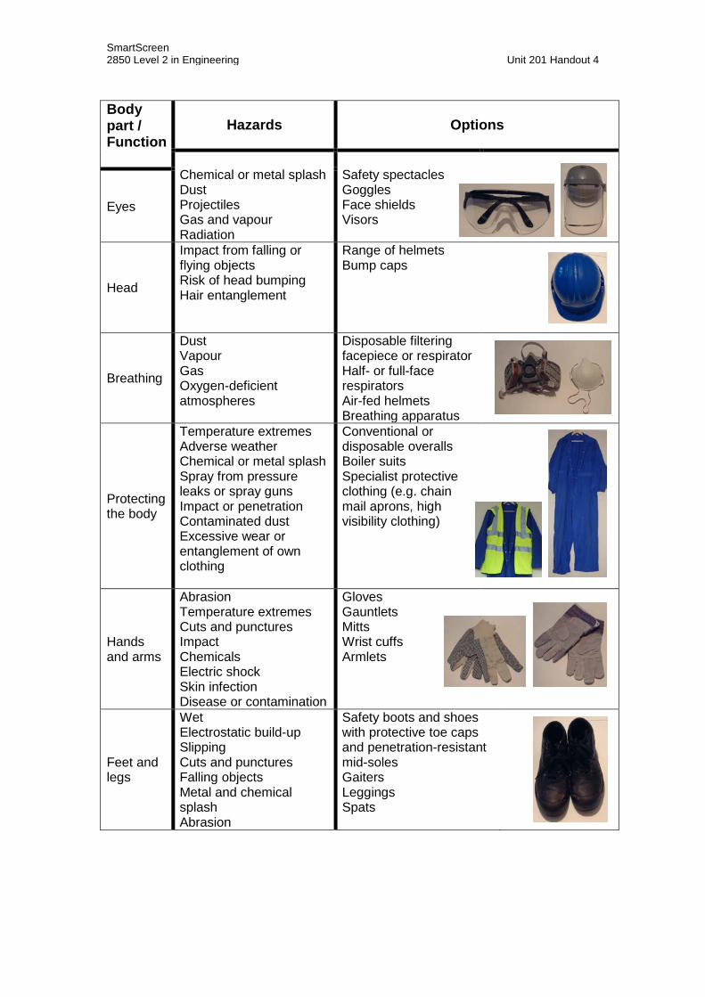
Body part / Function
Hazards Options
Chemical or metal splash Dust Projectiles Gas and vapour Radiation
Safety spectacles Goggles Face shields Visors
Eyes
Head
Impact from falling or flying objects Risk of head bumping Hair entanglement
Range of helmets Bump caps
Breathing
Dust Vapour Gas Oxygen-deficient atmospheres
Disposable filtering facepiece or respirator Half- or full-face respirators Air-fed helmets Breathing apparatus
Protecting the body
Temperature extremes Adverse weather Chemical or metal splash Spray from pressure leaks or spray guns Impact or penetration Contaminated dust Excessive wear or entanglement of own clothing
Conventional or disposable overalls Boiler suits Specialist protective clothing (e.g. chain mail aprons, high visibility clothing)
Hands and arms
Abrasion Temperature extremes Cuts and punctures Impact Chemicals Electric shock Skin infection Disease or contamination
Gloves Gauntlets Mitts Wrist cuffs Armlets
Feet and legs
Wet Electrostatic build-up Slipping Cuts and punctures Falling objects Metal and chemical splash Abrasion
Safety boots and shoes with protective toe caps and penetration-resistant mid-soles Gaiters Leggings Spats

SmartScreen 2850 Level 2 in Engineering Unit 201 Handout 5
Unit 201: Working in Engineering Handout 5: Safety Signs Safety signs The colour schemes used for UK road and safety signs are similar. The colours red, yellow, green are associated with traffic lights and respectively mean stop, caution (danger) and go. The meaning of these three colours can be transferred to safety signs.
STOP – prohibition signs Meaning:
• you must not • do not • stop.
DANGER – warning signs Meaning: • caution • risk or danger • hazard ahead.
SAFETY – safe condition and first aid signs Meaning: • the safe way • first aid equipment • where to go in an emergency.
OBEY – mandatory signs Meaning: • you must • carry out the action shown.
FIRE – fire signs Meaning: • location of fire fighting equipment • type of fire fighting equipment.

SmartScreen 2850 Level 2 in Engineering Unit 201 Handout 6
Unit 201: Working in Engineering Handout 6: Roles, Responsibilities and Powers For an engineering workplace to be a safe and healthy place to work, a number of individuals need to take responsibility for the implementation of good work practices. Safety officers
• Work on behalf of an employer to implement and improve the company’s health and safety policy.
• Members of a safety committee. Safety representatives
• Trade union officials who work on behalf of the workforce to ensure that the workplace is a safe and healthy place to work.
• Members of a safety committee. Health and safety executive (HSE) inspectors Have statutory powers under the Health and Safety at Work Act to observe work done in a workplace. If they decide that the premises, equipment or work practices are unsafe, they can issue two types of notice which must be followed:
• Improvement notice – the company/employer must rectify the problem but can appeal against the notice
• Prohibition notice – the company/employer must change the way of working immediately.
SmartScreen 2850 Level 2 in Engineering Unit 201 Handout 7
Unit 201: Working in engineering Handout 7: Causes of Accidents and Accident Prevention
Causes of accidents
Accidents can be caused by a number of means, many by human error:
• Tiredness – accidents can happen if a worker is tired and/or it is approachingthe end of a long work period. A mistake is made resulting in an accident/personal injury.
• Hunger – when someone is hungry their level of concentration can drop; amomentary lapse can result in an accident.
• Time of day – for the two reasons given above accidents are more likely inthe time close to the lunch break.
• Inappropriate behaviour – many engineering workplaces such asworkshops and factories are potentially more dangerous than many other work locations such as offices. Inappropriate behaviour in an engineering environment is therefore more likely to result in an accident.
• Dress (clothing, jewellery, hair) – loose clothing, dangling jewellery, a tie orlong hair can easily become trapped in rotating machinery, dragging the person into the machine.
• Lack of training/experience – it is important to avoid accidents by makingsure that you have received the right training and experience to carry out a work activity. Being a competent person is a good safety measure to reduce the risk of experiencing an accident at work.
• Repetitive/boring activities – some tasks in engineering can be veryrepetitive and inherently boring; a lapse in concentration can result in an accident.
• Blunt/broken/inappropriate tools – using a blunt cutting blade needs morepressure to be applied; it is therefore easier to slip and cause an accident. A broken hand tool can easily cause a hand injury. Using the right tool for the right task is a good way of avoiding an accident.
• Overriding safety guards – a finger or hand can easily be severed by ametal press if hand guards are removed or overridden.
• Poor ventilation – many engineering activities (e.g. welding) generate fumesthat can be harmful to health. A lack of oxygen can result in an individual feeling light headed and collapsing – an accident waiting to happen.
• Dirty and untidy work areas – waste materials and liquids on a workshopfloor increase the risk of accidents.
• Overcrowded – too many people working in a limited space can increase thechances of an accident happening. Blocked walkways/exits can be dangerous if there is a need to evacuate a building due to an emergency, such as the breakout of fire.
• Poor lighting – a well-lit workbench/workplace is a safe workplace. Poorlighting can result in trips and falls in walkways. A flickering light can have a strobing effect on a rotating machine – a dangerous combination.

SmartScreen 2850 Level 2 in Engineering Unit 201 Handout 7
Accident prevention
The risk of an accident can be reduced by a number of means:
• Eliminating the hazard – this is obviously the ideal way to stop accidentshappening.
• Reducing the hazard – elimination is not always possible so the next bestchoice is to reduce the hazard. Accidents are therefore less likely to occur.
• Guarding the hazard – barriers, enclosures and guards can be used to makepeople aware of a hazard. Similarly a section of the workplace can be set aside for use by specially trained/competent people. Machinery can be designed to only operate when guards are in place to stop accidents occurring.
• Personal protection – the wearing of personal protective equipment (PPE)and respiratory protection equipment (RPE) can eliminate accidents by stopping dangerous chemicals, extremes of temperature, abrasive material, etc coming into contact with the skin.
• Safety education and publicity – good safety training can make recentlyrecruited employees aware of the hazards associated with their new jobs. Expected codes of conduct can be instilled into new staff. Publicity, such as safety posters, can act as positive/timely reminders of the need to maintain high safety standards at all times in the workplace.

SmartScreen 2850 Level 2 in Engineering Unit 201 Handout 8
Unit 201: Working in Engineering Handout 8: Risk Assessment
Hazard A hazard means anything that can cause harm eg chemicals, hot surfaces, rotating machinery, asbestos, electricity, working from ladders or scaffolding.
Risk A risk is the chance – high or low – that somebody will be harmed by the hazard.
Assessing risks in the workplace
There are five steps to risk assessment:
STEP 1: Look for the hazard.
STEP 2: Decide who might be harmed and how.
STEP 3: Evaluate the risks and decide whether the existing precautions are adequate or whether more should be done.
STEP 4: Record your findings.
STEP 5: Review your assessment and revise it, if necessary.
Typical risks found in an engineering workplace
• Slippery or uneven floors • Spillages (e.g. coolant, lubricants)
• Scrap or waste material • Faulty or missing machine guards
• Inflammable materials • Faulty electrical connections or damagedcables
• Dust or fumes • Materials handling and transportation
• Contaminants or irritants • Defective/poor lighting
• Visitors • Untrained/new members of staff
• Rotating machinery • Elevated levels of noise
• Vibration • Heavy objects/tools

SmartScreen 2850 Level 2 in Engineering Unit 201 Handout 9
Unit 201: Working in Engineering Handout 9: Rules for Observance of Safe Practices, First Aid and Dangerous Occurrence
Rules for the observation of safe practices There are five simple rules for the observance of safe practices:
1. Be alert – use your natural senses (sight, smell, hearing and, with caution,touch) to be aware of hazards.
2. Maintain personal hygiene – change/clean your PPE at regular intervals.Disposable items such as dust masks need to be changed at the correct time interval. Do not share your PPE, such as footwear and ear protectors, with others.
3. Protect yourself and others – you may be responsible for others due to theirlack of experience so it is important that you protect yourself and others. Having a positive attitude is one of the best tools you can use for adopting safe systems of working – be prepared to change and to take on new work practices to improve levels of safety.
4. Know emergency procedures – practising safety procedures such as fireescape is an important precautionary activity – it may be for real one day. Knowing escape paths and keeping escape routes clear is an important safety measure in an engineering workplace. Knowing how to use an emergency eye washing station could save a colleague’s sight. Knowing how to administer first aid could be a life saver! Know where to assemble when there is an emergency.
5. Report all hazards – safety officers and safety representatives should beworking together to ensure that their common workplace is a safe and healthy place to work. If you see a hazard, report it so that it can be dealt with before someone gets hurt.
First-aid treatment The location of first aid facilities is identified by special safety signs. Similarly, safety signs advise where first aiders can be found and their contact details (telephone numbers, radio call sign, etc). In a large workplace there may be full-time first aiders. For smaller workplaces, first aiders are part of the normal workforce. Learning first aid is worthwhile as such knowledge/skills can be used at home, at work or outside in the street or sports ground.
Dangerous occurrence A dangerous occurrence is a ‘near miss’, which could have led to serious injury or loss of life. Dangerous occurrences are defined in the Reporting of Injuries, Diseases and Dangerous Occurrences Regulations (RIDDOR) 1995 and are reportable to the Enforcement Authorities.

SmartScreen 2850 Level 2 in Engineering Unit 201 Handout 10
Unit 201: Working in Engineering Handout 10: Fire, Fire Prevention, Fire Drills and Fire Equipment
What is a fire?
In simple terms, fire is very rapid oxidation. Rusting iron is an example of slow oxidation. Fire, or combustion, is rapid oxidation as the burning substance combines with oxygen at a very high rate. Energy is given off in the form of heat and light. Because this energy production is so rapid, we can feel the heat and see the light as flames.
For an outbreak of fire there must be the following three elements present:
• FUEL – anything that can burn
• HEAT – the temperature at which fuel ignites (the flash point)varies from one fuel to another
• OXYGEN – present in air (21%).
Take away any one of these and the fire stops.
Fire prevention
Preventing fire depends on:
• highly flammable elements being identified• keeping the three elements that make up a fire apart• following specific procedures to control the elements when they cannot be
separated or are required for a particular job.
Recognising flammable material – warning signs are used to indicate that a material is flammable and dangerous to use. Colour coded pipes identify what type of gas or chemical is being used. Different fittings and threads on pipework can prevent the wrong gases being connected.
Storing flammable material – make sure flammable material does not come into contact with other flammable material – heat or oxygen. There are strict regulations that prescribe how gas cylinders must be stored. In a fire, gas cylinders are potentially a high risk source of an explosion. Exclusion zones are established for many hours to allow gas cylinders to cool after a fire has been extinguished.
A fire in a workplace can result in the business closing down and all jobs being lost. The time taken to re-establish an engineering business is far greater than an office-based business using IT equipment. Common causes of fires in industrial premises are electrical faults and sparks from engineering processes, such as welding and grinding. A spark can fly away from a workpiece and smoulder for a long period of time before flames are visible. Checking a workplace at the end of a working day/shift for signs of fire is good work practice. It ensures you will have a job/workplace the next day.

SmartScreen 2850 Level 2 in Engineering Unit 201 Handout 10
Fire drills
Fire drills are an important activity to show readiness for the day a real fire may occur. It may be a nuisance going outside on a cold and wet day to assemble in the car park and have your name called to make sure you are safe – but it may be for real for one day!
Fire drills need to be tested at regular intervals. Normal work areas should have fire drills twice per year. In engineering workplaces, where there are hazardous processes, fire drills need to be more frequent. Many engineering processes, such as steel furnaces, are continuous (all day and all night) and cannot be stopped. Therefore work is carried out in shifts and fire drills must be planned so that all workers (part-time, full-time and shift) practice the emergency evacuation process/fire drill.
Emergency exits need to be clearly identifiable, even if the building’s power supply fails. Access to emergency escape paths/exits needs to be unobstructed. Emergency exits must not be locked when a building is occupied – people must be able to get out quickly without the aid of security/caretaking staff.
Fire-fighting equipment
Fire alarm systems, fire extinguishers, fire doors/shutters and water sprinklers are all means of reducing the spread of fire and provide means of tackling fires before they get out of control.
Fire alarm A fire alarm is used to warn others that fire has been discovered. Strategically placed smoke detectors can automatically set off a fire alarm system when smoke is detected. When the alarm sounds certain staff have set responsibilities to carry out set tasks, if safe to do so, to make sure everyone has left the building; to call the fire brigade; to administer first aid to colleagues if required.
Water sprinklers Water sprinklers provide a means for water to be sprayed over a floor area quickly to extinguish a fire before it gets out of control. They can be designed to activate automatically in a localised area having been set off by the heat of the fire.
Fire doors/shutters Fire doors and shutters are designed to provide a fire break for a set period of time dependent on the location. They can be made to close automatically when a fire alarm system has been set off. Fire doors and shutters can be used to create a safe refuge for people trapped before fire fighters arrive on site.

SmartScreen 2850 Level 2 in Engineering Unit 201 Handout 10 Fire extinguishers Fire extinguishers can be used to put out a small fire before it gets out of control. There are a range of extinguishers for use on different types of fires. It is important to use the right type of extinguisher on the right type of fire. It is important to be trained in how to use fire extinguishers correctly. Do not put yourself or others at risk by staying in a building fighting a fire for too long before evacuating the premises. Get out and stay out – leave it to the professional fire-fighters!
Water Colour Red Intended use
The water cools the burning material. For use on solids such as wood and paper.
Wrong use
Never use a water extinguisher on an electrical fire or burning fat or oil. Water is a conductor of electricity. Water can make an oil or fat fire worse – an explosion could occur.
How to use
Aim the water jet at the base of the flames and move it over the fire area.
Standard/multi-purpose powder Colour Blue Intended use
The powder ‘knocks down’ the flames. Safe to use on most kinds of fire. Multi-purpose powders are more effective, especially on burning solids. Standard powders work well only on burning liquids.
Wrong use
The powder does not cool the fire well. Fires that appear to be out can re-ignite. Small spaces found in mechanical/electrical equipment are difficult to fill with powder. Burning fat or oil can be spread around by the force of the jet.
How to use
Aim the jet at the base of the flames and briskly sweep it from side the side.

SmartScreen 2850 Level 2 in Engineering Unit 201 Handout 10
CO2 Colour Black Intended use
Displaces oxygen with CO2 (a non-flammable gas). Good for electrical fires as they do not leave a residue.
Wrong use
Pressurised CO2 is extremely cold – do NOT touch the horn on the extinguisher. In a confined space displacing oxygen for humans to breathe is dangerous – do not use in a confined space.
How to use
Aim the jet at the base of the flames and briskly sweep it from side the side.
Foam/AFFF (Aqueous Film Forming Foam) Colour White or cream Intended use
The foam forms a blanket or film on the surface of the burning liquid. Conventional foam works well only on some liquids, so it is not good for use at home, but AFFF is very effective on most fires except electrical and chip-pan fires.
Wrong use
‘Jet’ foam can conduct electricity back towards the extinguisher user, ‘spray’ is less likely to do this. The foam can spread burning fat or oil around.
How to use
For solids, aim the jet at the base of the flames and move it over the area of the fire. For liquids, do not aim the foam straight at the fire – aim it at a vertical surface or, if the fire is in a container, at the inside edge of the container.

SmartScreen 2850 Level 2 in Engineering Unit 201 Handout 11
Unit 201: Working in Engineering Handout 11: Safe Working and Safety Checks
Safe working
Before starting work on a specific task it is important to make the work area safe for those carrying out the task and those in the vicinity. In a workplace people can be classified into one of four groups:
• Competent person – a person who possesses sufficient technicalknowledge, relevant practical skills and experience for the nature of the work undertaken and is able at all times to prevent danger, and where appropriate, injury, to him/herself and others.
• Skilled person – a person with technical knowledge or sufficientexperience to enable him/her to avoid dangers which the work activity may create.
• Instructed person – a person adequately supervised by skilled personsto enable him/her to avoid dangers which the work activity may create.
• Ordinary person – a person who is neither a skilled person nor aninstructed person.
The methods and procedures in making a work area safe depend on whether competent, skilled, instructed or ordinary persons are involved.
Barriers and tapes
Barriers and tapes do not offer a high level of protection in securing a work area. They can be easily got around. They are therefore only appropriate for use by competent, skilled and instructed persons
Warning signs
Warning signs can be used to make individuals aware of hazards or to give instructions to them. A warning sign can be ignored – either missed accidentally or intentionally by an individual intent on inappropriate behaviour. A warning sign on its own is not sufficient in many circumstances.
Informing people who may be affected by the work
Some work may mean that there will be a temporary interruption to a supply of water, electricity, gas or air line. It is important to inform those who may be affected for the following reasons:
• Courtesy – customers can be both internal and external to anorganisation. Customer care skills are an important part of the tool kit of a good engineering maintenance technician. Information is important to people when there is a disruption to normal circumstances.
• Avoiding damage – the sudden disruption of a service could causedamage to equipment because a vital energy source has been lost.

SmartScreen 2850 Level 2 in Engineering Unit 201 Handout 11
• Threat to life – a hospital is a sophisticated building with many vitalbuilding services. Important engineering functions contribute to the well-being of the patients. Liaison with medical staff is therefore critical when work is going to be carried out.
Isolating power or pressure sources
Isolating and locking off power and pressure sources are extremely important safety procedures. The locking off process with a padlock ensures that the supply cannot be restored without the keyholder’s knowledge. It can be arranged so that several padlocks can be used to lock off a supply. Every person working on the secured supply has a unique key to his/her padlock kept with him/her whilst working. When everyone has stopped work all of the padlocks have to be removed before the supply can be reconnected.
Permit to work
Safe systems of work are crucial in work such as the maintenance of an engineering plant where the potential risks are high and the careful coordination of activities and precautions is essential to safe working. In this situation and others of similar risk potential, the safe system of work is likely to take the form of a permit to work procedure. In London, an example of a location where permits to work would be used is the Underground rail system. During the night and at weekends, engineering work is carried out to maintain or renew the railway network. The electrical supply used by the trains during the day has to be switched off before work crews enter the tunnels. A permit to work system is used to ensure worker safety. In the early hours of the morning the electrical supply has to be restored ready for the commuter rush hour. The lines must be cleared of workers, tools and materials before this is done – the permit to work system ensure this happens safely and in a timely manner.
A permit to work document will typically specify:
• what work is to be done• the plant/equipment involved, and how they are identified• who is authorised to do the work• the steps which have already been taken to make the plant safe• potential hazards which remain, or which may arise as the work proceeds• the precautions to be taken against these hazards• for how long the permit is valid• that the equipment is released to those who are to carry out the work.
Signatures of the individuals responsible for the work are also required on the permit to work. In the case of an accident, such signatures create an audit trail that an HSE safety inspector could review to find out who failed to observe safe working procedures and contributed to the cause of the accident being investigated.

SmartScreen 2850 Level 2 in Engineering Unit 201 Handout 11
There are three types of permit to work:
1. General
2. Confined space (chambers, tanks, vessels, furnaces, ducts, sewers,manholes, pits, flues, excavations, boilers, reactors and ovens)
3. Hot work (cutting, welding, brazing, soldering and any process with a nakedflame).
Safety checks
Safety checks are important for the following reasons:
• to maintain or improve safety standards• to ensure that work areas are free from hazards• to confirm that safety procedures are being implemented• to check that PPE (personal protective equipment) is in a usable condition
and appropriate for the task • tools and equipment need to be checked to ensure they are in a safe and
usable condition.
Safety checks need to be carried out at regular intervals. Safety officers and safety representatives need to implement safety checks together working to maintain/improve the workplace as a safe and health place to work.

SmartScreen 2850 Level 2 in Engineering Unit 201 Handout 12
Unit 201: Working in Engineering Handout 12: Employment Rights
Employment rights
At work we have rights and with these rights there comes responsibilities. Being absent from your workplace may be for one of the following reasons.
Illness – medical/dental reasons
Illness can affect anyone unexpectedly. Workers who are not fit for work need to be signed off by a doctor; similarly before returning to work, a doctor needs to check to ensure fitness for work. Working whilst unfit for work could cause a serious safety hazard. Some medications can cause drowsiness which can be extremely dangerous if working with machinery.
Dependent on conditions of employment you may be entitled to sick pay. A period of long-term sickness may see a reduced level of pay after a certain period, for example six months. Self-employed workers typically do not receive any sick pay.
Holidays
Holidays from work take the form of annual leave and public holidays. The timing of annual leave has to fit in with work activities. In some production companies there is an annual shutdown when production staff are on leave. The time of year may mean that the Christmas/New Year break is extended due to adverse weather conditions/lack of natural daylight. The amount of annual leave entitlement often increases with the length of service with an employer. Self-employed workers typically do not receive any holiday pay.
Family reasons
It may be necessary to take time off work due to family reasons (bereavement, childcare, maternity/paternity leave). This leave may be paid or unpaid dependent on the terms and conditions of your employment.

SmartScreen 2850 Level 2 in Engineering Unit 201 Handout 13
Unit 201: Working in Engineering Handout 13: Communication Systems Used in the Workplace
Effective communication is important to any successful business and a variety of communication methods can be used in a workplace. For engineering, the use of visual/graphical communication in the form of drawings/diagrams is more common; ‘a picture is worth a thousand words’.
Types of communication
Verbal • Quick and easy to give• Dynamic – real time• Used for informal discussions either face to face or on the
telephone • Can be used to present the same information to a group of
employees in the form of a briefing/presentation. But:
• Has no record• May be misunderstood• May be forgotten• May be denied.
Written • More reliable than verbal communication• Takes time to prepare• Can be used to create a positive image of company to its
customers. But:
• Has limited shelf life – may go out of date or be invalid with time• Needs to be controlled to ensure currency/accuracy.
Drawings • An important means of communication for engineers and
technicians • An agreed set of symbols and conventions can be used to
represent complex systems • No language barrier if internationally agreed symbols are used• Simplifies written (text-based) communication• Can aid the understanding of a written explanation of how a
complex device is assembled on a production line or dismantled for maintenance purposes.

SmartScreen 2850 Level 2 in Engineering Unit 201 Handout 13 Electronic
• Electronic documents are easily stored • For security, off-site back-up can aid the recovery of a business
following a disaster such as a flood or fire • Electronic (word-processed) documents can be readily modified. • With the use of email, documents can easily be distributed as
attachments to a wide global audience • Instant communication – email/electronic documents can be used
to overcome time differences around the globe for international businesses
• Computer software packages (CAD) can be used to develop drawings
• Three-dimensional software can be used to animate an object. It is possible to ‘walk-through’ a planned building before it is built.
Signs
• Can be designed to follow a colour code that implies the status of the information presented by a sign, (e.g. road and safety signs use the colours red, yellow, green and blue)
• The shape of a sign can be designed to imply the status of the information presented (e.g. a triangular road sign implies a warning)
• Symbols can used to provide highly effective visual instructions • Can be used to advertise/project a positive image of a business • Company logos can be used on signs to project a strong branding.
But: • Need to be concise and to the point – not too many words.

SmartScreen 2850 Level 2 in Engineering Unit 201 Handout 14
Unit 201: Working in Engineering Handout 14: Roles and Responsibilities within an Engineering Organisation Roles and responsibilities within an engineering organisation A typical engineering organisation is made up of a number of departments working together to keep the business profitable. Finance/Purchasing Any business without a finance/purchasing function is unlikely to trade for any length of time before running into financial difficulties. The finance department is responsible for:
• making sure that a profit is made when the products manufactured by an engineering firm are sold.
• managing the company payroll • invoicing customers for goods and services supplied.
Purchasing is concerned with the sourcing of raw materials for turning into finished goods that are sold on to customers. If there is a rise in the cost of raw materials, there are two means of coping with this rise in overheads: there either needs to be a rise in the price charged to customers or the cost needs to be absorbed by the organisation by, for example, changing work methods or the design of the product Manufacturing/Production Manufacturing/production is one of the most important parts of an engineering business. Its primary function is to turn raw materials into finished goods. The materials that arrive at the start of the production line can be basic/raw materials such as metal rods/bars, sheet metal and plastic pellets. Some production lines can be supplied with sub-assemblies such as nuts and bolts, electronic components and printed circuit boards, and plastic mouldings produced by another production line. Production/manufacturing activities need to be organised to match customer orders. Quality assurance/control The production of quality products is essential for customer satisfaction and the generation of goodwill for a business. Quality checks can be applied at the various stages on a production line. Raw materials can be checked before they are used; this can save time and money by not using defective materials. Finished goods can be checked before they are despatched to customers. Quality systems needs to be cost effective and appropriate for the goods involved. Taking a sample from a batch can provide an indication of the overall quality. The

SmartScreen 2850 Level 2 in Engineering Unit 201 Handout 14 size of the sample needs to be appropriate; as the size of the sample is increased, the cost of operating the quality system increases. For some safety critical engineering goods, every item needs checking – a good example would be aircraft components. Inspection Inspection is essentially part of a quality assurance system. It is essentially a visual process. For some engineering components it may be necessary to use camera systems to inspect the inside of manufactured goods. X-ray photograph can be used to ensure welded joints are sound and will not fail under load. Despatch Finished goods need to be packed so that damage is not experienced in transit to the customer. Appropriate packaging needs to be designed to suit the means of transport used (road, air or sea). The despatch department is responsible for assembling customer orders as set out in delivery notes. Maintenance To keep a production line operational and a safe place for people to work requires a programme of maintenance. Maintenance can be described as reactive when it is in response to a production line that has stopped due to the failure of a constituent part. Planned/preventative maintenance is described as pro-active and can lead to less failures in a production line due to defective plant. Some maintenance has to be carried out on a production line that has been stopped due to safety reasons. The timing of maintenance activities needs to be planned for when a line is closed for other reasons such as staff all being on holiday at the same time or when demand for goods has a seasonally low period. Human resources This department is responsible for:
• recruiting staff to keep a business viable • inducting new members of staff • arranging training and professional development of staff • monitoring annual and sick leave • developing company policies and procedures.

SmartScreen 2850 Level 2 in Engineering Unit 201 Handout 14
Personnel
In an engineering workplace there is a wide range of employees with different roles and skills:
• Managers – responsible for the running of the organisation atvarious levels. The directors of a business are the highest level managers and are most likely to own the business.
• Engineers – most likely to be qualified to degree level andmembers of the professional body for their area of engineering. Take professional responsibility for work to be safe and fit for purpose.
• Supervisors – responsible for the work of others, organisingteams. Have most likely gained previous experience of the tasks they are supervising.
• Trainers – responsible for enabling staff with new skills. May befrom an outside organisation depending on the content/level of training involved.
• Inspectors – responsible for ensuring the quality of raw materialsand finished goods. In some cases they may carry out investigations and write reports.
• Safety officers – responsible for implementing and improving anorganisation’s health and safety practices.
• Personnel staff – responsible for keeping personnel records andmonitoring attendance/punctuality. Responsible for the welfare of the workforce.
Trade unions
Trade unions play an important role in representing workers in the following ways when at work. They:
• negotiate pay and conditions of service with an employer• provide support in cases of disciplinary action• provide safety representatives• act on safety issues reported anonymously• financially support political parties – typically New Labour• provide training for union representatives.

SmartScreen 2850 Level 2 in Engineering Unit 201 Handout 15
Unit 201: Working in Engineering Handout 15: Instructions, Requests and Advice, and Sources of Engineering Information Instructions, requests and advice An instruction must be followed. It may be that failure to follow an instruction could result in an unsafe situation being created. In some organisations the failure to follow an instruction could result in disciplinary action being taken against an employee. A request is not as authoritative as an instruction. There are not necessarily any unpleasant consequences for not carrying out a request. A request is something that someone would like you to do. Advice is information that can taken by an individual and, following some time to think and reflect on it, may be acted upon. Sources of engineering information Information is an essential ingredient in an engineering environment. There are many sources of information available. BS EN Standards Published standards (BS and EN – UK and European) can be used for a variety of reasons in an engineering workplace:
• to show compliance with safety law such as the Health and Safety at Work Act
• to prove that manufactured goods have been produced to a known standard
• to save money by not having to carry out further testing • to prove that manufactured goods are safe • international standards make goods easier to export to other countries • to provide codes of good practice.
Instruction manuals Instruction manuals are designed to tell the reader how to use a particular item of equipment. It may include instructions on how to assemble the product for use. The instructions are normally presented in a logical sequence and designed for use by non-technical people. Advice on how to sort out simple problems may be included.

SmartScreen 2850 Level 2 in Engineering Unit 201 Handout 15 Technical handbooks Technical handbooks are much more detailed than instruction manuals and are designated for use by experts. The contents of a technical manual typically includes:
• parts lists • exploded view/assembly diagrams • recommended maintenance schedules • detailed explanations of how the equipment works • circuit diagrams • wiring diagrams • block diagrams • flow diagrams • testing methods/schedules.
Tables, charts, graphs and data sheets Tables, charts, graphs and data sheets are all means of providing graphical information; ‘a picture is worth a thousand words’. Textbooks and reference manuals Textbooks and reference manuals can be sources of technical information. Textbooks take time to go to press. In areas of work that are experiencing rapid developments in technology, textbooks are not produced quickly enough - technical journals/manuals are more appropriate. Computer programmes, the internet and intranets Computer programmes, the internet and intranets can provide sources of information that can be readily updated and accessed from any global location. Computer programmes can be used to aid design and to carry complex calculations. An intranet is a closed access computer network used to store/access information owned by an organisation. The internet is open to all users on a global basis.
SmartScreen 2850 Level 2 in Engineering Unit 201 Handout 16
Unit 201: Working in Engineering Handout 16: Methods of Communicating Technical Information Technical information can be communicated in a number of ways:
• Sketches, drawings and diagrams – sketches can be produced by hand and used for initial ideas/concepts. Drawings and diagrams are more formal and show graphical information. They are typically produced on a computer.
• Test and inspection reports – these documents can be used to log the
status of equipment in terms of safety and whether equipment is fit for purpose. The outcome of test measurements can be recorded for reference later to identify trends in data. A component may be identified as beginning to fail.
• Planning documents and schedules – these can be vitally important to
make an engineering organisation profitable and in meeting the needs of its customers in a timely manner. Techniques such as critical path analysis can be used in such documents.

SmartScreen 2850 Level 2 in Engineering Unit 201 Handout 17
Unit 201: Working in Engineering Handout 17: Design Brief, Sources of Guidance and Behaviour
Design brief
A design brief specifies the requirements for a design. It is given to a designer or a team of designers to tell them what is required. A design brief may result from discussions with a customer who wishes to commission a new product. Market research may be used to show demand for a new product. Design briefs can vary considerably in both form or content. An existing product may need improvement so a design brief would be written in order to specify how the product needs to be modified. A design brief could include the desire to reduce manufacturing costs due to competitors having a cheaper rival available. Poor reliability could trigger a design brief to improve a products reputation. The need for an existing product to comply with new legislation would mean a design brief is needed.
A typical design brief would involve consideration of:
• ergonomics • technical specification• quality • maintenance• cost • application/function• aesthetics • size• legalisation • scale of production• weight • materials.
Mentor, trainers and supervisors
In a typical workplace advice and guidance can be obtained from a variety of sources:
• Mentors are colleagues who act as guides or advisors. Their advice is based ontheir previous experience at work in a similar role to yours.
• Trainers are responsible for helping workers learn new skills or gain newknowledge. They may be colleagues or from another organisation dependent on what is being taught.
• Supervisors are first line managers to whom you are accountable for your workand conduct. They are responsible for you especially in terms of your well-being regarding health and safety.
Behaviour
When seeking advice it is important to be polite and courteous. Asking questions is important to show that you paying attention to what is being said to you.

SmartScreen 2850 Level 2 in Engineering Unit 201 Handout 18
Unit 201: Working in Engineering Handout 18: Technical Drawings and Specifications Graphical information is a very important element of communication for those who work in engineering. Technical drawings and specifications can be used show the characteristics of a product in terms of:
• shape – this is important in terms of its appearance (aesthetics) being pleasing to the eye. The shape of an object can contribute to its aerodynamics/wind resistance
• size – this is important in terms of how much material is required. The
use of scale is obviously important on using a drawing to derive actual dimensions
• material – this has implications in terms of weight and cost
• features – what a product can do.
Technical drawings can be used to give additional product information:
• Materials – the type and quantity of materials required.
• Manufacturing or installation data – details of any specialist jigs or templates that make manufacture or installation easier and more reliable.
• Special processes/equipment requirements – details of specialist
processes or equipment is listed to avoid wastage of materials or damage to manufacturing tools and equipment.

SmartScreen 2850 Level 2 in Engineering Unit 201 Handout 19
Unit 201: Working in Engineering Handout 19: Technical Drawings Using Current Standards Projections Orthographic projection is a drawing system that sets out two or more views of components for manufacture on paper in a logical manner. This is the preferred method of drawing components for manufacture. There are two variants – first angle projection and third angle projection.
In first angle projection the views are laid out on the opposite side as they are viewed from.
In third angle projection the views are laid out on the same side as they are viewed from. Isometric projection is used when a pictorial shape of the finished object is required and shows a 3D-like image . It is used extensively in books and catalogues because it is easy to visualise, especially for non-technical people. On isometric drawings, all horizontal lines on the X and Y planes are drawn at 300 and vertical lines are drawn vertically. All lines are drawn to a constant scale. Oblique projection is used when a component’s shape is dominated by curves and circles that make it difficult to draw the isometric projection. On a oblique projection drawing, the main front is drawn full size and true shape. The remaining faces are then filled in, receding at an angle of usually 450.

SmartScreen 2850 Level 2 in Engineering Unit 201 Handout 19
Drawings
General arrangement (GA) drawings show all the component parts correctly assembled. For parts that are manufactured in the same workplace, the relevant detail drawing number will be included. For parts that are sourced from outside, the maker and catalogue number will be listed on the GA drawing. A general arrangement drawing can be described as a signpost to other drawings or sources of supply; it does not normally carry detailed dimensions. Overall dimensions may be provided for reference purposes only.
Service manuals for engineering plant and machinery use exploded (assembly) drawings to show the component parts in the correct relationship to each other. Part numbers are included to assist in the process of ordering spare parts.
A schematic diagram represents the parts of a system using abstract graphic symbols rather than realistic pictures. For example, in electrical/electronic engineering, a wiring diagram does not bear any physical resemblance to the equipment that has to be interconnected – it identifies the terminals of the devices to be interconnected and lines drawn between the devices represent the wires making the circuit operational. A complex chemical plant consisting of vessels, piping, valves, pumps and other equipment can be represented by a simple schematic diagram to show the chemical process involved, with symbols representing all of the complexities of the plant.
In everyday life a common example of a schematic drawing would be a diagram showing the stations on a railway system such as the London Underground. There is no mention of scale, with the symbolic elements arranged to be more easily interpreted by the viewer. A well-designed schematic diagram gives the user all the information he/she needs whilst avoiding unnecessary visual clutter – the map of the London Underground is an example of an awarding winning iconic schematic drawing.
Sketches are basically freehand drawings that lack accuracy but are a quick and therefore useful means of communicating and can be used in a number of contexts:
• A creative product designer wants to capture a new idea or conceptbefore he/she forgets it.
• A trainer needs to explain how a piece of machinery works to a newapprentice.
• A visitor needs to know how to find a location within a large engineeringcomplex.
• Explaining how an accident occurred.• To record/capture the outcome of a design team meeting.

SmartScreen 2850 Level 2 in Engineering Unit 201 Handout 20
Unit 201: Working in Engineering Handout 20: Essential Information found on Technical Drawings The information presented on technical drawings must be complete for them to be used and/or interpreted correctly. The absence of critical information can make a drawing unusable; listed below are examples of essential information found on technical drawings: The projection used on a particular drawing is a critical factor for the viewer of a diagram to visualise the object shown correctly. The scale of a drawing is important to be able to judge relative size. A scaled drawing can be used to order the correct amount of raw materials to build an object shown in a scaled drawing. Dimensions are similar to scale in terms of interpretation when shown on a technical drawing. The control/validation of a drawing is important – are you looking at the latest drawing? To document the changes made to a technical drawing, a system of issue numbers is used to show the status of a particular drawing. Old drawings need to be archived to avoid time, materials and money being wasted on the wrong issue of a drawing. Every time a modification is made to a drawing, the issue number is incremented by one. A table shown on a drawing will record the dates of when and reasons why it was modified. Recording the name of the person who originated a drawing is important in order to be go back and ask why it has certain details/aspects. The author of a drawing needs to be recorded to give credit to that individual. In the case of an accident that has been caused by failure of an engineering component the designer/author of the drawing needs to be known. Engineering tolerance is the permissible limit of variation in a physical dimension. Tolerance is shown on technical drawings to show the difference between the upper and lower limits of the dimensions (limits of size) to which components need to be made. Typically a smaller tolerance means that the cost of manufacture is higher.

SmartScreen 2850 Level 2 in Engineering Unit 201 Handout 20
Abstract graphic symbols are used on schematic drawings to represent parts of a system rather than using realistic pictures. The meaning/interpretation of symbols needs to be to an agreed code or standard (UK, European or international, eg BS 8888, BS 1553, BS 3939 and ISO 22553).
Tool/equipment references may be shown on an engineering drawing to highlight the need for special jigs, fixtures, tools and cutters. Their physical location in the workshop store may be recorded to aid locating items that are not used very often.
Warning notes can give important advice that may relate to topics such as safety or avoiding damage to tools or materials.
There is a need for product specification on a drawing in order to define what the product is capable of.
Detailed drawing design may be required for component parts that are complex, small in size or intricate.
Materials needs to be listed on a drawing in order to meet the product specification. Incorrect materials could lead to a component failing and causing injury.
Batch requirements on a drawing may state the minimum number of items that must be made to make it economic to produce. Bespoke/one-off production is much more expensive than mass production.
Parts lists on a drawing make easy to order spare parts for maintenance purposes.
Performance details on a drawing give an indication as to the capability of product.

SmartScreen 2850 Level 2 in Engineering Unit 201 Handout 21
Unit 201: Working in Engineering Handout 21: Purposes of Engineering Standards, Manufacturers’ Tables, Graphs and Specifications and Conventions on Drawings Engineering standards Parts made by two different companies are interchangeable if they are manufactured to the same engineering standard. The interchange of parts gives the consumer greater confidence in security of supply and price competition between suppliers. International standards can break down trade barriers between countries. Various national standards organisations have worked together for many years to harmonise international standards:
• UK – BSI (British Standards Institute) • Germany – DIN (Deutsches Institut für Normung)
• USA – ANSI (American National Standards Institute). The International Standards Organisation (ISO) is responsible for international standards. The existence/use of a standard can improve/speed communication between manufacturers and their customers. Mass production is much easier when working to a published standard. Testing and inspection of goods for the purposes of quality is very difficult if a known/agreed standard is not used. A reference, ‘pass mark’ or standard is needed to be able say that tested items are fit for purpose. A standard can have a wide range of functions. It can:
• define physical dimensions of items such as nuts and bolts
• define the composition of materials eg steel – BS 970
• provide details of a destructive testing process to prove a defined level of safety for a product, eg crash testing cars
• provide a code of good practice in order to meet a statutory requirement for a prescribed level of safety, eg BS 7671: 2008 IEE 17th Edition Wiring Regulations
• define abstract safety signs in terms of colour scheme and interpretation/meaning
• define abstract symbols when used on schematic drawings in terms of interpretation/meaning
• describe practices, eg BS 308 – engineering drawing practice
• specify colour codes for the identification of raw materials, eg tubes and tubing BS 5383.
Tables, graphs and specifications In order to assist their customers in the selection of raw materials and sub-assemblies, manufacturers provide tables, graphs and specifications that describe their products. These documents typically carry the following information:
• Material type and section – composition of materials and shape

SmartScreen 2850 Level 2 in Engineering Unit 201 Handout 21
• Tooling requirements – how to cut the material
• Fastening devices – nuts, bolts, etc.
• Operating conditions – temperature, humidity, etc.
• Coding systems – letters and colours
• Safety requirements – advice on safe use/storage/disposal.
Standard conventions used on drawings Standard conventions on drawings include:
• lines – can be used on a drawing to imply visible edges, the limit of apartial view, hidden edges, centre lines and cutting planes
• shading – used to show a section
• symbols
• views – different elevations
• describes the need for an operational sheet
• detailed drawings
• manufacturing process
• product make up (number of components)
• sequence of operations
• quality control requirements
• storage and dispatch requirements.

SmartScreen 2850 Level 2 in Engineering Unit 201 Handout 22
Unit 201: Working in Engineering Handout 22: Expected Behaviour and Conduct Expected behaviour As an employee, you are expected to behave in the following manner: • Arriving in good time to start work at the agreed time is important to keep your
employer happy. If you are part of a team of workers, being late can mean others cannot start work without you. Unexplained absence from work is not acceptable behaviour. Continued absences and poor time-keeping can lead to termination of your employment, especially during a probation period. A poor work reference can make it difficult to find your next job.
• A typical engineering workplace is potentially more hazardous than many other
workplaces such as offices. These risks and hazards are reduced by the observation of rules, regulations and procedures. As an employee you have a duty to follow prescribed rules, regulations and procedures – failure to do so could actually mean you are breaking the law in terms of health and safety legislation.
• Your conduct in the workplace is important in terms of what your work
colleagues think of you. The level of respect you have from colleagues will depend on your conduct.
• To make work enjoyable it is important to build good working relationships with
colleagues, supervisors and managers. Conflict is time consuming and stressful for all involved.
• Items such as tools and equipment, welfare facilities and personal protective
equipment (PPE) are provided by an employer for the benefit of his/her workers. It is important to show respect for company property. Malicious damage to safety equipment is a very serious offence and such action could endanger the lives of others.
• Safety polices and regulations must be observed at all times by all employees,
sub-contractors and visitors. Conduct • When meeting customers and visitors it is important to remember that your
conduct represents the image of your organisation. Attention to personal hygiene, dress code, tone of voice and vocabulary used are important factors when projecting a positive image of an organisation.
• When dealing with inspectors it is important to provide valid information/data in a timely manner. Internal inspectors could be involved with quality assurance processes. In the case of an accident, an external inspector (HSE) could be investigating its cause.

SmartScreen 2850 Level 2 in Engineering Unit 201 Handout 23
Unit 201: Working in Engineering Handout 23: Requesting Advice, Conflict Management, Teamwork and the Impact of Engineering on the Development of the Industrial World Requesting advice When seeking advice from colleagues, trainers or supervisors it is important to state the problem clearly and succinctly in order to save time and receive the correct guidance. Good listening skills are important when receiving verbal information. Pay attention and use your body language to show interest in the advice being given. Repeating back instructions/information confirms correct receipt. Asking questions to clarify points you have not fully understood show you have been listening but need more help in understanding more complex issues. Conflict management It is important to avoid conflict situations in the workplace by: • being polite to people – using the words ‘please’ and ‘thank you’ can have an
amazing effect on colleagues. • being aware of when it is not a good time to approach colleagues for advice –
they may be very busy and therefore under stress. If you need assistance pick a quiet period to make your request of colleagues.
• avoiding conflicts by walking away from certain situations. A raised voice is
a common sign of a person in an aggressive state –– come back when things have calmed down. Speaking quietly is an important skill to avoid conflicts arising.
• listening carefully and taking on board what is being said. This can avoid
conflicts starting-up. • following reasonable requests from supervisors without an argument
breaking out. • being a team player. This is an important attribute in the workplace – offering
help when colleagues are in need of assistance is a sign of a good team player.

SmartScreen 2850 Level 2 in Engineering Unit 201 Handout 23
Team member responsibilities
Many workplaces use teams as means of organising/motivating their employees. Team leaders are responsible for organising/running their teams; whilst team members have a part to play in working together for a common objective.
Differences of opinion will always occur between members of a team. A good team leader will listen to the different opinions and develop a solution that takes the best from both opinions. Sometimes a team leader will have to make unpopular decisions due to instructions coming from above in the organisation. A busy and profitable workplace will always have time constraints typically due to deadlines to make sure customer orders are ready on time.
An able team leader will deploy his/her team in a way that plays on the individual strengths of team members. In order to motivate team members it is important that their individual aspirations and ambitions are met – new skills need to be developed in less experienced team members. Team members must not be given tasks that are above their current skills levels – this could be dangerous to them and other members of the team. Everyone has a different personality – an experienced/able team leader will know the personalities of his/her team and use them to the overall advantage of the team.
Group discussions within a team can be used to develop solutions to problems. It is very easy to criticise other members of a team – the best form of criticism is positive which results in constructive outcomes. At times a team leader needs to be assertive, especially if the outcome of a group discussion is not popular with everyone. It may be appropriate to concede to individual or group pressure at certain times if opinions are held strongly.
The development of the industrial world and engineering
The industrial revolution was a period of time in the late 18th and early 19th centuries when major changes in agriculture, manufacturing and transportation had a profound effect on society. The development of all metal machine tools facilitated the manufacture of more production machines in other industries. A labour-based economy was replaced by one dominated by industry and the manufacture of machinery. People had to migrate to places where work became available due to these changes in technology. New skills have always had to be learnt to stay in work and provide a living for dependent family members. Every new technology has its day, being replaced by the next new technology – we live in an exciting world of changing technology.
Our modern world would be a very empty place without engineering. There would be no electricity, motor vehicles, trains and railways, roads and bridges, farm machinery or aircraft.
SmartScreen 2850 Level 2 in Engineering Unit 201 Worksheet 1
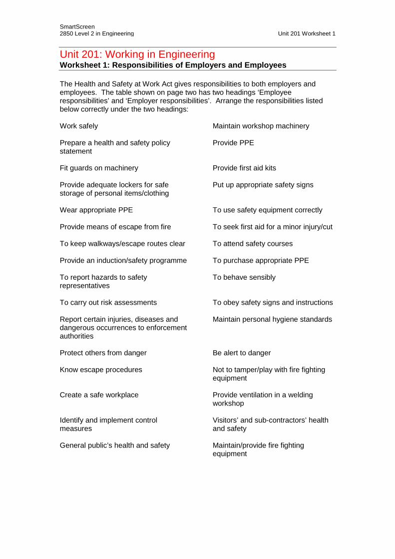
Unit 201: Working in Engineering Worksheet 1: Responsibilities of Employers and Employees
The Health and Safety at Work Act gives responsibilities to both employers and employees. The table shown on page two has two headings ‘Employee responsibilities’ and ‘Employer responsibilities’. Arrange the responsibilities listed below correctly under the two headings:
Work safely Maintain workshop machinery
Prepare a health and safety policy statement
Provide PPE
Fit guards on machinery Provide first aid kits
Provide adequate lockers for safe storage of personal items/clothing
Put up appropriate safety signs
Wear appropriate PPE To use safety equipment correctly
Provide means of escape from fire To seek first aid for a minor injury/cut
To keep walkways/escape routes clear To attend safety courses
Provide an induction/safety programme To purchase appropriate PPE
To report hazards to safety representatives
To behave sensibly
To carry out risk assessments To obey safety signs and instructions
Report certain injuries, diseases and dangerous occurrences to enforcement authorities
Maintain personal hygiene standards
Protect others from danger Be alert to danger
Know escape procedures Not to tamper/play with fire fighting equipment
Create a safe workplace Provide ventilation in a welding workshop
Identify and implement control measures
Visitors’ and sub-contractors’ health and safety
General public’s health and safety Maintain/provide fire fighting equipment

SmartScreen 2850 Level 2 in Engineering Unit 201 Worksheet 1
Employee responsibilities Employer responsibilities

SmartScreen 2850 Level 2 in Engineering Unit 201 Worksheet 2
Unit 201: Working in Engineering Worksheet 2: Personal Protective Equipment (PPE) PPE, when used correctly is designed to provide protection for different parts of the human body. The table shown on page two has seven boxes with headings that list various parts of the human anatomy. Arrange the examples of PPE listed below correctly in the seven boxes to show where the PPE is worn and/or what is designed to protect: Armlets Helmet High visibility vest/jerkin Ear plugs Gloves Leather apron Dust coat Steel capped boots Heatproof mittens Bump cap Safety shoes Dust mask Disposable coverall Back protector (when lifting) Safety spectacles Wooden clogs Thermal fleece Waterproof coat Wrist support Respirator Knee pads Spats Face mask/visor Leather gauntlet Latex/non-latex gloves Waterproof trousers/leggings Gaiters Work restraint and fall arrest kit High visibility trousers Boilersuit Knee support Safety goggles

SmartScreen 2850 Level 2 in Engineering Unit 201 Worksheet 2
Whole body
Head
Eyes
Ears
Lungs
Torso
Hands and arms
Legs
Feet

SmartScreen 2850 Level 2 in Engineering Unit 201 Worksheet 3
Unit 201: Working in Engineering Worksheet 3: Communication Systems used in the Workplace
Effective communication is important to any successful business. There are a variety of communication methods used in a workplace:
• Verbal• Written• Drawings• Electronic• Signs
The statements below each describe one of these communication methods.
Example:
No record VERBAL Its shape can be designed to imply the status of the information presented.
SIGN
Now complete the following statements:
Needs to be controlled to ensure currency/accuracy.
Dynamic – real time
An important means of communication for engineers and technicians
Instant communication – can be used to overcome time differences around the globe for international businesses.
May be forgotten More reliable than verbal communication.
Can aid the understanding of a written explanation of how a complex device is assembled on a production line or dismantled for maintenance purposes.
Symbols can be used to provide highly effective visual instructions.
Documents are easily stored. May be misunderstood.
An agreed set of symbols and conventions can be used to represent complex systems.
With the use of email, documents can easily be distributed as attachments to a wide global audience.

SmartScreen 2850 Level 2 in Engineering Unit 201 Worksheet 3
May be denied
For security off-site back-up can aid the recovery of a business following a disaster such as a flood or fire.
No language barrier if internationally agreed symbols are used.
Can be designed to follow a colour code that implies the status of the information presented
Takes time to prepare Quick and easy to give
3-dimensionalsoftware can be used to animate an object. It is possible to ‘walk-through’ a planned building before it is built.
Word-processed documents can be readily modified.
Limited shelf life – may go out of date or be invalid with time.
Simplifies written (text-based) communication.
Computer software packages (CAD) can be used to develop drawings.
Used for informal discussions either face to face or on the telephone.
Need to be concise and to the point – not too many words.
Can be used to create a positive image of company to its customers.
Can be used to present the same information to a group of employees in the form of a briefing/ presentation
Can be used to advertise/ project a positive image of a business.

SmartScreen 2850 Level 2 in Engineering Unit 201 Worksheet 4
Unit 201: Working in Engineering Worksheet 4: Essential Information Found on Technical Drawings
The information presented on technical drawings must be complete for them to be used/interpreted correctly. The table below shows information that can be found on technical drawings:
Listed below are the definitions of essential information found on technical drawings; write the correct name of the information in the right-hand box:
Example:
These abstract graphics are used on schematic drawings to represent parts of a system rather than using realistic pictures. The meaning/interpretation of abstract graphics needs to be to an agreed code or standard (UK, European or international, e.g. BS 8888, BS 1553, BS 3939 AND ISO 22553).
Symbols
Used to give sizes of drawn components.
What are these diagrams displaying?
These may be shown on an engineering drawing to highlight the need for special jigs, fixtures, tools and cutters. Their physical location in the workshop store may be recorded to aid locating items that are not used very often.
materials detailed drawing warning notes
dimensions tolerance
batch requirements symbols limits of size
author tool/equipment references issue number
projection parts lists
performance details scale

SmartScreen 2850 Level 2 in Engineering Unit 201 Worksheet 4
This a critical factor for the viewer of a diagram to visualise the object shown correctly.
Makes ordering spare parts for maintenance purposes easy.
This is required to be able to judge relative size.
This may be required for component parts that are complex, small in size or intricate.
Every time a modification is made to a drawing this is incremented by one.
Recording the name of the person who originated a drawing is important in order to be able to go back and ask why it has certain details/aspects.
In engineering this is the permissible extent of variation from a given dimension.
These need to be listed on a drawing in order to meet the product specification. If these are incorrect it could lead to a component failing and causing injury.
When shown on a drawing this states the minimum number of items that must be made to make it economic to produce.
These can give important advice that may relate to topics such as safety or avoiding damage to tools or materials.
This gives an indication as to the capability of product.

SmartScreen 2850 Level 2 in Engineering Unit 202 Handout 1
Unit 202: Principles of Engineering Technology Handout 1: Range of Materials Materials commonly used in engineering
Material grouping
Group description
Group members
Member description
Ferrous metals
Ferrous metals and alloys contain the element iron. Steels are alloys of iron and small amounts of other elements, particularly carbon and manganese.
Low, medium and high carbon steels
Versatile and widely used. Higher carbon steels are harder and can be used as cutting tools.
Stainless steel
Contains high proportion of chromium to provide corrosion resistance. Used in catering to maintain hygiene standards.
Cast iron
Contains iron and carbon. Does not need high cost refinement. Can be easily cast into complex shapes.
Non-ferrous metals
Do not contain iron. Each metal has its own properties and uses. In general, with the exception of copper, non-ferrous metals are mixed to form alloys. Many are corrosive resistant.
Aluminium and
aluminium alloys
Lightest of commonly used metals. Very good thermal and electrical conductivity. Good corrosion resistance. Mechanically weak – difficult to weld and solder.
Copper
Very good thermal and electrical conductivity. Good corrosion resistance. Easy to solder and braze. Relatively strong. Used in electrical cables.
Brass Alloy of copper (60%) and zinc (40%). Corrosion resistant. Used for plumbing fittings.
Bronze Alloy of copper (97%), zinc (2.5%) and tin (0.5%). Used for coins.
Lead
Soft, heavy, toxic and malleable. Used in batteries due to its high resistance to corrosion by acids. Poor electrical conductivity. Used in solder with tin (60% tin & 40% lead) for electrical/electronic work.

SmartScreen 2850 Level 2 in Engineering Unit 202 Handout 1
Material grouping
Group description
Group members
Member description
Non-metallic materials
Diverse in their make up. They can be plastic, organic, mineral, or synthetic materials.
Hard and soft woods
Natural material. Soft woods used for mould patterns for casting. Hardwoods used for tool handles.
Composites
Bonded components combined to gain advantages of each component’s properties. Examples: reinforced concrete, plywood, corrugated cardboard, motor vehicle belts and glass reinforced plastic.
Plastics materials
Lightweight, strong relative to weight. Good electrical insulators. Good resistance to corrosion especially acids. Two types – thermoplastics (set/reset by heating) and thermosetting (set by chemical reaction and cannot be reset).
Glass
Hard, brittle, transparent solid. Used for lenses in optical instruments and spirit level vials.
Ceramics
Very good thermal resistance. Chemically bonded metal and non-metal combination and have a very rigid structure. Used for grinding wheel grit, cutting-tool tips and high-voltage insulators.
Laminates
Constructed by uniting two or more layers of material together. The layers can be made from the same or different materials. Plywood is an example of a laminate. Vehicle windscreens use laminating to improve safety in case of an accident.
Rubber
A natural product known for its flexibility and durability. Used for belts, tyres, anti-vibration mountings and drive couplings.

SmartScreen 2850 Level 2 in Engineering Unit 202 Handout 1
Material grouping
Group description
Group members
Member description
Reinforcing materials
A combination of materials that if used on their own would fail to perform. Exploit combined strengths of composite materials.
Glass fibres
Can be used with plastics. Combined material is very strong and lightweight. Corrosion resistant. Used for aircraft and car bodies.
Carbon fibres
Tough lightweight material. Used in aerospace, bicycles and motorbikes, sailboats, fishing rods, sports rackets, etc.
Aramid fibres
Heat resistant and strong synthetic fibres. Used in aerospace and military applications such as body armour, flame-resistant clothing and helmets.

SmartScreen 2850 Level 2 in Engineering Unit 202 Handout 2
Unit 202: Principles of Engineering Technology Handout 2: Forms of Supply of Materials Forms of supply of materials Materials are supplied to engineering manufacturers or fabricators in a wide range of formats.
Form of supply
Notes on form of supply
Group members
Notes
Bar Hot-rolled or cold-rolled
Flat Rectangular Round Larger sizes than ‘flats’ Square Small sizes referred to as ‘rods’
Hexagonal Used for making nuts and bolts
Plate and sheet
Coiled strip past through rollers to flatten
Plain Coated – tin
plate
Coated – galvanised
Coated – plasticised
Pipe and tube
Used to supply a wide range of metals, alloys and plastics
A tube is a small diameter
pipe
Plastic tubes supplied in rigid or flexible formats Metal tubes can have welded seams
Castings Made from most metals or alloys
Moulding process depends on type of material, the size of the castings and quantity involved
Forgings Used for small quantities Blacksmiths skills used
Extrusions Used to create long objects of a fixed cross-sectional area Used for metals and plastics

SmartScreen 2850 Level 2 in Engineering Unit 202 Handout 3
Unit 202: Principles of Engineering Technology Handout 3: Identifying Engineering Materials and Properties of Materials Identifying engineering materials Engineering materials need to be identified accurately and reliably to avoid wastage and damage to cutting tools. Similarities in appearance between many metals of different physical properties make it essential that some form of permanent identification is used:
• Colour – the colour of a material can give an indication of what type it is.
• Colour coding – many suppliers of steel use coloured paint to identify different types of steel bar.
• Surface texture – the surface texture of a material can give an indication of
what type it is.
• Comparison of density – comparing the density of materials can give an indication of what type it is. A simple example would be comparing steel and aluminium rods of the same size – the steel rod will be heavier due to its higher density.
Properties of materials The properties of materials can be described as follows:
• Tensile strength – this is the ability of a material to withstand a stretching load without breaking.
• Toughness – this is the ability of a material to withstand an impact load.
• Brittleness – this property is the opposite of toughness. It is the ability to
shatter when subject to impact.
• Hardness – this is the ability of a material to resist scratching and indentation.
• Elasticity – this is the ability of a material to change shape under load and to
return to its original size and shape when the load is removed.
• Ductility – this property enables a material to deform in a plastic manner (deform under load and to retain its new shape when the load is removed) when subjected to a tensile (stretching) force.
• Malleability – this property enables a material to deform in a plastic manner
(deform under load and to retain its new shape when the load is removed) when subjected to a compressive (squeezing) force.
• Insulation – insulation can be divided into thermal and electrical. The thermal
insulation properties of a material define how slowly it will lose or conduct

SmartScreen 2850 Level 2 in Engineering Unit 202 Handout 3
heat. Electrical insulation is defined as the ability of a material to block the flow of an electric current through it.
• Conductivity – this property of a material is the opposite of insulation. How
well does a material conduct heat or an electric current through it?
• Corrosion resistance – this is the ability of a material to withstand chemical or electrochemical attack. This is a major factor in the selection of materials to suit a particular environment.

SmartScreen 2850 Level 2 in Engineering Unit 202 Handout 4
Unit 202: Principles of Engineering Technology Handout 4: Heat Treatments Heat treatments The subjection of metal to extremes of temperature can alter its properties:
• Annealing – this is the process used to soften steels that have already been hardened. The metal is heated above a specified temperature, dependent upon its composition, and then cooled down in the furnace itself or by burying it in ashes or lime. Annealing makes the metal very soft and ductile. Prepares metal ready for flow-forming operations such as sheet metal pressing and drawing as wire or tube.
• Normalising – the metal is heated above a specified temperature, dependent
upon its composition, and then cooled down in free air. The cooling process is slow, not as slow as for annealing, so the metal is less soft and ductile. Prepares metal ready for machining.
• Quench hardening – the metal is heated above a specified temperature,
dependent upon its composition, and then cooled down very rapidly in cold water or cold oil. The cooling process is very rapid so the metal is made very hard. This technique can only be used on medium-carbon and high-carbon steels.
• Tempering – quench-hardened steels are brittle as well as hard. Reheating
to a specific temperature between 200 and 300°C and re-quenching makes the metal slightly less hard but very much tougher.

SmartScreen 2850 Level 2 in Engineering Unit 202 Handout 5
Unit 202: Principles of Engineering Technology Handout 5: Degree of Accuracy Rounding using significant figures In engineering it is not always necessary or practical to use exact numbers. A number can be rounded to an approximate number. Numbers are rounded to how accurately we wish to give details. The point of a rounding is that it is a more convenient number to use. The most significant figure in a number is the figure which has the greatest place value. Consider the number 847. The figure 8 has the greatest place value. It is worth 800. So 8 is the most significant figure. In the number 0.00645, the figure 6 has the greatest place value. So 6 is the most significant figure. Noughts which are used to locate the decimal point and preserve the place value of other figures are not significant. To round a number to a given number of significant figures:
1. Start from the most significant figure and count the required number of figures.
2. Look at the next figure to the right of this and: • if the figure is five or more round up • if the figure is less than five round down.
3. Add noughts, as necessary, to locate the decimal point and preserve the
place value.
4. When answering a problem remember to include any units and state the degree of approximation used.
Examples
1. Write 4 500 732.0194 to two significant figures
The figure after the first two significant figures 45 is 0. This is less than five, so round down, leaving 45 unchanged. Add noughts to 45 to locate the decimal point and preserve place value. So 4 500 732.0194 = 4 500 000 to two significant figures.
2. Write 0.000364907 to one significant figure
The figure after the first significant figure 3 is 6. This is more than five, so round up, 3 becomes 4. So 0.000364907 = 0.0004 to one significant figure.

SmartScreen 2850 Level 2 in Engineering Unit 202 Handout 5
All fractions can be written as decimals. Some decimals have recurring digits. These are shown by a single dot above a single recurring digit or a dot above the first and last digit of a set of recurring digits. ⅓ = 0.333333333333333333……… = 0.3 123/199 = 0.123123123…………. = 321.0 Examples Change the following fractions to decimals:
1. 1/5 = 1 ÷ 5 = 0.2
2. 11/20 = 11 ÷ 20 = 0.55

SmartScreen 2850 Level 2 in Engineering Unit 202 Handout 6
Unit 202: Principles of Engineering Technology Handout 6: Tolerances Engineering tolerance is the permissible limit of variation in a physical dimension. Tolerance is the difference between the upper and lower limits of the dimensions (limits of size) to which components need to be made. Typically a smaller tolerance means that the cost of manufacture is higher.

SmartScreen 2850 Level 2 in Engineering Unit 202 Handout 7
Unit 202: Principles of engineering technology Handout 7: Raising Numbers to a Power and Finding Square Roots using a Calculator Raising numbers to a power Numbers written in the shorthand form like 23 are said to be in index or power form. An expression of the form a x a x a x a x a can be written in power form as a5. a5 is read as ‘a to the power 5’. a is the base of the expression. 5 is the index or power. Examples
1. 23 = 2 x 2 x 2 = 8
2. 34 = 3 x 3 x 3 x 3 = 81 Using a calculator The or button can be used to calculate the value of a number x raised to the power of y. Examples
1. Calculate the value of 2.64
This gives 2.64 = 45.6976
2. Calculate the value of 5.63
This gives 5.63 = 175.616

SmartScreen 2850 Level 2 in Engineering Unit 202 Handout 7 Finding square roots using a calculator On some calculators you press the square root button first and on some you enter it afterwards. Examples
1. Calculate the square root of 16
This gives √ 16 = 4
2. Calculate the square root of 5.76
This gives √ 5.76 = 2.4
3. Calculate the square root of 0.04
This gives √ 0.04 = 0.2

SmartScreen 2850 Level 2 in Engineering Unit 202 Handout 8
Unit 202: Principles of Engineering Technology Handout 8: BODMAS and Solving Simple Equations Transposition of formulae and solving simple equations Engineering can be divided into a wide range of specialist areas of work such as mechanical, electrical/electronic, chemical and civil. One common factor to all aspects of engineering is the use of formulae to calculate values of required quantities. A formula is an algebraic rule. It always has an equals sign. The skill of manipulating a formula is known as transposition. There are some simple rules to follow to transpose formulae reliably and correctly. A method known as BODMAS is used to make sure that a formula is rearranged (transposed) in the right order to avoid changing its meaning. Work out Brackets first, then Orders such as squaring and square roots, then Divide/Multiply groups of numbers before Adding or Subtracting them. This set of rules works really well for simple cases, so remember the word: BODMAS. Examples
1. Solve the equation X = 21 + 4 – (6 – 3)2
Step 1: Brackets X = 21 + 4 – 32 Step 2: Order (square) X = 21 + 4 – 9 Step 3: Addition/subtraction X = 25 – 9 = 16
2. Q = (R – 5)2 + 7T/W. Find the value of Q when R = 8, T = 3 and W = -7.
Q = (8 – 5)2 + 7 x 3/–7 Step 1: Brackets Q = 32 + 21/-7 Step 2: Squared and multiple Q = 9 + –3 Step 3: Adding/subtracting Q = 9 – 3 = 6
With more complex cases always remember to do the same thing to both side, in order to rearrange the formula so that the correct variable becomes the subject.

SmartScreen 2850 Level 2 in Engineering Unit 202 Handout 8 Examples
3. Rearrange the formula A = πd2/4 to make d the subject.
Step 1: Multiple both sides by 4 4A = πd2 Step 2: Divide both sides by π 4A/π = d2
Step 3: Square root both sides √ (4A/π) = d d = √ (4A/π)
4. Rearrange the formulae c(a – 4) = b(4 – 2a) to make a the subject.
Step 1: Work out the brackets ac – 4c = 4b - 2ab Step 2: Group like terms together and simplify ac + 2ab = 4b + 4c a(c + 2b) = 4(b + c) Step 3: Divide both sides by (c + 2b)
a = 4(b + c) (c + 2b)
5. There are three containers (P, Q and R) in a workshop storeroom. Each
container contains 12 mm bolts. The first two containers, P and Q, each contain 75 bolts but the quantity in the third container, R, is unknown. 27 bolts are removed from container Q leaving a total of 203 bolts across the three containers. How many bolts are there in container R?
From the text above a formula that relates the contents of each container and the total number of bolts can be written down:
P + Q + R = T where T is the total number of bolts P = Q = 75 bolts 75 + (75 – 27) + R = 203 R = 203 – 75 – (75 – 27) = 80 bolts in container R

SmartScreen 2850 Level 2 in Engineering Unit 202 Handout 9
Unit 202: Principles of Engineering Technology Handout 9: Areas of Basic Shapes and Volumes of Regular Shaped Solids Areas of basic shapes Square/rectangle Triangle Circle
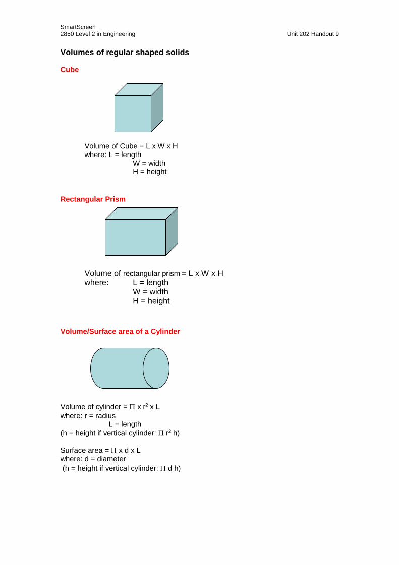
SmartScreen 2850 Level 2 in Engineering Unit 202 Handout 9 Volumes of regular shaped solids Cube
Volume of Cube = L x W x H where: L = length
W = width H = height
Rectangular Prism
Volume of rectangular prism = L x W x H where: L = length
W = width H = height
Volume/Surface area of a Cylinder Volume of cylinder = Π x r2 x L where: r = radius L = length (h = height if vertical cylinder: Π r2 h) Surface area = Π x d x L where: d = diameter (h = height if vertical cylinder: Π d h)

SmartScreen 2850 Level 2 in Engineering Unit 202 Handout 10
Unit 202: Principles of Engineering Technology Handout 10: Density Density is defined as the amount of mass in a particular volume. Mass is defined as the amount of matter in an object:
Density = Mass/Volume = kg/m3 For example liquid water has a density of 1000 kg/m3. When it freezes, its density changes to 920 kg/m3. (This is why water pipes burst when they freeze in the winter.) The density of steel is 7850 kg/m3. The density of stainless steel is 8300 kg/m3 Example A metal frame manufactured out of stainless steel has a volume of 0.5m3. What would be its approximate weight in kilograms?
Density = Mass / Volume Rearranging the formula:
Mass = Density x Volume Mass = 8300 x 0.5 = 4150 kgs
Relative density Relative density is a means of comparing the density of a material in comparison with that of water. Relative density has no units because it is a ratio. A value greater than one means that the material is more dense than water. a value less than one means that the material is less dense than water. The relative density of steel is 7850/1000 = 7.85 The relative density of stainless steel is 8300/1000 = 8.3 Material RD Material RD Material RD Material RD
Zinc 7.05 Mercury 13.61 Aluminium 2.7 Brass 8.56
Gold 19.3 Lead 11.35 Balsa Wood 0.2 Chromium 6.86
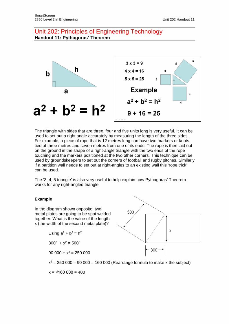
SmartScreen 2850 Level 2 in Engineering Unit 202 Handout 11
Unit 202: Principles of Engineering Technology Handout 11: Pythagoras’ Theorem The triangle with sides that are three, four and five units long is very useful. It can be used to set out a right angle accurately by measuring the length of the three sides. For example, a piece of rope that is 12 metres long can have two markers or knots tied at three metres and seven metres from one of its ends. The rope is then laid out on the ground in the shape of a right-angle triangle with the two ends of the rope touching and the markers positioned at the two other corners. This technique can be used by groundskeepers to set out the corners of football and rugby pitches. Similarly if a partition wall needs to set out at right-angles to an existing wall this ‘rope trick’ can be used. The ‘3, 4, 5 triangle’ is also very useful to help explain how Pythagoras’ Theorem works for any right-angled triangle. Example In the diagram shown opposite two metal plates are going to be spot welded together. What is the value of the length x (the width of the second metal plate)?
Using a2 + b2 = h2 3002 + x2 = 5002
90 000 + x2 = 250 000 x2 = 250 000 – 90 000 = 160 000 (Rearrange formula to make x the subject) x = √160 000 = 400
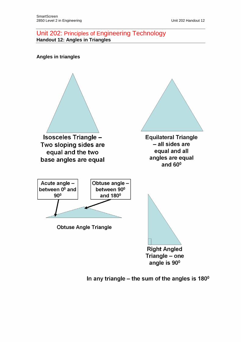
SmartScreen 2850 Level 2 in Engineering Unit 202 Handout 12
Unit 202: Principles of Engineering Technology Handout 12: Angles in Triangles Angles in triangles
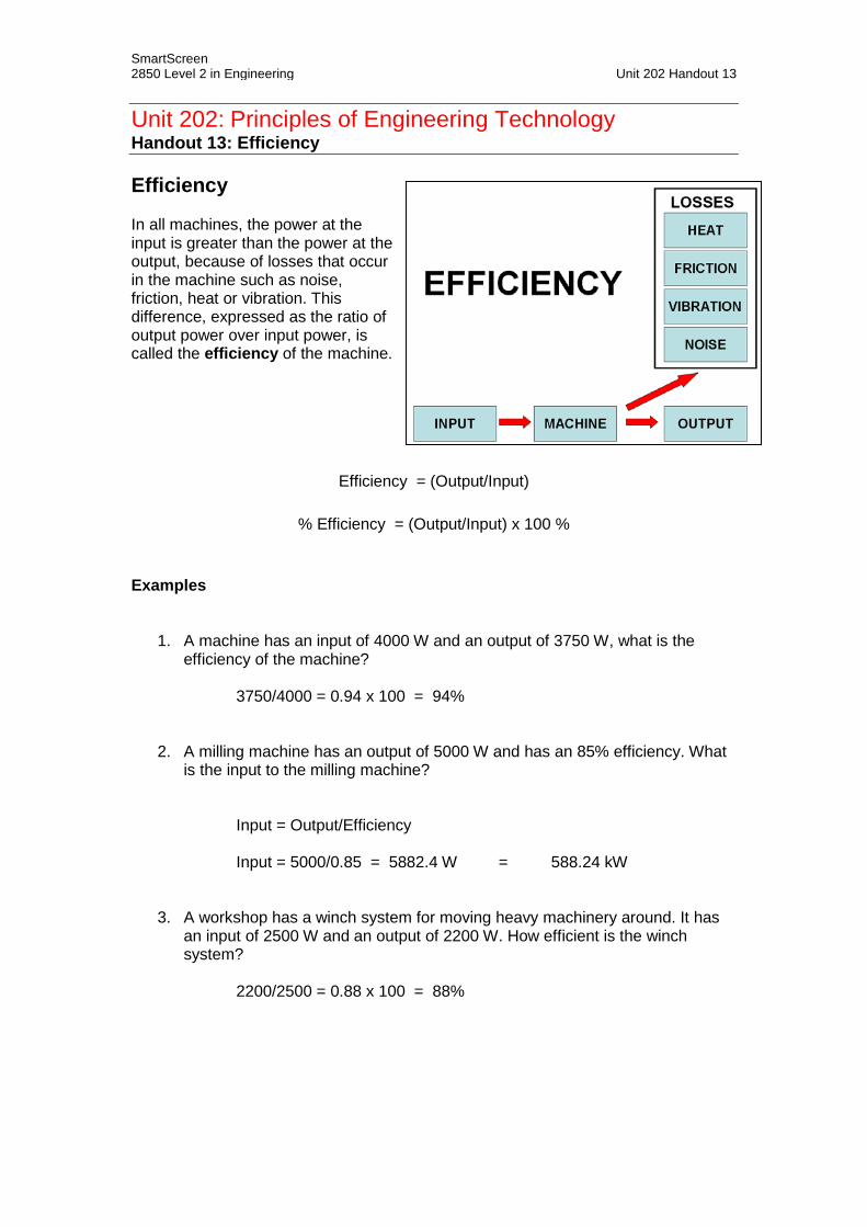
SmartScreen 2850 Level 2 in Engineering Unit 202 Handout 13
Unit 202: Principles of Engineering Technology Handout 13: Efficiency Efficiency In all machines, the power at the input is greater than the power at the output, because of losses that occur in the machine such as noise, friction, heat or vibration. This difference, expressed as the ratio of output power over input power, is called the efficiency of the machine.
Efficiency = (Output/Input)
% Efficiency = (Output/Input) x 100 %
Examples
1. A machine has an input of 4000 W and an output of 3750 W, what is the efficiency of the machine?
3750/4000 = 0.94 x 100 = 94%
2. A milling machine has an output of 5000 W and has an 85% efficiency. What is the input to the milling machine?
Input = Output/Efficiency Input = 5000/0.85 = 5882.4 W = 588.24 kW
3. A workshop has a winch system for moving heavy machinery around. It has an input of 2500 W and an output of 2200 W. How efficient is the winch system?
2200/2500 = 0.88 x 100 = 88%

SmartScreen 2850 Level 2 in Engineering Unit 202 Handout 14
Unit 202: Principles of Engineering Technology Handout 14: Work, Power and Energy Tasks 1. Define work done in terms of force and distance moved 2. Explain what is meant by energy 3. State the units for work, power and energy 4. Define power in terms of voltage and current 5. Perform calculations for the above Work is when a force is exerted to move an object over a distance. The unit for force is the newton (N) The unit for distance is the metre (m) Work done = force x distance (Fd) The unit for work done is the Joule (J), and 1 Nm = 1 J Example 1 You are pushing a very heavy stone block (200 kg) across the floor. You are exerting 620 N of force on the stone, and push it a total distance of 20 m before you get tired and stop. How much work did you just do? WD = 620 N x 20 m = 12 400 Nm And 1 Nm = 1 J So we did 12 400 J of work Therefore: WD = 620 N x 20 m = 12 400 J or 12.4 kJ Gravity When we were pushing something along the ground, the work done did not depend on the mass. When lifting up something the work does depend on mass, because of gravity. Gravity always pulls down with a force equal to mg, where m is the mass, and g = 10 m/s2 (acceleration due to gravity, 9.81 m/s2 to be precise). So we must exert at least that much force to lift something. The more mass something has, the more work required to lift it. So, work = force of gravity x distance = (mass x acceleration of gravity) x distance

SmartScreen 2850 Level 2 in Engineering Unit 202 Handout 14 Example 2 A weightlifter lifts a barbell with a mass of 280 kg a total of 2 metres off the floor. What is the minimum amount of work the weightlifter did? The barbell is ‘pulled’ down by gravity with a force of 280 kg x 10 m/s2 = 2800 N. So the weightlifter must exert at least 2800 N of force to lift the barbell at all. If that minimum force is used, the work done will be: WD = 2 800 N x 2 m = 5600 J or 5.6 kJ Power is the rate of doing work. Power = Work Done (J) / Time Spent Working (s)
Therefore Power =
work donetime
The unit of power is the watt (W). Example 3
It takes us 40 seconds to move that 200 kg block the 20 m. From our work done example we know that we did 12 400 J of work on the stone block to move it. From that we can determine the power…
Power =
work donetime
Power =
12 40040
Power = 310 W You do not have to determine the work done first when determining the power… Example 4 What is the power used when it takes 50 seconds for a force of 300 N to move an object through a distance of 45 m?
Power =
force x distancetime
Power =
300 x 4550
Power =
1350050
Power = 270 W

SmartScreen 2850 Level 2 in Engineering Unit 202 Handout 14 Energy is the capacity to do work. Energy is determined by multiplying the work done by the time taken. Energy = work done (J) x time (s) Therefore: energy = work done (WD) x time (t) And since work done = force x distance (Fd) Energy = WD x t or F x d x t The unit for energy is the same as for work, ie: the unit of energy is the Joule (J). Example 5 For the 200 kg stone block, the force exerted to move it 20 m was 640 N. If this took 40 seconds to complete, then the energy used would be… Energy = F x d x t = 640 x 20 x 40 = 512 000 J = 512 kJ Electrical power and energy Power (watt) is determined by the formula: Power = Voltage (V) x Current (I) Example 6 A welding machine uses 25 volts to maintain the arc and is set to 100 amps. Power = V x I Power = 25 V x 100 A Power = 2 500 W or 2.5 kW Energy is power x time Therefore for a one minute welding time: Energy = 2 500 W x 60 s = 150 000 J or 150 kJ

SmartScreen Level 2 Certificate/Diploma in Engineering Unit 202 Handout 15
Unit 202: Principles of Engineering Technology Handout 15: Areas and Volumes From the following diagrams of two regular shapes, calculate the area of each shape. (Show all your working.)
From the following diagrams of two regular solid bodies, calculate the volume of each shape. (Show all your working.) .
20cm
12cm
15cm
Formula Area of triangle =
Formula Area of a circle =
© 2015 City and Guilds of London Institute. All rights reserved. www.SmartScreen.co.uk

SmartScreen Level 2 Certificate/Diploma in Engineering Unit 202 Handout 15
From the following diagrams of two regular solid bodies, calculate the volume of each shape. (Show all your working.)
7m
18m
Formula Volume of cylinder =
10m
4m 5m
Formula Volume of a cube =
© 2015 City and Guilds of London Institute. All rights reserved. www.SmartScreen.co.uk

SmartScreen Level 2 Certificate/Diploma in Engineering Unit 202 Handout 15 a) From the following compound shapes, calculate the area of each. Identify each shape and write down the formulas required. Show all your working.
10cm
9cm
20cm Area =
10m
6m
8m
Area =
© 2015 City and Guilds of London Institute. All rights reserved. www.SmartScreen.co.uk

SmartScreen Level 2 Certificate/Diploma in Engineering Unit 202 Handout 15 Calculate the volume of each of the following compound solid bodies Identify each shape and write down the formulas required. Show all your working.
5cm
8cm
7cm
Formulas for Volume =
10m
4m
7m
3m
Formula for Volume =
© 2015 City and Guilds of London Institute. All rights reserved. www.SmartScreen.co.uk

SmartScreen 2850 Level 2 in Engineering Unit 202 Worksheet 1
Unit 202: Principles of Engineering Technology Worksheet 1: Choosing Materials Everything made, must be made from some sort of material. The choice of material is very important. In order to make this choice you need to know the properties of the material. Once these and other questions have been answered, you will be able to choose a suitable material. Complete the table below, to describe the common engineering metals: Material Colour and
melting point
Composition Properties Uses Common Forms
Aluminium
Light grey Pure metal
Copper
Brass
980°C
Commonly: 65% copper 35% zinc (but composition varies)
SmartScreen 2850 Level 2 in Engineering Unit 202 Worksheet 1
Low-carbon steel (Mild steel)
Medium-carbon steel
High-carbon steel
Cast iron
Stainless steels

SmartScreen 2850 Level 2 in Engineering Unit 202 Worksheet 2
Unit 202: Principles of Engineering Technology Worksheet 2: Numerical Calculations Fractions expressed as decimals Examples: Change the following fractions to decimals:
1. 1/5 = 1 ÷ 5 = 0.2 2. 11/20 = 11 ÷ 20 = 0.55 Convert the fractions below to decimals:
1. 1/4 = 2. 1/2 = 3. 3/4 =
4. 1/10 = 5. 3/10 = 6. 7/10 =
7. 2/5 = 8. 3/5 = 9. 4/5 =
10. 3/20 = 11. 7/20 = 12. 19/20 =
13. 4/25 = 14. 9/25 = 15. 23/25 =
16. 7/100 = 17. 23/100 = 18. 106/200 =
19. 1/8 = 20. 5/8 = 21. 9/40 = Rounding using significant figures Example: What is the area of a sheet of aluminium measuring 4.6 cm by 7.2 cm?
4.6 x 7.2 = 33.12 cm2
Since the measurements used in the calculation (4.6 cm and 7.2 cm) are given to two significant figures the answer should be as well. 33 cm2 is a more sensible answer. Round using significant figures:
Number Sig. Fig.
Answer Number Sig. Fig. Answer
456 000 2 0.000567 2
454 000 2 0.093748 2
7 981 234 3 0.093748 3
7 981 234 2 0.093748 4
1290 2 0.010245 2
19 602 1 0.02994 2

SmartScreen 2850 Level 2 in Engineering Unit 202 Worksheet 3
Unit 202: Principles of engineering technology Worksheet 3: Efficiency calculations
Remember: Efficiency =
OutputInput
x 100 %
Now complete the tables below to determine the required/missing quantities relating to a motor operating at a particular level of efficiency:
Question 1 2 3 4
Input 120 W 15 W W 1 kW
Output W 12 W 250 W W
Efficiency 80% % 50% 97%
Question 5 6 7 8
Input 101 W MW 27 W 220 W
Output 100 W 1.5 MW W 215 W
Efficiency % 75% 66.666% %

SmartScreen 2850 Level 2 in Engineering Unit 202 Worksheet 3
Question 9 10 11 12
Input W 350 W 2 kW W
Output 450 W W 1.8 kW 0.9 W
Efficiency 75% 70% % 40%
Question 13 14 15 16
Input 1500 W MW 600 W 20 W
Output 1000 W 3 MW W 15 W
Efficiency % 75% 45% %
Question 17 18 19 20
Input 45 W MW 270 W 220 W
Output 40.05 W 6 MW W 180.4 W
Efficiency % 80% 90% %

SmartScreen 2850 Level 2 in Engineering Unit 202 Worksheet 4
Unit 202: Principles of Engineering Technology Worksheet 4: Tolerance Calculations Engineering tolerance is the permissible limit of variation in a physical dimension. Tolerance is the difference between the upper and lower limits of the dimensions (limits of size) to which components need to be made. Now complete the tables below to determine the required/missing quantities relating to a set of metal rods being checked by a quality inspector to ensure that the rods are being manufactured accurately. Which ones should be rejected? Examples
DESIRED VALUE
TOLERANCE UPPER LIMIT
LOWER LIMIT
ACTUAL VALUE
ACCEPT
20 mm ± 10 % 22 mm 18 mm 17 mm NO 32 mm ± 5 % 33.6 mm 30.4 mm 31.1 mm YES 14 mm ± 20 % 16. 8 mm 11.2 mm 17.1 mm NO
DESIRED VALUE
TOLERANCE UPPER LIMIT
LOWER LIMIT
ACTUAL VALUE
ACCEPT
25 mm ± 15 % mm mm 28 mm YES / NO
75 mm ± 5 % mm mm 79 mm YES / NO
16 mm ± 2 % mm mm 17 mm YES / NO
42 mm ± 7.5 % mm mm 45.1 mm YES / NO
60 mm ± 10 % mm mm 65.3 mm YES / NO
18 mm ± 5 % mm mm 19 mm YES / NO
55 mm ± 10 % mm mm 60.4 mm YES / NO
95 mm ± 12.5 % mm mm 106 mm YES / NO
24 mm ± 20 % mm mm 19.7 mm YES / NO
36 mm ± 3 % mm mm 37.1 mm YES / NO
12 mm ± 10 % mm mm 10.7 mm YES / NO
45 mm ± 5 % mm mm 47.6 mm YES / NO
85 mm ± 5 % mm mm 89.1 mm YES / NO

SmartScreen 2850 Level 2 in Engineering Unit 202 Worksheet 5
Unit 202: Principles of Engineering Technology Worksheet 5: Work, Power and Energy Problems
1. Determine the work done when a force of 600 N acts through a distance of 30 m.
2. Determine the work done when a force of 20 kN acts through a distance of 3 mm.
3. A mass of 100 kg is raised vertically through a height of 8 m. Find the work done on the
mass.
(NOTE: to find the force we must first multiple the mass in kg by gravity, i.e. 10 m/s2.)
4. If the work energy expended in moving a body through a distance of 50 m is 400 J,
determine the force required.
5. A machine of mass 1 tonne (1000 kg) is raised 150 mm by means of a screwjack.
Determine the work done on the body.
(NOTE: to find the force we must first multiple the mass in kg by gravity, i.e. 10 m/s2.)
6. A load of mass 800 kg is lifted by 6 m in 12 seconds. Calculate the power. (NOTE: to
find the force we must first multiple the mass in kg by gravity, i.e. 10 m/s2.)

SmartScreen Level 2 Certificate/Diploma in Engineering Unit 202 Worksheet 5 7. A force of 400 N is used to move an object 30 m across the floor. The time taken to
complete this is 2 minutes. Determine:
a. the work done
b. the power
c. the energy used
8. A mass of 1 tonne (1000 kg) is lifted vertically through a height of 6 m in 4 minutes.
Determine:
a. the work done
b. the power
c. the energy used.
(REMEMBER that to find the force we must first multiple the mass in kg by gravity, i.e. 10
m/s2.)

SmartScreen 2850 Level 2 in Engineering Unit 202 Worksheet
Unit 202: Principles of Engineering Technology Worksheet 6: Material Properties and their Identification
Individual activity
Suggested time for this activity: 60 to 90 minutes depending on the equipment and number of samples available.
From the samples provided by your tutor, identify the following materials:
a. Copperb. Mild steelc. Aluminiumd. Cast irone. Ceramicf. Leadg. Stainless steel
For each material, complete the following chart:
Copper Mild steel Aluminium Cast
Iron Ceramic Lead Stainlesssteel
Colour
Density
Texture
Hardness
Elasticity
Plasticity
Malleability
Magnetism

SmartScreen 2850 Level 2 in Engineering Unit 202 Worksheet 7
Unit 202: Principles of Engineering Technology Worksheet 7: Material Supply and Applications Small group activity Suggested time for this activity: 20 minutes Working in small groups, discuss the possible ways materials can be supplied. Then indicate on the grid below with a cross, which materials are supplied in which format. Two crosses have already been allocated to give you a start.
Mild Steel Plastic Ceramic Copper Wood Lead
Bar/section X
Sheet
Wire
Plate
Casts/mouldings
Forgings
Extrusions
Pipe X
Granules
Powders
Liquids
Tube Towards the end of the activity the group may discuss any uncertainties with the tutor.

SmartScreen 2850 Level 2 in Engineering Unit 202 Worksheet 7
Individual activity
Suggested time for this activity: 20 minutes
Indicate on the grid below with a cross, which materials are used for the manufactured products listed. One cross has already been allocated to give you a start.
Steel Plastic Ceramic Copper Silicon Tin
Ball bearings X
Solder
Diodes
Electrical wiring
Calculator case
Electric drill
Rag bolt
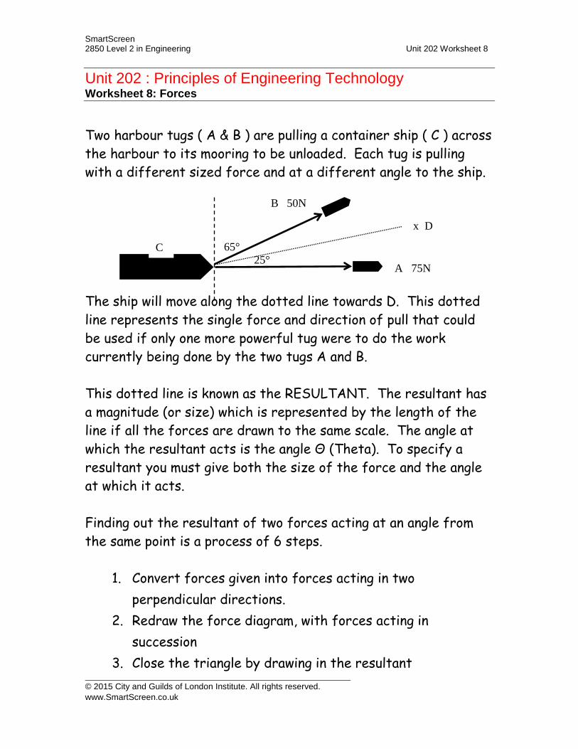
SmartScreen 2850 Level 2 in Engineering Unit 202 Worksheet 8
Unit 202 : Principles of Engineering Technology Worksheet 8: Forces Two harbour tugs ( A & B ) are pulling a container ship ( C ) across the harbour to its mooring to be unloaded. Each tug is pulling with a different sized force and at a different angle to the ship. The ship will move along the dotted line towards D. This dotted line represents the single force and direction of pull that could be used if only one more powerful tug were to do the work currently being done by the two tugs A and B. This dotted line is known as the RESULTANT. The resultant has a magnitude (or size) which is represented by the length of the line if all the forces are drawn to the same scale. The angle at which the resultant acts is the angle Θ (Theta). To specify a resultant you must give both the size of the force and the angle at which it acts. Finding out the resultant of two forces acting at an angle from the same point is a process of 6 steps.
1. Convert forces given into forces acting in two perpendicular directions.
2. Redraw the force diagram, with forces acting in succession
3. Close the triangle by drawing in the resultant
A 75N
B 50N
C 25°
65°
x D
© 2015 City and Guilds of London Institute. All rights reserved. www.SmartScreen.co.uk

SmartScreen 2850 Level 2 in Engineering Unit 202 Worksheet 8
4. Calculate the size of the resultant5. Find the angle at which the resultant is acting6. State the resultant by defining its magnitude and
direction
STEP 1 Convert forces given into forces acting in two perpendicular directions:
The two directions we choose are usually vertically (or North) and horizontally (or East).
In our example with the tug boats the force CA (75N) is already acting horizontally and to the East.
The force CB (50N) can be split into two forces, one acting North and the other acting East. Not all of the force CB acts in an East direction. To find out how much of it acts to the East we multiply the force by the cosine of the angle it has to rotate through to come into line with East:
CB > = 50 x cos25° CB > = 50 x 0.643 CB > = 32.15N
Similarly to find out how much of the force CB acts to the North, again we multiply the force by the cosine of the angle it has to rotate through to come into line with North:
CB ^ = 50 x cos65° CB ^ = 50 x 0.423 CB ^ = 21.15N
© 2015 City and Guilds of London Institute. All rights reserved. www.SmartScreen.co.uk

SmartScreen 2850 Level 2 in Engineering Unit 202 Worksheet 8
Looking at all the forces acting East, we have: > CA + CB x cos25° > 75 + 50 x cos25° > 75 + 32.15 > 107.15N
The bigger the angle a force has to turn through then the weaker that force gets, until at 90° to its original direction the force has become zero. Looking at all the forces acting North, we have:
^ CA x cos90° + CB x cos65° ^ 75 x 0 + 50 x 0.423 ^ 0 + 21.15 ^ 21.15N
We have now converted the original forces given in the question into two equivalent forces which act a right angles to each other: STEP 2 Redraw the force diagram, with forces acting in succession:
107.15N
21.15N
107.15N
21.15N
© 2015 City and Guilds of London Institute. All rights reserved. www.SmartScreen.co.uk
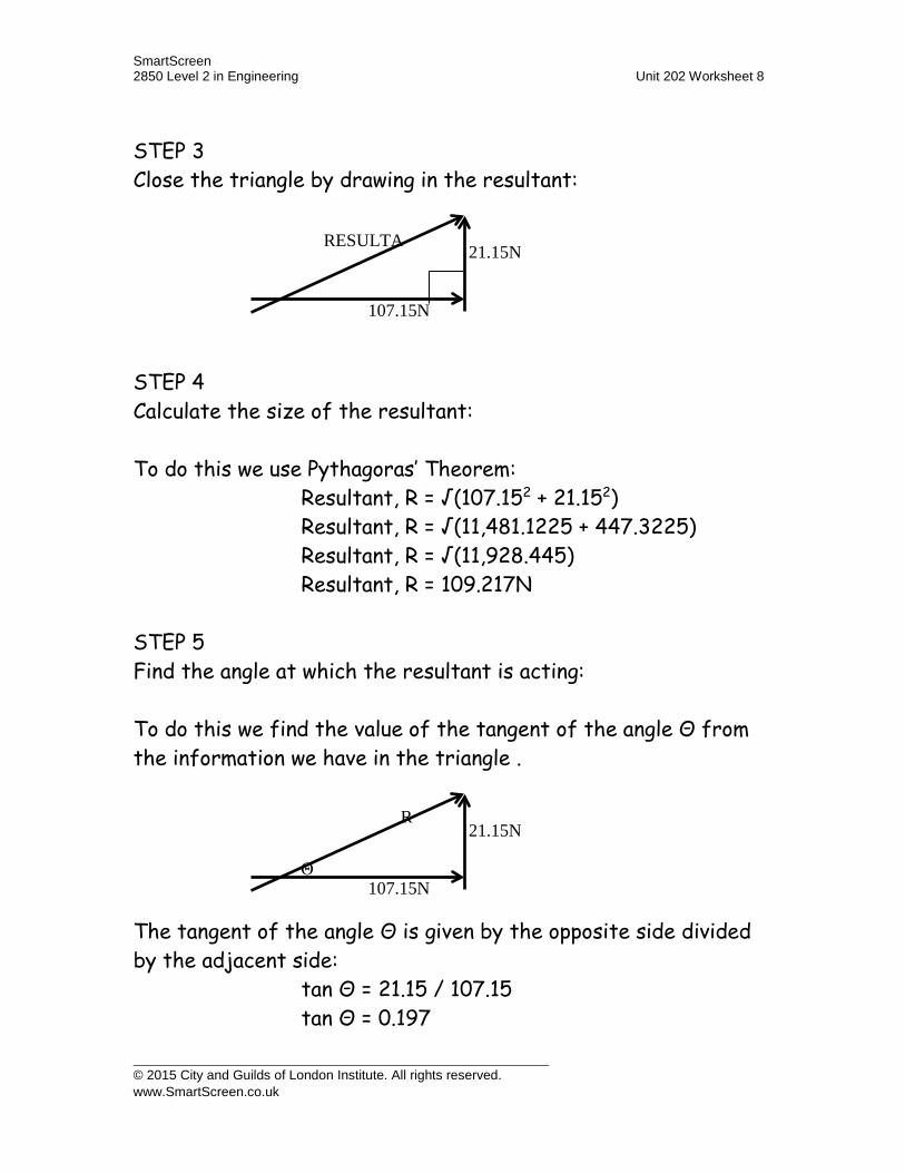
SmartScreen 2850 Level 2 in Engineering Unit 202 Worksheet 8
STEP 3 Close the triangle by drawing in the resultant: STEP 4 Calculate the size of the resultant: To do this we use Pythagoras’ Theorem:
Resultant, R = √(107.152 + 21.152) Resultant, R = √(11,481.1225 + 447.3225) Resultant, R = √(11,928.445) Resultant, R = 109.217N
STEP 5 Find the angle at which the resultant is acting: To do this we find the value of the tangent of the angle Θ from the information we have in the triangle . The tangent of the angle Θ is given by the opposite side divided by the adjacent side:
tan Θ = 21.15 / 107.15 tan Θ = 0.197
107.15N
21.15N RESULTA
107.15N
21.15N R
Θ
© 2015 City and Guilds of London Institute. All rights reserved. www.SmartScreen.co.uk

SmartScreen 2850 Level 2 in Engineering Unit 202 Worksheet 8
But, we need to find Θ, not tan Θ, so Θ is the angle whose tangent is 0.197
Θ = tan-1 ( 0.197 ) To do tan-1 you will need to use the “SHIFT” or “2ndF” button on your calculator
Θ = 11.145° STEP 6 State the resultant by defining its magnitude and direction:
The Resultant is a force of 109.217N which acts at an angle of +11.145° to the horizontal.
NOTE: Here we have called the angle +11.145°, this is because the accepted convention is that angles which are north of east are treated as positive, whilst angles south of east are treated as negative.
Alternatively, you could give the angle as a compass bearing (the direction that the tug captain of the single tug would have to steer on his compass in order to move the container ship):
The Resultant is a force of 109.217N at a bearing of 078.855° (90° - 11.145°)
R
11.145°
R
078.855°
© 2015 City and Guilds of London Institute. All rights reserved. www.SmartScreen.co.uk
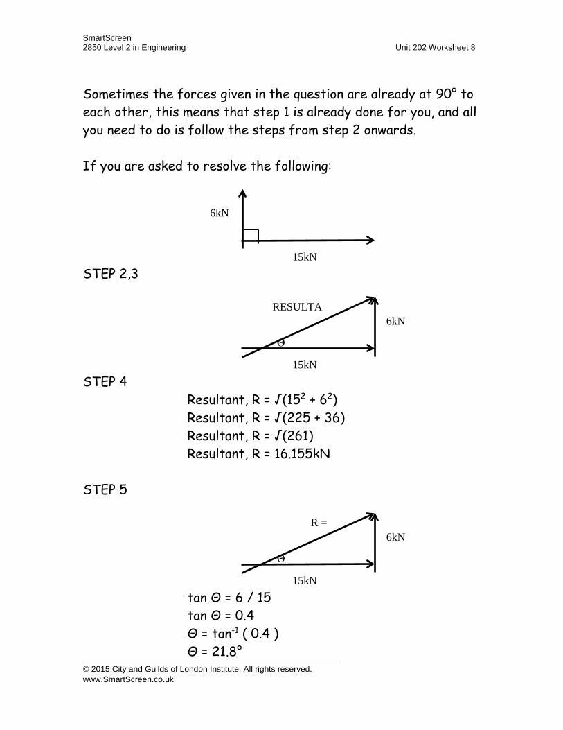
SmartScreen 2850 Level 2 in Engineering Unit 202 Worksheet 8
Sometimes the forces given in the question are already at 90° to each other, this means that step 1 is already done for you, and all you need to do is follow the steps from step 2 onwards. If you are asked to resolve the following: STEP 2,3 STEP 4
Resultant, R = √(152 + 62) Resultant, R = √(225 + 36) Resultant, R = √(261) Resultant, R = 16.155kN
STEP 5
tan Θ = 6 / 15 tan Θ = 0.4 Θ = tan-1 ( 0.4 ) Θ = 21.8°
15kN
6kN
15kN
6kN RESULTA
Θ
15kN
6kN R =
Θ
© 2015 City and Guilds of London Institute. All rights reserved. www.SmartScreen.co.uk

SmartScreen 2850 Level 2 in Engineering Unit 202 Worksheet 8
STEP 6
The Resultant is a force of 16.155kN which acts at an angle of +21.8° to the horizontal.
or
The Resultant is a force of 16.155kN at a bearing of 068.2° (68.2° - 21.8°)
Sometimes you will need to resolve forces looking like this. Again we follow the steps from 1 through 6. Looking at all the forces acting East, we have:
> 89 + 57 x cos27° > 89 + 50.787 > 139.787N
R =
21.8
R =
68.2
27°
57N
89N
© 2015 City and Guilds of London Institute. All rights reserved. www.SmartScreen.co.uk

SmartScreen 2850 Level 2 in Engineering Unit 202 Worksheet 8
Looking at all the forces acting North, we have:
^ 89 x cos 90° - 57 x cos63° ^ 89 x 0 + 57 x 0.454 ^ 0 - 25.878 ^ - 25.878N
as this is negative it means that the force is +25.878N acting South. STEP 2 & 3 STEP 4
Resultant, R = √(139.7872 + 25.8782) Resultant, R = √(19540.405 + 669.671) Resultant, R = √(20210.076) Resultant, R = 142.162N
139.787N
25.878N RESULTA
© 2015 City and Guilds of London Institute. All rights reserved. www.SmartScreen.co.uk
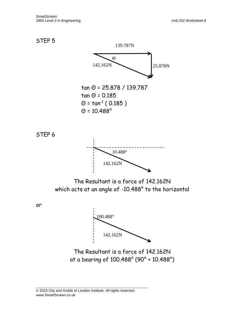
SmartScreen 2850 Level 2 in Engineering Unit 202 Worksheet 8
STEP 5
tan Θ = 25.878 / 139.787 tan Θ = 0.185 Θ = tan-1 ( 0.185 ) Θ = 10.488°
STEP 6
The Resultant is a force of 142.162N which acts at an angle of -10.488° to the horizontal
or
The Resultant is a force of 142.162N at a bearing of 100.488° (90° + 10.488°)
139.787N
25.878N 142.162N Θ
142.162N
10.488°
142.162N
100.488°
© 2015 City and Guilds of London Institute. All rights reserved. www.SmartScreen.co.uk

SmartScreen 2850 Level 2 in Engineering Unit 202 Worksheet 8
Occasionally you may have to deal with more than 2 forces, and you may be asked to find an equilibrant.
An equilibrant is a force which if added into your system of forces would give you an overall resultant of zero. Therefore the equilibrant is equal in size to your resultant but acts in the opposite direction to it.
Resolve the following system of forces and find the equilibrant:
STEP 1
Looking at all the forces acting East, we have: > -7 + 5 x cos25° + 3 x cos70°> -7 + 5 x 0.906 + 3 x 0.342> -7 + 4.532 + 1.026> -1.442N
as this is negative it means that the force is +1.442N acting West.
7N
5N
3N
155° 95°
7N
5N
3N
65 25
70°
20°
© 2015 City and Guilds of London Institute. All rights reserved. www.SmartScreen.co.uk

SmartScreen 2850 Level 2 in Engineering Unit 202 Worksheet 8
Looking at all the forces acting North, we have: ^ 7 x cos90° + 5 x cos65° - 3 x cos20° ^ 7 x 0 + 5 x 0.423 – 3 x 0.940 ^ 0 + 2.115 – 2.82 ^ -0.705N
as this is negative it means that the force is +0.705N acting South.
STEP 2,3
STEP 4 Resultant, R = √(1.4422 + 0.7052) Resultant, R = √(2.079364 + 0.497025) Resultant, R = √(2.576389) Resultant, R = 1.605N
STEP 5
tan Θ = 0.705 / 1.442 tan Θ = 0.489 Θ = tan-1 ( 0.489 ) Θ = 26.054°
RESULTA
1.442N
0.705N
1.605N 0.705N
1.442N Θ
© 2015 City and Guilds of London Institute. All rights reserved. www.SmartScreen.co.uk

SmartScreen 2850 Level 2 in Engineering Unit 202 Worksheet 8
STEP 6
The Resultant is a force of 1.605N which acts at an angle of -153.946° to the horizontal.
The Resultant is a force of 109.217N at a bearing of 243.946° (90° + 153.946°).
STEP 7 Finding the Equilibrant:
The equilibrant is the force which is equal and opposite to the resultant force. The size of the equilibrant force is the same as the size of the resultant force, but it acts in the opposite direction in order to cancel out the system of forces to zero.
The Resultant is a force of 109.217N at a bearing of 243.946° (90° + 153.946°)
The Equilibrant is a force of 109.217N at a bearing of 063.946° (243.946° - 180°)
1.605N 153.946
1.605N 243.946
© 2015 City and Guilds of London Institute. All rights reserved. www.SmartScreen.co.uk

Please bring your completed workbook with you when you attend class.
When you have studied this material please contact us to makearrangements for your practical training.