2850 DIPLOMA IN ENGINEERING FABRICATION AND WELDING ... · 2850. diploma in engineering....
18
2850 DIPLOMA IN ENGINEERING FABRICATION AND WELDING TECHNOLOGY PRE-ATTENDANCE REVISION WORKBOOK FOR UNIT 213 V1
Transcript of 2850 DIPLOMA IN ENGINEERING FABRICATION AND WELDING ... · 2850. diploma in engineering....
2850
DIPLOMA IN ENGINEERING
FABRICATION AND WELDING TECHNOLOGY
PRE-ATTENDANCE REVISION WORKBOOK FOR
UNIT 213
V1

Welcome
This booklet is designed to outline the areas that you will study when you complete unit 213 at the centre.
Throughout your time in centre you will have a qualified assessor there to help and advise you.
We want you to achieve the best possible benefits from your time in centre, therefore before attending we would like you to revise by carrying out the work detailed in this booklet.
Please remember that you should not carry out any welding practical work unless you are in class with one of our qualified assessors.
Please bring your completed workbook with you when you attend in class.
We very much look forward to welcoming you at the centre.
When you have studied this material please contact us to make arrangements for your practical training.

Date:
Title First name Last name College number
Please complete this page before attending the centre as there will be many other students who have this same workbook.
You do not need to leave this workbook at the centre. You can take it home with you and retain it for your future reference.
SmartScreen Level 2 Certificate/Diploma in Engineering Unit 213 Handout 1
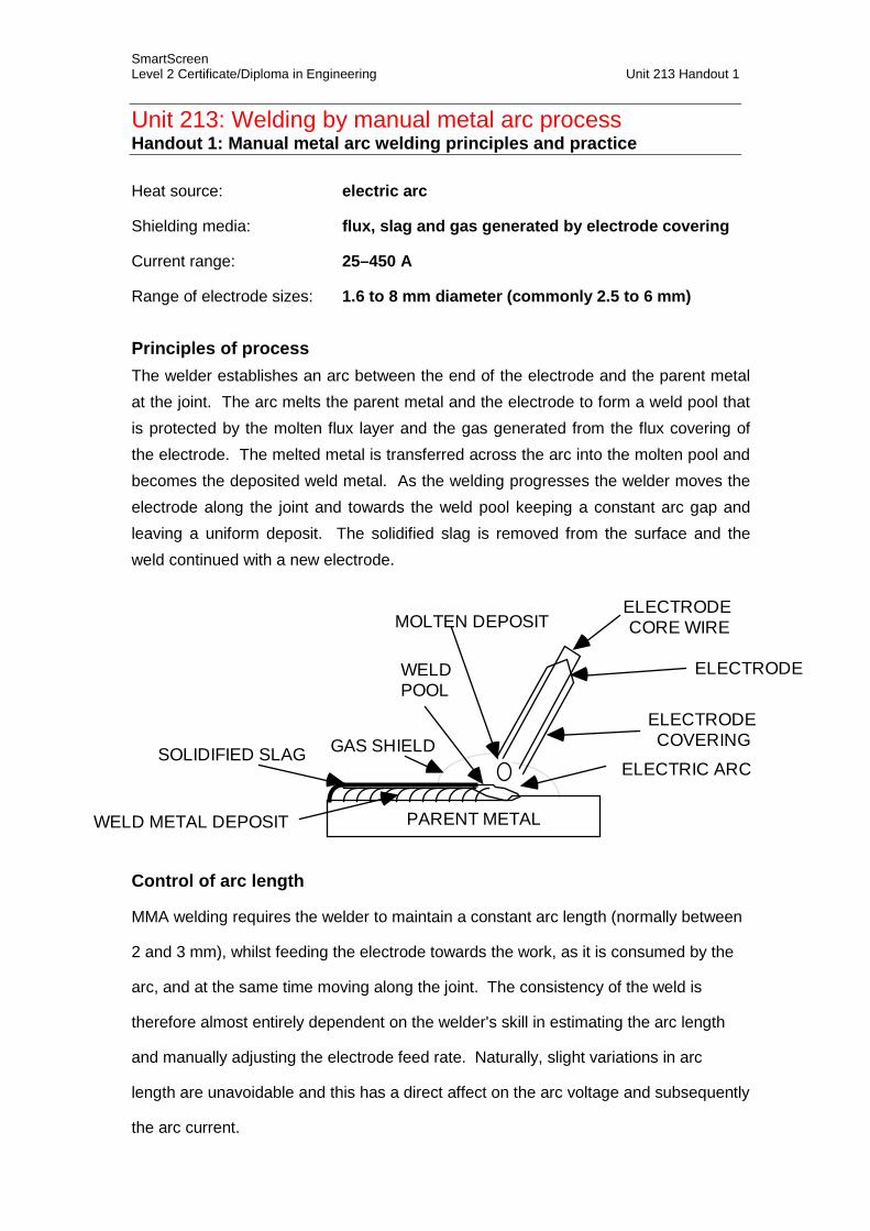
Unit 213: Welding by manual metal arc process Handout 1: Manual metal arc welding principles and practice
Heat source: electric arc
Shielding media: flux, slag and gas generated by electrode covering
Current range: 25–450 A
Range of electrode sizes: 1.6 to 8 mm diameter (commonly 2.5 to 6 mm)
Principles of process The welder establishes an arc between the end of the electrode and the parent metal at the joint. The arc melts the parent metal and the electrode to form a weld pool that is protected by the molten flux layer and the gas generated from the flux covering of the electrode. The melted metal is transferred across the arc into the molten pool and becomes the deposited weld metal. As the welding progresses the welder moves the electrode along the joint and towards the weld pool keeping a constant arc gap and leaving a uniform deposit. The solidified slag is removed from the surface and the weld continued with a new electrode.
ELECTRODE CORE WIRE
ELECTRODE COVERING
ELECTRIC ARC
WELD POOL
GAS SHIELDSOLIDIFIED SLAG
WELD METAL DEPOSIT
MOLTEN DEPOSIT
PARENT METAL
ELECTRODE
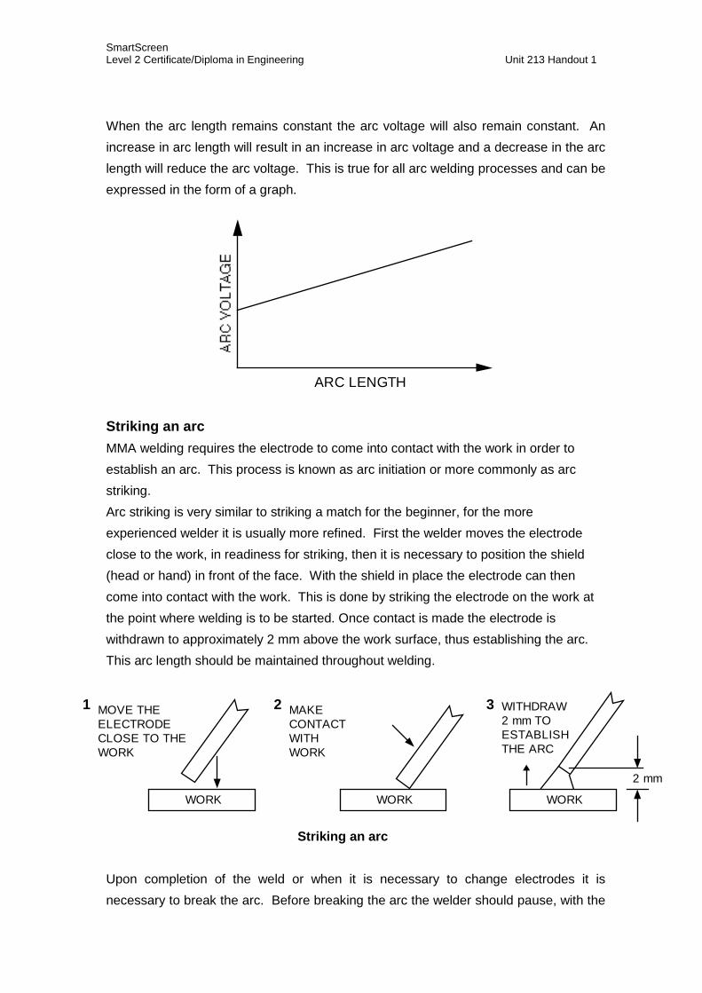
Control of arc length
MMA welding requires the welder to maintain a constant arc length (normally between
2 and 3 mm), whilst feeding the electrode towards the work, as it is consumed by the
arc, and at the same time moving along the joint. The consistency of the weld is
therefore almost entirely dependent on the welder's skill in estimating the arc length
and manually adjusting the electrode feed rate. Naturally, slight variations in arc
length are unavoidable and this has a direct affect on the arc voltage and subsequently
the arc current.
SmartScreen Level 2 Certificate/Diploma in Engineering Unit 213 Handout 1
When the arc length remains constant the arc voltage will also remain constant. An increase in arc length will result in an increase in arc voltage and a decrease in the arc length will reduce the arc voltage. This is true for all arc welding processes and can be expressed in the form of a graph.
ARC LENGTH
Striking an arc MMA welding requires the electrode to come into contact with the work in order to establish an arc. This process is known as arc initiation or more commonly as arc striking. Arc striking is very similar to striking a match for the beginner, for the more experienced welder it is usually more refined. First the welder moves the electrode close to the work, in readiness for striking, then it is necessary to position the shield (head or hand) in front of the face. With the shield in place the electrode can then come into contact with the work. This is done by striking the electrode on the work at the point where welding is to be started. Once contact is made the electrode is withdrawn to approximately 2 mm above the work surface, thus establishing the arc. This arc length should be maintained throughout welding.
1 MOVE THEELECTRODE CLOSE TO THE WORK
2 MAKECONTACT WITH WORK
3 WITHDRAW2 mm TO ESTABLISH THE ARC
WORK WORK
2 mm
WORK
Striking an arc
Upon completion of the weld or when it is necessary to change electrodes it is necessary to break the arc. Before breaking the arc the welder should pause, with the

SmartScreen Level 2 Certificate/Diploma in Engineering Unit 213 Handout 1
electrode held in position long enough to build up the weld pool, then simply move the electrode away from the work surface quickly. Building up of the weld pool avoids cavities, fine cracks and porosity defects in the solidified weld pool.
CONCAVE CRATER CONVEX CRATER AFTER BUILD-UP
Filling a crater
SmartScreen Level 2 Certificate/Diploma in Engineering Unit 213 Handout 2
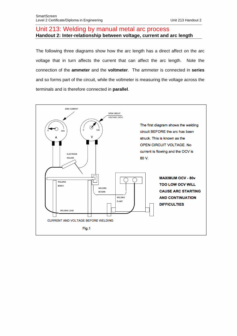
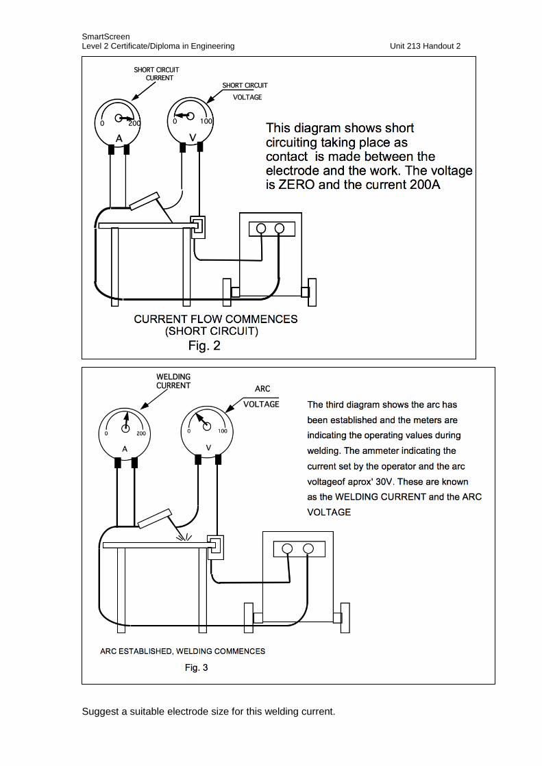
Unit 213: Welding by manual metal arc process Handout 2: Inter-relationship between voltage, current and arc length
The following three diagrams show how the arc length has a direct affect on the arc
voltage that in turn affects the current that can affect the arc length. Note the
connection of the ammeter and the voltmeter. The ammeter is connected in series
and so forms part of the circuit, while the voltmeter is measuring the voltage across the
terminals and is therefore connected in parallel.
SmartScreen Level 2 Certificate/Diploma in Engineering Unit 213 Handout 2
Suggest a suitable electrode size for this welding current.
SmartScreen Level 2 Certificate/Diploma in Engineering Unit 213 Handout 3
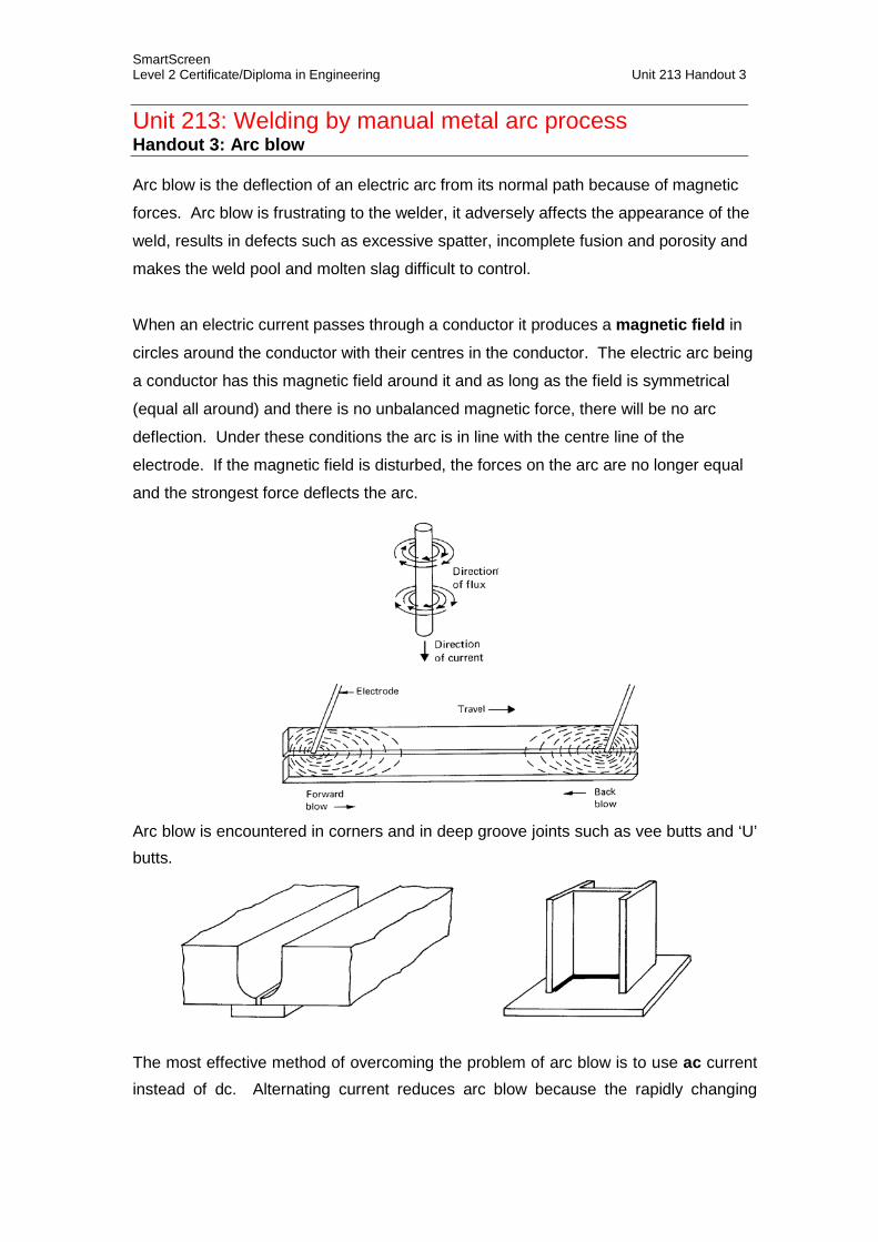
Unit 213: Welding by manual metal arc process Handout 3: Arc blow Arc blow is the deflection of an electric arc from its normal path because of magnetic
forces. Arc blow is frustrating to the welder, it adversely affects the appearance of the
weld, results in defects such as excessive spatter, incomplete fusion and porosity and
makes the weld pool and molten slag difficult to control.
When an electric current passes through a conductor it produces a magnetic field in
circles around the conductor with their centres in the conductor. The electric arc being
a conductor has this magnetic field around it and as long as the field is symmetrical
(equal all around) and there is no unbalanced magnetic force, there will be no arc
deflection. Under these conditions the arc is in line with the centre line of the
electrode. If the magnetic field is disturbed, the forces on the arc are no longer equal
and the strongest force deflects the arc.
Arc blow is encountered in corners and in deep groove joints such as vee butts and ‘U’ butts.
The most effective method of overcoming the problem of arc blow is to use ac current instead of dc. Alternating current reduces arc blow because the rapidly changing
SmartScreen Level 2 Certificate/Diploma in Engineering Unit 213 Handout 3
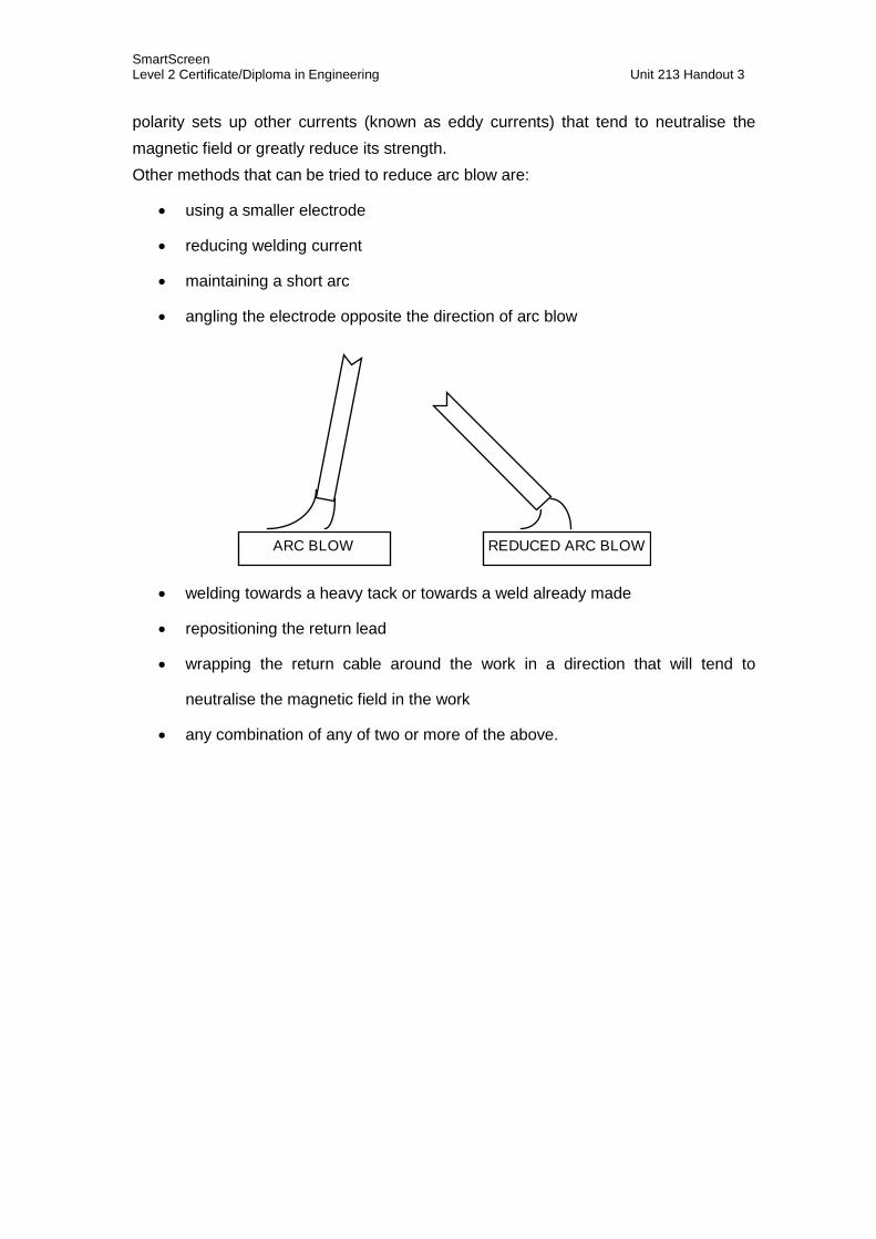
polarity sets up other currents (known as eddy currents) that tend to neutralise the magnetic field or greatly reduce its strength. Other methods that can be tried to reduce arc blow are:
• using a smaller electrode
• reducing welding current
• maintaining a short arc
• angling the electrode opposite the direction of arc blow
REDUCED ARC BLOWARC BLOW
• welding towards a heavy tack or towards a weld already made
• repositioning the return lead
• wrapping the return cable around the work in a direction that will tend to
neutralise the magnetic field in the work
• any combination of any of two or more of the above.
SmartScreen Level 2 Certificate/Diploma in Engineering Unit 213 Handout 3
Unit 213: Welding by manual metal arc process Handout 4: Electrodes
An electrode for MMA welding is a coated metal wire of compatible composition to the
metal(s) to be welded. During welding an arc is formed between the electrode and the
base metal. The molten electrode deposits into the weld pool and can form a bond
between two pieces of metal.
Electrodes are available for various metals, they come in a range of different types and
sizes to suit different output currents (dc or ac/dc) and welding positions (flat and horizontal/vertical or all positions). These factors and a number of other factors are
considered during electrode selection.
Factors influencing electrode selection: • mechanical properties
• type of coating
• welding position
• electrical requirements
• rate of weld deposition
• surface appearance
• type of penetration
• metal recovery rate.
These requirements are reflected in BS EN ISO 2560: 2005 that deals with the
welding consumables, covered electrodes for manual metal arc welding of non alloy
and fine grain steels and classification.
Electrode classification This standard details a system by which electrodes can be given a code number. This
makes it easier to identify the different types without using trade names.
The classification is divided into eight parts.
1 The symbol indicating the product/process used.
2 The symbol indicating strength and elongation of the weld metal.
3 The symbol indicating the impact properties of the weld metal.
4 The symbol indicating the chemical composition of the weld metal.
5 The symbol indicating the type of the electrode covering.
6 The symbol indicating the recovery rate and current type.
7 The symbol indicating the welding position.
8 The symbol indicating the hydrogen content of the deposit.
SmartScreen Level 2 Certificate/Diploma in Engineering Unit 213 Handout 3
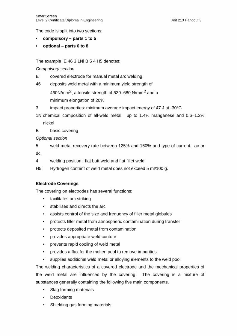
The code is split into two sections:
• compulsory – parts 1 to 5
• optional – parts 6 to 8
The example E 46 3 1Ni B 5 4 H5 denotes:
Compulsory section E covered electrode for manual metal arc welding
46 deposits weld metal with a minimum yield strength of
460N/mm2, a tensile strength of 530–680 N/mm2 and a
minimum elongation of 20%
3 impact properties: minimum average impact energy of 47 J at -30°C
1Ni chemical composition of all-weld metal: up to 1.4% manganese and 0.6–1.2%
nickel
B basic covering
Optional section
5 weld metal recovery rate between 125% and 160% and type of current: ac or
dc.
4 welding position: flat butt weld and flat fillet weld
H5 Hydrogen content of weld metal does not exceed 5 ml/100 g.
Electrode Coverings The covering on electrodes has several functions:
• facilitates arc striking
• stabilises and directs the arc
• assists control of the size and frequency of filler metal globules
• protects filler metal from atmospheric contamination during transfer
• protects deposited metal from contamination
• provides appropriate weld contour
• prevents rapid cooling of weld metal
• provides a flux for the molten pool to remove impurities
• supplies additional weld metal or alloying elements to the weld pool
The welding characteristics of a covered electrode and the mechanical properties of
the weld metal are influenced by the covering. The covering is a mixture of
substances generally containing the following five main components.
• Slag forming materials
• Deoxidants
• Shielding gas forming materials
SmartScreen Level 2 Certificate/Diploma in Engineering Unit 213 Handout 3
• Ionising agents
(to maintain a stable arc, particularly when using ac)
• Binders (to hold the component parts together)
As previously stated additional alloying elements can also be included in the covering
if required. There are four main groups of electrodes used in MMA welding of steels:
• cellulosic
• rutile
• basic
• acid.
Cellulosic covering contains organic materials (flour and wood pulp are common
constituents) that decomposed in the arc to generate hydrogen. The presence of
hydrogen increases the arc voltage which makes the arc more forceful and results in
greater penetration. Cellulosic electrodes are sometimes referred to as deep penetration electrodes or DPs and are used for the ‘stovepipe’ – vertical-down
welding technique. Because most of the flux decomposes, the resultant slag layer is
thin and easy to remove (wire brushing is a good method). The surface appearance is
poor and while the mechanical properties are good the hydrogen content of the weld is
high.
Rutile coverings are based on titanium dioxide. This covering has good slag forming
characteristics, resulting in a weld with a good appearance, and an easy-to-use, stable
arc. Rutile electrodes are widely used and fulfil a general purpose role in the
fabrication industry. By varying the addition of fluxing agents, the viscosity and surface
tension of the molten slag during welding can be adjusted to give electrodes which are
suitable either for the flat position only or for use in all positions. The electrodes can
be dried but NOT baked to remove excess moisture, however a reasonable amount of
moisture is required to keep the covering intact. Hydrogen content of welds made by
rutile electrodes are high, being in the order of 25 to 30 ml/100g.
Basic coverings contain calcium compounds such as calcium fluoride and calcium
carbonate (lime) making the covering alkaline (B-acidic — therefore ‘Basic’). These
electrodes are used principally for the welding of high-strength steels. The electrodes
can be dried by baking to remove moisture and then the electrodes are stored at
150°C until used, the hydrogen content of the weld can be reduced to between 5 and
15 ml/100g. At this level of hydrogen content the risk of hydrogen cracking in welds on
high-strength steels is minimised. Because of these low levels of hydrogen in welds
made with basic coated electrodes, the electrodes are sometimes known as hydrogen
SmartScreen Level 2 Certificate/Diploma in Engineering Unit 213 Handout 3
controlled or low hydrogen electrodes. The mechanical properties of the weld are
very good. The slag is more difficult to detach and more fumes are given off than for
rutile electrodes of equal size.
Acid covered electrodes are characterised by a large proportion of iron oxides and/or
manganese oxides (which is metallurgically acidic) which act as deoxidisers to the
weld deposit. With a thick covering, the acid slag causes a fine droplet transfer and
produces flat and smooth welds. Electrodes with acid coatings only have a limited application to positional welding and are more susceptible to solidification (hot)
cracking than other types.
Iron powder additions are sometimes made to the coverings to increase the electrode
efficiency. In general the efficiency of MMA electrodes is between 75% and 90%.
Some of the metal is lost as fumes, some as spatter and the electrode that is
connected to the holder is discarded. Electrode efficiency above 100% is possible by
adding iron powder to the electrode covering. Thus if an electrode is said to be 170%
efficient, then more than 70% of the weld metal deposited will have come from the
covering, the remainder being the melted core wire. The slag detaches readily and the
electrode is easy to use in the flat or horizontal-vertical positions.
Electrode efficiency is defined as the mass of metal deposited as a percentage of the
core wire melted:
Electrode efficiency (%) =
mass of metal depositedmass of core wire
x 100
NOTE: the mass of the core wire melted does not include the stub end of the electrode
that is discarded.
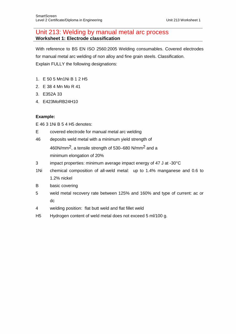
SmartScreen Level 2 Certificate/Diploma in Engineering Unit 213 Worksheet 1
Unit 213: Welding by manual metal arc process Worksheet 1: Electrode classification With reference to BS EN ISO 2560:2005 Welding consumables. Covered electrodes
for manual metal arc welding of non alloy and fine grain steels. Classification.
Explain FULLY the following designations:
1. E 50 5 Mn1Ni B 1 2 H5
2. E 38 4 Mn Mo R 41
3. E352A 33
4. E423MoRB24H10
Example: E 46 3 1Ni B 5 4 H5 denotes:
E covered electrode for manual metal arc welding
46 deposits weld metal with a minimum yield strength of
460N/mm2, a tensile strength of 530–680 N/mm2 and a
minimum elongation of 20%
3 impact properties: minimum average impact energy of 47 J at -30°C
1Ni chemical composition of all-weld metal: up to 1.4% manganese and 0.6 to
1.2% nickel
B basic covering
5 weld metal recovery rate between 125% and 160% and type of current: ac or
dc
4 welding position: flat butt weld and flat fillet weld
H5 Hydrogen content of weld metal does not exceed 5 ml/100 g.
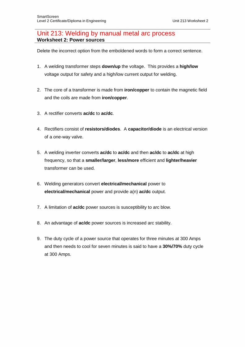
SmartScreen Level 2 Certificate/Diploma in Engineering Unit 213 Worksheet 2
Unit 213: Welding by manual metal arc process Worksheet 2: Power sources
Delete the incorrect option from the emboldened words to form a correct sentence.
1. A welding transformer steps down/up the voltage. This provides a high/lowvoltage output for safety and a high/low current output for welding.
2. The core of a transformer is made from iron/copper to contain the magnetic field
and the coils are made from iron/copper.
3. A rectifier converts ac/dc to ac/dc.
4. Rectifiers consist of resistors/diodes. A capacitor/diode is an electrical version
of a one-way valve.
5. A welding inverter converts ac/dc to ac/dc and then ac/dc to ac/dc at high
frequency, so that a smaller/larger, less/more efficient and lighter/heavier transformer can be used.
6. Welding generators convert electrical/mechanical power to
electrical/mechanical power and provide a(n) ac/dc output.
7. A limitation of ac/dc power sources is susceptibility to arc blow.
8. An advantage of ac/dc power sources is increased arc stability.
9. The duty cycle of a power source that operates for three minutes at 300 Amps
and then needs to cool for seven minutes is said to have a 30%/70% duty cycle
at 300 Amps.
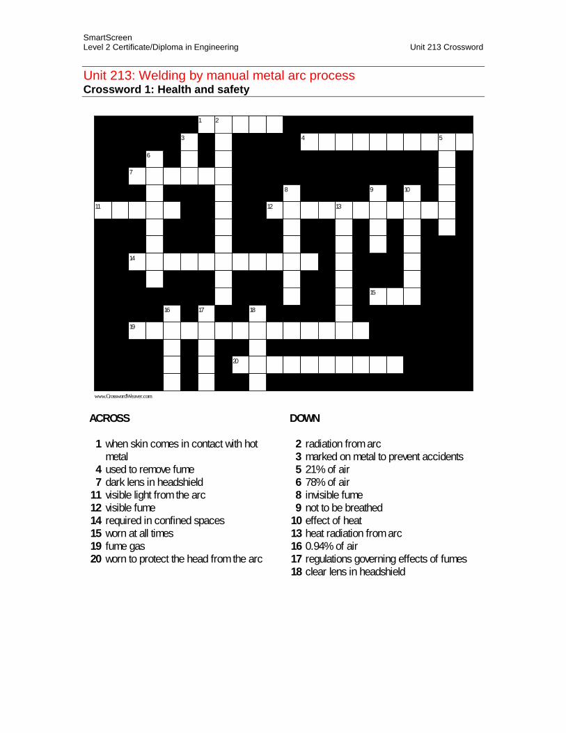
SmartScreen Level 2 Certificate/Diploma in Engineering Unit 213 Crossword
Unit 213: Welding by manual metal arc process Crossword 1: Health and safety
1 2
3 4 5
6
7
8 9 10
11 12 13
14
15
16 17 18
19
20
www.CrosswordWeaver.com
ACROSS
1 when skin comes in contact with hotmetal
4 used to remove fume7 dark lens in headshield
11 visible light from the arc12 visible fume14 required in confined spaces15 worn at all times19 fume gas20 worn to protect the head from the arc
DOWN
2 radiation from arc3 marked on metal to prevent accidents5 21% of air6 78% of air8 invisible fume9 not to be breathed
10 effect of heat13 heat radiation from arc16 0.94% of air17 regulations governing effects of fumes18 clear lens in headshield

Please bring your completed workbook with you when you attend class.
When you have studied this material please contact us to make arrangements for your practical training.