2.4 GHz Spectrum Analyzer Adapter - QSL.net GHz Spectrum Analyzer Adap… · 2.4 GHz Spectrum...
12
2.4 GHz Spectrum Analyzer Adapter Overview This is a updated and slightly more robust version of a 2.4 GHz downconverter which we first talked about in Issue #6. This particular downcoverter will be designed mostly for extending the range of a spectrum analyzer or a frequency counter. The high dynamic range will also allow this converter to be useful in certain electronic warfare applications. The RF input will be able to handle slightly more input power, up to 100 mW (+20 dBm), and will not be bandpass filtered. An optional external bandpass filter can be used to narrow the frequency range of the mixer. The 2.278 GHz local oscillator will be supplied from a stock California Amplifier MMDS downconverter circuit board. The downconverter's die-cast aluminum case and the antenna input N connector will also be used. The theory of operation is simple. Direct RF energy in the range of 2.4 GHz to 2.5 GHz is applied to the RF port on a Mini-Circuits MBA-25MH mixer. The California Amplifier's 2.278 GHz local oscillator signal, slightly underpowered at +5 dBm, will then be applied to the mixer's LO port. The mixer's IF output will be in the VHF frequency range, at around 172 MHz for a 2.45 GHz input. The IF signal will then be low-pass filtered and sent to a Motorola MWA120 wideband amplifier. The MWA120 was chosen for its natural tendency to roll off frequencies above 400 MHz, and also for its fairly low-noise and high third-order intercept capabilites. Standard Mini-Circuits MAR-x series MMICs can be used for post-mixer IF amplification, or even no IF amplification can be used, if so desired. Proper RF and microwave construction techniques will be required to keep the circuit from oscillating or generating a large amount of output spurious signals. Proper 50 ohm termination on all the mixer's ports will also be required for maximum performance. -------------------------------------------------------------------------------------- Frequency Conversions RF Input (MHz) IF Output (MHz) Notes -------------------------------------------------------------------------------------- 2300 22 13 cm Ham Band 2325 47 2350 72 2375 97 2400 122 Part 15 / Ham Band 2425 147 Part 15 / Ham Band 2450 172 Part 15 / Ham Band / Microwave Ovens 2475 197 Part 15 / Ham Band 2500 222 MMDS 2525 247 MMDS 2550 272 MMDS 2575 297 MMDS 2600 322 Pedophiles / MMDS 2650 372 MMDS 2700 422 MMDS -------------------------------------------------------------------------------------- Local Oscillator : 2.278 GHz The optional IF low-pass filter rolls off gain above 250 MHz. -------------------------------------------------------------------------------------- 27
Transcript of 2.4 GHz Spectrum Analyzer Adapter - QSL.net GHz Spectrum Analyzer Adap… · 2.4 GHz Spectrum...
2.4 GHz Spectrum Analyzer Adapter
Overview
This is a updated and slightly more robust version of a 2.4 GHz downconverter which we first talkedabout in Issue #6. This particular downcoverter will be designed mostly for extending the range of aspectrum analyzer or a frequency counter. The high dynamic range will also allow this converter tobe useful in certain electronic warfare applications.
The RF input will be able to handle slightly more input power, up to 100 mW (+20 dBm), and will notbe bandpass filtered. An optional external bandpass filter can be used to narrow the frequencyrange of the mixer. The 2.278 GHz local oscillator will be supplied from a stock California AmplifierMMDS downconverter circuit board. The downconverter's die−cast aluminum case and the antennainput N connector will also be used.
The theory of operation is simple. Direct RF energy in the range of 2.4 GHz to 2.5 GHz is applied tothe RF port on a Mini−Circuits MBA−25MH mixer. The California Amplifier's 2.278 GHz localoscillator signal, slightly underpowered at +5 dBm, will then be applied to the mixer's LO port. Themixer's IF output will be in the VHF frequency range, at around 172 MHz for a 2.45 GHz input. TheIF signal will then be low−pass filtered and sent to a Motorola MWA120 wideband amplifier. TheMWA120 was chosen for its natural tendency to roll off frequencies above 400 MHz, and also for itsfairly low−noise and high third−order intercept capabilites. Standard Mini−Circuits MAR−x seriesMMICs can be used for post−mixer IF amplification, or even no IF amplification can be used, if sodesired.
Proper RF and microwave construction techniques will be required to keep the circuit fromoscillating or generating a large amount of output spurious signals. Proper 50 ohm termination onall the mixer's ports will also be required for maximum performance.
−−−−−−−−−−−−−−−−−−−−−−−−−−−−−−−−−−−−−−−−−−−−−−−−−−−−−−−−−−−−−−−−−−−−−−−−−−−−−−−−−−−−−−Frequency Conversions
RF Input (MHz) IF Output (MHz) Notes−−−−−−−−−−−−−−−−−−−−−−−−−−−−−−−−−−−−−−−−−−−−−−−−−−−−−−−−−−−−−−−−−−−−−−−−−−−−−−−−−−−−−−2300 22 13 cm Ham Band2325 472350 722375 972400 122 Part 15 / Ham Band2425 147 Part 15 / Ham Band2450 172 Part 15 / Ham Band / Microwave Ovens2475 197 Part 15 / Ham Band2500 222 MMDS 2525 247 MMDS2550 272 MMDS2575 297 MMDS2600 322 Pedophiles / MMDS2650 372 MMDS2700 422 MMDS−−−−−−−−−−−−−−−−−−−−−−−−−−−−−−−−−−−−−−−−−−−−−−−−−−−−−−−−−−−−−−−−−−−−−−−−−−−−−−−−−−−−−−Local Oscillator : 2.278 GHz
The optional IF low−pass filter rolls off gain above 250 MHz.−−−−−−−−−−−−−−−−−−−−−−−−−−−−−−−−−−−−−−−−−−−−−−−−−−−−−−−−−−−−−−−−−−−−−−−−−−−−−−−−−−−−−−
27

Construction Notes & Pictures
Parts overview for the ammo box we'll mount the converter in.
To the left is a filtered IEC AC line socket, a panel−mount fuse holder, a SPDT switch with a rubberboot cover, and a green neon power indicator lamp. In the middle are the panel−mount BNC and NRF connectors which will be used to connect up to the converter. On the right is a surplus +15 VDC"wall wart" power supply secured to a small piece of right−angle aluminum. Solder the 120 VACinput to the wall wart directly to the prongs and cover them with heatshrink tubing.
28

Assemble the converter PC board as shown above.
The mixer's local oscillator input is on the lower−right. The RF input is via the attenuator pad goingoff to the left. The IF output goes up into the MWA120 amplifier. A 78M12 regulates the incomingwall wart voltage.
The jumper wire is the +12 VDC line for the stock local oscillator section in the California Amplifierdownconveter.
29
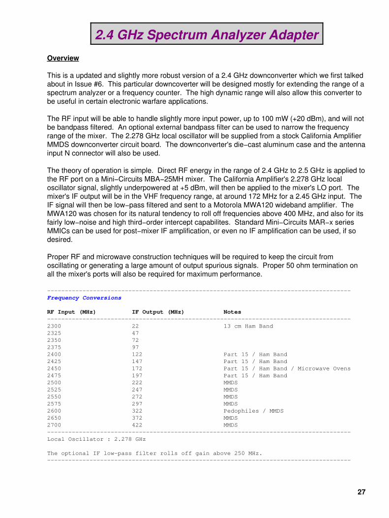
Alternate view.
The large black things in series with the voltage lines are surface−mount ferrite beads. The inputfilter capacitor to the 78M12 is 47 µF and the output capacitor is a 10 µF tantalum.
30
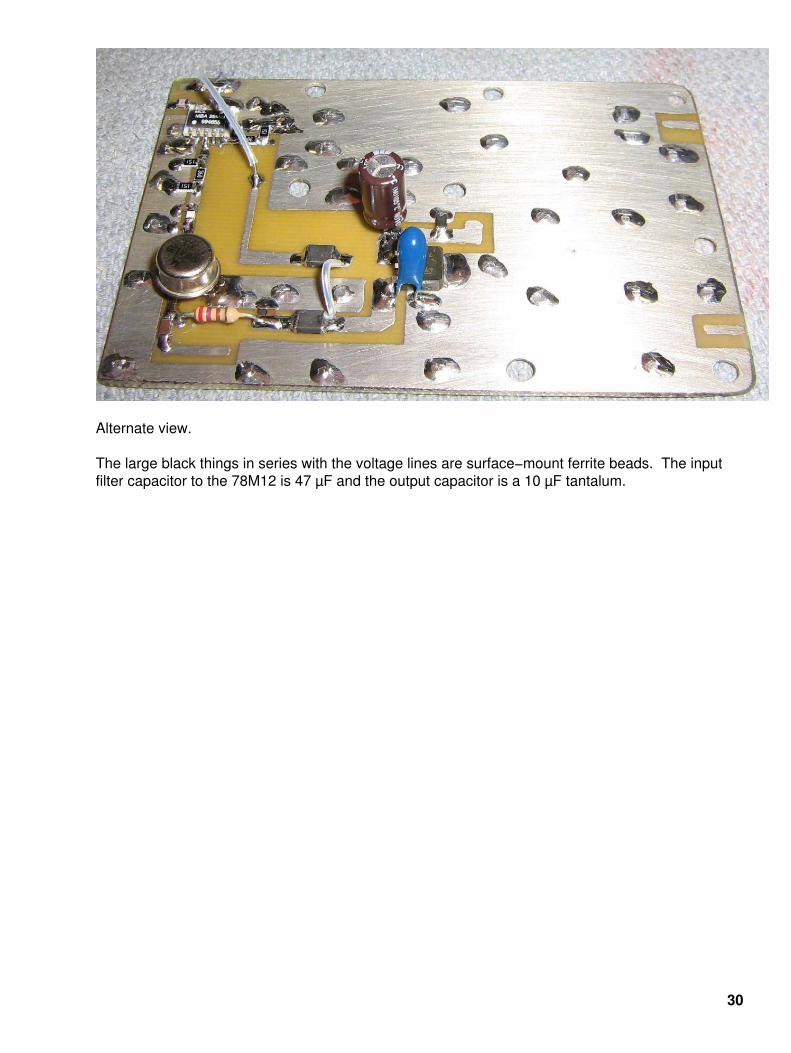
Modified California Amplifier downconveter.
The red arrow points to the downconveter's local oscillator output, after a stripline bandpassfilter. The 2.278 GHz signal is at around +5 dBm (3.1 mW). This is a little low and conversion losswill suffer. The mixer is designed to see at least +10 dBm (or even +7 dBm) on its LO port.
31

Close up view.
You'll have to scrape a little bit of solder mask off the output stripline from the bandpass filter, asshown on the lower−right. Also note the thin stripline trace off to the far−right of the PC board. Thisis the +12 VDC line for powering the 2.278 GHz oscillator circuit.
32

Install the new PC board, being sure it is both mechanically and electrical stable.
You can also install the RF connectors at this point and small pieces of coax to connect up to theconnectors. For this particular project, a N connector will be used on the RF input and a BNCconnector on the IF output.
Small zero−ohm jumpers connect the downconveter's local oscillator output to the new PCboard. The two zero−ohm jumpers to the left of the MWA120 in the above photo are for mechanicalstablity.
33
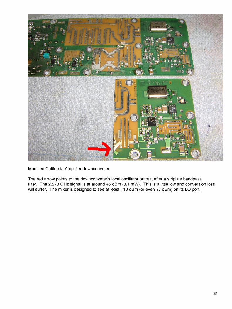
Mount for the +15 VDC wall wart power supply.
Secure the power supply itself with small pieces of art foam and zip ties.
The incoming AC power lines are soldered directly to the wall wart's prongs, with the extra set ofwires to power a neon power indicator lamp.
34
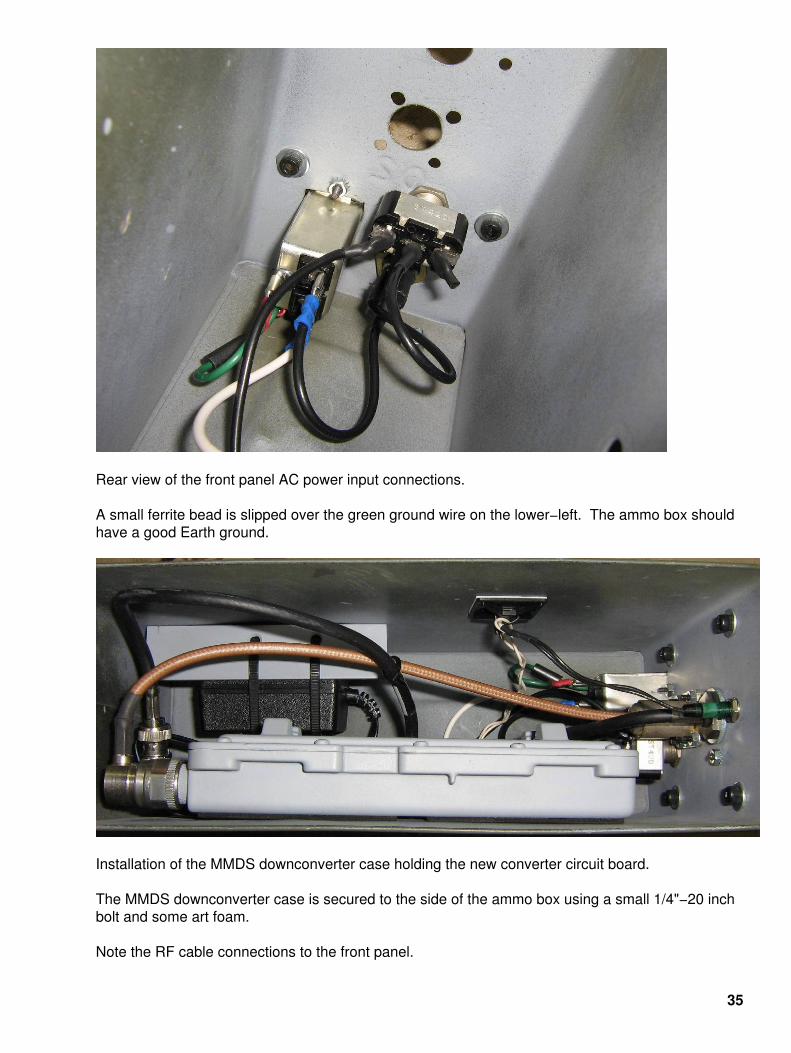
Rear view of the front panel AC power input connections.
A small ferrite bead is slipped over the green ground wire on the lower−left. The ammo box shouldhave a good Earth ground.
Installation of the MMDS downconverter case holding the new converter circuit board.
The MMDS downconverter case is secured to the side of the ammo box using a small 1/4"−20 inchbolt and some art foam.
Note the RF cable connections to the front panel.
35
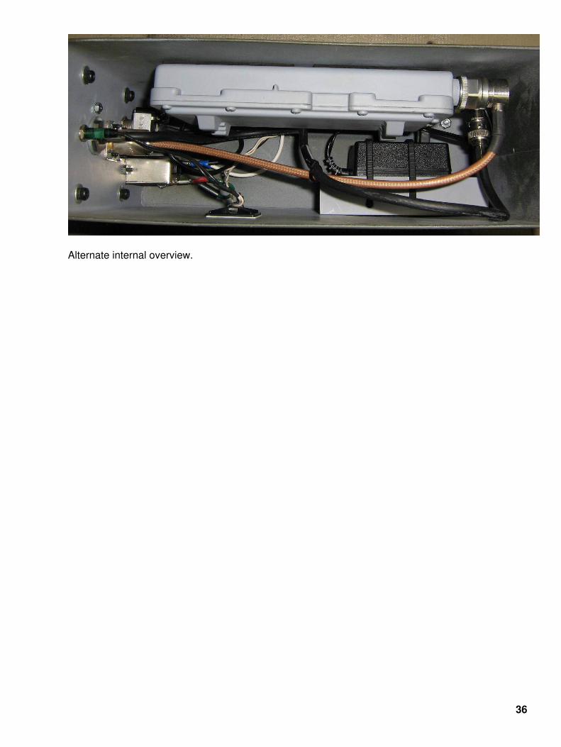
Alternate internal overview.
36

Completed front panel overview.
There are dust caps installed on the input N connector and the output BNC connector.
Brass drawer handles protect the front panel and the RF connectors from any abuse.
The green neon lamp in the upper−center is a 120 VAC power indicator.
37

38