215 MINI BIKE - GoKarts USA 215 Mini Bike is equipped with a lazer cut, precision welded, heavy duty...
22
215 MINI BIKE OWNER GUIDE By GOKARTS USA
Transcript of 215 MINI BIKE - GoKarts USA 215 Mini Bike is equipped with a lazer cut, precision welded, heavy duty...

215 MINI BIKE
OWNER GUIDE
By
GOKARTS USA
1
CONTENTS
SAFETY INFORMATION ................................................................................... 2
AMERICAN RACER MINI BIKE........................................................................ 3
UNPACK AND SEPARATE PARTS ................................................................... 4
Parts List: ........................................................................................................... 4
PAINT ................................................................................................................ 5
ASSEMBLY INSTRUCTIONS ............................................................................ 6
FORK ............................................................................................................. 6
WHEELS ....................................................................................................... 7
TIRES ............................................................................................................ 8
SPROCKET/DRUM ...................................................................................... 9
BRAKE ........................................................................................................ 10
REAR WHEEL ............................................................................................ 10
REAR AXLE ............................................................................................... 11
ENGINE ....................................................................................................... 12
TORQUE CONVERTER ............................................................................ 14
THROTTLE CONTROL (stock carburetor) ................................................ 15
BRAKE LEVER .......................................................................................... 17
BRAKE CABLE .......................................................................................... 17
ADJUST BRAKE ............................................................................................ 18
KICKSTAND .................................................................................................. 18
OIL SERVICE ................................................................................................. 18
TEST RUN....................................................................................................... 19
Avoid run-away bike .................................................................................... 19
FEATURES ..................................................................................................... 20
PERFORMANCE PARTS ............................................................................... 21
Boost your Honda, Titan or Predator up to 26hp ......................................... 21
HIGH FLOW EXHAUST ..................................................................... 21
STAGE 1 KIT ......................................................................................... 21

2
SAFETY INFORMATION
POWERSPORTS Products MUST NOT BE OPERATED ON THE
STREET. They are FOR USE ON A CLOSED COURSE ONLY.
DEATH OR INJURY CAN OCCUR PERSONS UNDER THE AGE OF 16 must be SUPERVISED by
a competent adult.
MECHANIC REQUIRED
Minibikes, Gokarts, ATVs etc. MUST BE CHECKED, MAINTAINED AND/OR ADJUSTED BY CUSTOMER’S
MECHANIC PRIOR TO EACH USE.
Even if your mini bike kit is new or assembled, it must still be checked, adjusted and serviced by a qualified mechanic
EACH TIME prior to operation. All systems must be checked and adjusted by YOUR qualified Mechanic including Drive
Train, Engine and Fuel system, Throttle Control, Brakes, Wheels, Tires and all other systems.
DO NOT OPERATE THIS MINIBIKE UNTIL MECHANIC SETUP
IS PERFORMED. WARNING, DEATH OR INJURY CAN OCCUR
GOKARTS AND MINIBIKES CAN BE DANGEROUS TO OPERATE. INJURY AND DEATH CAN RESULT FROM
IMPROPER ASSEMBLY, MAINTENANCE and/or operation.
Customer assumes all risk associated with assembling, maintaining, building and operating any minibike or go kart
kit. Customer agrees to hold harmless go karts USA and its associates, affiliates and parent companies.
Customer responsible for engine and drive train installation,
adjustment, fabrication, modification, repair and maintenance on any go kart or minibike.
Go kart and Mini Bike kits must be assembled by a qualified mechanic for safety reasons as well as proper operation.
These are parts only. The Customer is responsible for final
design and building of the minibike and installing the Drive train. Customer assumes all risk associated with assembling
and operating any minibike, go kart or any vehicle the customer builds using these parts. Customers should

3
complete a rider safety course prior to the operation of any power sport product.
NO WARRANTY
No warranty on go karts or mini bikes. They are not returnable for any reason and no refunds will be issued.
Customer is responsible for painting and assembly of kit. For safety reasons as well as proper operation, we strongly
recommend that kits are assembled and/or inspected by a qualified mechanic or persons with appropriate mechanical
expertise prior to operation. We cannot refund or exchange your kit if you cannot perform these functions or refuse to
let a shop do it for you
AMERICAN RACER MINI BIKE
The American Racer 215 Mini Bike is sold fully assembled.
The 215 is also available as a kit.

4
UNPACK AND SEPARATE PARTS
215 Frame and Fork
PARTS LIST:
L1065-3020 Front Wheel, 8"
L1065-3021 Front Wheel Bearing L1065-3052 Front Tire 480 x 8
L1065-3053 Front Tube 480 x 8 L1065-3012 Front Wheel Spacers, (2)
L1065-3013 Front 5/8 Axle L1065-3014 Front 5/8 Nut for Axle
L1065-3017 Kickstand L1065-3059 Long Seat
L1065-3020 Rear Wheel, 8" w/(2) Bearings L1065-3021 Rear Wheel Bearing
L1065-3052 Rear Tire 480/400 x 8
L1065-3053 Rear Tube 480/400 x 8 L1065-3025 Rear 5/8 Axle
L1065-3026 Rear 5/8 Nut for Axle L1065-3027 Rear Drum/Sprocket 40/41 54T
L1065-3028 5" Drum Brake Assy L1065-3030 5" Brake Anchor / Spacer
L1065-3054 Throttle Control & Grips 1" L1065-3035 Throttle Cable
L1065-3036 Throttle Wire Stop L1065-3037 Brake Lever
L1065-3038 Brake Cable L1065-3039 #40 Chain
L2065-3039 #40 Master Link
Order replacement parts online at gokartsusa.com

5
PAINT
❍ Thoroughly clean the Fork, and Frame, making sure to
remove the rust proofing oil.
❍ The 5/16-18 x 6" Bolt connects the Fork to the Frame. If
you wish, you may paint the head of the bolt, but the
threaded portion should be left unpainted.
❍ Allow the paint to dry thoroughly before any assembly.

6
ASSEMBLY INSTRUCTIONS
FORK
• Place your frame on a stand.
• Align the Fork onto the Frame Neck. Slide the Fork
Bolt down into the Neck.
• Fasten the nut at the bottom until snug, and then
back it off slightly to allow the fork to move freely
back and forth.
• Full Size for an Adult up to 6’5”
• Handlebars tilt forward for more room for your knees
• Large Foot Pegs
• 5 Degree Engine Mount
• Cut-away for Torque Converter
• Heavy Duty Axle with Chain Adjust

7
WHEELS
Each wheel has two halves, marked 8020 and 8021.
• Drill out the three sprocket mounting holes on the
8020 wheel half for the rear wheel. Drill from the inner
side of the wheel. You will see channels for the holes.
Your holes will pop through the bumps on the outer
side of the wheel. Do not drill the 8021 wheel half.
• Do not drill these holes on the front wheel.
• Inflate the innertube a small amount for easier
installation. Insert the innertube into the tire. Align
both wheel halves into tire, being careful not to pinch
the innertube. Bolt the wheel together.
• Do this for both wheels. See details below.

8
TIRES
❍ Insert Innertube into the Tire so that it is snug and resting
completely within the tire. Inflate the Innertube with just
enough air to remove the folds from the tube (1 or 2 psi).
❍ Mount the Tire onto a Wheel set, as follows:
❍ Insert one Wheel half into each side of the Tire and over the
Innertube. CAUTION: Do not pinch the tube between the wheel
halves.
❍ Carefully position both Wheel halves so that the half-moon cuts
on the inside rims form a circular opening around the valve
stem of the innertube.
❍ Secure the Wheel halves together using three of the 5/16 18 x
3" Bolts and three of the 5/16-18 Locknuts. For now, tighten
the Locknuts only finger tight. Do not inflate the tire yet.
❍ Insert the threaded Axle into the wheel assembly through the
5/8" bearings. Doing so aligns the wheel halves.
❍ Carefully tighten each nut in sequence. Torque down each nut
tightly, but do not over torque. If you have a torque wrench,
which is suggested, tighten each nut to 5 ft-lbs.
CAUTION: If you use a source of compressed air to inflate the
tires, use eye protection and a tire cage during inflation. A
simple bicycle tire hand-pump is sufficient to provide adequate
inflation.
❍ Inflate the tire to 15 psi and make sure it is seated properly on
the wheel (tire bead flush with wheel rim and the wheel halves
showing no gap at the center line).

9
SPROCKET/DRUM
Your 215 Mini Bike is equipped with a lazer cut, precision
welded, heavy duty Sprocket/Brake Drum to ensure
smooth, reliable operation of the drivetrain.
• Bolt the sprocket/drum onto the rear wheel using
three additional bolts into the holes you
previously drilled on the 8020 wheel half. The
bolts will go through from the inside of the wheel.
Fasten the nuts and tighten in a pattern to make
sure the sprocket is centered and true
• Note: The picture above shows the brake cable
anchor used on the Little BadAss Mini Chopper.
The 215 has an integrated brake cable anchor and
does not come with this anchor shown
10
BRAKE
• Insert the two bolts of the brake ancher/spacer
through the brake plate, then place the assembly
into the drum. Slide the Axle through to hold the
wheel and brake assembly in place.
• Spin the wheel and check the sprocket for true and
proper operation. If the sprocket is installed
correctly, you should not see any wobble in the
sprocket when the wheel spins.
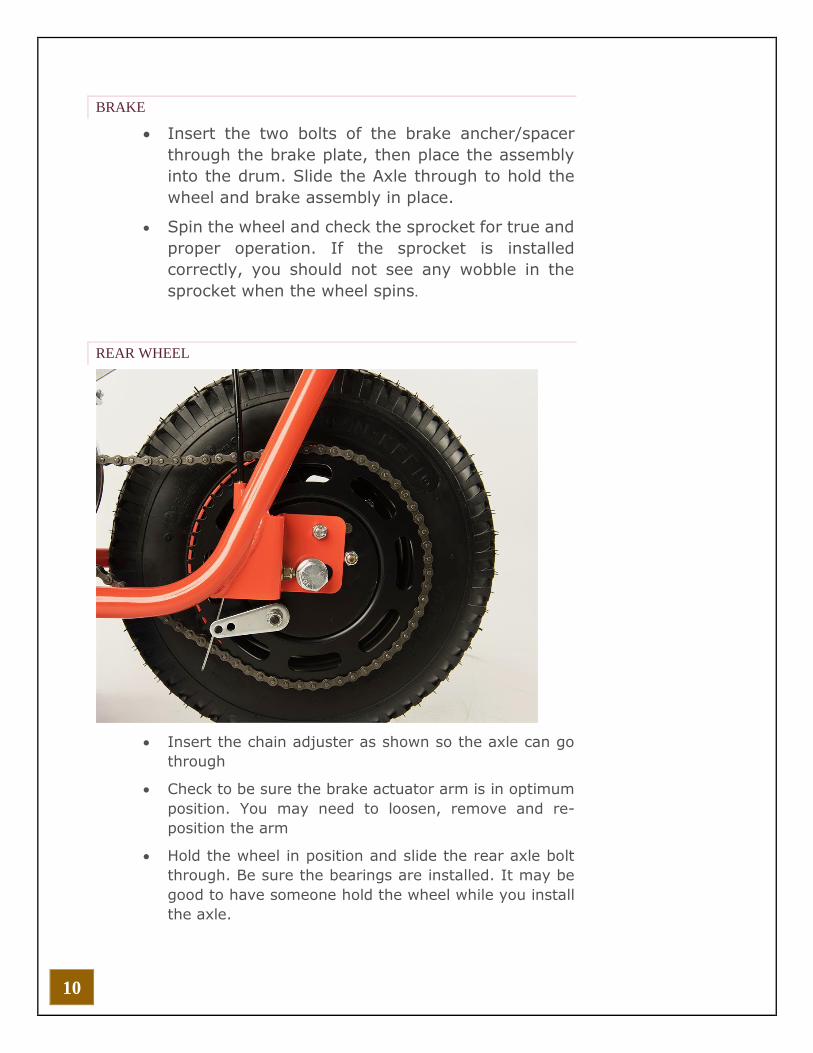
REAR WHEEL
• Insert the chain adjuster as shown so the axle can go
through
• Check to be sure the brake actuator arm is in optimum
position. You may need to loosen, remove and re-
position the arm
• Hold the wheel in position and slide the rear axle bolt
through. Be sure the bearings are installed. It may be
good to have someone hold the wheel while you install
the axle.

11
REAR AXLE
• Axle and Nut
• Chain Adjusters (2)
• Note: There are only two chain adjusters needed,
shown installed on the outer portions of the axle
below. two extra, unused chain adjusters are
shown hanging loose on the axle. Please disregard.
• Brake Anchor/Spacer with two bolts. One bolt
fastens to the frame, the other only fastens to the
brake plate

12
ENGINE
215 Frame will accept these engines
• Honda GX120/160/200
• Titan TX200
• Predator 212
Titan TX200 engine has the side mounted fuel neck for
easy fueling.
Honda Engines will fit, we recommend using a low profile
gas cap
Predator 212 will fit, but the stock gas cap is large,
making re-fueling a bit difficult.
• NOTE: Engine, engine mounting hardware,
clutch and clutch installation hardware are not
provided and must be obtained. Seek the
recommendation of your engine manufacturer
about an engine suitable for your rider. Be sure
to obtain all appropriate installation hardware
and take note of any special instructions and
recommendations regarding installation of your
engine and clutch.

13
• Place the Engine on the Frame’s engine
mounting plate, aligning the engine’s mounting
holes with the slots in the Frame’s mounting
plate.
• Insert the engine mounting bolts down into the
engine’s mounting holes until they extend
through the bottom of the Frame’s mounting
plate slots.
• Carefully slide the engine as far to the rear of
the mounting plate as possible and then place
washers and/ or Locknuts onto the bolts. At this
time, hand-tighten only.
• NOTE: The engine must remain in this
temporary pushed-to-the-rear position until
after you have installed the chain.

14
TORQUE CONVERTER
We recommend installing the Torque Converter onto the
engine prior to installing the engine on the bike.
• Please use the link below to download the GTC TC2
Installation Instructions
• http://gtcmanufacturing.com/tc2installation.pdf
• There is a cut-away on the motor plate for the Torque
Converter. The torque converter triples the climbing
power and increases top end.
• The bike can also support a Centrifugal Clutch. You
will need a chain tensioner, and longer chain. This is
the preferred configuration for racers who need more
precise speed control without the hesitation of a
torque converter.
• Shown with the stock cover.
• Cast Aluminum Open Primary Cover also available

15
THROTTLE CONTROL (STOCK CARBURETOR)
• Measure the conduit to the desired length and cut to
fit. The conduit should be about 6” shorter than the
cable. Don’t cut too short, leave a little extra room.
You can always cut a little more, but you cannot add
any length.
• Make sure you use a sharp wire cutter when cutting
the cable. A clean, quick cut will prevent the cable
from fraying. You are going to thread the cable
through the barrel connector at the carburetor. If
you fray the cable, cut off a few of the frayed strands
• Install the throttle cable into the twist grip control so
that the barrel end slips into the notch.
• Install the Throttle Control onto the handlebar. (on
the right when sitting on the bike). Using a Philips
screw driver, gently tighten each screw a little at a
time. Don’t over tighten the screws. Too tight, and
your control will bind when you twist it. Too loose,
and it will move when operated.

16
• Route the Throttle Cable and Housing down the Fork
and right of the Frame toward the carburetor, using
conduit clips to secure the Cable and Housing to the
Fork and frame as you go. Go past the carburetor,
then loop the cable back to the carb.
• Remove the air cleaner assembly from the
carburetor by removing the nut on top.
• Loosen the nut that secures the manual throttle lever
so that the lever can move freely.
• You will see an L bracket. Fasten the conduit to this
bracket to hold it place. Loop the cable to come in
from the back.
• You will see a barrel connector at the throttle lever.
Loosen the screw, thread the cable into the barrel
connector, then tighten the screw. Be sure the cable
is pulled through the barrel connector until snug.
• You will likely have to re-adjust this once you start
and test the engine.
• Re-Install the air cleaner assembly.
• Note: The throttle mechanism will appear to not be
operating when the engine is not running. The
engine must be running for the throttle to operate
• See more full information for throttle linkage here
• https://gokartsusa.com/pdf/Honda-GX-Throttle-
Linkage.pdf
• Cable Installation on Stock Carburetor (Summary)
Remove the Air-Cleaner assembly so you can see the Throttle
Control Mechanism. Loosen the nut that secures the manual
throttle lever so that the lever can move freely. Locate the
conduit bracket on the engine. and fasten the end of the
conduit with the bracket. Thread the cable into the Wire Stop
connector on the engine. Tighten the screw on the Wire Stop

17
BRAKE LEVER
❍ Loosen both clamp screws on the Brake Lever and install
it onto the Frame’s left handlebar about 4" from the end
with the steel ball end of the Lever pointing left and
forward.
❍ Secure the Brake Lever into position by tightening the
mounting collar screws.
CAUTION: Prior to any operation, be sure to adjust the position
of the Brake Lever so that it is readily available to and easily
accessed and operated by the intended rider.
BRAKE CABLE
❍ Locate the Brake Cable & Conduit Assembly.
❍ Seat the barrel end of the Brake Cable into the hole in the
Brake Lever on the left handlebar and rotate the Cable so that
the barrel end fits into the slot in the brake adjuster housing.
❍ Slide the Housing up over the cable until it fits into the
opening in the Brake Lever.
❍ Route the Brake Cable and Housing down the Fork and left of
the Frame toward the brake, using three Conduit Clips to secure
the Cable and Housing to the Fork and frame as you go.
IMPORTANT: Cable and Housing should be routed and secured
to the inner surfaces of the fork and frame. Avoid sharp bends.
Also, make sure that your routing allows the fork to move freely
from side to side without binding or pinching.
SECURE BRAKE CABLE TO BRAKE
❍ Install the cable to the brake actuator arm using the brake
cable barrel connector

18
ADJUST BRAKE
When adjusted properly, the brake should fully engage and lock
a spinning rear wheel, well before the depressed brake lever
comes into contact with the handlebar
❍ Adjust the Brake by loosening the screw on the brake barrel
connector and tightening up the excess slack in the cable.
❍ Cut off excess Brake Cable which remains past the end of the
Wire Swivel.
NOTE: You may choose to leave a small length necessary for
ease of adjustment. Make certain, however, that excess cable
remaining will not interfere with any other vehicle operation and
will not come into contact with the rider
KICKSTAND
• Measure, cut to fit
• Install onto frame bracket
OIL SERVICE
• Add just over a half of a quart. 10W30 oil recommended.
• Synthetic ok
• Check the dipstick
• You should see oil at the bottom of the threads of the oil
filler cap
• For high performance, high heat operation, change oil
frequently
• Titan has a low oil sensor, engine will not start

19
TEST RUN
AVOID RUN-AWAY BIKE.
WARNING
Until you properly adjust your throttle, the first few times
you start your bike, the engine may accelerate to full
throttle. We strongly recommend a two person start. One
person to stand in front of the bike to hold it. The other
person to operate the pull start, throttle control and kill
switch.
As part of road test, check and adjust the following:
Add Engine Oil, Fuel
Adjust Engine Idle
Adjust Throttle Cable
Adjust Throttle Control
Adjust Brake Cable
Adjust Chain Tension
Set Tire pressure 12-15lbs
These items must be checked BEFORE EVERY RIDE

20
FEATURES
1" Heavy Duty Frame
5° Engine Mount with Cut-Away for TC2 Torque Converter
Front and Rear Fender Mounts
Heavy Duty Rear Axle Mount
Kickstand Mount
Fork Assembly
8" Aluminum Wheels
Premium Tires and Inner tubes
5" Heavy Duty LBA Drum Brake
Integrated #40/41 54 Tooth Sprocket
Chain Tension Adjusters
Premium 40/41 Chain
6.5hp engine
TC2 Torque Converter

21
PERFORMANCE PARTS
BOOST YOUR HONDA, TITAN OR PREDATOR UP TO 26HP...
HIGH FLOW EXHAUST
The stock exhaust is also very restrictive. A favorite among
Kart Racers, the RLV Header Pipe and Silencer will give you a
substantial boost in power and that great sound for a low
cost. You will need the Locking Collar to fasten the silencer.
Also available for use on both Karts and Minibikes are the
Fatty Exhaust and Stinger Exhausts Headers for Maximum
Power and Awesome Sound
STAGE 1 KIT
Stock Carb: The Stage 1 Kit, Stock Carb is an inexpensive,
easy bolt-on Upgrade to the Intake and Exhaust. Also
available is the Genuine K&N Stage 1 Kit. Mikuni Carb: For
Top Power see the Mikuni Stage 1 Kit with Fatty or Mikuni
Stage 1 Kit with Stinger. This carb upgrade really wakes up
the responsiveness of the engine and, as an added bonus,
allows you to remove the stock throttle linkage mechanism
and replace it with one simple throttle Cable connection.
Mikuni STAGE 1 INSTALL GUIDE
CARB JETS: Upgrading the Intake and Exhaust usually
requires re-jetting the Carburetor. If you have to play with
your choke to get your engine to run properly, you need to
adjust the Carb Main Jet. For the Stock Carb see Honda Main
Jets. The .035 Main Jet seems to work best but you may want
to try .034, .035 and .036 to see which works best for your
engine. For our Mikuni Carbs see Mikuni Main Jets 120-140
for Curved Intake, 170-190 for the Inverted Intake. Open the
Float Bowl, unscrew the jet and put in a larger size. see
Mikuni Tuning Guide