210 Arterials and Collectors · Topic #625-000-002 FDOT Design Manual 210 – Arterials and...
50
Topic #625-000-002 FDOT Design Manual 210 – Arterials and Collectors 210 Arterials and Collectors 210.1 General The design criteria presented in this chapter apply to new construction and reconstruction projects on arterials and collectors on the State Highway System. Roadways not on the State Highway System which are impacted by these new construction and reconstruction projects should also be designed in accordance with this manual; however, districts may allow the use of the Manual of Uniform Minimum Standards for Design, Construction and Maintenance for Streets and Highways (commonly known as the "Florida Greenbook"). This chapter also provides minimum criteria to be used with Resurfacing, Restoration, and Rehabilitation (RRR) projects as described in FDM 210.1.1. Facilities on the Strategic Intermodal System (SIS) are subject to special standards and criteria for number of lanes, design speed, access, and level of service. Design all SIS and Emerging SIS Highway Intermodal Connectors in accordance with the SIS criteria contained in this manual. With approval by the District Design Engineer, the Florida Greenbook may be used on SIS facilities that are not on the State Highway System. Modification for Non-Conventional Projects: Delete the last sentence of the above paragraph and see RFP for requirements. Many design criteria are related to design speed; e.g., vertical and horizontal geometry, sight distance. The minimum design values are closely related to traffic safety and require an approved Design Exception or Design Variation when they are not met. See FDM 201 for information on Design Speed. See FDM 122 for information on Design Exceptions and Design Variations. Example roadway typical sections are included in the exhibits in FDM 306. Criteria regarding lanes, medians, and shoulders for bridges are illustrated in FDM 260.1.1. Subsequent sections of this chapter contain specific information and criteria regarding these and other typical section elements, as well as geometric features. Modification for Non-Conventional Projects: Delete the last sentence of the above paragraph and see RFP for requirements. 1 January 1, 2018
Transcript of 210 Arterials and Collectors · Topic #625-000-002 FDOT Design Manual 210 – Arterials and...
Topic #625-000-002 FDOT Design Manual
210 – Arterials and Collectors
210 Arterials and Collectors
210.1 General
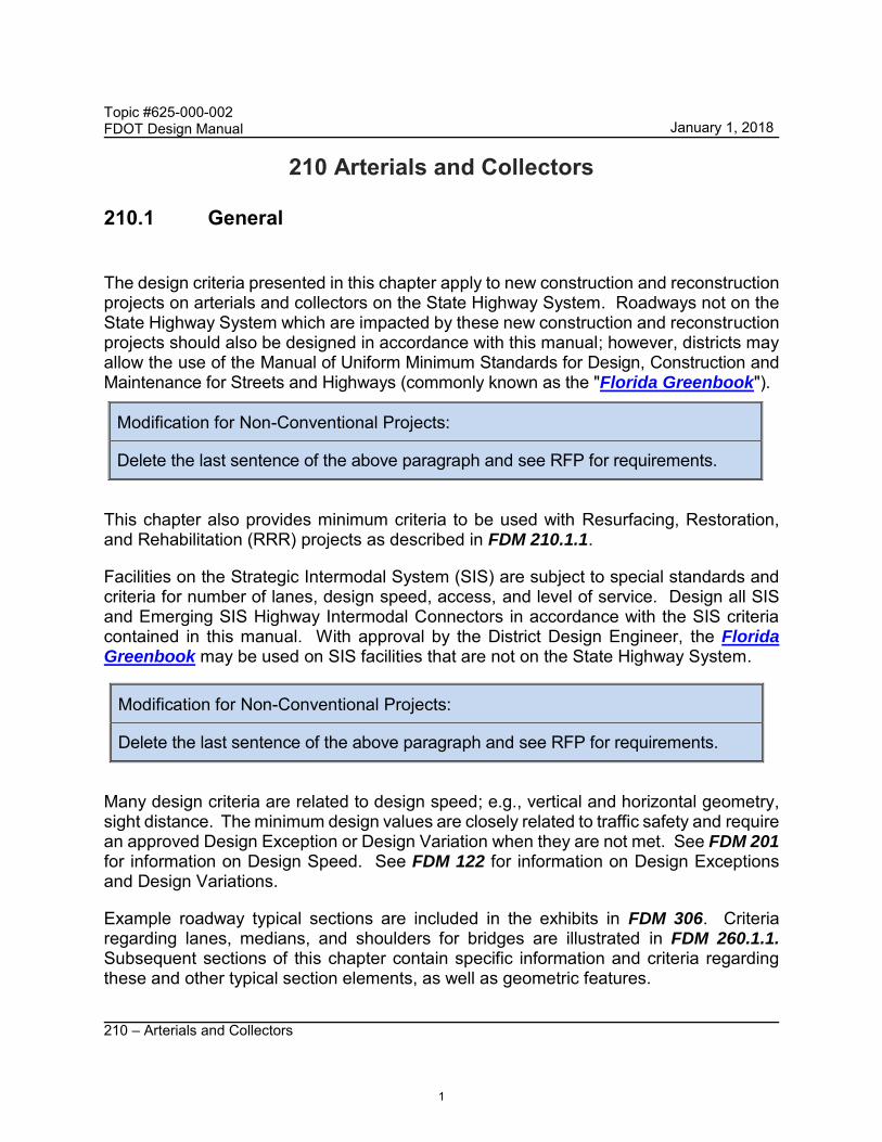
The design criteria presented in this chapter apply to new construction and reconstruction projects on arterials and collectors on the State Highway System. Roadways not on the State Highway System which are impacted by these new construction and reconstruction projects should also be designed in accordance with this manual; however, districts may allow the use of the Manual of Uniform Minimum Standards for Design, Construction and Maintenance for Streets and Highways (commonly known as the "Florida Greenbook").
This chapter also provides minimum criteria to be used with Resurfacing, Restoration, and Rehabilitation (RRR) projects as described in FDM 210.1.1.
Facilities on the Strategic Intermodal System (SIS) are subject to special standards and criteria for number of lanes, design speed, access, and level of service. Design all SIS and Emerging SIS Highway Intermodal Connectors in accordance with the SIS criteria contained in this manual. With approval by the District Design Engineer, the FloridaGreenbook may be used on SIS facilities that are not on the State Highway System.
Modification for Non-Conventional Projects:
Delete the last sentence of the above paragraph and see RFP for requirements.
Many design criteria are related to design speed; e.g., vertical and horizontal geometry, sight distance. The minimum design values are closely related to traffic safety and require an approved Design Exception or Design Variation when they are not met. See FDM 201 for information on Design Speed. See FDM 122 for information on Design Exceptions and Design Variations.
Example roadway typical sections are included in the exhibits in FDM 306. Criteria regarding lanes, medians, and shoulders for bridges are illustrated in FDM 260.1.1. Subsequent sections of this chapter contain specific information and criteria regarding these and other typical section elements, as well as geometric features.
Modification for Non-Conventional Projects:
Delete the last sentence of the above paragraph and see RFP for requirements.
1
January 1, 2018
Topic #625-000-002 FDOT Design Manual
210 – Arterials and Collectors
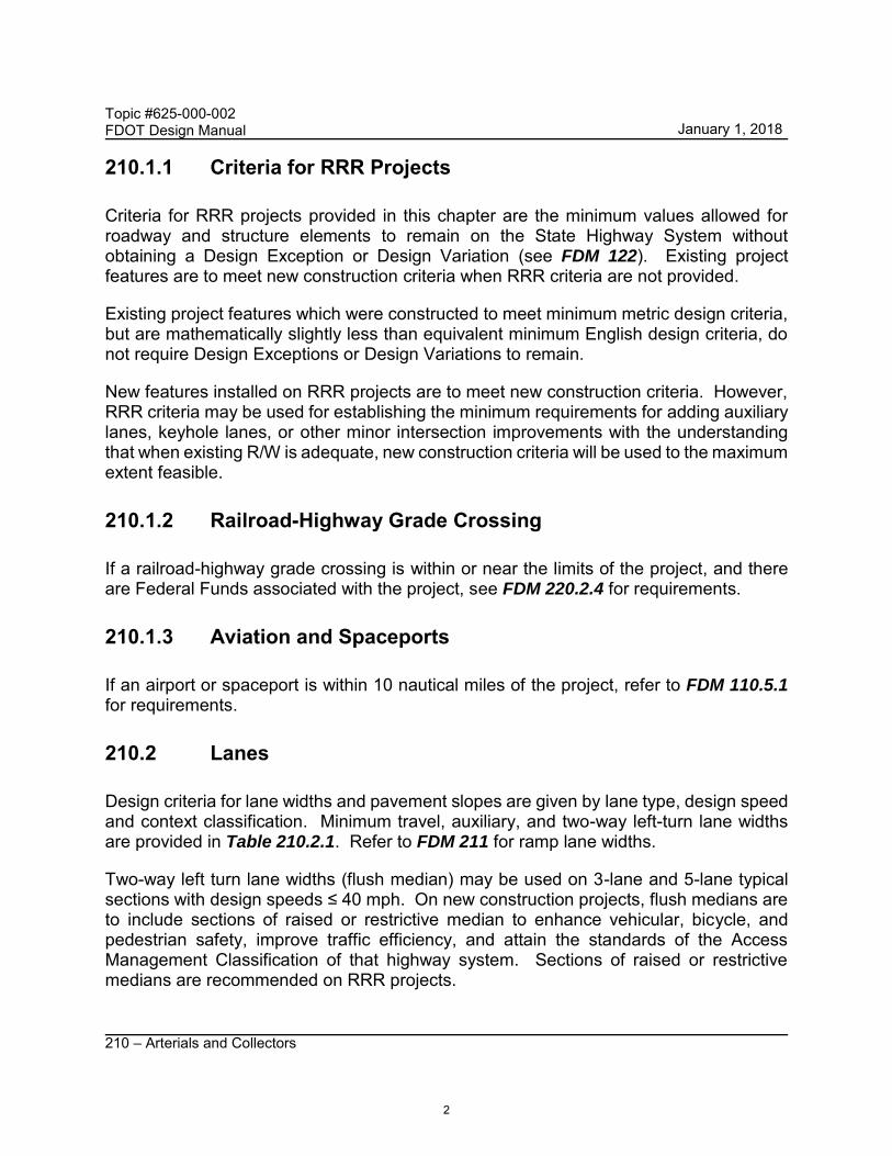
210.1.1 Criteria for RRR Projects
Criteria for RRR projects provided in this chapter are the minimum values allowed for roadway and structure elements to remain on the State Highway System without obtaining a Design Exception or Design Variation (see FDM 122). Existing project features are to meet new construction criteria when RRR criteria are not provided.
Existing project features which were constructed to meet minimum metric design criteria, but are mathematically slightly less than equivalent minimum English design criteria, do not require Design Exceptions or Design Variations to remain.
New features installed on RRR projects are to meet new construction criteria. However, RRR criteria may be used for establishing the minimum requirements for adding auxiliary lanes, keyhole lanes, or other minor intersection improvements with the understanding that when existing R/W is adequate, new construction criteria will be used to the maximum extent feasible.
210.1.2 Railroad-Highway Grade Crossing
If a railroad-highway grade crossing is within or near the limits of the project, and there are Federal Funds associated with the project, see FDM 220.2.4 for requirements.
210.1.3 Aviation and Spaceports
If an airport or spaceport is within 10 nautical miles of the project, refer to FDM 110.5.1 for requirements.
210.2 Lanes
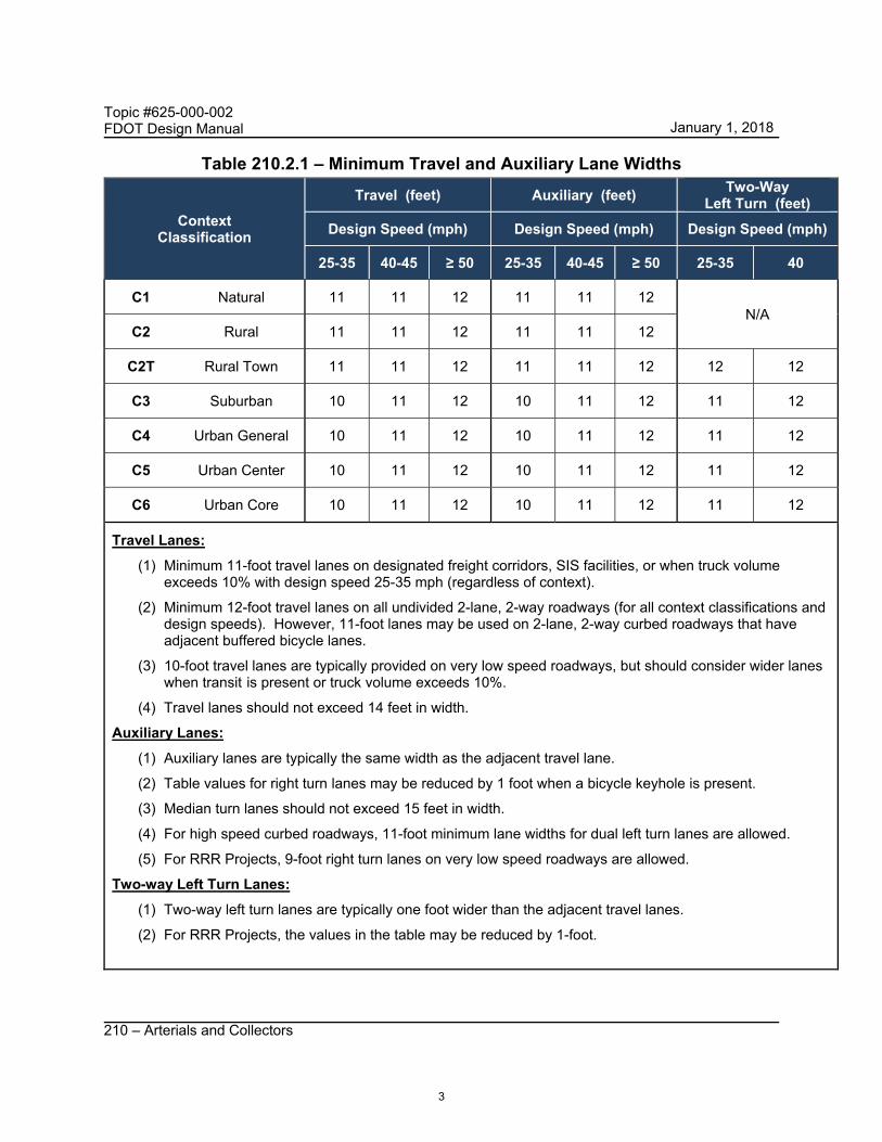
Design criteria for lane widths and pavement slopes are given by lane type, design speed and context classification. Minimum travel, auxiliary, and two-way left-turn lane widths are provided in Table 210.2.1. Refer to FDM 211 for ramp lane widths.
Two-way left turn lane widths (flush median) may be used on 3-lane and 5-lane typical sections with design speeds ≤ 40 mph. On new construction projects, flush medians are to include sections of raised or restrictive median to enhance vehicular, bicycle, and pedestrian safety, improve traffic efficiency, and attain the standards of the Access Management Classification of that highway system. Sections of raised or restrictive medians are recommended on RRR projects.
2
January 1, 2018
Topic #625-000-002 FDOT Design Manual
210 – Arterials and Collectors
Table 210.2.1 – Minimum Travel and Auxiliary Lane Widths
Context Classification
Travel (feet) Auxiliary (feet) Two-Way
Left Turn (feet)
Design Speed (mph) Design Speed (mph) Design Speed (mph)
25-35 40-45 ≥ 50 25-35 40-45 ≥ 50 25-35 40
C1 Natural 11 11 12 11 11 12 N/A
C2 Rural 11 11 12 11 11 12
C2T Rural Town 11 11 12 11 11 12 12 12
C3 Suburban 10 11 12 10 11 12 11 12
C4 Urban General 10 11 12 10 11 12 11 12
C5 Urban Center 10 11 12 10 11 12 11 12
C6 Urban Core 10 11 12 10 11 12 11 12
Travel Lanes:
(1) Minimum 11-foot travel lanes on designated freight corridors, SIS facilities, or when truck volume exceeds 10% with design speed 25-35 mph (regardless of context).
(2) Minimum 12-foot travel lanes on all undivided 2-lane, 2-way roadways (for all context classifications and design speeds). However, 11-foot lanes may be used on 2-lane, 2-way curbed roadways that have adjacent buffered bicycle lanes.
(3) 10-foot travel lanes are typically provided on very low speed roadways, but should consider wider lanes when transit is present or truck volume exceeds 10%.
(4) Travel lanes should not exceed 14 feet in width.
Auxiliary Lanes:
(1) Auxiliary lanes are typically the same width as the adjacent travel lane.
(2) Table values for right turn lanes may be reduced by 1 foot when a bicycle keyhole is present.
(3) Median turn lanes should not exceed 15 feet in width.
(4) For high speed curbed roadways, 11-foot minimum lane widths for dual left turn lanes are allowed.
(5) For RRR Projects, 9-foot right turn lanes on very low speed roadways are allowed.
Two-way Left Turn Lanes:
(1) Two-way left turn lanes are typically one foot wider than the adjacent travel lanes.
(2) For RRR Projects, the values in the table may be reduced by 1-foot.
3
January 1, 2018

Topic #625-000-002 FDOT Design Manual
210 – Arterials and Collectors
210.2.1 Bicycle Lanes
FDM 223 contains criteria for the accommodation of bicyclists.
210.2.2 Transit Facilities
Coordinate with the District Modal Development Office and local transit agency for the need for public transit facilities. FDM 225 contains additional guidelines for street side bus stop facilities, location and design.
Modification for Non-Conventional Projects:
Delete first sentence in above paragraph and see RFP for requirements.
210.2.3 On-Street Parking
On-street parking is a key element of urban contexts C6, C5, and C4, but may also be found in C2T. It provides necessary parking supply in these locations, helps manage traffic speeds, and provides separation between the sidewalk and the travel lanes. In these context zones, leave existing on-street parking in place unless local plans call for its removal. Where on street parking is not present in C6, C5, or C4, determine whether it should be added per local plan, for speed management or to increase available parking.
On-street parking is allowed on facilities with posted speeds of 35 mph or less. It is typically located at the outside edge of the roadway between the travel lane and the sidewalk. In C6 and C5 contexts it may sometimes be located within the median of a divided low speed urban street. Median parking provides additional parking supply as well as speed management.
Parking may be either parallel or angle (traditional or reverse). Parallel parking spaces are 8 feet wide, measured from the edge of the travel lane to the face of curb, and 22 feet long.
Angle parking spaces are 17 feet wide measured from the edge of the driving lane to the face of curb, with 45 degree angle stalls, 9 feet wide.
Use a 7-foot buffered bike lane per Exhibit 223-1 adjacent to parallel parking or use a shared lane if space does not permit a 7-foot buffered bike lane. Use a shared lane marking for the travel lane adjacent to reverse angle parking, instead of a bike lane, to provide cyclists with ample room to avoid the parked vehicles.
4
January 1, 2018

Topic #625-000-002 FDOT Design Manual
210 – Arterials and Collectors
Parking lane markings are 6-inch white.
Refer to FDM 212.11.5 for on-street parking restrictions. Refer to Chapter 316, F.S for laws governing parking spaces.
210.2.4 Pavement Cross Slopes
For roadways, the maximum number of travel lanes with cross slope in one direction is three lanes except as shown in Figure 210.2.1, which prescribes standard pavement cross slopes. A Design Variation or a Design Exception is required when proposed pavement cross slopes do not meet the requirements shown in Figure 210.2.1.
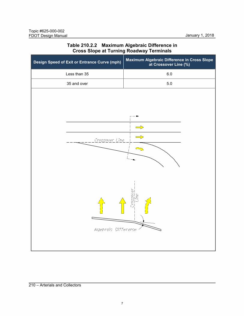
The maximum algebraic difference in cross slope between adjacent through lanes is 0.04. The maximum algebraic difference in cross slope between a through lane and an auxiliary lane at a turning roadway terminal is given in Table 210.2.2.
Cross slopes on bridges are to be on a uniform, straight-line rate, typically 0.02 (see FDM 260.4). Use transitions to adjust for differences in cross slope between the approach roadway section and the required straight-line slope for bridge decks. Whenever possible the transition should be accomplished on the roadway section, outside the limits of the bridge and approach slabs. This will require detailing of the transition(s) in the roadway plans. Coordination between the Roadway, Drainage and Structures designers in the development of transitions is required to ensure compatibility and harmonizing at bridge approaches.
5
January 1, 2018

Topic #625-000-002 FDOT Design Manual
210 – Arterials and Collectors
Figure 210.2.1 Standard Pavement Cross Slopes
All Travel Lanes One Direction
(1) These sections show only the standard slopes for adjoining travel lanes; they do not prescribe needed lanes, lane usage or typical section requirements other than lane slope. These slopes are not applicable to parabolic crowns.
(2) Maximum pavement cross slopes for tangent sections are: (a) 0.04 for design speeds of 45 mph or less (b) 0.03 for design speeds greater than 45 mph (c) 0.035 may only be used for 5-lanes sloped in one direction as shown above for all design
speeds. (3) The maximum change in cross slope between adjacent through lanes is 0.04. (4) Slopes on multi-purpose lanes may be 0.03 to 0.05. Portions of multi-purpose lanes that are
reserved for parking and access isles for the physically disabled are to have cross slopes not exceeding 1:50 (0.02) in all directions.
(5) 4 or more lanes sloped in one direction (*) may be used with design speed 65 mph or less and longitudinal grades not exceeding 5%.
6
January 1, 2018
Topic #625-000-002 FDOT Design Manual
210 – Arterials and Collectors
Table 210.2.2 Maximum Algebraic Difference in Cross Slope at Turning Roadway Terminals
Design Speed of Exit or Entrance Curve (mph) Maximum Algebraic Difference in Cross Slope at Crossover Line (%)
Less than 35 6.0
35 and over 5.0
7
January 1, 2018
Topic #625-000-002 FDOT Design Manual
210 – Arterials and Collectors
210.2.4.1 RRR Criteria for Cross Slopes
Review the existing pavement and shoulder cross slopes for compliance with criteria. Field verify existing pavement and shoulder cross slopes by one of the following:
(1) Full Digital Terrain Model for the roadway width – evaluate cross slope on tangent sections at 100-foot intervals.
(2) Vehicle Mounted Scanner – prior to design, using the results of the scan, determine roadway limits where cross slope is potentially out of tolerance and request Digital Terrain Model of the roadway width for these limits. Evaluate cross slope on tangent sections at 100-foot intervals.
If cross slopes do not meet the values in Table 210.2.3, additional cross sections may be required to develop cross slope correction details and estimate material quantities. Resurfaced pavement and shoulder cross slopes should meet new construction criteria. When cross slope correction is not practical, documentation in the design file is required. If existing conditions are within the allowable range shown in Table 210.2.3, the term “Match Existing” may be used on the Typical Section(s) to indicate that the existing cross slope is to remain. Superelevation requirements are covered in FDM 210.9.
When cross slope correction is necessary, work closely with the District Pavement Design Engineer and the District Bituminous Engineer to determine the appropriate method of correction. Tabulate existing cross slopes in the plans at 100-foot intervals within the limits of cross slope correction. Include cross slope correction details showing the method of correction in the plans (see examples in FDM 306). Do not show cross slope correction details on the roadway cross sections. Base cross slope correction material quantities on the method of correction shown in cross slope correction details.
8
January 1, 2018
Topic #625-000-002 FDOT Design Manual
210 – Arterials and Collectors
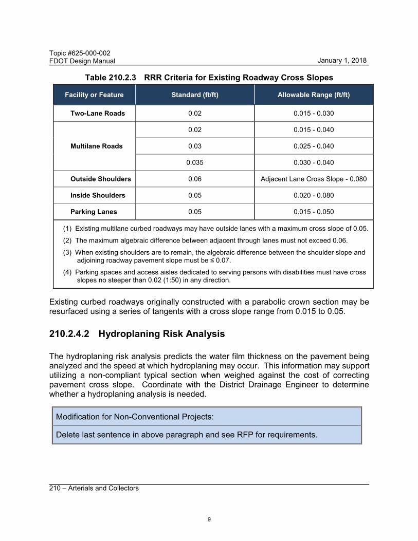
Table 210.2.3 RRR Criteria for Existing Roadway Cross Slopes
Facility or Feature Standard (ft/ft) Allowable Range (ft/ft)
Two-Lane Roads 0.02 0.015 - 0.030
Multilane Roads
0.02 0.015 - 0.040
0.03 0.025 - 0.040
0.035 0.030 - 0.040
Outside Shoulders 0.06 Adjacent Lane Cross Slope - 0.080
Inside Shoulders 0.05 0.020 - 0.080
Parking Lanes 0.05 0.015 - 0.050
(1) Existing multilane curbed roadways may have outside lanes with a maximum cross slope of 0.05.
(2) The maximum algebraic difference between adjacent through lanes must not exceed 0.06.
(3) When existing shoulders are to remain, the algebraic difference between the shoulder slope and adjoining roadway pavement slope must be ≤ 0.07.
(4) Parking spaces and access aisles dedicated to serving persons with disabilities must have cross slopes no steeper than 0.02 (1:50) in any direction.
Existing curbed roadways originally constructed with a parabolic crown section may be resurfaced using a series of tangents with a cross slope range from 0.015 to 0.05.
210.2.4.2 Hydroplaning Risk Analysis
The hydroplaning risk analysis predicts the water film thickness on the pavement being analyzed and the speed at which hydroplaning may occur. This information may support utilizing a non-compliant typical section when weighed against the cost of correcting pavement cross slope. Coordinate with the District Drainage Engineer to determine whether a hydroplaning analysis is needed.
Modification for Non-Conventional Projects:
Delete last sentence in above paragraph and see RFP for requirements.
9
January 1, 2018
Topic #625-000-002 FDOT Design Manual
210 – Arterials and Collectors
When a hydroplaning risk analysis is performed, use the HP Program and the Design Guidance: Hydroplaning Risk Analysis. The Hydroplaning Tools can be downloaded under Design Aids at: http://www.fdot.gov/roadway/Drainage/ManualsandHandbooks.shtm
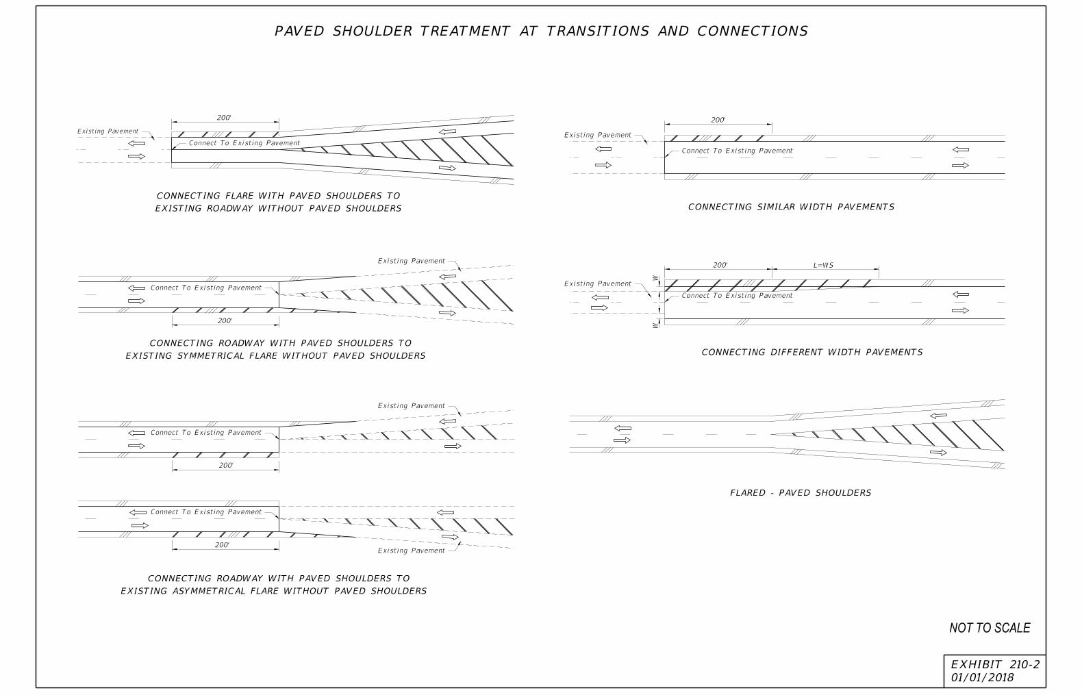
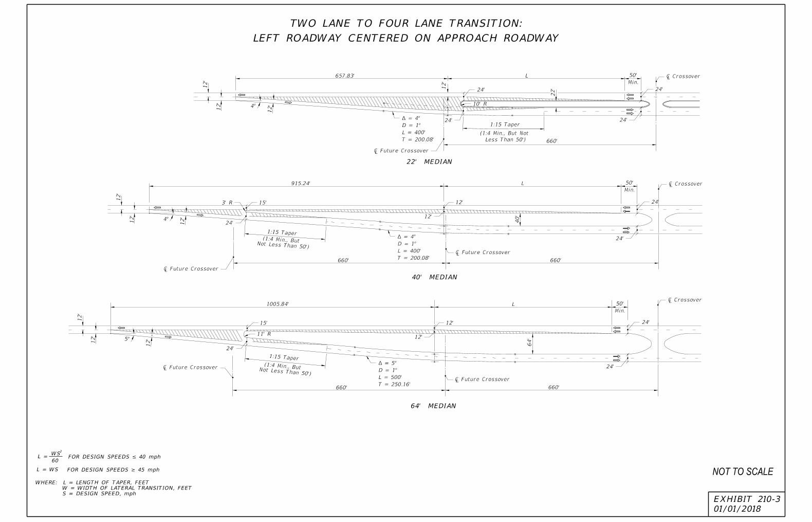
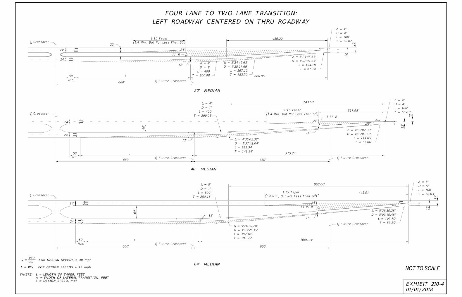
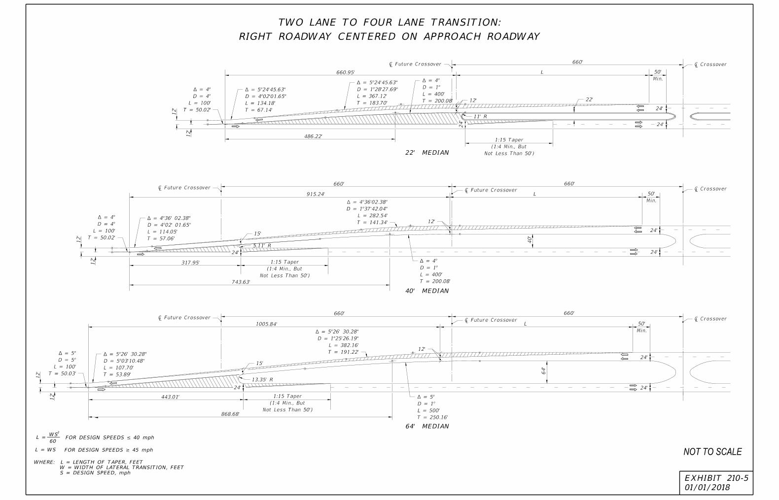
210.2.5 Roadway Transitions
The minimum merging roadway transition length (L) is calculated as follows: (1) Use L = (W*S2)/60 for design speeds ≤ 40 mph (2) Use L = W*S for design speeds ≥ 45 mph
Where: L = length of taper, feet W = width of lateral transition, feet S = design speed, mph
Exhibit 210-1 through 210-6 illustrate standard roadway transitions. For conditions not addressed in these figures, use the following minimum taper lengths:
• Merging Taper = L
• Shifting Taper = L/2
• Shoulder Taper = L/3
Where an abrupt change in roadway typical (e.g., 4-lane section to a 6-lane section) a striped lane transition may be considered when all the following conditions are met:
• New pavement widths are not substantially greater than the joining pavement,
• Grade differentials are slight, and
• Future widening is expected.
210.2.6 Number of Lanes on the State Highway System
See Section 335.02(3) of the Florida Statutes for the number of lanes to be provided on the State Highway System. Nothing in this statute precludes a number of lanes in excess of ten lanes. The Department will determine the appropriate number of lanes based on traffic demand. Consideration will be given to availability of right of way and the capacity to accommodate other modes of transportation within existing rights of way.
Exceptions to Section 335.02(3) of the Florida Statutes will be addressed on a case-by-case basis, with final approval resting with the Secretary of Transportation.
10
January 1, 2018

01/01/2018
EXHIBIT 210-1
4-LANE DIVIDED TO 4-LANE UNDIVIDED
4-LANE DIVIDED TO 2-LANE UNDIVIDED
4-LANE UNDIVIDED TO 2-LANE UNDIVIDED
L*
L*
LANE DIVERGENCE AND CONVERGENCE FOR CENTERED ROADWAYS
L**
L**
2L*
L = WS
2
60FOR DESIGN SPEEDS ≤ 40 mph
FOR DESIGN SPEEDS ≥ 45 mphL = WS
** W = 1/2 MEDIAN WIDTH
* W = ONE LANE WIDTH
S = DESIGN SPEED, mph
W = WIDTH OF LATERAL TRANSITION, FEET
WHERE: L = LENGTH OF TAPER, FEET NOT TO SCALE
01/01/2018
EXHIBIT 210-2
EXISTING ROADWAY WITHOUT PAVED SHOULDERS
CONNECTING FLARE WITH PAVED SHOULDERS TO
CONNECTING SIMILAR WIDTH PAVEMENTS
CONNECTING DIFFERENT WIDTH PAVEMENTSEXISTING SYMMETRICAL FLARE WITHOUT PAVED SHOULDERS
CONNECTING ROADWAY WITH PAVED SHOULDERS TO
EXISTING ASYMMETRICAL FLARE WITHOUT PAVED SHOULDERS
CONNECTING ROADWAY WITH PAVED SHOULDERS TO
FLARED - PAVED SHOULDERS
200'200'
200'
200' L=WS
WW
200'
200'
Connect To Existing Pavement
Existing Pavement
Connect To Existing Pavement
Existing Pavement
Connect To Existing Pavement
Existing PavementConnect To Existing Pavement
Connect To Existing Pavement
Connect To Existing Pavement
Existing Pavement
Existing Pavement
Existing Pavement
PAVED SHOULDER TREATMENT AT TRANSITIONS AND CONNECTIONS
NOT TO SCALE
01/01/2018
EXHIBIT 210-3
22' MEDIAN
40' MEDIAN
64' MEDIAN
12'
12'
4°
12'
657.83'
12'
660'
1:15 Taper
(1:4 Min., But Not
Less Than 50')
22'
Min.
50'
12'
12'
4°
12'
Not Less Than 50')
660' 660'
915.24'
Min.
50'
40'
12'
12'
5°
12'
660'
1005.84'
660'
64'
Not Less Than 50')
Min.
50'
T = 200.08'
L = 400'
D = 1°
¬ = 4°
¡ Future Crossover
24'
24'
10' R
24'
24'
¡ Crossover
24'
24'
¡ Crossover
T = 200.08'
L = 400'
D = 1°
¬ = 4°
12'
12'
¡ Future Crossover
¡ Future Crossover
15'
24'
3' R
1:15 Taper(1:4 Min., But
15'
24'
1:15 Taper
(1:4 Min., But
11' R
T = 250.16'
L = 500'
D = 1°
¬ = 5°
¡ Future Crossover
12'
12'
¡ Future Crossover
24'
24'
¡ Crossover
LEFT ROADWAY CENTERED ON APPROACH ROADWAY
TWO LANE TO FOUR LANE TRANSITION:
L = WS
2
60FOR DESIGN SPEEDS ≤ 40 mph
FOR DESIGN SPEEDS ≥ 45 mphL = WS
S = DESIGN SPEED, mph
W = WIDTH OF LATERAL TRANSITION, FEET
WHERE: L = LENGTH OF TAPER, FEET
L
L
L
NOT TO SCALE
01/01/2018
EXHIBIT 210-4
22' MEDIAN
40' MEDIAN
64' MEDIAN
(1:4 Min., But Not Less Than 50')
1:15 Taper 486.22'
660.95'
660'
12'
12'
24'24'
24'
Min.
50'
24'
24'
Min.
50'
Min.
50'
24'
24'
64'
660'
660'
40'
743.63'
317.95'
915.24'
660'
660'
1005.84'
868.68'
443.01'
(1:4 Min., But Not Less Than 50')
1:15 Taper
(1:4 Min., But Not Less Than 50')
1:15 Taper
12'
12'
24'
24'
12'
12'
T = 50.02'
L = 100'
D = 4°
¬ = 4°
T = 67.14'
L = 134.18'
D = 4°02'01.65"
¬ = 5°24'45.63"
T = 183.70'
L = 367.12'
D = 1°28'27.69"
¬ = 5°24'45.63"
T = 200.08'
L = 400'
D = 1°
¬ = 4°
11' R
12'
¡ Future Crossover
22'¡ Crossover
¡ Crossover
¡ Crossover
¡ Future Crossover
¡ Future Crossover
12'
12'
T = 200.08'
L = 400'
D = 1°
¬ = 4°
T = 141.34'
L = 282.54'
D = 1°37'42.04"
¬ = 4°36'02.38"
15'
5.11' R
T = 57.06'
L = 114.05'
D = 4°02'01.65"
¬ = 4°36'02.38"
T = 50.02'
L = 100'
D = 4°
¬ = 4°
¡ Future Crossover
¡ Future Crossover
15'
13.35' R
T = 250.16'
L = 500'
D = 1°
¬ = 5°
T = 191.22'
L = 382.16'
D = 1°25'26.19"
¬ = 5°26'30.28"
T = 50.03'
L = 100'
D = 5°
¬ = 5°
T = 53.89'
L = 107.70'
D = 5°03'10.48"
¬ = 5°26'30.28"
LEFT ROADWAY CENTERED ON THRU ROADWAY
FOUR LANE TO TWO LANE TRANSITION:
L = WS
2
60FOR DESIGN SPEEDS ≤ 40 mph
FOR DESIGN SPEEDS ≥ 45 mphL = WS
S = DESIGN SPEED, mph
W = WIDTH OF LATERAL TRANSITION, FEET
WHERE: L = LENGTH OF TAPER, FEET
L
L
L
NOT TO SCALE
01/01/2018
EXHIBIT 210-5
64' MEDIAN
40' MEDIAN
22' MEDIAN
660.95'
660'
660'
915.24'
660'
1005.84'
660' 660'
64'
868.68'
443.01'12'
12'
24' 24'
24'
12'
12'
317.95'
743.63'
24'
40'
24'
24'
12'
12'
486.22'
24'
24'24'
Not Less Than 50')
(1:4 Min., But
1:15 Taper
Not Less Than 50')
(1:4 Min., But
1:15 Taper
Not Less Than 50')
(1:4 Min., But
1:15 Taper
Min.
50'
Min.
50'
Min.
50'
T = 50.02'
L = 100'
D = 4°
¬ = 4°
T = 67.14'
L = 134.18'
D = 4°02'01.65"
¬ = 5°24'45.63"
T = 183.70'
L = 367.12'
D = 1°28'27.69"
¬ = 5°24'45.63"
T = 200.08'
L = 400'
D = 1°
¬ = 4°
11' R
12'
¡ Future Crossover ¡ Crossover
22'
T = 50.02'
L = 100'
D = 4°
¬ = 4°
T = 57.06'
L = 114.05'
D = 4°02' 01.65"
¬ = 4°36' 02.38"
¡ Future Crossover
5.11' R
T = 141.34'
L = 282.54'
D = 1°37'42.04"
¬ = 4°36'02.38"
T = 200.08'
L = 400'
D = 1°
¬ = 4°
¡ Crossover
¡ Crossover
¡ Future Crossover
15'
12'
T = 50.03'
L = 100'
D = 5°
¬ = 5°
T = 53.89'
L = 107.70'
D = 5°03'10.48"
¬ = 5°26' 30.28"
¡ Future Crossover
15'
T = 191.22'
L = 382.16'
D = 1°25'26.19"
¬ = 5°26' 30.28"
¡ Future Crossover
12'
T = 250.16'
L = 500'
D = 1°
¬ = 5°
13.35' R
RIGHT ROADWAY CENTERED ON APPROACH ROADWAY
TWO LANE TO FOUR LANE TRANSITION:
L = WS
2
60FOR DESIGN SPEEDS ≤ 40 mph
FOR DESIGN SPEEDS ≥ 45 mphL = WS
S = DESIGN SPEED, mph
W = WIDTH OF LATERAL TRANSITION, FEET
WHERE: L = LENGTH OF TAPER, FEET
L
L
L
NOT TO SCALE

01/01/2018
EXHIBIT 210-6
22' MEDIAN
40' MEDIAN
64' MEDIAN
660'
24'
24'
1005.84'
660'
12'
12'
12'
12'
12'
12'
4°
24'
40'
915.24'
24'
24'
660' 660'
24'
24'
657.83' 12'
12'
4°12'
660'
Not Less Than 50')
(1:4 Min., But
1:15 Taper
Not Less Than 50')
(1:4 Min., But
1:15 Taper
Not Less Than 50')
(1:4 Min., But
1:15 Taper
Min.
50'
Min.
50'
Min.
50'
5°
¡ Crossover
¡ Future Crossover
¡ Crossover ¡ Future Crossover
¡ Crossover ¡ Future Crossover
64'
22'
24'
24'
10' R
12'
T = 200.08'
L = 400'
D = 1°
¬ = 4°
¡ Future Crossover
T = 200.08'
L = 400'
D = 1°
¬ = 4°
12' 15' 3' R
T = 250.16'
L = 500'
D = 1°
¬ = 5°
12'
24'
15' 11' R
¡ Future Crossover
RIGHT ROADWAY CENTERED ON THRU ROADWAY
FOUR LANE TO TWO LANE TRANSITION:
L = WS
2
60FOR DESIGN SPEEDS ≤ 40 mph
FOR DESIGN SPEEDS ≥ 45 mphL = WS
S = DESIGN SPEED, mph
W = WIDTH OF LATERAL TRANSITION, FEET
WHERE: L = LENGTH OF TAPER, FEET
L
L
L
NOT TO SCALE

Topic #625-000-002 FDOT Design Manual
210 – Arterials and Collectors
210.3 Median
Median width is expressed as the dimension between the inside edges of traveled way. Medians perform the following functions:
• Provide separation of opposing traffic to minimize risk of head on crashes,
• Provide a recovery area for errant vehicles,
• Provide a stopping area in case of emergencies,
• Allow space for speed changes and storage of left-turning and U-turning vehicles,
• Minimize headlight glare,
• Provide width for future lanes,
• Provide pedestrian refuge,
• Control access.
Provide a raised or restrictive median on divided roadways that have a design speed of 45 mph or greater. Median widths for divided roadways are given in Table 210.3.1.
Median ditches must be designed to meet the following requirements:
• Have sufficient depth to provide positive drainage of the adjacent sub-grades.Typically, this requires a median depth of at least one foot below the sub-gradeshoulder point.
• Have recoverable side slopes within the clear zone in order to facilitate therecovery of errant vehicles. See FDM 215 for additional information on roadsidesafety.
• Have sufficient longitudinal gradient and hydraulic capacity to ensure gooddrainage.
210.3.1 Bridge Median
See FDM 260.5 for information on bridge medians.
17
January 1, 2018

Topic #625-000-002 FDOT Design Manual
210 – Arterials and Collectors
Table 210.3.1 Median Widths
Context Classification
Curbed Roadways and Flush Shoulder Roadways
(feet)
High Speed Curbed
Roadways (feet)
Flush Shoulder Roadways
(feet)
Design Speed (mph)
25-35 40-45 50-55 ≥ 50
C1 Natural N/A N/A 30 40
C2 Rural N/A N/A 30 40
C2T Rural Town 15.5 22 N/A N/A
C3 Suburban 22 22 30 40
C4 Urban General 15.5 22 N/A N/A
C5 Urban Center 15.5 N/A N/A N/A
C6 Urban Core 15.5 N/A N/A N/A
(1) On reconstruction projects where existing curb locations are fixed due to severe right of way constraints, the minimum median width may be reduced to 19.5 feet for design speeds = 45 mph, and to 15.5 feet for design speeds ≤ 40 mph.
(2) A minimum 6-foot median may be used within C5 and C6 context classifications only where left turn lanes are not expected.
210.4 Shoulders
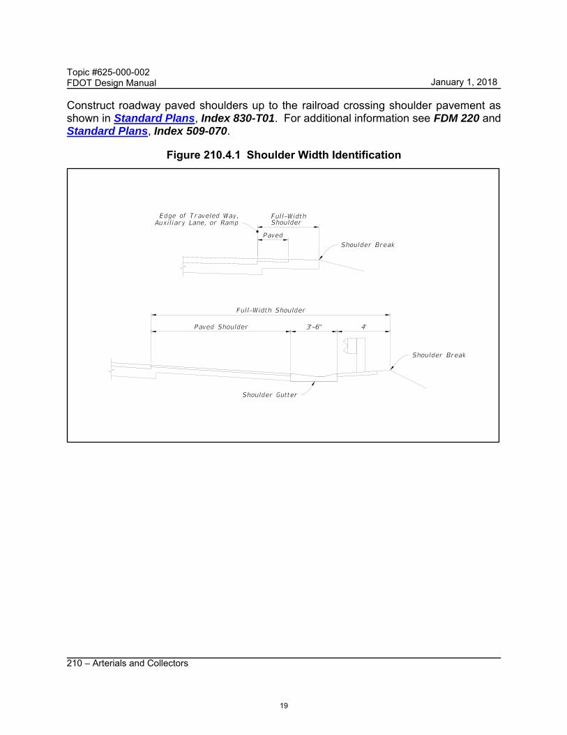
Roadway shoulder width is measured from the edge of the traveled way to the shoulder break. A portion of the shoulder is required to be paved on all roadways on the State Highway System. Shoulder widths for roadways are given in Table 210.4.1. See Figure 210.4.1 for an illustration of roadway shoulders. Refer to FDM 211 for ramp shoulder widths. Refer to FDM 260.3 for bridge shoulder widths.
18
January 1, 2018
Topic #625-000-002 FDOT Design Manual
210 – Arterials and Collectors
Construct roadway paved shoulders up to the railroad crossing shoulder pavement as shown in Standard Plans, Index 830-T01. For additional information see FDM 220 and Standard Plans, Index 509-070.
Figure 210.4.1 Shoulder Width Identification
19
January 1, 2018
Topic #625-000-002 FDOT Design Manual
210 – Arterials and Collectors
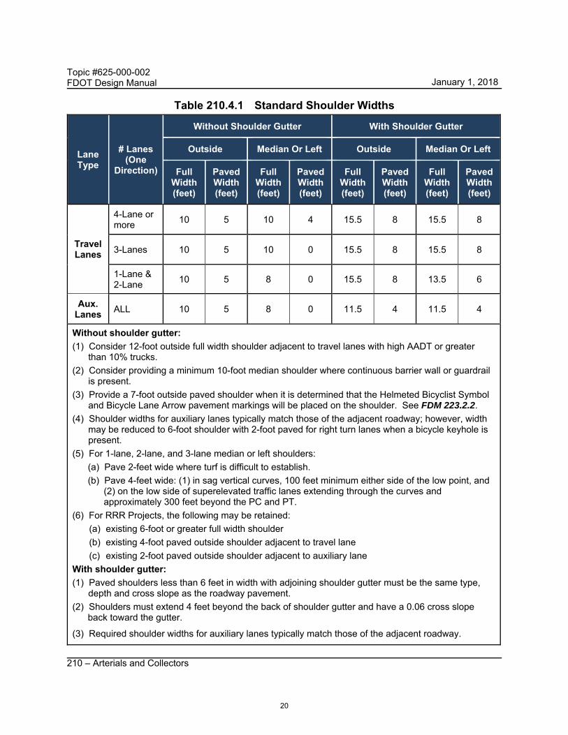
Table 210.4.1 Standard Shoulder Widths
Lane Type
# Lanes (One
Direction)
Without Shoulder Gutter With Shoulder Gutter
Outside Median Or Left Outside Median Or Left
Full Width (feet)
Paved Width(feet)
Full Width(feet)
Paved Width(feet)
Full Width(feet)
Paved Width (feet)
Full Width (feet)
Paved Width(feet)
Travel Lanes
4-Lane or more
10 5 10 4 15.5 8 15.5 8
3-Lanes 10 5 10 0 15.5 8 15.5 8
1-Lane & 2-Lane
10 5 8 0 15.5 8 13.5 6
Aux. Lanes
ALL 10 5 8 0 11.5 4 11.5 4
Without shoulder gutter:
(1) Consider 12-foot outside full width shoulder adjacent to travel lanes with high AADT or greater than 10% trucks.
(2) Consider providing a minimum 10-foot median shoulder where continuous barrier wall or guardrail is present.
(3) Provide a 7-foot outside paved shoulder when it is determined that the Helmeted Bicyclist Symbol and Bicycle Lane Arrow pavement markings will be placed on the shoulder. See FDM 223.2.2.
(4) Shoulder widths for auxiliary lanes typically match those of the adjacent roadway; however, width may be reduced to 6-foot shoulder with 2-foot paved for right turn lanes when a bicycle keyhole is present.
(5) For 1-lane, 2-lane, and 3-lane median or left shoulders:
(a) Pave 2-feet wide where turf is difficult to establish.
(b) Pave 4-feet wide: (1) in sag vertical curves, 100 feet minimum either side of the low point, and (2) on the low side of superelevated traffic lanes extending through the curves and approximately 300 feet beyond the PC and PT.
(6) For RRR Projects, the following may be retained:
(a) existing 6-foot or greater full width shoulder
(b) existing 4-foot paved outside shoulder adjacent to travel lane
(c) existing 2-foot paved outside shoulder adjacent to auxiliary lane
With shoulder gutter:
(1) Paved shoulders less than 6 feet in width with adjoining shoulder gutter must be the same type, depth and cross slope as the roadway pavement.
(2) Shoulders must extend 4 feet beyond the back of shoulder gutter and have a 0.06 cross slope back toward the gutter.
(3) Required shoulder widths for auxiliary lanes typically match those of the adjacent roadway.
20
January 1, 2018
Topic #625-000-002 FDOT Design Manual
210 – Arterials and Collectors
210.4.1 Shoulder Cross Slopes
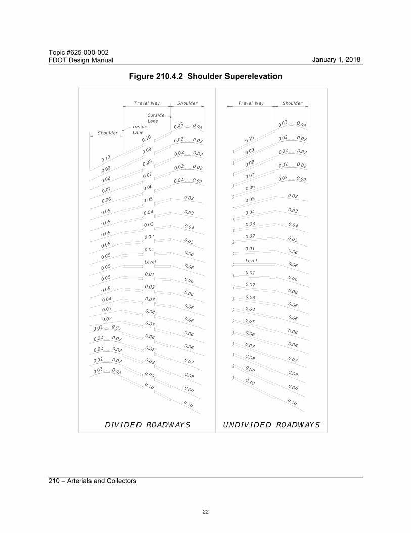
The standard cross slope is 0.06 on the outside shoulder and 0.05 on the median (or left) side. Figure 210.4.2 illustrates shoulder cross slopes in relationship to roadway cross slopes for normal and superelevated sections. For 5-foot (or less) paved shoulders, see Figure 210.4.3. If the inside travel lane is sloping toward the median, then the inside shoulder cross slope may be increased to 0.06.
For projects constructed with concrete pavement, the first one foot of the outside shoulder is cast with the outside travel lane and will have the same cross slope (and superelevation) as the outside lane. Superelevation of the shoulder pavement is to be rotated about the outside edge of the outside slab.
For shoulder cross slope criteria on bridges see FDM 260.4.
21
January 1, 2018
Topic #625-000-002 FDOT Design Manual
210 – Arterials and Collectors
Figure 210.4.2 Shoulder Superelevation
22
January 1, 2018

Topic #625-000-002 FDOT Design Manual
210 – Arterials and Collectors
Figure 210.4.3 Special Shoulder Superelevation
23
January 1, 2018
Topic #625-000-002 FDOT Design Manual
210 – Arterials and Collectors
210.4.2 Typical Paving under Bridge
See FDM 260.7 for requirements for paving under bridges.
210.4.3 Limits of Friction Course on Paved Shoulders
Extend friction course (closed and open graded) over the full width of the median and outside paved shoulders.
210.4.4 RRR Shoulder Treatment
Identify the shoulder treatment option in the plans when using Standard Plans, Index 570-010. Use Treatment I only if the shoulder is established with good soil and turf, and there is no significant shoulder erosion. Use Treatment II when an existing shoulder meets the overlay thickness requirements for Treatment I, but there is significant shoulder erosion.
210.4.5 Narrow Bridge Shoulder Warning Devices
The Standard Plans, Index 700-106, provides details for the shoulder treatment to be used on flush shoulder roadway approaches to a narrow bridge. This index provides standards for the placement of signing, striping, object markers and raised pavement marking (RPMs) for use at structures where the bridge shoulder width is less than the width of the useable shoulder on the approach roadway.
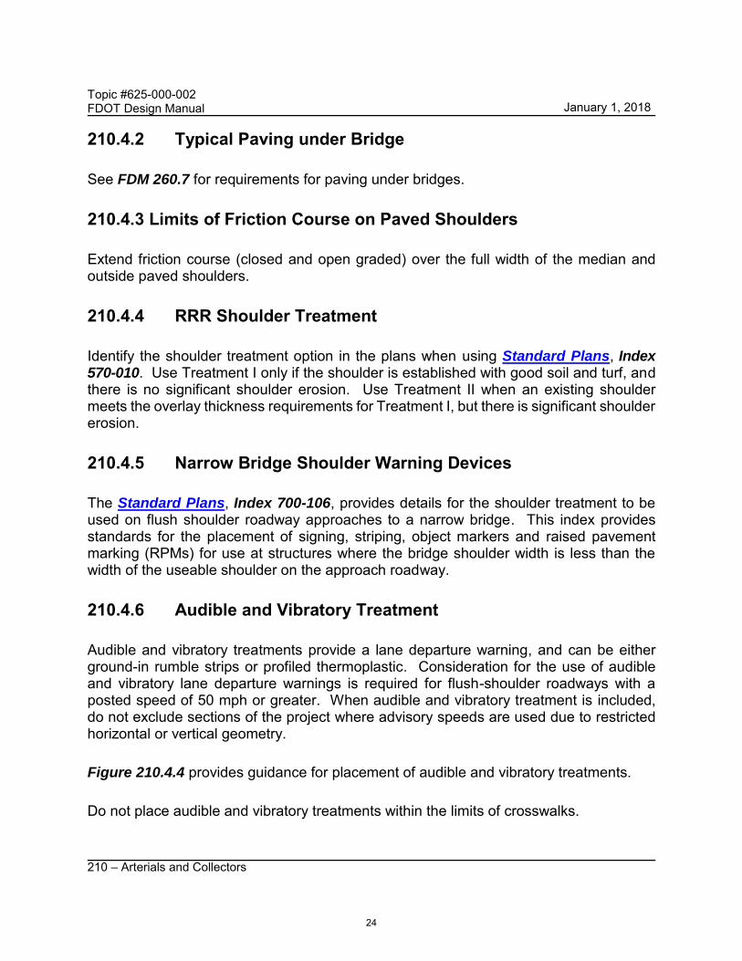
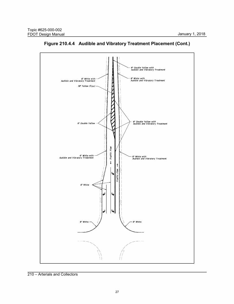
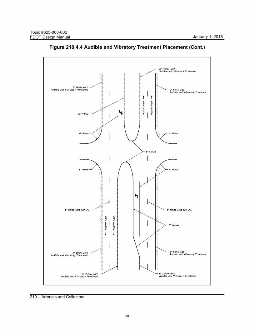
210.4.6 Audible and Vibratory Treatment
Audible and vibratory treatments provide a lane departure warning, and can be either ground-in rumble strips or profiled thermoplastic. Consideration for the use of audible and vibratory lane departure warnings is required for flush-shoulder roadways with a posted speed of 50 mph or greater. When audible and vibratory treatment is included, do not exclude sections of the project where advisory speeds are used due to restricted horizontal or vertical geometry.
Figure 210.4.4 provides guidance for placement of audible and vibratory treatments.
Do not place audible and vibratory treatments within the limits of crosswalks.
24
January 1, 2018

Topic #625-000-002 FDOT Design Manual
210 – Arterials and Collectors
210.4.6.1 Ground-in Rumble Strips
See Usage Criteria in the Developmental Standard Plans Instructions (DSPI) for Index D546-020 to determine if Index D546-020 should be requested and used on the project.
210.4.6.2 Profiled Thermoplastic
Typically, profiled thermoplastic is used as follows:
• When it is not practical or desirable to install ground-in rumble strips
• Inside and outside edge line pavement markings on roadways with rigid pavementshoulders.
• Edge lines on two-lane roadways that do not have paved shoulders.
• Edge lines on bridges with narrow shoulders as a countermeasure for barrier impacts.
Additional guidance on the use of profiled thermoplastic is provided in the Developmental Standard Plans Instructions (DSPI) for Index D546-020.
25
January 1, 2018

Topic #625-000-002 FDOT Design Manual
210 – Arterials and Collectors
Figure 210.4.4 Audible and Vibratory Treatment Placement
26
January 1, 2018
Topic #625-000-002 FDOT Design Manual
210 – Arterials and Collectors
Figure 210.4.4 Audible and Vibratory Treatment Placement (Cont.)
27
January 1, 2018
Topic #625-000-002 FDOT Design Manual
210 – Arterials and Collectors
Figure 210.4.4 Audible and Vibratory Treatment Placement (Cont.)
28
January 1, 2018
Topic #625-000-002 FDOT Design Manual
210 – Arterials and Collectors
Figure 210.4.4 Audible and Vibratory Treatment Placement (Cont.)
29
January 1, 2018

Topic #625-000-002 FDOT Design Manual
210 – Arterials and Collectors
Figure 210.4.4 Audible and Vibratory Treatment Placement (Cont.)
30
January 1, 2018
Topic #625-000-002 FDOT Design Manual
210 – Arterials and Collectors
210.5 Curbed Roadways
The term “curbed” includes all types of curb, and curb and gutter that are used on the state highway system and detailed in Standard Plans, Index 520-001.
The method of collecting and conveying drainage runoff and the availability of R/W determines the cross section; i.e. flush shoulder or curbed. When it is determined that a closed drainage system will be used, the selection of curb type will be based on the design speed.
Curbed roadways with design speeds of 45 mph or less, typically use Type F curb on the outside and Type E curb on the median (or left) side.
See FDM 215.2.7.2, for additional information regarding curbs and their placement.
210.5.1 High-Speed Curbed Roadways
Curbs may be used on roadways where the anticipated operating speeds require a design speed of 50-55 mph and:
(1) Curbs are necessary to control drainage, or (2) R/W is constrained
High speed curbed sections are typically used within C3 context classification and transitional areas.
High speed curbed roadways are to use Type E curb on both the median and outside. Provide an offset from the edge of the traveled way to the lip of the curb as follows:
(1) 4-foot to median curb for 4-lane roadway sections. (2) 6.5-foot to median curb for 6-lane roadway sections. (3) 6.5-foot to outside curb for all roadway sections.
210.6 Roadside Slopes
Criteria and details for roadside slopes are included in FDM 215.
31
January 1, 2018
Topic #625-000-002 FDOT Design Manual
210 – Arterials and Collectors
210.7 Border Width
Border width provides space for: (1) Roadside design components such as signing, signals, lighting, drainage features,
guardrail, fencing and clear zone, sidewalks with ADA provisions, traffic control devices, fire hydrants, storm drainage features, bus and transit features, permitted public utilities and space for aesthetic features such as sod and other landscape items.
(2) A buffer between vehicles and pedestrians, (3) Construction and maintenance of the facility, and (4) Permitted public utilities.
Required border width is provided in Table 210.7.1. Border width is measured to the R/W line as follows:
• Flush shoulder roadways: from the shoulder break.
• Curbed roadways: from the outside edge of the pavement (lip of gutter).
• High-speed curbed roadways: from the outside edge of the traveled way.
32
January 1, 2018

Topic #625-000-002 FDOT Design Manual
210 – Arterials and Collectors
Table 210.7.1 Minimum Border Width
Context Classification
Minimum Border Width (Feet)
Curbed and High-Speed Curbed Design Speed (mph)
Flush Shoulder Design Speed (mph)
25-40 45 50 55 25-45 ≥ 50
C1 Natural N/A N/A 29 35 N/A 40
C2 Rural N/A N/A 29 35 N/A 40
C2T Rural Town 12 14 N/A N/A 33 N/A
C3 Suburban 12 14 29 35 33 40
C4 Urban General 12 14 N/A N/A 33 N/A
C5 Urban Center 12 N/A N/A N/A N/A N/A
C6 Urban Core 14 N/A N/A N/A N/A N/A
(1) On low speed curbed roadways that have an adjacent bike lane, the required border width shown in the table may be reduced by 2 feet.
(2) On existing roadways where R/W cannot be acquired or where the decision has been made to simply maintain and preserve the facility, the absolute minimum border under these conditions is 8 feet. No Design Variation is required for this condition.
(3) On existing roadways where R/W is being acquired for other reasons, the minimum border width should be that used for new construction projects; however, the minimum length of wider border width must be a segment of sufficient length to provide reasonable continuity.
33
January 1, 2018
Topic #625-000-002 FDOT Design Manual
210 – Arterials and Collectors
210.8 Horizontal Alignment
The centerline (CL) or baseline (BL) of construction defines the horizontal alignment for roadway and bridge construction. The CL or BL of construction is a series of tangents connected by horizontal curves established by the Engineer of Record (EOR). CL or BL of construction may be the same alignment as the BL of survey.
Horizontal alignment should be consistent with the expected posted speed and with environmental, physical, and economic constraints. Design speed is the principal factor controlling horizontal alignment.
Avoid placing horizontal curves, point of intersection (PI), and superelevation transitions within the limits of a structure or approach slabs. Placement of stationing equations within the limits of a structure should be avoided on contract plans. Such equations unnecessarily increase the probability of error in both the design and construction phase.
210.8.1 Deflections in Alignment
The point where tangents intersect is known as the PI. Although the use of a PI with no horizontal curve is discouraged, there may be conditions where it is necessary. The maximum deflection without a horizontal curve are as follows:
Flush shoulder and curbed roadways with design speed 40 mph and less is2o00’00”.
Flush shoulder roadways with design speed 45 mph and greater is 0o45’00”.
Curbed roadways with design speed 45 mph and greater is 1o00’00”.
High speed curbed roadways with design speed 50 mph and greater is 0o45’00”.
210.8.1.1 Intersections
Refer to FDM 212 for information regarding deflections through intersections.
210.8.2 Horizontal Curves
A horizontal curve should not be introduced near the crest of a vertical curve. The combination of horizontal and vertical curves can greatly reduce sight distance; i.e., hide the horizontal curve from the approaching driver. The hazard can be avoided by having
34
January 1, 2018

Topic #625-000-002 FDOT Design Manual
210 – Arterials and Collectors
the horizontal curvature lead the vertical curvature; i.e., the horizontal curve is made longer than the vertical curve.
Flatter curvature with shorter tangents is preferable to sharp curves connected by long tangents; i.e., avoid using minimum horizontal curve lengths.
Table 210.8.1 provides the horizontal curve lengths to be used in establishing the horizontal alignment. Refer to Table 210.8.3 for compound curves.
Table 210.8.1 Length of Horizontal Curve
Desired Length Based on Design Speed (mph)
mph 25 30 35 40 45 50 55 60 65 70
feet 400 450 525 600 675 750 825 900 975 1050
Desired Length Based on Deflection Angle (1) The desired horizontal curve length shall
be the greater of the lengths based on design speed and length based on deflection angle.
(2) When desirable horizontal curve length cannot be attained, provide the greatest attainable length possible, but not less than 400 feet.
degrees 5o 4o 3o 2o 1o
feet 500 600 700 800 900
210.8.2.1 Existing Horizontal Curves
Evaluate existing curves against the values shown in Table 210.8.2. The review should include an on-site review for evidence of roadway departure or operational problems in the area of concern.
35
January 1, 2018

Topic #625-000-002 FDOT Design Manual
210 – Arterials and Collectors
Table 210.8.2 Minimum Radius for Evaluation of Existing Horizontal Curves
Maximum Superelevation
(emax)
Minimum Radius (feet)
Design Speed (mph)
25 30 35 40 45 50 55 60 65 70
0.10 SHS 160 231 323 432 559 694 881 1091 1348 1637
RRR 120 188 276 388 521 674 849 1042 1273 1528
0.05 SHS 194 286 402 533 694 881 N/A N/A N/A N/A
RRR 140 223 332 468 637 849 N/A N/A N/A N/A
Condition #1 – A horizontal curve that meets or exceeds the SHS minimum radius shown in Table 210.8.2 is satisfactory unless there is a significant crash history (3 or more crashes within the most recent available certified 5-year data) or other evidence of safety or operational problems. If problems are identified, include corrective measures in the project.
Condition #2 – A horizontal curve that is below the SHS minimum radius shown in Table 210.8.2, but meets or exceeds the RRR minimum radius shown in Table 210.8.2 must be reviewed for specific safety problems at the curve. If the review indicated significant operational or safety problems exist, the curve should be reconstructed. If problems are identified but reconstruction is not warranted, include corrective measures in the project.
Condition #3 – A horizontal curve that does not meet the RRR minimum radius shown in Table 210.8.2 must be reconstructed or a Design Exception or Design Variation obtained. A reconstructed curve must meet the new construction values shown in Tables 210.8.1, 210.9.1, 210.9.2, and 210.9.3.
210.8.2.2 Compound Curves
Although the use of compound curves is discouraged, there may be conditions where it is necessary. Avoid sudden changes from flat to sharp curves. For compound curves on open highways, the ratio of the flatter radius to the sharper radius is not to exceed 1.5:1. For compound curves on turning roadways and at intersections, a ratio of 2:1 may be used where the flatter radius precedes the sharper radius in the direction of travel.
36
January 1, 2018

Topic #625-000-002 FDOT Design Manual
210 – Arterials and Collectors
The length of compound curves (arc length) for turning lanes are provided in Table 210.8.3.
Table 210.8.3 Minimum Compound Curves Arc Lengths on Turning Roadways
Minimum Arc Length (feet)
Radius (feet)
100 150 200 250 300 400 ≥ 500
Desirable 65 70 100 120 150 180 200
Minimum 40 50 65 85 100 120 150
(1) Provide the desirable arc length. When the desirable length cannot be attained, provide the greatest attainable length possible, but not less than the minimum values.
210.8.2.3 Reverse Curves
Reverse curves are curves in opposite directions on a common tangent that are located in close proximity to each other. Avoid using reverse curves unless a sufficient length (see FDM 210.9.1) of tangent is included between the curves to provide for superelevation transition.
210.9 Superelevation
Use a maximum superelevation rate of 0.10 on high speed roadways. Tabulated superelevation rates for high speed roadways are provided in Table 210.9.1.
Use a maximum superelevation rate of 0.05 on low speed roadways. Tabulated superelevation rates for low speed roadways are provided in Table 210.9.2.
Design non-limited access ramps using the arterial roadway criteria. Additional data is contained in the Standard Plans, Index 000-510 and 000-511.
Provide the following minimum lengths of full superelevation within horizontal curves: (1) 100 feet for design speed ≤ 45 mph. (2) 200 feet for design speeds ≥ 50 mph.
37
January 1, 2018

Topic #625-000-002 FDOT Design Manual
210 – Arterials and Collectors
210.9.1 Superelevation Transitions
The standard superelevation transition places 80% of the transition on the tangent and 20% on the curve. Superelevation transition slope rates are provided in Table 210.9.3.
In transition sections where the travel lane(s) cross slope is less than 1.5%, provide one of the following grade criteria:
(1) Maintain a minimum profile grade of 0.5% (2) Maintain a minimum edge of pavement grade of 0.2% (0.5% for curbed roadway).
When superelevation is required for reverse curves, a suitable tangent length between the curves is determined as follows:
(1) 80% of the transition for each curve should be located on the tangent. (2) Tangent length is equal to or greater than the sum of the two 80% distances. (3) Where alignment constraints require an adjustment to the superelevation
transition, not more than 50% of the transition may be placed on the curve.
210.9.2 RRR Criteria for Superelevation
Superelevation requirements are provided in FDM 210.9 and the Standard Plans, Indexes 000-510 and 000-511.
For curves not meeting superelevation requirements, conduct a study to determine if superelevation is a contributing factor to crashes in the curve. If the study indicates that more than one crash in a five year period can be linked to substandard superelevation, superelevation correction is required.
For high speed roadways, substandard superelevation must be corrected unless both of the following conditions are met:
(1) Study indicates that superelevation cannot be linked as a contributing factor to any crashes in the curve in a five year period
(2) The existing superelevation rate (based on design speed and curve radius) is within the range of values for emax = 6% and emax = 12%, provided in AASHTO A Policy on Geometric Design of Highways and Streets figures for Minimum Radii for Design Superelevation Rates, Design Speeds.
38
January 1, 2018
Topic #625-000-002 FDOT Design Manual
210 – Arterials and Collectors
210.9.2.1 Superelevation Correction
This type of work may involve variable depth milling and asphalt layers. Provide the following information in the plans:
(1) Details showing how the transition from normal cross slope to superelevation is to be achieved.
(2) A table that summarizes the estimated quantities for milling, overbuild, and structural courses will be necessary.
(3) Cross sections depicting superelevation correction for the following locations: (a) At the PC and at the PT. (b) Fifty feet before and after the PC and PT. (c) At 300 ft. intervals within the curve.
For curbed roadways, superelevation correction should be provided by reconstructing or adjusting the curve to accommodate overbuild. When a correction is not possible, provide other measures appropriate to improve identified safety or operational problems.
39
January 1, 2018

Topic #625-000-002 FDOT Design Manual
210 – Arterials and Collectors
Table 210.9.1 Superelevation Rates for e max = 0.10 Superelevation Rates (emax =0.10) Tabulated Values
Degree of Curve
(D) Radius R (ft.)
Design Speed (mph)
30 35 40 45 50 55 60 65 70 0° 15' 22,918 NC NC NC NC NC NC NC NC NC 0° 30' 11,459 NC NC NC NC NC NC RC RC RC 0° 45' 7,639 NC NC NC NC RC RC 0.023 0.025 0.028 1° 00' 5,730 NC NC NC RC 0.021 0.025 0.030 0.033 0.037 1° 15' 4,584 NC NC RC 0.022 0.026 0.031 0.036 0.041 0.046
1° 30' 3,820
NC RC 0.021 0.026 0.031 0.037 0.043 0.048 0.054 *RNC
2° 00' RC 0.022 0.028 0.034 0.040 0.048 0.055 0.062 0.070 2,865
*RRC
2° 30' 0.021 0.028 0.034 0.041 0.049 0.058 0.067 0.075 0.085 2,292
3° 00' 1,910 0.025 0.032 0.040 0.049 0.057 0.067 0.077 0.087 0.096 3° 30' 1,637 0.029 0.037 0.046 0.055 0.065 0.075 0.086 0.095 0.100 4° 00' 1,432 0.033 0.042 0.051 0.061 0.072 0.083 0.093 0.099 Dmax =
3° 30' 5° 00' 1,146 0.040 0.050 0.061 0.072 0.083 0.094 0.098 Dmax = 4° 15' 6° 00' 955 0.046 0.058 0.070 0.082 0.092 0.099 Dmax =
5° 15' 7° 00' 819 0.053 0.065 0.078 0.089 0.098 Dmax = 6° 30' 8° 00' 716 0.058 0.071 0.084 0.095 0.100
9° 00' 637 0.063 0.077 0.089 0.098 Dmax = 8° 15' 10° 00' 573 0.068 0.082 0.094 0.100
11° 00' 521 0.072 0.086 0.097 Dmax = 10° 15' 12° 00' 477 0.076 0.090 0.099
13° 00' 441 0.080 0.093 0.100 Notes: 14° 00' 409 0.083 0.096 Dmax =
13° 15' NC = Normal Crown (-0.02)
15° 00' 382 0.086 0.098 RC = Reverse Crown (+0.02) 16° 00' 358 0.089 0.099 RNC = Minimum Radius for NC 18° 00' 318 0.093 Dmax =
17° 45' RRC = Minimum Radius for RC
20° 00' 286 0.097 (1) Rates for intermediate D's and R's are to be interpolated. 22° 00' 260 0.099
24° 00' 239 0.100 (2) The Degree of Curvature (D) for high speed curbed facilities is not to exceed 2° 30' for 50 mph and 2° 00' for 55 mph.
Dmax = 24° 45' * NC/RC (- - ) and RC/e (―) Break Points (Radius in feet)
Break Points Design Speed (mph) 30 35 40 45 50 55 60 65 70
RNC 3349 4384 5560 6878 8337 9949 11709 13164 14714 RRC 2471 3238 4110 5087 6171 7372 8686 9783 10955
40
January 1, 2018

Topic #625-000-002 FDOT Design Manual
210 – Arterials and Collectors
Table 210.9.2 Superelevation Rates for emax = 0.05 Superelevation Rates (emax =0.05) Tabulated Values
Degree of Curve (D)
Radius (R) (feet)
Design Speed (mph) 25-30 35 40 45
2° 00' 2,865 NC NC NC NC 2° 15' 2,546 2° 45' 2,083 NC 3° 00' 1,910 RC 3° 45' 1,528 NC 4° 00' 1,432 RC 4° 45' 1,206 5° 00' 1,146 NC 5° 15' 1,091 RC 5° 30' 1,042 5° 45' 996 6° 00' 955 RC 6° 15' 917 0.022 6° 30' 881 0.024 6° 45' 849 0.027 7° 00' 819 NC 0.030 7° 15' 790 RC 0.033 7° 30' 764 0.037 7° 45' 739 0.041 8° 00' 716 RC 0.045 8° 15' 694 0.022 0.050 8° 30' 674 0.025 Dmax =
8° 15' 8° 45' 655 0.027 9° 00' 637 0.030 9° 30' 603 0.034
10° 00' 573 0.040 10° 30' 546 RC 0.047 11° 00' 521 0.023 Dmax =
10° 45' 11° 30' 498 0.026 12° 00' 477 0.030 13° 00' 441 0.036 14° 00' 409 RC 0.045 15° 00' 382 0.023 Dmax =
14° 15' 16° 00' 358 0.027 17° 00' 337 0.032 18° 00' 318 0.038 19° 00' 302 0.043 20° 00' 286 0.050
Dmax = 20° 00'
Notes: (1) NC = Normal Crown (-0.02), RC = Reverse Crown (+0.02) (2) Rates for intermediate D’s and R’s are to be interpolated. (3) Design speeds of 25 mph are to be designed as 30 mph.
41
January 1, 2018
Topic #625-000-002 FDOT Design Manual
210 – Arterials and Collectors
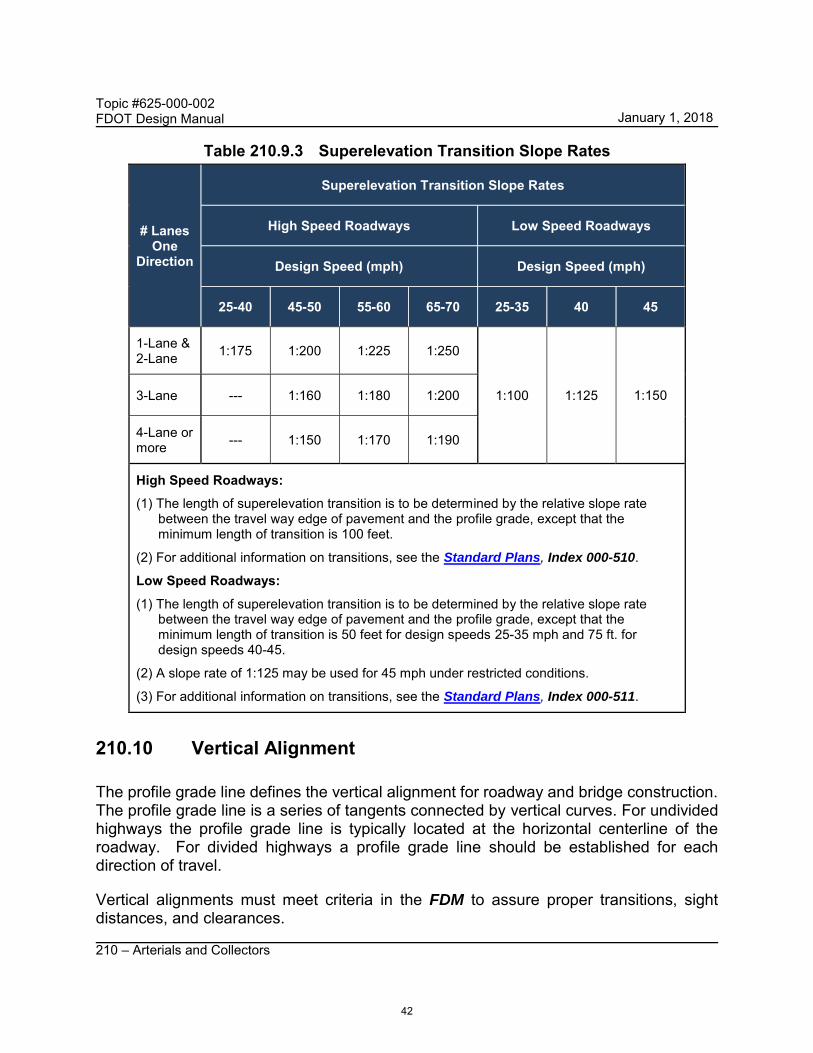
Table 210.9.3 Superelevation Transition Slope Rates
# Lanes One
Direction
Superelevation Transition Slope Rates
High Speed Roadways Low Speed Roadways
Design Speed (mph) Design Speed (mph)
25-40 45-50 55-60 65-70 25-35 40 45
1-Lane & 2-Lane 1:175 1:200 1:225 1:250
1:100 1:125 1:150 3-Lane --- 1:160 1:180 1:200
4-Lane or more --- 1:150 1:170 1:190
High Speed Roadways: (1) The length of superelevation transition is to be determined by the relative slope rate between the travel way edge of pavement and the profile grade, except that the
minimum length of transition is 100 feet.
(2) For additional information on transitions, see the Standard Plans, Index 000-510.
Low Speed Roadways: (1) The length of superelevation transition is to be determined by the relative slope rate
between the travel way edge of pavement and the profile grade, except that the minimum length of transition is 50 feet for design speeds 25-35 mph and 75 ft. for design speeds 40-45.
(2) A slope rate of 1:125 may be used for 45 mph under restricted conditions.
(3) For additional information on transitions, see the Standard Plans, Index 000-511.
210.10 Vertical Alignment
The profile grade line defines the vertical alignment for roadway and bridge construction. The profile grade line is a series of tangents connected by vertical curves. For undivided highways the profile grade line is typically located at the horizontal centerline of the roadway. For divided highways a profile grade line should be established for each direction of travel.
Vertical alignments must meet criteria in the FDM to assure proper transitions, sight distances, and clearances.
42
January 1, 2018

Topic #625-000-002 FDOT Design Manual
210 – Arterials and Collectors
210.10.1 Grades
The slope or grade of each tangent is expressed in percent rise (+) or fall (-); e.g., +2.000% or -2.000%. The maximum grades that may be used in establishing the vertical alignment is given in Table 210.10.1.
Table 210.10.1 Maximum Grades
Context Classification
Maximum Grades (percent)
Design Speed (mph)
25-30 35 40 45 50 55 60 65 70
C1 Natural C2 Rural N/A N/A N/A N/A 4 4 3 3 3
C2T Rural Town C3 Suburban C4 Urban General
8 7 7 6 6 5 N/A N/A N/A
C5 Urban Center C6 Urban Core 8 8 N/A N/A N/A N/A N/A N/A N/A
(1) Maximum grade used should not exceed 4% when truck volume ≥ 10% for all context classifications.
(2) For RRR projects, when existing grades do not meet the above requirements but meet the standards in effect at the time of construction, the existing grade may remain.
The point where tangents intersect is known as the vertical point of intersection (VPI). When two tangent grades intersect and no vertical curve is provided, the “kink” is known as the point of intersect (PI). The maximum change in grade (i.e., algebraic change) without a vertical curve is provided in Table 210.10.2.
Table 210.10.2 Maximum Change in Grade without Vertical Curve
Maximum Change In Grade Without Vertical Curve (percent)
Design Speed (mph)
25-30 35 40 45 50 55 60 65 70
1.00 0.90 0.80 0.70 0.60 0.50 0.40 0.30 0.20
43
January 1, 2018

Topic #625-000-002 FDOT Design Manual
210 – Arterials and Collectors
210.10.1.1 Curbed Roadway
The minimum distance between VPIs on curbed roadways is 250 feet. The minimum grade on curbed roadways is 0.30%.
210.10.2 Vertical Curves
A vertical curve must be provided when the change in grade of two intersecting tangent grades exceed the values shown in Table 210.10.2. A vertical curve is identified by a curve length (L) which is equal to the product of the K value (K) and the algebraic difference in grades (A).
Table 210.10.3 provides minimum K-Values, and Table 210.10.4 provides minimum vertical curve lengths.
Table 210.10.3 K Values for Vertical Curves
Minimum K Values For Curves
Design Speed (mph)
25 30 35 40 45 50 55 60 65 70
Sag 26 37 49 64 79 96 115 136 157 181
Crest (new const.) 19 31 47 70 98 136 185 245 313 401
Crest (RRR Criteria) 12 19 29 44 61 84 114 151 193 247
Length, L = KA Where: K = Rate of vertical curvature
L = Length of vertical curve, (feet)
A = Algebraic difference in grades, (percent)
(1) New Construction K values are based on an eye height of 3.5 feet and an object height of 6 inches. RRR Criteria K values are based on an eye height of 3.5 feet and an object height of 2 feet.
(2) The minimum curve length must not be less than values shown in Table 210.10.4.
44
January 1, 2018

Topic #625-000-002 FDOT Design Manual
210 – Arterials and Collectors
Table 210.10.4 Minimum Vertical Curve Lengths
Minimum Curve Length (feet)
Design Speed (mph)
25 30 35 40 45 50 55 60 65 70
Sag 75 90 105 120 135
200 250 300 350 400
Crest 300 350 400 450 500
210.10.2.1 RRR Criteria for Vertical Curves
Table 210.10.3 provides RRR Criteria K values to be used to check the sufficiency of existing crest vertical curves. 2011 AASHTO Green Book revised its K values to reflect a 2-foot object height; FDOT has not adopted this change for new construction but these K values can be used to check existing curves. An existing crest vertical curve that does not meet the minimum RRR Criteria K value requires a Design Exception or Design Variation to remain.
When crash data indicates that an evaluation is required, consider the following:
(1) The nature of potential hazards hidden by a hill crest. (2) The location of the hazard in relation to the portion of the highway where sight
distance falls below new construction criteria. (3) Effectiveness of other options such as relocating or correcting the hazard. (4) Providing warning signs.
Sag vertical curves do not typically pose stopping sight distance problems. A sag vertical curve that does not meet the minimum K value in Table 210.10.3 and does not have a crash history, does not require a Design Exception or Design Variation to remain.
210.10.3 Vertical Clearances
Consider the following vertical clearance requirements when developing the vertical alignment:
(1) Minimum clearances for bridge structures is given in FDM 260.6.
46
January 1, 2018
Topic #625-000-002 FDOT Design Manual
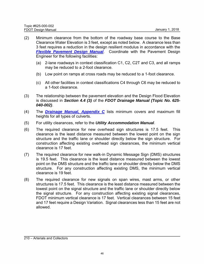
210 – Arterials and Collectors
(2) Minimum clearance from the bottom of the roadway base course to the Base Clearance Water Elevation is 3 feet, except as noted below. A clearance less than 3 feet requires a reduction in the design resilient modulus in accordance with the Flexible Pavement Design Manual. Coordinate with the Pavement Design Engineer for the following facilities: (a) 2-lane roadways in context classification C1, C2, C2T and C3, and all ramps
may be reduced to a 2-foot clearance. (b) Low point on ramps at cross roads may be reduced to a 1-foot clearance.
(c) All other facilities in context classifications C4 through C6 may be reduced to a 1-foot clearance.
(3) The relationship between the pavement elevation and the Design Flood Elevation is discussed in Section 4.4 (3) of the FDOT Drainage Manual (Topic No. 625-040-002).
(4) The Drainage Manual, Appendix C lists minimum covers and maximum fill heights for all types of culverts.
(5) For utility clearances, refer to the Utility Accommodation Manual. (6) The required clearance for new overhead sign structures is 17.5 feet. This
clearance is the least distance measured between the lowest point on the sign structure and the traffic lane or shoulder directly below the sign structure. For construction affecting existing overhead sign clearances, the minimum vertical clearance is 17 feet.
(7) The required clearance for new walk-in Dynamic Message Sign (DMS) structures is 19.5 feet. This clearance is the least distance measured between the lowest point on the DMS structure and the traffic lane or shoulder directly below the DMS structure. For any construction affecting existing DMS, the minimum vertical clearance is 19 feet.
(8) The required clearance for new signals on span wires, mast arms, or other structures is 17.5 feet. This clearance is the least distance measured between the lowest point on the signal structure and the traffic lane or shoulder directly below the signal structure. For any construction affecting existing signal clearances, FDOT minimum vertical clearance is 17 feet. Vertical clearances between 15 feet and 17 feet require a Design Variation. Signal clearances less than 15 feet are not allowed.
46
January 1, 2018
Topic #625-000-002 FDOT Design Manual
210 – Arterials and Collectors
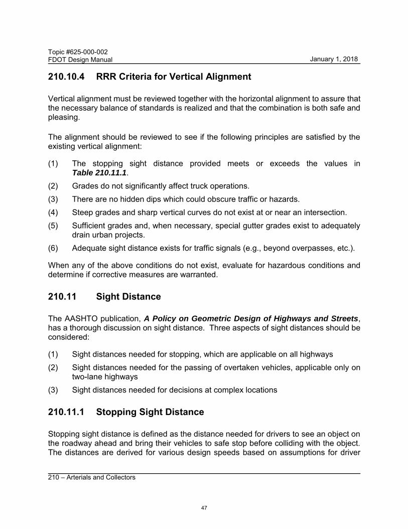
210.10.4 RRR Criteria for Vertical Alignment
Vertical alignment must be reviewed together with the horizontal alignment to assure that the necessary balance of standards is realized and that the combination is both safe and pleasing.
The alignment should be reviewed to see if the following principles are satisfied by the existing vertical alignment:
(1) The stopping sight distance provided meets or exceeds the values in Table 210.11.1.
(2) Grades do not significantly affect truck operations. (3) There are no hidden dips which could obscure traffic or hazards. (4) Steep grades and sharp vertical curves do not exist at or near an intersection. (5) Sufficient grades and, when necessary, special gutter grades exist to adequately
drain urban projects. (6) Adequate sight distance exists for traffic signals (e.g., beyond overpasses, etc.).
When any of the above conditions do not exist, evaluate for hazardous conditions and determine if corrective measures are warranted.
210.11 Sight Distance
The AASHTO publication, A Policy on Geometric Design of Highways and Streets, has a thorough discussion on sight distance. Three aspects of sight distances should be considered:
(1) Sight distances needed for stopping, which are applicable on all highways (2) Sight distances needed for the passing of overtaken vehicles, applicable only on
two-lane highways (3) Sight distances needed for decisions at complex locations
210.11.1 Stopping Sight Distance
Stopping sight distance is defined as the distance needed for drivers to see an object on the roadway ahead and bring their vehicles to safe stop before colliding with the object. The distances are derived for various design speeds based on assumptions for driver
47
January 1, 2018

Topic #625-000-002 FDOT Design Manual
210 – Arterials and Collectors
reaction time, the braking ability of most vehicles under wet pavement conditions, and the friction provided by most pavement surfaces.
Stopping sight distance is influenced by both vertical and horizontal alignment. A roadway designed to criteria employs a horizontal, vertical alignment, and a cross section that provides at least the minimum stopping sight distance through the entire facility.
Minimum sight distances are provided in Table 210.11.1.
Sight distances greater than shown in Table 210.11.1 should be considered when drivers require additional time to make decisions.
48
January 1, 2018

Topic #625-000-002 FDOT Design Manual
210 – Arterials and Collectors
Table 210.11.1 Minimum Stopping Sight Distance
Grade (percent)
Minimum Stopping Sight Distance (feet)
Design Speed (mph)
25 30 35 40 45 50 55 60 65 70
Dow
ngra
de
≤ 2 155 200 250 305 360 425 495 570 645 730
3 158 205 257 315 378 446 520 598 682 771
4 160 208 261 320 385 454 530 610 696 788
5 162 211 266 326 392 464 541 623 712 806
6 165 215 271 333 400 474 553 638 728 825
7 167 218 276 339 408 484 565 652 746 845
8 170 222 281 346 417 495 579 669 765 867
9 173 227 287 354 427 507 593 686 785 891
Upg
rade
≤ 2 155 200 250 305 360 425 495 570 645 730
3 147 190 237 289 344 405 469 538 612 690
4 146 188 234 285 339 399 462 530 602 678
5 144 186 231 281 335 393 456 522 593 668
6 143 184 229 278 331 388 450 515 584 658
7 142 182 226 275 327 383 443 508 576 648
8 141 180 224 272 323 379 438 501 568 639
9 139 179 222 269 320 375 433 495 561 631
210.11.2 Passing Sight Distance
Passing sight distance is the minimum distance that would enable a vehicle to pass another vehicle safely and comfortably, without interfering with oncoming vehicles traveling at the design speed. The minimum passing sight distance is sufficient for single or isolated passing only, and often opposing vehicles will cancel the passing opportunity.
49
January 1, 2018
Topic #625-000-002 FDOT Design Manual
210 – Arterials and Collectors
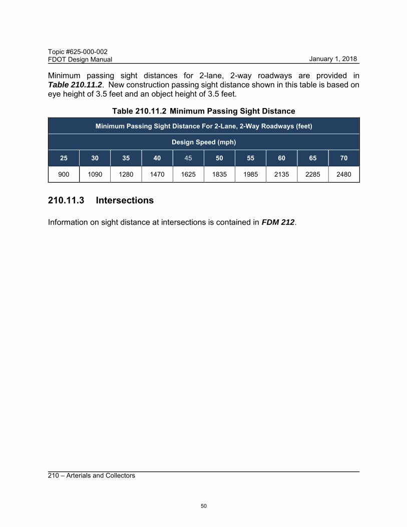
Minimum passing sight distances for 2-lane, 2-way roadways are provided in Table 210.11.2. New construction passing sight distance shown in this table is based on eye height of 3.5 feet and an object height of 3.5 feet.
Table 210.11.2 Minimum Passing Sight Distance
Minimum Passing Sight Distance For 2-Lane, 2-Way Roadways (feet)
Design Speed (mph)
25 30 35 40 45 50 55 60 65 70
900 1090 1280 1470 1625 1835 1985 2135 2285 2480
210.11.3 Intersections
Information on sight distance at intersections is contained in FDM 212.
50
January 1, 2018