UTG 1-67, South 1986 - IMESA · This document deals with the geometric design of urban arterials....
76
lSBN 0 7988 3988 0 Draft UTG 1, pp 1-67, Pretoria, South Africa, 1986
-
Upload
hoanghuong -
Category
Documents
-
view
216 -
download
3
Transcript of UTG 1-67, South 1986 - IMESA · This document deals with the geometric design of urban arterials....

lSBN 0 7988 3988 0
Draft UTG 1, pp 1-67, Pretoria, South Africa, 1986
Geonwtric design of urban arterial r-aads UTG 1, Pretoria, South Africa 1986
and research and have
To confirm their vali year period before r gestions for irn
The Secretary Committee of Ur
Geometric design of urban arterial roads UTG 1, Pretoria, South Africa 1986

This document deals with the geometric design of urban arterials. It forms part of a series on freeways, collectors and arterials.
Aspects covered in the document relate to basic design concepts and criteria. From these, guidelines in respect of horizontal and vertical alignment and cross- section are derived. The location and design of intersections is also discussed.
ie dokument handel oor die geornetriese ontwerp van stedelike verkeers- are. Dit vorm deel van 'n reeks wat handel oor deurpaaie en versamelare.
kte wat deur die dokurnent gedek word het betrekking op basiese ontwerp- pte en kriteria. Hieruit word riglyne rakende horisontaie en vertikale beiy- n dwarssnit, afgelei. Die ligging en ontwerp van kruisings word ook be-
Geometric design, urban arterials, horizontal alignment, vertical alignment, cross-section, intersections.
aft UTG was prepare for the @UTA Technical CO ittee on Geornetrics Leuw Cather and Associates Inc., un es of the National rt Commission and the epartment of
Geometric design of urban arterial roads UTG 1 , Pretoria, South Africa 1986
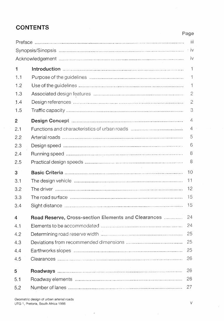
................................................................................................................ Preface
.............................................................................................. Synopsis/Sinopsis
.............................................................................................. Acknowledgement
Purpose of the el i nes ......................................................................
uidelines ...............................................................................
Associated design features ...................................................................
................................................................................... Design references
....................................................................................... Traffic capacity
Functions and c S ..............S........................
Arterial roads ............................................................................................
........................................................................................ Running speed
......................................................................... Practical design s eeds
................................................................................. The design ve i de
The driver ...............................................................................................
.................................................................................... The road sudace
........................................................................................ Sight distance
Elements to be ~axcc~brn .....................................................C.......
Determining road reserve idth . . . . . . .S. . .e. . . .
Deviations from reco it~et-rsions ..............=...............a...........
................................................................................. Earthworks slopes
............................................................................................. Clearances
................................................................................ oadway elements
..................................................................................... Number of lanes
Geometric design of urban arterial roads UTG 1. Pretoria. South Africa 1986
asic lane widths ................................................................................... ight and left-turn lanes .........................................................................
............................................................. ................... arking lanes ... Cross-fall ...... ... .................. .... ...........................................................
ffsets and channels ............................................................................ Shoulders ...............................................................................................
................................................................................................... ....................... efinition and measurement .........................,.S...... ...
Functions ..................... ... ....................................................................
Widths ....................................................................................................
.................................................................................................
irnensions ...........................................................................................
Median slope .........................................................................................
erbs ........................... ... ................................................................. penings in medians .............................................................................
ainted medians ........................ ... ...................................................
...................................................................................................
................................................................ apers to define turning lanes
........................................................... Tapers to narrow or merge lanes
................................................................ Tapers to widen or add a lane
................................................................... Tapers in turning roadways
................................. .................... apers in bus stop embayments .. em bayrnents ..............................................................
................................................ e
Minimum radius for horizontal curves and ses ., .,. .. . . .,. . ............... ..... .............................. Transition curves ... ..
uperelevation run-off ........................................................................
e widening ....................................................................................
t distance on horizontal curves .......................................................
eneral horizon al alignment controls ...................................................
cal alignment .................... .. ......................................................... Geometric design of urban arterial roads
UTG 1, Pretoria, South Africa I986

Gradients . ... ... . . . . . . . . . . . . . . . . . . . . * . . . , . , . . . . . . . . . . . . ,. . . . . . . . +, . . . . . . , . . . . . ..". * a m a n p * . - . B
Turning-roadway widths . . . . . . . . . . . ........* m * . a m m m a * m v v m . m m m o o m a m m
Ghannelization and traf S ....,. ... ..... .... .... .. ... .. . ..... ...... . .. ..... -... . . . . ,
ight and left-turn lanes ................... ~ ~ n m ~ ~ ~ n ~ u ~ ~ ~ s ~ ~ ~ ~ ~ ~ a D ~ ~ ~ ~ ~ ~ n ~ ~ ~ s n m ~ ~ ~ ~ D ~ ~ ~ m ~ ~ s ~ ~ ~ ~ e a ~
Radii at corners .. . . . . ... . . . . m -. a m m M m a m . a m a m m - . . *. a M R . -. v
Corner splays ...................a.msss . ~ ~ m . ~ . ~ . ~ s ~ e ~ ~ ~ ~ s . . s v e s s B . m e o s ~ ~ ~ ~ s ~ s . ~ s ~ s w s p s ~ s e .
Kerbs . .. . . . . . . . . . . . . . . . . . . ". % . m m e v m m m B m a m m a a a m v v a m . m a = a m a G v a
Movement-access functions . . .. . . . . . . . . . . . . . . m a a G m m . =. a =. a B m B a a a m . a
erelevation rates e(max) . . L C I s . . s s . n . s . . s D . . l . 3 D I s . S ..... j a . ~ ~ ~ ~ ~ ~ ~ ~ s ~ ~ ~ ~ ~ z s ~ s ~ p . ~ ~
Geometric design of urban arterial roads UTG 1, Pretoria, South Africa 1986

Shoulder sight distance for yield condition ............................................
.................... island offsets .. .............................................................. ............................ ................... Turn lanes : signalized intersections ...
ight-turn lanes : unsignalized ...................... .... ...,...........W.............
Typical left-turn designs ......................................................................
rterial with tapers at intersections with minor roads ..............W.............
Typical major intersection channelization slip road ...................S...........
.............................. Typical major intersection alternative configuration
.......................................................... Alternative left-turn configuration
.............................................................. Protected left-turn slip road
................................................... Slip road plus additional merging lane
..................................... Functions and characteristics for road classes
esign speeds for arterials ..................................................................
imensions of design vehicles ............................................................... ..................................... ..................................... Minimum turning radii ..
rake-force coefficients for various speeds ..........................................
......................... ................... topping sight distance on level roads .. ....................... .............................................. arrier sight distance ..
assing sight distance on level roads ...................................................
................... ................................................. ecision sight distance .. ane width and clearance between vehicles .......,...................S.............
ial facilities in verges ......................................................................
al widths of verge elements ...........................................................
........................................................................................ n widths
.................................................................. aper rates for active tapers
Taper rates for passive tapers .................................................................
Minimum radius for horizontal curves ....................................................
elationship of speed to maximum relative profile e
inimum va
ine two-lane roadway ....................................................... ................................................. lues of K for vertical curves
Geometric design of urban arter~al roads UTG 1, Pretoria, South Africa 1986

....................................................... fhs of vertical curves 44
. I -curvature relationshi s for in'tersectisns ................................... 52
n widths for se arate turning roadways of various ra ii ............... 53
ii at intersections .......................................................... 5'7
Geometric design of urban arterial roads UTG 1. Pretoria. South Africa 1986

The Committee of Urban Transport Authorities (CUTA) was formed in 1982 to provide a forum for discussion to promote coordination and, where appropriate, uniformity on technical standards for, and approaches to, the road and transp systems of urban areas in South Africa.
The various agencies responsible for the design of urban roads have been con- cerned for some time about the wide range of geometric design standar policies relating to the design of urban roads, not only between, but eve the various metropolitan areas. Particular problems can arise when a metropoi- itan route passes through several local authorities. Cases have arisen where a route passing through adjacent local authority areas has had a conspicuously different cross-section on either side of the boundary between the local authori- ties.
At the first meeting of CUTA in August 1982, it was decided to establish an Hoc Technical Committee on Geornetrics (AHTCG). This committee decid produce guidelines for the geometric design of urban roads with the foll objectives:
(1) to promote a uniform approach to the adoption of geometric design dards for urban roads;
(2) to recommend dimensions for geometric design elements to provi equate standards of safety and convenience on ur an roads under African conditions; and
(3) recognizing, that in the upgrading of urban roads and in the construction of new roads within built-up urban areas, restrictions in space so often prev the provision of geometric design elements to ideal dimensions, to prov guidelines for the adoption of reduced dimensions which would under prevailing circumstances still provide reasonable levels of safety and con- venience within economic, environmental, social and political constraints under South African conditions.
For ease of reference, a separate guidelines document will be produced for eae class of urban road.
Geometric design of urban arterial roads UTG 1, Pretoria, South Africa 1986
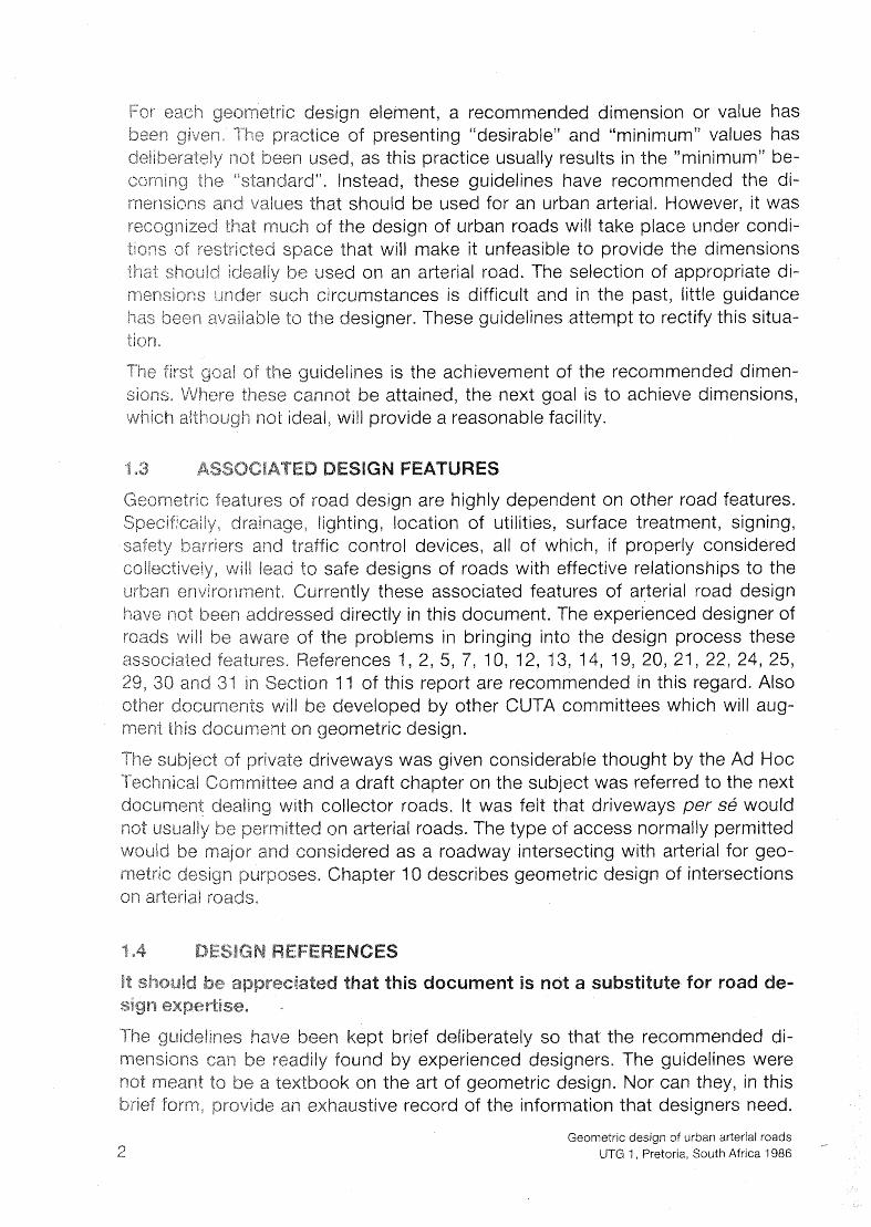
eometric design element, a recommended dimension or value has beeii given. The practice of presenting "desirable" and "minimum" values has deiiberatiiiy not been used, as this practice usually results in the "minimum" be- coming the "standard". Instead, these guidelines have recommended the di- msnsions and values that should be used for an urban arterial. However, it was recoyi?ized that much of the design of urban roads will take place under condi- tims rjf restricted space that will make it unfeasible to provide the dimensions that sl~c~i.;iu' ideally be used on an arterial road. The selection of appropriate di- mei?siccs i~nder such circumstances is difficult and in the past, little guidance has been avc3iiabie to the designer. These guidelines attempt to rectify this situa- tion,
The first goid of the uideljnes is the achievement of the recommended dimen- ese canrlot be attained, the next goal is to achieve dimensions, not ideal, will provide a reasonable facility.
Geometric features of road design are highly dependent on other road features. S-% specificaiiy: drainage, lighting, location of utilities, surface treatment, signing,
control devices, all of which, if properly considered esigns of roads with effective relationships to the these associated features of arterial road design
irectly in this document. The experienced designer of problems in bringing into the design process these nces 1 ,2 ,5 ,7 , 10, 12, 13, 14, 19,20,21,22,24,25,
of this report are recommended in this regard. Also veloped by other CUTA committees which will aug-
riveways was given considerable thought by the Ad Hoc d a draft chapter on the subject was referred to the next ollector roads. It was felt that driveways per se would n arterial roads. The type of access normally permitted
ered as a roadway intersecting with arterial for geo- hapter 10 describes geometric design of intersections
1-1 arterial roads.
en kept brief deliberately so that the recommended di- y found by experienced designers. The guidelines were ook on the art of geometric design. Nor can they, in this haustive record of the information that designers need.
Geometric design of urban arterial roads UTG 1, Pretoria, South Africa 1986

It is therefore important that the guidelines be supple by various sian- dard texts. The following texts were principal sources infornela.tion for these guidelines and are regarded as suitable references fo sign of urban arieriai roads:
AMERICAN ASSOCIATION OF STATE HlGHWA FICIALS. A Policy on Geometric Design of Hig DC, 1984, which is an updated combination of STATE HIGH WAY OFFICIALS. A Policy on Geomet
hington DC, MERIGAN ASSBCI TRANSPOR TlON OFFICIALS, A Poli
and Arterial Streets, Washington, DC, 1973.
NATIONAL INSTITUTE FOR TRANSPORT A Design of Rural Roads. Draft T R H 17, Pretoria
MATSON, T M, SMITH, W S and HURD, F ineen'ng. Ne%! York, McGraw-Hill, 1955.
PROVINCE OF THE CAPE OF GOOD HOP dated Reprint. Cape Town, Department of Roa
NATAL PROVINCIAL ADMINISTRATION. Geornee" Reprint. Pietermaritzburg, Natal Roads Department,
ORANGE f R STATE PROVINCIAL ADMlNl Handleiding. emfontein, Orange Free State
ClAL ADMINISTRATION. Typical Pretoria, Transvaal Roads Department, 1981.
NATIONAL TRA MISSION. Geometric toria, The Director General: Transport, Directorate: 1984.
SOUTH AFRICAN 1 STITUTE OF CIVIL ENGINEE and Design of To ship Roads and Stormwater nesburg, August 1981.
COUNCIL FOR SCIENTIFIC AND INDUSTRIAL Road Traffic Signs anual. 2nd edition, CSlR Manual
The traffic carrying capacity of arterial roads has not been dealt with in this re- port. Whereas it is recognized hat the geometry of a roa capacity it is noted that the analysis of tr fic capacity can intricate= The
Geometric design of urban arterial roads UTG l , Pretoria, South Africa 1986

er is referred to the 1965 Highway Capacity Manual, ated version, Ref. 2.
The road system can be classified into distinct classes of road based on the functions they have to perform. The main differences between classes of road relate to the extent to which they have to cater for movement or for access.
The classes of road can be listed in descending order of hierarchy as:
ncluding expressways)
Locals
1 the top end of the scale, freeways are dedicated to movement and have ac- cess limited to interchanges with grade separation of conflicting movements. At
e bottom of the scale the main function of local streets is to provide access to
Functions and characteristics for road classes
unction Locals Collectors Arterials Freeways
normal (km/h)
I . Traffic movement l
Secondary to Equal to Primary function of function of access property
access
low Interrupted Interrupted Uninterrupted conditions flow flow flow except
at intersec- tions and mid-block pedestrian crossings
40-90
Primary
Free-flow
Geometric design of urban arterial roads UTG 1 , Pretoria, South Africa 1986

ehicle types
access
3. Connections
4. Parking
rimarily passenger cars
rirnary considera- tion
Collectors, locals
Accepted
All types including buses
Equal to function of traffic movement
Arterials, collectors, locals
Accepted
All types including buses
Preferably excluded*
Freeways, arterials, collectors
Preferably excluded
Motor veh ides includin express buses
No access
Freeways, arterials
Source: Adapted from Ref. 3, Table A.5b, p.A.13.
* See Sections 1.3, 2.2, 2.5.
Table 2.1 summarizes the functions and characteristics of the various classes urban roads.
' ure 2.1 illustrates the c anging emphasis on movement and access for t ious classes of roa . The range covered in these uidelines is shown shad
uidelines for the gin eering Services in Residential To wns a useful table is provided which sets out the various terms used by diff authorities in South Africa, Unit nited States and scribe the various classes of ro
the movement of tra ic. More specific er distance movements in the urban s
erform its function satisfactorily an arterial road requires the follo '
vehicles inch
Geometric design of urban arterial roads UTG 1, Pretoria, South Africa 1986
n arterial road would normally be a divided road with two or three lanes in each irection.
rovision of the properties mentioned above would optimize the safety and traf- ic service of the arterial road system. Departures from these properties would
reduce safety and increase driver tension. Such departures should thus be made only when it is not physically or economically feasible to provide the re- quired characteristics to perform the arterial road function.
The concept of design speed developed by the American Association of State ighway and Transportation Officials ( SHTO) is used by many designers to
achieve a balanced design for a given roadway or roadway network. This is par- ticularly true for rural roads or for roads through lightly developed areas.
SWTO define speed as
the maximum safe speed that can be maintained over a specified section of hway where conditions are so favourable that the design features of the high-
ay govern. Ref. 7, p.60.
HT0 suggest that all pertinent features of a roadway should be related to a selected design speed in order to achieve a balanced design. They note that features such as curvature, superelevation and sight distance are directly related
and vary appreciably with, design speed. Other features, such as widths of vements and shoulders and clearances to walls and rails, are not considered
irectly related to design speed, but as they affect vehicle speed, higher ed for these features for higher design speeds. In concept assumes that when change is made in de-
sign speed, nearly all elements of the highway are subject to change. They go on to recommend that the design speed chosen should be consistent with the
d a driver is likely to expect. Ref. 7, pp. 60-61.
he need for a balanced design relates to the expectations of drivers and there- fore can vary considerably depending upon the functions of the road, the envi- ronment through which it passe and the posted or legal speed limit. Obviously,
need for a balanced design iminishes as the movement function and speed crease and the access function and density of development in the surround-
area increase. Thus there has been a tendency to establish design speeds ording to road type, that is, freeway, arterial and collector, and to try and bal-
ance the design throughout the length of roadway. However, in the past each type of road tended to have one design speed assigned to it regardless of envi- ronment, the restrictions caused by traffic control devices and the expected run-
ure 2.1 illustrates the varying degrees to which various types of r e movement and access. Ideally an arterial road sho
Geometric design of urban arterial roads UTG 1, Pretoria, South Africa 1986

UNRESTRICTED - ACCESS
.J
I d F WAY
INCREASING SPEED
Source : Adapted from Ref. 4, p. 121, and Ref. 5, p. 1 7 .
.1
Movement-Access Functions
access only to the extent of permitting intersections with oi tice, in urban areas, prevailing conditions often force than the ideal and the range of conditions shown in Fi results.
To employ appropriate geometric design standards, it is necess that the urban arterials for which designs will be re the ideal. The range of conditions applying to urban arterials ca shown in Table 2.2.
Geometric design of urban arterial roads UTG 1, Pretoria, South Africa 1986

The term "running speed" refers to the actual speed of a vehicle over a section of road. "Average running speed" is the arithmetic mean of the individual run-
speeds. Ref. 7, p. 68.
HT0 refer to running speeds being observed close to design speed for low eslgn speed curves and being well below design speed for high design speed
curves. Ref. 7, p. 69. Observations in South Africa have indicated that vehicles at or above design speed, even under wet weather conditions on curves igh design speeds. Ref. 8, p. 9.
e overall design concept, given practical considerations, is highly dependent on selection and understanding of the speed for which a road is to be designed. The design speed is influenced by three factors:
nction of the road ost of achieving geometric standards nvironment through which the road passes
ctuai standards employed may have to depart from the desired standards for he road's function if the cost of achieving them would be prohibitive. Urban de-
rs are often faced with traffic operating under unsafe and congested condi- If the cost of providing a relieving facility to ideal standards is unaffordable othing is done, traffic will continue to operate under the unsafe conditions.
ever, if compromise standards, which are better than existing, but low ideal, can be employed within the financial constraints then traffic an
safety conditions can be improved.
roads are designed for built-up areas, the speed desired in terms of the n may be inappropriate for the environment through which it passes. For le, in a built-up area, where access cannot be denied, here intersections sely spaced and where there is considerable pedestrian activity, high ould be unsafe, inappropriate and undesirable.
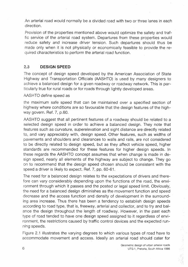
Thus, practical considerations may modify the desired design speed and geo- rds to be employed. An identification of the effect of prevailing expected or appropriate design speeds is given in Table 2.2 for
Geometric design of urban arterial roads UTG 1, Pretoria, South Africa 1986
A Design speeds for arte
Conditions prevailing
Expressway type. No property access. At-grade intersections spacing 2 500 m
No property access. At-grade intersections spacing 2 500 m No grade separated intersections
Property access unavoidable but limited t residential land use or infrequently from c developments. Intersection spacing 2 I00 m
Property access unavoidable from resi commercial land use. intersection spacing 3 100 m
Central area arterial street. Close intersection spacing with traffic signal control. Pedestrian activity.
Source: Adapted from Ref. 8, p. 14.
* The higher design speed should be used for preference.
an road authorities are faced with three distinct sets of fect the feasibility of achieving high design spee
ew construction in undeveloped areas New construction within existing built-up areas Improvements to old roads in built-up areas
hen road networks and lan there is usually scope for standards approac can often be located to provide geometric reasonable cost. Also the land use can be pl section spacing, to be appropriate to the spe
It-up areas, route location is hysical constr ints. The envir ned to suit the environment,
ronrnent is often unfeasible.
Geometric design of urban arterial roads UTG 1, Pretoria, South Africa 1986 9

improvement in geometrics of existing roads to achieve higher speeds is often even more restrained as the adjacent land use will have developed over the years in relation to the original design.
Practical considerations in urban areas therefore require adaptation of "ideal" standards to "practical" standards. Lowering of standards inevitably results in lower operating conditions in terms of comfort, convenience, safety and speed. As in all design considerations the trade-offs between the benefits and costs have to be assessed. Also, the implications of "doing nothing" rather than the ideal should be weighed against "doing something" even if not ideal.,
From their study of human factors in highway design and operations, Lunenfeld and Alexander concluded "Because drivers read the road and its information, and tend to believe what it appears to be telling them, a road that is substand- ard may not operate properly" and further that "Properly designed and operated facilities that take human factors into account generally operate safely and effi- ciently". Ref. 9, p.157.
in southern Africa, with population groups from the First World and the Third signers have to recognize the variety of skills at "reading" the road e road users. Consistent design standards are thus all the more impor-
tan%.
e basic criteria for road design are common for all types of roads as they re- late to typical characteristics of drivers and the performance of vehicles. The balance of this chapter is taken from Chapter 2, Basic Criteria, in TRH 17, Geo-
esign of Rural Roads. Ref. 10. The sections on passing sight distance sion sight distance were expanded with material from Geometric Stan-
ards for Canadian Roads and Streets. Ref. 1 1 , pp B1 6 - B1 9.
of the design vehicle, its dimensions and performance characteris- efore climbing lanes, maximum permissible grades, intersec-
tion layout and turning roadway radii and widths can be decided on. The driver's t above the road surface and his reaction time are used to derive stop- other sight distances. When these sight distances are known, rates of rvature can, in turn, be derived. The coefficient of friction of the roa
surface, in conjunction with the parameters relating to the driver, determines the rious sight distances, and also affects superelevation rates, from which mini- urn horizontal radii for the various design speeds are calculated.
rivation of the recommended values is given so that the designer dealing me other design vehicle of circumstance will be in a position to calculate
Geometric design of urban arter~al roads UTG 1 , Pretoria, South Africa 1986

The only South African design vehicle fo lished is the passenger car (P); the single Dimensions have been tentatively esiabli subject to review. Where dimensions are n American design vehicle have been a
The dimensions adopted for the various desi
Wheel- Vehicle bas
(m)
Passenger car D J Single unit Ref. 7, p 2 5 1,22
Single unit + trailer 6.7
Ref. 13, fig. 2-404.2A +3,
-P6,T
Single-unit bus Ref. 14, p 5 3 2,
Articulated bus Ref. 7, p.27 2,
+7,32
Semi-trailer Ref. 7, p.30 6 1 0,92 Q,61 -i-9,15
Source: Adapted from Ref. 10, Table 2.2.1
*Maximum in South Africa
lates are considered useful for est , and their use is rec it is further recomm ease of con-
Geometric design of urban arterial roads UTG 1, Pretoria, South Africa 1986

ruction, be approximated by simple or compound curves. igures 3.1 and 3.2 we dimensions for the construction of templates for single u ts plus trailers.
in In constructed situations where the templates are not appropriate, the capabili- ties of the design vehicle become critical. Minimum turning radii for the outer
e of the vehicle body are given in Table 3.2. It is stressed that these radii are ropriate only to cra:vl speeds.
Minimum turning radii
Vehicle Minimum turning
radius (m)
assenger car Ref. 12, p. l 0 le unit Ref. 7, p.25 le unit plus trailer Ref. 13, fig. 2-404.2A
Single-unit bus Ref. 14, p.53 (updated) iculated bus Ref. 7, p.27
emi-trailer Ref. 7, p 3 0
Source: Adapted from Ref. 10, Table 2.2.3
*Adjusted 0,50 m for body overhang
e rious grades have been the subject of much study under ions, and it has been found that performance is not signifi-
antly affected by height above sea-level. Performance can therefore be rep- resented by a single family of curves as shown in Figure 3.3. Ref. 15, p.345 Ref.
mass to power ratio of 275 kg/ has been used as representative of the Percentile of South African tru , That is, 15 per cent of trucks have a
higher mass to power ratio and are not accommodated by the curves in Figure 3.3.
cent of passenger car drivers have an eye t at or above per cent of truck drivers an eye height of or more. These values have accordingly been adopted for use in these
lines. Ref. 17 an
Geometric design of urban arterial roads UTG 1, Pretoria, South Africa 1986

A figure of 2,5 seconds has been generally ad sponse to a single stimulus. American practice tion time of 5,7 to 10,O seconds for more co where more than one external circumstance m u s t b appropriate response selected and initiated.
where
L = Wneelbase of datstgn vehicle
I I W T = Track width
WL = Through tone width
R K = Kerb radlus
R i f f = Inner rear !rock rodIus
R o F Outer front track rodius
OH = Front O v e r h a n ~
PASSENGER CAR
SINGLE U N I T TRUCK
BUS
Source : A d a p t e d from Ref.10, F i g 2,2,2(a)
.l
Wheel Tracks of Rigid Chassis Vehicles
Geometric design of urban arterial roads UTG 1, Pretoria, South Africa 1986

w h e r
L l L: \B$lhe$Ob~~e o f t rac tor
L 2 Wheelbase of semitrai ler
W T = Track w i d t h
WL = T h ~ o u g h lane! width
R T l C U l A f EO BUS
Dimensions in m e t r e s
* a L = Measured t o f r on f w h e e l s o f t r a i l e r
S o u r c e : Adapted from Ref. 10, F i g . 2 . 2 . 2 ( b )
Geometric design of urban arterial roads U I G 1, Pretoria, South Africa 1986
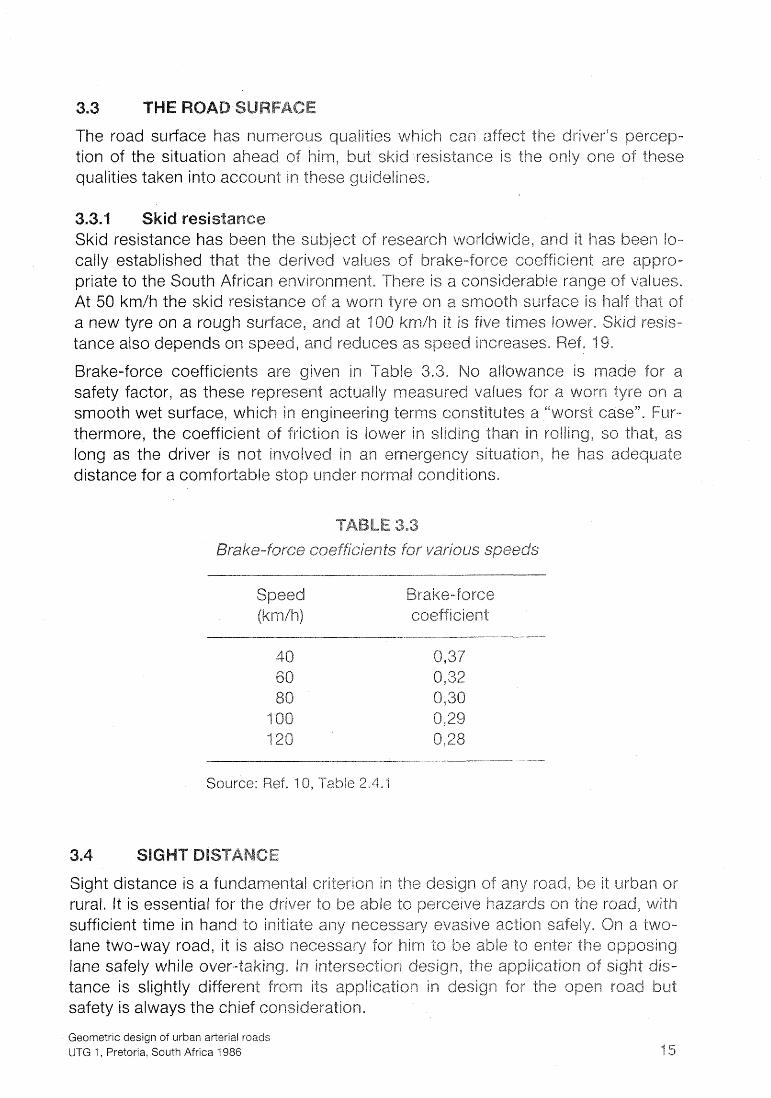
The road surface has numerous qualities ich can affect $h river's perce tion of the situation head of him, but ski esistance is the only one of the qualities taken into account in t
subject of research worl brake-force coeffici
nt, There is a consi
Brake-force coefficients svvance is re-ra safety factor, as these re ualiy measured values for a worn tyre on smooth wet surface, whi es a " W O ~ S % case". Fur- thermore, the coefficien long as the driver is not involved in distance for a comforts
coefficient
Source: Ref. 10, 'Table 2.4.1
Sight distance is a fun mental criterion in the deslyn of any road, he it urban or rural. It is essential for river to be abie to perceiv s on the road, with sufficient time in hand itiate any necessary evasi lane two-way road, it is also necessary for him to be able to e lane safely while over-takin tion design, the application of sight dis- tance is slightly diff !cation in desi safety is always the
Geometric design of urban arterial roads UTG 1, Pretoria, South Africa 1986

Source : Ref. 10, F i g . 2 . 2 . 4 . Adapted from Ref. 15, ~ i g s . 4 and
-------..I---
Tr~sck Speeds on Grade
Geometric design of urban arterial roads UTG 1, Pretoria, South Africa 1986

his vehicle saf to a standstill, and is thus bas e and skid resis-a tance. The total distance trav two components:
the distance covered during the driver's r the distance required to decelerate to 0 k
The stopping distance is expressed as
s = 0,7v + v2/254f where S = total distance travelled (m)
v = speed (km/h) f = brake-force coefficient
Stopping sight distances for a range o force coefficients are given in Table 3.4.
Stopping sight distance on le
Design speed V
(km/h) (km/h) p-
40 40 45 50 50 65 60 58 70 64 80 72 90 7
100 85 110 120
Source: Adapted from Ref. 10, Table 2.5.1 and Ref. '7, p. 138.
Stopping sight distance is measured from an eye height o "1,135 m to an o height of 0,15 m. This object height is used cause an obstacl height would not normally represent a into account because measuring the si istance to the road substantially increase the length of the vertical curve an required.
The values of stopping sight distance given in P 3.4 are similar $0 the range of design values given in has related to this lower range.
Geometric design of urban arterial roads UTG 1, Pretoria, South Africa 1986
Geometric design of ~ ~ r b a n arterial roads UTG 1 , Pretoria, South Africa 1986
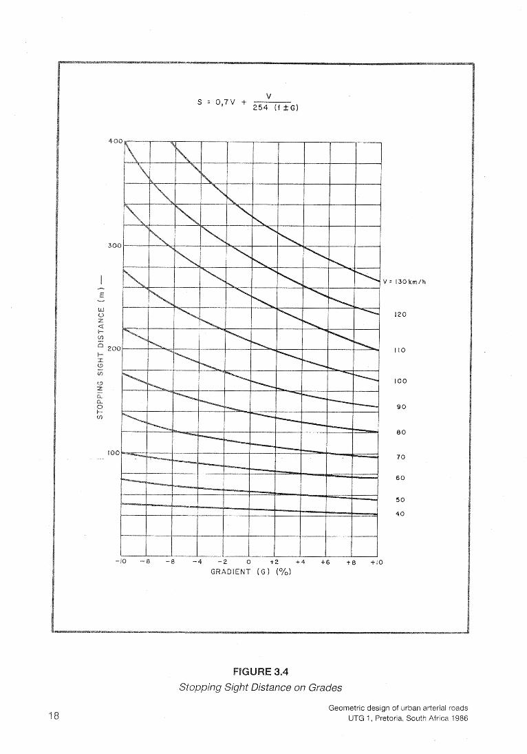
The gradient has a marked effect on the stopping Gradient (G) modifies the stopping sight distance for
S = 0,7v + v2/254(f t G) Ref. 7, p. 143.
where G is the per cent of grade divided by 100.
AASHTO, Ref. 7, p.143, assume v equal to design speed for do tions and v equal to a running speed which is less than desig grade conditions. Similarly, TRH 17, Geometric Des i~n of Rural values of stopping sight distance on grades with built-in assurn ing operating speed being less than design speed when roa Ref. 10, Fig. 2.5.1 (a).
Figure 3.4 is a direct graphical representation of the for sight distance on grades between -10 per cent and + speeds v between 40 km/h and 130 krn/h.
Stopping sight distance can also be affected by a visual o struction (such cutslope or a wall) next to the carriageway on the inside of a horizontal shown in Figure 3.5.
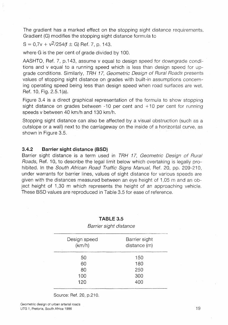
ie! ce Barrier sight distance is a term used in TRH 17, Geometric De Roads, Ref. 10, to describe the legal limit below hibited. In the South African Road Traffic Signs under warrants for barrier lines, values of sight distance for vario given with the distances measured between an eye height of 1,05 ject height of 1,30 m which represents the height of an ap These BSD values are reproduced in Table 3.5 for ease of reference.
A Barrier sight distance
Design speed (km/h)
Barrier sight
Source: Ref. 20, p.210.
Geometric design of urban arterial roads UTG l , Pretoria, South Africa 1986

CENTRE LINE OF I NEAREST LANE
Horizontal Radius for Stopping Sight Distance
Geometric design of urban arterial roads UTG 1, Pretoria, South Africa 1986

C
ed arterial roa for an extend
initial period.
Passing sight distance for use in design is determined o needed to safely complete normal passing manoeuvres. casions to consider multiple passings, where two or more vehicles pass or are passed, it is not practical to assume such conditions in devel standards. Instead, sight distance is determined for a s single vehicle. Longer sight distances occur in design a accommodate an occasional multiple passing.
Standard minimum passing sight distance values are Table 3.6 for a range of design speeds from 50 km/h tant, for reasons of safety and service, to provide as m as possible in each section of road. The designer shou is no long stretch where passing is not possible. The a distance available on a section of road has considera age speed of the traffic. This is particularly true wher capacity. The economic effects of reduced speeds c mined at the present time, but there is no doubt that erable when able to operate at or near the design sp ence from other vehicles. The designer should consi when setting vertical alignment.
Passing sight distance on level roads
Design speed Passing sight (km/h) distance (m)
Source: Ref. 1 1 , Table 8.2.4, p.BI8. Ref. 10, Table 2.5.4.
ef. 11, Table ef. l Q, Table 2.5.4.
Geometric design of urban arterial roads UTG 1, Pretoria, South Africa 1986

3. e Stopping sight distances are usually sufficient to allow reasonably competent and alert drivers to come to a hurried stop under ordinary circumstances. How- ever, these distances are often inadequate when drivers must make complex or instantaneous decisions, when information is difficult to perceive, or when unex- pected or unusual manoeuvres are required. Limiting sight distances to those
rovided for stopping may also preclude drivers from performing evasive ma- oeuvres, which are o f tm less hazardous and otherwise preferable to stopping. ven with an appropriate complement of standard traffic control devices, stop-
ping sight distances may not provide sufficient visibility distances for drivers to corroborate advance warnings and to perform the necessary manoeuvres. It is evident that there are many locations where it would be prudent to provide longer sight distances. In these circumstances, decision sight distance provides the greater length that drivers need.
cision sight distance is the distance required for a driver to detect an infor- mation source or hazard which is difficult to perceive in a roadway environment that might be visually cluttered, recognize the hazard or its threat potential, se- lect appropriate action and complete the manoeuvre safely and efficiently. Be- cause decision sight distance gives drivers additional margin for error and af- fords them sufficient length to manoeuvre their vehicles at the same or reduced speed rather than to just stop, its values are substantially greater than stopping
rivers need decision sight distances whenever there is a likelihood for error in either information reception, decision making, or control actions. Examples of
itical locations where these kinds of errors are likely to occur, and where it is irable to provide decision sight distance are: interchanges and intersections;
locations where unusual or unexpected manoeuvres are required; changes in cross-section such as toll plazas and lane drops, and areas of concentrated de-
and where sources of information compete, for example from roadway ele- ents, traffic, traffic control devices, and advertising.
ecision sight distances in Table 3.7 provide values to be used by designers for approriate sight distances at critical locations and serve as criteria in evalua-
the suitability of the sight lengths at these locations. Because of the ad- nal safety and manoeuvrability these lengths yield, it is recommended that
decision sight distances be provided at critical locations or that these points be relocated to locations where dec ion sight distance lengths are available. If it is ot feasible to provide these dis nces because of horizontal or vertical curva-
ture or if relocation is not possible, then special attention should be given to the se of suitable traffic control devices for providing advance warning of the con- iiions that are likely to be encountered.
e of decision sight distance values that will be applicable to most situa- as been developed. The range recognizes the variation in complexity that
Geometric design of urban arterial roads UTG 1, Pretoria, South Africa 1986
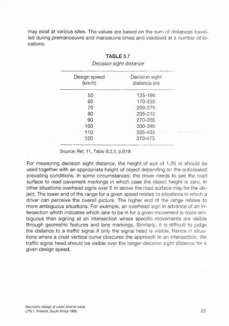
may exist at various sites. The values led during prernanoeuvre and manoeuvre times and v cations.
Decision sight distance
Design speed (krnh) distance (m)
Source: Ref. l l , Table
For measuring decision sight distance, the height o used together with an appropriate height of object d prevailing conditions. In some circumstances, the d surface to read pavement marki other situations overhead si ject. The lower end of the r driver can perceive the o more ambiguous situation tersection which indicates which lane to be in for biguous than S ning at an intersection where through georne c features and lane markings. the distance to a traffic signal if only the signal tions where a crest vertical curve obscures the traffic signal head should be visible over the longer decision sight distance for a given design speed.
Geometric design of urban arterial roads UTG 1, Pretoria, South Africa 1986

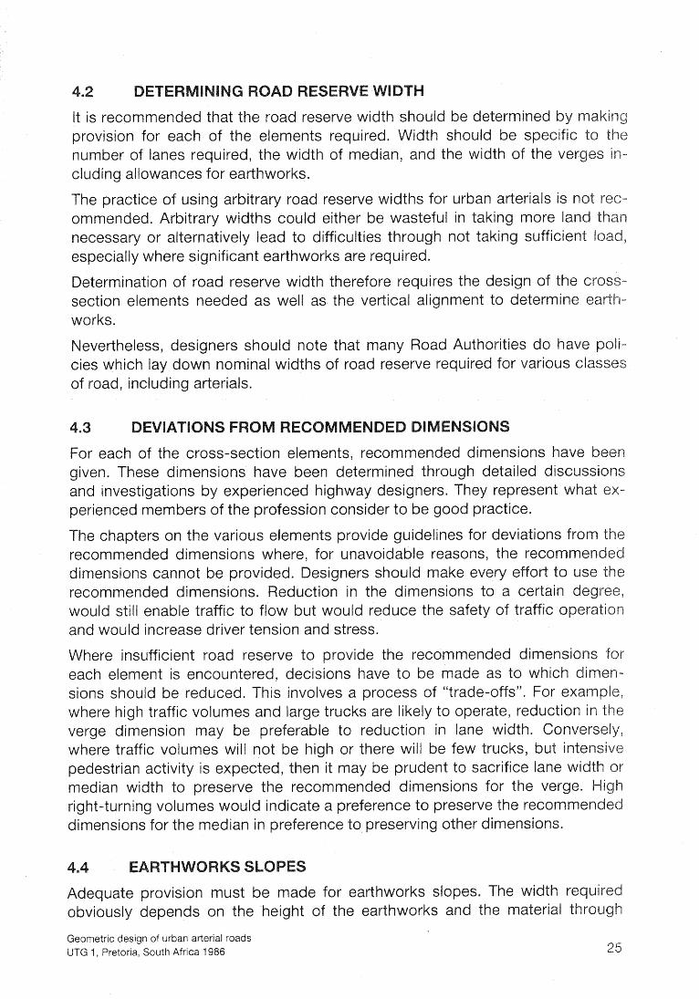
'Three basic components of the cross-section of an arterial have to be accom- modated with the road reserve as shown in Fig 4.1. These are:
5" The roadways (carriageways)
in the case of a dual roadway
These components are discussed in detail in Chapters 5, 6 and 7. ->
!he roadway includes all the cross-section elements between the faces of the kerbs on either side. The principal variables accounting for the width of roadway are the number of lanes and the width of lane used, The actual number of lanes to be s~lpplied depends on the projected traffic volumes. The most common roadways required for urban arterials are two or three lanes in each direction.
areas on either side of the road include all the elements from the face to the property boundaries (edges of the road reserve). An element of
which could have a significant effect on road reserve widths is the or earthworks and this will vary from road to road.
n separates the two roadways and is measured from kerb face to rincipal variables affecting the width of the median are:
he right-turn lane usually included in the median of the nose alongside the right-turn lane ion far future lanes
Road Reserve Components
Geometric design of urban arterial roads UTG 1, Pretoria, South Africa 1986
It is recommended that the road reserve width should be determined by maki provision for each of the elements required. Width should be specific to the number of lanes required, the width of median, and the width of the verges in- cluding allowances for earthworks.
The practice of using arbitrary road reserve widths for urban arterials is not rec- ommended. Arbitrary widths could either be wasteful in taking more land t necessary or alternatively lea to difficulties through not taking sufficient I especially where significant earthworks are required.
Determination of road reserve width therefore requires the design of the cross- section elements needed as well as the vertical alignment to determine earth- works.
Nevertheless, designers should note that many Road Authorities do have cies which lay down nominal widths of road reserve required for various classes of road, including arterials.
For each of the cross-section elements, recommended dimensions have b given. These dimensions have been determined through detailed discussi and investigations by experienced highway designers. They represent what ex- perienced members of the profession consider to be good practice.
The chapters on the various elements provide guidelines for deviations from the recommended dimensions where, for unavoidable reasons, the recomme dimensions cannot be provi d. Designers should make every effort to us recommended dimensions. duction in the dimensions to a certain de would still enable traffic to flow but would reduce the safety of traffic o and would increase driver tension and stress.
Where insufficient road reserve to provide the recommended dimensions for each element is encountered, decisions have to be made as to which dime sions should be reduced. This involves a process of "trade-offs". For example, where high traffic volumes and large trucks are likely to operate, reduction in the verge dimension may be preferable to reduction in lane width. Conversely, where traffic volumes will not be high or there will be few trucks, but int pedestrian activity is expected, then it may be prudent to sacrifice lane W
median width to preserve the recommended dimensions for the verge. Hi right-turning volumes would in icate a preference to preserve the recomm dimensions for the median in preference to preserving other dimensions.
e provision must be made for earthworks slopes. The width required obviously de ends on the hei ht of the earthworks and the material throu
Geometric design of urban arterial roads UTG 1, Pretoria, South Africa 1986
which cuts are being made or which is being compacted to form embankments.
nominal road reserve may be used to accommodate the roadways, median nominal verges. Local widenings of the reserve can be made to accom- ate earthworks which would encroach beyond the nominal road reserve.
arious local authorities have established techniques for acquiring this ad- itional road reserve, for example, as a servitude. The property owner is thus
able to use the servitude area in calculations to establish the permissible floor area that can be constructed on the property.
The standard minimum vertical clearance from any point in a roadway to an overhead structure is 5,1 m. If the structure is light such as a pedestrian over-
ass, then the vertical clearance required is 5,5 m or more.
uture overlays must be taken into account when determining clearances.
Many special circumstances require specific vertical clearances either above or elsw the road surface. These clearances have to be determined in consultation ith the appropriate authority. For example, when a road passes under a high
voltage line, special clearances are necessary under the Machinery and Occupa- i Safety Act, 1983, No 6, 1983, Ref. 21. Similarly, special clearances relate
to railways and trolley bus routes and pipelines.
verhead traffic signs require a clearance of 5,2 m. Ref. 20.
uate horizontal clearance should be provided. A 2 m clear verge alongside uter kerb is recommended. igid structures should be placed at least 2 m of the roadway.
ay is defined as the area available for vehicle movement between the e case of an undivided road the kerb would separate the roadway
es on either si . For a divided road, on one side t oadway from verge area and on the other side
th of roadways is measured from the bottom of the face of the kerb to f face of kerb a
Geometric design of urban arterial roads UTG 1, Pretoria, South Africa 1986
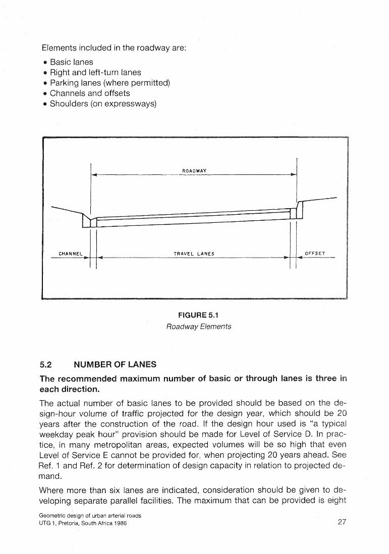
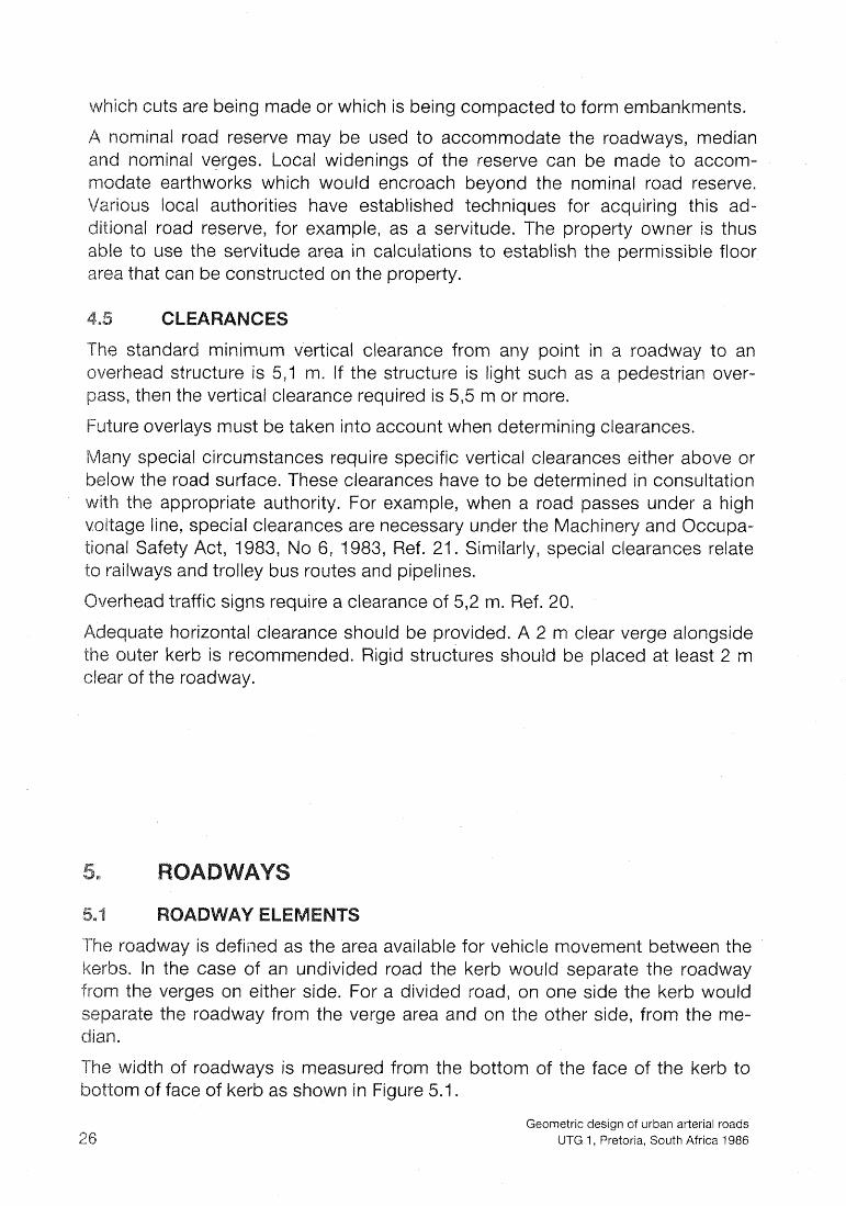
Elements included in the roadway are:
Basic lanes Right and left-turn lanes
a Parking lanes ( here permitted) o Channels and offsets
Shou'lders (on expressways)
Roadway Elements
The actual number of basic lanes to be provided should be based on t n-hour volume of traffic pr jected for the esign year, which should be 2 rs after the construction the road. If t design hour used is "a
ur" provision should e made for Level of tice, in many metro ted volumes will be so high th
r: when projecting 20 years ahe ign capacity in relation to proje
rnand.
Where more than six lanes are indicate arate parallel facili
Geometric design of urban arterial roads UTG 1, Pretoria, South Africa 1986

asic lanes, and this should only be resorted to in exceptional circumstances. hen eight lanes are used, separate right-turn phases in the traffic signals are
normally required for safety reasons.
F e in S
Two-lane arterials are unusual as permanent facilities. However, two-lane arteri- als may have frequent application as the first stage of a four-lane arterial. Where an arterial road is located in a corridor, in which traffic generation requiring more than two lanes cannot be conceived, it may be appropriate to provide two lanes only. Widening should be provided at intersections to include right-turn lanes.
n steep gradients an auxiliary climbing lane should be considered.
m
ane width is measured from the centre of the lane line to the centre of the adja- cent lane line for inside lanes and to the edge of the channel or to the edge of the concrete offset from the kerb in the case of a kerbside lane.
uction below 3,4 m would still permit traffic operation but with increased driver tension and more potential for side-swipe accidents and for collisions with roadside fixed objects.
e widths have to be sufficient to accommodate the widths of the design ides and provide clearance between vehicles and, in the case of kerbside S, clearance to kerbside objects. An appropriate vehicle-to-vehicle clear- for vehicles travelling in the same direction is 1,2 m. Ref. 22, p.4.
le 5.1 shows the clearances provided by a range of practical lane widths for us combinations of design vehicles.
Lane width and clearance between vehicles
Lane width (m)
Vehicle ty Pes
Clearance (m)
3,o car to car 1 2 car to truck 0,8 truck to truck 0 3
3,4 car to car 196 car to truck 1 2 truck to truc 0 3
car to car car to truck truck to truck
Geometric design of urban arterial roads UTG 1, Pretoria, South Africa 1986

This section refers to right and left-turn lanes which are adjacent to arated, from basic lanes. Separate turning roadways are describ 10.5.
Where significant volumes of trucks are expected to be turning, the turning lan should be increased to 3,4 m or more in association with a 3,4 m adjacent lane and a 0,3 m offset from kerb. This would permit a 1,2 m vehicle-to-vehicle cle ance between a turning truck and a through-moving car as well as a 0, ance to the bottom of the kerb.
The absolute minimum width of 2,7 m should be resorted to in traffic m ment improvements where insistence on the 3,O m width would mean t turning lane could not be provided.
Where a new road has to be built in areas where on-street parkin and cannot be eliminated, however undesirable, it may be necessa a parking lane. In these circumstances the parking lane should ha width as the basic through lanes, so that it can be used for rnovin peak periods in association with parking prohibition. Details of on-s are given in Parking Standards. Ref. 12.
In areas of intense rainfall, steeper cross-falls may be necessary to facilit drainage. The cross-fall may be increased to 2,5 per cent in such cases.
Where roadways have four basic lanes, the cross-fall should be increas per cent across the whole r alternatively consideration may to a central crown (camber
In areas of steep cross-slope, it may be economical and appropria the cross-fall of the two carriageways in the same direction as the In such cases the cross-fall on one roadway would be towards the significant discomfort is experienced by motorists on 2 or 3 per cent cross-fail
rds the right-hand side instead of towards the left-hand side r these circumstances the cross-fall should not excee
Geometric design of urban arterial roads UTG 1, Pretoria, South Africa 1986

offset is provided either by a drainage channel or, where no channel is ed, by a 0,3 m offset between the kerb and edge of lane.
Provision for emergency stopping can be made by means of a 2 m clear verge ith mountable kerbs facilitating movement onto it from the roadway.
ge of an arterial road is the area between the roadway and the road re- oundary. Its width is measured from the bottom of the face of kerb or,
where no kerb exists, from the edge of hardened surface (edge of roadway) to reserve boundary (property line).
rime function of arterial roads is the movement of vehicles. The prime e of an arterial road is to provide horizontal clearance to en- smooth flow of vehicles in the roadway. The verge is also a
uffer zone between the roadway and adjacent property and therefore may in- clude landscaping, visual screens and sound barriers. Due to the location and continuity of arterial roads in the urban framework they are often required to serve other functions and include special facilities in the verges as indicated in
Geometric design of urban arterial roads UTG 1, Pretoria, South Africa 1986
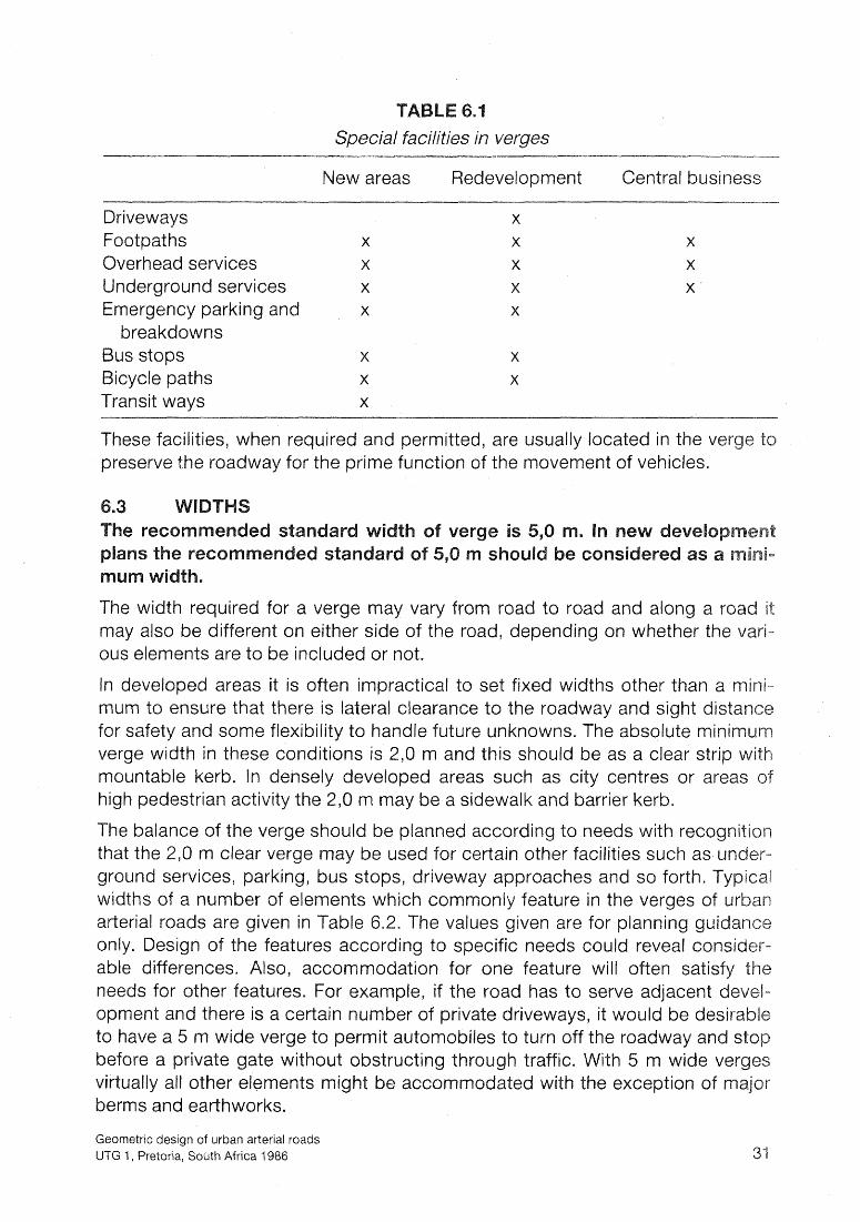
Special facilities in verges
New areas Redevelopment Central busines
Driveways Footpaths Overhead services Underground services
Bicycle paths Transit ways
These facilities, when required and permitted, are usually located in the ver preserve the roadway for the prime function of the movement of vehicles.
The width required for a verge may vary from road to road and along a roa may also be different on either side of the road, depending on whether the vari- ous elements are to be included or not.
In developed areas it is often impractical to set fixed widths other than a rnini- mum to ensure that there is lateral clearance to the roadway and sight dis for safety and some flexibility to handle future unknow S. The absolute rnin verge width in these conditio S is 2,O m an this should be as a clear strip with mountable kerb. In densely eveloped are s such as city centres or areas of high pedestrian activity the 2,O m may be a sidewalk and barrier kerb.
The balance of the be planned according to needs with reco that the 2,O m clea e used for certain other facilities such as ground services, p stops, driveway approaches and so forth. widths of a number of elements which commonly feature in the verges o arterial roads are given in Table 6.2. The values given are for planning g only. Design of the features according to specific needs could reveal c able differences. Also, accommodation for one feature will often satisfy t needs for other features. For example, if the road has to serve adjace opment and there is a certain number of private driveways, it ould be desk to have a 5 m wide verge to permit automobiles to turn off the roadway
ate without ob lernents might
Geometric design of urban arterial roads UTG 1, Pretoria, South Africa 1986

Typical widths of verge elements
erb, semi-mountable
riveway approaches rench width for underground service, minimum
s stop embayment
VERGE ": "p*
POLES
Verge Elernen ts
Geometric design of urban arterial roads UTG 1, Pretoria, South Africa l986

The 5,O m width of median is predicated on the basis of providing 3,Q right-turn lane at intersections, together with a residual width of 2,0 m median at the nose and an offset of 0,3 m between the turning lane
The 2,O m width alongside the right-turn lane is recommended to provid for pedestrians crossing the road, one carriageway at a time. The width for a kerbed median alongside the right-turn lane is 1,2 m. Thi necessary for visibility of the island, to accommodate road traffic sign the "keep left" sign and to accommodate stormwater kerb-inlets cases, such as on superelevated curves.
Table 7.1 below shows the functions served by various widths of median.
Median widths
Function (m)
Provision of right-turn lane and pedestrian refuge. (Recommended normal design)
Provision of right turn with painted barrier line with no pedestrian refuge. (Should be used only in exceptional circumstances) 3*
Separation of opposing traffic. (Should be used only on long sections without intersections where sufficient width cannot be obtained for full medians) 1 3
Full median with provision for an extra lane in each direction 11,
It is usually inadvisable to reduce the me ian width to 1,5 m between intersec- tions because of the abru hanges in alignment li ely to result when wi the median to aacommod he right-turn lane and then narro the intersection. However re there are long sections of ro sections and space is at rniurn, consideration coul be given to the nar-
he transitions from t e full median coul
Geometric design of urban arterial roads UTG 1, Pretoria, South Africa 1986

here the prevailing cross slope requires the roadways on either side of the me- ian to be at different elevations, additional width may be necessary to keep the
median cross-fall to a maximum of 25 per cent.
rovision of public transport facilities such as busways or light-rail transit lines uires special treatment specific to the type of transit and the circumstances
at the location. Details requiring solutions are, among others, the accommoda- tion of the right-turn movement across the transit lanes and passenger movements as pedestrians when boarding and alighting.
solute maximum slope should be 25 per cent and this should be used small differences in elevation.
t existing and proposed intersections care must be taken to ensure that vehi- cles crossing the arterial are not subjected to severe changes in profile.
mi-mountable kerbs deter vehicles from crossing the median but do not ysically prevent em. By the same token they are not likely to cause vehicles
ounting them ina ertantly to go out of control.
rrier kerbs offer more deterrence to vehicles, but also cannot physically pre- vehicles crossing. They are more likely to cause a vehicle striking them to
out of control.
estrian crossings, ramps should be provided for prams and wheelchairs.
medians reduce the number of serious head-on collisions and deter rivers from making dan erous right-turn movements into midblock driveways.
S may be used instead of kerbed medians when insufficient eet the minimum sizes and widths of island. When insuffi-
vide a nose of 1,2 m width alongsi S should be m
ith the requirements of ad Traffic Sig
medians is, however, poor in wet weather.
Geometric design c? urban arterial roads UTG 1, Pretoria, South Africa 1986

There are two basic types of taper, each with different geometric require in various circumstances:
An "active taper" causes lateral transition of traffic. A "passive taper" allows lateral transition of traffic.
Active tapers are used to narrow a roadway or a lane, or to merge two lanes into one.
Passive tapers are used to widen a roadway or a lane, or to add a lane.
In general, active tapers should be long, and passive tapers may be short.
Tapers are also used in higher type intersections to lead into and out of turni roadways. Similarly, tapers are used at the ends of embayments for bus sto and for parking.
With reference to igure 8.1, a typical right-turn lane requires a passive from the right e ge of the through lane to the right ed e of the turning lane. I h i taper is normall at a rate of 1 in 10. For a 3 m wide t ning lane the length of ta- per would be 30 m. However, in urban conditions the need for storage len the turning lane often outwei hs the need for a smooth transition and the rate can be reduced 1 in 2. When traffic is light and speeds are high th sition can be done in e storage lane. When traffic is heavy and speeds a the 1 in 2 taper will allow 4 to 5 additional cars to queue for the turn. T lessen the chance of vehicles at the tail of the queue blocking through traffic.
If a median has to be created or widened to "shadow" the right-turn lane an active taper will be require on the approach. Rates of ta condition are given in Table 8.1 which is derived from Table RMC in the African Road Traffic Signs Manual. Ref. 20, p.224.
The taper rates associated with painted lines in Table 8.1 are preferred for all applications. The rates associated with kerbs are minimum rates and the should be clearly visible and highlighted with paint or markers.
These tapers are active and the rates given in Ta le 8.1 are appropriate. the more gradual taper rates associated with painted line tapers are preferre all applications.
Geometric design of urban arterial roads UTG 1, Pretoria, South Africa 1986
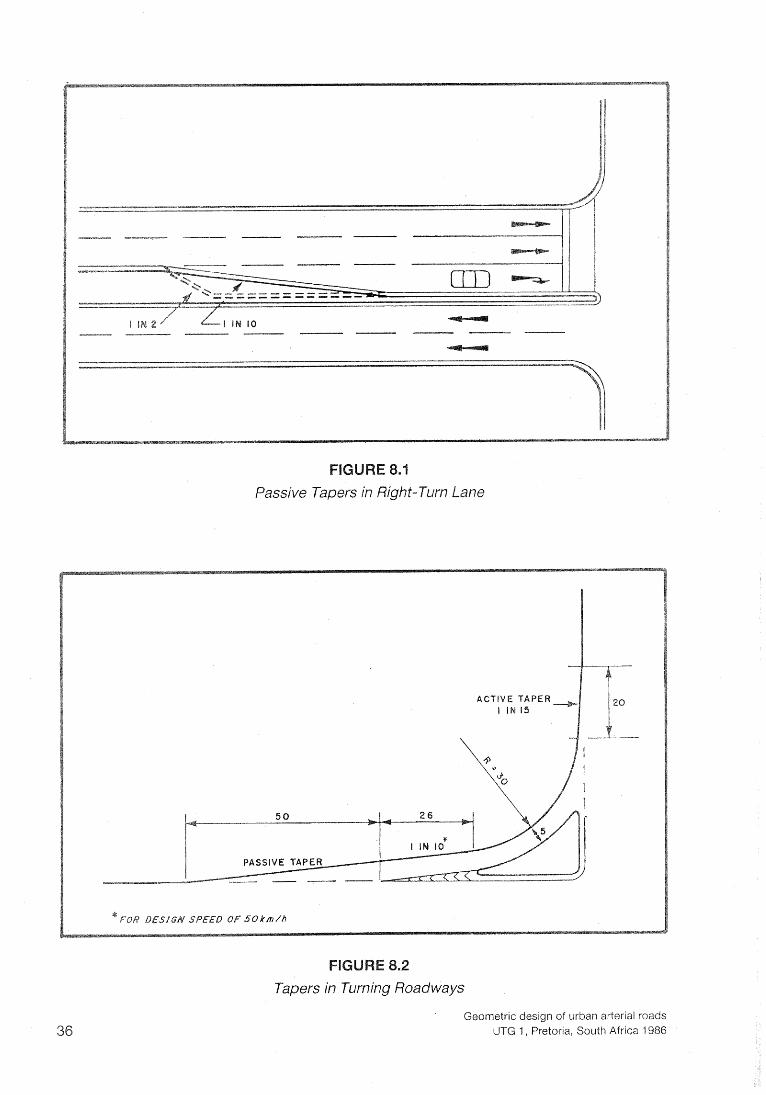
Passive Tapers in Right-Turn Lane
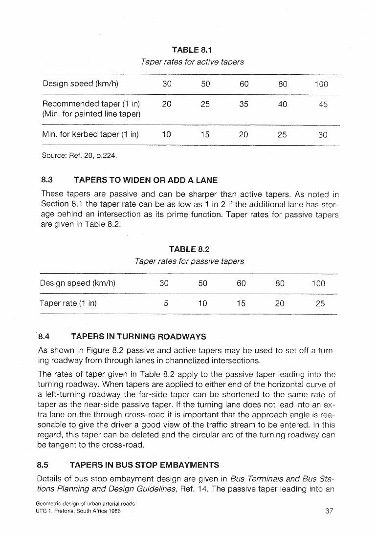
Tapers in Turning Roadways
Geometric design of urban arterial roads UTG 1, Pretoria, South Africa 1986
Taper rates for active tapers
Design speed (km/h) 30 50 60 1
Recommended taper (l in) 20 25 35 40 (Min. for painted line taper)
Min. for kerbed taper (l in) 10 15 20 25
Source: Ref. 20, p.224.
These tapers are passive and can be sharper than active tapers. Section 8.1 the taper rate can be as low as 1 in 2 ifthe additional la age behind an intersection as its prime function. Taper rates for pa are given in Table 8.2.
A Taper rates for passive tapers
Design speed (km/h) 30 50 60 I
Taper rate (l in) 5 l 0 15 20
As shown in Figure 8.2 passive and active tapers may be used to set o ing roadway from t h lanes in channelized intersections.
The rates of taper given in Tabl .2 apply to the passive taper leadin turning roadway. are applied to either end of the horizont
-side taper can be shortened to the s -side passive taper. If t e turning lane does not lead into an ex--
tra lane on the through cross-road it is important that the approach an e to give the of the traffic str am to be enter
he circular arc
Details of bus st esign are given in us Terminals and ssive taper leadin
Geometric design of urban arterial roads UTG 1, Pretoria, South Africa 1986

embayment is at a taper rate of 1 in 4. In higher speed conditions, 80 km/h or ore, this taper is increased to 1 in 6. The act €3 taper leading out of the €m-- yment is 1 in 6 in normal urban conditions an 1 in 12 for higher speed s i t ~ a -
tions.
1Nhere parallel parking is provided off the travelled way of an arterial in an ern- yment the normal practice is to provide tapers at the start and end of the ern-
ayments, both at a taper rate of 1 in 2. In such a case demarcation for parking is desirable.
topographical and existing development constraints the designer of ur- arterial roads is often confronted with tight design situations where curves to be fitted in. In high-speed rural situations a sharp curve can be given a
e of superelevation to offset the side friction forces. In urban areas with traffic conditions and limited space for embankments it is often not
tical to use high rates for superelevation.
ed design practice is to use, where possible, lar radius curves t superelevation. Where large radius curves are not poss , su~ereleva- n be introduced to offset the side friction forces of small radius curves.
le 9.1, the minimum radius values of horizontal curves for different design are derived from the formula,
= v2
= radius of curve in metres V = design speed in km/h e = superelevation rate in metres per metre f = sidefrictionfactor 127 = a constant for metric units.
Geometric design of urban arterial roads UTG 1, Pretoria, South Africa 1986
Minimum radius for horirc~ntai curv ----- --
Design Side Minimum radius for maxirnu speed friction km/h factor (9 -0,02 0
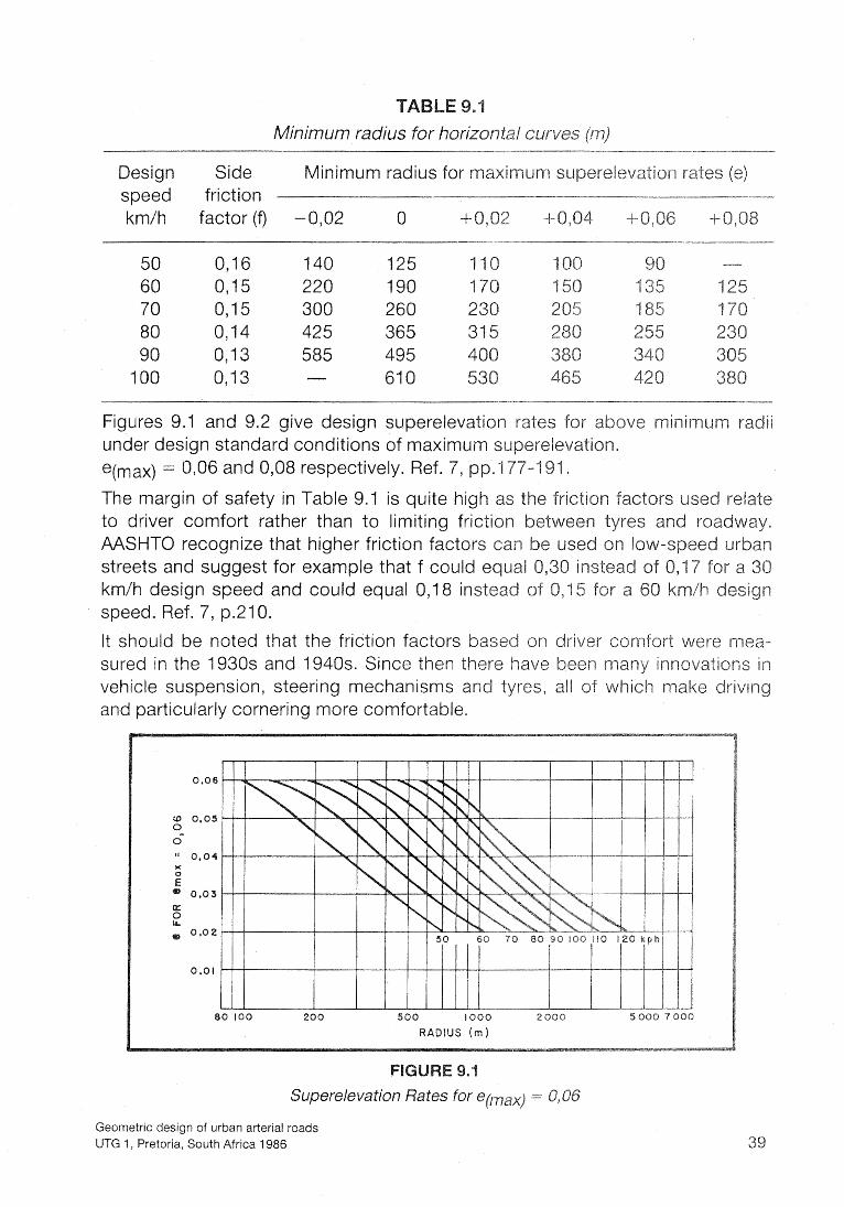
Figures 9.1 and 9.2 give design superelevation rates f under design standard conditions of maximum s e(max) = 0,06 and 0,08 respectively. Ref. 7, pp.1
The margin of safety in Table 9.1 is quite high as t to driver comfort rather than to limiting friction AASHTO recognize that higher friction factors can streets and suggest for example that f could e km/h design speed and could equal 0,18 instead speed. Ref. 7, p.210.
It should be noted that the friction factors based on driver co fort were mea- sured in the 1930s and 1940s. Since then there have been innovatisiffls in vehicle suspension, steering mechanisms and tyres, all of which make drivm and particularly cornering more comfortable.
, m w w * m
Superelevation Rates for em,,) = O,O6
Geometric design of urban arterial roads UTG 1, Pretoria, South Africa 1986
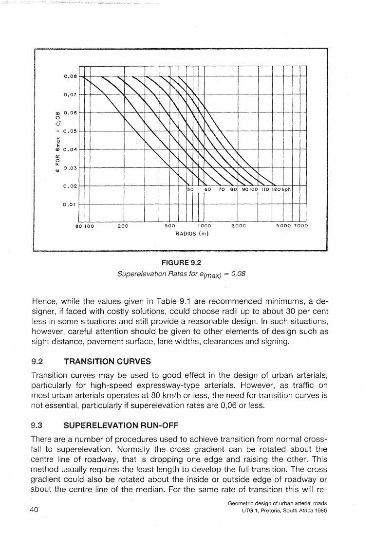
nce, while the values given in Table 9.1 are recommended minimums, a de- er, if faced with costly solutions, could choo radii up to about 30 per cent in some situations and still provide a reaso le design' In such situations' ever, careful attention should be given to o elements of design such as t distance, pavement surface, lane widths, clearances and signing.
nsition curves may be used to good effect in the d ign Of urban arterials'
rticularly for h h-speed expressway -type arterials. Owever' as traffic On st urban arteri operates at $0 b l / h or less, the i-leed for transition Curves is
ential, particularly if su rates are O D 6 Or less*
Geometric design cf urban arterial roads UTG 1, Pretoria, South Africa 1986
quire twice the length as rotation around the centre line. Attention must to potential differences in elevation across the median.
The basic principles are to achieve visually smooth transitions and proper drainage run-offs.
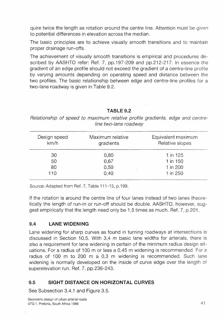
The achievement of visually smooth transitions is empirical and scribed by AASHTO refer: Ref. 7, pp.197-209 and pp.212- gradient of an edge profile should not exceed the gradient of a centre by varying amounts depending on operating speed and di two profiles. The basic relationship between edge and cen two-lane roadway is given in Ta
A Relationship of speed to maximum relative profile gradients, e
line two-lane roadway
Design speed Maximum relative km/h gradients
Source: Adapted from Ref. 7, Table 1 1 1 -1 3, p.199.
If the rotation is around the centre line of four lanes instead of two lanes t tically the length of run-in or run-off should be double. AASHT gest empirically that the length need only be 1,5 times as much.
Lane widening for sharp cu S as found in turning roadways at inter discussed in Section 10.5. th 3,4 m basic lane widths for arteria also a requirement for lane widening in certain of the minimum ra uations. For a ra ius of 100 m or less a 0,45 m widening is recomme radius of 100 to 200 m a 0,3 m widening is recommended. widening is normally developed on the inside of curve edge over t superelevation run. Ref. 7, pp.236-243.
See Subsection
Geometric design of urban arterial roads UTG 1, Pretoria, South Africa 1986

in addition to the preceding suggested standards concerning horizontal align- ent, the following general statements are presented as design supplements: f. 22, pp.12-14.
i i i)
iv)
v)
v i)
vii)
n higher type arterials,alignment should be as directional as possible, but consistent with topography and with preserving developed properties and community values. On lower types, the alignment should both enhance sce- nic views and discou high-speed traffic. The ali nment should minimize
sive cuts or fills, sharp inducing sections, or cut throughs.
Sharp horizontal curvature should not be introduced at or near the top of a pronounced crest vertical curve, nor at or near the low point of a pro- nounced sag vertical curve.
Consistent alignment is necessary. A driver should not be surprised. Sharp curved sections after long straight sections should be avoided.
Independent horizontal alignment can be employed on divided roadways to increase safety and better fit existing physical design restraints.
s a rule of thumb, the maximum number of breaks in the course of a hori- zontal line that a driver can see should not exceed two.
alignment should always be smooth and avoid kinks due to small de- flection angles, except at beginnings of turning lanes.
roken-back curves are not desirable.
cal alignment is the combinatio of parabolic vertica curves and tangent ions of a particu r slope. The selection of rates of grade and lengths of ver-
rves is base on assumptions about characteristics of the driver, the and the roadway.
rvature may impose limitations on sight distance, particularly when with horizontal curvature. The slope of ta gent sections introduces h affect vehicle S eed, driver comfort an ility to accelerate
the whole-life economy of the road in the mind, vertical alignment should ys be designed o as high a standard as is consistent with the topography.
he vertical alignment should also be designed to be aesthetically pleasing. In due recognition should be given to the inter-relationship
izontal and vertical curvature. As a curve that coin- s with a horizontal curve should, i within the hori-
zontal curve, and should ideally have approximately the same length.
Geometric design of urban arterial roads UTG 1 , Pretoria, South Africa 1986
A smooth grade line with gradual changes appropriate to the class of roa the character of the topography is preferable to an alignment with nur short lengths of grade and vertical curves. The "roller coaster" or "hidd type of profile should be avoided. A broken-back alignment is not desirable on aesthetic grounds in sags where a full view of the profile is possible. o n crests the broken back adversely affects passing opportunity.
As long as the driver's line of sight is contained within the width of the d by horizontal curvature improves the avai
profiles may have a curvature sha the minimum sugge the line of sight goes beyond the edge, the effect on sight distance of lateral obstructions such as cut faces or high vegetation must be checked.
The rate of vertical curvature, called K, is the distance required to effect er cent change of grade. Vertical curves are specified in terms of this factor,
where L = length of vertical curve in metres and A = the algebraic difference between
fr The minimum rate of curvature is determined
grades in percentage.
by sight distance as well considerations of comfort of operation and aesthetics. The sight distance most
is the stoppin sight distance measured from an eye ect height of 0,15 m, although special circumstances may cision sight distance or even passing si ht distance. In &he
case of sag curves, the si ht distance is replaced by a headli ht illumination tance of the same magnitude, assuming a headlight height of 0,6 m and a diver- gence angle of 1 degree above the longitudinal axis of the headli
Values of K, based on stopping sight distance in the case of crest curves, and headlight illumination distance in the case of sag curves, are given in Table 9.3.
successive grades is small, the inter- vening minimum vertical curve becomes very short, and, particularly where tangents are long, this ca create the impression of a kink in the Where the difference in gr e is less than 1 , per cent, the vertical cu omitted. For algebraic differences in reater than 1, lenghts are suggested in Ta .4 for purely aesthetic reasons.
Geometric design of urban arterial roads UTG 1, Pretoria, South Africa 1986

Sag
ased on a level section. Adjustt~ents required for gradient.
dapted from Ref. 10, Table 4 - 2 1
Geometric design of urban arterial roads UTG l , Pretoria, South Africa 1986
Truck speeds are, however, markedly affected by gradient. The design s therefore aim at gr dients which will not reduce the speed of heavy ve enough to cause i olerable conditions for following drivers. Overseas e ence has indicated that the frequency of truck accidents incre truck speed is reduced by more than 15 km/h, and for South a speed reduction of 20 km/h has provisionally been accept intolerable conditions. If grades on which the truck speed re 20 km/h cannot be achieved economically, it may be ne auxiliary lanes for th slower-moving vehicle flat grades truck speeds are about 17 km/h lo that a speed reduction of 20 km/h actually represents a total between trucks and passenger cars of about 37 krn/h.
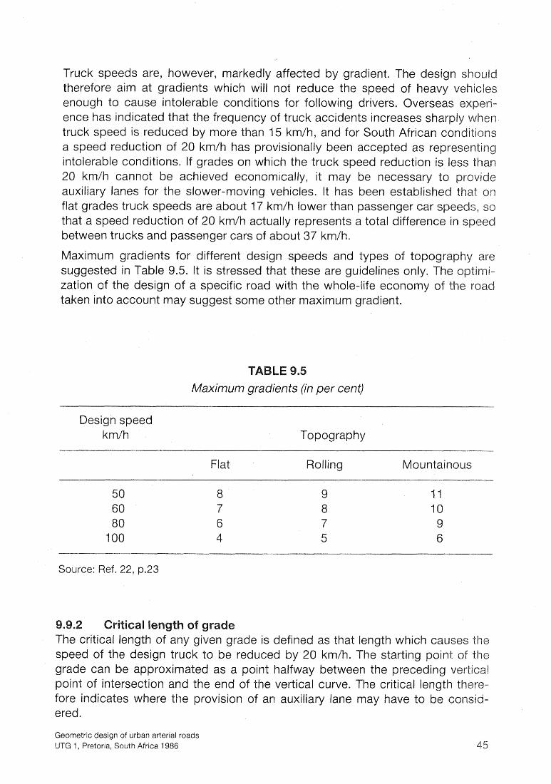
aximum gradients for different design speeds and types of topogra suggested in Ta le 9.5. It is stressed that these are guidelines only. The zation of the de gn of a specific road with the whole-life economy of t taken into account may suggest some other maximum gradient.
Maximum gradients (in per cent)
Design speed kmlh Topography
Flat Rolling Mountainous
Source: Ref. 22, p.23
efined as that length which causes the ck to be reduced by 20 km/h. The starting point o
'nt halfway between the preceding ve he vertical curve. The critical le
fore indicates where the provision of an auxiliary lane may have ered.
Geometric design of urban arterial roads UTG 1, Pretoria, South Africa 1986
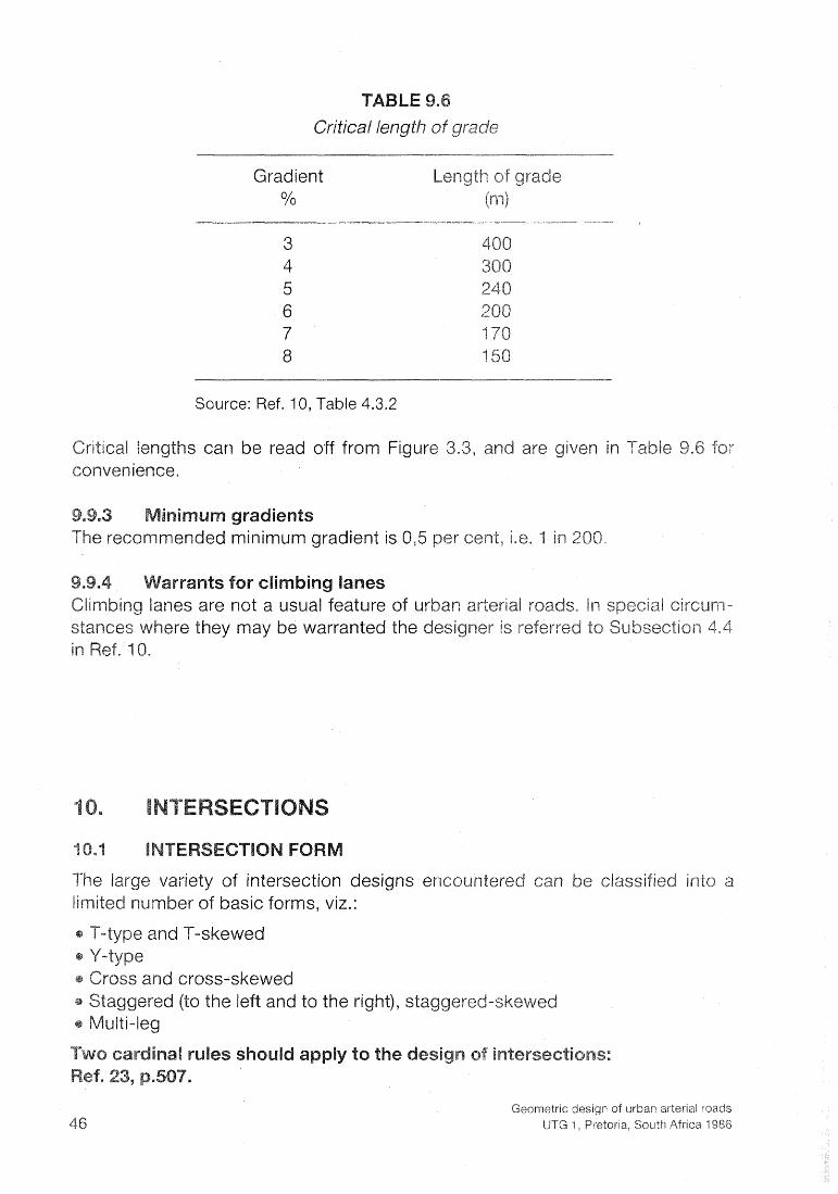
Gradient Length of gra %
W. --m
3 4 5 6 206 7 19 8 I 50
Source: Ref. 10, Table 4.3.2
s can be read off from Figure 3.3, a
radient is 0,5 per e
ariety of intersection designs e countered ca er of basic forms, viz.:
and to the right), sta
Geometric design of urban arterial roads UTG 1 , Pretoria, South Africa 1986

(1) No intersection should be planned for more than four two-way intersecti legs.
(2) The angle of crossing manoeuvres should be approximately a ri movements intended to operate at high relative speed.
rt ri E?
Figure 10.1 shows the intersection forms recom sheet 1. A multi-leg intersection should not be pro
ment schemes, e isting multi-leg inters four-leg intersections through channelizing procedures.
Staggered intersections are acceptable when the distance between the legs is adequate for weaving and storage of right-turning vehicles. When thi distance is adequate, design becomes that for two intersections, each of legs. The preferred direction for the offset should be such that traffic tra from one of the minor roads onto the other via the arterial road shoul do so without making a right turn from the arterial road.
2 APPROACHES TO BE CONTROLLED) T-TYPE WITH INTERSECTION WIDENING
UAlNTAlN AT LEAST STOPPtlO SIGHT DISTANCE
T -TYPE ON OUTSIDE OF CURVE Source : Ref. 2 4 , F i g . 2 1 , Sheet I
REVERSE S K E W
Geometric design of urban arterial roads UTG 1, Pretoria, South Africa 1986
lnfersecfion Forms

Uniform spacing promotes progressive flow of traffic through signalized i sections. With spacings between 500 m and 600 m optimum progression c achieved. Every effort should be made for such uniform spacings altho practice, the intersection location is often governed by topography and pr velopment. Ref. 25;p.I 05.
No hard and fast rules can be laid down for the spacing of intersections. Tra offs have to be considered. Infrequent spacing promotes faster and smoo traffic flow with fewer conflict situations. However, traffic volum
W intersections available. In a tion less traffic service is given to the surrounding development.
The minimum degree of control woul be yield control. In other circumstances the minor road may have stop control, while the arterial road has priority. Inter- section design should make provision for the eventual control of all four-le tersections by signals.
The sight distance required in the design of intersections depends on the type o control at the intersection.
ersection, the river of a stationary vehicle must be a major road to be able to cross before an approaching v section, even if this vehicle comes into view just as the
stopped vehicle starts to cross.
The distance the crossin vehicle must travet is the sum of the distance fr stop line to t edge of the through ro y, the width of the roa crossed and t This manoeuvre must
icle to reach the inte roaching vehicle is y, the time availab also include all
stablish that it is safe to cro
oint on the centr line of the crossing road an h road to a point on the centre line of the
ht is 1,3 m. The eye height is assenger car an 1,8 m for all other ion to the vievi in
e and the centre
Geometric design of urban arterial roads UTG 1, Pretoria, South Africa 1986
0 20
Source : R e f . 10,
1
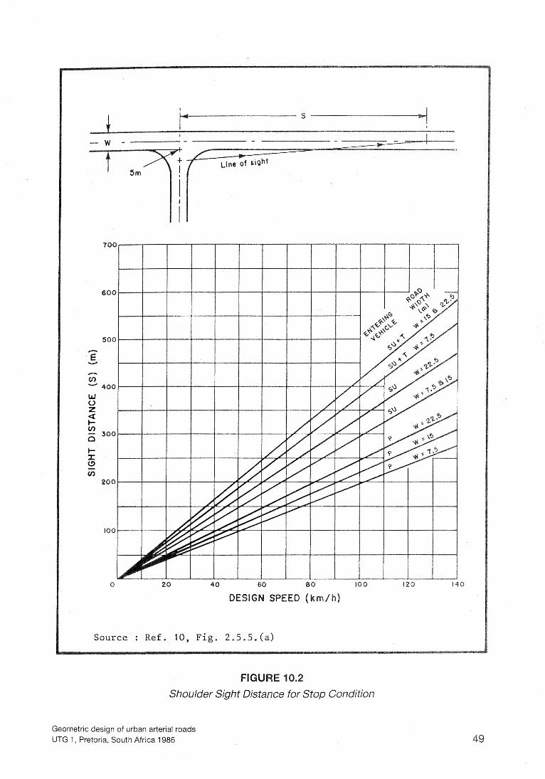
F i g , 2.5.5. (a)
Shoulder Sight Distance for Stop Condition
Geometric design of urban arterial roads UTG 1, Pretoria, South Africa 1986

Shoulder sight distances, recommende in accordance with the principles ou lined above, are given in Figure 10.2. Before a lower value is adopted in specific case, the implications of departing from the recommended valu should be studied.
where an intersection approach is controlled by a yield d that a driver on that approach will reduce his speed suf- either to stop or to accelerate and pass through t
section. Ref. 26, p.4.31
The required sight line for this condition is established by the stopping sight dis- tance for the reduced speed along the controlled approach, and by the distance that a vehicle would travel along the uncontrolled approach during the time that it would take for the vehicle on the yield approach to enter and pass through the intersection. He suggests an approach speed on the yield-controlled approach of 25 km/h for urban conditions. The distance required for the vehicle to decel- erate to standstill would be 24 m (see Figure 10.3). If the vehicle on the crossin road does not stop, but turns to travel in the same direction as a vehicle proaching at the design speed of the throug road, the driver on the throu road would be forced to slow down to match speeds at a safe following dis- tance, and the distance, S, allows for this speed adjustment.
Turning manoeuvres at urban intersection are made at much lower speed than the basic operating speed of the arterial road.
t turns involve direct crossin osing vehicle paths and are usu e at minimum spee S of 15 km/h or less. Ref. 26, p.4.43.
Left turns are also made at low speed but speeds would generally be higher than the right-turn spe S. Drivers do respon he restricted speed require in turning through an ersection. It is reco at speeds on turnin roadways be consider S being in the range
tolerable for the lo speeds used in intersectio below records the uggested side friction factor se friction factors vary from 0,27 for 3
to 0,45 for 10 km/h. Ref. 7, p.220.
Geometric design cf urban arterial roads UTG 1, Pretoria, South Africa 1986

Source : Adapted from R e f . 10, F i g . 2 . 5 . 5 . ( b )
Shoulder Sight Distance for Yield Condition
Geometric design of urban arterial roads UTG 1, Pretoria, South Africa 1986

Speed-curvature relationships for intersections
Speed V (km/h) 10 15 25 35 Side friction factor f 0,45 0,38 0,32 Assumed minimum superelevation e 0,OO 0,OO 0, Calculated safe minimum radius R (m) 2 5 I Recommended design radius (m) 12 12 15 p---. -
Source: Adapted from Ref. 7 , Table 111-16, p.220.
Problems associated with the vertical grading of intersections frequently permit superelevation to be applied to turning movements. The lower spe 10 km/h to 25 km/h can be maintained with no superelevation and smal When speeds above 25 km/h are desired, a minimum of 0,02 of superel should be applied.
Table 10.1 shows the speed-curvature relationships for turning movemen- intersections. For the lower speeds the radius is controlled more by the turni characteristics of the vehicle than the speed-curvature relationship.
Table 10.2 shows the recommended widths of turning roadways associate intersection channelization. The widths are set out in terms of three di erating cases:
Case I for single-lane one-way operation without any provision for passin
Case II is also for single-lane one-way operation, but makes provision for pass- ing a stalled vehicle.
Case Ill makes provision for two-lane operation, whether it be one-way or two- way.
Each of these operating cases requires different lane widths, depending on the e of vehicle governing the design.
Ghannelization can be defined as the use of islands at intersections to direct traffic along definite paths to simplify operations. f. 23, p.503. The of channelization are:
rate manoeuvre areas and present drivers with one decision at a ti ol the manoeuvre angle to obtain small angles for merging and th
verging at low relative speeds and crossing at approximate right angles at
Geometric design of urban arterial roads UTG 1 , Pretoria, South Africa 1986

Design widths for separate turning roadways of various radii
Pavement width (m) for:
R Case I Case ll Case &l Radius on l -lane, l -way 2-lane, inner edge
of carriageway passing a stalled passing a stalk
(m) vehicle vehicle
Design traffic co
AI E32 c3 AI €32
Width modification regarding edge of pavemen
Mountable curb one
arrier curb: Add 0, Add 0,
one
None
I~ ra f f i c condition A - Predominantly passenger vehicles, but some consideration for single-unit (SU) trucks.
2Traffic condition B - Sufficient SU vehicles to govern design, but some consideration for semi-trailer vehicles.
3~raff ic condition C - Sufficient bus and combination-types of vehicles to govern de- sign.
Source: Ref. 7, p.232.
Geometric design of urban arterial roads UTG 1, Pretoria, South Africa 1986

o control speed by bending or funneling To provide a refuge between traffic flows for pedestrians
o provide protection and storage of turning and crossing vehicles o eliminate excessive intersectional areas which permit drivers to perform
improper manoeuvres or to travel along unpredictable paths c To prevent illegal manoeuvres
o provide space and protection for traffic control devices
ffic lanes so formed should be delineated by traffic islands preferably by semi-mountable or barrier kerbs. Islands may be classed into three
irectional islands which direct the traffic along the correct channel or prevent illegal manoeuvres
ivisional islands which separate opposing traffic flows efuge islands to protect pedestrians crossing the roadway or to accommo-
date traffic control devices
e avoided as they have low visibility and are unable to afely accommodate traffic signs or other control devices. The minimum width
m. The minimum area of island should be 5 m? Islands ge should preferably be 2 m wide with a minimum of 1,2
kerbs. Where wheelchair access is to be considered a inimum width of 1 , s m is needed together with ramped kerbs.
by poorly designed islands are related to in- uate approach-end treatment. The points at the intersections of the side of
should be rounded for visibility.
S are usually introduced suddenly and should be offset from the edge sic lanes. A mountable kerb need not be offset from the edge of a turning
y except that ould preferably be offset an ad- 0,5 to 1,0 m t ty. Barrier kerbs should be offset edges of through and turning roadways.
d of an island should be CO uous to approaching drivers finitely clear of vehicle pat ysically and visually so that
rivers will not veer from the island. The approach nose should be offset an ount greater t n that of the side of the island itself. Where feasible the total
ose offset shou be 1,O m to 2,O m from the normal edge of the through road- y and O , 5 m to 1 , O m from the pavement edge of the turning roadway. Ref. 7,
nd Ref. 3 , p.DI6.
ure 10.4 shows how offset to triangular islands should be handled.
Geometric design of urban arterial roads UTG 1, Pretoria, South Africa 1986
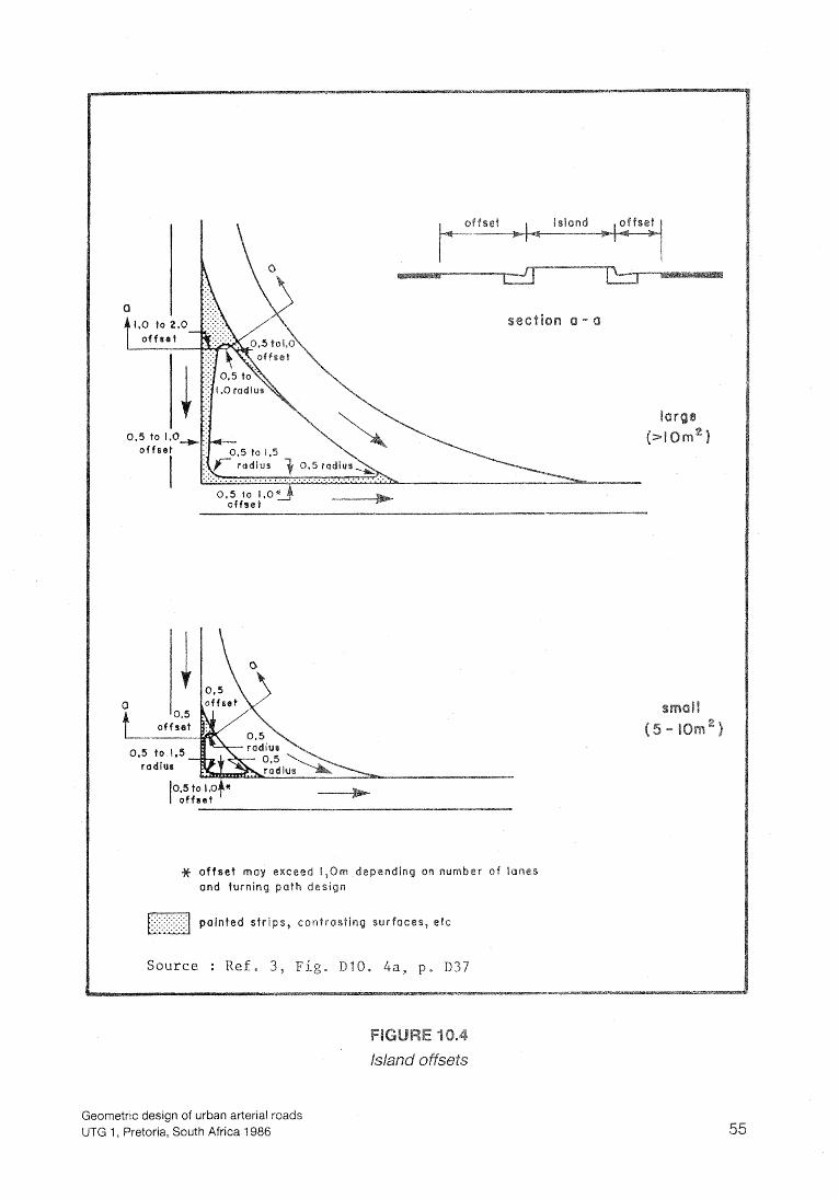
Geometric design of urban arterial roads UTG 1 , Pretoria, South Africa 1986
# o f f s e t may exceed 1,Om dependinq on n u m b e r o f lanes a n d turning path design
painted strips, contras t in
S o u r c e : Ref. 3 , F i g . D 1 0 . 4a, p . 037
ht-turn lanes are required to provi ace for right-turnin le they wait for aps in the opposi ffic to make the rig ile they wait for the appropriate signal indication to do so.
The minimum length of right-turn lane should provide stora e for at least two ith more than l 0 per cent rovision should e made for at
one car and one truck.
gth of storage lane de s on the volume of right-turning t
rage number of vehicles tu ight per signal cycle.
re 10.5 shows the length of left and right-turn lanes that should be provided naked intersections. Ref. 22, Figs. 9.2 and 9.3, p.35.
ure 10.6 shows the length of right-turn storage lanes to be provided on four- e at-grade unsignaiized intersections. Ref. 22,
e r to Subsection 5.4.
lied in determini
ching onto a lane that might be
and fast rule can or the treatment at the intersection. h simple curve pl rve radii associate
us treatments of left-turn desi n commonly 2 4 and 26, sheets 1-5.
Geometric design of urban arterial roads UTG 1, Pretoria, South Africa 1986
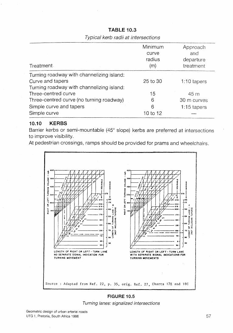
T Typical kerb radii at intersections
Treatment
Minimum curve radius
(m)
ay with channeiizing island: 25 to 30
with channelizing island: 15 45 rn
Three-centred curve (no turning roadway) 6 Simple curve and tapers 6 Simple curve 10 to l 2 -
semi-mountable (45" slope) kerbs are preferre
At pedestrian crossings, ramps should be provided for prams and
TURNING MOVE
LENGTH OF RlOHT OR LEFT - TURN
;ourcc : Adapted f rom Ref. 22, p , 3 5 , orig. Ref . 27, Charts 17E and f B C
.5
Turning lanes: signalized intersections
Geometric design of urban arterial roads UTG 1, Pretoria, South Africa 1986
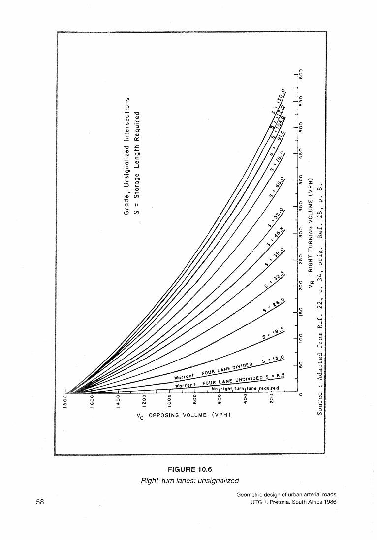
Righ t-turn lanes: unsignalized
Geometric design of urban arterial roads UTG 1, Pretoria, South Africa 1986

Typical left- turn designs
Geometric design of urban arterial roads UTG 1, Pretoria, South Africa 1986

Geometric design of urban arier~al roads U7-G 1, Pretoria, South Africa 1986
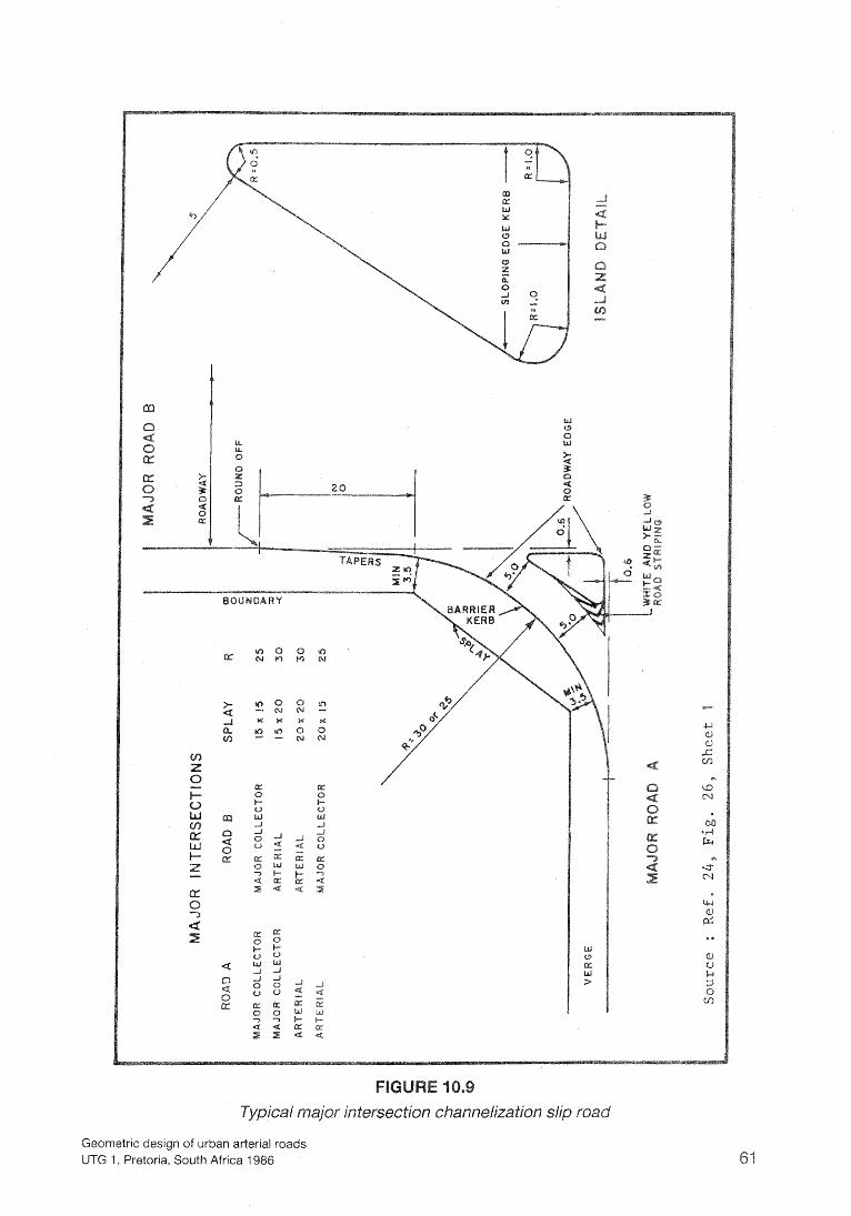
Geometric design of urban arterial roads UTG 1, Pretoria, South Africa 1986
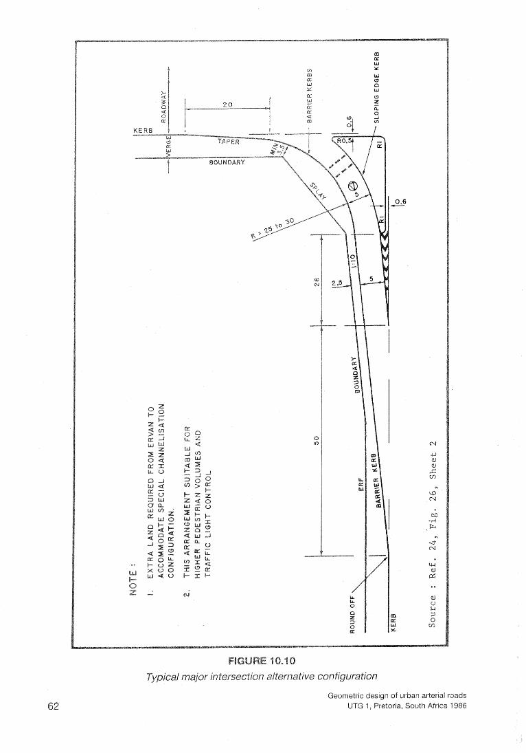
Typical major intersection alternative configuration
Geometric design of urban arterial roads UTG 1, Pretoria, South Africa 1986

Geometric design of urban arterial roads UTG 1 , Pretoria, South Africa 1986
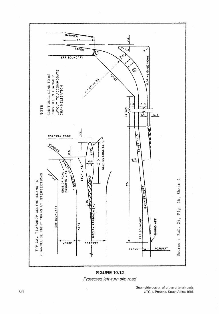
Geometric design of ur UTG 1, Pretoria, South Africa 1986
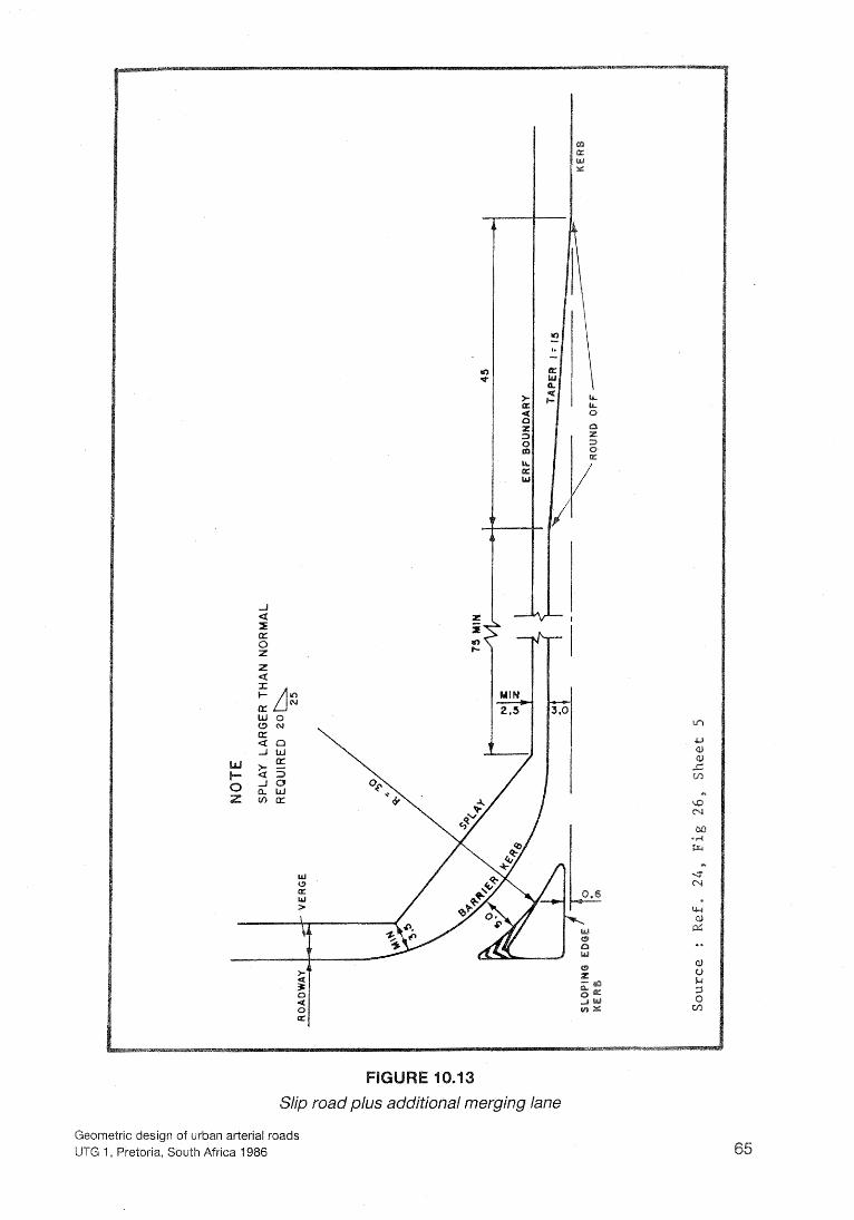
Geometric design of urban arterial roads UTG I , Pretoria, South Africa 1986
HlGHWAY RESEARCH BOARD. Highway Capacity Manual. Special Report 87. Wash-
PORTATION RESEARCH BOARD. Highway Capacity Manual. Special Report shington, DC, 1985.
D TRANSPORT ASSOClATlO OF CANADA. Geometric Design Standards for Canadian Roads and Streets. Ottawa, 1976.
. Traffic Circulation Planning for Communities.
AY RESEARCH BOARD. Protection of Highway Utility. National Cooperative y Research Program Report 121. Wa hington, DC, 1970.
DEPARTMENT OF COMMUNIW DEVELOPMENT. Guidelines for the Provision of En- gineering Services for Residential Townships. Pretoria, Government Printer, 1983.
ERICAN ASSOCIATION OF STATE HIGHWAY AND TRANSPORTATION OFFI- LS. A Policy on Geometric Design of Highways and Streets. Washington, DC,
MITH, R W, JAC SON, R I. Towards Geometric Design Standards for Major Roads in Metropolitan Areas. Annual Transportati n Convention ATC 1985. Council for Sci- ntific and lndustrial Research. Pretoria, Au
FIELD, H$ ALEXANDER, G J. Human Factors in Highway Design and Opera- ions. Journal of Transportation Engineering, Vol. 11 0, No 2. New York, American So-
ciety of Civil Engineers, March 1 984.
EARCH. Geometric De
ELCAN IN ASSOCIATION WITH VALCOUSTICS. Geometrical Design Standards for nadian Roads and Streets. RTAC Manual Update 19 4/85, Preparation of Fir
SPORT. Parking Standards. Pretoria, Urban Transport
nual. Updated Re rint. Cape Town,
PARTMENT OF TRANSPORT. us Terminal and Bus tations Planning and Des~ . Draft Report for Use and Comment. Pretoria, July 1983.
ccelerafion Curve of Commercial Vehicles for the De g Transport Conference. Johannesburg, South
M, BESTER, C J, SIK, J R. Truck Climbin bility in the Highveld. NlTRR /€U. Pretoria, Council for Scienti nd Industrial Research, Oc-
, H B. Eye He ht of Drivers of Cars and Vans. NlTRR Technical Report toria, Council f Scientific and Industrial Research, 1 976.
Geometric design of urban arterial roads UTG 1, Pretoria, South Africa 1986

18. BRAFMAN BAHAR, G. A Need for Revised Geometric Standards Based on Stopping Sight Distance and Driver Eye Height. NlTRR Technical Report RF/3/83. Pretoria, Council for Scientific and Industrial Research, 1983.
19. VISSER, A. Design and Maintenance Criteria for Improved Skid Resistance of Roads. NlTRR Technical Report RC6/75. Pretoria, Council for Scientific and lndu-stria1 Re-
20. COUNCIL FOR SCIENTIFIC A D INDUSTRIAL RESEARCH. The South African Road and Traffic Signs nual. Second Edition. Pretoria, 1 982.
83. Act No 6. Cape Town, Governm Gazette No. 8573, 2 March, 1983.
22. ITE. Guidelines for Urban Major Street Design. A Recommended Practice of the lnsti- of Transportation Engineers. Washington, DC, 1984.
23. MATSON, T M. SMITH, W S and HURD, F W. Traffic Engineering. New York, McGraw-Hill, 1955.
24. SOUTH AFRICAN INSTITUTE OF CIVIL ENGINEERS. Guidelines on the Planning and Design of Township Roads and Storm water Drainage. 2nd Edition. Johannesbur gust 1981.
25. HIGHWAY RESEARCH BOARD. Guidelines for Medial and Marginal Access Cont on Major Roadways. National Cooperative Highway Research Program R Washington, DC, 1970.
26. JACK E LEECH AND ASSOCIATES. Planning and Design Guide At-grade lnte tions. Evanston, Illinois, Distributed by Transportation Design Techniques, Inc., tern ber 1 981.
27. LEISCH, J E. Capacity Anaiysis Techniques for De n of Signalized Inferse o. 10, Washin ton, DC, Depa nt of Transportatio
28. HARMELIN M D. Volume Warrants for Left-Turn rade lnfersections. M ighwa
Research Board, National Research Council, 1967.
EERS. Guidelines for Driveway Desi
30. TRANSPORTATION RESEARCH BOARD. Locatio lection and Maintenance sl" fi-affic Barriers. Washin arch Council, 1971.
OF STATE HIGHWAY A CIALS. Guide for Selecting, Locating and Designing Tra 1977'
Geometric design of urban arterial roads UTG 1, Pretoria, South Africa 1986


![Index [ ] · PDF fileIndex UTG UTG UTG UTG 3 • Circular connectors Page ... Full plastic circular connector UTP - Full plastic Bantam 15 Shielded connectors... how to](https://static.fdocuments.in/doc/165x107/5a9df0247f8b9adb388c10a2/index-utg-utg-utg-utg-3-circular-connectors-page-full-plastic-circular.jpg)