20RD/20RI Installation Manual - OSO · PDF fileCold water supply to be 22mm nominal size. 2....
16
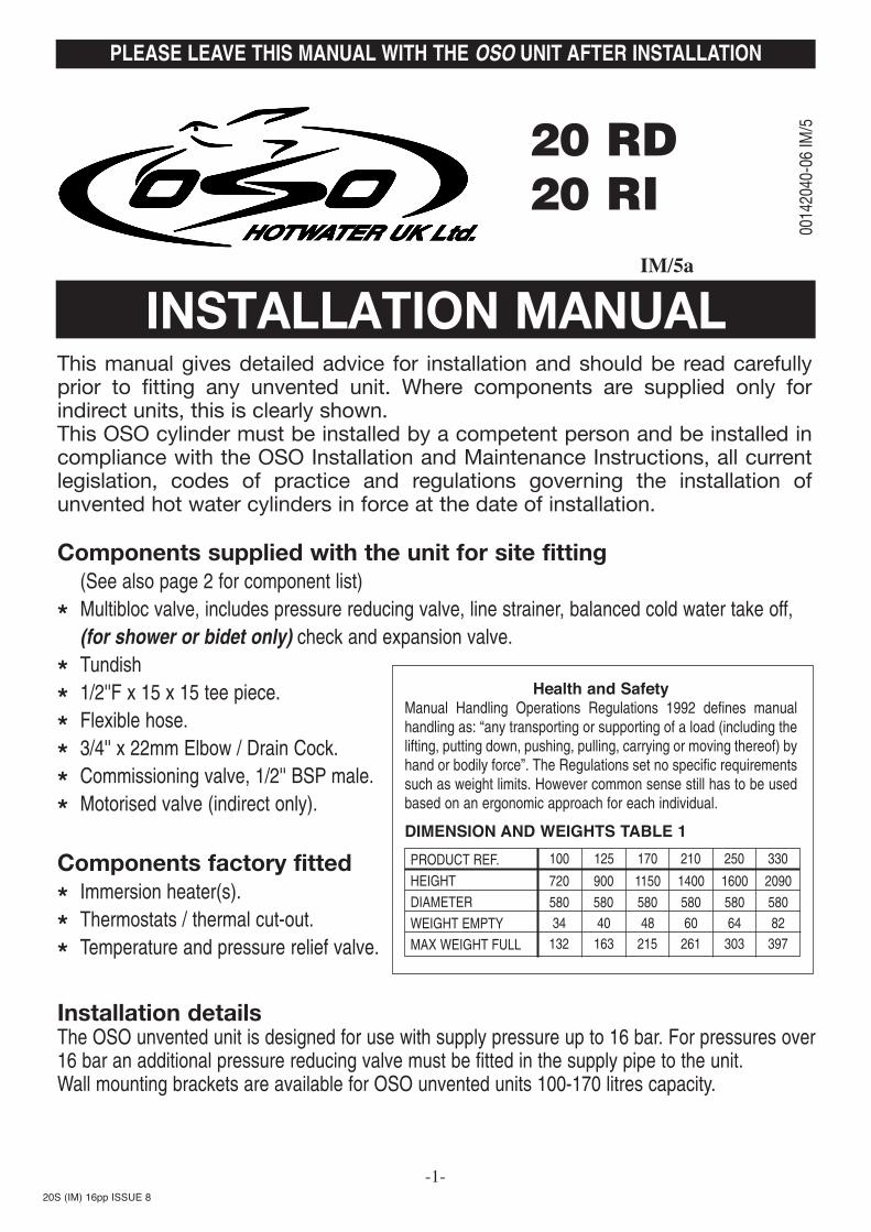
20 RD 20 RI IM/5a Installation details The OSO unvented unit is designed for use with supply pressure up to 16 bar. For pressures over 16 bar an additional pressure reducing valve must be fitted in the supply pipe to the unit. Wall mounting brackets are available for OSO unvented units 100-170 litres capacity. Components supplied with the unit for site fitting (See also page 2 for component list) * Multibloc valve, includes pressure reducing valve, line strainer, balanced cold water take off, (for shower or bidet only) check and expansion valve. * Tundish * 1/2''F x 15 x 15 tee piece. * Flexible hose. * 3/4'' x 22mm Elbow / Drain Cock. * Commissioning valve, 1/2'' BSP male. * Motorised valve (indirect only). Components factory fitted * Immersion heater(s). * Thermostats / thermal cut-out. * Temperature and pressure relief valve. This manual gives detailed advice for installation and should be read carefully prior to fitting any unvented unit. Where components are supplied only for indirect units, this is clearly shown. This OSO cylinder must be installed by a competent person and be installed in compliance with the OSO Installation and Maintenance Instructions, all current legislation, codes of practice and regulations governing the installation of unvented hot water cylinders in force at the date of installation. -1- PLEASE LEAVE THIS MANUAL WITH THE OSO UNIT AFTER INSTALLATION INSTALLATION MANUAL PRODUCT REF. HEIGHT DIAMETER WEIGHT EMPTY MAX WEIGHT FULL 100 720 580 34 132 900 580 40 163 1150 580 48 215 125 170 1400 580 60 261 210 1600 580 64 303 250 2090 580 82 397 330 DIMENSION AND WEIGHTS TABLE 1 00142040-06 IM/5 Health and Safety Manual Handling Operations Regulations 1992 defines manual handling as: “any transporting or supporting of a load (including the lifting, putting down, pushing, pulling, carrying or moving thereof) by hand or bodily force”. The Regulations set no specific requirements such as weight limits. However common sense still has to be used based on an ergonomic approach for each individual. 20S (IM) 16pp ISSUE 8
Transcript of 20RD/20RI Installation Manual - OSO · PDF fileCold water supply to be 22mm nominal size. 2....
20 RD20 RI
IM/5a
Installation detailsThe OSO unvented unit is designed for use with supply pressure up to 16 bar. For pressures over16 bar an additional pressure reducing valve must be fitted in the supply pipe to the unit.Wall mounting brackets are available for OSO unvented units 100-170 litres capacity.
Components supplied with the unit for site fitting(See also page 2 for component list)
* Multibloc valve, includes pressure reducing valve, line strainer, balanced cold water take off, (for shower or bidet only) check and expansion valve.
* Tundish
* 1/2''F x 15 x 15 tee piece.
* Flexible hose.
* 3/4'' x 22mm Elbow / Drain Cock.
* Commissioning valve, 1/2'' BSP male.
* Motorised valve (indirect only).
Components factory fitted
* Immersion heater(s).
* Thermostats / thermal cut-out.
* Temperature and pressure relief valve.
This manual gives detailed advice for installation and should be read carefullyprior to fitting any unvented unit. Where components are supplied only forindirect units, this is clearly shown.This OSO cylinder must be installed by a competent person and be installed incompliance with the OSO Installation and Maintenance Instructions, all currentlegislation, codes of practice and regulations governing the installation ofunvented hot water cylinders in force at the date of installation.
-1-
PLEASE LEAVE THIS MANUAL WITH THE OSO UNIT AFTER INSTALLATION
INSTALLATION MANUAL
PRODUCT REF.
HEIGHT
DIAMETER
WEIGHT EMPTY
MAX WEIGHT FULL
100
720
58034
132
900
58040163
1150
58048
215
125 170
1400
58060
261
210
1600
58064
303
250
2090
58082
397
330
DIMENSION AND WEIGHTS TABLE 1
0014
2040
-06
IM/5
Health and SafetyManual Handling Operations Regulations 1992 defines manualhandling as: “any transporting or supporting of a load (including thelifting, putting down, pushing, pulling, carrying or moving thereof) byhand or bodily force”. The Regulations set no specific requirementssuch as weight limits. However common sense still has to be usedbased on an ergonomic approach for each individual.
20S (IM) 16pp ISSUE 8

-2-
General Layout Fig:1
1
2
3
4
5
6
7
7A
8
9
Return 3/4'' BSPF*
Flow 3/4'' BSPF*
Pressure Reducing Valveincludes item 4
Check and Expansion Valve
Temperature and PressureRelief ValveTundish
Immersion HeaterThermostat Immersion Heater Thermostat Cylinder
Cold Feed Tube(Not Supplied See Table 2)
Hot Water Outlet 22mm
510511
510505
550803
219002
712598002080030
10
11
12
13
14
15
16
17
18
*
Flexible HoseSecondary Return 1/2'' BSPFFit 1/2''Fx1/2''Mx15mm Tee piece (Not supplied)
Commissioning Valve / Fitting1/2'' MI Drain Cock
Elbow / Drain Cock
Cable Entry
Electrical Box
Tee Piece
Discharge Pipe (Not supplied)
Motorised Valve * (Not Factory Fitted)
Indirect Only
202108
250440
250445
250006
92000
KEY Part No KEY Part No

1. To obtain the best performance from your OSO unvented system it is advisable to feed the unitwith an uninterrupted supply.
2. Locate the water heater in a suitable position to facilitate the installation of the cold water supply,discharge fittings and pipework. Also take into account access to the immersion heaters and thecommissioning valve.
3. Fit the combined male elbow / drain cock to cold supply point (13), so that the compressionfitting is vertical.
4. Fit the commissioning valve (12) to the commissioning fitting.5. Fit the female outlet of the tee piece to the temperature and pressure relief valve (5) with the
horizontal connection facing right at approx. 45°.6. Fit the tundish (6) to the tee piece using a short length of 15mm copper tube.7. Fit the length of copper tube 22mm specified in Table 2 to the cold feed elbow (see 3 above).8. Fit the pressure reducing valve(3) to the top of the copper tube (see 7 above), so that the black
knob is facing right.9. Connect the flexible hose to the 1/2'' outlet of the expansion valve (4) and the horizontal outlet
of the tee piece (see 5 above). Discard compression nut & ring.10. If a balanced mains pressure cold water supply is required to a shower or bidet (over rim type
only, ascending spray type requires type AA,AB or AD air gap), remove the blanking capfrom the pressure reducing valve (3) and connect to the shower or bidet cold supply. (Majorshower manufacturers advise fitting a mini expansion vessel in the balanced cold supplypipework to accommodate thermal expansion and prevent tightening of shower controls)Using the balanced cold connection to feed outlets that do not require a balanced coldsupply can reduce the flow available to the unvented cylinder.
11. Before connecting the cold supply, flush the cold supply pipework of all flux and debris.12. Connect the cold supply to the pressure reduction valve (Multibloc) (3).
Hot water supply13. Connect the hot water supply pipe to the outlet (9). Ensure connection is water tight.
Secondary return14. A secondary return facility is provided on all units. Fit a 1/2''F x 1/2''M x 15mm tee piece between
the commissioning valve (12) and the commissioning fitting. See also figure 5 on page16.
Discharge pipe15. Connect the discharge pipe from the tundish (6). This must have a continuous fall and be fitted
in accordance with The Building Regulations (see pages 5 and 12).
Primary flow & return and motorised valve (Indirect only)16. The boiler primary flow and return connections should be made to the unit and include a by-pass
with automatic by-pass valve. The motorised valve must be fitted into the primary heating circuit. 17. For electrical connection of the motorised valve and immersion heater, please read Electrical
Installation Instructions. (Pages 7 - 11)
COLD WATER SUPPLY
-3-
Filling up1. Close all hot water taps.2. Open the commissioning valve (12).3. Open the cold water supply valve.4. When water flows from the commissioning valve (12), close the valve and continue to fill.5. Allow system to stabilise for five minutes.6. Open each hot water tap in turn to expel air from the system pipe work.7. Check for leaks.8. Manually operate Temperature and Pressure Relief Valve (5) to ensure free water flow through
discharge pipe. (Turn knob to left.)
DrainingSwitch the electrical power off (important to avoid damage to element). Isolate boiler from OSO unit.Turn off the cold water supply valve. Open hot water tap. Open drain (13). The unit will drain.
Safety Cut-out1. The safety cut-out operates if:
a. Wiring is incorrect.b. The immersion heater thermostat or cylinder thermostat fails.c. Thermostat is set too high.
2. Remember before resetting the safety cut-out or altering the thermostat setting, isolate electricalsupply to the unit prior to removal of the electrical box lid.
3. Reduce thermostat setting and press the reset button. After adjustments are completed, ensurethe lid to the electrical box is replaced correctly and the retaining screw is fitted.
4. If still out of operation, contact installer.
Cold or tepid water discharge from tundish1. Turn off the electrical supply to the immersion heaters.2. Turn off cold water supply valve.3. Open a hot tap.4. Drain water from commissioning valve (12) until water flow stops.5. Turn the knob on the Temperature and Pressure Relief Valve (5) to the left and hold in this
position until water flow stops from the commissioning valve.6. Close commissioning valve.7. Close all hot taps.8. Open cold water supply valve.9. Turn on electrical supply to the immersion heaters.
COMMISSIONING
SAFETY AND MAINTENANCE
-4-
Hot water discharge from tundishThis indicates a malfunction of a thermal cut-out, operating thermostat or the combined temperatureand pressure relief valve. Turn off the electrical supply to the immersion heater and also isolate anindirect unit from the boiler. Contact the installer or competent engineer.
Cold water inlet control (Multibloc) See Page 2 Items 3 - 4This combination consists of a pressure reducing valve with integral strainer, check valve andexpansion valve with stainless steel seat. The pressure settings are set and locked in the factory andare shown on the top of each valve. For optimum performance the following installation instructionsshould be complied with.
Installation1. Cold water supply to be 22mm nominal size.2. Flush supply pipework before connection to remove all flux and debris prior to fitting the inlet
controls. Failure to do this may result in irreparable damage to the controls and will invalidatethe warranty.
3. The “MULTIBLOC” can be fitted in any orientation to suit the installations as long as it is fittedin the correct flow direction. Check the flow arrows on the side of the body.
4. The expansion valve should be either horizontal or upright - if fitted inverted, debris may bedeposited on the seat and cause fouling of the seat when the valve operates. Check directionof flow arrows.
5. The black plastic plugs in the body are pressure gauge connections to enable pressuremonitoring to be carried out, should the system develop a fault. It is recommended that thesebe accessible (the pressure reducing valve has two - only one need be accessible).
6. Expansion relief drain pipework must be connected to a safe visible discharge point via atundish and the pipework must have a continuous fall.
7. The pressure reducing valve has two outlets, the second one is for a balanced cold watersupply, to a shower or a bidet (over rim type only, ascending spray type requires type AA,AB or AD air gap) (Major shower manufacturers advise fitting a mini expansion vessel inthe balanced cold supply pipework to accommodate thermal expansion and preventtightening of shower controls). Using the balanced cold connection to feed outlets thatdo not require a balanced cold supply can reduce the flow available to the unventedcylinder. The balanced cold supply is blanked off.
8. If an expansion vessel is to be fitted it must be connected to the cold feed pipe between thepressure reduction valve, (Multibloc) (3) and the cylinder.NOTE: If the unit has been commissioned and is to be unused for more than 8 weeks it isadvisable to turn off the cold supply and draw off approximately 5 litres of water through a hottap. NB The cold supply must be opened prior to use.The Benchmark Log Book enclosed with the cylinder must be completed aftercommissioning the system and handed to the customer for future reference.
INSTALLATION AND SERVICING INSTRUCTIONS
-5-

TundishInstall the tundish in a vertical position within a maximum of 500mm from the Temperature andPressure Relief Valve drain connection. Ensure the expansion relief pipework discharges through thetundish. Tundish pipework must be 22mm with a minimum vertical length of 300mm below the tundish.Maximum permitted length of 22mm pipework is 9 m. Each bend or elbow is equivalent to 0.8m ofpipework.All pipework must have continuous fall and discharge in a safe, visible position. If any doubt, refer toBuilding Regulation G3.
MAINTENANCE
-6-
Annually a competent person should:-· Inspect and clean the line strainer· Re-commission the unit air-gap following the procedure described on page 4· Check all valves for operation· Complete Benchmark logbook
Pressure Reducing Valve1. Isolate cold water supply.2. Unscrew the retaing nut of the valve.
The complete operating mechanism, including the strainer can be removed.
3. Clean the filter mesh and the cartridge under running water.
4. Replace cartridge ensuring that strainer iscorrectly located and reassemble the unit.Pressure Reducing Valve cartridge and strainer Part No. 510 501 2.1 Bar.
Expansion relief cartridge1. Isolate cold water supply.2. Unscrew blue expansion relief headwork
from valve body.3. Clean valve seat face and seating - do not
scratch or damage either seat face or seating.
4. Refit in reverse order. Do not overtighten Expansion valve cartridge and seat Part No. 214009 8.0 Bar. Complete ExpansionValve Part No. 510 505 8.0 Bar.
Expansion valve(Cartridge)Part No.8.0 Bar 214009
Expansion valvePart No. 510 5058.0 Bar
Pressure reducing valveCartridge and strainerPart No. 100 5102.1 Bar
Immersion heatersAll indirect units are fitted with one immersion heater which is located behind the electrical box. Withthe exception of the 100 litre all direct units have two immersion heaters.
Direct UnitsWiring instructions for the immersion heaters are located on the reverse side of the lid. Follow thewiring instructions connecting the live, neutral and earth as indicated. The electrical connection to theimmersion heater must conform to current IEE wiring regulations. The unit must be permanentlyconnected to the electrical supply through a double-pole linked switch with a minimum break capacityof 13 amps. All internal wiring is factory mounted. Each immersion heater has a working thermostatadjustable between 40°C - 70°C. A safety cut-out is also incorporated within the thermostat and willoperate at 85°C ± 3°C. Should this happen, press the reset button.Important: Before resetting the safety cut-out or altering the thermostat setting, isolateelectrical supply to the unit prior to removal of the lid. Ensure the lid to the electrical box isreplaced correctly and the retaining screw is fitted.The lower immersion heater should be connected to the off peak supply (if available) whilst the topimmersion heater can be connected to the day tariff. The immersion heater can be connected to themains supply through a water heater controller (Contact your local electricity company if in doubt).
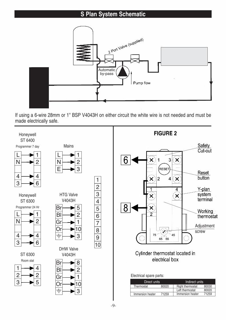
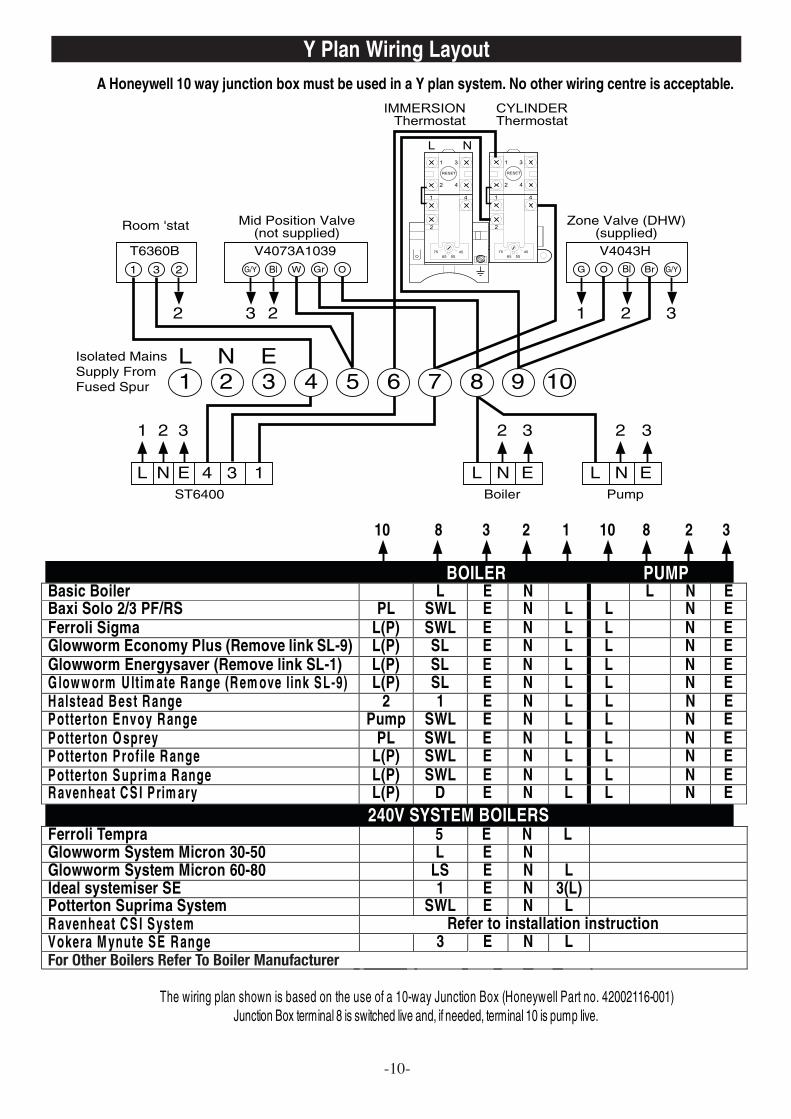
Indirect UnitsMotorised valveTo comply with regulations governing the installation of indirect unvented cylinders, a motorised valvemust be fitted in the primary flow. Your OSO unit has been supplied with a two port motorised valve,which will act as a positive energy cut-out should the safety cut-out operate. The motorised valve willalso control the temperature of the domestic stored water via the cylinder thermostat, which is locatedin the electrical box. The unit should be installed on an “S” or “Y” plan system. Please follow theinstructions carefully. All electrical connections must conform to current IEE wiring regulations. Theworking thermostat which controls the temperature of the domestic hot water (see fig. 2) is adjustablebetween 40°C - 70°C. A safety cut-out is also incorporated within the thermostat and will operate at85°C ± 3°C. Should the safety cut-out be brought into operation, the motorised valve will operate andclose down the primary flow to the cylinder. To reset the safety cut-out and the motorised valve thereset button must be pressed in (see fig. 2). If using a 6-wire 28mm or 1'' BSP V4043H on either circuitthe white wire is not needed and must be made electrically safe.
OSO Hotwater (UK) Limited can not be responsible if alternative wiring plans are used.Important: Before resetting the safety cut-out or altering the thermostat setting isolateelectrical supply to the unit before removal of the lid.
ELECTRICAL INSTALLATION
-7-
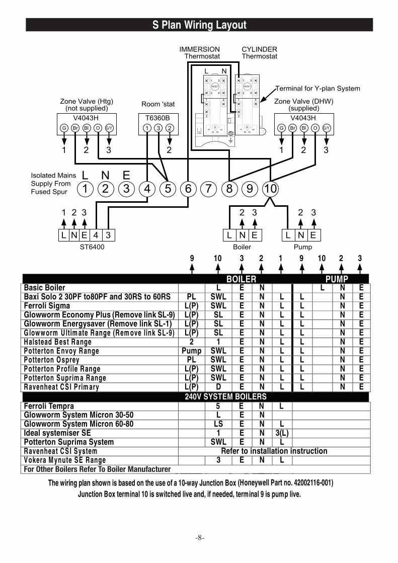
For Other Boilers Refer To Boiler Manufacturer
S Plan Wiring Layout
-8-
Thermostat 80020
Immersion heater 71259
Right thermostat 80030Left thermostat 80020Immersion heater 71259
Electrical spare parts:
S Plan System Schematic
If using a 6-wire 28mm or 1'' BSP V4043H on either circuit the white wire is not needed and must bemade electrically safe.
LN
43
12
46
LN
43
12
46
123
425
LNE
123
BrBlGrOr
521
103
BrBlGrOr
821
103
12345678910
-9-
HoneywellST 6400
Programmer 7 day
HoneywellST 6300
Programmer 24 Hr
ST 6300Room stat
Mains
HTG ValveV4043H
DHW ValveV4043H
Direct units Indirect units
Adjustmentscrew
Automatic by-pass
For Other Boilers Refer To Boiler Manufacturer
Y Plan Wiring Layout
-10-

Y Plan System Schematic
If using a 6-wire 28mm or 1'' BSP V4043H on either circuit the white wire is not needed and must bemade electrically safe.
-11-
Mid position Valve (not supplied)
LN413
12476
HoneywellST 6400
Programmer 7 day
LN413
12476
HoneywellST 6300
Programmer 24Hr
123
425
LNE
123
WGOBl
57823
BrBlGrOr
92183
ST 6300Room stat
Mains
V4073A1039
DHW ValveV4043H
12345678910
Automatic by-pass

OSO FAULT FINDING GUIDE
-12-
FAULT
NOTE: Disconnect electrical supply before removing any electrical equipment covers
POSSIBLE CAUSE REMEDY
No water flow from hot taps 1. Mains supply off.2. Strainer blocked.
3. Cold water inlet Pressure Reducing Valve incorrectly fitted.
1. Check and open stopcock2. Turn off water supply. Remove
strainer and clean. (See Pressure Reducing Valve page 6 Installation Manual)
3. Check and refit as required, (see item 3 page 5 of installation manual).
Water from hot taps is cold. 1. Immersion heaters not switched on.
2. Immersion heater thermal cut-out has operated.
3. Programmer set to central heating or not switched on.
4. Boiler not working.
5. Cylinder thermal cut-out has operated. (Indirect units only).
6. Motorised valve not operating correctly.
1. Check and switch on.
2. Check and reset button. (See thermostat diagram page 9 and safety cut-out on page 4 of installation manual).
3. Check and set to hot water.
4. Check boiler operation. If fault suspected consult installer or boiler manufacturer.
5. As at No. 2.
6. Check wiring and / or plumbing connections to motorised valve. (See pages 8or 10 of the installation manual).
Intermittent water discharge. 1. Reduced internal expansion.
2. Thermal control failure.(Note Water will be hot).
1. Recharge “air gap” (See cold water discharge on page 4 of installation manual).
2. Switch off power to immersion heater(s) and boiler supply to the unit. When discharge has stopped, check thermal controls, replace if faulty.Contact a competent person.
Continuous water discharge. 1. Cold water inlet Pressure Reducing Valve not working.
2. Temperature and pressure relief valve faulty.
3. Expansion relief valve not working correctly.
1. Check pressure from valve if greater than 2.1 bar replace. (See page 6 of installation manual).
2. As No. 2 of above.
3. Check and replace if faulty. (See page 6 of installation manual).

OSO FAULT FINDING GUIDE
OSO FAULT FINDING GUIDE
No water flow from hot taps
Reduced Internalexpansion volume
Thermal controlfailure
Recharge “air gap”.Follow correct
procedure
Switch off power toimmersion heaters and boiler supply to the unit.
When discharge hasstopped check thermal controls and replace as
necessary
If problem still persistscontact a competentengineer / plumber
Intermittent water discharge
If problem still persistscontact a competent
engineer
Mains supply off Line strainerblocked
Cold water PRVincorrectly fitted
Open supplyvalve
Clear linestrainer
Check and refitas required
YES YES
NO NO
YESYESYES
NO
-13-

-14-
OSO FAULT FINDING GUIDE
Excessive Hot water from taps
If in doubt at any stage you must consult a qualified electrician
Hot water from taps is cold
If problem still persistscontact a competentengineer / plumber
Are immersionheaters switched
on
Switch onimmersion
heaters
Has immersionheater thermal
cut-out operated?
Check andreset
button
Is the programmer set tocentral heating ornot switched on
Check andset to hot
waterprogramme.
Is themotorised
valveoperatingcorrectly?
Check wiringor plumbingconnections
Check andreset
button
Has cylinderthermal cut-out
operated?
Is the boilerworking?YES NO
NO YES
NO
YESYES
YES YES
NO
DDIIRREECCTT IINNDDIIRREECCTT
Cylinder Thermostatset to high
Connect wiring asper instructions
Faultythermostat
replace
Check wiringon cylinderthermostat
Wiring FaultSeek advice
fromelectrician
Is Thermostat wiredas per layouts for
“S” or “Y” planinstallation
Is 2-port motorisedvalve closing when
cylinder reachestemperature?
Check cylinderthermostat is switching
on & off withprogrammer & hot water
on
ReduceTemperature setting
YES
NO
NO
YES
NO
NO
YES
YES
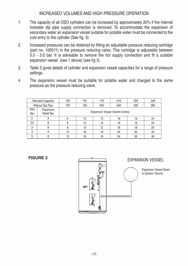
INCREASED VOLUMES AND HIGH PRESSURE OPERATION
1. The capacity of all OSO cylinders can be increased by approximately 20% if the internalhotwater dip pipe supply connection is removed. To accommodate the expansion ofsecondary water an expansion vessel suitable for potable water must be connected to thecold entry to the cylinder (See fig. 3).
2. Increased pressures can be obtained by fitting an adjustable pressure reducing cartridge(part no. 100511) in the pressure reducing valve. This cartridge is adjustable between 0.5 - 5.0 bar. It is advisable to remove the hot supply connection and fit a suitableexpansion vessel. (see 1 above) (see fig 3)
3. Table 3 gives details of cylinder and expansion vessel capacities for a range of pressuresettings.
4. The expansion vessel must be suitable for potable water and charged to the samepressure as the pressure reducing valve.
Standard Capacity 100 125 170120 150 200
8 12 128 12 128 12 1212 18 1912 18 19
210
250
1818182424
250
300
1818183030
330
380
2424244040
Without Dip PipePRVBar
22.5345
88888
ExpansionRelief Bar Expansion Vessel Volume (Litres)
-15-
FIGURE 3 EXPANSION VESSEL
Expansion Vessel Sizedto System Volume

Where a single pipe serves a number of discharges,such as in blocks of flats, the number served shouldbe limited to not more than 6 systems so that anyinstallation discharging can be traced reasonablyeasily. The single common discharge pipe should beat least one pipe size larger than the largestindividual discharge pipe to be connected. For furtherinformation contact your Building Control Office orThe British Board of Agrément.
Discharge at high level, i.e. into a metal hopper andmetal down pipe with the end of the discharge pipeclearly visible (tundish visible or not) or onto a roofcapable of withstanding high temperature dischargesof water and 3m from any plastics guttering systemthat would collect such discharges (tundish visible).
-16-
ALTERNATIVE DISCHARGE
SECONDARY RETURN
Downward discharges at low level, i.e. up to 100mm above external surfaces such as car parks, hardstandings, grassed areas etc, are acceptable providing that where children may play or otherwisecome into contact with discharges, a wire cage or similar guard is positioned to prevent contact, whilstmaintaining visibility.
5
6
4 3
21
HOT TAPSHOT OUTLET COLD INLET
FIGURE 4
FIGURE 5
1 Secondary Return Fitting use 1/2''F x 1/2'' M x 15mm Tee (not supplied)2 Commissioning Valve3 Non Return Valve4 Circulation Pump5 Secondary Return Line6 Balanced cold supply for showers or bidet only
OSO HOTWATER (UK) LTD www.oso-hotwater.comE15 Marquis CourtTeam Valley Trading EstateGatesheadTyne & Wear, NE11 0RU E-mail [email protected]
Phone: (0191) 482 0800 E-mail [email protected]: (0191) 491 3655 E-mail [email protected]
All replacement parts must be supplied by OSO HOTWATER (UK) LIMITED.To obtain the address of a local stockist contact:
![Rotationally Moulded Sandwich Composites in Small …eprints.bournemouth.ac.uk/24671/2/Presentation%20Abu%20for%20RI… · Tensile, flexural, impact properties are tested [6]. ...](https://static.fdocuments.in/doc/165x107/5b796e2f7f8b9a7f378da1e4/rotationally-moulded-sandwich-composites-in-small-20abu20for20ri-tensile.jpg)