2012 PHYSICS UNIT 3 Written examination 1 -...
47
This trial examination produced by Insight Publications is NOT an official VCAA paper for the 2012 Physics written examination 1. This examination paper is licensed to be printed, photocopied or placed on the school intranet and used only within the confines of the purchasing school for examining their students. No trial examination or part thereof may be issued or passed on to any other party including other schools, practising or non-practising teachers, tutors, parents, websites or publishing agencies without the written consent of Insight Publications. Copyright © Insight Publications 2012 INSIGHT YEAR 12 Trial Exam Paper 2012 PHYSICS UNIT 3 Written examination 1 Worked Solutions This book presents: worked solutions, giving you a series of points to show you how to work through the questions mark allocation details tips
Transcript of 2012 PHYSICS UNIT 3 Written examination 1 -...

This trial examination produced by Insight Publications is NOT an official VCAA paper for the 2012 Physics written examination 1. This examination paper is licensed to be printed, photocopied or placed on the school intranet and used only within the confines of the purchasing school for examining their students. No trial examination or part thereof may be issued or passed on to any other party including other schools, practising or non-practising teachers, tutors, parents, websites or publishing agencies without the written consent of Insight Publications. Copyright © Insight Publications 2012
INSIGHT YEAR 12 Trial Exam Paper
2012
PHYSICS
UNIT 3
Written examination 1
Worked Solutions
This book presents:
worked solutions, giving you a series of points to show you how to work through the questions
mark allocation details tips

2
SECTION A – Area of study 1 – continued Copyright © Insight Publications 2012
SECTION A – Core
Area of study 1 – Motion in one and two dimensions
The following information relates to Questions 1–4.
Figure 1 A truck of mass 2.5 tonnes is attached to two trailers, each of mass 3 tonnes as shown in Figure 1. There are frictional forces acting of 0.25 N kg–1, which remain constant. The truck accelerates at a constant rate of 0.75 m s–2 from rest until it reaches the speed limit of 60 km h–1. Question 1
What is the magnitude of the net force on the system of the truck and trailers while the truck accelerates?
Worked solution
ΣF ma
= (8500) (0.75)
= 6375 N
2 marks Mark allocation
1 mark for correct substitution.
1 mark for correct answer.
6375 N
Second trailer 3 tonnes
First trailer 3 tonnes
Truck 2.5 tonnes

3
SECTION A – Area of study 1 – continued TURN OVER
Copyright © Insight Publications 2012
Question 2
What is the driving force provided by the truck engine to propel the load forwards while accelerating?
Tip Resolve forces into components.
Worked solution
ΣF = driving force + frictional force
6375 = Fd – (0.25 × 8500)
6375 = Fd – 2125
Fd = 6375 + 2125
Fd = 8500 N
2 marks Mark allocation
1 mark for correct substitution.
1 mark for correct answer.
8500 N

4
SECTION A – Area of study 1 – continued Copyright © Insight Publications 2012
Question 3
Calculate the tension between the second and first trailers while the truck is accelerating.
Tip
Treat second trailer as an isolated system.
Worked solution
F2nd trailer = T + Ffriction
ma = T – 750
3000 × 0.75 = T – 750
2250 = T – 750
T = 3000 N
2 marks Mark allocation
1 mark for finding resultant force on trailer.
1 mark for correct answer.
3000 N
Second trailer 3 tonnes
T
a
750 N

5
SECTION A – Area of study 1 – continued TURN OVER
Copyright © Insight Publications 2012
Question 4
How long would it take for the truck to reach the legal speed limit of 60 km h–1, at which time it will stop accelerating?
Tip Consider acceleration to be constant throughout the process.
Worked solution
u 0 m s–1
v = 60 km h–1 16.67 m s–1
a 0.75 m s–2
t ?
v u + at
16.67 0 + (0.75)t
t 22.22 s
2 marks
Mark allocation
1 mark for converting km h–1 into m s–1.
1 mark for correct answer.
22.22 s

6
SECTION A – Area of study 1 – continued Copyright © Insight Publications 2012
The following information relates to Questions 5–8.
During a NASCAR race, a driver and his racing car have a combined mass of 2500 kg. At a particular circular section of the track, which is inclined at an angle θ to the horizontal, the car is travelling at a constant speed of 50 m s–1 around a radius of 150 m. Ignore retarding friction.
Figure 2
Question 5
What is the magnitude of the net force on the driver and car?
Worked solution
2
2
4
Σ
2500 50
150
41666.7
4.2 10 N
mvF
R
2 marks Mark allocation
1 mark for correct substitution.
1 mark for correct answer.
4.2 × 10⁴ N
7
SECTION A – Area of study 1 – continued TURN OVER
Copyright © Insight Publications 2012
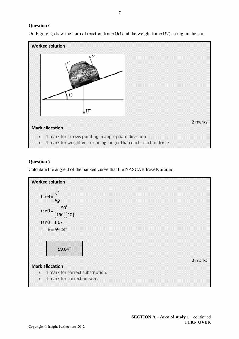
Question 6
On Figure 2, draw the normal reaction force (R) and the weight force (W) acting on the car. Question 7
Calculate the angle θ of the banked curve that the NASCAR travels around.
Worked solution
2 marks Mark allocation
1 mark for arrows pointing in appropriate direction.
1 mark for weight vector being longer than each reaction force.
Worked solution
2
2
tanθ
50tanθ
150 10
tanθ 1.67
θ 59.04
v
Rg
2 marks Mark allocation
1 mark for correct substitution.
1 mark for correct answer.
59.04°

8
SECTION A – Area of study 1 – continued Copyright © Insight Publications 2012
Question 8
Explain the purpose of having banked curves.
Worked solution
Banked curves allow the car to travel faster. The maximum centripetal force is the sum of the frictional force due to the road and normal component acting towards the centre of motion.
2 marks Mark allocation
1 mark for each correct response.

9
SECTION A – Area of study 1 – continued TURN OVER
Copyright © Insight Publications 2012
The following information relates to Questions 9–13.
A basketball of mass 1.5 kg strikes a wall at 10 m s–1 horizontally and rebounds at 8 m s–1 horizontally. The collision between the ball and the wall lasts for 0.1 seconds. This situation is shown in Figure 3.
Figure 3 Question 9
What is the change in speed of the ball after the collision?
Tip Speed is a scalar quantity.
Worked solution
f i
1
1
8 10
= 2 m s
or
= 2 m s
v v v
2 marks
Mark allocation
2 marks for correct answer.
2 m s–1

10
SECTION A – Area of study 1 – continued Copyright © Insight Publications 2012
Worked solution
.
1
1
Δ final momentum ‐ initial momentum
1 5 8 10
27 kg m s
or
= 27 kg m s
mv mu
m v u
2 marks
Mark allocation
1 mark for correct substitution.
1 mark for correct answer.
Worked solution
2 marks
Mark allocation
1 mark for each correct response.
Question 10
Calculate the magnitude of the change in momentum of the ball.
Tip Momentum is a vector quantity and direction is in the same direction as
acceleration.
Question 11
What is the average force the wall exerts on the ball? Also indicate the direction of the force.
–1 –1Change in momentum of ball is – 27 kg m s or 27 kg m s
0.1 27
270 N
i.e. Force 270 N Direction = left
I Ft p
F
F
Tip Change in momentum is equal to impulse.
270 N Direction = left
27 kg m s–1

11
SECTION A – Area of study 1 – continued TURN OVER
Copyright © Insight Publications 2012
Worked solution
Newton’s third law applies, i.e. force equal and opposite. Force = 270 N Direction = right
2 marks Mark allocation
1 mark for each correct response.
Question 12
What is the force the ball exerts on the wall? Also indicate direction.
Tip Newton’s third law applies to all objects.
Question 13
Using calculations, show if the collision is inelastic.
Tips Most collisions are inelastic. Momentum is conserved in all collisions. The sum of the final kinetic energy cannot be greater than the initial in such
collisions.
270 N Direction = right
Worked solution
2
2
1initially before collision
21 × 1.5 × 10
275 J
mv
2
2
1finally after collision
21
= × 1.5 × 8248 J
mv
inelastic. before collision after collision so collision is 2 marks
Mark allocation
1 mark for calculating both final and initial kinetic energy.
1 mark for stating collision is inelastic.

12
SECTION A – Area of study 1 – continued Copyright © Insight Publications 2012
Sean takes a ride in a cart at a theme park. The combined mass of Sean and the cart is 200 kg. He begins from rest (point A) at a height of 80 m above the ground (Figure 4).
Figure 4 Question 14
Calculate Sean’s speed at point B, if frictional forces are ignored.
Tip Energy is never lost, just transformed to other forms.
Worked solution
2
2
2
1
at point B total energy at point A
1 from A to B
21
2
2 10 80
1600
40 m s
mv
mv mgh
v
v
2 marks
Mark allocation
1 mark for calculation.
1 mark for correct answer.
40 m s–1

13
SECTION A – Area of study 1 – continued TURN OVER
Copyright © Insight Publications 2012
Question 15
After point B, friction is introduced in order to bring the cart and Sean to rest at point C. If the distance between point B and C is 40 m, calculate the deceleration of the cart.
Tip Work done can equal change in kinetic or potential energy.
Worked solution
u 40 m s –1 v 0 m s–1 s 40 m a ? v2 u2 + 2as 02 402 + 2a(40) a –20 m s–2 or
W Fs 1.6 x 105 F x 40 F 4000 N F ma
∴ 4000 20 x a a 20 m s–2
2 marks
Mark allocation
1 mark for calculation.
1 mark for correct answer.
20 m s–2

14
SECTION A – Area of study 1 – continued Copyright © Insight Publications 2012
Worked solution
2 marks
Mark allocation
1 mark for correct substitution.
1 mark for correct answer.
Question 16
A spring-loaded gun fires 10 g bullets at a speed of 100 km h–1. If the spring is compressed by 20 cm, calculate its spring constant.
2 2
2 2
1
energy stored in spring
1 1
2 21 1
0.01 27.78 0.22 20.02 3.8586
192.9 m
mv kx
k
k
k
Tip Elastic potential energy has been converted to kinetic energy. 100 km h–1 =27.78 m s–1.
192.9 N m–1

15
SECTION A – Area of study 1 – continued TURN OVER
Copyright © Insight Publications 2012
Question 17
Malcolm takes a set shot 50 m from goal (Figure 5). He realises that to clear the last defender, the ball needs to have a minimum height of 3 m at the goal line. If he kicks the ball at 24 m s–1 from ground level at an angle of 45° to the horizontal, assuming he is accurate, does he kick a goal? Use calculations to explain your answer.
Figure 5
Tips Time of flight is determined by vertical components. Horizontal velocity is constant in the absence of air resistance. Gravity only influences vertical components.
Worked solution Time to reach goal determined by horizontal component:
h
range 50
u 16.97
2.95 s
t
t
Require vertical height of ball after 2.95 seconds.
2
2
1
21
16.97 2.95 10 2.952
50 43.51
6.49 m
s ut at
The ball is well above the minimum 3 metres height. YES
3 marks Mark allocation
1 mark for calculating time of flight.
1 mark for calculation to derive correct answer.
1 mark for correct answer.
6.49 m Yes / No
24 m s–1
°
16
SECTION A – Area of study 1 – continued Copyright © Insight Publications 2012
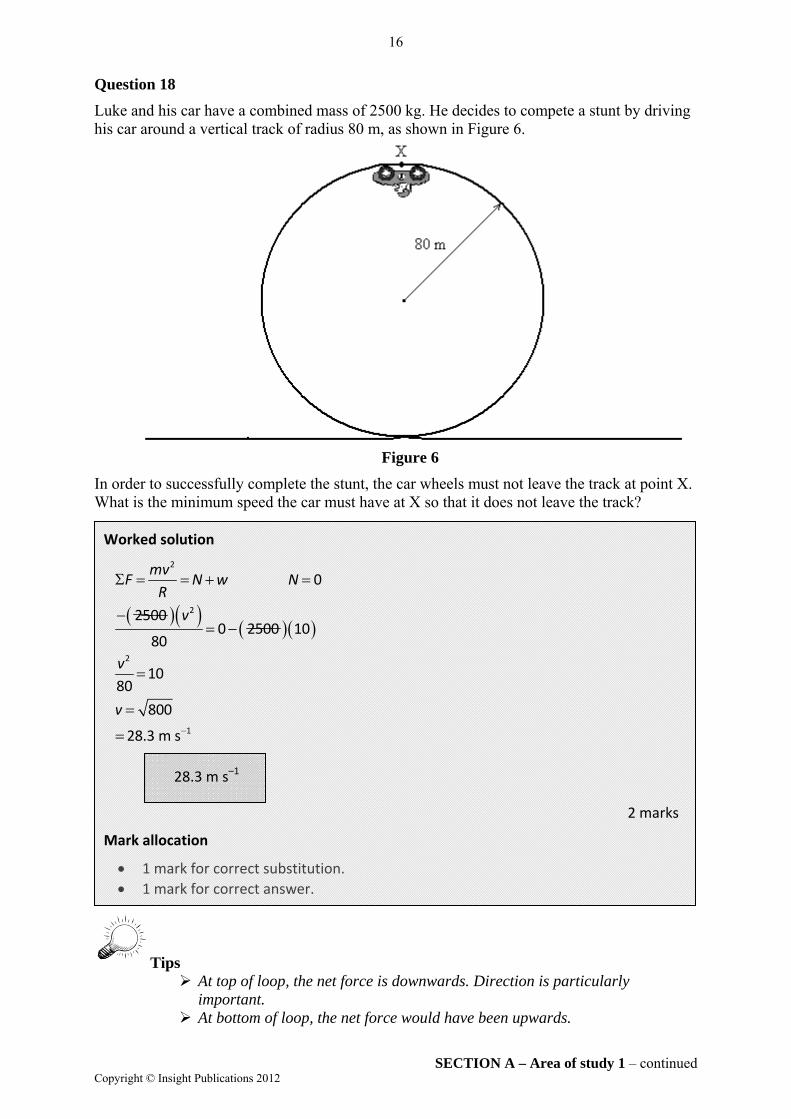
Question 18
Luke and his car have a combined mass of 2500 kg. He decides to compete a stunt by driving his car around a vertical track of radius 80 m, as shown in Figure 6.
Figure 6
In order to successfully complete the stunt, the car wheels must not leave the track at point X. What is the minimum speed the car must have at X so that it does not leave the track? Worked solution
2
2
2
1
0
25000 2500 10
80
1080
800
28.3 m s
mvF N w N
R
v
v
v
2 marks
Mark allocation
1 mark for correct substitution.
1 mark for correct answer.
Tips At top of loop, the net force is downwards. Direction is particularly
important. At bottom of loop, the net force would have been upwards.
28.3 m s–1

17
SECTION A – Area of study 1 – continued TURN OVER
Copyright © Insight Publications 2012
The following information relates to Questions 1–22.
The secret satellite ‘SPY’ has a circular orbit of radius 1.50 × 10⁷ m and a mass of 1000 kg.
Figure 7 Question 19
On Figure 7 above, draw one or more arrows to indicate the direction of any force acting on the satellite SPY.
Worked solution
1 mark
Mark allocation
1 mark for arrow

18
SECTION A – Area of study 1 – continued Copyright © Insight Publications 2012
Question 20
What is the weight of the satellite SPY in its orbit? Worked solution
2
11 24
27
6.67 10 5.98 10 1000
1.5 10
1772.7 N
GMmF
R
2 marks Mark allocation
1 mark for correct substitution.
1 mark for correct answer. Question 21
What is the period of orbit of the satellite around Earth?
Worked solution
2 3
32 7
11 24
8
4
4π
4π 1.5 10
6.67 10 5.98 10
3.34 10
1.83 10 s
RT
GM
2 marks Mark allocation
1 mark for correct substitution.
1 mark for correct answer.
1772.7 N
1.83 104 s

19
END OF AREA OF STUDY 1 SECTION A – continued
TURN OVER Copyright © Insight Publications 2012
Question 22
An astronaut repairing the satellite while in orbit believes he is weightless. Is his assumption correct? Explain your answer. Worked solution
No
He is not weightless as gravity acts on him.
He is experiencing apparent weightlessness.
Apparent weightlessness occurs when N = 0. 2 marks
Mark allocation
1 mark for stating ‘No’.
1 mark for any correct explanation.
END OF AREA OF STUDY 1

20
SECTION A – Area of study 2 – continued Copyright © Insight Publications 2012
Area of study 2 – Electronics and photonics
The following information relates to Questions 1–4.
Luke sets up the circuit shown in Figure 1.
Figure 1 Question 1
Calculate the total resistance of the circuit. Show your working. Worked solution
Resistances in parallel:
parallel
parallel
t parallel series
1 1 1 2 1 =
3 6 6 6
6 2
3
2 2 1 5
R
R
R R R
2 marks Mark allocation
1 mark for calculation.
1 mark for correct answer.
Tips Calculate resistance in each branch, then apply resistors in parallel. Combination circuit.
5 Ω

21
SECTION A – Area of study 2 – continued TURN OVER
Copyright © Insight Publications 2012
Question 2
What is the reading on the ammeters? Worked solution
t t t
t
t
1 3
10 5
2 A
A A 2 A
V I R
I
I
For A2, using ratios:
t
2
1 12
3 3
A 0.7 A
I
3 marks Mark allocation
1 mark for each correct response.
Tip More current flows through branch that has least resistance.
Question 3
What is the potential difference across the 1 Ω resistor?
Worked solution
V = IR = 2 × 1 = 2 V
2 marks Mark allocation
1 mark for calculation.
1 mark for correct response.
A1 = 2 A A2 = 0.7 A A3 = 2 A
2 V

22
SECTION A – Area of study 2 – continued Copyright © Insight Publications 2012
Question 4
What is the power across the 3 Ω resistor?
Worked solution
44
3
5.3 W
P VI
2 marks Mark allocation
1 mark for calculation.
1 mark for correct response.
The following information relates to Questions 5 & 6. Quang sets up the circuit shown in Figure 2 using two identical LEDs and an 18 Ω resistor. The I–V characteristics of the diodes are shown in Figure 3.
Figure 2 Figure 3
5.3 W
LED1
LED2
I (mA)
V (volts)

23
SECTION A – Area of study 2 – continued TURN OVER
Copyright © Insight Publications 2012
Question 5
What is the power rating across LED1? Show your working.
Question 6
Quang decides to reverse LED1 and measure the potential difference across it. What is the reading on the voltmeter? Explain your answer.
Tip When LED is reversed, it has infinite resistance and maximum p.d.
Worked solution
LED
VRes V
V IR I
I A
P VI W
10 0.5 0.5 9
9 18
18 0.5
9 0.5 0.5 025
3 marks
Mark allocation
1 mark for p.d. across resistor.
1 mark for current of 0.5 A.
1 mark for answer of 0.25 W.
0.25 W
Worked solution
When LED1 is reversed, it has infinite resistance and maximum p.d.
2 marks Mark allocation
2 marks for correct answer.
p.d. = 10 V

24
SECTION A – Area of study 2 – continued Copyright © Insight Publications 2012
The following information relates to Questions 7–10.
The temperature-resistance characteristics of a thermistor are shown in Figure 4.
Figure 4
Question 7
What is the resistance of the thermistor at 5°C?
0
100
200
300
400
500
600
700
800
900
1000
0 5 10 15 20 25 30 35
Resistance (Ω)
Temperature (°C)
Solution
1 mark Mark allocation
1 mark for correct answer.
500 Ω
25
SECTION A – Area of study 2 – continued TURN OVER
Copyright © Insight Publications 2012
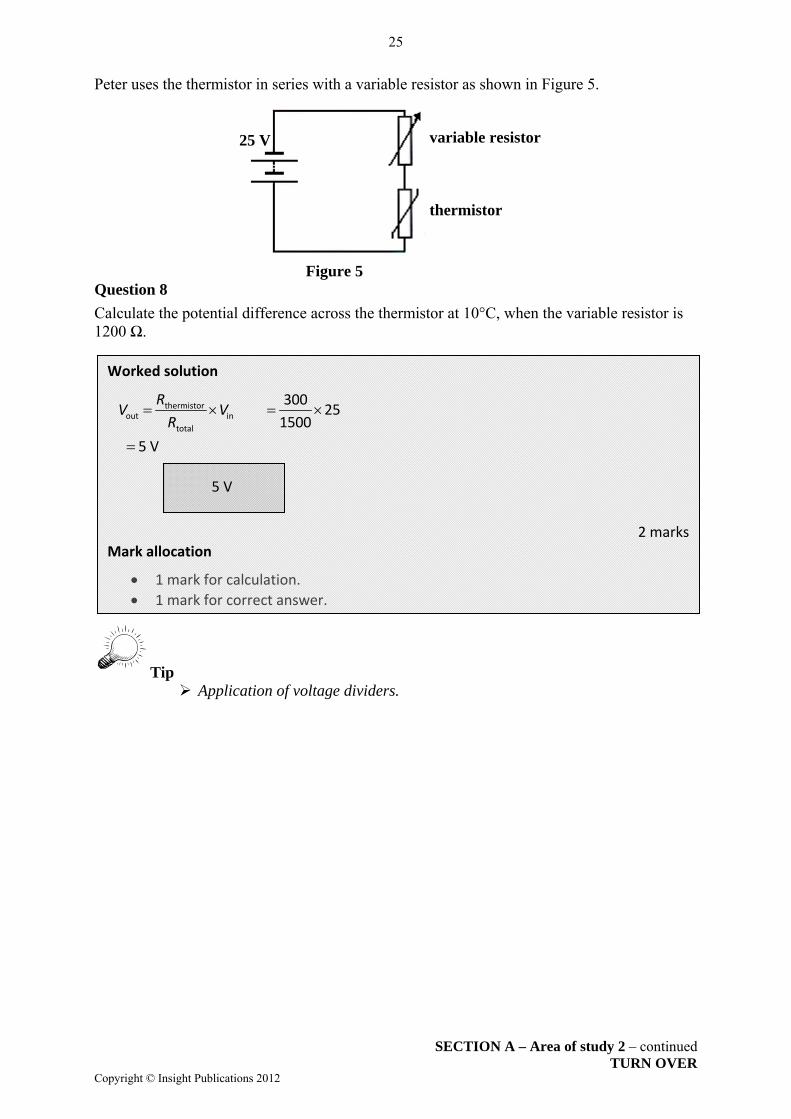
Peter uses the thermistor in series with a variable resistor as shown in Figure 5.
Figure 5 Question 8
Calculate the potential difference across the thermistor at 10°C, when the variable resistor is 1200 Ω.
Tip Application of voltage dividers.
Worked solution
thermistorout in
total
300 25
1500
5 V
RV V
R
2 marks Mark allocation
1 mark for calculation.
1 mark for correct answer.
5 V
variable resistor
thermistor
25 V
26
SECTION A – Area of study 2 – continued Copyright © Insight Publications 2012
Peter wants to use the circuit as an input switch to a heater. The heater will switch on when the input of the switch is 5 V or more.
Question 9
Where should the input of the heater be placed: across the thermistor or across the 1200 Ω resistor? Explain your answer.
Question 10
Peter wants the heater to switch on when the temperature drops below 15°C. Should the variable resistor be increased or decreased to achieve this? Explain your answer.
Tips Consider what occurs when there is a change in resistance. Ratio of potential difference across each resistor needs to be maintained. Apply voltage divider mentally.
Solution
The switch should be placed across the thermistor. As temperature decreases, the resistance of the thermistor increases, thus there is greater p.d. across the thermistor. You don’t want the heater coming on when the temperature increases, which would occur if it was placed across the variable resistor.
3 marks
Mark allocation
1 mark for each of the above points.
Solution
Input of switch remains at 5 V to switch on. At 10°C, the resistance of the thermistor is 300 Ω, in comparison to at 15°C, when the resistance of the thermistor is less than 200 Ω. The ratio across the thermistor and variable resistor needs to be maintained. The value of the variable resistor needs to be decreased.
3 marks Mark allocation
1 mark for the above points, maximum of three marks.

27
END OF SECTION A TURN OVER
Copyright © Insight Publications 2012
Question 11
A voltage amplifier has the characteristics shown in Figure 5. The input signal is displayed in Figure 6.
Figure 5 Figure 6 Draw the output signal and include values on your axes.
Worked solution
show clipping at +5 V and 5 V frequency the same invert signal
3 marks Mark allocation
1 mark for clipping. 1 mark for frequency. 1 mark for inverting signal.
t(ms)
Vout (V)
Vin (mV)
Vout (V)
Vin (mV) t (ms)
–15
15
28
SECTION B – Detailed study 1 – continued Copyright © Insight Publications 2012
SECTION B – Detailed studies
Detailed study 1 – Einstein’s special relativity
Question 1
When Einstein’s equation E mc2 is applied to an electron with mass ‘m’, which of the following is true?
A. Electrons travelling at high speeds convert their energy into light, according to E mc2.
B. Electrons have no energy since their mass is extremely small.
C. Electrons have an energy of E, purely because of their existence.
D. Einstein’s relativity does not apply to quantum particles.
Question 2
The mass of an electron at rest is 9.1 × 10⁻³¹ kg according to Einstein’s special theory of relativity. This is equivalent to an energy of:
A. 0 J
B. 9.1 × 10⁻³¹ J
C. 4.1 × 10¹⁴ J
D. 8.2 × 10⁻¹⁴ J
Tip Application of E mc2.
Question 3
An electron accelerator can accelerate an electron to a speed that will increase its mass by a factor of 22. As the electron leaves the accelerator, what is the value of the Lorentz factor?
A. 11
B. 22
C. 44
D. 220
Answer is C.
Answer is D.
Worked solution
[E mc2] E (9.1 × 10⁻³¹)(3 × 10⁸)2 = 8.2 × 10⁻¹⁴ J
Answer is B.

29
SECTION B – Detailed study 1 – continued TURN OVER
Copyright © Insight Publications 2012
The following information relates to questions 4 & 5.
A radioactive particle in an accelerator is found to have a half-life of 20 seconds when travelling at 0.8c and is observed by a stationary scientist. Question 4
What is the particle’s half-life in its own frame of reference?
A. 20 s
B. 12 s
C. 40 s
D. 10 s
Question 5
The radioactive particle is inside a detector of length 8 m. From the particle’s frame of reference, how long is the detector?
A. 4.8 m
B. 4.0 m
C. 8.0 m
D. 13.3 m
Answer is B.
Worked solution
t t t
1 2 2
0 0
γ 1 0.8 = 1.67
20 = γ = 12 s
1.67
Answer is A.
Worked solution
0 8 4.8 m
γ 1.67
LL

30
SECTION B – continued Copyright © Insight Publications 2012
This page is blank

31
SECTION B – Detailed study 1 – continued TURN OVER
Copyright © Insight Publications 2012
Question 6
Which of the following quantities is not affected by travel at speed close to the speed of light when measured by both stationary and moving observers?
A. speed of light
B. mass in kg
C. velocity
D. length
Tip Speed of light is independent of stationary and moving observers.
Question 7
An electron of mass 9.1 × 10⁻³¹ kg is accelerated across a potential of 20 MeV. The speed of this electron in Newtonian physics would be
A. 1.35 × 10⁷ m s–1
B. 2.65 × 10⁷ m s–1
C. 3.00 × 10⁸ m s–1
D. 2.65 × 10⁹ m s–1
Tip Excessive speed for electron.
Answer is A.
Answer is D.
Worked solution
6 19
9 1
31
2 20 10 1.6 102 2.65 10 m s
9.1 10
Ev
m

32
SECTION B – Detailed study 1 – continued Copyright © Insight Publications 2012
Question 8
At the Synchrotron an electron is accelerated to a speed of 2.5 × 10⁸ m s–1. The mass of such an electron measured by an observer would be
A. 9.1 × 10⁻³¹ kg
B. 3.2 × 10⁻³⁰ kg
C. 1.65 × 10⁻³⁰ kg
D. 9.1 × 10⁻³⁰ kg
Tip As velocity increases, the mass of the electron also increases.
Answer is C.
Worked solution
v
m m0
8
8
1 2 2
31 30
2.5 10 0.833 c
3 10
γ = 1 0.833 1.80
Heavier γ 9.1 10 1.80 1.65 10 kg

33
END OF DETAILED STUDY 1 SECTION B – continued
TURN OVER Copyright © Insight Publications 2012
The following information relates to questions 9 & 10.
A neutron of rest mass 1.675 × 10⁻²⁷ kg travels at 0.2c. Question 9
The momentum of the neutron would be
A. 8.350 × 10⁻²⁷ kg m s–1
B. 3.350 × 10⁻²⁸ kg m s–1
C. 1.675 × 10⁻¹⁹ kg m s–1
D. 1.026 × 10⁻¹⁹ kg m s–1
Question 10
The kinetic energy of the neutron would be
A. 8.35 × 10⁻¹² J
B. 3.10 × 10⁻¹² J
C. 3.35 × 10⁻¹² J
D. 1.69 × 10⁻¹² J
Answer is D.
Worked solution
12 2
227 80
19 1
γ 1 0.2 =1.021
γ 1.675 10 1.021 0.2 3 10
1.026 10 kg m s
P mv m v
Answer is B.
Worked solution
22 27 80
12
KE γ ‐1 1.021 1 1.675 10 3 10
3.10 10 J
M c

34
SECTION B – Detailed study 2 – continued Copyright © Insight Publications 2012
Detailed study 2 – Further electronics Question 1
An audio amplifier operates on a DC power supply, but the supply has an AC ripple component. The magnitude of the ripple voltage is best measured using
A. an oscilloscope
B. an ammeter
C. a voltmeter
D. a variable resistor
The following information relates to questions 2–4.
A regulated DC power supply is shown in Figure 1 below. The input voltage is from 6 V RMS AC supply. The AC power supply has an input supply of 240 V RMS.
Figure 1
Question 2
If the primary side of the transformer has 120 turns, how many turns are there on the secondary side of the transformer?
A. 40
B. 3
C. 6
D. 24
Tips Step-down transformer. Power of primary and secondary is equal.
Answer is A.
Answer is B.
Worked solution
s s ss
p p
6 = = = 3
120 240
N V NN
N V
240 V RMS AC input
transformer capacitor
regulated DC voltage output
bridge rectifier
voltage regulator
6 V AC output

35
SECTION B – Detailed study 2 – continued TURN OVER
Copyright © Insight Publications 2012
Question 3
If the current flowing in the primary coil is 0.1 A, what is the power supplied to the bridge rectifier, assuming the transformer is ideal?
A. 12 W
B. 6 W
C. 18 W
D. 24 W
Tip Ideal transformers assume no power loss, which is not realistic.
Question 4
What is the peak current supplied to the bridge rectifier?
A. 0.143 A
B. 1.43 A
C. 5.66 A
D. 2.83 A
Tip Beware of the difference between ‘peak to peak’ and simply ‘peak’ current.
Answer is D.
Worked solution
p s 240 0.01 24 W P P VI
Answer is C.
Worked solution
pss
p s
s s
240 = = = 4 A
0.1 6
peak = 2 = 5.66 A
sVI I
II V
I I

36
SECTION B – Detailed study 2 – continued Copyright © Insight Publications 2012
The following information relates to Questions 5 & 6
A full-wave bridge rectifier is to be used in a circuit that produces DC from an AC input.
Question 5
Which of the following circuits would be most suitable?
Tip Diodes only allow current to flow through them when forward biased.
Vin
Vin Vin
VinVoutVout
Vout Vout
Answer is C.
Explanatory note
Only correct option.

37
SECTION B – Detailed study 2 – continued TURN OVER
Copyright © Insight Publications 2012
Question 6
With the rectifier correctly connected and functioning, which of the following signals would be observed if an oscilloscope was connected across the output (Vout) of the bridge rectifier?
Answer is B.
Explanatory note
Full‐wave rectifier.

38
SECTION B – Detailed study 2 – continued Copyright © Insight Publications 2012
The following information relates to Questions 7 & 8.
Malcolm uses an oscilloscope to test a circuit. He connects the oscilloscope to an AC signal generator. The vertical scale is set on 4 V cm–1, and the horizontal scale on 40 ms cm–1. He observes the display on the oscilloscope, as shown below in Figure 2.
Figure 2
Question 7
Which of the following best gives the correct value of the peak-to-peak voltage of the AC signal generator?
A. 14 V
B. 20 V
C. 7 V
D. 28 V
Tips Need to count squares accurately. Vertical axis represents voltage.
Answer is D.
Worked solution
14 V cm 7 cm 28 V

39
SECTION B – Detailed study 2 – continued TURN OVER
Copyright © Insight Publications 2012
Question 8
Which one of the following best gives the frequency from the signal generator?
A. 6.25 Hz
B. 4 Hz
C. 16 Hz
D. 13.5 Hz
Tips Application of waves. Frequency is the number of cycles per second.
Answer is A.
Worked solution
3
1 =
1 =
160 10
= 6.25 Hz
fT

40
SECTION B – Detailed study 2 – continued Copyright © Insight Publications 2012
The following information relates to Questions 9 & 10.
Nabilla studies the voltage–current characteristics of a zener diode as shown in Figure 3.
Figure 3
Nabilla places the zener diode in the circuit as shown in Figure 4.
Figure 4
Question 9
The voltage Nabilla measured across R1 is?
A. 4 V
B. 6 V
C. 0.6 V
D. 12 V
Answer is B.
Worked solution
Diode is reverse biased and p.d. will be 4 V across it. 10 – 4 = 6 V across R1.
V (volts)

41
END OF DETAILED STUDY 2 SECTION B – continued
TURN OVER Copyright © Insight Publications 2012
Question 10
What will be the current across the zener diode?
A. 0.105 A
B. 0.011 A
C. 0.116 A
D. 0.120 A
Tips Total current in series remains constant. Current splits accordingly at parallel part of circuit.
Answer is C.
Worked solution
I
I
1 1
2 2
6Current through R : = 0.12 A
50
4Current through R : = 0.004 A
1000
Current through diode = 0.12 ‐0.004 = 0.116 A

42
SECTION B – Detailed study 3 – continued Copyright © Insight Publications 2012
Detailed study 3 – Materials and their use in structures
The following information relates to Questions 1–5. A group of students are testing the tensile strength of three different materials. Each material has a length of 5.00 m exactly when no tension is applied. The materials are labelled as 1, 2 and 3 on the graph below (Figure 1). The letter B represents the point where the material breaks.
Figure 1
Question 1
Which of the following is the best estimate of Young’s modulus for material 2?
A. 2.5 × 10¹¹ N m–2
B. 5 × 10⁶ N m–2
C. 2 × 10⁻³ N m–2
D. 4 × 10⁻⁹ N m–2
Tip Note units on vertical and horizontal axes.
Answer is A.
Worked solution
69
3
11 2
σ 500 10 = = = 250 10
ε 2 10
2.5 10 N m
E
Strain (× 103)
Stress (MPa)
43
SECTION B – Detailed study 3 – continued TURN OVER
Copyright © Insight Publications 2012
Question 2
Material 1 breaks when the force applied to it is 1.5 × 10⁵ N. This indicates that it would have a cross-sectional area of
A. 4.50 × 10⁻³ m2
B. 6.00 × 10⁻³ m2
C. 3.75 × 10⁻⁴ m2
D. 2.50 × 10⁻⁴ m2
Tip Read graph carefully.
Question 3
What is the length of material 1 when it breaks?
A. 5.500 m
B. 5.005 m
C. 5.050 m
D. 4.995 m
Answer is C.
Worked solution
F
A A
A
56
54 2
6
1.5 10σ 400 10
1.5 10 3.75 10 m
400 10
Answer is B.
Worked solution
m
length m
1 1ε 1
1
3 3Δ1 10 5 10 0.005
5.00
5.005
44
SECTION B – Detailed study 3 – continued Copyright © Insight Publications 2012
Question 4
Comparing the three materials, which statement is true regarding strength and toughness?
A. 1 is the strongest and 3 is the toughest.
B. 1 is the toughest and 2 is the strongest.
C. 2 is the toughest and the strongest.
D. 2 is the toughest and 3 is the strongest.
Tip Toughest is the one with the largest area under the graph until it breaks.
Question 5
The students further investigate material 3, which has a cross-sectional area of 2.5 × 10⁻⁵ m2 and length of 5 m. Which of the following best gives the energy stored in the sample just before it breaks?
A. 62.5 J
B. 25.5 J
C. 35.5 J
D. 12.5 J
Tip Area under graph gives energy per unit volume.
Answer is C.
Worked solution
Largest stress point = strongest; most area = toughest.
Answer is A.
Worked solution
Energy = area under curve × volume
= [10 squares (counted) × 100 × 106 × 0.5 × 10–3] × [5 × 2.5 × 10–5]
= 62.5 J

45
SECTION B – Detailed study 3 – continued TURN OVER
Copyright © Insight Publications 2012
The following information relates to Questions 6 & 7. Jack, with a mass of 80 kg, and his friend Fiona, with a mass of 50 kg, are playing on a see-saw. Question 6
If Fiona sits at 4.00 m from the pivot point, where should Jack sit to balance the see-saw?
A. 0.63 m left of fulcrum
B. 1.6 m left of fulcrum
C. 2.0 m left of fulcrum
D. 2.5 m left of fulcrum
Tip Torque is a vector quantity and proper sign convention must be used.
Question 7
The see-saw is made of concrete. Where is the see-saw most likely to fracture?
A. point A
B. point B
C. point C
D. point D
Tip Concrete is reinforced with steel to compensate for its low tensile strength.
Answer is D.
Worked solution
τ τTake fulcrum as pivot, ε left = ε right 800 = 4 500
= 2.5 m
x
x
Answer is A.
Worked solution
Concrete is weaker under tension.
fulcrum
Fiona

46
SECTION B – Detailed study 3 – continued Copyright © Insight Publications 2012
The following information relates to Questions 8 & 9. A sign of weight 50 N hangs from a beam, which has a weight of 10 N and is supported by a strut (ignore weight) as shown in Figure 2.
Figure 2
Question 8
The tension in the cable holding the pizza sign up is best estimated as
A. 50 N
B. 60 N
C. 25 N
D. 43 N
Answer is A.
Worked solution
Tension mg weight of sign 50 N
°

47
Copyright © Insight Publications 2012
Question 9
The compressive force acting on the strut is
A. 1.4 × 10² N
B. 60 N
C. 2.6 × 10² N
D. 6.8 × 10² N
Tip Resolve forces vertically to the wall and use torque (vectors) to solve.
Question 10
A shear force is best defined as
A. a stretching force where molecules are pulled apart.
B. a compressive force where molecules are squashed.
C. a twisting force where molecule layers slide over each other.
D. a compressive force at the top and tensile stress at the bottom of a material.
Tip
Explain difference between shear, compressive and tensile force.
END OF SOLUTIONS BOOK
Answer is A.
Worked solution
τ strut
strut
result
2result
ε 0.5 10 0.8 1 50 0
68.75 N vertical component
sin 30 68.75 /
137.5 1.4 10 N
F
F
F
F
Answer is C.
F