20070088 eia4 en
42
GASCO Abr Sinai Onshore Gas Pipeline Egyptian Natural Gas Co. (GASCO) Environmental Impact Assessment Section 3: Project Description November 2007 PETROSAFE 3.1 3 3 . . 0 0 P P r r o o j j e e c c t t D D e e s s c c r r i i p p t t i i o o n n 3.1 INTRODUCTION The route of pipeline starts from the existed valve room of El-Tena East site (long. 31 o 01’ 27.74” lat. 32 o 20’ 39.3”) heads south for a distance of 400 m. then turn east crossing El-Qantar - Port Foad Road., and continue parallel to El-Sheikh Gaber Canal from the west bank in the vicinity of canal parallel to the High voltage towers in the safe zone, to reach El-Qantar – El- Areish road, where the proposed pipeline will extend parallel to the road from North side in the back area of Roman village to be connected to Roman compressing station (long. 31 o 01’ 23.9” lat. 32 o 40’ 06.3”) (End point of Loop 1, “from KM 0.00 to KM 33.00”) Loop 2 starts from the existed valve room no 4 of the existed pipeline 36” at Bair El-Abd (long. 31 o 00’ 11.6” lat. 33 o 03’ 18.4”) , where the pipeline heads to the East direction to El-Areish parallel to the existed 36” pipeline with a distance about 10 m and parallel to El-Qantar El-Areish. About 3 KM from the south site crossing paved road at El-Midan village, and crossing the low voltage lines continues parallel to El-Qantar El-Areish road, crossing number of farms for a distance about 2 KM , then crossing the Airport road heads to End point At El-Areish (long. 31 o 05’ 43.9” lat. 33 o 50’ 36.1”) with a total distance of 78 KM End of Loop 2. The purpose of duplication of the existed pipeline Abr Sinai, by construction of Abr Sinai 36″, 111 KM pipeline is to increase gas manoeuvring along Sinai, increase efficiency of gas network in Sinai zone, and transport the produced Gas from El-Tena East to El-Areish Industrial area. The pipeline shall be designed, constructed and tested in general accordance with ASME 31.8 and relevant EGAS/GASCO codes and standards. Thus, it will be free from significant defects.
-
Upload
ali-sabouri -
Category
Engineering
-
view
48 -
download
0
Transcript of 20070088 eia4 en
GASCO Abr Sinai Onshore Gas Pipeline Egyptian Natural Gas Co. (GASCO) Environmental Impact Assessment
Section 3: Project Description
November 2007 PETROSAFE
3.1
33..00 PPrroojjeecctt DDeessccrriippttiioonn
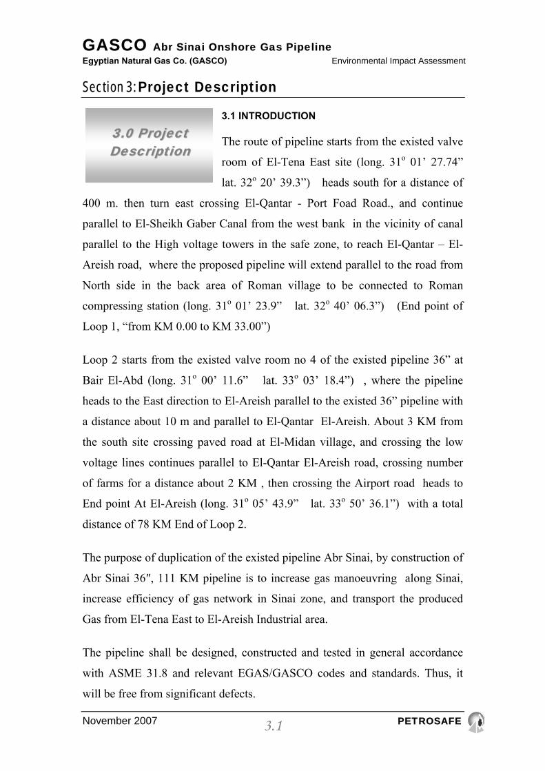
3.1 INTRODUCTION
The route of pipeline starts from the existed valve
room of El-Tena East site (long. 31o 01’ 27.74”
lat. 32o 20’ 39.3”) heads south for a distance of
400 m. then turn east crossing El-Qantar - Port Foad Road., and continue
parallel to El-Sheikh Gaber Canal from the west bank in the vicinity of canal
parallel to the High voltage towers in the safe zone, to reach El-Qantar – El-
Areish road, where the proposed pipeline will extend parallel to the road from
North side in the back area of Roman village to be connected to Roman
compressing station (long. 31o 01’ 23.9” lat. 32o 40’ 06.3”) (End point of
Loop 1, “from KM 0.00 to KM 33.00”)
Loop 2 starts from the existed valve room no 4 of the existed pipeline 36” at
Bair El-Abd (long. 31o 00’ 11.6” lat. 33o 03’ 18.4”) , where the pipeline
heads to the East direction to El-Areish parallel to the existed 36” pipeline with
a distance about 10 m and parallel to El-Qantar El-Areish. About 3 KM from
the south site crossing paved road at El-Midan village, and crossing the low
voltage lines continues parallel to El-Qantar El-Areish road, crossing number
of farms for a distance about 2 KM , then crossing the Airport road heads to
End point At El-Areish (long. 31o 05’ 43.9” lat. 33o 50’ 36.1”) with a total
distance of 78 KM End of Loop 2.
The purpose of duplication of the existed pipeline Abr Sinai, by construction of
Abr Sinai 36″, 111 KM pipeline is to increase gas manoeuvring along Sinai,
increase efficiency of gas network in Sinai zone, and transport the produced
Gas from El-Tena East to El-Areish Industrial area.
The pipeline shall be designed, constructed and tested in general accordance
with ASME 31.8 and relevant EGAS/GASCO codes and standards. Thus, it
will be free from significant defects.

GASCO Abr Sinai Onshore Gas Pipeline Egyptian Natural Gas Co. (GASCO) Environmental Impact Assessment
Section 3: Project Description
November 2007 PETROSAFE
3.2
Its continued fitness for purpose requires that it shall be operated in accordance
with ASME 31.8, EGAS/GASCO relevant codes and standards and specific
factors. One of the main factors is that it is protected against corrosion.
3.2. DESIGN
A pipeline which has been designed constructed and tested in general
accordance with ASME 31.8 and relevant EGAS/GASCO codes and standards
will be free from significant defects. Its continued fitness for purpose requires
that it shall be operated in accordance with ASME 31.8, EGAS/GASCO
relevant codes and standards and specific factors given in a) to e) inclusive.
a) The pipeline is protected against corrosion.
b) The pipeline is protected against external interference.
c) The pipeline is not adversely influenced by ground movement, from
natural or man made causes (e.g. geological faults and mining).
d) Modification, maintenance and repair of the pipeline is carried out in
such a way that its integrity is preserved.
e) The pipeline is not adversely affected by fatigue.
The factors a) to d) above inclusive, routine inspection and preventive
measures shall be implemented.
3.3. CODES AND STANDARDS
• API 5L For line pipes
• API 6D for valves
• ANSI B 16.9 and MSS SP 75 for fittings
• ANSI B 16.5 and MSS SP 44 for flanges
• ASME B 31.8 and EGAS/GASCO Local regulations for construction
and pipeline design.
GASCO Abr Sinai Onshore Gas Pipeline Egyptian Natural Gas Co. (GASCO) Environmental Impact Assessment
Section 3: Project Description
November 2007 PETROSAFE
3.3
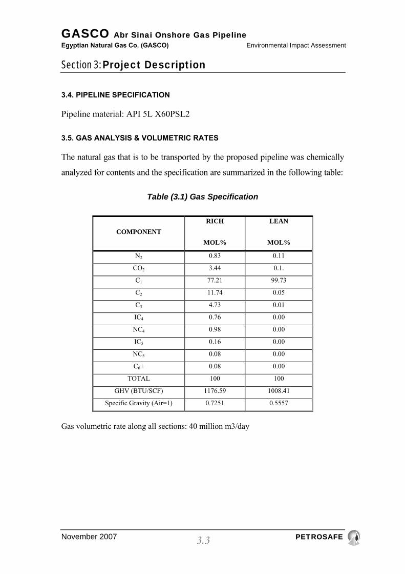
3.4. PIPELINE SPECIFICATION
Pipeline material: API 5L X60PSL2
3.5. GAS ANALYSIS & VOLUMETRIC RATES
The natural gas that is to be transported by the proposed pipeline was chemically
analyzed for contents and the specification are summarized in the following table:
Table (3.1) Gas Specification
COMPONENT RICH
MOL%
LEAN
MOL%
N2 0.83 0.11
CO2 3.44 0.1.
C1 77.21 99.73
C2 11.74 0.05
C3 4.73 0.01
IC4 0.76 0.00
NC4 0.98 0.00
IC5 0.16 0.00
NC5 0.08 0.00
C6+ 0.08 0.00
TOTAL 100 100
GHV (BTU/SCF) 1176.59 1008.41
Specific Gravity (Air=1) 0.7251 0.5557
Gas volumetric rate along all sections: 40 million m3/day
GASCO Abr Sinai Onshore Gas Pipeline Egyptian Natural Gas Co. (GASCO) Environmental Impact Assessment
Section 3: Project Description
November 2007 PETROSAFE
3.4
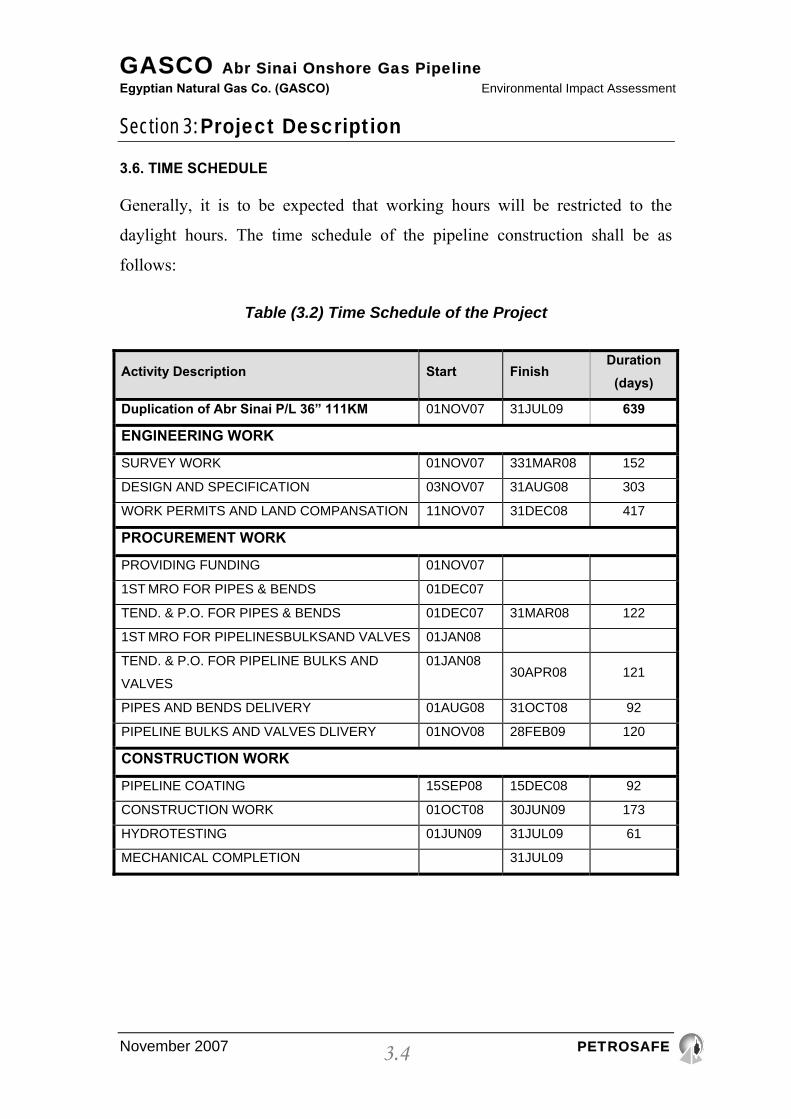
3.6. TIME SCHEDULE
Generally, it is to be expected that working hours will be restricted to the
daylight hours. The time schedule of the pipeline construction shall be as
follows:
Table (3.2) Time Schedule of the Project
Activity Description Start Finish Duration
(days)
Duplication of Abr Sinai P/L 36” 111KM 01NOV07 31JUL09 639
ENGINEERING WORK
SURVEY WORK 01NOV07 331MAR08 152
DESIGN AND SPECIFICATION 03NOV07 31AUG08 303
WORK PERMITS AND LAND COMPANSATION 11NOV07 31DEC08 417
PROCUREMENT WORK
PROVIDING FUNDING 01NOV07
1ST MRO FOR PIPES & BENDS 01DEC07
TEND. & P.O. FOR PIPES & BENDS 01DEC07 31MAR08 122
1ST MRO FOR PIPELINESBULKSAND VALVES 01JAN08
TEND. & P.O. FOR PIPELINE BULKS AND
VALVES
01JAN0830APR08 121
PIPES AND BENDS DELIVERY 01AUG08 31OCT08 92
PIPELINE BULKS AND VALVES DLIVERY 01NOV08 28FEB09 120
CONSTRUCTION WORK
PIPELINE COATING 15SEP08 15DEC08 92
CONSTRUCTION WORK 01OCT08 30JUN09 173
HYDROTESTING 01JUN09 31JUL09 61
MECHANICAL COMPLETION 31JUL09
GASCO Abr Sinai Onshore Gas Pipeline Egyptian Natural Gas Co. (GASCO) Environmental Impact Assessment
Section 3: Project Description
November 2007 PETROSAFE
3.5
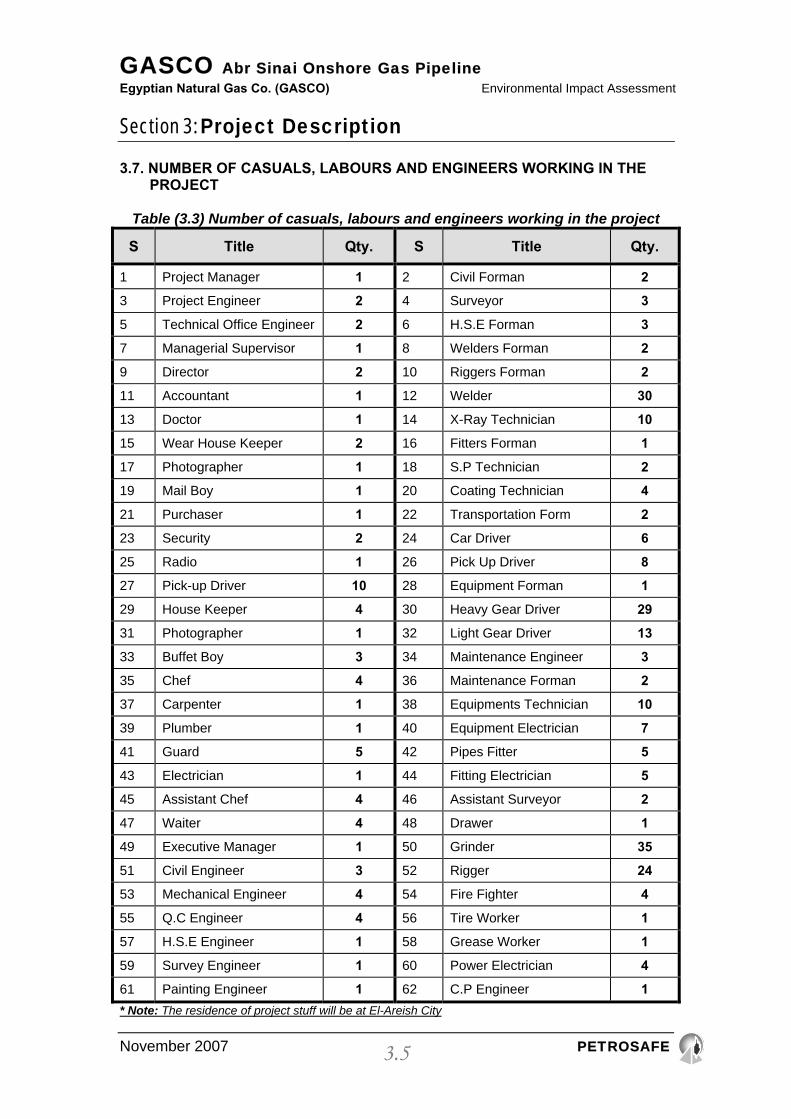
3.7. NUMBER OF CASUALS, LABOURS AND ENGINEERS WORKING IN THE PROJECT
Table (3.3) Number of casuals, labours and engineers working in the project
S Title Qty. S Title Qty.
1 Project Manager 1 2 Civil Forman 2
3 Project Engineer 2 4 Surveyor 3
5 Technical Office Engineer 2 6 H.S.E Forman 3
7 Managerial Supervisor 1 8 Welders Forman 2
9 Director 2 10 Riggers Forman 2
11 Accountant 1 12 Welder 30
13 Doctor 1 14 X-Ray Technician 10
15 Wear House Keeper 2 16 Fitters Forman 1
17 Photographer 1 18 S.P Technician 2
19 Mail Boy 1 20 Coating Technician 4
21 Purchaser 1 22 Transportation Form 2
23 Security 2 24 Car Driver 6
25 Radio 1 26 Pick Up Driver 8
27 Pick-up Driver 10 28 Equipment Forman 1
29 House Keeper 4 30 Heavy Gear Driver 29
31 Photographer 1 32 Light Gear Driver 13
33 Buffet Boy 3 34 Maintenance Engineer 3
35 Chef 4 36 Maintenance Forman 2
37 Carpenter 1 38 Equipments Technician 10
39 Plumber 1 40 Equipment Electrician 7
41 Guard 5 42 Pipes Fitter 5
43 Electrician 1 44 Fitting Electrician 5
45 Assistant Chef 4 46 Assistant Surveyor 2
47 Waiter 4 48 Drawer 1
49 Executive Manager 1 50 Grinder 35
51 Civil Engineer 3 52 Rigger 24
53 Mechanical Engineer 4 54 Fire Fighter 4
55 Q.C Engineer 4 56 Tire Worker 1
57 H.S.E Engineer 1 58 Grease Worker 1
59 Survey Engineer 1 60 Power Electrician 4
61 Painting Engineer 1 62 C.P Engineer 1 * Note: The residence of project stuff will be at El-Areish City

GASCO Abr Sinai Onshore Gas Pipeline Egyptian Natural Gas Co. (GASCO) Environmental Impact Assessment
Section 3: Project Description
November 2007 PETROSAFE
3.6
3.8. TYPES & NUMBER OF EQUIPMENTS USED DURING CONSTRUCTION
Table (3.4) Types & number of equipments used during the construction phase
S Equipment Qty.
1 Double Cabin Car 5
2 Double Cabin Car 4*4 8
3 Pick Up 4
4 Bus (26 Persons) 6
5 Puller 5
6 Generator 200-250 K.V 5
7 Crane 50 Ton. 3
8 Side Boom D8 13
9 Pipe Welder 4
10 Pipe Carrier 2
11 Welding Machine 37
12 Low Bed 3
13 Water Tank Car 5
14 Solar Tank Car 2
15 Agriculture Excavator 5
16 Truck 6
17 Excavator 6
18 Loader 4
19 Bulldozer D8 3
20 Trailer 4
21 Compressor 5
22 Sand Plaster 5
23 Cement Mixer 2
24 Boom Excavator 2
25 Ambulance 1
26 Compression Pump 2
27 Filling Pump 2

GASCO Abr Sinai Onshore Gas Pipeline Egyptian Natural Gas Co. (GASCO) Environmental Impact Assessment
Section 3: Project Description
November 2007 PETROSAFE
3.7
28 Handling Pump 2
29 Test Compressor 2
3.9. CONSTRUCTION
Construction will be carried out by qualified and approved contractors under
the supervisions and monitoring of GASCO/EGAS personals.
The work will broadly be split into the following phases:
• Right of Way.
• Pipe storage and stringing of pipe.
• Trenching.
• Welding and weld inspection.
• Wrapping of joints.
• Visual wrap inspection.
• Holiday Detection
• Air tests.
• Ditching.
• Installation of valves.
• Tie-ins including valve installations etc.
• Backfilling.
• Cleaning.
• Gauging Pig.
• Hydro test.
• Additional air test.
• Dewatering.
• Magnetic cleaning pig.
• Geometric pig.
• Drying & commissioning.

GASCO Abr Sinai Onshore Gas Pipeline Egyptian Natural Gas Co. (GASCO) Environmental Impact Assessment
Section 3: Project Description
November 2007 PETROSAFE
3.8
3.9.1. R.O.W.
The Company and Contractor will manage access to the construction areas
through permits. The Company is responsible for providing permits and
documents etc. for access to the Right of Way for the construction of the
pipeline and all crossings. Clearing the R.O.W. and preparing it for the
construction work shall be done by the Contractor at his own expense.
The Contractor shall ensure that they have written clearance form the
Company‘s Archaeologist indicating the location of any suspected
remains/relics before commencing excavation.
The Contractor shall avoid undue damage to crops, trees, roads and properties
on the Right of Way. The Contractor is responsible for all damages to crops,
buildings, installations and properties adjacent to the Right of Way which may
occur, however caused, due to the construction works. Any expenses for such
damages shall be borne by the Contractor.
Where any irrigation or drainage installations (Canals, ditches, etc.) are
encountered on the Right of Way the Contractor shall provide and install
temporary connections so as to avoid interruption of, or variation in the
required flow of water. This will be to the satisfaction of the authority in
control of the waterways. The Contractor shall as soon as possible construct or
reinstate to the original condition and the satisfaction of the Company, all
structures and installations connected with irrigation which have previously
been disturbed by the works.
The Contractor shall prepare the Right of Way in a manner allowing ditching,
stringing and laying of the pipeline correctly without injuring pipe coating, or
endangering human life.
GASCO Abr Sinai Onshore Gas Pipeline Egyptian Natural Gas Co. (GASCO) Environmental Impact Assessment
Section 3: Project Description
November 2007 PETROSAFE
3.9
The Contractor shall maintain the necessary day and night warning signs to
protect persons, automotive vehicles…etc. The Contractor shall provide night
watchmen at known crossing points of the pipeline and at all other areas where
items of value are stored.
3.9.2. MATERIALS AND EQUIPMENT STORAGE
The storage location of materials and equipment will be at KM 55 (almost half
distance).
3.9.3. TRENCHING AND EXCAVATION ACTIVITIES
The contractor shall excavate and maintain the trench in which the pipeline is
to be laid exactly along the marked route as established by the survey and not
less than the following dimensions with + 10% where required by works in
some areas:
Depth to the pipe top elevation below the ground level:
• lm for all types of land other than rocky area.
• 0.7m for rocky areas.
• Width of trench D+O.4m (where D is the outer diameter of pipe with
coating).
For Abr Sinai Pipeline 36” 111Km: expected 330.000 m3 of desert land sand.
The Contractor may only deviate from the marked line with the written
permission of the Company.
The ditch bottom shall be uniformly graded and free from coarse rocks or
gravel or any similar bodies which could injure the pipeline coating.

GASCO Abr Sinai Onshore Gas Pipeline Egyptian Natural Gas Co. (GASCO) Environmental Impact Assessment
Section 3: Project Description
November 2007 PETROSAFE
3.10
3.9.4. PIPELINE LAYING TECHNIQUE
Pipe is not laid in a stressed condition; lowering operation shall be undertaken
in such a manner to minimize induced stresses due to construction procedures,
due consideration shall be given to the timing of these operation with respect to
maximum and minimum ambient temperature and ASME B 31.8 the trench
shall be maintained in dry conditions during lowering and back filling
operation.
The following steps must be followed:
1) Three side booms shall be used for the lowering in operation.
2) Side booms shall work from the R.O.W side of the trench and to be
positioned 15m apart and 3m from the trench centre line.
3) The portion of pipe line between trench and the bank shall be supported
by side booms holding the line in a gentle 'S' curve.
4) The vertical and horizontal alignment of the pipe shall conform to the
contour of the trench and there shall be no undue sag, twist or bend.
5) The 1st side boom shall position its boom over the trench centreline with
the 2nd and 3rd side booms positioning their booms to suit.
6) The 1st side boom shall lower the line into the trench carefully, the 2nd
and 3rd side booms shall lower in sequence to maintain a smooth line 'S'
curve.
7) When the 1st side boom has completed lowering the pipeline, riggers
shall unhook the sling and the 1st side boom shall move 15m beyond the
3rd side boom and hook-up the sling to its new position.
8) The sequence (5, 6&7) shall be repeated with the 2nd and 3rd side booms
as the line is lowered and the side boom advance in sequence along the
pipeline.
GASCO Abr Sinai Onshore Gas Pipeline Egyptian Natural Gas Co. (GASCO) Environmental Impact Assessment
Section 3: Project Description
November 2007 PETROSAFE
3.11
9) The lowering-in Forman shall be the person with sole responsibility for
controlling the movement of the equipment.
3.9.5. DITCHING
The Contractor shall excavate and maintain the trench in which the pipeline is
to be laid exactly along the marked route as established by the survey and not
less than the following dimensions with + 10% where required by works in
some areas
Depth to the pipe top elevation below the general ground level
1 m for all types of land other than rocky area
0.7 m for rocky areas.
Width of trench
D + 0.4 m
Where D is the outer diameter of pipe with coating.
Angle of trench
Rocky area- vertically cut
Desert areas:
Compacted sand - 40° to vertical
Running sand - 70° to vertical
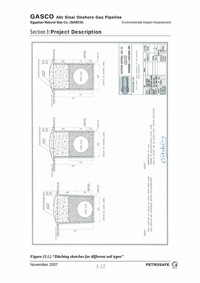
(see figure 3.1. shows ditching sketches for different soil types)
GASCO Abr Sinai Onshore Gas Pipeline Egyptian Natural Gas Co. (GASCO) Environmental Impact Assessment
Section 3: Project Description
November 2007 PETROSAFE
3.12
Figure (3.1.) “Ditching sketches for different soil types”
GASCO Abr Sinai Onshore Gas Pipeline Egyptian Natural Gas Co. (GASCO) Environmental Impact Assessment
Section 3: Project Description
November 2007 PETROSAFE
3.13
The ditch bottom shall be uniformly graded and free from coarse rocks or grave
or any similar bodies which could injure the pipeline coating.
At locations with irregular ground elevations (contours) additional excavation
may be necessary to eliminate undue bending of the pipe.
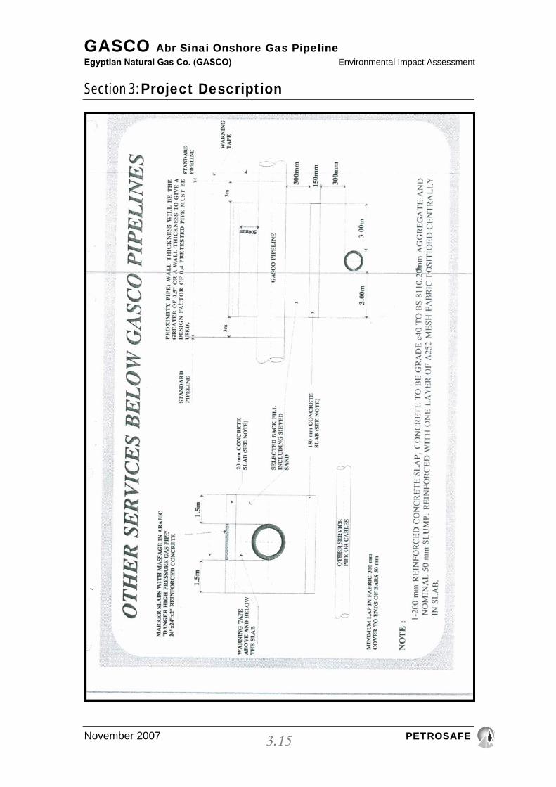
Where the route of the pipeline crosses with other underground utility lines, the
trench shall be deepened. The pipeline shall be installed below or above
existing lines or cables in accordance with drawings approved by the company.
(see figure 3.2. & 3.3.)
Procedures and minimum clearances are given in Local Regulation
L.R.l.6.5.C&S Proximity of GASCO Gas Business Pipelines to Other Services,
must be followed.
Where the route of the pipeline crosses roads, the requirements specified in
Local Regulations L.R 1.6 C&S – Road crossing, must be followed.

GASCO Abr Sinai Onshore Gas Pipeline Egyptian Natural Gas Co. (GASCO) Environmental Impact Assessment
Section 3: Project Description
November 2007 PETROSAFE
3.14
Figure (3.2.) “Crossing other services above GASCO Pipelines”
GASCO Abr Sinai Onshore Gas Pipeline Egyptian Natural Gas Co. (GASCO) Environmental Impact Assessment
Section 3: Project Description
November 2007 PETROSAFE
3.15
GASCO Abr Sinai Onshore Gas Pipeline Egyptian Natural Gas Co. (GASCO) Environmental Impact Assessment
Section 3: Project Description
November 2007 PETROSAFE
3.16
Figure (3.3.) “Crossing other services below GASCO Pipelines”
3.9.6. LOWERING AND BACKFILLING OF A PIPELINE
Lowering of pipeline shall only be carried out following a successful test of the
whole of the coating by the holiday detector and insuring that the testing is
100% passed (voltage according to the coating specifications) and free from
damage or any pinholes. The certification will be issued and signed by the
contractor to confirm a satisfactory test.
The bottom of the trench must be cleaned of any rocks, stones or hard objects.
The trench shall be padded with a minimum of 20 cm of sieved sand.
Wide non abrasive belts shall be used in all lowering operations and care shall
be taken when removing the belts from around the coated pipe. Any damage
caused to the pipe coating during the lowering operation shall be repaired
before lowering the pipe in the ditch.
No lowering operations shall be undertaken except in the presence of the
company or their representative. During this operation special care shall be
taken to ensure; that the pipe coating sustains no damage and that the pipe is
not laid in a stressed condition.
Lowering operations shall be under taken in such a manner to minimise
induced stresses due to construction procedures. Due consideration shall be
given to the
Company who must be satisfied that the pipe is evenly, bedded throughout its
length upon the bottom of the trench and is not riding upon stones or other
objects etc.
GASCO Abr Sinai Onshore Gas Pipeline Egyptian Natural Gas Co. (GASCO) Environmental Impact Assessment
Section 3: Project Description
November 2007 PETROSAFE
3.17
The trench shall be backfilled within 48 hours after lowering of pipe. Initial
backfill will be to a minimum height 20 cm. of sieved sand. The trench shall be
clear of any rocks stones or hard objects, the trench shall be padded with 20 cm
of sieved sand. Above and around the pipe a minimum of 20 cm sieved sand
backfill must be compacted around the pipe to provide protection from the
remainder of the backfill. The backfill will be thoroughly compacted by wet
tamping in 15 cm layers.
The backfill shall normally be crowned to a height of not less than 20 cm.
above the adjacent ground level.
Backfilling of trenches through roads shall be carried out immediately after the
pipe has been laid and with material as above. The backfill shall be compacted
in layers not exceeding 15 cm and finished level with the road surface. The
road surface shall be finally restored to the same condition as before work
started.
Backfilling of crossings must take place immediately after the pipe has been
laid and tested. The trench shall be clear of any rocks stones or hard objects,
the trench Shall be padded with a minimum of 20 cm of sieved sand.
Above and around the pipe a minimum of 20 cm sieved sand backfill must be
compacted around the pipe to provide protection from the remainder of the
backfill. The backfill will be thoroughly compacted by wet tamping in 15 cm
layers.
3.9.7. PIGGING METHODS
contractor shall clean, gauge, and repair the pipeline after construction
immediately. Clean water will be the test medium.

GASCO Abr Sinai Onshore Gas Pipeline Egyptian Natural Gas Co. (GASCO) Environmental Impact Assessment
Section 3: Project Description
November 2007 PETROSAFE
3.18
3.9.8. CLEANING FLUSHING AND GAUGING
• The pipeline shall be swabbed six times with air driven foam bodied pigs or
rubber cupped bi-directional pigs until it become clean of foreign material,
then cleaned with clean water at a flow rate determined by the company for
24 hours, at least, it shall then immediately be gauged with an air driven
gauge pig, fitted with an aluminium gauging plate having a diameter equal
to 95% of the internal diameter of the pipe for above 300mm and 90% for
300mm and below, temporary scraper station shall be supplied by
contractor for stage testing.
The discharge will be:
• A) small amount of dust from cleaning and will be disposed to industrial
dump.
• B) Water from flushing and will be disposed to industrial drain sewage.
3.9.9. HYDROSTATIC TESTING
• Water shall be clean fresh water and free from any substance which may be
harmful to pipe material.
• Fitter of sufficient capacity to accommodate the filling capacity of the
pumps shall be installed between the water source and the suction flange of
the pump and shall be kept in good order all the time of the operations
(mesh 20). Static pressure will be maintained by the lines for 24 hours with
no unexplainable drop in pressure for test to be acceptable.
• A pressure recording instrument shall be connected to the pipeline for the
duration of the test.
GASCO Abr Sinai Onshore Gas Pipeline Egyptian Natural Gas Co. (GASCO) Environmental Impact Assessment
Section 3: Project Description
November 2007 PETROSAFE
3.19
• Hydrostatic testing must be followed by dewatering and gauging, the
pipeline must not be left water in it.
• The pipeline will be tested in two sections; the water used in the first
section will be tested to show the possibility of using it in the second
section.
• Environmental friendly corrosion inhibitors chemicals will be used (please revert
to MSDS – appendix 6).
• The steps of the hydrostatic test are as following:
− A 'by direction' is placed in the beginning of the pipeline before
water flushing.
− The pipeline is filled with fresh clean water by use of pumps.
Filters are placed between the pumps and the pipeline to remove
any contaminants to enter to the pipeline.
− The by direction is moving in the entering water inside the pipeline
to guarantee the emptiness of the pipeline from air.
− The by direction comes out from the receiver trap.
− Assure that there are no 'air pockets' inside the valve rooms.
− The pressure is raised inside the pipeline till reaching 50% of the
required pressure for the test; for example: if the required pressure
is 105 bar, then the pressure is raised to 52.5 bar.
− The pressure is stopped for 12 hours. Patrolling on the pipeline and
the valve rooms to ensure the absence of any leakage.
− After 12 hours, the pressure is raised again till reaching to 105 bar.
GASCO Abr Sinai Onshore Gas Pipeline Egyptian Natural Gas Co. (GASCO) Environmental Impact Assessment
Section 3: Project Description
November 2007 PETROSAFE
3.20
− The pressure is for 24 hours observed and recorded on a chart
recorded.
− After checking and being sure that the pressure is stable for 24
hours, the pressure is lowered to 0 bars.
− The receiver trap is opened again and the 'by direction' is placed
for sweeping the water.
− The pipes are internally coated with anti-corrosion substances that don't
be affected by the pigging.
− The test duration is short; 24 hours, then the pipelines is emptied of the
water after.
The water that will be used in this test shall be taken on the two parts from El-
Salam canal for Loop#1 and from Mediterranean Sea in Al-Areish area for
Loop#2, and the generated effluent shall be gradually discharged to the same
source. The total estimated quantities of water are 92955 m3. About 27635 m3
of El-Salam canal water, and About 65320 m3 of sea water from
Mediterranean sea And the chemical anticorrosion that will be used in the
second loop are environmentally friendly, and there is no chemical or additives
will be used in the first Loop
Sampling and analysis for the wastewater before discharging shall be done
versus the limits passed in Laws 48/82 and 4/94. (refer to section #2 "Water
Pollution").
3.9.10. DEWATERING
• Dewatering will follow immediately upon completion of a satisfactory
hydrostatic test the pipeline must not be left with water in it.
• As a minimum this procedure will be based upon the use of foam bodied
pigs or rubber cupped bi-direction pigs.
GASCO Abr Sinai Onshore Gas Pipeline Egyptian Natural Gas Co. (GASCO) Environmental Impact Assessment
Section 3: Project Description
November 2007 PETROSAFE
3.21
• Pigs will be run until there is no evidence of water in the pipeline as
determined by the company.
• Test for water shall include assessment of the gain in weight of any foam
pig or measuring of the dew point of the compressed air into and out of the
pipe line.
• Measurement will take place before dewatering to complete arrangement
with the responsible authorities.
• Dewatering will continue until the company's engineer is satisfied that
pipeline is free from water within acceptance limit (∆ weight) is zero.
3.9.11. MAGNETIC CLEANING AND GEOMETRIC PIGGING
• A series of magnetic cleaning pigs will be run until the pipeline is judged by
the company to be free of magnetic debris.
• After the pipeline has been cleaned by the magnetic cleaning pig the
contractor will run a geometric pig. Acceptance of the pipeline will be
based upon a successful report by this pig.
• Following a successful run by the geometric pig the pipeline will be left
with positive pressure in it of at least 2 bar. The medium be with either dry
air or dry nitrogen as determined by the company.
The discharge will be some metallic components and will be disposed to
industrial dump.
3.9.12. DRYING AND COMMISSIONING
The pipeline will be dried by the application of either vacuum drying or by
flashing with dry nitrogen at ambient temperature to ensure that no operational
problems arise from water left in the pipeline
GASCO Abr Sinai Onshore Gas Pipeline Egyptian Natural Gas Co. (GASCO) Environmental Impact Assessment
Section 3: Project Description
November 2007 PETROSAFE
3.22
3.9.13. PIPELINE CROSSINGS 3.9.13.1. GENERAL
All pipeline crossings will be uncased unless otherwise specified by the
company. Impact protection measures (cast in site or pre-cast concrete slab)
shall be provided on all pipeline crossings. Warning tape shall be placed above
and below such impact protection. Above ground pipeline crossings shall not
be used in situation where alternative methods are possible. Horizontal
directional drilling (HDD) techniques will be used for sensitive crossings and
heavy traffic roads, open cut technique will be used for normal crossings.
Backfilling of crossings must take place immediately after the pipe has been
laid. The trench shall be clear of any rocks stones or hard objects, the trench
shall be padded with a minimum of 20 cm of sieved sand. Above and around
the pipe a minimum of 20 cm sieved sand backfill must be compacted around
the pipe to provide protection from the remainder of the backfill. The backfill
will be thoroughly compacted by wet tamping in 15 cm layers.
The wall thickness shall be greater of 0.5 inch or a wall thickness to give a
design factor of 0.4 with max. Wall thickness 0.75 inch providing that the
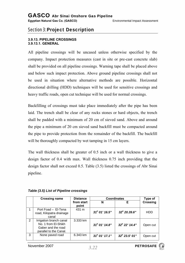
design factor shall not exceed 0.5. Table (3.5) listed the crossings of Abr Sinai
pipeline.
Table (3.5) List of Pipeline crossings
Crossing name Distance
from start point
Coordinates Type of Crossing N E
1 Port Foad – El-Tena road, Kilopatra drainage
canal
431 m 31o 01’ 16.5” 32o 20.39.6” HDD
2 Irrigation branch canal No. 1 from El-Shikh Gaber and the road parallel to the Canal.
3.333 km 31o 01’ 14.8” 32o 22’ 14.4” Open cut
3 None paved road 6.343 km
31o 01’ 17.1” 32o 23.5’ 01” Open cut

GASCO Abr Sinai Onshore Gas Pipeline Egyptian Natural Gas Co. (GASCO) Environmental Impact Assessment
Section 3: Project Description
November 2007 PETROSAFE
3.23
4 Irrigation branch canal No. 3 from El-Shikh
Gaber and the parallel road to the Canal.
8.13 km 31o 01’ 18.8” 32o 25’ 23.4” Open cut
5 Irrigation branch canal No. 5 from El-Shikh Gaber and the road parallel to the Canal.
13.36 km 31o 01’ 22.7” 32o 23’ 32.7” Open cut
6 Irrigation branch canal No. 7 from El-Shikh Gaber and the road parallel to the Canal.
17.803 km 31o 01’ 26.1” 32o 31’ 32.2” Open cut
7 El-Farama Port-Foad Paved road.
23 31o 01’ 27.9” 32o 33’ 07.6” HDD
8 Small Paved road 34 km 31o 00’ 11.5” 33o 07’ 30.4” Open cut
9 Small Paved road (interance to Mazar
village)
53 km 31o 05’ 25.9” 33o 45’ 05.2” Open cut
10 El-Midan Village Paved road
64 km 31o 04’ 0.6” 33o 34’ 53” HDD
11 El-Areish- Airport Paved road
79 km 31o 05’ 40.7” 33o 50’ 11.3” HDD
Specific requirements for the various types of crossings are detailed below.
3.9.13.2. CASED CROSSINGS
Cased crossings shall not be used in situations where alternative methods are
available. (Used in crossing which will be done by boring, … etc.)
All cased crossings will be carried out by thrust bore.
The coated pipeline shall be laid in either concrete or steel casings. This will be
thrust bored in accordance with API and ASME standards plus any attached
specification drawings. The casing should be extended 3 meter (min) from the
end of crossing at both sides.
The inside of the casing should be cleaned before the pipe is pulled or pushed
into place. Immediately after the pipe is in place where applicable casing and
seals shall be installed.
GASCO Abr Sinai Onshore Gas Pipeline Egyptian Natural Gas Co. (GASCO) Environmental Impact Assessment
Section 3: Project Description
November 2007 PETROSAFE
3.24
Where the casing is steel the complete cased crossing shall have an electrical
resistance between pipe and casing of more than 100 ohms before being tied in.
if a lower resistance is measured, the pipe shall be removed from the casing,
the insulation repaired and the pipe re-installed.
For a distance of 8 meters from each end of the casing the pipe shall have firm
bearing on the bottom of the trench to prevent the pipe from settling. This may
be accomplished by either compacting the bottom of the trench or by placing
earth filled bags under the pipe at 1 meter intervals.
The distance between insulators shall be submitted by the contractor for
approval by the company. This shall be in advance. They will be 0.5m from
each end of the casing and then 1.5m apart.
The wall thickness shall be the greater of 0.5 inch or a wall thickness to give a
design factor of 0.4 with max. Wall thickness 0.75 inch providing that the
design factor shall not exceed 0.5.
3.9.13.3. UNDERGROUND CROSSINGS
The pipes shall be laid 1.5 meter below the lowest bed of the water course or
road crossing.
The wall thickness for a coated pipeline for underground crossings should be
the greater of 0.5 inch or a wall thickness to give a design factor of 0.4 with
max. Wall thickness 0.75 inch providing that the design factor shall not exceed
0.5.
The pipe shall be laid with concrete slabs. The concrete slabs should be laid
above the pipeline by distance of 50 cm, at least, to protect the pipeline from
third party activities and to minimize the life loads on the pipeline.

GASCO Abr Sinai Onshore Gas Pipeline Egyptian Natural Gas Co. (GASCO) Environmental Impact Assessment
Section 3: Project Description
November 2007 PETROSAFE
3.25
The concrete slabs should be laid in contact with each other to be as one unit in
distributing the load.
Backfilling for the crossing should be with well compacted sieved sand.
Concrete slabs should be prefabricated (precast) before lowering the slab in
position.
For railway crossing GASCO prefer using horizontal directional drilling with
the same condition in item 2.3.2 and the depth not less than 4m at any point
under railway.
3.9.13.4. DRAINAGE AND CANAL CROSSINGS
Crossings may be constructed by open-cut, boring, directional drilling or
tunnelling methods. Where open cut method is used the pipeline should be laid
at a cover allowing for future bed movement and dredging operations or
similar. Temporary flume pipes or other methods should be considered to
ensure that there is no disruption of weight coating if required such as
reinforced concrete to maintain negative buoyancy of the pipe both during
construction and in service. Attention to be given to the integrity of flood or
tidal barriers during construction and care to be taken to prevent pollution of
water courses.
In all cases the minimum pipe wall thickness shall be 0.5 ins, or using a design
factor of 0.4, which ever is greater.
Where a pipeline crosses water courses such as a ditch or stream, the pipeline
should be located at such depth as will provide a minimum cover of 1 meter
from the true cleaned bottom of the ditch or stream to the top pf the concrete
pad or 2 meter of the adjoining field level.
GASCO Abr Sinai Onshore Gas Pipeline Egyptian Natural Gas Co. (GASCO) Environmental Impact Assessment
Section 3: Project Description
November 2007 PETROSAFE
3.26
3.9.13.5. NAVIGATIONAL CANAL CROSSINGS
Major submerged crossings shall be treated as follows:
• The wall thickness for pipe used for canal crossings shall be the greater of
0.5 inch or a wall thickness to give a design factor of 0.4 with max. Wall
thickness 0.75 inch providing that the design factor shall not exceed 0.5.
• The pipes shall be laid 2.5 – 3 meters below the lowest bed of the water
course and according to the irrigation authority approved.
• The trench shall be of sufficient width to lay the line of the crossings as
shown on the drawing and shall be graded to ensure maximum support of
the pipeline, immediately after laying the pipeline.
• The navigational canal crossing shall be crossed with concrete coated pipe.
• No cold bends shall be accepted under water.
• The Contractor shall submit to the Company for approval, the details of the
method he intends to use in the crossing construction, the equipment to be
used, calculations of maximum bending stresses, calculations of the loads,
timing of operations and any information the company may require.
• GASCO prefer using horizontal directional drilling (HDD) with the same
condition in 1st item and the depth not less than 4m at any point under
water stream.

GASCO Abr Sinai Onshore Gas Pipeline Egyptian Natural Gas Co. (GASCO) Environmental Impact Assessment
Section 3: Project Description
November 2007 PETROSAFE
3.27
3.9.14. CORROSION CONTROL
The buried metallic structures (pipelines, valves) are coated and cathodically
protected according to BS, 739, part 1 as all gas networks.
3.9.15. REINSTATEMENT OF THE RIGHT OF WAY AND SITE
As soon as the pipe is laid and backfilled, the Contractor shall reinstate and
clean up the right-o-way.
All creeks, water courses, wells, siphons, drains, streams, ditches and irrigation
channels shall be reinstated to their former condition and if necessary their
banks shall be pitched with stone and/or faced with gabions to prevent washing
out or erosion.
The stripped top soil shall be replaced carefully in position after the completion
of the pipe laying operation.
All walls, fences, tracks, roads etc. shall be reinstated to their original
condition.
Excess excavated material to be removed and disposed of in line with local
regulations. Reinstatement shall be carried out within one week of backfilling
of the section backfilled.
3.9.16. RUPTURE PROTECTION TECHNIQUE
Protection of pipelines at crossings is wholly dependent on the type of crossing.
The following guidelines shall be applied:

GASCO Abr Sinai Onshore Gas Pipeline Egyptian Natural Gas Co. (GASCO) Environmental Impact Assessment
Section 3: Project Description
November 2007 PETROSAFE
3.28
3.9.16.1. GENERAL
With the exception of crossings done by Boring machines (railway, highway,
etc.), all pipeline crossings with open cut shall be unsleeved. Impact protection
measures such as cast in-situ or pre-cast concrete slabs shall be provided on all
pipeline crossings as a minimum requirement.
3.9.16.2. UNDERGROUND
Backfilling of crossings must take place immediately after the pipe has been
laid. The trench must be clear of any rocks, stones or other hard objects which
could damage the external polyethylene coating. The trench shall be padded
with a minimum of 20 cm of sieved sand also above and around the pipe a
minimum of 20 cm of sieved sand backfill must be compacted to provide
protection from the remaining backfill.
The back fill will be compacted by wet tamping in 15 cm layers. The pipe shall
be laid and concrete slabs placed above the pipeline by a distance of 50 cm
(minimum). Concrete slabs should be laid in concrete with each other to
distribute external loads of backfill.
3.9.16.3. DRAINAGE AND SMALL CANALS < 4M WIDTH
No concrete or slabs required.
3.9.16.4. DRAINAGE AND CANALS > 4M WIDTH
Concrete slabs shall be used
3.9.16.5. NAVIGATION CANALS AND RIVERS CROSSINGS
Reinforced concrete coated pipe shall be used.
GASCO Abr Sinai Onshore Gas Pipeline Egyptian Natural Gas Co. (GASCO) Environmental Impact Assessment
Section 3: Project Description
November 2007 PETROSAFE
3.29
3.9.16.6. RAIL SLEEVE
Externally coated H.S. (High Strength) carbon steel sleeve pipe shall be used
for protection
3.9.17. NUMBER OF LINES AT EACH CROSSING
Unless specifically called for to lay one or more other pipelines to reduce
overall construction costs, all crossings shall be of a single pipeline only for the
specific duty.
3.9.18. COVER OF PIPELINE
Cover of pipelines will be dependent on the type of crossings, the following
guidelines shall be applied:
3.9.18.1. ROADS
Minimum cover to top of pipe shall be 1.5 meters
3.9.18.2. DRAINAGE AND SMALL CANALS < 4M WIDTH
Minimum cover of I meter from true cleaned bottom of ditch or stream.
3.9.18.3. DRAINAGE AND CANALS > 4M WIDTH
Minimum cover of 1.5 meters to top of pipe.
3.9.18.4. NAVIGATION CANALS AND RIVERS CROSSINGS
Concreted coated pipelines shall be laid 2.5 meters min. to 3 meters max.
below the lowest bed of the water course.
3.9.18.5. RAIL SLEEVE
Minimum cover of sleeve to be at 1.5 meters below rail level.
SUITABLE WARNING TAPS SHALL BE PLACED ON ALL PIPELINES.
GASCO Abr Sinai Onshore Gas Pipeline Egyptian Natural Gas Co. (GASCO) Environmental Impact Assessment
Section 3: Project Description
November 2007 PETROSAFE
3.30
3.9.19. WATER BODIES CROSSING METHODOLOGY
Crossing of Water bodies and main canals in this project shall not be done by
the traditional open-cut method. It shall be done using a new technology named
Horizontal Directional Drilling.
Horizontal Directional Drilling (HDD) is a trenchless methodology that
provides an installation alternative that can offer a number of benefits over
traditional open-cut. HDD can be implemented with very little disruption to
surface activities, requires less working space, and may be performed more
quickly than open-cut methods. Also, it can simplify or eliminate certain
permitting processes. This type of installation which was applied in municipal
underground infrastructure systems and petroleum products pipelines has seen
a dramatic increase in recent years. Although there are currently no national
standards regarding HDD installations for any pipe material, HDD pipeline
installations are becoming more and more common and may be the fastest
growing trenchless construction method today. They can be used to install new
pipelines or replace existing ones.
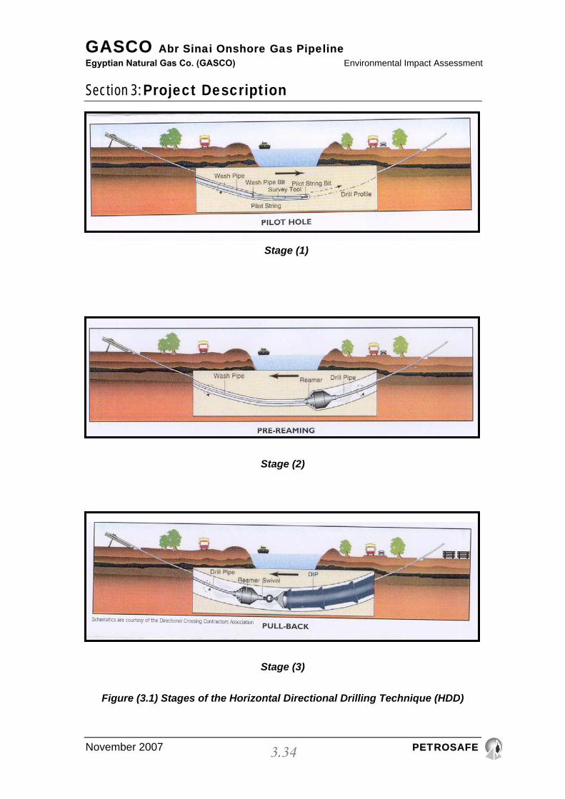
The technique stages are illustrated in Fig. (3.1), which shows the operation in
three stages, as follows:
Stage 1
The drilling rig and its associated equipment is set up and positioned on one
side of the crossing. The carriage framework is inclined to the desired entry
angle, which can be between 5° and 30°. Typically the entry angle is set
between 10° and 14° to the horizontal.
An 80mm dia. Pilot hole is drilled using either a mud motor or a jet bit,
attached to 73mm dia. Pilot drill pipe. The steering mechanism is provided by
GASCO Abr Sinai Onshore Gas Pipeline Egyptian Natural Gas Co. (GASCO) Environmental Impact Assessment
Section 3: Project Description
November 2007 PETROSAFE
3.31
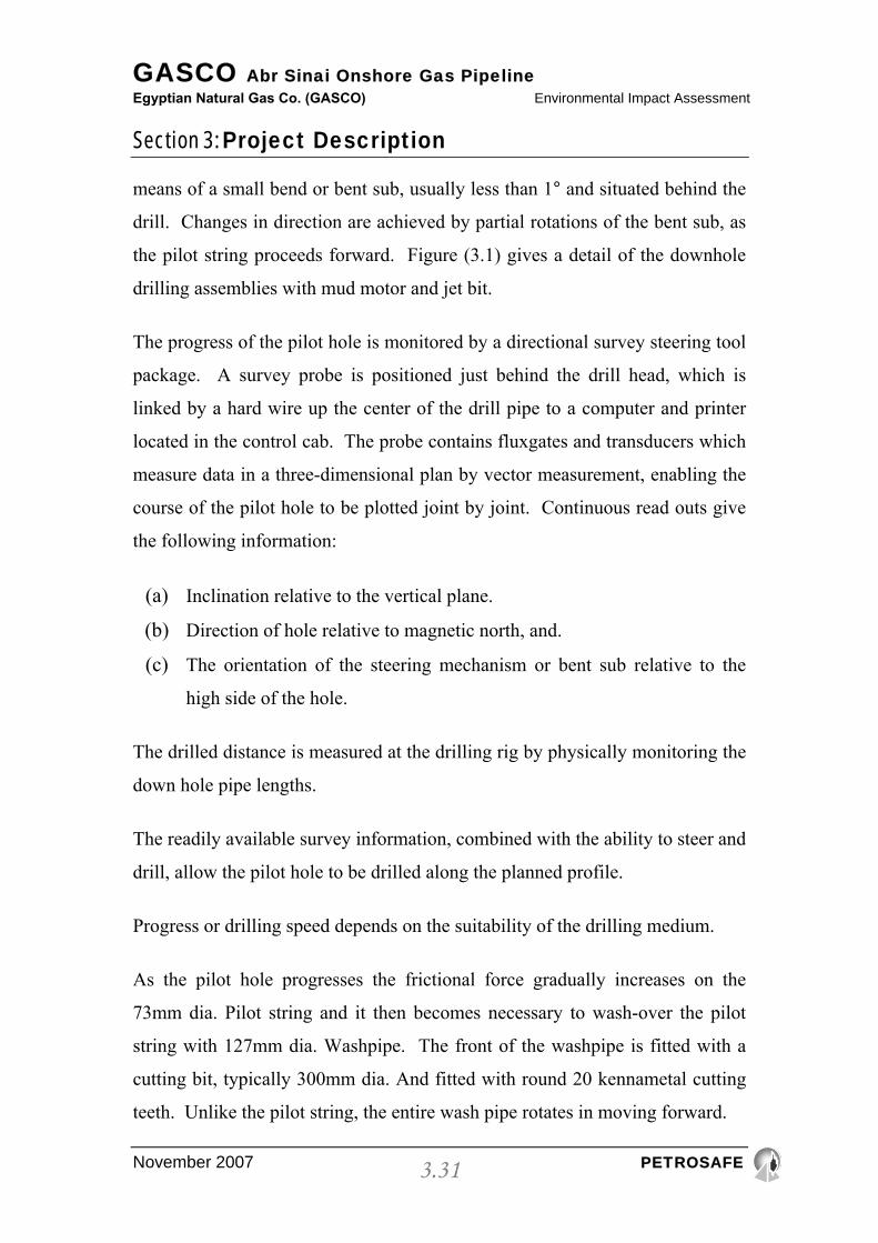
means of a small bend or bent sub, usually less than 1° and situated behind the
drill. Changes in direction are achieved by partial rotations of the bent sub, as
the pilot string proceeds forward. Figure (3.1) gives a detail of the downhole
drilling assemblies with mud motor and jet bit.
The progress of the pilot hole is monitored by a directional survey steering tool
package. A survey probe is positioned just behind the drill head, which is
linked by a hard wire up the center of the drill pipe to a computer and printer
located in the control cab. The probe contains fluxgates and transducers which
measure data in a three-dimensional plan by vector measurement, enabling the
course of the pilot hole to be plotted joint by joint. Continuous read outs give
the following information:
(a) Inclination relative to the vertical plane.
(b) Direction of hole relative to magnetic north, and.
(c) The orientation of the steering mechanism or bent sub relative to the
high side of the hole.
The drilled distance is measured at the drilling rig by physically monitoring the
down hole pipe lengths.
The readily available survey information, combined with the ability to steer and
drill, allow the pilot hole to be drilled along the planned profile.
Progress or drilling speed depends on the suitability of the drilling medium.
As the pilot hole progresses the frictional force gradually increases on the
73mm dia. Pilot string and it then becomes necessary to wash-over the pilot
string with 127mm dia. Washpipe. The front of the washpipe is fitted with a
cutting bit, typically 300mm dia. And fitted with round 20 kennametal cutting
teeth. Unlike the pilot string, the entire wash pipe rotates in moving forward.

GASCO Abr Sinai Onshore Gas Pipeline Egyptian Natural Gas Co. (GASCO) Environmental Impact Assessment
Section 3: Project Description
November 2007 PETROSAFE
3.32
In addition to reducing frictional forces the wash-over pipe increases the
diameter of the drilled hole. It also serves to smoothen the curve and to
eliminate any irregularities which may have occurred by use of the steering
mechanism.
Stage 2
Drilling progresses with alternate drilling of pilot drill pipe followed by wash-
pipe. The distance between the wash-over pipe cutting bit and the pilot drill bit
will be in the range of 25.0 m to 80.0 m. It is not advisable to have wash-over
pipe closer than 25.0 m as the proximity may adversely affect the accuracy of
the survey tool. Alternate drilling continues until both the pilot string and
wash-over pipe exit in the target area.
The pilot string is now removed from the system by pulling back to the drill
rig, leaving the wash pipe in places as a drawstring for the pre-ream operation.
For the pre-ream operation a barrel reamer, fitted with jets and cutting teeth, is
attached to the end of the wash pipe. The diameter of the pipe to be installed
dictates the diameter of the barred reamer. Typically the diameter of the
chosen reamer will be twice the diameter of the pipe to be installed. The barred
reamer is rotated along the drilled path enlarging the formed annulus.
As the reamer is pulled back, additional lengths of 127mm drill pipe are added
on behind, to ensure that a complete drill string remains in the hole for the next
operation.
Stage 3
Either before or during the drilling operation, the pipeline has been fabricated
on the target side of the crossing. On completion of hydrostatic testing, the
pipeline fabrication is raised onto conveyors. A pulling head is welded onto the
GASCO Abr Sinai Onshore Gas Pipeline Egyptian Natural Gas Co. (GASCO) Environmental Impact Assessment
Section 3: Project Description
November 2007 PETROSAFE
3.33
front end of the fabrication. The reamer is then transported to the target area,
i.e. the opposite side of the crossing. On completion of the pre-ream operation,
the reamer is disconnected. The assembly for the pipeline insertion consists of
the barrel reamer, followed by a universal joint, and a swivel to prevent
rotation of the pipeline being installed. The reamer and pull head assembly are
rotated and pulled back from the drill rig using the wash-over pipe.
Accordingly a further reaming of the hole takes place as the pipeline is being
inserted into the reamed hole.
GASCO Abr Sinai Onshore Gas Pipeline Egyptian Natural Gas Co. (GASCO) Environmental Impact Assessment
Section 3: Project Description
November 2007 PETROSAFE
3.34
Stage (2)
Stage (3)
Figure (3.1) Stages of the Horizontal Directional Drilling Technique (HDD)
Stage (1)

GASCO Abr Sinai Onshore Gas Pipeline Egyptian Natural Gas Co. (GASCO) Environmental Impact Assessment
Section 3: Project Description
November 2007 PETROSAFE
3.35
3.9.20. METHODS OF PIPE TESTING 3.9.20.1. WELDING AND WELD INSPECTION
a) Welders qualification test.
b) Non destructive tests:
• Radiographic test (R.T. 100%)
• Ultrasonic test (U.T. 10%)
• Diepenetrant test for weldlet, sweepolet and nippolet (½", 1")
c) Destructive tests (Mechanical Test), includes:
• Tensile test
• Bending test
• Macro etching test
• Impact test
• Nick break test
• Hardness test
Every 200 weld joint we made this test (0.5% of all welds) in the laboratory of
the faculty of engineering.
3.9.20.2. COATING
a) Pealing test (for weld joints coating). b) Holiday detector test (for all pipe line coating).
3.9.20.3. PAINTING (VALVE ROOMS)
For measuring the quality and thickness of the layers of painting.
All the waste disposal of above mentioned tests will be handled with
subcontractors certified for the job.

GASCO Abr Sinai Onshore Gas Pipeline Egyptian Natural Gas Co. (GASCO) Environmental Impact Assessment
Section 3: Project Description
November 2007 PETROSAFE
3.36
3.9.21. IMPACT PROTECTION
In normal circumstances, impact protection measures shall only be provided on
pipeline crossings as required in the above mentioned Local Regulations, and
the protection measures shall be undertaken as described in these Local
Regulations.
The pipeline route would have been checked in accordance with criteria for
population density proximity distances to buildings, roads, location classes .etc,
as defined in Local Regulation L.R. 1.2. C&S - Design & Construction of
Pipelines Proximity Criteria
Where it is not possible to meet this criteria, shall impact protection be
designed to meet the requirement of Local Regulation L.R. 1.6.5. C&S.
3.9.22. SPECIFICATIONS FOR CATHODIC PROTECTION 3.9.22.1. DESIGN
After consideration of the options in proprietary designs available the type
currently use by GASCO is generally satisfactory so this type shall continue to
be used, but modifications to prevent loss of cover plates is recommended.
3.9.22.2. CABLING
Standardized cabling arrangements shall be used throughout the pipeline
network.
3.9.22.3. LOCATION AND SPACING
Test points shall be located at spacing not generally exceeding 2 Km to both
provide sufficient test points for routine monitoring and also to facilitate the
carrying out of close interval potential surveys.
Test points shall be specified at:

GASCO Abr Sinai Onshore Gas Pipeline Egyptian Natural Gas Co. (GASCO) Environmental Impact Assessment
Section 3: Project Description
November 2007 PETROSAFE
3.37
a) Insulation Joints.
b) Sleeves.
c) Major crossings (e.g. roads, railways, canals and rivers).
d) Interference points (e.g. D.C. traction)
All tests facilities shall be accessible
3.9.22.4 REFERENCE NUMBERS
Each test point shall be given a unique reference number as per the cathodic
protection schedule for the pipeline section.

GASCO Abr Sinai Onshore Gas Pipeline Egyptian Natural Gas Co. (GASCO) Environmental Impact Assessment
Section 3: Project Description
November 2007 PETROSAFE
3.38
3.10. OPERATION
It is important that GASCO should take all reasonable precautions to safeguard
its pipeline and people living in the vicinity of its pipelines.
This code has been written to cover two specific areas of Pipeline Surveillance.
1) Pipeline Patrolling
2) Leakage Survey
3.10.1. PIPELINE PATROLLING
Pipeline Patrolling is carried out in order to identify activities or actions that
could damage the pipeline. It also identifies areas of concern such as land
slippage etc. in the general area of the pipeline that could cause subsequent
problems. The frequency of the patrol will vary for differing areas. In desert
regions there is minimal work carried out around the pipeline. In Urban areas
where there is a lot of excavation activity on water mains, sewers, etc. and the
frequency of inspection needs to be highest.
3.10.2. LEAKAGE SURVEY
Leakage Survey is carried out to protect the population and staff against the
effects of escaping gas and detect damage to the pipeline. It is therefore carried
out where the pipeline runs close to buildings and where staff work.
This Code is supported by Two Report Sheets one for each day of the survey
for Patrolling Duties and one for Leakage Survey duties. These two sheets are
designed to be the only documentation the operative needs to carry in the
performance of the task.
The locations for both the Pipeline Patrolling and frequency and leakage survey
must be determined in advance by a Responsible Engineer and reviewed at
least annually.
GASCO Abr Sinai Onshore Gas Pipeline Egyptian Natural Gas Co. (GASCO) Environmental Impact Assessment
Section 3: Project Description
November 2007 PETROSAFE
3.39
All pipeline routes should be classified fully according to ASME 31.8 within 6
months of implementation of this code by a Responsible Engineer. This should
also include those areas where regular leakage surveys will be carried out.
It is essential to take all reasonable precautions to reduce the risk of pipelines
being struck or damaged. The inspection and surveillance, applied to a
particular section of a pipeline, should reflect the likelihood of such damage at
that location and the type of frequency levels should be regularly reviewed at
intervals not exceeding two years.
All staff undertaking the Patrol duties and the leakage surveys must be fully
trained before carrying out these duties.
Where the two surveys coincide in terms of frequency they can be combined
into a Patrol and Leakage survey.
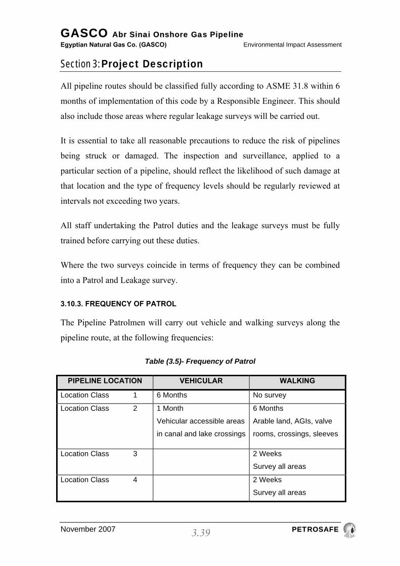
3.10.3. FREQUENCY OF PATROL
The Pipeline Patrolmen will carry out vehicle and walking surveys along the
pipeline route, at the following frequencies:
Table (3.5)- Frequency of Patrol
PIPELINE LOCATION VEHICULAR WALKING
Location Class 1 6 Months No survey
Location Class 2 1 Month
Vehicular accessible areas
in canal and lake crossings
6 Months
Arable land, AGIs, valve
rooms, crossings, sleeves
Location Class 3 2 Weeks
Survey all areas
Location Class 4 2 Weeks
Survey all areas
GASCO Abr Sinai Onshore Gas Pipeline Egyptian Natural Gas Co. (GASCO) Environmental Impact Assessment
Section 3: Project Description
November 2007 PETROSAFE
3.40
The Patrol will observe and report findings to the Sector Office on a daily basis
and where the safety of the pipeline is at risk, notification will be as soon as
possible.
The Patrol will be issued with written authorization to instruct other people,
affecting the safety of GASCO property, to stop their work or actions
immediately.
The Patrolman will need to complete a written Daily Report. These will be
logged again on a daily basis, in the Area Office. These Daily Reports will be
audited on a random basis by the Patrol's Supervisor.
The Survey Diary, issued to each Patrolman, will be completed by the end of
each day. The Survey Diary will contain all observations along the pipeline
route for a particular day. This Diary will be used as a check by the Patrol
Supervisor.
All necessary Permits or permission will be obtained from landowners,
farmers, railways, etc. prior to starting work. The Patrol will ensure that he
holds a valid Identity Card or Letter of Authorization.
In addition to watching and reporting on the GASCO pipelines, the Patrol will
establish a good liaison with farmers and landowners along the pipeline route.
It is not the intent to specifically test for the presence of leakage with gas
detection equipment during this survey.
3.10.4. RECORDS & OPERATING MANUALS
The constructing contractor will be responsible for the production of all kinds
of records relating to the whole construction job. These records include but not
limited to:

GASCO Abr Sinai Onshore Gas Pipeline Egyptian Natural Gas Co. (GASCO) Environmental Impact Assessment
Section 3: Project Description
November 2007 PETROSAFE
3.41
(One) Materials records that contain identification number, inspection
certificates, test certificates, etc.
(Two) Welding records (e.g. welder qualifications, welding procedure, etc.).
(Three) Protective coating records that contain date, method of cleaning,
material used, repairs, etc.
(Four) Painting records (e.g. paint type, grade of paint, paint batch
number,etc.)
(Five) Mechanical installation records (e.g. testing procedure, insulation
procedure, pipe alignment, etc.)
(Six) Structural steel work records (e.g. line, level, plumbness,
tightness of bolts, etc.)
In addition, Contractor shall supply all necessary maintenances manuals and
training in their application.
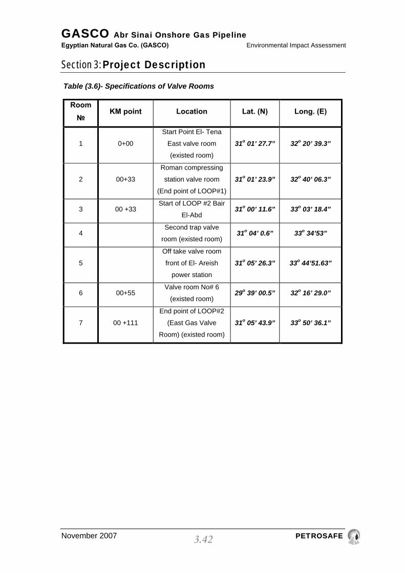
3.10.4. VALVE ROOMS
The following table illustrates the valve rooms proposed to be constructed and
their specifications.
GASCO Abr Sinai Onshore Gas Pipeline Egyptian Natural Gas Co. (GASCO) Environmental Impact Assessment
Section 3: Project Description
November 2007 PETROSAFE
3.42
Table (3.6)- Specifications of Valve Rooms
Room №
KM point Location Lat. (N) Long. (E)
1 0+00
Start Point El- Tena
East valve room
(existed room)
31o 01’ 27.7” 32o 20’ 39.3”
2 00+33
Roman compressing
station valve room
(End point of LOOP#1)
31o 01’ 23.9” 32o 40’ 06.3”
3 00 +33 Start of LOOP #2 Bair
El-Abd 31o 00’ 11.6” 33o 03’ 18.4”
4 Second trap valve
room (existed room) 31o 04’ 0.6” 33o 34’53”
5
Off take valve room
front of El- Areish
power station
31o 05’ 26.3” 33o 44’51.63”
6 00+55 Valve room No# 6
(existed room) 29o 39’ 00.5” 32o 16’ 29.0”
7 00 +111
End point of LOOP#2
(East Gas Valve
Room) (existed room)
31o 05’ 43.9” 33o 50’ 36.1”