
200/210/240 HP Jet Drive Installation Manual - … · 200/210/240 HP Jet Drive Installation Manual...
44
Page 1 90-10218040 DECEMBER 2003 200/210/240 HP Jet Drive Installation Manual NOTICE to COMMISSIONING DEALER Pre-delivery Preparation Instructions Must Be Performed Before Delivering Boat to the Product Owner. NOTICE to INSTALLER After Completing Installation, These Instructions Should Be Placed with the Product for the Owner’s Future Use. NOTICE to INSTALLER The United States Coast Guard does not have a method to determine the maximum recommended horse- power for Inboard Jet Boats. Therefore, it is the responsibility of the boat manufacturer to install the Mercury Jet Drive, as well as any other Jet Drive model, in a boat which has been determined to be of suitable size, weight, construction, and hull configuration for the power chosen. The Mercury Jet Drive, in particular, brings a new level of performance to the jet boat category and is capable of propelling many hulls at speeds exceed- ing 50 miles per hour. In selecting the proper Jet Drive package for a particular application, please consider the overall performance capability of the craft. Your boat may react to and handle differently with each Jet Drive model. PLEASE carefully test and evaluate the overall handling characteristics of the boat package before distribution for sale. If you have application or installation questions, please contact your Mercury Marine OEM Sales Coordinator. The Sales Coordinator will arrange to provide the necessary assistance. Please assess your boat’s performance completely before making the Jet Drive model selection. Safe boat- ing is good for everyone. Table of Contents General Information 2 . . . . . . . . . . . . . . . . . . . . . . . . . . Notice to Installer 2 . . . . . . . . . . . . . . . . . . . . . . . . . . Torque Specifications 3 . . . . . . . . . . . . . . . . . . . . . . Installation Requirements 3 . . . . . . . . . . . . . . . . . . . . . Battery/Battery Cables 3 . . . . . . . . . . . . . . . . . . . . . Boat Construction 4 . . . . . . . . . . . . . . . . . . . . . . . . . Engine Compartment Ventilation 4 . . . . . . . . . . . . Exhaust System 4 . . . . . . . . . . . . . . . . . . . . . . . . . . . Fuel Delivery System 5 . . . . . . . . . . . . . . . . . . . . . . Instrumentation 6 . . . . . . . . . . . . . . . . . . . . . . . . . . . Wiring Diagrams 7 . . . . . . . . . . . . . . . . . . . . . . . . . . Quicksilver Instrumentation, Typical Analog Installation Shown 7 . . . . . . . . . . . Typical System Layouts – Single Engine Product Configurations SmartCraft Speedometer and Tachometer 8 . . . . SmartCraft System Monitor – Model Year 2001 and Newer 8 . . . . . . . . . . . . . . . . Remote Control and Cables 9 . . . . . . . . . . . . . . . . Mercury Jet Drive Hull Dimensions 10 . . . . . . . . . . . . Steering Helm and Cable 11 . . . . . . . . . . . . . . . . . . Installing Jet Pump 12 . . . . . . . . . . . . . . . . . . . . . . . . . . Hull Cutout 12 . . . . . . . . . . . . . . . . . . . . . . . . . . . . . . Steering Cable Adjustment 16 . . . . . . . . . . . . . . . . Shift Cable Adjustment 19 . . . . . . . . . . . . . . . . . . . . Bilge Siphon Feature 22 . . . . . . . . . . . . . . . . . . . . . . . . Installing Bilge Siphon 22 . . . . . . . . . . . . . . . . . . . . Water By-Pass System 23 . . . . . . . . . . . . . . . . . . . . . . . Installation of Flushing Kit 25 . . . . . . . . . . . . . . . . . Operation Instructions 26 . . . . . . . . . . . . . . . . . . . . . Suggested Flushing Intervals 27 . . . . . . . . . . . . . . Installing Powerhead 28 . . . . . . . . . . . . . . . . . . . . . . . . Battery Cables and Remote Harness Connections 30 . . . . . . . . . . . . . . . . . . . . . . . . . . . . . Throttle Cable 33 . . . . . . . . . . . . . . . . . . . . . . . . . . . . . . Installation 33 . . . . . . . . . . . . . . . . . . . . . . . . . . . . . . . Oil Injection Set-Up 34 . . . . . . . . . . . . . . . . . . . . . . . . . . Trim Plate Adjustment 38 . . . . . . . . . . . . . . . . . . . . . . . Exhaust System Installation 39 . . . . . . . . . . . . . . . . . . General Exhaust System Notes 39 . . . . . . . . . . . . Exhaust Outlet Measurement Procedure 39 . . . . Top View 40 . . . . . . . . . . . . . . . . . . . . . . . . . . . . . . . . Aft View 41 . . . . . . . . . . . . . . . . . . . . . . . . . . . . . . . . . Side View 42 . . . . . . . . . . . . . . . . . . . . . . . . . . . . . . . Side View of Expansion Chamber Outlet Pipe and Exhaust Pipe Connection 43 . . . . . . . . . Pre-delivery Inspection 44 . . . . . . . . . . . . . . . . . . . . . . .
Transcript of 200/210/240 HP Jet Drive Installation Manual - … · 200/210/240 HP Jet Drive Installation Manual...

Page 190-10218040 DECEMBER 2003
200/210/240 HP Jet Drive Installation ManualNOTICE to COMMISSIONING DEALER
Pre-delivery Preparation Instructions Must Be Performed Before Delivering Boat to the Product Owner.
NOTICE to INSTALLER
After Completing Installation, These Instructions Should Be Placed with the Product for the Owner’s FutureUse.
NOTICE to INSTALLER
The United States Coast Guard does not have a method to determine the maximum recommended horse-power for Inboard Jet Boats. Therefore, it is the responsibility of the boat manufacturer to install the MercuryJet Drive, as well as any other Jet Drive model, in a boat which has been determined to be of suitable size,weight, construction, and hull configuration for the power chosen. The Mercury Jet Drive, in particular, bringsa new level of performance to the jet boat category and is capable of propelling many hulls at speeds exceed-ing 50 miles per hour.
In selecting the proper Jet Drive package for a particular application, please consider the overall performancecapability of the craft. Your boat may react to and handle differently with each Jet Drive model.
PLEASE carefully test and evaluate the overall handling characteristics of the boat package beforedistribution for sale.If you have application or installation questions, please contact your Mercury Marine OEM Sales Coordinator.The Sales Coordinator will arrange to provide the necessary assistance.
Please assess your boat’s performance completely before making the Jet Drive model selection. Safe boat-ing is good for everyone.
Table of ContentsGeneral Information 2. . . . . . . . . . . . . . . . . . . . . . . . . .
Notice to Installer 2. . . . . . . . . . . . . . . . . . . . . . . . . . Torque Specifications 3. . . . . . . . . . . . . . . . . . . . . .
Installation Requirements 3. . . . . . . . . . . . . . . . . . . . . Battery/Battery Cables 3. . . . . . . . . . . . . . . . . . . . . Boat Construction 4. . . . . . . . . . . . . . . . . . . . . . . . . Engine Compartment Ventilation 4. . . . . . . . . . . . Exhaust System 4. . . . . . . . . . . . . . . . . . . . . . . . . . . Fuel Delivery System 5. . . . . . . . . . . . . . . . . . . . . . Instrumentation 6. . . . . . . . . . . . . . . . . . . . . . . . . . . Wiring Diagrams 7. . . . . . . . . . . . . . . . . . . . . . . . . . Quicksilver Instrumentation,Typical Analog Installation Shown 7. . . . . . . . . . . Typical System Layouts –Single Engine Product ConfigurationsSmartCraft Speedometer and Tachometer 8. . . . SmartCraft System Monitor –Model Year 2001 and Newer 8. . . . . . . . . . . . . . . . Remote Control and Cables 9. . . . . . . . . . . . . . . .
Mercury Jet Drive Hull Dimensions 10. . . . . . . . . . . . Steering Helm and Cable 11. . . . . . . . . . . . . . . . . .
Installing Jet Pump 12. . . . . . . . . . . . . . . . . . . . . . . . . . Hull Cutout 12. . . . . . . . . . . . . . . . . . . . . . . . . . . . . . Steering Cable Adjustment 16. . . . . . . . . . . . . . . . Shift Cable Adjustment 19. . . . . . . . . . . . . . . . . . . .
Bilge Siphon Feature 22. . . . . . . . . . . . . . . . . . . . . . . . Installing Bilge Siphon 22. . . . . . . . . . . . . . . . . . . .
Water By-Pass System 23. . . . . . . . . . . . . . . . . . . . . . . Installation of Flushing Kit 25. . . . . . . . . . . . . . . . . Operation Instructions 26. . . . . . . . . . . . . . . . . . . . . Suggested Flushing Intervals 27. . . . . . . . . . . . . .
Installing Powerhead 28. . . . . . . . . . . . . . . . . . . . . . . . Battery Cables and Remote HarnessConnections 30. . . . . . . . . . . . . . . . . . . . . . . . . . . . .
Throttle Cable 33. . . . . . . . . . . . . . . . . . . . . . . . . . . . . . Installation 33. . . . . . . . . . . . . . . . . . . . . . . . . . . . . . .
Oil Injection Set-Up 34. . . . . . . . . . . . . . . . . . . . . . . . . . Trim Plate Adjustment 38. . . . . . . . . . . . . . . . . . . . . . . Exhaust System Installation 39. . . . . . . . . . . . . . . . . .
General Exhaust System Notes 39. . . . . . . . . . . . Exhaust Outlet Measurement Procedure 39. . . . Top View 40. . . . . . . . . . . . . . . . . . . . . . . . . . . . . . . . Aft View 41. . . . . . . . . . . . . . . . . . . . . . . . . . . . . . . . . Side View 42. . . . . . . . . . . . . . . . . . . . . . . . . . . . . . . Side View of Expansion Chamber OutletPipe and Exhaust Pipe Connection 43. . . . . . . . .
Pre-delivery Inspection 44. . . . . . . . . . . . . . . . . . . . . . .

200/210/240 HP JET DRIVE INSTALLATION MANUAL
Page 2 90-10218040 DECEMBER 2003
General Information
Notice to InstallerThroughout this publication, Warnings and Cautions (accompanied by the InternationalHazard Symbol) are used to alert the installer to special instructions concerning a particularservice or operation that may be hazardous if performed incorrectly or carelessly. ––Observe Them Carefully!
These “Safety Alerts,” alone, cannot eliminate the hazards that they signal. Strict com-pliance to these special instructions when performing the service, plus common sense oper-ation, are major accident prevention measures.
WARNINGHazards or unsafe practices which COULD result in severe personal injury or death.
CAUTIONHazards or unsafe practices which could result in minor personal injury or productor property damage.
IMPORTANT: Indicates information or instructions that are necessary for proper in-stallation and/or operation.
This installation manual has been written and published by the service department of Mer-cury Marine to aid installers when installing the products described herein.
It is assumed that these personnel are familiar with the installation procedures of these prod-ucts, or like or similar products manufactured and marketed by Mercury Marine. Also, thatthey have been trained in the recommended installation procedures of these products whichincludes the use of mechanics’ common hand tools and the special Mercury Marine or rec-ommended tools from other suppliers.
We could not possibly know of and advise the marine trade of all conceivable proceduresby which an installation might be performed and of the possible hazards and/or results ofeach method. We have not undertaken any such wide evaluation. Therefore, anyone whouses an installation procedure and/or tool, which is not recommended by the manufacturer,first must completely satisfy himself that neither his nor the product’s safety will be endan-gered by the installation procedure selected.
All information, illustrations, and specifications contained in this manual are based on thelatest product information available at time of publication. As required, revisions to this man-ual will be sent to all OEM boat companies.

200/210/240 HP JET DRIVE INSTALLATION MANUAL
Page 390-10218040 DECEMBER 2003
Torque SpecificationsNOTE: Tighten all fasteners, not listed, securely.
10 mm Fasteners(Powerhead to Pump) 47 Nm (35 lb ft)
Reverse Stop Screw 14 Nm (120 lb in.)
Forward Stop Screw 14 Nm (120 lb in.)
Ride Plate-to-Pump Screws 8.5 Nm (75 lb in.)
Pump Cover toPump Housing Nuts 47 Nm (35 lb ft)
Installation Requirements
IMPORTANT: The M 2 Jet Drive is considered an INBOARD engine. The boat it isinstalled in must m eet industry standards (ABYC, NMMA, etc.), federal standards andCoast Guard regulations for INBOARD engine installations
Battery/Battery CablesIMPORTANT: Boating industry standards (ABYC, N MMA, etc.), federal standards andCoast Guard regulations must be adhered to when installing battery. Be sure batterycable installation meets the pull test requirements and that positive battery terminalis properly insulated in accordance with regulations.
IMPORTANT: Engine electrical system is negative (–) ground. It is recommended (re-quired in some states) that battery be installed in an enclosed case. Refer to regula-tions for your area.
1. Select a battery that meets all of the following specifications:
FOR OPTIMAX ENGINES –
a. 12-volt marine type.
b. 1000 Marine Cranking Amps (MCA) or 750 Cold Cranking Amps (CCA) minimum.
c. Reserve capacity rating of at least 105 minutes.
FOR Carbureted and EFI ENGINES –
d. 12-volt marine type.
e. 670 Marine Cranking Amps (MCA) or520 Cold Cranking Amps (CCA) minimum.
f. Reserve capacity rating of at least 100 minutes.
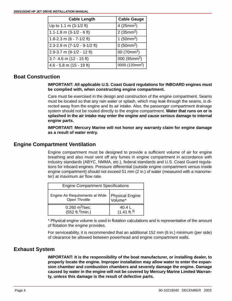
2. Select proper size positive (+) and negative (–) battery cables using chart. Batteryshould be located as close to engine as possible.
IMPORTANT: Terminals must be soldered to cable ends to ensure good electricalcontact. Use electrical grade (resin flux) solder only. Do not use acid flux solder, asit may cause corrosion and a subsequent failure.
200/210/240 HP JET DRIVE INSTALLATION MANUAL
Page 4 90-10218040 DECEMBER 2003
Cable Length Cable Gauge
Up to 1.1 m (3-1/2 ft) 4 (25mm2)
1.1-1.8 m (3-1/2 - 6 ft) 2 (35mm2)
1.8-2.3 m (6 - 7-1/2 ft) 1 (50mm2)
2.3-2.9 m (7-1/2 - 9-1/2 ft) 0 (50mm2)
2.9-3.7 m (9-1/2 - 12 ft) 00 (70mm2)
3.7- 4.6 m (12 - 15 ft) 000 (95mm2)
4.6 - 5.8 m (15 - 19 ft) 0000 (120mm2)
Boat ConstructionIMPORTANT: All applicable U.S. Coast Guard regulations for INBOARD engines mustbe complied with, when constructing engine compartment.
Care must be exercised in the design and construction of the engine compartment. Seamsmust be located so that any rain water or splash, which may leak through the seams, is di-rected away from the engine and its air intake. Also, the passenger compartment drainagesystem should not be routed directly to the engine compartment. Water that runs on or issplashed in the air intake may enter the engine and cause serious damage to internalengine parts.
IMPORTANT: Mercury Marine will not honor any warranty claim for engine damageas a result of water entry.
Engine Compartment VentilationEngine compartment must be designed to provide a sufficient volume of air for enginebreathing and also must vent off any fumes in engine compartment in accordance withindustry standards (ABYC, NMMA, etc.), federal standards and U.S. Coast Guard regula-tions for inboard engines. Pressure differential (outside engine compartment versus insideengine compartment) should not exceed 51 mm (2 in.) of water (measured with a manome-ter) at maximum air flow rate.
Engine Compartment Specifications
Engine Air Requirements at WideOpen Throttle
Physical EngineVolume*
0.260 m3/sec.(552 ft.3/min.)
40.4 L (1.41 ft.3)
* Physical engine volume is used in flotation calculations and is representative of the amountof flotation the engine provides.
For serviceability, it is recommended that an additional 152 mm (6 in.) minimum (per side)of clearance be allowed between powerhead and engine compartment walls.
Exhaust SystemIMPORTANT: It is the responsibility of the boat manufacturer, or installing dealer, toproperly locate the engine. Improper installation may allow water to enter the expan-sion chamber and combustion chambers and severely damage the engine. Damagecaused by water in the engine will not be covered by Mercury Marine Limited W arran-ty, unless this damage is the result of defective parts.

200/210/240 HP JET DRIVE INSTALLATION MANUAL
Page 590-10218040 DECEMBER 2003
The engine must be properly located to ensure that water will not enter the engine throughthe exhaust system. Determine the correct engine height by taking measurements (a) and(b), with boat at rest in the water and maximum load aboard. Subtract (b) from (a) to find(c). If (c) is less than specified in chart, boat construction must be altered to properly lowerwaterline relative to exhaust chamber.
b
ca
d
59216
a - From Waterline to Top of Transomb - From Highest Point on Expansion Chamber to Top of Transomc - (a) minus (b) = (c)d - Waterline at Rest (at Maximum Load)
Model c = (a) minus (b)
Jet Drive (c) must be 203 mm (8 in.) or more.
Fuel Delivery System
WARNINGBoating standards (NMMA, ABYC, etc.), federal standards and U. S. Coast Guardregulations for INBOARD engines must be adhered to when installing fuel deliverysystem. Failure to comply could result in severe personal injury or death.
CAUTIONRemove plastic plug from fuel inlet fitting. Attach fuel line to fuel fitting with U.S.Coast Guard approved hose clamp. Inspect for fuel leaks.
1. Fuel pickup should be at least 25 mm (1 in.) from the bottom of the fuel tank to preventpicking up impurities.
2. Fuel lines used must be U.S. Coast Guard approved (USCG type A1), fittings and linesmust not be smaller than 8 mm (5/16 in.) I.D.
3. On installations requiring long lines or numerous fittings, larger size lines should beused.
4. Fuel line should be installed free of stress and firmly secured to prevent vibration and/orchafing.
5. Sharp bends in fuel line should be avoided.
200/210/240 HP JET DRIVE INSTALLATION MANUAL
Page 6 90-10218040 DECEMBER 2003
6. A flexible fuel line must be used to connect fuel line to engine fuel pump to absorb deflec-tion when engine is running.
7. A primer bulb is not necessary with this application. If a primer bulb is used, it must beU.S. Coast Guard approved for inboard engine installations.
8. Vapor separator must be vented to fuel tank. Vent hose must comply with U.S. CoastGuard/ABYC regulations.
Instrumentation
CAUTIONIf a fused accessory panel is to be used, it is recommended that a separate circuit(properly fused) be used from the battery to the fuse panel with sufficient wire sizeto handle the intended current load.
NOTE: Check the charging capability of the engine. The electrical load of the boat shouldnot exceed this capacity.
We recommend the use of Mercury Precision or Quicksilver Instrumentation and WiringHarnesses. Refer to Mercury Precision Parts Accessories Guide for selection.
If other than Mercury Precision or Quicksilver electrical accessories are to be used, it is goodpractice to use waterproof ignition components (ignition switch, lanyard stop switch, etc.).A typical jet boat of this nature will see water splashed on these components. Therefore,precautions must be taken to avoid ignition failure due to shorting out of ignition compo-nents.
WARNINGSudden stopping of engine (shorting ignition components) while boat is underwaywill cause loss of steering control due to loss of thrust. This loss of steering controlmay cause property damage, personal injury or death.
A warning horn must be incorporated in the wiring harness (see wiring diagram) to alert theuser of an overheat, low oil condition or oil pump failure.
IMPORTANT: If a warning horn system is not installed by the boat manufacturer, Mer-cury Marine will not honor any warranty claims for engine damage as a result of over-heating or lack of engine oil.
Route instrumentation wiring harness back to engine, making sure that harness does notrub or get pinched. If an extension harness is required, be sure to secure connection proper-ly. Fasten harnesses to boat at least every 460 mm (18 in.), using appropriate fasteners.
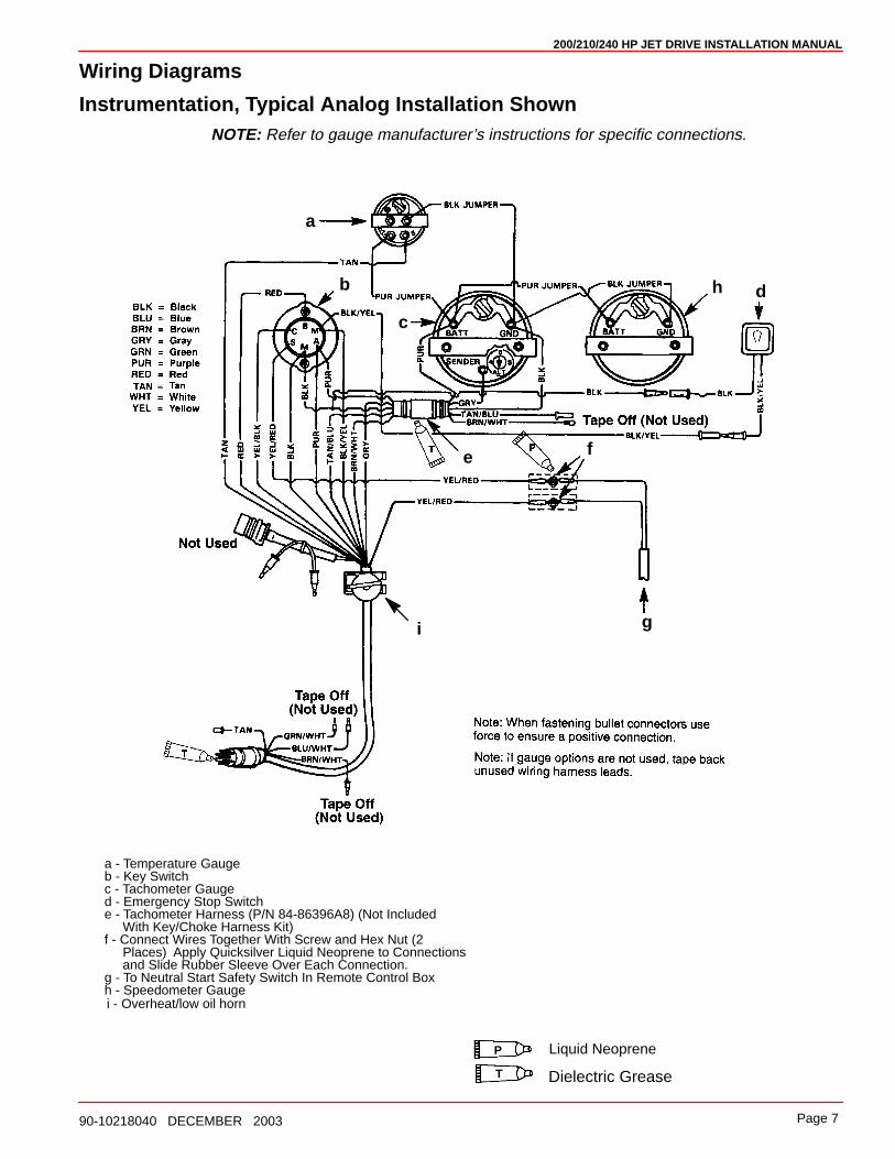
a - Temperature Gaugeb - Key Switchc - Tachometer Gauged - Emergency Stop Switche - Tachometer Harness (P/N 84-86396A8) (Not Included With Key/Choke Harness Kit)f - Connect Wires Together With Screw and Hex Nut (2 Places) Apply Quicksilver Liquid Neoprene to Connections and Slide Rubber Sleeve Over Each Connection.g - To Neutral Start Safety Switch In Remote Control Box
Liquid Neoprene
Dielectric GreaseT
h - Speedometer Gaugei - Overheat/low oil horn
a
b
c
d
e f
g
h
i
P
200/210/240 HP JET DRIVE INSTALLATION MANUAL
Page 790-10218040 DECEMBER 2003
Wiring Diagrams
Instrumentation, Typical Analog Installation ShownNOTE: Refer to gauge manufacturer’s instructions for specific connections.
200/210/240 HP JET DRIVE INSTALLATION MANUAL
Page 8 90-10218040 DECEMBER 2003
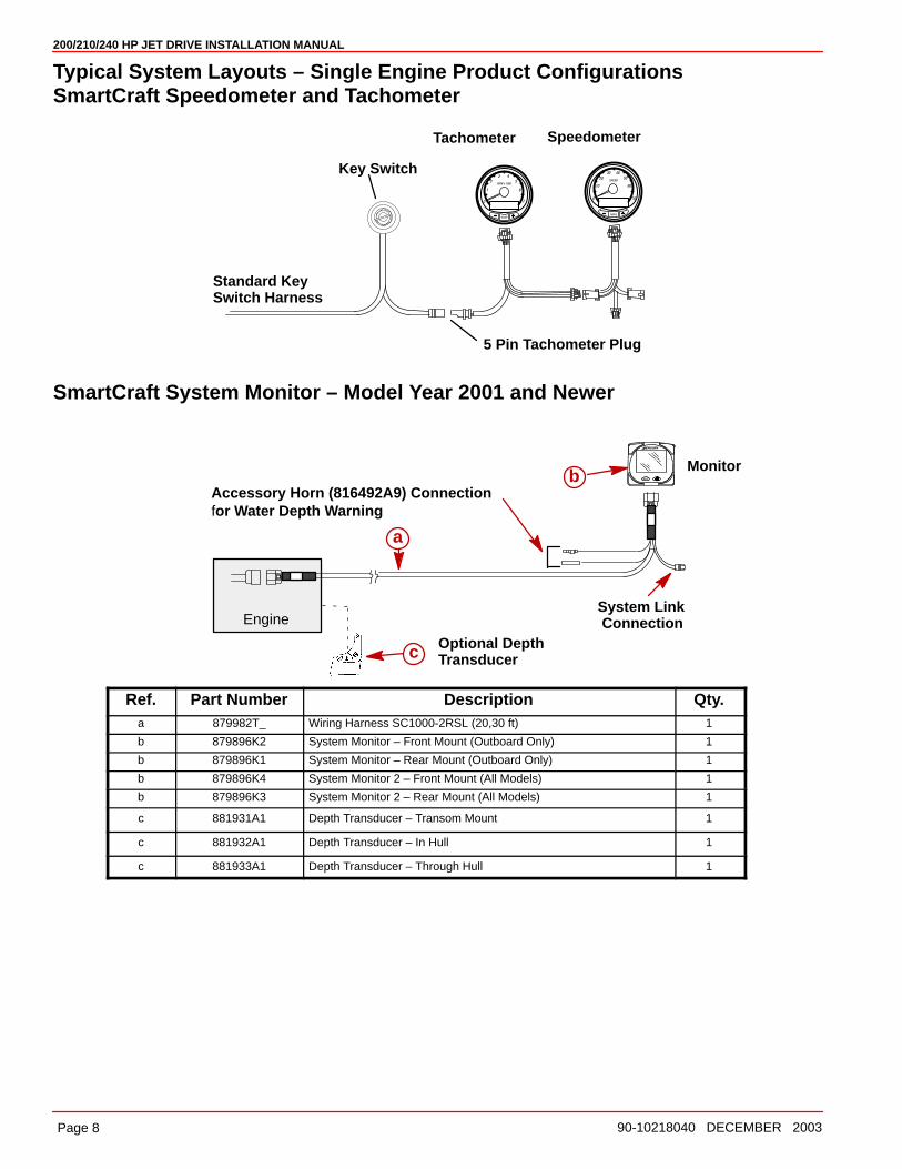
Typical System Layouts – Single Engine Product ConfigurationsSmartCraft Speedometer and Tachometer
Tachometer Speedometer
Standard Key Switch Harness
Key Switch
5 Pin Tachometer Plug
SmartCraft System Monitor – Model Year 2001 and Newer
Engine
Monitor
System Link Connection
a
bAccessory Horn (816492A9) Connectionfor Water Depth Warning
Optional DepthTransducerc
Ref. Part Number Description Qty.a 879982T_ Wiring Harness SC1000-2RSL (20,30 ft) 1
b 879896K2 System Monitor – Front Mount (Outboard Only) 1
b 879896K1 System Monitor – Rear Mount (Outboard Only) 1
b 879896K4 System Monitor 2 – Front Mount (All Models) 1
b 879896K3 System Monitor 2 – Rear Mount (All Models) 1
c 881931A1 Depth Transducer – Transom Mount 1
c 881932A1 Depth Transducer – In Hull 1
c 881933A1 Depth Transducer – Through Hull 1
200/210/240 HP JET DRIVE INSTALLATION MANUAL
Page 990-10218040 DECEMBER 2003
Remote Control and CablesThe remote control must provide the following required features:
• Start-in-gear protection
• Neutral RPM limit at 2,000 RPMNote: This applies to dual lever remote controls as well as single lever remote controls.
• High strength mechanism to accommodate loads transmitted to the remote control
• Shift cable travel of 76 mm �3 mm (3 inches �1/8 in.).
• Ability to use 40 series shift cable
The remote control must meet the above criteria as well as the design criteria outlined inthe ABYC manual pertaining to Mini-Jet Boats (Standard P-23).
SHIFT CABLE
The shift cable to be used MUST MEET the following criteria:
• 40-Series Cable
• 40 Series bulkhead fitting at output end
• Allow for a minimum of 76 mm (3 in.) of travel.
• A means of attaching and locking the cable to the shift cable bracket (provided).
• Cable end at pump must allow for a 1/4 inch clevis pin and cotter pin (all provided) toconnect cable to the reverse gate.
• Protected against water intrusion and/or corrosion as the cable end (at the pump) is sub-mersed in water with the boat at rest.
The shift cable end (at the pump) is submersed in water. It should be sealed against waterintrusion, protected against corrosion and be able to withstand the shift loads imparted onit by the reverse gate.
Follow shift cable adjustment procedure for proper adjustment.
THROTTLE CABLE
The throttle cable must have one end compatible with the control box. The other end musthave Mercury style connectors.
Follow throttle cable adjustment procedures for proper adjustment.
200/210/240 HP JET DRIVE INSTALLATION MANUAL
Page 10 90-10218040 DECEMBER 2003
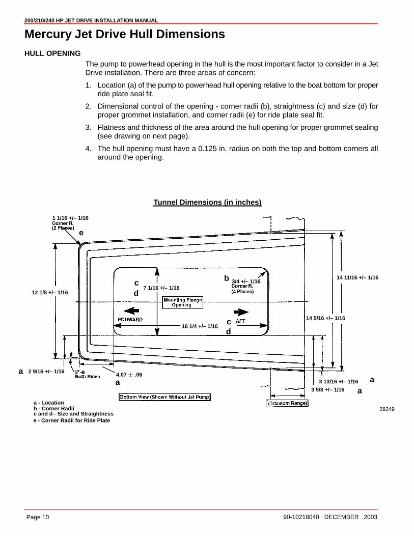
Mercury Jet Drive Hull DimensionsHULL OPENING
The pump to powerhead opening in the hull is the most important factor to consider in a JetDrive installation. There are three areas of concern:
1. Location (a) of the pump to powerhead hull opening relative to the boat bottom for properride plate seal fit.
2. Dimensional control of the opening - corner radii (b), straightness (c) and size (d) forproper grommet installation, and corner radii (e) for ride plate seal fit.
3. Flatness and thickness of the area around the hull opening for proper grommet sealing(see drawing on next page).
4. The hull opening must have a 0.125 in. radius on both the top and bottom corners allaround the opening.
1 1/16 +/– 1/16
3/4 +/– 1/167 1/16 +/– 1/16
16 1/4 +/– 1/16
14 11/16 +/– 1/16
14 5/16 +/– 1/16
2 9/16 +/– 1/16
12 1/8 +/– 1/16
3 13/16 +/– 1/16
3 5/8 +/– 1/16
b - Corner Radiic and d - Size and Straightness
a - Location
Tunnel Dimensions (in inches)
a
b
c
e
a
a
d
cd
28249
4.07 � .06
a
e - Corner Radii for Ride Plate

200/210/240 HP JET DRIVE INSTALLATION MANUAL
Page 1190-10218040 DECEMBER 2003
Steering Helm and CableSTEERING HELM
The steering helm must limit steering cable travel to 88.9 ± 2.5 mm (3-1/2 in. ± 1/8 in.).
WARNINGFailure to limit steering cable travel at the helm could pre-load the cable resultingin premature failure of a steering component causing loss of steering. This loss ofsteering could cause property damage, personal injury or death.
STEERING CABLE
The steering cable to be used MUST MEET the following criteria:
• 60 Series Steering Cable
• 60 Series bulkhead fitting at output end
• Allow for a minimum of 95.3 mm (3.75 in.) of travel.
• Cable end at pump must allow for a 5/16 in. threaded adaptor shouldered thru-bolt andlock nut to connect the cable to the steering arm.
• A means of attaching and locking the cable to the steering cable bracket (provided).
• Protected against water intrusion and/or corrosion as the cable end (at the pump) is sub-mersed in water with the boat at rest.
• The steering cable should be able to withstand the steering loads imparted on it by therudder.
A locking tab is provided by Mercury to be used with the steering cable having threads andlocknuts located 287 mm (11.31 in.) from cable end at pump with cable at center of travel.
Follow steering cable adjustment procedure for proper adjustment.
METHOD FOR CONTROLLING LOCATION AND SIZE
Mercury Marine recommends that the tunnel opening be done as a part of the manufactureof the tunnel. This will ensure consistency of location as well as size.
200/210/240 HP JET DRIVE INSTALLATION MANUAL
Page 12 90-10218040 DECEMBER 2003
Installing Jet Pump
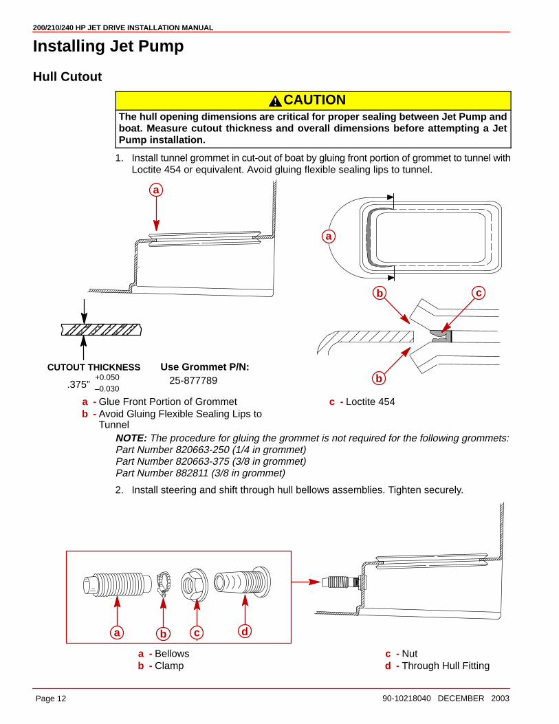
Hull Cutout
CAUTIONThe hull opening dimensions are critical for proper sealing between Jet Pump andboat. Measure cutout thickness and overall dimensions before attempting a JetPump installation.
1. Install tunnel grommet in cut-out of boat by gluing front portion of grommet to tunnel withLoctite 454 or equivalent. Avoid gluing flexible sealing lips to tunnel.
ÀÀÀÀÀÀÀÀÀÀÀÀÀ
CUTOUT THICKNESS
.375”+0.050
–0.030
Use Grommet P/N:25-877789
a
a
b
b
c
a - Glue Front Portion of Grommetb - Avoid Gluing Flexible Sealing Lips to
Tunnel
c - Loctite 454
NOTE: The procedure for gluing the grommet is not required for the following grommets:Part Number 820663-250 (1/4 in grommet)Part Number 820663-375 (3/8 in grommet)Part Number 882811 (3/8 in grommet)
2. Install steering and shift through hull bellows assemblies. Tighten securely.
a b c d
a - Bellowsb - Clamp
c - Nutd - Through Hull Fitting

200/210/240 HP JET DRIVE INSTALLATION MANUAL
Page 1390-10218040 DECEMBER 2003
3. Route steering cable through the through hull fitting and bellows. Route cable throughthe port side hole in flange of pump housing. Install nut on cable before routing cablethrough wear ring.
58142
a b
a - Shift Cableb - Wear Ring
4. Install tab washer and nut on cable after guiding through wear ring. Locate tab washerin tab hole. Coarse cable adjustment is made using these nuts. Do not tighten until afterfinal steering adjustment is made.
58143
dc
a
b
a - Tab Holeb - Nutc - Tab Washerd - 6.4 mm (0.25 in.)
200/210/240 HP JET DRIVE INSTALLATION MANUAL
Page 14 90-10218040 DECEMBER 2003
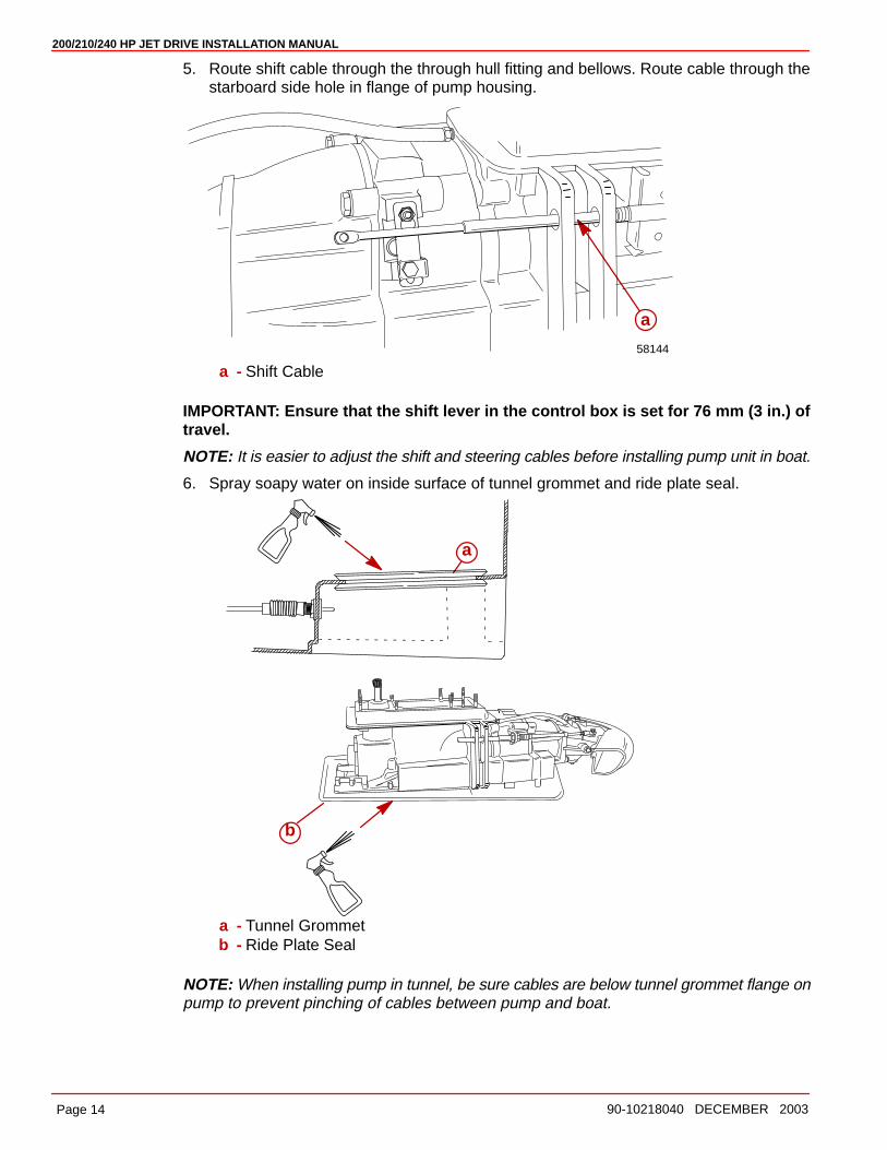
5. Route shift cable through the through hull fitting and bellows. Route cable through thestarboard side hole in flange of pump housing.
58144
a
a - Shift Cable
IMPORTANT: Ensure that the shift lever in the control box is set for 76 mm (3 in.) oftravel.
NOTE: It is easier to adjust the shift and steering cables before installing pump unit in boat.
6. Spray soapy water on inside surface of tunnel grommet and ride plate seal.
a
b
a - Tunnel Grommetb - Ride Plate Seal
NOTE: When installing pump in tunnel, be sure cables are below tunnel grommet flange onpump to prevent pinching of cables between pump and boat.
200/210/240 HP JET DRIVE INSTALLATION MANUAL
Page 1590-10218040 DECEMBER 2003
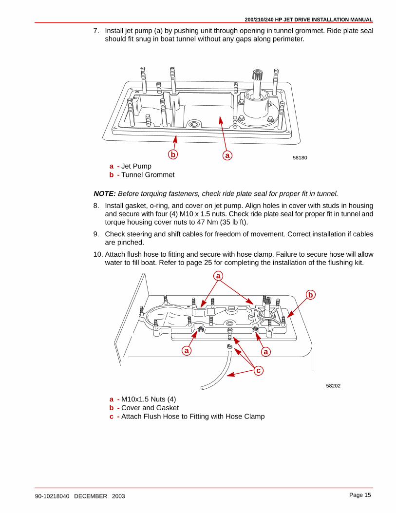
7. Install jet pump (a) by pushing unit through opening in tunnel grommet. Ride plate sealshould fit snug in boat tunnel without any gaps along perimeter.
58180aba - Jet Pumpb - Tunnel Grommet
NOTE: Before torquing fasteners, check ride plate seal for proper fit in tunnel.
8. Install gasket, o-ring, and cover on jet pump. Align holes in cover with studs in housingand secure with four (4) M10 x 1.5 nuts. Check ride plate seal for proper fit in tunnel andtorque housing cover nuts to 47 Nm (35 lb ft).
9. Check steering and shift cables for freedom of movement. Correct installation if cablesare pinched.
10. Attach flush hose to fitting and secure with hose clamp. Failure to secure hose will allowwater to fill boat. Refer to page 25 for completing the installation of the flushing kit.
a
a
b
58202
a
c
a - M10x1.5 Nuts (4)b - Cover and Gasketc - Attach Flush Hose to Fitting with Hose Clamp
200/210/240 HP JET DRIVE INSTALLATION MANUAL
Page 16 90-10218040 DECEMBER 2003
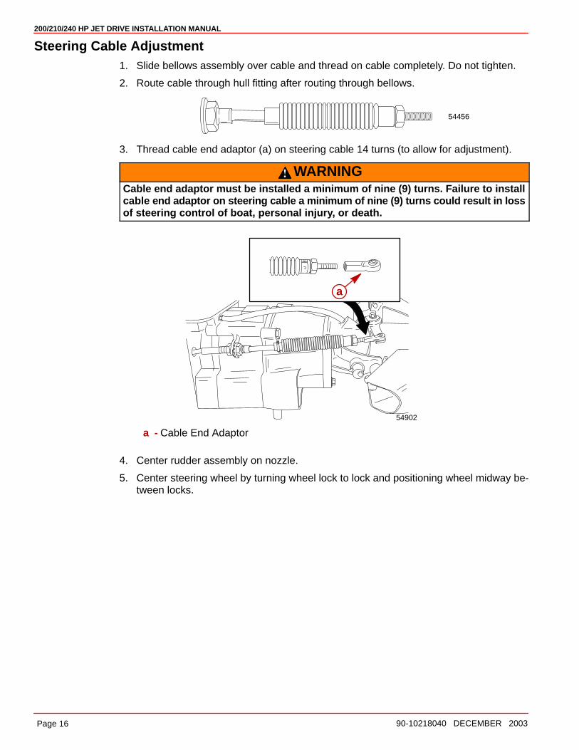
Steering Cable Adjustment1. Slide bellows assembly over cable and thread on cable completely. Do not tighten.
2. Route cable through hull fitting after routing through bellows.
54456
3. Thread cable end adaptor (a) on steering cable 14 turns (to allow for adjustment).
WARNINGCable end adaptor must be installed a minimum of nine (9) turns. Failure to installcable end adaptor on steering cable a minimum of nine (9) turns could result in lossof steering control of boat, personal injury, or death.
54902
a
a - Cable End Adaptor
4. Center rudder assembly on nozzle.
5. Center steering wheel by turning wheel lock to lock and positioning wheel midway be-tween locks.
200/210/240 HP JET DRIVE INSTALLATION MANUAL
Page 1790-10218040 DECEMBER 2003
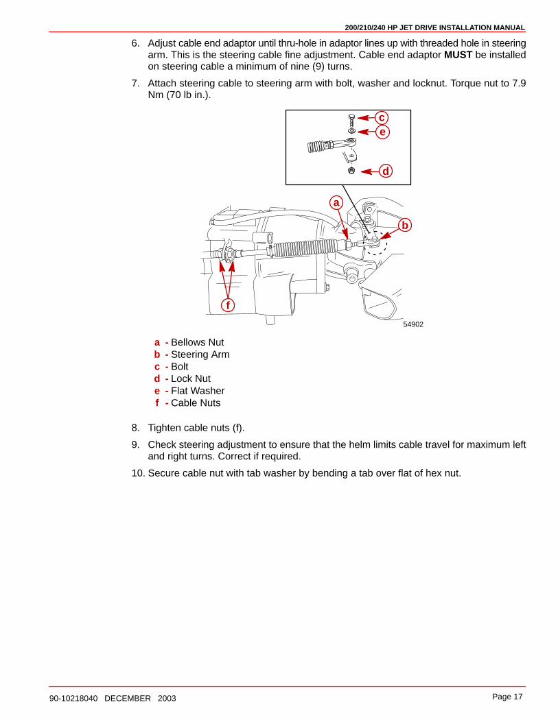
6. Adjust cable end adaptor until thru-hole in adaptor lines up with threaded hole in steeringarm. This is the steering cable fine adjustment. Cable end adaptor MUST be installedon steering cable a minimum of nine (9) turns.
7. Attach steering cable to steering arm with bolt, washer and locknut. Torque nut to 7.9Nm (70 lb in.).
54902
b
a
ce
d
f
a - Bellows Nutb - Steering Armc - Boltd - Lock Nute - Flat Washerf - Cable Nuts
8. Tighten cable nuts (f).
9. Check steering adjustment to ensure that the helm limits cable travel for maximum leftand right turns. Correct if required.
10. Secure cable nut with tab washer by bending a tab over flat of hex nut.
200/210/240 HP JET DRIVE INSTALLATION MANUAL
Page 18 90-10218040 DECEMBER 2003
11. Apply perfect seal to end threads and cable conduit end.
19
Perfect Seal19
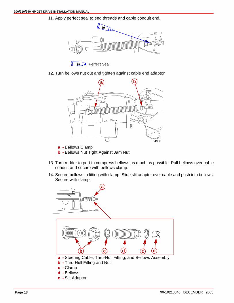
12. Turn bellows nut out and tighten against cable end adaptor.
54908
a b
a - Bellows Clampb - Bellows Nut Tight Against Jam Nut
13. Turn rudder to port to compress bellows as much as possible. Pull bellows over cableconduit and secure with bellows clamp.
14. Secure bellows to fitting with clamp. Slide slit adaptor over cable and push into bellows.Secure with clamp.
a
b c cd ea - Steering Cable, Thru-Hull Fitting, and Bellows Assemblyb - Thru-Hull Fitting and Nutc - Clampd - Bellowse - Slit Adaptor
200/210/240 HP JET DRIVE INSTALLATION MANUAL
Page 1990-10218040 DECEMBER 2003
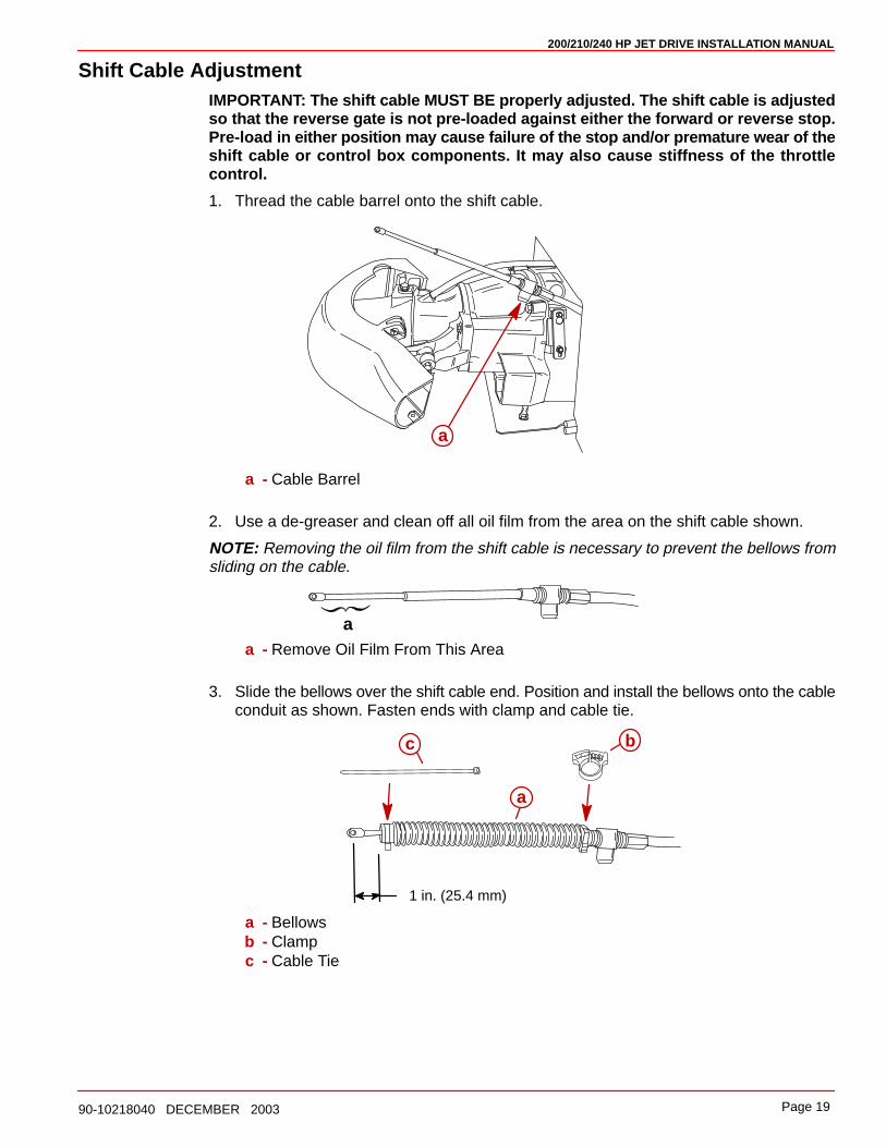
Shift Cable AdjustmentIMPORTANT: The shift cable MUST BE properly adjusted. The shift cable is adjustedso that the reverse gate is not pre-loaded against either the forward or reverse stop.Pre-load in either position may cause failure of the stop and/or premature wear of theshift cable or control box components. It may also cause stiffness of the throttlecontrol.
1. Thread the cable barrel onto the shift cable.
a
a - Cable Barrel
2. Use a de-greaser and clean off all oil film from the area on the shift cable shown.
NOTE: Removing the oil film from the shift cable is necessary to prevent the bellows fromsliding on the cable.
aa - Remove Oil Film From This Area
3. Slide the bellows over the shift cable end. Position and install the bellows onto the cableconduit as shown. Fasten ends with clamp and cable tie.
1 in. (25.4 mm)
a
bc
a - Bellowsb - Clampc - Cable Tie

200/210/240 HP JET DRIVE INSTALLATION MANUAL
Page 20 90-10218040 DECEMBER 2003
4. Loosen the lock nuts and unfasten the top end of the shift cable retainer.
NOTE: Locknuts do not have to be removed to open retainer.
a
b
a - Shift Cable Retainerb - Plastic Barrel Holder
5. Install shift cable end in slot of the reverse gate and secure with clevis pin, flat washer,and cotter pin. Bend over ends of cotter pin.
a
bc
a - Clevis Pinb - Flat Washerc - Cotter Pin
WARNINGThe shift cable must be adjusted correctly so that the reverse gate does not inter-fere with water flow coming out of the rudder. If the reverse gate hangs down intothe water flow, a vibration may be felt in the control box. If this occurs, reducethrottle immediately and readjust the cable. Improper adjustment may result inpump damage including loss of the reverse gate. Failure to properly adjust the shiftcable could result in loss of neutral and reverse, property damage, personal injuryor death.
200/210/240 HP JET DRIVE INSTALLATION MANUAL
Page 2190-10218040 DECEMBER 2003
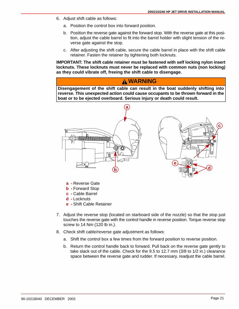
6. Adjust shift cable as follows:
a. Position the control box into forward position.
b. Position the reverse gate against the forward stop. With the reverse gate at this posi-tion, adjust the cable barrel to fit into the barrel holder with slight tension of the re-verse gate against the stop.
c. After adjusting the shift cable, secure the cable barrel in place with the shift cableretainer. Fasten the retainer by tightening both locknuts.
IMPORTANT: The shift cable retainer must be fastened with self locking nylon insertlocknuts. These locknuts must never be replaced with common nuts (non locking)as they could vibrate off, freeing the shift cable to disengage.
WARNINGDisengagement of the shift cable can result in the boat suddenly shifting intoreverse. This unexpected action could cause occupants to be thrown forward in theboat or to be ejected overboard. Serious injury or death could result.
c
de
a
b
a - Reverse Gateb - Forward Stopc - Cable Barreld - Locknutse - Shift Cable Retainer
7. Adjust the reverse stop (located on starboard side of the nozzle) so that the stop justtouches the reverse gate with the control handle in reverse position. Torque reverse stopscrew to 14 Nm (120 lb in.).
8. Check shift cable/reverse gate adjustment as follows:
a. Shift the control box a few times from the forward position to reverse position.
b. Return the control handle back to forward. Pull back on the reverse gate gently totake slack out of the cable. Check for the 9.5 to 12.7 mm (3/8 to 1/2 in.) clearancespace between the reverse gate and rudder. If necessary, readjust the cable barrel.
200/210/240 HP JET DRIVE INSTALLATION MANUAL
Page 22 90-10218040 DECEMBER 2003
9. Seal the thru-hull fitting to prevent any water leaks.
a
a - Steering Cable Thru-Hull Fitting
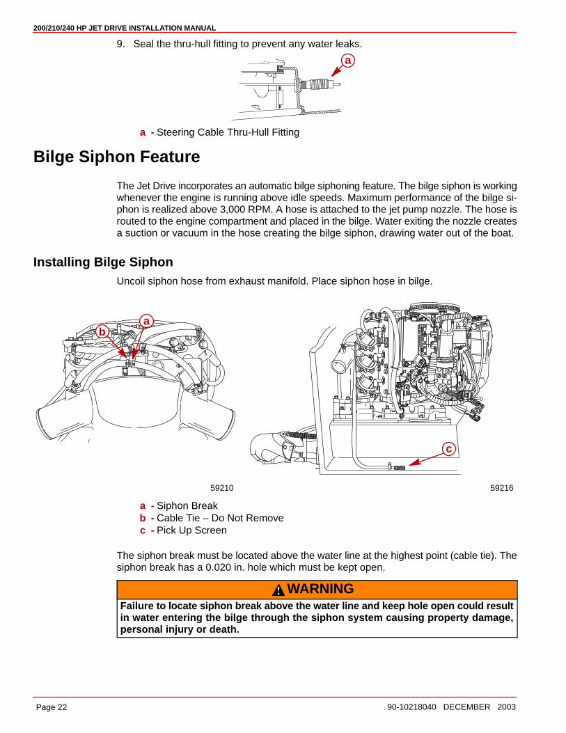
Bilge Siphon Feature
The Jet Drive incorporates an automatic bilge siphoning feature. The bilge siphon is workingwhenever the engine is running above idle speeds. Maximum performance of the bilge si-phon is realized above 3,000 RPM. A hose is attached to the jet pump nozzle. The hose isrouted to the engine compartment and placed in the bilge. Water exiting the nozzle createsa suction or vacuum in the hose creating the bilge siphon, drawing water out of the boat.
Installing Bilge SiphonUncoil siphon hose from exhaust manifold. Place siphon hose in bilge.
c
59216
ab
59210
a - Siphon Breakb - Cable Tie – Do Not Removec - Pick Up Screen
The siphon break must be located above the water line at the highest point (cable tie). Thesiphon break has a 0.020 in. hole which must be kept open.
WARNINGFailure to locate siphon break above the water line and keep hole open could resultin water entering the bilge through the siphon system causing property damage,personal injury or death.
200/210/240 HP JET DRIVE INSTALLATION MANUAL
Page 2390-10218040 DECEMBER 2003
Water By-Pass System
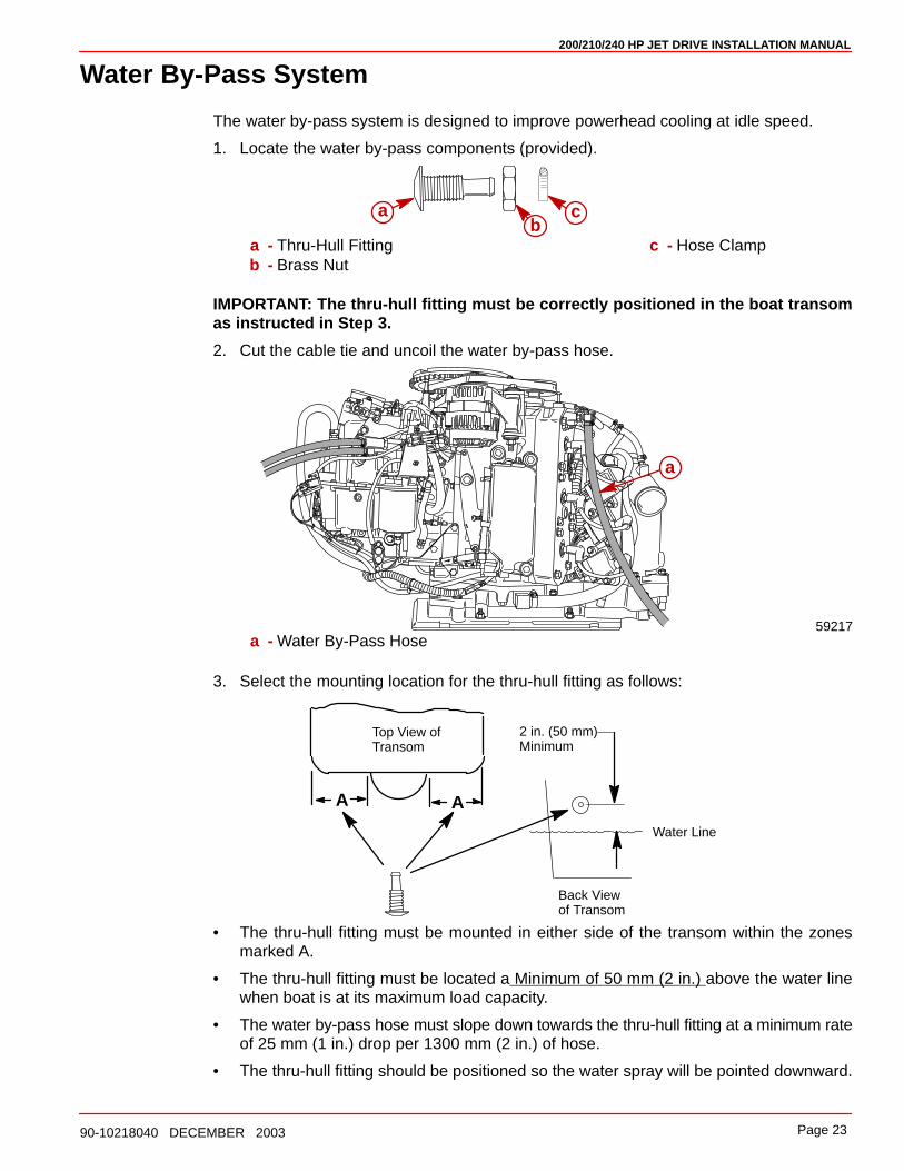
The water by-pass system is designed to improve powerhead cooling at idle speed.
1. Locate the water by-pass components (provided).
ab
c
a - Thru-Hull Fittingb - Brass Nut
c - Hose Clamp
IMPORTANT: The thru-hull fitting must be correctly positioned in the boat transomas instructed in Step 3.
2. Cut the cable tie and uncoil the water by-pass hose.
59217
a
a - Water By-Pass Hose
3. Select the mounting location for the thru-hull fitting as follows:
A
2 in. (50 mm) Minimum
Top View ofTransom
A
Back Viewof Transom
Water Line
• The thru-hull fitting must be mounted in either side of the transom within the zonesmarked A.
• The thru-hull fitting must be located a Minimum of 50 mm (2 in.) above the water linewhen boat is at its maximum load capacity.
• The water by-pass hose must slope down towards the thru-hull fitting at a minimum rateof 25 mm (1 in.) drop per 1300 mm (2 in.) of hose.
• The thru-hull fitting should be positioned so the water spray will be pointed downward.
200/210/240 HP JET DRIVE INSTALLATION MANUAL
Page 24 90-10218040 DECEMBER 2003
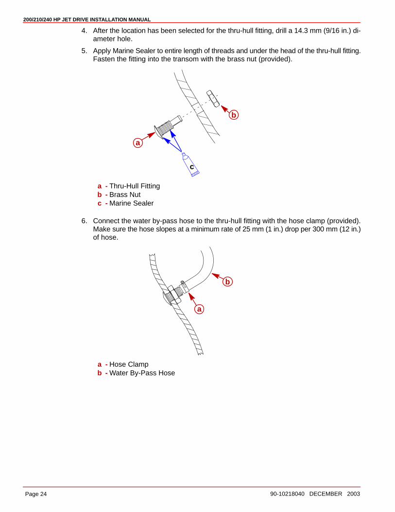
4. After the location has been selected for the thru-hull fitting, drill a 14.3 mm (9/16 in.) di-ameter hole.
5. Apply Marine Sealer to entire length of threads and under the head of the thru-hull fitting.Fasten the fitting into the transom with the brass nut (provided).
c
a
b
a - Thru-Hull Fittingb - Brass Nutc - Marine Sealer
6. Connect the water by-pass hose to the thru-hull fitting with the hose clamp (provided).Make sure the hose slopes at a minimum rate of 25 mm (1 in.) drop per 300 mm (12 in.)of hose.
a
b
a - Hose Clampb - Water By-Pass Hose
200/210/240 HP JET DRIVE INSTALLATION MANUAL
Page 2590-10218040 DECEMBER 2003
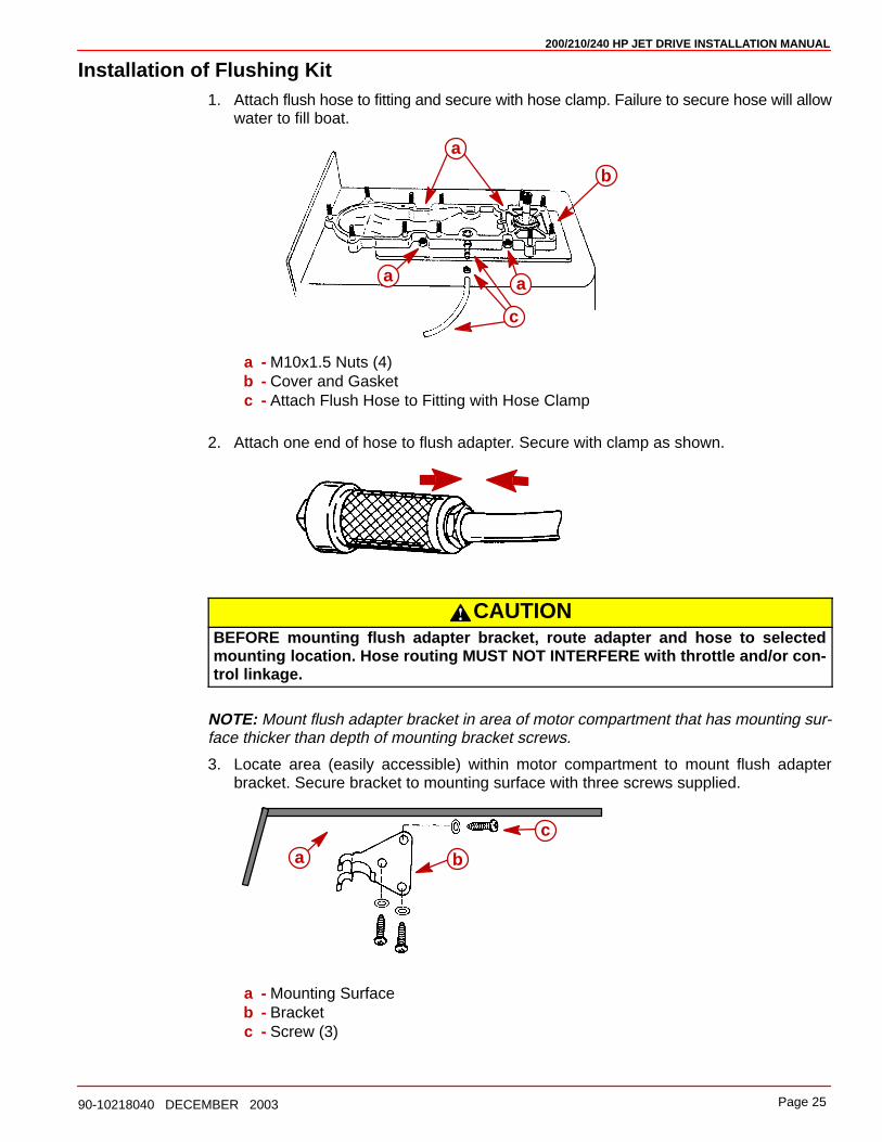
Installation of Flushing Kit1. Attach flush hose to fitting and secure with hose clamp. Failure to secure hose will allow
water to fill boat.
a
b
aa
c
a - M10x1.5 Nuts (4)b - Cover and Gasketc - Attach Flush Hose to Fitting with Hose Clamp
2. Attach one end of hose to flush adapter. Secure with clamp as shown.
CAUTIONBEFORE mounting flush adapter bracket, route adapter and hose to selectedmounting location. Hose routing MUST NOT INTERFERE with throttle and/or con-trol linkage.
NOTE: Mount flush adapter bracket in area of motor compartment that has mounting sur-face thicker than depth of mounting bracket screws.
3. Locate area (easily accessible) within motor compartment to mount flush adapterbracket. Secure bracket to mounting surface with three screws supplied.
a b
c
a - Mounting Surfaceb - Bracketc - Screw (3)
200/210/240 HP JET DRIVE INSTALLATION MANUAL
Page 26 90-10218040 DECEMBER 2003
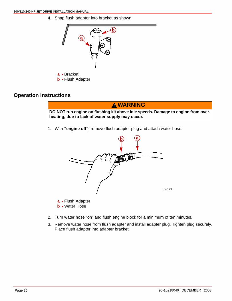
4. Snap flush adapter into bracket as shown.
a
b
a - Bracketb - Flush Adapter
Operation Instructions
WARNINGDO NOT run engine on flushing kit above idle speeds. Damage to engine from over-heating, due to lack of water supply may occur.
1. With “engine off” , remove flush adapter plug and attach water hose.
52121
ab
a - Flush Adapterb - Water Hose
2. Turn water hose “on” and flush engine block for a minimum of ten minutes.
3. Remove water hose from flush adapter and install adapter plug. Tighten plug securely.Place flush adapter into adapter bracket.
200/210/240 HP JET DRIVE INSTALLATION MANUAL
Page 2790-10218040 DECEMBER 2003
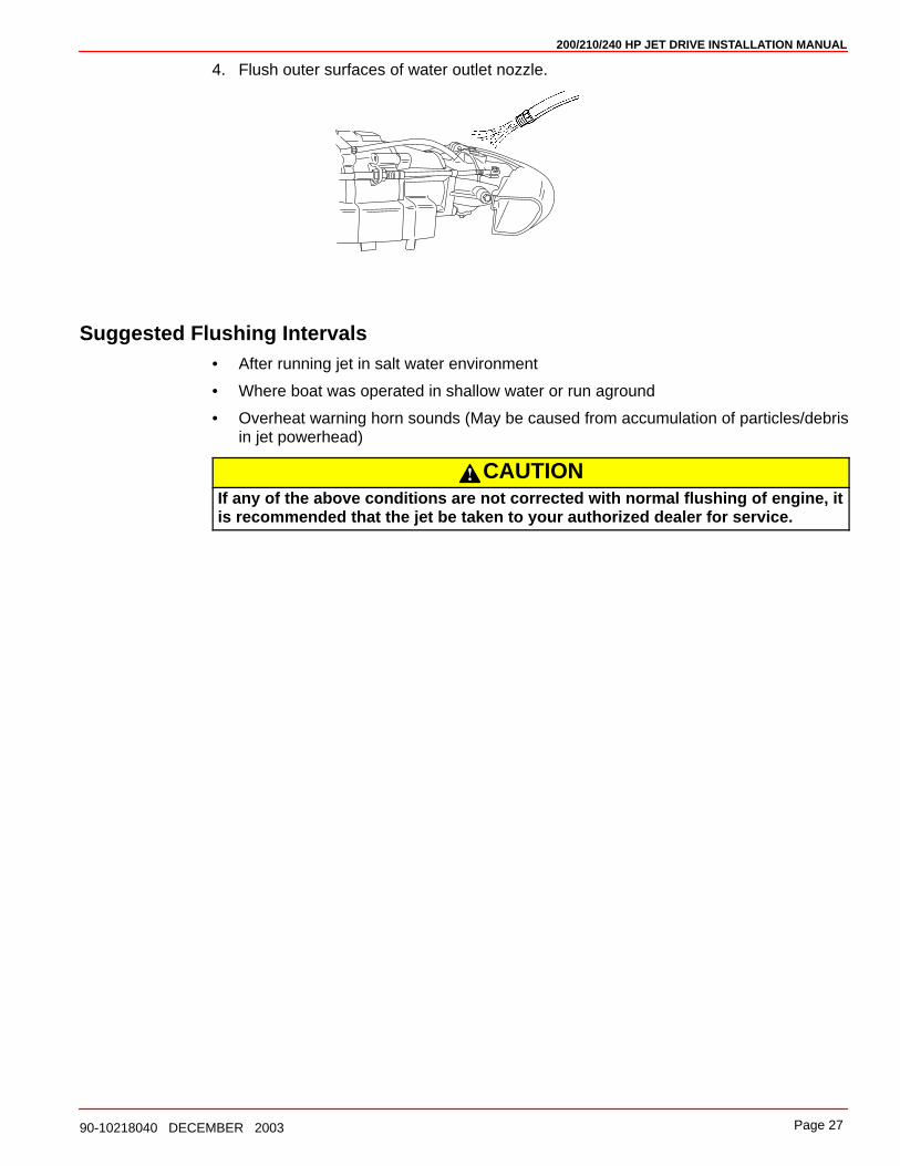
4. Flush outer surfaces of water outlet nozzle.
Suggested Flushing Intervals• After running jet in salt water environment
• Where boat was operated in shallow water or run aground
• Overheat warning horn sounds (May be caused from accumulation of particles/debrisin jet powerhead)
CAUTIONIf any of the above conditions are not corrected with normal flushing of engine, itis recommended that the jet be taken to your authorized dealer for service.
200/210/240 HP JET DRIVE INSTALLATION MANUAL
Page 28 90-10218040 DECEMBER 2003
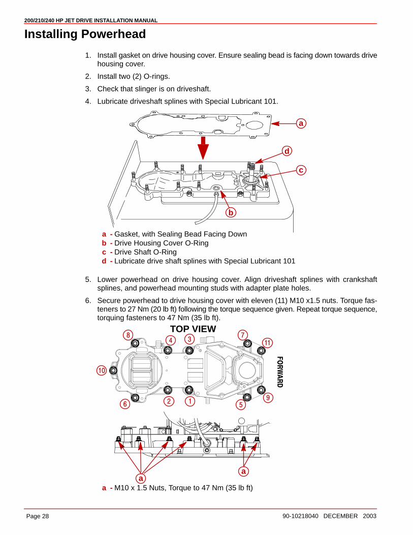
Installing Powerhead
1. Install gasket on drive housing cover. Ensure sealing bead is facing down towards drivehousing cover.
2. Install two (2) O-rings.
3. Check that slinger is on driveshaft.
4. Lubricate driveshaft splines with Special Lubricant 101.
a
b
c
d
a - Gasket, with Sealing Bead Facing Downb - Drive Housing Cover O-Ringc - Drive Shaft O-Ringd - Lubricate drive shaft splines with Special Lubricant 101
5. Lower powerhead on drive housing cover. Align driveshaft splines with crankshaftsplines, and powerhead mounting studs with adapter plate holes.
6. Secure powerhead to drive housing cover with eleven (11) M10 x1.5 nuts. Torque fas-teners to 27 Nm (20 lb ft) following the torque sequence given. Repeat torque sequence,torquing fasteners to 47 Nm (35 lb ft).
TOP VIEW
FORWARD
aa
2 1
34
56
78
9
10
11
a - M10 x 1.5 Nuts, Torque to 47 Nm (35 lb ft)
200/210/240 HP JET DRIVE INSTALLATION MANUAL
Page 2990-10218040 DECEMBER 2003
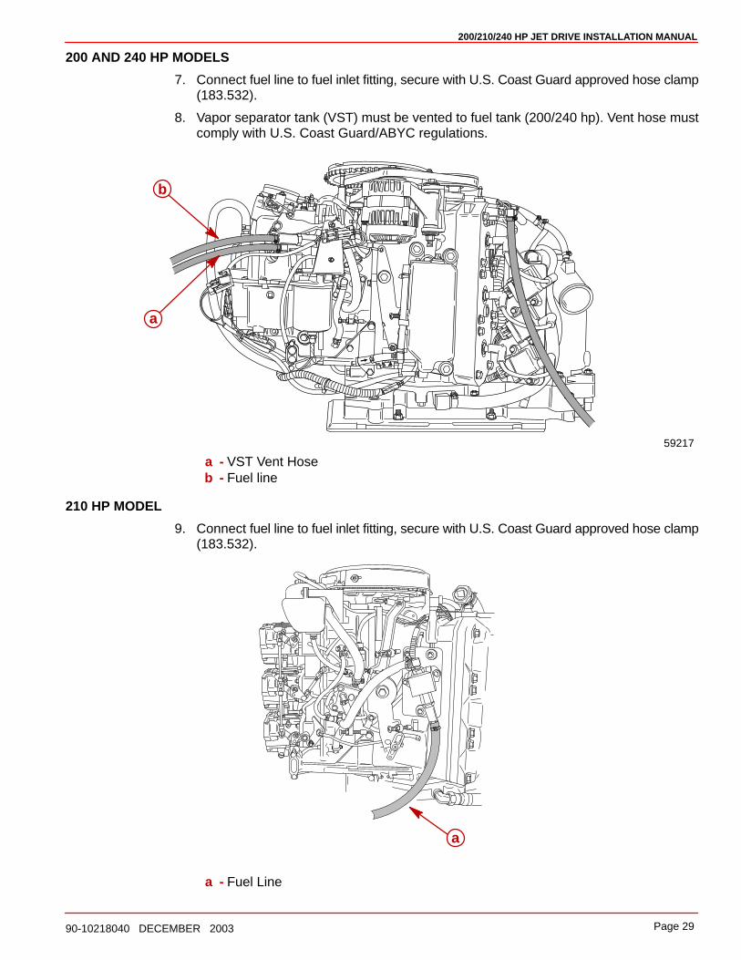
200 AND 240 HP MODELS
7. Connect fuel line to fuel inlet fitting, secure with U.S. Coast Guard approved hose clamp(183.532).
8. Vapor separator tank (VST) must be vented to fuel tank (200/240 hp). Vent hose mustcomply with U.S. Coast Guard/ABYC regulations.
59217
b
a
a - VST Vent Hoseb - Fuel line
210 HP MODEL
9. Connect fuel line to fuel inlet fitting, secure with U.S. Coast Guard approved hose clamp(183.532).
a
a - Fuel Line
200/210/240 HP JET DRIVE INSTALLATION MANUAL
Page 30 90-10218040 DECEMBER 2003
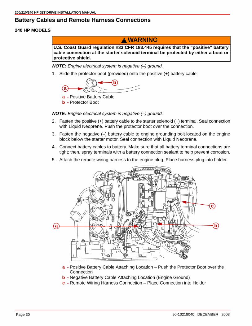
Battery Cables and Remote Harness Connections
240 HP MODELS
WARNINGU.S. Coast Guard regulation #33 CFR 183.445 requires that the “positive” batterycable connection at the starter solenoid terminal be protected by either a boot orprotective shield.
NOTE: Engine electrical system is negative (–) ground.
1. Slide the protector boot (provided) onto the positive (+) battery cable.
ab
a - Positive Battery Cableb - Protector Boot
NOTE: Engine electrical system is negative (–) ground.
2. Fasten the positive (+) battery cable to the starter solenoid (+) terminal. Seal connectionwith Liquid Neoprene. Push the protector boot over the connection.
3. Fasten the negative (–) battery cable to engine grounding bolt located on the engineblock below the starter motor. Seal connection with Liquid Neoprene.
4. Connect battery cables to battery. Make sure that all battery terminal connections aretight; then, spray terminals with a battery connection sealant to help prevent corrosion.
5. Attach the remote wiring harness to the engine plug. Place harness plug into holder.
c
a b
a - Positive Battery Cable Attaching Location – Push the Protector Boot over theConnection
b - Negative Battery Cable Attaching Location (Engine Ground)c - Remote Wiring Harness Connection – Place Connection into Holder

200/210/240 HP JET DRIVE INSTALLATION MANUAL
Page 3190-10218040 DECEMBER 2003
Battery Cables and Remote Harness Connections
200 HP MODELS
WARNINGU.S. Coast Guard regulation #33 CFR 183.445 requires that the “positive” batterycable connection at the starter solenoid terminal be protected by either a boot orprotective shield.
NOTE: Engine electrical system is negative (–) ground.
1. Slide the protector boot (provided) onto the positive (+) battery cable.
ab
a - Positive Battery Cableb - Protector Boot
NOTE: Engine electrical system is negative (–) ground.
2. Fasten the positive (+) battery cable to the starter solenoid (+) terminal. Seal connectionwith Liquid Neoprene. Push the protector boot over the connection.
3. Fasten the negative (–) battery cable to engine grounding bolt located on the engineblock below the starter motor. Seal connection with Liquid Neoprene.
4. Connect battery cables to battery. Make sure that all battery terminal connections aretight; then, spray terminals with a battery connection sealant to help retard corrosion.
5. Attach the remote wiring harness to the engine plug. Place harness plug into holder.
c
a
b
a - Positive Battery Cable Attaching Location – Push the Protector Boot over theConnection
b - Negative Battery Cable Attaching Location (Engine Ground)c - Remote Wiring Harness Connection – Place Connection into Holder
200/210/240 HP JET DRIVE INSTALLATION MANUAL
Page 32 90-10218040 DECEMBER 2003
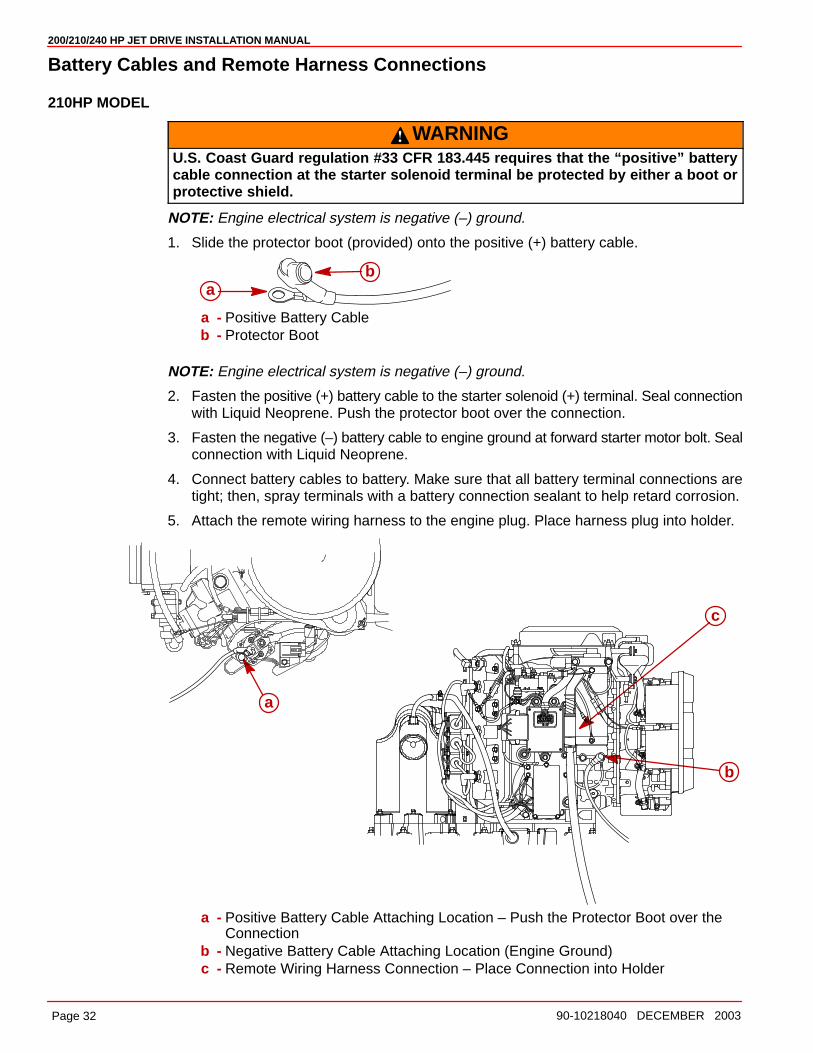
Battery Cables and Remote Harness Connections
210HP MODEL
WARNINGU.S. Coast Guard regulation #33 CFR 183.445 requires that the “positive” batterycable connection at the starter solenoid terminal be protected by either a boot orprotective shield.
NOTE: Engine electrical system is negative (–) ground.
1. Slide the protector boot (provided) onto the positive (+) battery cable.
ab
a - Positive Battery Cableb - Protector Boot
NOTE: Engine electrical system is negative (–) ground.
2. Fasten the positive (+) battery cable to the starter solenoid (+) terminal. Seal connectionwith Liquid Neoprene. Push the protector boot over the connection.
3. Fasten the negative (–) battery cable to engine ground at forward starter motor bolt. Sealconnection with Liquid Neoprene.
4. Connect battery cables to battery. Make sure that all battery terminal connections aretight; then, spray terminals with a battery connection sealant to help retard corrosion.
5. Attach the remote wiring harness to the engine plug. Place harness plug into holder.
c
a
b
a - Positive Battery Cable Attaching Location – Push the Protector Boot over theConnection
b - Negative Battery Cable Attaching Location (Engine Ground)c - Remote Wiring Harness Connection – Place Connection into Holder
200/210/240 HP JET DRIVE INSTALLATION MANUAL
Page 3390-10218040 DECEMBER 2003
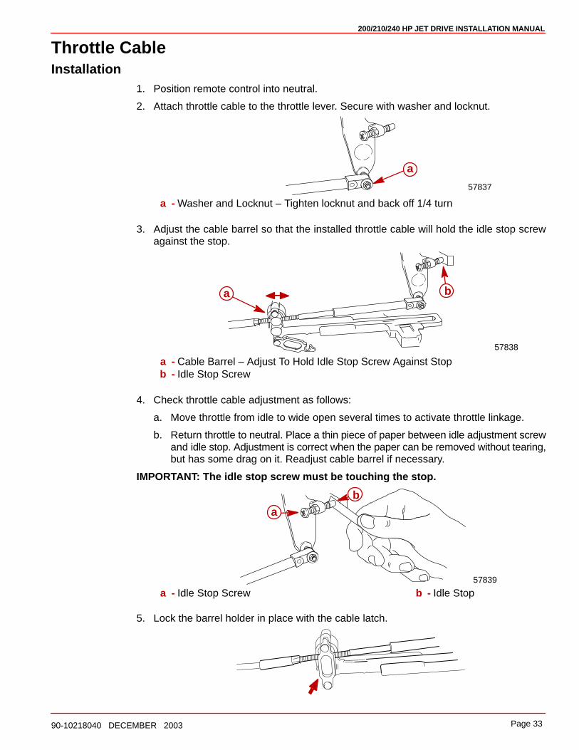
Throttle CableInstallation
1. Position remote control into neutral.
2. Attach throttle cable to the throttle lever. Secure with washer and locknut.
a
57837
a - Washer and Locknut – Tighten locknut and back off 1/4 turn
3. Adjust the cable barrel so that the installed throttle cable will hold the idle stop screwagainst the stop.
a b
57838
a - Cable Barrel – Adjust To Hold Idle Stop Screw Against Stopb - Idle Stop Screw
4. Check throttle cable adjustment as follows:
a. Move throttle from idle to wide open several times to activate throttle linkage.
b. Return throttle to neutral. Place a thin piece of paper between idle adjustment screwand idle stop. Adjustment is correct when the paper can be removed without tearing,but has some drag on it. Readjust cable barrel if necessary.
IMPORTANT: The idle stop screw must be touching the stop.
ab
57839
a - Idle Stop Screw b - Idle Stop
5. Lock the barrel holder in place with the cable latch.
200/210/240 HP JET DRIVE INSTALLATION MANUAL
Page 34 90-10218040 DECEMBER 2003
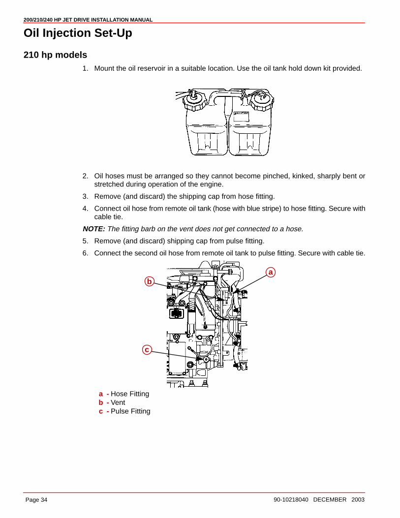
Oil Injection Set-Up
210 hp models1. Mount the oil reservoir in a suitable location. Use the oil tank hold down kit provided.
2. Oil hoses must be arranged so they cannot become pinched, kinked, sharply bent orstretched during operation of the engine.
3. Remove (and discard) the shipping cap from hose fitting.
4. Connect oil hose from remote oil tank (hose with blue stripe) to hose fitting. Secure withcable tie.
NOTE: The fitting barb on the vent does not get connected to a hose.
5. Remove (and discard) shipping cap from pulse fitting.
6. Connect the second oil hose from remote oil tank to pulse fitting. Secure with cable tie.
ab
c
a - Hose Fittingb - Ventc - Pulse Fitting
200/210/240 HP JET DRIVE INSTALLATION MANUAL
Page 3590-10218040 DECEMBER 2003
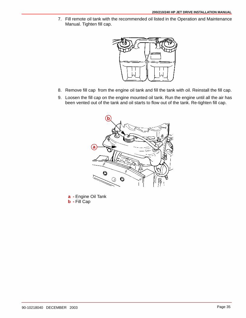
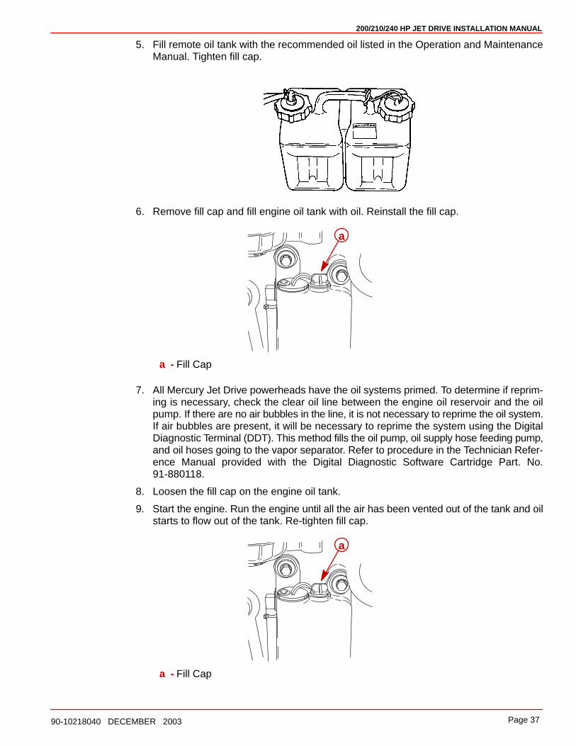
7. Fill remote oil tank with the recommended oil listed in the Operation and MaintenanceManual. Tighten fill cap.
8. Remove fill cap from the engine oil tank and fill the tank with oil. Reinstall the fill cap.
9. Loosen the fill cap on the engine mounted oil tank. Run the engine until all the air hasbeen vented out of the tank and oil starts to flow out of the tank. Re-tighten fill cap.
a
b
a - Engine Oil Tankb - Fill Cap
200/210/240 HP JET DRIVE INSTALLATION MANUAL
Page 36 90-10218040 DECEMBER 2003
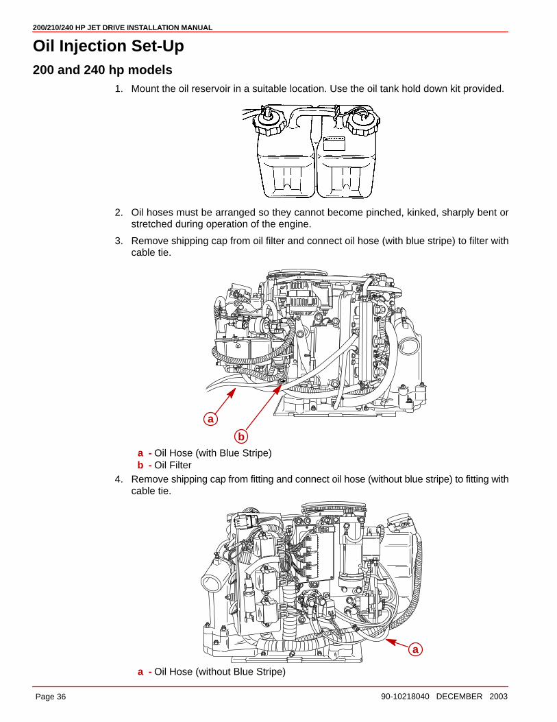
Oil Injection Set-Up200 and 240 hp models
1. Mount the oil reservoir in a suitable location. Use the oil tank hold down kit provided.
2. Oil hoses must be arranged so they cannot become pinched, kinked, sharply bent orstretched during operation of the engine.
3. Remove shipping cap from oil filter and connect oil hose (with blue stripe) to filter withcable tie.
a
ba - Oil Hose (with Blue Stripe)b - Oil Filter
4. Remove shipping cap from fitting and connect oil hose (without blue stripe) to fitting withcable tie.
a
a - Oil Hose (without Blue Stripe)
200/210/240 HP JET DRIVE INSTALLATION MANUAL
Page 3790-10218040 DECEMBER 2003
5. Fill remote oil tank with the recommended oil listed in the Operation and MaintenanceManual. Tighten fill cap.
6. Remove fill cap and fill engine oil tank with oil. Reinstall the fill cap.
a
a - Fill Cap
7. All Mercury Jet Drive powerheads have the oil systems primed. To determine if reprim-ing is necessary, check the clear oil line between the engine oil reservoir and the oilpump. If there are no air bubbles in the line, it is not necessary to reprime the oil system.If air bubbles are present, it will be necessary to reprime the system using the DigitalDiagnostic Terminal (DDT). This method fills the oil pump, oil supply hose feeding pump,and oil hoses going to the vapor separator. Refer to procedure in the Technician Refer-ence Manual provided with the Digital Diagnostic Software Cartridge Part. No.91-880118.
8. Loosen the fill cap on the engine oil tank.
9. Start the engine. Run the engine until all the air has been vented out of the tank and oilstarts to flow out of the tank. Re-tighten fill cap.
a
a - Fill Cap
200/210/240 HP JET DRIVE INSTALLATION MANUAL
Page 38 90-10218040 DECEMBER 2003
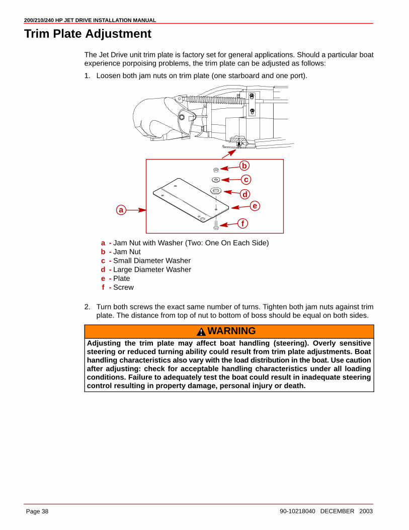
Trim Plate Adjustment
The Jet Drive unit trim plate is factory set for general applications. Should a particular boatexperience porpoising problems, the trim plate can be adjusted as follows:
1. Loosen both jam nuts on trim plate (one starboard and one port).
a
b
c
de
f
a - Jam Nut with Washer (Two: One On Each Side)b - Jam Nutc - Small Diameter Washerd - Large Diameter Washere - Platef - Screw
2. Turn both screws the exact same number of turns. Tighten both jam nuts against trimplate. The distance from top of nut to bottom of boss should be equal on both sides.
WARNINGAdjusting the trim plate may affect boat handling (steering). Overly sensitivesteering or reduced turning ability could result from trim plate adjustments. Boathandling characteristics also vary with the load distribution in the boat. Use cautionafter adjusting: check for acceptable handling characteristics under all loadingconditions. Failure to adequately test the boat could result in inadequate steeringcontrol resulting in property damage, personal injury or death.

200/210/240 HP JET DRIVE INSTALLATION MANUAL
Page 3990-10218040 DECEMBER 2003
Exhaust System Installation
General Exhaust System Notes1. Exhaust system application must meet ABYC standard P-1 for marine exhaust installa-
tions.
2. The entire exhaust system must meet 1309.99 kPa (190 psi) burst pressure.
3. All rubberized exhaust system components must meet SAE J-2006 standards for ma-rine exhaust hoses.
CAUTIONMufflers must be secured in such a way as to prevent muffler movement during in-advertent engine backfire. Movement of mufflers may result in exhaust hose loos-ening which could cause boat sinking due to water intrusion.
4. The mufflers and exhaust hoses must be adequately supported for proper orientationand to prevent overstressing the exhaust components. The support requirements willvary with exhaust system design and the amount of G-forces to be encountered.
5. Rubber hose should be connected to pipes with flares or beads or barbs to prevent thehose from sliding off the pipe under pressure.
6. For additional exhaust system recommendations, see MERCURY spec. 90-884386which covers all jet drive exhaust applications not covered under these guidelines.
Exhaust Outlet Measurement Procedure1. Fill all fuel, oil and water tanks to maximum capacity.
2. Add maximum allowable cargo weight to boat in areas where it will be stored.
3. Add 86 kg (190 lbs) of weight in all locations where each passenger will sit during normaloperation.
4. Using diagrams provided (following), measure to ensure location of muffler outlets.
5. Move load weight and cargo weight to stern of boat to simulate greatest stern down atti-tude the boat will encounter such as when loading.
6. Recheck muffler outlet measurements.
7. Check exhaust system slope to ensure 5° down hill slope.
200/210/240 HP JET DRIVE INSTALLATION MANUAL
Page 40 90-10218040 DECEMBER 2003
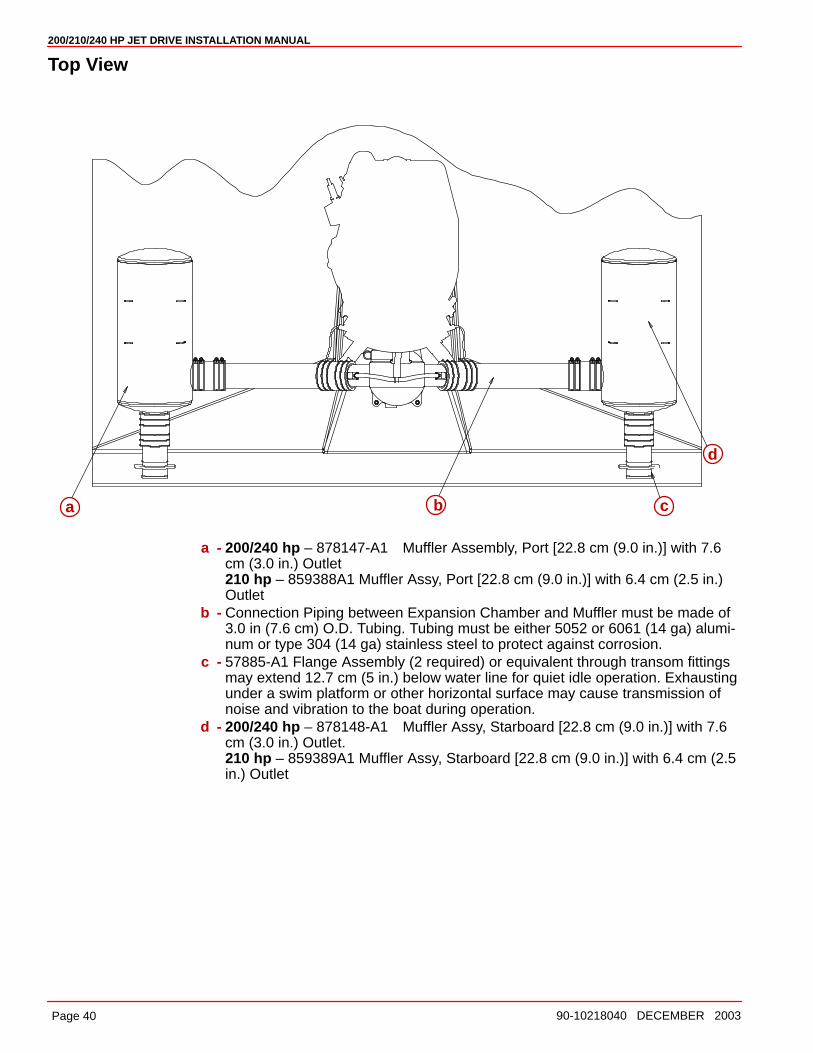
Top View
a b c
d
a - 200/240 hp – 878147-A1 Muffler Assembly, Port [22.8 cm (9.0 in.)] with 7.6cm (3.0 in.) Outlet210 hp – 859388A1 Muffler Assy, Port [22.8 cm (9.0 in.)] with 6.4 cm (2.5 in.)Outlet
b - Connection Piping between Expansion Chamber and Muffler must be made of3.0 in (7.6 cm) O.D. Tubing. Tubing must be either 5052 or 6061 (14 ga) alumi-num or type 304 (14 ga) stainless steel to protect against corrosion.
c - 57885-A1 Flange Assembly (2 required) or equivalent through transom fittingsmay extend 12.7 cm (5 in.) below water line for quiet idle operation. Exhaustingunder a swim platform or other horizontal surface may cause transmission ofnoise and vibration to the boat during operation.
d - 200/240 hp – 878148-A1 Muffler Assy, Starboard [22.8 cm (9.0 in.)] with 7.6cm (3.0 in.) Outlet.210 hp – 859389A1 Muffler Assy, Starboard [22.8 cm (9.0 in.)] with 6.4 cm (2.5in.) Outlet
200/210/240 HP JET DRIVE INSTALLATION MANUAL
Page 4190-10218040 DECEMBER 2003
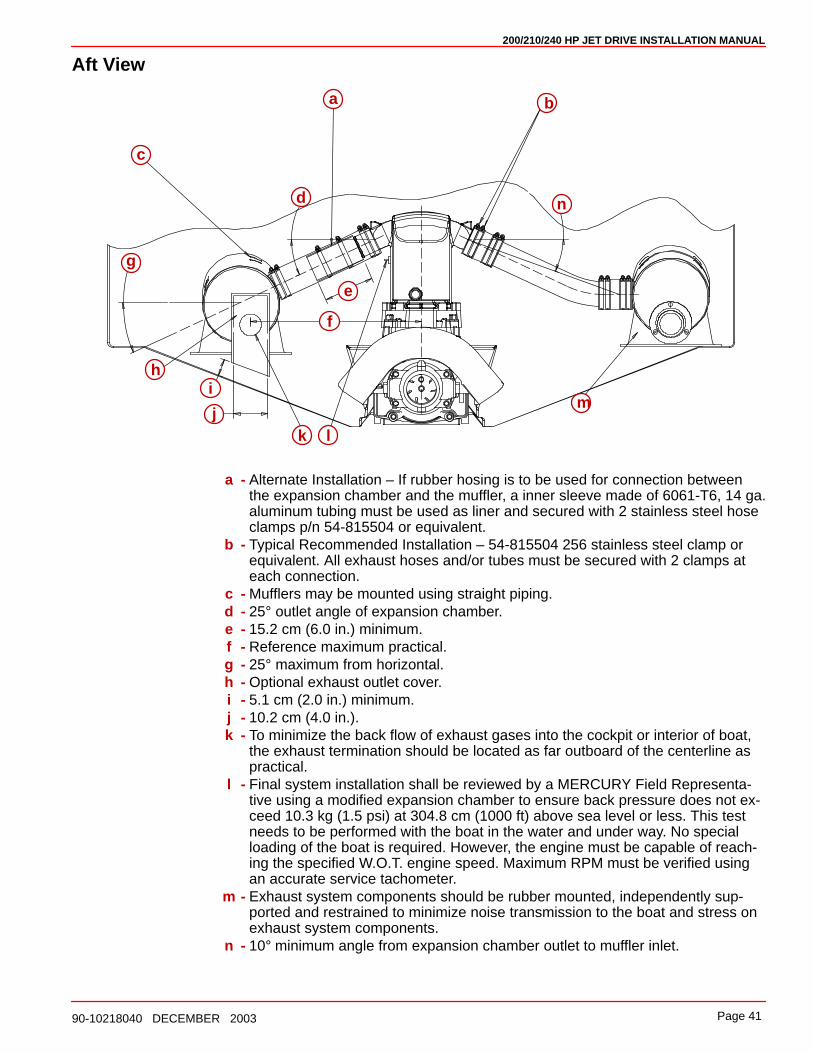
Aft View
a b
c
d
e
f
g
hi
jk l
m
n
a - Alternate Installation – If rubber hosing is to be used for connection betweenthe expansion chamber and the muffler, a inner sleeve made of 6061-T6, 14 ga.aluminum tubing must be used as liner and secured with 2 stainless steel hoseclamps p/n 54-815504 or equivalent.
b - Typical Recommended Installation – 54-815504 256 stainless steel clamp orequivalent. All exhaust hoses and/or tubes must be secured with 2 clamps ateach connection.
c - Mufflers may be mounted using straight piping.d - 25° outlet angle of expansion chamber.e - 15.2 cm (6.0 in.) minimum.f - Reference maximum practical.g - 25° maximum from horizontal.h - Optional exhaust outlet cover.i - 5.1 cm (2.0 in.) minimum.j - 10.2 cm (4.0 in.).k - To minimize the back flow of exhaust gases into the cockpit or interior of boat,
the exhaust termination should be located as far outboard of the centerline aspractical.
l - Final system installation shall be reviewed by a MERCURY Field Representa-tive using a modified expansion chamber to ensure back pressure does not ex-ceed 10.3 kg (1.5 psi) at 304.8 cm (1000 ft) above sea level or less. This testneeds to be performed with the boat in the water and under way. No specialloading of the boat is required. However, the engine must be capable of reach-ing the specified W.O.T. engine speed. Maximum RPM must be verified usingan accurate service tachometer.
m - Exhaust system components should be rubber mounted, independently sup-ported and restrained to minimize noise transmission to the boat and stress onexhaust system components.
n - 10° minimum angle from expansion chamber outlet to muffler inlet.
200/210/240 HP JET DRIVE INSTALLATION MANUAL
Page 42 90-10218040 DECEMBER 2003
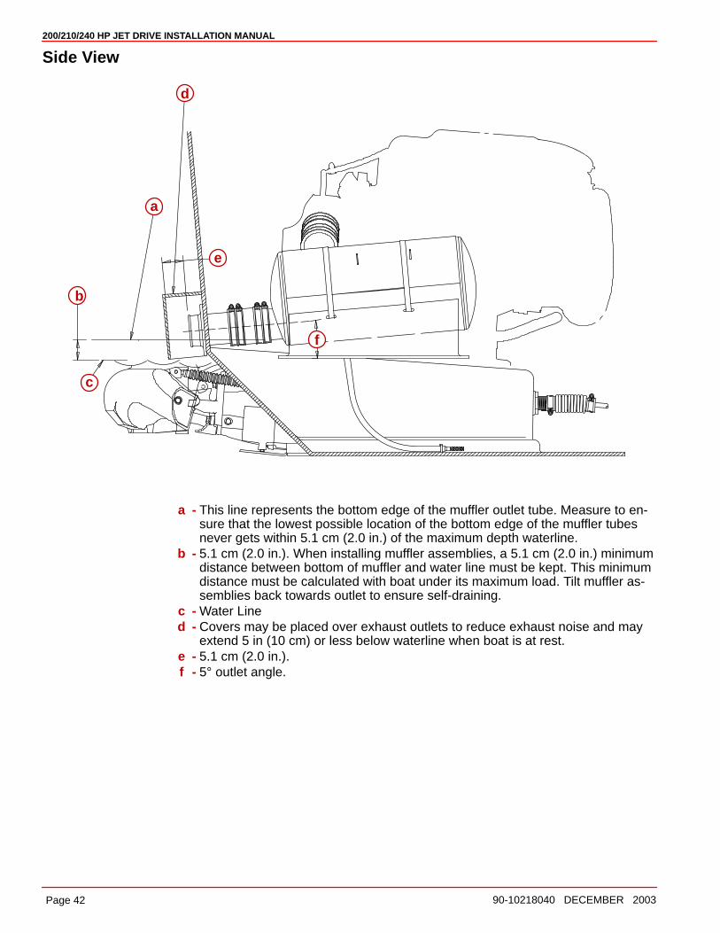
Side View
a
b
c
d
e
f
a - This line represents the bottom edge of the muffler outlet tube. Measure to en-sure that the lowest possible location of the bottom edge of the muffler tubesnever gets within 5.1 cm (2.0 in.) of the maximum depth waterline.
b - 5.1 cm (2.0 in.). When installing muffler assemblies, a 5.1 cm (2.0 in.) minimumdistance between bottom of muffler and water line must be kept. This minimumdistance must be calculated with boat under its maximum load. Tilt muffler as-semblies back towards outlet to ensure self-draining.
c - Water Lined - Covers may be placed over exhaust outlets to reduce exhaust noise and may
extend 5 in (10 cm) or less below waterline when boat is at rest.e - 5.1 cm (2.0 in.).f - 5° outlet angle.
200/210/240 HP JET DRIVE INSTALLATION MANUAL
Page 4390-10218040 DECEMBER 2003
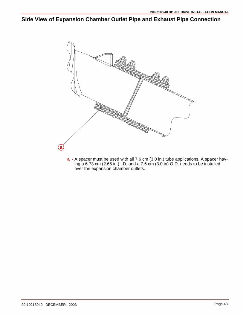
Side View of Expansion Chamber Outlet Pipe and Exhaust Pipe Connection
a
a - A spacer must be used with all 7.6 cm (3.0 in.) tube applications. A spacer hav-ing a 6.73 cm (2.65 in.) I.D. and a 7.6 cm (3.0 in) O.D. needs to be installedover the expansion chamber outlets.

200/210/240 HP JET DRIVE INSTALLATION MANUAL
Page 44 90-10218040 DECEMBER 2003
Pre-delivery Inspection
Not Check/
Applicable Adjust CHECK BEFORE RUNNING
❏ ❏ Water hose connection/torqued
❏ ❏ Cover plate & adaptor platefasteners torqued
❏ ❏ Battery meets engine specification
❏ ❏ Battery charged & secure
❏ ❏ All electrical connections tight
❏ ❏ All fuel connections tight
❏ ❏ Throttle, shift, & steering adjustedcorrectly and fasteners torqued
❏ ❏ Shift cable adjusted to keepreverse gate above rudder in forward w/ slack pulledout of cable and against the stop.
❏ ❏ Pump housing oil level full(See Owner’s Manual)
❏ ❏ Oil injection reservoir full and bled
❏ ❏ Warning system operational
ON THE WATER CHECK
❏ ❏ Starter neutral safety switchoperational
❏ ❏ Lanyard stop switch operational
❏ ❏ All gauges read properly
❏ ❏ No fuel or oil leaks
❏ ❏ No water leaks
❏ ❏ No exhaust leaks
❏ ❏ Ignition timing set to specs
❏ ❏ Idle:____________RPM
❏ ❏ Idle mixture adjusted
❏ ❏ Forward-Neutral-Reverseoperational
❏ ❏ Steering operational throughoutentire range
❏ ❏ Acceleration test
❏ ❏ WOT:___________RPM
❏ ❏ Boat handling
POST WATER CHECK
❏ ❏ Re-torque adapter plate fasteners
❏ ❏ No fuel, oil, water or exhaustleaks
❏ ❏ Re-check shift cable adjustment. Readjust as necessary