
2. The Pipeline
41
1 Computer Architecture 2013 - 2021 Feza BUZLUCA 2.1 http://akademi.itu.edu.tr/en/buzluca/ http:// www.buzluca.info 2. The Pipeline In pipelining, multiple tasks (for example, instructions) are executed in parallel. To use the pipelining approach efficiently 1. We must have tasks that are repeated many times on different data. 2. Tasks must be divided into small pieces (operations or actions) that can be performed in parallel. Example of a pipeline: an automobile assembly line. The task • is the construction of a car, • is repeated many times for different cars, • consists of some operations, such as attaching the doors, attaching the tires. Each operation • has its own station in the pipeline (assembly line). • is performed in parallel with other operations but on a different car. e.g., while a worker is attaching the doors of the i th car, another worker is attaching the tires of the (i+1) st car at the same time. License: https://creativecommons.org/licenses/by-nc-nd/4.0/ Computer Architecture 2013 - 2021 Feza BUZLUCA 2.2 http://akademi.itu.edu.tr/en/buzluca/ http:// www.buzluca.info Example: An automobile assembly line with three stations Station 1 Station 2 Station 3 Car 1 Car 2 Car 1 Step = 1 Step = 2 Car 2 Car 1 Step = 3 Car 3 Step = 4 Station 1 Station 2 Station 3 Station 1 Station 2 Station 3 Station 1 Station 2 Station 3 At the end of Step = 3 the Car 1 (Task 1) has been completed. Car 1 is ready. Car 3 Car 2 Car 4 Station 1 Station 2 Station 3 After Step = 3 (the pipeline is full), at each step, a new car (task) is completed. Car 2 is ready.
Transcript of 2. The Pipeline

1
Computer Architecture
2013 - 2021 Feza BUZLUCA 2.1http://akademi.itu.edu.tr/en/buzluca/http:// www.buzluca.info
2. The Pipeline
In pipelining, multiple tasks (for example, instructions) are executed in parallel.
To use the pipelining approach efficiently
1. We must have tasks that are repeated many times on different data.
2. Tasks must be divided into small pieces (operations or actions) that can be performed in parallel.
Example of a pipeline: an automobile assembly line.
The task
• is the construction of a car,
• is repeated many times for different cars,
• consists of some operations, such as attaching the doors, attaching the tires.
Each operation
• has its own station in the pipeline (assembly line).
• is performed in parallel with other operations but on a different car.
e.g., while a worker is attaching the doors of the ith car, another worker is attaching the tires of the (i+1)st car at the same time.
License: https://creativecommons.org/licenses/by-nc-nd/4.0/
Computer Architecture
2013 - 2021 Feza BUZLUCA 2.2http://akademi.itu.edu.tr/en/buzluca/http:// www.buzluca.info
Example: An automobile assembly line with three stations
Station 1 Station 2 Station 3
Car 1
Car 2 Car 1
Step = 1
Step = 2
Car 2 Car 1Step = 3 Car 3
Step = 4
Station 1 Station 2 Station 3
Station 1 Station 2 Station 3
Station 1 Station 2 Station 3
At the end of Step = 3 the Car 1 (Task 1) has been completed.
Car 1 is ready.
Car 3 Car 2Car 4
Station 1 Station 2 Station 3
After Step = 3 (the pipeline is full), at each step, a new car (task) is completed.
Car 2 is ready.
2
Computer Architecture
2013 - 2021 Feza BUZLUCA 2.3http://akademi.itu.edu.tr/en/buzluca/http:// www.buzluca.info
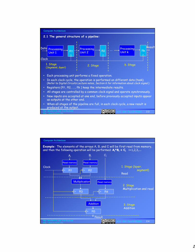
2.1 The general structure of a pipeline:
Clock
ProcessingUnit 1 R1
ProcessingUnit 2 R2
ProcessingUnit k Rk....Data Result
1. Stage(Segment, layer)
2. Stage k. Stage
• Each processing unit performs a fixed operation.
• In each clock cycle, the operation is performed on different data (task). (Refer to Digital Circuits Lecture notes, Section 6 for information about clock signal.)
• Registers (R1, R2, …, Rk ) keep the intermediate results.
• All stages are controlled by a common clock signal and operate synchronously.
• New inputs are accepted at one end, before previously accepted inputs appear as outputs at the other end.
• When all stages of the pipeline are full, in each clock cycle, a new result is produced at the output.
Computer Architecture
2013 - 2021 Feza BUZLUCA 2.4http://akademi.itu.edu.tr/en/buzluca/http:// www.buzluca.info
Example: The elements of the arrays A, B, and C will be first read from memory,and then the following operation will be performed: Ai*Bi + Ci i=1,2,3,...
1. Stage (layer,segment)
Read
2. StageMultiplication and read
3. StageAddition
Multiplication
R3 R4
Ci
Read memory
R1
Ai
R2
Bi
Clock
Read memoryRead memory
Addition
R5
Result

3
Computer Architecture
2013 - 2021 Feza BUZLUCA 2.5http://akademi.itu.edu.tr/en/buzluca/http:// www.buzluca.info
Clock cycle 1. Stage (Read) 2. Stage(Multiply) 3.Stage (Add)R1 R2 R3 R4 R5
1 A1 B1 - - -2 A2 B2 A1*B1 C1 -3 A3 B3 A2*B2 C2 A1*B1 + C1 (First result)4 A4 B4 A3*B3 C3 A2*B2 + C2 (2nd result)5 A5 B5 A4*B4 C4 A3*B3 + C3 (3rd result)
• In this example, the task is decomposed into 3 operations: Reading, multiplication, and addition.
• We assume that arrays are in separate memory modules, which can be read in parallel.
• We start to read elements of array C one clock cycle after reading A and B.
Functioning of the pipeline with three stages:
Note: • Assuming that the time to access the memory is significantly shorter than the
durations of the other operations and the data is always ready to be read, reading is not treated as a separate operation.
• In this case, the pipeline could be designed with two stages which perform only arithmetical operations: multiplication and addition.
Example (cont'd):
Computer Architecture
2013 - 2021 Feza BUZLUCA 2.6http://akademi.itu.edu.tr/en/buzluca/http:// www.buzluca.info
T1
Clock Cycles (steps)
Sta
ges
6
S4
S3
S2
S1
754321
Time
T2T1
T3
T2
T1
T6
T5
T4
T3
T6
T5
T4
2.2 Space-Time Diagram of a pipeline with four stages
T4
T3
T2
T1
The 1st task (T1) is completed in 4 clock cycles (number of stages k=4).
T5
T4
T3
T2
After the kth cycle, a new task is completed in each clock cycle.
Space-time diagrams (or timing diagrams) show which task is currently being processed in which stage of the pipeline.
In the exemplary diagram below, clock cycles (steps) are the column labels, stages are the row labels (Si) , and task numbers (Ti) are the table entries.
Example:(4 stages)
Four tasks (T4) have been completed in 7 clock cycles.

4
Computer Architecture
2013 - 2021 Feza BUZLUCA 2.7http://akademi.itu.edu.tr/en/buzluca/http:// www.buzluca.info
Clock Cycles (steps)
Tas
ks
6
T4
T3
T2
S1T1
754321
S2S1
S3
S2
S1 S4
S3 S4
S4
S3
S2
S1
The 1st task (T1) is completed in 4 clock cycles (number of stages k=4)
S4
S3
S2
After the kth cycle, a new task is completed in each clock cycle
We could also construct the space-time diagram in an alternative way.
In the diagram below, clock cycles (steps) are the column labels, tasks (Ti) are the row labels, and stages (Si) are the table entries.
Space-Time Diagram of a pipeline with four stages, cont’d
Four tasks (T4) have been completed in 7 clock cycles.
Time
License: https://creativecommons.org/licenses/by-nc-nd/4.0/
Computer Architecture
2013 - 2021 Feza BUZLUCA 2.8http://akademi.itu.edu.tr/en/buzluca/http:// www.buzluca.info
2.3 Throughput and Speedup provided by the pipeline
Since all stages proceed at the same time, the time (delay) required for the slowest stage determines the length of the period of the clock signal (cycle time).
The cycle time (the period of the clock) tp can be determined as follows:
tp= max(τi) + dr = τM + dr
tp: cycle time
τi : time delay of the circuitry in the ith stage
τM : maximum stage delay (the slowest stage)
dr : time delay of the register
5
Computer Architecture
2013 - 2021 Feza BUZLUCA 2.9http://akademi.itu.edu.tr/en/buzluca/http:// www.buzluca.info
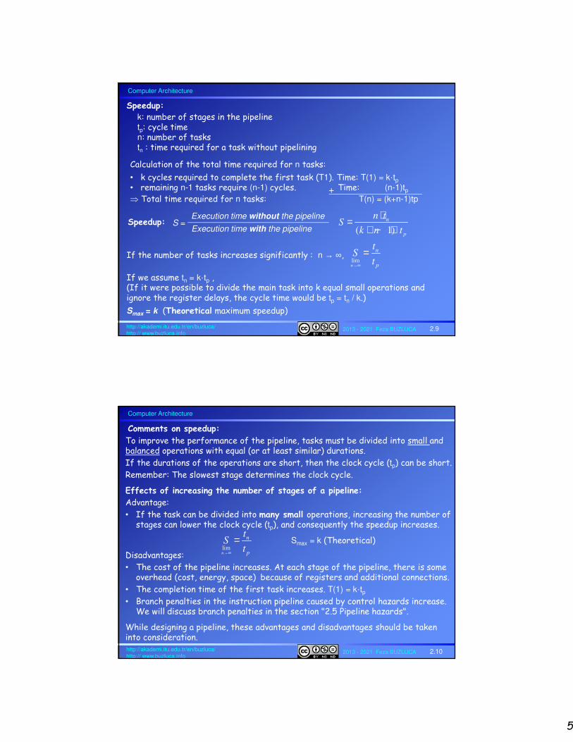
k: number of stages in the pipelinetp: cycle timen: number of taskstn : time required for a task without pipelining
( 1)
n
p
n tS
k n t
⋅=+ − ⋅
limn
n
p
tS
t→∞
=
If we assume tn = k·tp ,(If it were possible to divide the main task into k equal small operations and ignore the register delays, the cycle time would be tp = tn / k.)
Smax = k (Theoretical maximum speedup)
If the number of tasks increases significantly : n → ∞,
Speedup:
Speedup:Execution time without the pipeline
Execution time with the pipelineS =
Calculation of the total time required for n tasks:
• k cycles required to complete the first task (T1). Time: T(1) = k·tp• remaining n-1 tasks require (n-1) cycles. Time: (n-1)tp Total time required for n tasks: T(n) = (k+n-1)tp
+
Computer Architecture
2013 - 2021 Feza BUZLUCA 2.10http://akademi.itu.edu.tr/en/buzluca/http:// www.buzluca.info
To improve the performance of the pipeline, tasks must be divided into small and balanced operations with equal (or at least similar) durations.
If the durations of the operations are short, then the clock cycle (tp) can be short.
Remember: The slowest stage determines the clock cycle.
Effects of increasing the number of stages of a pipeline:
Advantage:
• If the task can be divided into many small operations, increasing the number of stages can lower the clock cycle (tp), and consequently the speedup increases.
Smax = k (Theoretical)
Disadvantages:
• The cost of the pipeline increases. At each stage of the pipeline, there is some overhead (cost, energy, space) because of registers and additional connections.
• The completion time of the first task increases. T(1) = k·tp• Branch penalties in the instruction pipeline caused by control hazards increase.
We will discuss branch penalties in the section "2.5 Pipeline hazards".
While designing a pipeline, these advantages and disadvantages should be taken into consideration.
Comments on speedup:
limn
n
p
tS
t→∞
=

6
Computer Architecture
2013 - 2021 Feza BUZLUCA 2.11http://akademi.itu.edu.tr/en/buzluca/http:// www.buzluca.info
If the task can be partitioned into small operations with small durations then a faster clock signal (shorter cycle time) can be used.
Assume that we have a task T with a total duration of 100 ns.
Assume that we can decompose this task in different ways.
Case A: We partition the task into 2 equal stages.
Effects of task partitioning on the speedup:
T:
S1 = 50ns S2 = 50ns
If the delay of the registers is 5 ns, then the clock cycle is tp = 50+5 = 55 ns
Case B: We partition the task into 3 unbalanced stages.
The clock cycle is tp = 50+5 = 55 ns (slowest stage τM =50ns )
Although the pipeline has more stages, there is no speed improvement compared to case A, because tp is still 55 ns .
Besides, the cost of the pipeline has increased.
Also, the completion time of the first task has increased. T(1) = k·tp
T:
S1 = 25ns S3 = 50nsS2 = 25ns
Computer Architecture
2013 - 2021 Feza BUZLUCA 2.12http://akademi.itu.edu.tr/en/buzluca/http:// www.buzluca.info
Case C: We partition the task into three stages with similar durations.
The clock cycle is tp = 40+5 = 45 ns (slowest stage τM = 40ns )
The clock rate (1 / tp) is higher compared to cases A and B.
Conclusion:
Pipelining has advantages if a task can be partitioned into small and balancedoperations.
It is important to decrease the length of the clock cycle (tp).
For example, if we could partition the task into five operations, each having the duration of 20ns, we would have a clock cycle of 25ns.
T:S1 = 30ns S3 = 40nsS2 = 30ns
Effects of task partitioning on the speedup: (cont'd)
7
Computer Architecture
2013 - 2021 Feza BUZLUCA 2.13http://akademi.itu.edu.tr/en/buzluca/http:// www.buzluca.info
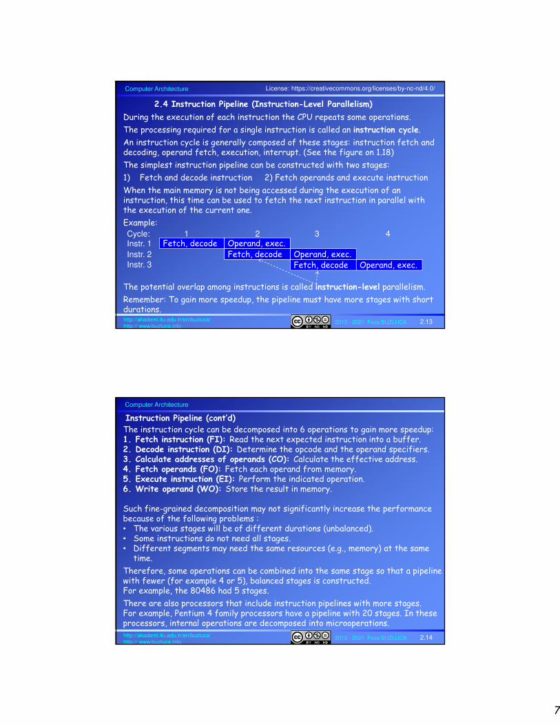
2.4 Instruction Pipeline (Instruction-Level Parallelism)
During the execution of each instruction the CPU repeats some operations.
The processing required for a single instruction is called an instruction cycle.
An instruction cycle is generally composed of these stages: instruction fetch and decoding, operand fetch, execution, interrupt. (See the figure on 1.18)
The simplest instruction pipeline can be constructed with two stages:
1) Fetch and decode instruction 2) Fetch operands and execute instruction
When the main memory is not being accessed during the execution of an instruction, this time can be used to fetch the next instruction in parallel with the execution of the current one.
Example:
The potential overlap among instructions is called instruction-level parallelism.
Remember: To gain more speedup, the pipeline must have more stages with short durations.
Fetch, decode Operand, exec.Fetch, decode Operand, exec.
Fetch, decode Operand, exec.
Instr. 1
Instr. 2
Instr. 3
Cycle: 1 2 3 4
License: https://creativecommons.org/licenses/by-nc-nd/4.0/
Computer Architecture
2013 - 2021 Feza BUZLUCA 2.14http://akademi.itu.edu.tr/en/buzluca/http:// www.buzluca.info
Instruction Pipeline (cont’d)
The instruction cycle can be decomposed into 6 operations to gain more speedup:1. Fetch instruction (FI): Read the next expected instruction into a buffer.2. Decode instruction (DI): Determine the opcode and the operand specifiers.3. Calculate addresses of operands (CO): Calculate the effective address. 4. Fetch operands (FO): Fetch each operand from memory. 5. Execute instruction (EI): Perform the indicated operation.6. Write operand (WO): Store the result in memory.
Such fine-grained decomposition may not significantly increase the performance because of the following problems :• The various stages will be of different durations (unbalanced).• Some instructions do not need all stages.• Different segments may need the same resources (e.g., memory) at the same
time.
Therefore, some operations can be combined into the same stage so that a pipeline with fewer (for example 4 or 5), balanced stages is constructed.For example, the 80486 had 5 stages.
There are also processors that include instruction pipelines with more stages.For example, Pentium 4 family processors have a pipeline with 20 stages. In these processors, internal operations are decomposed into microoperations.

8
Computer Architecture
2013 - 2021 Feza BUZLUCA 2.15http://akademi.itu.edu.tr/en/buzluca/http:// www.buzluca.info
2.4.1 An (exemplary) instruction pipeline (with 4 stages)
1. FI (Fetch Instruction): Read the next instruction the PC points to into a buffer.
2. DA (Decode, Address): Decode instruction, calculate operand addresses
3. FO (Fetch Operand): Read operands (memory/register)
4. EX (Execution): Perform the operation and update the registers (including the PC in branch/jump instructions)
• In order to perform instruction and operand fetch operations at the same time, we assume that the processor has separate instruction and data memories.
• Memory-write operations are ignored in these examples.
• This an exemplary pipelined CPU. More realistic examples are given in section "2.4.2 An Exemplary RISC Processor with Pipelining".
Computer Architecture
2013 - 2021 Feza BUZLUCA 2.16http://akademi.itu.edu.tr/en/buzluca/http:// www.buzluca.info
1
2
3
4
Instructions (Tasks)Clock cycles
1
FI
2
DA
FI
3
FO
DA
FI
FO
DA
FI
EX
4
FO
EX
EX
5 6 7The first instruction has been completed.4 cyclesThe pipeline is full.
DA FO EX
After just one cycle, the second instruction has been completed.
A) Ideal Case: No branches, no operand dependencies in the program
Timing diagram for the exemplary instruction pipeline (ideal case):
2.4.1 An (exemplary) instruction pipeline (cont'd)
The first instruction was completed in 4 cycles (k=4).
After the 4th cycle, a new instruction is completed in each cycle.
If the number of instructions approaches infinity, the completion time of an instruction approaches 1 cycle (slide 2.9 "Speedup").

9
Computer Architecture
2013 - 2021 Feza BUZLUCA 2.17http://akademi.itu.edu.tr/en/buzluca/http:// www.buzluca.info
B) Pipeline Hazards (Conflicts)
2.4.1 An (exemplary) instruction pipeline (cont'd)
B.1 Data Conflict (Operand dependency):
The operand of an instruction depends on the result of another instruction
Example :
ADD R1, R2 (R2 ← R1+R2)
SUB R2, R3 (R3 ← R2-R3)
To prevent the program from running incorrectly, a solution mechanism must be applied.
For example: The pipeline can be stopped (stall), or NOOP (No Operation)instructions can be inserted.
We will discuss possible solutions in the section "2.5 Pipeline Hazards (Conflicts) and Solutions".
InstructionsClock cycles
1
FI
2
DA
FI
3
FO
DA FO
EX
4
EX
5
Previous value (not valid) of R2 is being fetched.
R2 is updated.
Operand dependency
Computer Architecture
2013 - 2021 Feza BUZLUCA 2.18http://akademi.itu.edu.tr/en/buzluca/http:// www.buzluca.info
B.2 Control Hazards (Branches, Interrupts):
Since a pipeline processes instructions in parallel, during the processing of a branch instruction, the next instruction in the memory that should be actually skipped also enters the pipeline.
Here, a solution mechanism is necessary; otherwise, the instruction(s) that should be skipped according to the program will also be executed.
Example:
1. Instruction_12. JUMP Target 3. Instruction_3
: 4. Target Instruction_4
During the processing of the unconditional branch instruction JUMP, Instruction_3 is also fetched into the pipeline.
To prevent the program from running incorrectly, the pipeline must be stopped (stall) or emptied before Instruction_3 is executed.
Unconditional branch (or jump) instruction (BRA / JUMP)
Next instruction in the memoryAccording to the program, it should be skipped.
Target of the branch (target instruction)
2.4.1 An (exemplary) instruction pipeline (cont'd)
10
Computer Architecture
2013 - 2021 Feza BUZLUCA 2.19http://akademi.itu.edu.tr/en/buzluca/http:// www.buzluca.info
Instruction 1
Instruction 2
JUMP
Instruction 3
Target Instr. 4
InstructionsClock cycles
Steps
2
FI
3
DA
FI
FO
DA
FI
4
FO
EX
-
EX
-
FI DA
5 6 7
The new instruction after branch operation(Target of branch)
After decoding, the type of the instruction is determined: branch!
The branch address is fetched (absolute or relative).
Hazard: This instruction is fetched unnecessarily.It must not be executed.It will (must) be discarded.
Branch penalty!It is necessary to stall or emptythe pipeline.
Updating the PC (program counter)PC = Target(Target of branch)
a. Unconditional Branch
After decoding (identification) of the unconditional branch instruction, one possible solution is to stop the "Fetch Instruction" stage (FI) of the pipeline.
After the execution of the branch instruction, the target address is written to the program counter (PC), and the pipeline is enabled to fetch new instructions.
1
License: https://creativecommons.org/licenses/by-nc-nd/4.0/
Computer Architecture
2013 - 2021 Feza BUZLUCA 2.20http://akademi.itu.edu.tr/en/buzluca/http:// www.buzluca.info
Instruction 1
Conditional bra. 2
Instruction 3
InstructionsClock cycles
1
FI
2
DA
FI
3
FO
DA
FI
FO
DA
EX
4
FO
EX
EX
5 6
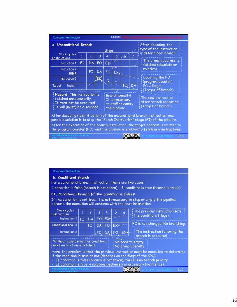
Without considering the condition,next instruction is fetched.
b. Conditional Branch:
The previous instruction sets the conditions (flags).
PC is not changed. No branching.
b1. Conditional Branch (if the condition is false):
If the condition is not true, it is not necessary to stop or empty the pipeline because the execution will continue with the next instruction.
For a conditional branch instruction, there are two cases:
1. condition is false (branch is not taken), 2. condition is true (branch is taken)
Here, the problem is that the previous instruction must be executed to determine if the condition is true or not (depends on the flags of the CPU).• If condition is false (branch is not taken), there is no branch penalty.• If condition is true, a solution mechanism is necessary (next slide).
No need to emptyNo branch penalty
The instruction following the branch is executed.
11
Computer Architecture
2013 - 2021 Feza BUZLUCA 2.21http://akademi.itu.edu.tr/en/buzluca/http:// www.buzluca.info
1
Conditional bra. 2
3
4
5
Target 6
InstructionsClock cycles
1
FI
2
DA
FI
3
FO
DA
FI
FO
DA
FI
EX
4
FO
EX
FI DA
5 6 7
The target instruction of branch
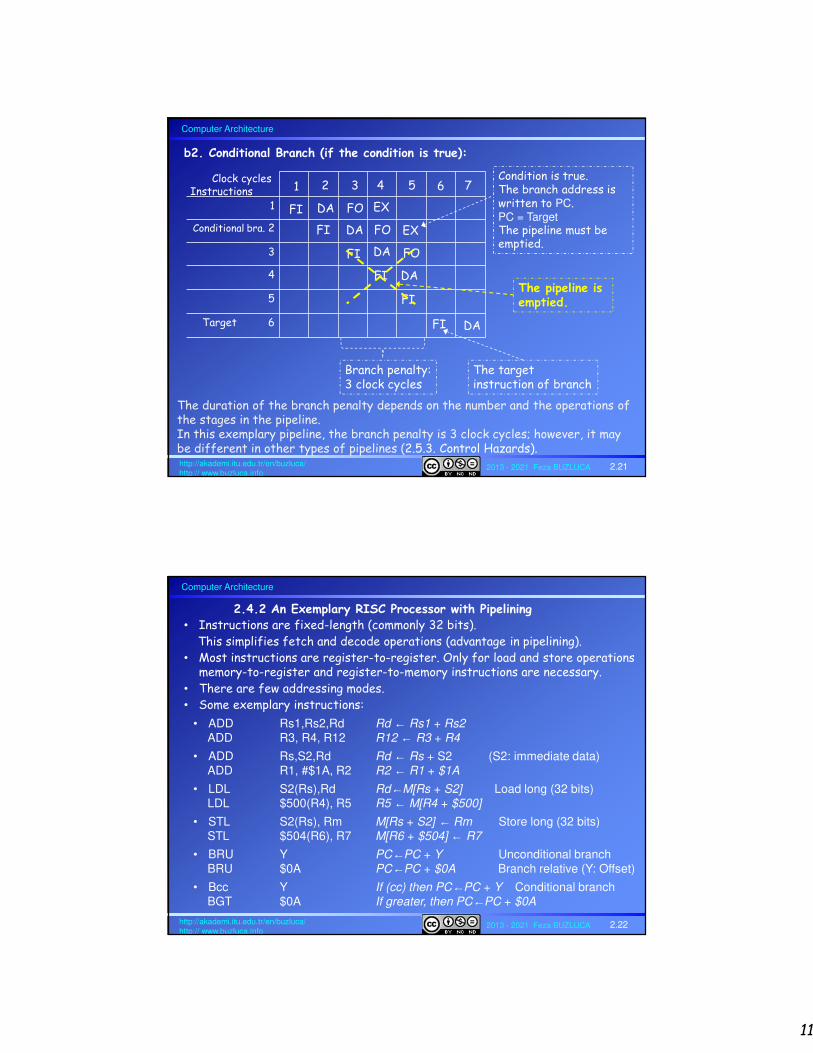
b2. Conditional Branch (if the condition is true):
DA
FIThe pipeline is emptied.
Condition is true.The branch address is written to PC.PC = TargetThe pipeline must be emptied.
Branch penalty:3 clock cycles
The duration of the branch penalty depends on the number and the operations of the stages in the pipeline.In this exemplary pipeline, the branch penalty is 3 clock cycles; however, it maybe different in other types of pipelines (2.5.3. Control Hazards).
Computer Architecture
2013 - 2021 Feza BUZLUCA 2.22http://akademi.itu.edu.tr/en/buzluca/http:// www.buzluca.info
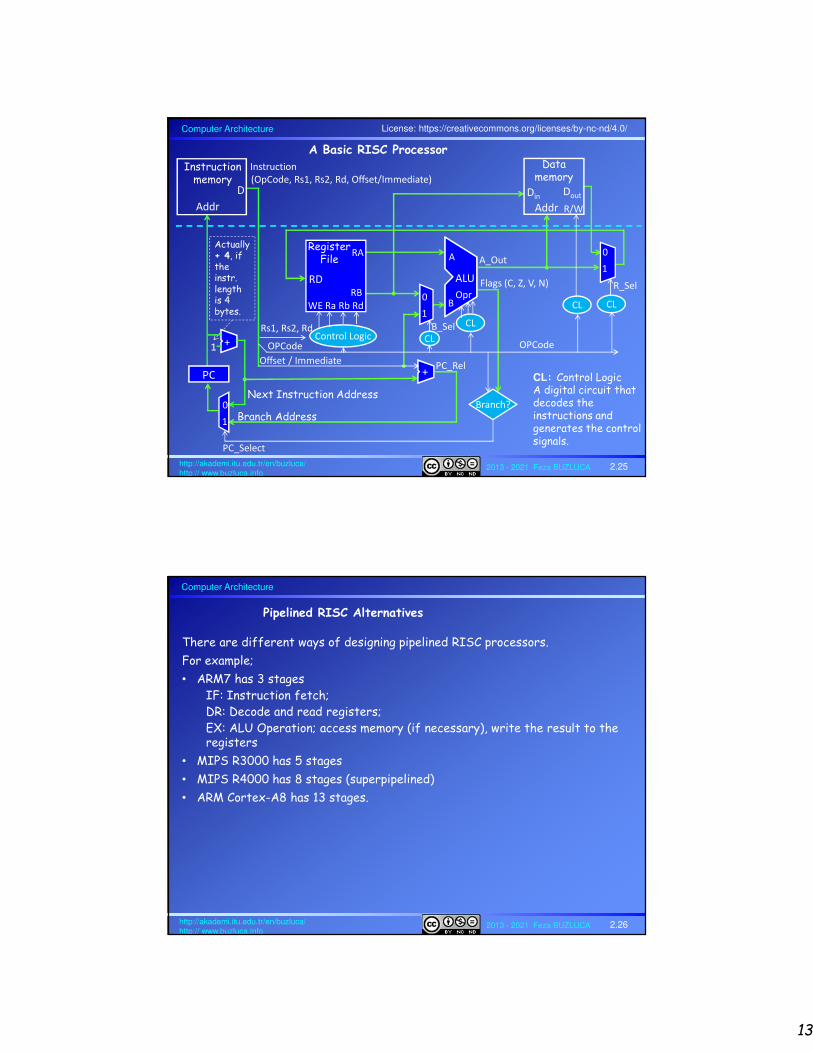
2.4.2 An Exemplary RISC Processor with Pipelining• Instructions are fixed-length (commonly 32 bits).
This simplifies fetch and decode operations (advantage in pipelining). • Most instructions are register-to-register. Only for load and store operations
memory-to-register and register-to-memory instructions are necessary.• There are few addressing modes.• Some exemplary instructions:
• ADD Rs1,Rs2,Rd Rd ← Rs1 + Rs2ADD R3, R4, R12 R12 ← R3 + R4
• ADD Rs,S2,Rd Rd ← Rs + S2 (S2: immediate data)ADD R1, #$1A, R2 R2 ← R1 + $1A
• LDL S2(Rs),Rd Rd←M[Rs + S2] Load long (32 bits)LDL $500(R4), R5 R5 ← M[R4 + $500]
• STL S2(Rs), Rm M[Rs + S2] ← Rm Store long (32 bits)STL $504(R6), R7 M[R6 + $504] ← R7
• BRU Y PC←PC + Y Unconditional branch BRU $0A PC←PC + $0A Branch relative (Y: Offset)
• Bcc Y If (cc) then PC←PC + Y Conditional branchBGT $0A If greater, then PC←PC + $0A

12
Computer Architecture
2013 - 2021 Feza BUZLUCA 2.23http://akademi.itu.edu.tr/en/buzluca/http:// www.buzluca.info
Instruction Formats of the Exemplary RISC Processor
• Three different instruction types:
1. Register mode
ADD Rs1, Rs2, Rd Rd ← Rs1 + Rs2
2. Immediate mode
• ADD Rs, S2, Rd Rd ← Rs + S2 (S2: immediate data)• LDL S2(Rs), Rd Rd←M[Rs + S2] Load long (32 bits)
Opcode Rd Rs1 0 Not used Rs2
31 26 25 21 20 16 15 14 5 4 0
6 5 5 1 10 5
Opcode Rd Rs 1 S2
31 26 25 21 20 16 15 14 0
6 5 5 1 15
Immediate data
Fixed-length: Easy to decode 32 registers
Bit number
Length
Computer Architecture
2013 - 2021 Feza BUZLUCA 2.24http://akademi.itu.edu.tr/en/buzluca/http:// www.buzluca.info
Instruction Formats of the Exemplary RISC Processor (cont'd)
3. Relative
• BRU Y PC←PC + Y Unconditional branch• Bcc Y If (cc) then PC←PC + Y Conditional branch
Opcode CC Y
31 26 25 21 20 0
6 5 21
Signed offsetCondition
CC = 0: BRU (unconditional)
13
Computer Architecture
2013 - 2021 Feza BUZLUCA 2.25http://akademi.itu.edu.tr/en/buzluca/http:// www.buzluca.info
PC
Instruction
(OpCode, Rs1, Rs2, Rd, Offset/Immediate)
CL
Branch?
PC_Select
Actually + 4, if the instr. length is 4 bytes.
1+
Next Instruction Address
+PC_Rel
Branch Address
D
Addr
Instruction memory
ALU
Opr
A
B
OPCode
A_Out
Flags (C, Z, V, N)
RA
RB
RegisterFile
WE Ra Rb Rd
RD
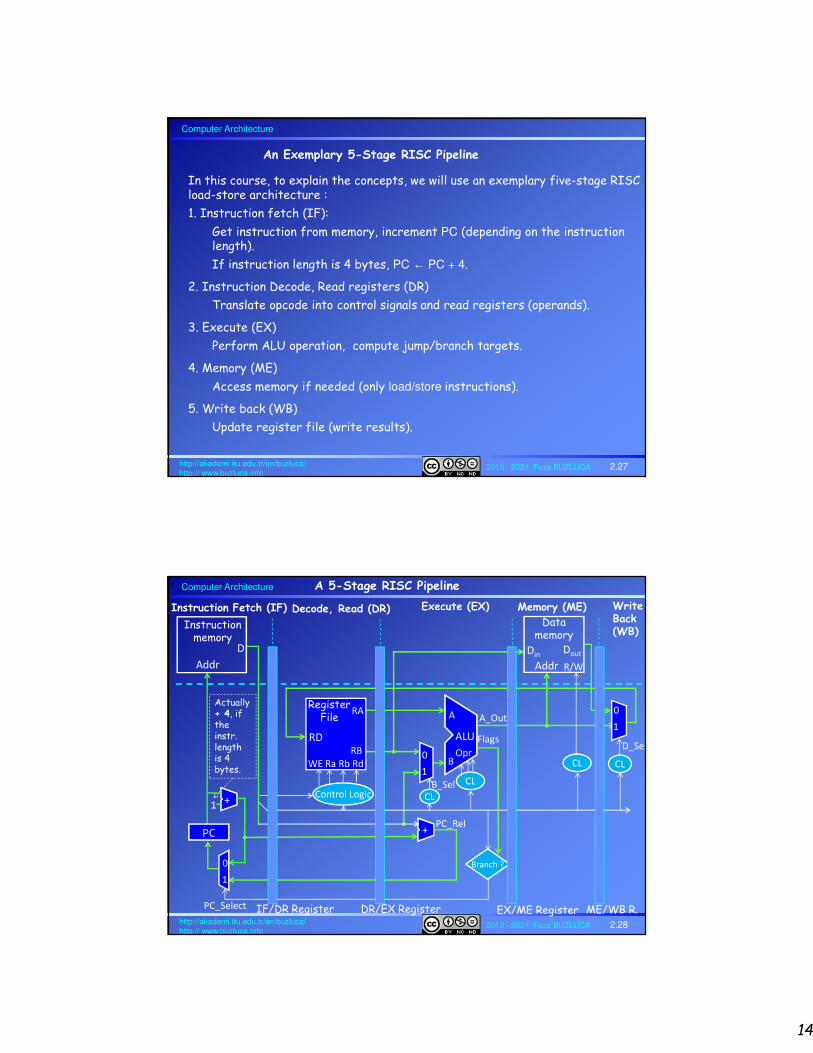
A Basic RISC Processor
Control LogicRs1, Rs2, Rd
OPCode
Offset / Immediate
CL
B_Sel
CL
R_Sel0
1
0
1
0
1
CL
Data memory
DinDout
Addr R/W
CL: Control LogicA digital circuit that decodes the instructions and generates the control signals.
License: https://creativecommons.org/licenses/by-nc-nd/4.0/
Computer Architecture
2013 - 2021 Feza BUZLUCA 2.26http://akademi.itu.edu.tr/en/buzluca/http:// www.buzluca.info
Pipelined RISC Alternatives
There are different ways of designing pipelined RISC processors.
For example;
• ARM7 has 3 stagesIF: Instruction fetch;DR: Decode and read registers;EX: ALU Operation; access memory (if necessary), write the result to the registers
• MIPS R3000 has 5 stages
• MIPS R4000 has 8 stages (superpipelined)
• ARM Cortex-A8 has 13 stages.
14
Computer Architecture
2013 - 2021 Feza BUZLUCA 2.27http://akademi.itu.edu.tr/en/buzluca/http:// www.buzluca.info
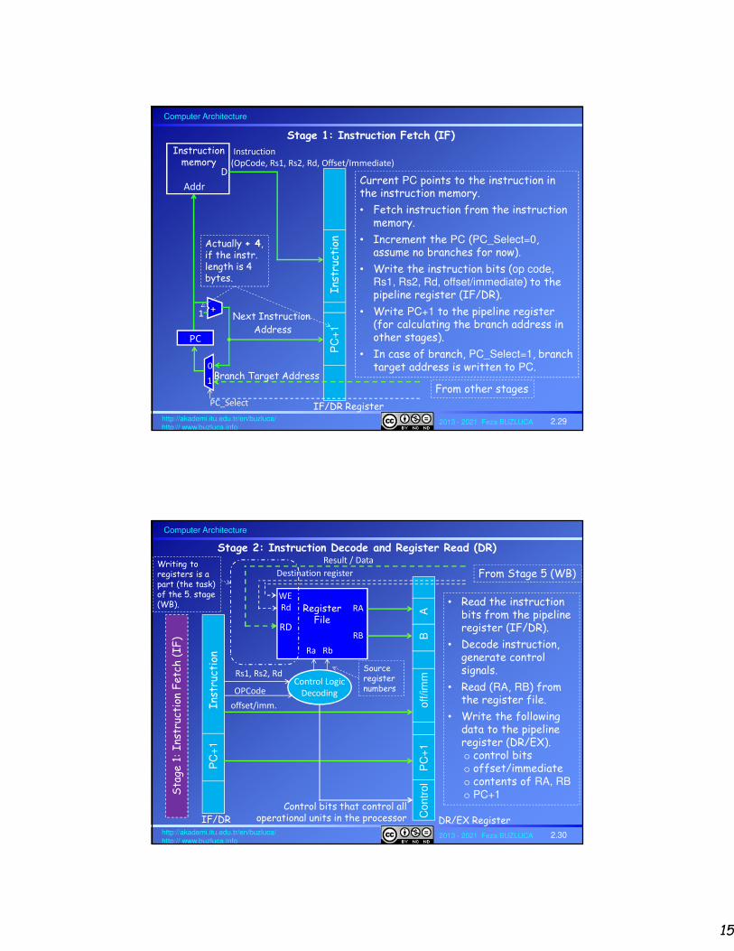
In this course, to explain the concepts, we will use an exemplary five-stage RISC load-store architecture :
1. Instruction fetch (IF):
Get instruction from memory, increment PC (depending on the instruction length).
If instruction length is 4 bytes, PC ← PC + 4.
2. Instruction Decode, Read registers (DR)
Translate opcode into control signals and read registers (operands).
3. Execute (EX)
Perform ALU operation, compute jump/branch targets.
4. Memory (ME)
Access memory if needed (only load/store instructions).
5. Write back (WB)
Update register file (write results).
An Exemplary 5-Stage RISC Pipeline
Computer Architecture
2013 - 2021 Feza BUZLUCA 2.28http://akademi.itu.edu.tr/en/buzluca/http:// www.buzluca.info
A 5-Stage RISC Pipeline
PC
CL
Branch ?
PC_Select
Actually + 4, if the instr. length is 4 bytes.
1+
+PC_Rel
D
Addr
Instruction memory
ALU
Opr
A
B
A_Out
Flags
RA
RB
RegisterFile
WE Ra Rb Rd
RD
Control Logic CL
B_Sel
CL
D_Sel0
1
0
1
0
1
CL
Data memory
DinDout
Addr R/W
Instruction Fetch (IF) Decode, Read (DR) Execute (EX) Memory (ME) Write Back (WB)
IF/DR Register DR/EX Register EX/ME Register ME/WB R.
15
Computer Architecture
2013 - 2021 Feza BUZLUCA 2.29http://akademi.itu.edu.tr/en/buzluca/http:// www.buzluca.info
PC
+1
Inst
ruct
ion
IF/DR Register
Stage 1: Instruction Fetch (IF)
PC
1+
Next Instruction Address
D
Addr
Instruction memory
0
1
Instruction
(OpCode, Rs1, Rs2, Rd, Offset/Immediate)
PC_Select
Branch Target Address
From other stages
Actually + 4, if the instr. length is 4 bytes.
Current PC points to the instruction in the instruction memory.
• Fetch instruction from the instruction memory.
• Increment the PC (PC_Select=0, assume no branches for now).
• Write the instruction bits (op code, Rs1, Rs2, Rd, offset/immediate) to the pipeline register (IF/DR).
• Write PC+1 to the pipeline register (for calculating the branch address in other stages).
• In case of branch, PC_Select=1, branch target address is written to PC.
Computer Architecture
2013 - 2021 Feza BUZLUCA 2.30http://akademi.itu.edu.tr/en/buzluca/http:// www.buzluca.info
Stage 2: Instruction Decode and Register Read (DR)
RA
RB
RegisterFile
Ra Rb
RD
WE
Rd
Control Logic
Decoding
Rs1, Rs2, Rd
OPCode
PC
+1
I
nstr
ucti
on
Co
ntr
ol
P
C+
1
o
ff/im
mB
A
offset/imm.
Control bits that control all operational units in the processor
Result / Data
Destination register From Stage 5 (WB)
Sta
ge 1
: In
stru
ctio
n F
etch
(IF
)
• Read the instruction bits from the pipeline register (IF/DR).
• Decode instruction, generate control signals.
• Read (RA, RB) from the register file.
• Write the following data to the pipeline register (DR/EX).o control bits o offset/immediateo contents of RA, RBo PC+1
DR/EX RegisterIF/DR
Writing to registers is a part (the task) of the 5. stage (WB).
Source register numbers

16
Computer Architecture
2013 - 2021 Feza BUZLUCA 2.31http://akademi.itu.edu.tr/en/buzluca/http:// www.buzluca.info
Stage 3: Execute (EX)
• Read the control bits and data (offset/immediate, RA, RB) from the pipeline register (DR/EX).
• Perform the ALU operation.The ALU also calculates memory addresses for LOAD/STORE instructions.For example; LDL $500(R4), R5 R5 ← M[R4 + $500]
The immediate value $500 is added to the contents of R4 in the ALU.
• Compute target addresses for the branch instructionsFor example: BGT $0A If greater, then PC←PC + $0A
In this exemplary processor, an additional adder is used for target address calculation.
• Decide if the jump/branch should be taken (control bits and flags from the ALU are used)
• Write the following data to the pipeline register (EX/ME):o Control bits o Result of the ALU (D) and flags (F)o RB for memory store operations (B)o Branch target address
License: https://creativecommons.org/licenses/by-nc-nd/4.0/
Computer Architecture
2013 - 2021 Feza BUZLUCA 2.32http://akademi.itu.edu.tr/en/buzluca/http:// www.buzluca.info
Stage 3: Execute (EX)
Sta
ge 2
: In
stru
ctio
n D
ecod
e an
d R
egis
ter
Rea
d (
DR
)
Co
ntr
ol
P
C+
1
o
ff/im
mB
A
ALU
Opr
A
B
A_Out
Flags
0
1
B_Select
ALU
Operation
+, -, shift, …
Co
ntr
ol
Ta
rge
t
B
F
D
Flags (C, Z, V, N)
Branch?
PC_Select
+
Relative branch address calculation
Branch Address
Branch Address
To Stage 1
To DataMemory
DR/EXEX/ME

17
Computer Architecture
2013 - 2021 Feza BUZLUCA 2.33http://akademi.itu.edu.tr/en/buzluca/http:// www.buzluca.info
Data memory
Din
Dout
Address
R/W CS
Stage 4: Memory (ME)
Sta
ge 3
: E
xec
ute
(EX
)
To Stage 1
• Read address (result of the ALU) D from the pipeline register (EX/ME).
• Read data B (for STORE) from the pipeline register.
• Perform memory load/store if needed.
• Write the following data to the pipeline register (ME/WB).o Control bits o Result of memory
operation (M)o Result of ALU
operation (D) (pass)
Co
ntr
ol
Ta
rge
t
B
F
D
EX/ME Register
Co
ntr
ol
M
D
ME/WB Register
Computer Architecture
2013 - 2021 Feza BUZLUCA 2.34http://akademi.itu.edu.tr/en/buzluca/http:// www.buzluca.info
Stage 5: Write Back (WB)
Sta
ge 4
: M
emor
y (M
E)
Co
ntr
ol
M
D
Data_Select
To Register File
0
1
Result/Data
To Register FileDestination register Rd
WE
(Write
enable)
• Read result of the ALU (D) from the pipeline register (ME/WB).
• Read the result of the memory operation (M) from the pipeline register (ME/WB).
• Select value (D or M) and write to register file.
• Send control information (Rd, WE) to register file.
• Write to register file.
• Stage 2 reads the register file, stage 5 writes to it.
ME/WB Register
Writing to registers is a part (the task) of the 5. stage (WB).(Slide 2.30)

18
Computer Architecture
2013 - 2021 Feza BUZLUCA 2.35http://akademi.itu.edu.tr/en/buzluca/http:// www.buzluca.info
1
2
3
4
Instructions Clock cycles
1
IF
2
DR
IF
3
EX
DR
IF
EX
DR
ME
4
EX
ME
ME
5 6 7The first instruction has been completed.5 cyclesPipeline is full.
Just after one cycle, the second instruction has been completed.
Ideal Case: No branches, no conflicts
Timing diagram for the exemplary RISC pipeline (ideal case):
The first instruction was completed in 5 cycles (k = 5).
After the 5th cycle, a new instruction is completed in each cycle.
If the number of instructions approaches infinity, the completion time of an instruction approaches 1 cycle (see slide 2.9 "Speedup").
WB
WB
WB
8
IF DR EX ME WB
IF and ME stages try to access the memory at the same time.
To solve the resource conflict problem, separate memories for instruction and data are used (Harvard architecture).
Computer Architecture
2013 - 2021 Feza BUZLUCA 2.36http://akademi.itu.edu.tr/en/buzluca/http:// www.buzluca.info
2.5 Pipeline Hazards (Conflicts) and Solutions
There are three types of hazards
1. Resource Conflict (Structural hazard):
A resource hazard occurs when two (or more) instructions that are already in the pipeline need the same resource (memory, functional unit).
2. Data Conflict (Hazard)
Data hazards occur when data is used before it is ready.
3. Control Hazards (Branch, Jump, Interrupt):
During the processing of a branch instruction, the next instruction in the memory that should actually be skipped also enters the pipeline.
Which target instruction should be fetched into the pipeline is unknown, unless the CPU executes the branch instruction (updating the PC).
Conditional branch problem: Until the actual execution of the instruction that alters the flag values, the flag values are unknown (greater?, equal?), so it is impossible to determine if the branch will be taken.
Stalling solves all these conflicts but it reduces the performance of the system.
There are more efficient solutions.

19
Computer Architecture
2013 - 2021 Feza BUZLUCA 2.37http://akademi.itu.edu.tr/en/buzluca/http:// www.buzluca.info
A resource hazard occurs when two (or more) instructions that are already in the pipeline need the same resource (memory, functional unit).
a) Memory conflict: "An operand read to or write from memory cannot be performed in parallel with an instruction fetch."
Solutions:
• Instructions must be executed serially rather than in parallel for a portion of the pipeline (stall). (Performance drops.)
• Harvard architecture: Separate memories for instructions and data.
• Instruction queue or cache memory: There are times during the execution of an instruction when main memory is not being accessed. This time could be used to prefetch the next instruction and write it to a queue (instruction buffer).
b) Functional unit (ALU, FPU) conflict.Solutions:• Increasing available functional units and using multiple ALUs.For example, different ALUs can be used address calculation and data operations.• Fully pipelining a functional unit (for example, a floating point unit FPU)
2.5.1. Resource Conflict (Structural hazard):
License: https://creativecommons.org/licenses/by-nc-nd/4.0/
Computer Architecture
2013 - 2021 Feza BUZLUCA 2.38http://akademi.itu.edu.tr/en/buzluca/http:// www.buzluca.info
Data hazards occur when data is used before it is ready.
If the problem is not solved, the program may produce an incorrect result because of the use of pipelining.
Example:
2.5.2. Data Conflict (Hazard):
ADD R1,R2,R3
SUB R3,R4,R5
1
IF
2
DR
IF
3
EX
DR EX
4 5 6
Data dependency in the pipeline
Clock cyclesInstructions
ME WB
ME WB
ADD R1, R2, R3 R3 ← R1 + R2
SUB R3, R4, R5 R5 ← R3 – R4 Result of ADD is written to the register file (R3).
SUB reads R3 before it has been updated.R3 does not contain the result of the previous ADD instruction; it has not been processed in WB yet.

20
Computer Architecture
2013 - 2021 Feza BUZLUCA 2.39http://akademi.itu.edu.tr/en/buzluca/http:// www.buzluca.info
There are three types of data hazards:
• Read after write (RAW), or true dependency: An instruction modifies a register or memory location, and a succeeding instruction reads the data in that memory or register location.
A hazard occurs if the read takes place before the write operation is complete.
• Write after read (WAR), or antidependency: An instruction reads a register or memory location, and a succeeding instruction writes to the location.
A hazard occurs if the write operation completes before the read operation takes place.
• Write after write (WAW), or output dependency: Two instructions both write to the same location.
A hazard occurs if the write operations take place in the reverse order of the intended sequence.
2.5.2. Data Conflict (cont’d):
Computer Architecture
2013 - 2021 Feza BUZLUCA 2.40http://akademi.itu.edu.tr/en/buzluca/http:// www.buzluca.info
Solutions to Data Hazards:
A) Stalling, Hardware interlock (Hardware-based solution):
An additional hardware unit tracks all instructions (control bits) in the pipeline registers and stops (stalls) the instruction fetch (IF) stage of the pipeline when a hazard is detected.
The instruction that causes the hazard is delayed (not fetched) until the conflict is solved.
Example:
ADD R1,R2,R3
SUB R3,R4,R5
1
IF
2
DR
3
EX
4 5 6Clock cycles
Instructions
ME WB
First write to R3, then read it.Write and read in different clock cycles.
IF DR EX ME WB
7 8 9
- - -
Data conflict is detected.IF/DR.Rs1 == DR/EX.Rd
Pipeline is stalled.3-clock-cycles delay
Stalling the pipeline:
• IF/DR register is disabled (no update).
• Control bits of the NOOP (No Operation) instruction are inserted into the DR stage.
• The PC is not updated.

21
Computer Architecture
2013 - 2021 Feza BUZLUCA 2.41http://akademi.itu.edu.tr/en/buzluca/http:// www.buzluca.info
Fixing the register file access hazard:
The register file can be accessed in the same cycle for reading and writing.
Data can be written in the first half of the cycle (rising edge) and read in the second half (falling edge).
This method reduces the waiting (stalling) time from 3 cycles to 2 cycles.
Solutions to Data Hazards (cont'd):
First write to R3in the first half, then read it in the second half.
Write Read
1
IF
2
DR
3
EX
4 5 6Clock cyclesInstructions
ME WB
IF DR EX ME WB
7 8
- -
ADD R1,R2,R3
SUB R3,R4,R5
Data conflict is detected.IF/DR.Rs1 == DR/EX.Rd
Computer Architecture
2013 - 2021 Feza BUZLUCA 2.42http://akademi.itu.edu.tr/en/buzluca/http:// www.buzluca.info
Solutions to Data Hazards (cont'd):
B) Operand forwarding (Bypassing) (Hardware-based):
An optional direct connection is established between the output of the EX stage (EX/ME register) and the inputs of the ALU.
Stage 3: Execute (EX)Sta
ge 2
: D
ecod
e R
ead (
DR
)
B_Select
ALU
Opr
A
B
A_Out
Flags
ALU
Operation
+, -, shift, …
0
1
A_Select
Forwarding (Bypass)
A_Select and B_Select are controlled by the hazard detection unit of the pipeline. It selects either the value from the register file or the forwarded result (bypass) as the ALU input.
off/im
mB
A
DR/EX
B
F
D
EX/ME

22
Computer Architecture
2013 - 2021 Feza BUZLUCA 2.43http://akademi.itu.edu.tr/en/buzluca/http:// www.buzluca.info
Operand forwarding (Bypassing) from EX/ME to ALU (cont'd):
If the hazard unit detects that the destination of the previous ALU operation is the same register as the source of the current ALU operation, the control logic selects the forwarded result (bypass) as the ALU input, rather than the value from the register.
Example:
ADD R1, R2, R3; R3←R1 + R2
SUB R3, R4, R5; R5←R3 - R4
InstructionsClock cycles
1
IF
2
DR
IF
3
EX
DR EX
ME
4
ME
5
Previous value (not valid) of R3 is fetched.This invalid value will not be used in the EX cycle.
The control unit of the pipeline selects the output of the previous ALU operation (bypass) as the input, not the value that has been read in the DR stage (A_Select = 0).
If it is possible to solve the register conflict by forwarding, it is not necessary to stall the pipeline.
The performance does not drop.
WB
License: https://creativecommons.org/licenses/by-nc-nd/4.0/
Computer Architecture
2013 - 2021 Feza BUZLUCA 2.44http://akademi.itu.edu.tr/en/buzluca/http:// www.buzluca.info
Solution to load-use data hazard using Operand forwarding (Bypassing)
Load-use data hazard:
Load instructions may also cause data hazards.
Example:
1
IF
2
DR
IF
3
EX
DR EX
4 5 6Clock cycles
Instructions
ME WB
ME WB
LDL $500(R4), R1 R1 ← M[R4 + $500]
ADD R1, R2, R3 R3 ← R1 + R2
Data from memory is written to the register file (R1).
ADD reads R1 before it has been updated.The value in R1 is not valid.
Load-use data hazard

23
Computer Architecture
2013 - 2021 Feza BUZLUCA 2.45http://akademi.itu.edu.tr/en/buzluca/http:// www.buzluca.info
Forwarding (Bypass)From EX/ME to ALU
Forwarding (Bypass)From ME/WB to ALU
Operand forwarding (Bypassing) from ME/WB to ALU:
To decrease the waiting time caused by load-use hazard, an optional direct connection can be established between the output of the ME stage (ME/WB register) and the inputs of the ALU.
However, one clock cycle delay is still needed.
Data memory
Din
Dout
Address
R/W CS
M
D
To Register File
ME/WB
ALU
Opr
A
B
A_Out
Flags
B_Select
ALU
Operation
+, -, shift, …
B
F
D
OperandSelect
EX/ME
off/im
mB
A
DR/EX
Computer Architecture
2013 - 2021 Feza BUZLUCA 2.46http://akademi.itu.edu.tr/en/buzluca/http:// www.buzluca.info
Solution with forwarding + 1 cycle stalling
Example:
Solution with forwarding (+stalling)
Load_use data hazard (cont'd):
The previous value (not valid) of R1 is fetched.This invalid value will not be used in the EX cycle.
The control unit of the pipeline selects the forwarding path as the input, not the value that has been read in the DR stage.
1
IF
2
DR
IF
3
EX
DR EX
4 5 6Clock cycles
Instructions
ME WB
ME WB
LDL $500(R4), R1
ADD R1, R2, R3
7
-
24
Computer Architecture
2013 - 2021 Feza BUZLUCA 2.47http://akademi.itu.edu.tr/en/buzluca/http:// www.buzluca.info
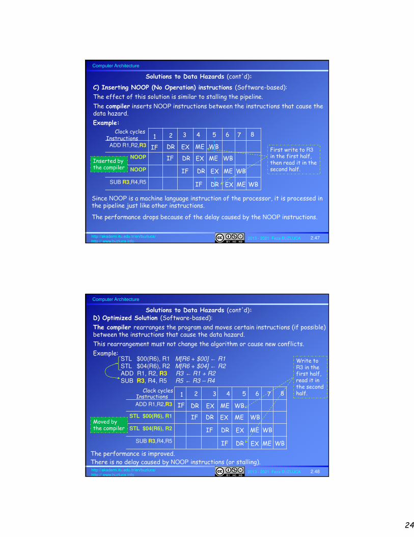
Solutions to Data Hazards (cont'd):
C) Inserting NOOP (No Operation) instructions (Software-based):
The effect of this solution is similar to stalling the pipeline.
The compiler inserts NOOP instructions between the instructions that cause thedata hazard.
Example:
ADD R1,R2,R3
NOOP
NOOP
SUB R3,R4,R5
1
IF
2
DR
3
EX
4 5 6Clock cyclesInstructions
ME WB First write to R3in the first half, then read it in the second half.
IF DR EX ME WB
7 8
Inserted by the compiler
IF DR EX ME WB
IF DR EX ME WB
Since NOOP is a machine language instruction of the processor, it is processed in the pipeline just like other instructions.
The performance drops because of the delay caused by the NOOP instructions.
Computer Architecture
2013 - 2021 Feza BUZLUCA 2.48http://akademi.itu.edu.tr/en/buzluca/http:// www.buzluca.info
Solutions to Data Hazards (cont'd):D) Optimized Solution (Software-based):
The compiler rearranges the program and moves certain instructions (if possible) between the instructions that cause the data hazard.
This rearrangement must not change the algorithm or cause new conflicts.
Example:STL $00(R6), R1 M[R6 + $00] ← R1STL $04(R6), R2 M[R6 + $04] ← R2ADD R1, R2, R3 R3 ← R1 + R2SUB R3, R4, R5 R5 ← R3 – R4
ADD R1,R2,R3
STL $00(R6), R1
STL $04(R6), R2
SUB R3,R4,R5
1
IF
2
DR
3
EX
4 5 6Clock cyclesInstructions
ME WB
Write to R3 in the first half, read it in the second half.
IF DR EX ME WB
7 8
IF DR EX ME WB
IF DR EX ME WB
Moved by the compiler
The performance is improved.There is no delay caused by NOOP instructions (or stalling).

25
Computer Architecture
2013 - 2021 Feza BUZLUCA 2.49http://akademi.itu.edu.tr/en/buzluca/http:// www.buzluca.info
2.5.3. Control Hazards (Branches, Interrupts):
In the exemplary RISC processor, the following operations are performed for the branch/jump instructions:
• The target address for the branch (jump) instruction is calculated in the Execution (EX) stage (slide 2.32).
• The target address is written to the EX/ME pipeline register.
• The branch decision is made in the Memory (ME) stage based on the values of flags that are determined after the execution in the EX stage (slide 2.32).
• After the EX stage, the result of the decision (PC_Select) and the target address are sent to Stage 1 (IF).
• In the IF stage, the next instruction the PC points to is fetched first, then the PC is updated (slide 2.29).
During these operations, the next instructions in sequence (not the target of branch) are fetched into the pipeline.
However, if the branch is taken, these instructions should be skipped.
In this case, either a hardware unit must empty the pipeline, or compiler-based solutions (delayed branch) must be applied.
The unnecessary instructions must be stopped before they are processed in the WB stage because the registers of the CPU are changed in that stage.
License: https://creativecommons.org/licenses/by-nc-nd/4.0/
Computer Architecture
2013 - 2021 Feza BUZLUCA 2.50http://akademi.itu.edu.tr/en/buzluca/http:// www.buzluca.info
Conditional Branch Hazards:
Example:
100 SUB R1, R2, R1 R1 ← R1 - R2104 BGT $1C Branch if greater ($108 + $1C = $124 Target address)108 ADD R1, R1, R210C ADD R3, R4, R2110 STL $00(R5), R2114 LDL $0A(R6), R1…124 STL $00(R6), R2 Target of BGT ----------------------------------------------------------------------------------------------
These instructions should be skipped if the branch is taken.
Remember: Bcc conditional branch instructions check the flag values generated by the last ALU operation.
For example, the BGT instruction (signed comparison) checks the flags N(Negative), V (Overflow), and Z (Zero).
Overflow (V) Sign (N) Zero (Z) Comparison
X (not important) Positive (0) YES (1) A=B
NO (0) Positive (0) NO (0) A>B
NO (0) Negative (1) NO (0) A<B
YES (1) Positive (0) NO (0) A<B
YES (1) Negative (1) NO (0) A>B
After the operation
R = A – B
the table on the right is used to compare the signed integers.
26
Computer Architecture
2013 - 2021 Feza BUZLUCA 2.51http://akademi.itu.edu.tr/en/buzluca/http:// www.buzluca.info
Instructions
SUB R1, R2, R1 IF
BGT $1C
DR EX ME WB
IF DR EX ME WB
ADD R1, R1, R2
ADD R3, R4, R2
IF DR EX ME WB
IF DR EX ME WB
STL $00(R5), R2 IF DR EX ME WB
Target: STL $00(R6), R2 IF DR EX ME WB
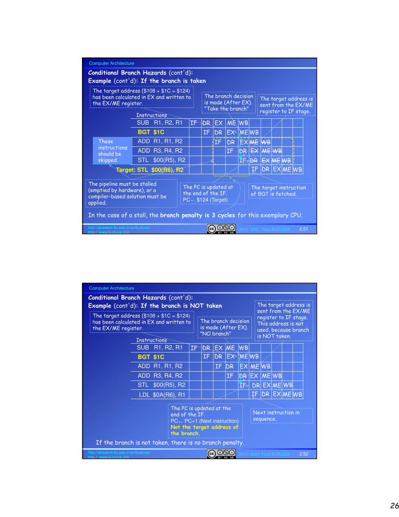
The target address ($108 + $1C = $124) has been calculated in EX and written to the EX/ME register.
The target address is sent from the EX/ME register to IF stage.
Conditional Branch Hazards (cont'd):
Example (cont'd): If the branch is taken
The PC is updated at the end of the IF.PC← $124 (Target)
The target instruction of BGT is fetched.
These instructions should be skipped.
The pipeline must be stalled (emptied by hardware), or a compiler-based solution must be applied.
In the case of a stall, the branch penalty is 3 cycles for this exemplary CPU.
The branch decision is made (After EX). "Take the branch"
Computer Architecture
2013 - 2021 Feza BUZLUCA 2.52http://akademi.itu.edu.tr/en/buzluca/http:// www.buzluca.info
Instructions
SUB R1, R2, R1 IF
BGT $1C
DR EX ME WB
IF DR EX ME WB
ADD R1, R1, R2
ADD R3, R4, R2
IF DR EX ME WB
IF DR EX ME WB
STL $00(R5), R2 IF DR EX ME WB
LDL $0A(R6), R1 IF DR EX ME WB
The target address ($108 + $1C = $124) has been calculated in EX and written to the EX/ME register.
The target address is sent from the EX/ME register to IF stage.This address is not used, because branch is NOT taken.
Conditional Branch Hazards (cont'd):
Example (cont'd): If the branch is NOT taken
The PC is updated at the end of the IF.PC← PC+1 (Next instruction)Not the target address of the branch.
Next instruction in sequence.
If the branch is not taken, there is no branch penalty.
The branch decision is made (After EX). "NO branch"

27
Computer Architecture
2013 - 2021 Feza BUZLUCA 2.53http://akademi.itu.edu.tr/en/buzluca/http:// www.buzluca.info
Reducing the branch penalty:
Branch target address calculation and decision operations are performed in the EX stage, and results are sent directly to the IF stage.
In the case of a stall, we will have 2 cycles (instead of 3) of branch penalty, if the branch is taken (slide 2.54).
The decision operation will increase the delay of the EX stage.
PC
+1
off/im
mB
A
B
F
D
ALU
Opr
A
B
A_Out
Flags
0
1
PC_Select
Branch?+
Relative branch address calculation
Branch Target
Address
To Stage 1 (IF)
Conditional branch:
The Execute (EX) stage is modified. Execute (EX) stage
Computer Architecture
2013 - 2021 Feza BUZLUCA 2.54http://akademi.itu.edu.tr/en/buzluca/http:// www.buzluca.info
Reducing the branch penalty (cont'd):
Conditional branch (cont'd) : If branch is taken
Example:
Instructions
SUB R1, R2, R1 IF
BGT $1C
DR EX ME WB
IF DR EX ME WB
ADD R1, R1, R2
ADD R3, R4, R2
IF DR EX ME WB
IF DR EX ME WB
IF DR EX ME WBTarget: STL $00(R6), R2
The target address ($108 + $1C = $124) has been calculated.The branch decision has been made (In EX).
The target address is sent to the IF stage.
The PC is updated at the end of the IF.PC← $124 (Target)
The target instruction of BGT is fetched.
These instructions should be skipped.
The pipeline must be stalled (emptied by hardware), or a compiler-based solution must be applied.
In the case of a stall, the branch penalty is 2 cycles for this exemplary pipeline.
28
Computer Architecture
2013 - 2021 Feza BUZLUCA 2.55http://akademi.itu.edu.tr/en/buzluca/http:// www.buzluca.info
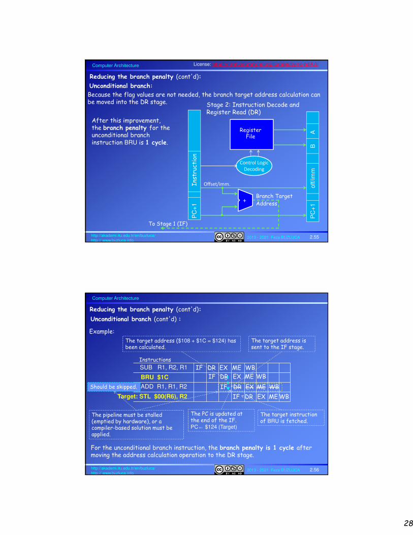
Reducing the branch penalty (cont'd):
Unconditional branch:
Because the flag values are not needed, the branch target address calculation can be moved into the DR stage.
RegisterFile
Control Logic
Decoding
PC
+1
In
stru
ctio
n
PC
+1
off/im
mB
A
Offset/imm.
+Branch Target Address
To Stage 1 (IF)
Stage 2: Instruction Decode and Register Read (DR)
After this improvement, the branch penalty for theunconditional branch instruction BRU is 1 cycle.
License: https://creativecommons.org/licenses/by-nc-nd/4.0/
Computer Architecture
2013 - 2021 Feza BUZLUCA 2.56http://akademi.itu.edu.tr/en/buzluca/http:// www.buzluca.info
Reducing the branch penalty (cont'd):
Unconditional branch (cont'd) :
Example:
Instructions
SUB R1, R2, R1 IF
BRU $1C
DR EX ME WB
IF DR EX ME WB
ADD R1, R1, R2 IF DR EX ME WB
IF DR EX ME WBTarget: STL $00(R6), R2
The target address ($108 + $1C = $124) has been calculated.
The target address is sent to the IF stage.
The PC is updated at the end of the IF.PC← $124 (Target)
The target instruction of BRU is fetched.
Should be skipped.
The pipeline must be stalled (emptied by hardware), or a compiler-based solution must be applied.
For the unconditional branch instruction, the branch penalty is 1 cycle after moving the address calculation operation to the DR stage.
29
Computer Architecture
2013 - 2021 Feza BUZLUCA 2.57http://akademi.itu.edu.tr/en/buzluca/http:// www.buzluca.info
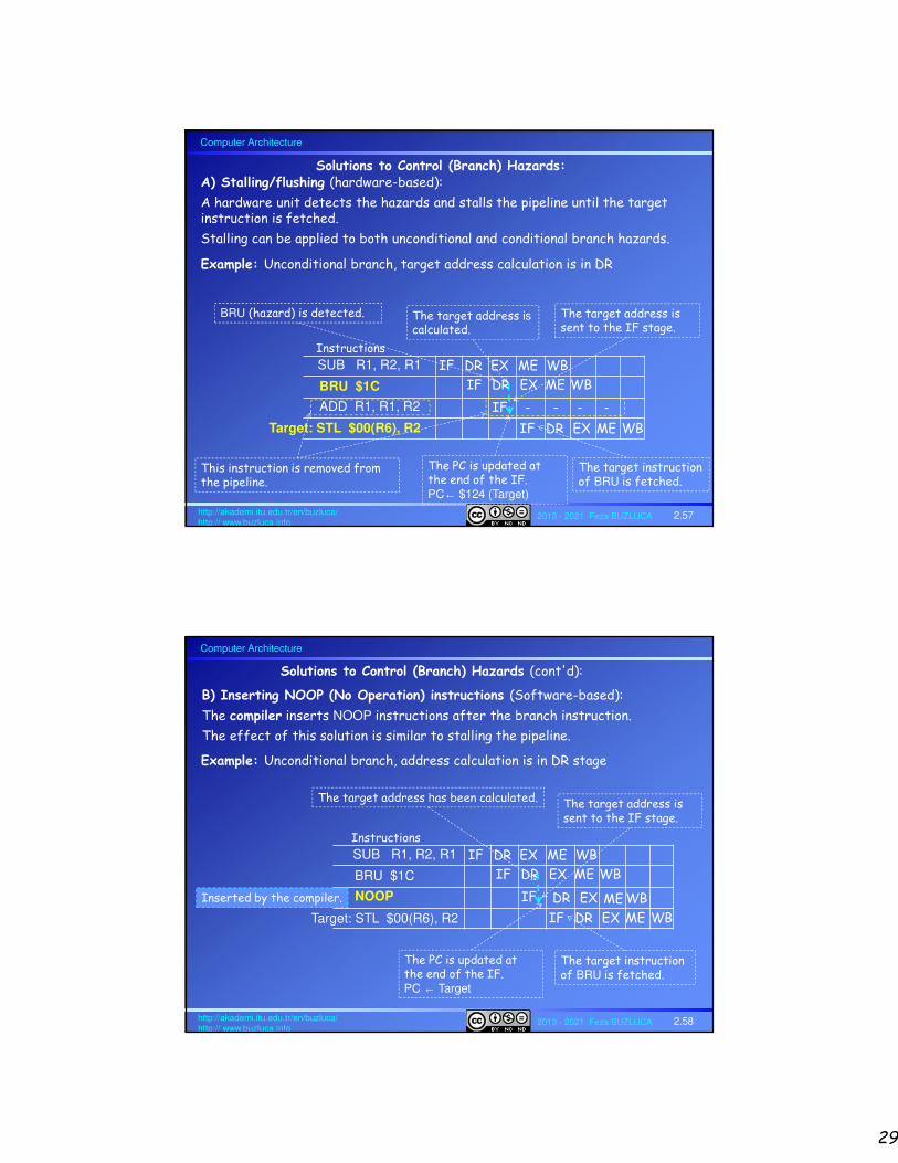
Solutions to Control (Branch) Hazards:A) Stalling/flushing (hardware-based):
A hardware unit detects the hazards and stalls the pipeline until the target instruction is fetched.
Stalling can be applied to both unconditional and conditional branch hazards.
Example: Unconditional branch, target address calculation is in DR
Instructions
SUB R1, R2, R1 IF
BRU $1C
DR EX ME WB
IF DR EX ME WB
ADD R1, R1, R2 IF - - - -
IF DR EX ME WBTarget: STL $00(R6), R2
The target address iscalculated.
The target address is sent to the IF stage.
The PC is updated at the end of the IF.PC← $124 (Target)
The target instruction of BRU is fetched.
BRU (hazard) is detected.
This instruction is removed from the pipeline.
Computer Architecture
2013 - 2021 Feza BUZLUCA 2.58http://akademi.itu.edu.tr/en/buzluca/http:// www.buzluca.info
Solutions to Control (Branch) Hazards (cont'd):
B) Inserting NOOP (No Operation) instructions (Software-based):
The compiler inserts NOOP instructions after the branch instruction.
The effect of this solution is similar to stalling the pipeline.
Example: Unconditional branch, address calculation is in DR stage
Instructions
SUB R1, R2, R1 IF
BRU $1C
DR EX ME WB
IF DR EX ME WB
NOOP IF EX ME WB
IF DR EX ME WBTarget: STL $00(R6), R2
The target address has been calculated. The target address is sent to the IF stage.
The PC is updated at the end of the IF.PC ← Target
The target instruction of BRU is fetched.
DRInserted by the compiler.

30
Computer Architecture
2013 - 2021 Feza BUZLUCA 2.59http://akademi.itu.edu.tr/en/buzluca/http:// www.buzluca.info
The number of NOOP instructions that need to be inserted depend on the number of stall cycles required.
Example: Conditional branch;address calculation and branch decisions are in EX (slide 2.53).
In this case, 2 stall cycles are necessary. Therefore, 2 NOOPs are inserted.
B) Inserting NOOP (No Operation) instructions (cont'd):
Instructions
SUB R1, R2, R1 IF
BGT $1C
DR EX ME WB
IF DR EX ME WB
NOOP
NOOP
IF DR EX ME WB
IF DR EX ME WB
IF DR EX ME WBTarget: STL $00(R6), R2
The target address ($108 + $1C = $124) has been calculated.The branch decision has been made (In EX).
The target address is sent to the IF stage.
The PC is updated at the end of the IF. PC ← Target
The target instruction of BGT is fetched.
Inserted by the compiler.
Computer Architecture
2013 - 2021 Feza BUZLUCA 2.60http://akademi.itu.edu.tr/en/buzluca/http:// www.buzluca.info
C) Optimized Solution (Software-based):
The compiler rearranges the program and moves certain instructions (if possible) to immediately after the branch instruction.
This rearrangement must not change the algorithm or cause new conflicts.
Solutions to Control (Branch) Hazards (cont'd):
Example: Unconditional branch, address calculation is in DR stage
Instructions
BRU $1C IF DR EX ME WB
IF EX ME WB
IF DR EX ME WBTarget: STL $00(R6), R2
The target address has been calculated.
The target address is sent to the IF stage.
The PC is updated at the end of the IF.PC ← Target
The target instruction of BRU is fetched.
DR
SUB R1, R2, R1BRU $1C ADD R3, R4, R2STL $00(R6), R2
SUB R1, R2, R1 Moved by the compiler.
If the optimized solution is possible, there is no branch penalty.
This instruction is fetched before the branch instruction updates the PC.The program is not changed.

31
Computer Architecture
2013 - 2021 Feza BUZLUCA 2.61http://akademi.itu.edu.tr/en/buzluca/http:// www.buzluca.info
The number of instructions to be moved depends on the number of necessary stall cycles.
This rearrangement must not change the algorithm or cause new conflicts.
C) Optimized Solution (cont'd):
Example: Conditional branch, address calculation and branch decisions are in EX.
In this case 2 stall cycles are necessary. Therefore, 2 instructions must be moved after the branch instruction.
0F8 LDL $00(R5), R70FC ADD R0, R7, R7100 SUB R1, R2, R1 104 BGT $1C 108 ADD R1, R1, R210C ADD R3, R4, R2110 STL $00(R5), R2114 LDL $0A(R6), R1…124 STL $00(R6), R2
These 2 instructions can be moved to immediately after the branch instruction
This instruction cannot be moved after BGT, because it alters the condition bits.
License: https://creativecommons.org/licenses/by-nc-nd/4.0/
Computer Architecture
2013 - 2021 Feza BUZLUCA 2.62http://akademi.itu.edu.tr/en/buzluca/http:// www.buzluca.info
Important points about changing the order of the instructions:
• An instruction from before the branch can be placed immediately after the branch.
- The branch (condition or address ) must not depend on the moved instruction.
- This method (if possible) always improves the performance (compared to inserting NOOP).
- Especially for conditional branches, this procedure must be applied carefully.
If the condition that is tested for the branch is altered by the immediately preceding instruction, then the complier cannot move this instruction to after the branch.
Other possibilities:
The compiler can select instructions to move
• From branch target
- Must be OK to execute moved instruction even if the branch is not taken
- Improves performance when branch is taken
• From fall through (else)
- Must be OK to execute moved instruction even if the branch is taken
- Improves performance when branch is not taken

32
Computer Architecture
2013 - 2021 Feza BUZLUCA 2.63http://akademi.itu.edu.tr/en/buzluca/http:// www.buzluca.info
D) Branch Prediction:
Remember: The existence of branch/jump instructions in the program causes two main problems:
1. The CPU does not know the target instruction to fetch into the pipeline until it calculates the target address of the branch instruction.
PC ← PC + offset
Later stages of the pipeline (not IF stage) carry out this calculation. Options:
a) If address calculation is in EX and result is sent from EX/ME register to IF stage (slide 2.32), branch penalty = 3 cycles.
b) If address calculation is in EX and result is directly sent to IF stage (slide 2.53), branch penalty = 2 cycles.
c) If address calculation is in DR and result is directly sent to IF stage (slide 2.55), branch penalty = 1 cycle (valid for unconditional branch/jump instructions).
To solve this problem, a branch target table (slide 2.66) is used to determine the target address in advance.
The branch target table is a cache memory in the IF stage that keeps the addresses of the branch instructions and their target addresses.
Solutions to Control (Branch) Hazards (cont'd):
Computer Architecture
2013 - 2021 Feza BUZLUCA 2.64http://akademi.itu.edu.tr/en/buzluca/http:// www.buzluca.info
2. Conditional branch problem: Until the previous instruction is actually executed, it is impossible to determine whether the branch will be taken or not because the values of the flags are not known.
If the branch is not taken, PC ← PC + 4 (1 instruction = 4 bytes for the exemplary RISC processor )
If the branch is taken, PC ← PC + offset
a) If the branch decision logic is in ME stage (after EX) (slide 2.32), branch penalty = 3 cycles.
b) If the branch decision logic is in EX (slide 2.53), branch penalty = 2 cycles.
To solve this problem, prediction mechanisms are used.
When a conditional branch is recognized, a branch prediction mechanism predicts whether the branch will be taken or not.
According to the prediction, either the next instruction in the memory or the target instruction of the branch is prefetched.
If the prediction is correct, there is no branch penalty.
In case of misprediction, the pipeline must be stopped and emptied.
Branch/jump instructions in the program cause two main problems (cont'd):
33
Computer Architecture
2013 - 2021 Feza BUZLUCA 2.65http://akademi.itu.edu.tr/en/buzluca/http:// www.buzluca.info
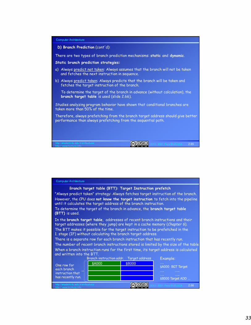
There are two types of branch prediction mechanisms: static and dynamic.
Static branch prediction strategies:
a) Always predict not taken: Always assumes that the branch will not be taken and fetches the next instruction in sequence.
b) Always predict taken: Always predicts that the branch will be taken and fetches the target instruction of the branch.
To determine the target of the branch in advance (without calculation), thebranch target table is used (slide 2.66).
Studies analyzing program behavior have shown that conditional branches are taken more than 50% of the time.
Therefore, always prefetching from the branch target address should give better performance than always prefetching from the sequential path.
D) Branch Prediction (cont'd):
Computer Architecture
2013 - 2021 Feza BUZLUCA 2.66http://akademi.itu.edu.tr/en/buzluca/http:// www.buzluca.info
"Always predict taken" strategy: Always fetches target instruction of the branch.
However, the CPU does not know the target instruction to fetch into the pipeline until it calculates the target address of the branch instruction.
To determine the target of the branch in advance, the branch target table (BTT) is used.
$A000 $B000
Branch instruction addr. Target address
In the branch target table, addresses of recent branch instructions and their target addresses (where they jump) are kept in a cache memory (Chapter 6).
The BTT makes it possible for the target instruction to be prefetched in the 1. stage (IF) without calculating the branch target address.
There is a separate row for each branch instruction that has recently run.
The number of recent branch instructions stored is limited by the size of the table.
When a branch instruction runs for the first time, its target address is calculated and written into the BTT.
One row for each branch instruction that has recently run.
Example:….$A000 BGT Target…. …..…. …..$B000 Target ADD …
Branch target table (BTT): Target Instruction prefetch

34
Computer Architecture
2013 - 2021 Feza BUZLUCA 2.67http://akademi.itu.edu.tr/en/buzluca/http:// www.buzluca.info
Dynamic branch strategies record the history of all conditional branch instructions in the active program to predict whether the condition will be true or not.
One or more prediction bits (or counters) are associated with each conditional branch instruction in a program that reflect the recent history of the instruction.
These prediction bits are kept in a branch history table – BHT (slide 2.69) and they provide information about the branch history of the instruction (branch was taken or not in previous runs).
Dynamic branch prediction strategies:
D) Branch Prediction (cont'd):
License: https://creativecommons.org/licenses/by-nc-nd/4.0/
Computer Architecture
2013 - 2021 Feza BUZLUCA 2.68http://akademi.itu.edu.tr/en/buzluca/http:// www.buzluca.info
For each conditional branch instruction (i), a single individual prediction bit (pi) is stored in the branch history table (BHT).
The prediction bit pi records only whether the last execution of this instruction (i) resulted in a branch or not.
If the branch was taken last time, the system predicts that the branch will be taken next time.
Algorithm:
Fetch the ith conditional branch instruction
If (pi = 0) then predict not to take the branch, fetch the next instruction in sequence
If (pi = 1) then predict to take the branch, prefetch the target instruction of the branch
If the branch is really taken, then pi ←1
If the branch is not really taken, then pi ←0
The initial value of pi is determined depending on the case in the first run of the conditional branch instruction.In the first run, the target address is calculated and stored in the BHT. During the calculation of the target address, next instructions in sequence (not the target of branch) are fetched into the pipeline. In case of a branch, there will be a branch penalty.
1-bit dynamic prediction scheme:

35
Computer Architecture
2013 - 2021 Feza BUZLUCA 2.69http://akademi.itu.edu.tr/en/buzluca/http:// www.buzluca.info
Branch target buffer and branch history table (BHT):
Prediction bits are kept in a high-speed memory location called the branch history table (BHT).
For each recent branch instruction in the current program, the BHT stores the address of the instruction, the target address, and the state (prediction) bits.
Each time a conditional branch instruction is executed the associated prediction bits are updated according to whether the branch is taken or not.
These prediction bits direct the pipeline control unit to make the decision the next time the branch instruction is encountered.
If the prediction is that "the branch will be taken", with the help of the target buffer, the target instruction of the branch can be prefetched without calculating the branch address.
Branch instruction addr. Target addressState(prediction) bits
BHT:Branch history table
Recent conditional branch instructions in the current program
Computer Architecture
2013 - 2021 Feza BUZLUCA 2.70http://akademi.itu.edu.tr/en/buzluca/http:// www.buzluca.info
Prediction mechanisms are advantageous if there are loops in the program.
Example:counter ← 100 ; register or memory location
LOOP ---- ; instructions in the loop----Decrement counter ; counter ← counter - 1 BNZ LOOP ; Branch if not zero (conditional branch, it has a p bit)
---- ; Next instruction after the loop
A) We assume that in the beginning of the given piece of code, the BNZ instruction is in the BHT and the value of its p bit is 1 (predict to take the branch).
In the first iteration (step) of the loop, the prediction at BNZ will be correct and the pipeline will prefetch the correct instruction (beginning of the loop).
The p bit (p=1) is not changed until the last iteration of the loop.
In the last iteration of the loop, the p bit is still 1, and the prediction is to take the branch; however, as the counter is zero, the program will not jump, and it will instead continue with the next instruction following the branch (misprediction).
The p bit of BNZ is cleared (p ← 0) because the branch is not taken in the last step.
As a result, in a loop with 100 iterations, there are 99 correct predictions and only one incorrect prediction.
Example: 1-bit dynamic prediction scheme and loops:

36
Computer Architecture
2013 - 2021 Feza BUZLUCA 2.71http://akademi.itu.edu.tr/en/buzluca/http:// www.buzluca.info
Example: 1-bit dynamic prediction scheme and loops (cont'd):
B) If in the beginning of the given piece of code, the BNZ instruction is not in the BHT, the system cannot make a prediction in the first run.
After the calculation of the target address of the BNZ, the related information is written into the BHT.
During the calculation of the target address, next instructions in sequence (not the target of branch) are fetched into the pipeline.
In the first run, the branch is taken, and the program jumps to the beginning of the loop, so there will be a branch penalty.
The initial value of p becomes 1 (predict that the branch will be taken).
The value of p (p = 1) does not change until the last iteration (step) of the loop.
In the last iteration of the loop, the p bit is still 1, and the prediction is that the branch will be taken; however, as the counter is zero, the program will not jump, and it will instead continue with the next instruction following the branch (misprediction).
The p bit of BNZ is cleared (p ← 0).
As a result, in a loop with 100 iterations, in the first iteration, a prediction cannot be made. Then, there are 98 correct predictions and one incorrect prediction. In total, there are 2 branch penalties.
Computer Architecture
2013 - 2021 Feza BUZLUCA 2.72http://akademi.itu.edu.tr/en/buzluca/http:// www.buzluca.info
In nested loops, a one-bit prediction scheme will cause twomispredictions for the inner loop:
• one in the first iteration, and • one on exiting
Problem with the 1-bit dynamic prediction scheme:
(Nested loops: the same loop is executed many times)
LOOP
BNZ LOOP
LOOP_EX. . .
. . .
BNZ LOOP_EX
Remember: in the previous example, after exiting the loop, the p bit of the inner BNZ LOOP was 0 ("don't take the branch") (p=0) .
Now, if the same loop runs again (2nd run), in the first iteration (step), the prediction about the BNZ will be "not to take the branch" (p=0).
However, the program will jump to the beginning of the loop (first misprediction).
Now, the p bit will be 1 because branch is taken (p ← 1).
Until the last iteration of the loop, predictions will be correct.
In the last iteration of the loop, there will be a misprediction as in the previous example (second misprediction).
Hence, misprediction will occur twice for each full iteration of the inner loop.

37
Computer Architecture
2013 - 2021 Feza BUZLUCA 2.73http://akademi.itu.edu.tr/en/buzluca/http:// www.buzluca.info
Predict taken
11
Predict taken
10
Not taken
Taken
Predict not
taken01
Predict not
taken00
Not taken
Taken
Taken Not taken
Taken
Not taken
2-bit Branch prediction scheme:
• If the instruction is in states 11 or 10, the scheme predicts that the branch will be taken.
• If the instruction is in states 00 or 01, the scheme predicts that the branch will not be taken.
In this scheme, the prediction changes only if it misses twice.
What really hapens at run-time
Prediction of the machine
Two prediction bits are associated with each conditional branch instruction.
License: https://creativecommons.org/licenses/by-nc-nd/4.0/
Computer Architecture
2013 - 2021 Feza BUZLUCA 2.74http://akademi.itu.edu.tr/en/buzluca/http:// www.buzluca.info
Example: 2-bit Branch prediction
State: 11 11 10 11 10 00 00 01 00 01 11Prediction: T T T T T N N N N N TActual: T√ N∅ T√ N∅ N∅ N√ T∅ N√ T∅ T∅ T√
The branch is actually taken
Prediction was correct √
The branch is actually not taken
Prediction was not correctMisprediction: ∅
2 mispredictionsState changes
2 mispredictionsState changes
From "Take" to "Not take"
From "Not take" to "Take"
T: Branch is TakenN: Branch is Not taken

38
Computer Architecture
2013 - 2021 Feza BUZLUCA 2.75http://akademi.itu.edu.tr/en/buzluca/http:// www.buzluca.info
Saturating counter: Another 2-bit Branch prediction strategyThere are different ways of implementing the finite state machine for branch prediction strategies.
A Saturating counter is one of these alternatives.
• If the instruction is in states 11 or 10, the scheme predicts that the branch will be taken.
• If the instruction is in states 00 or 01, the scheme predicts that the branch will not be taken.
Predict taken
11
Predict taken
10
Predict not
taken01
Predict not
taken00
Taken
Not taken
Not taken Not taken Not taken
TakenTakenTaken
In this scheme, the prediction is changed only if it misses twice after one correct prediction.
Computer Architecture
2013 - 2021 Feza BUZLUCA 2.76http://akademi.itu.edu.tr/en/buzluca/http:// www.buzluca.info
Counter1 ← 10LOOP1 ------ ; Any instruction
Counter2 ← 10LOOP2 ------ ; Any instruction
------ ; Any instructionCounter2 ← Counter2 - 1BNZ LOOP2 ; Branch if not zero------ ; Instruction after loop2Counter1 ← Counter1 - 1BNZ LOOP1 ; Branch if not zero------ ; Instruction after loop1
Problem:
A CPU has an instruction pipeline, where hardware-based mechanisms are used to solve branch hazards.This CPU runs the given piece of code below, which includes two nested loops.
For each branch prediction mechanism, give the number of correct predictions and mispredictions for the two branch instructions (BNZ) in the given piece of code.Briefly explain your results.
Example:

39
Computer Architecture
2013 - 2021 Feza BUZLUCA 2.77http://akademi.itu.edu.tr/en/buzluca/http:// www.buzluca.info
Solution:
a. Static prediction
i) Always predict not taken (For this method, a BTT (branch target table) is not necessary)
BNZ LOOP1: There is a correct prediction only in the last iteration (exit). Other predictions are incorrect.Correct : 1 Incorrect : 9
BNZ LOOP2: There is a correct prediction only in the last iteration (exit). Other predictions are incorrect.Correct : 10x1 = 10 Incorrect : 10x9 = 90
Total: Correct : 11 Incorrect : 99
This method is not suitable for loops.
Computer Architecture
2013 - 2021 Feza BUZLUCA 2.78http://akademi.itu.edu.tr/en/buzluca/http:// www.buzluca.info
ii-1) Always predict taken under the assumption that instructions are in the BTT
BNZ LOOP1: There is a misprediction only in the last iteration (exit). Other predictions are correct.
Correct: 9 Incorrect: 1
BNZ LOOP2: There is a misprediction only in the last iteration (exit).Other predictions are correct.
Correct : 10x9 = 90 Incorrect : 10x1 = 10
Total: Correct: 99 Incorrect: 11
ii-2) Always predict taken under the assumption that instr. are NOT in the BTT
BNZ LOOP1: There are mispredictions only in the first and last iterations. Other predictions are correct.
Correct: 8 Incorrect: 2
BNZ LOOP2: In the first run of the loop, there are mispredictions only in the first and last iterations; other predictions are correct.In the 2nd -10th runs, there is a misprediction only in the last iteration (exit).
Correct : 8+9x9 = 89 Incorrect : 2+9x1 = 11Total: Correct: 97 Incorrect: 13
a. Static prediction (cont'd)

40
Computer Architecture
2013 - 2021 Feza BUZLUCA 2.79http://akademi.itu.edu.tr/en/buzluca/http:// www.buzluca.info
Solution (cont’d):
b. Dynamic prediction with one bit
Note: Different prediction bits are used for each branch instruction (Slides 2.68, 2.69).
i) Assumption: In the beginning, instructions are in the BHT, and initial decision is to take the branch
BNZ LOOP1: There is a misprediction only in the last iteration (exit). Other predictions are correct.
Correct: 9 Incorrect: 1
BNZ LOOP2: In the first run of the loop, there is a misprediction only in the last iteration (exit).
Other predictions are correct.
After the first run, the prediction bit "p" changes to “branch will not be taken”.Therefore, in the 2nd-10th runs, there are mispredictions in both the first and last iterations (Slide 2.71).Correct: 9 + 9x8 = 81 Incorrect: 1+ 9x2 =19
Total: Correct: 90 Incorrect: 20
License: https://creativecommons.org/licenses/by-nc-nd/4.0/
Computer Architecture
2013 - 2021 Feza BUZLUCA 2.80http://akademi.itu.edu.tr/en/buzluca/http:// www.buzluca.info
b. Dynamic prediction with one bit (cont’d):
ii) In the beginning instructions are NOT in the BHT, or the initial decision is NOT to take the branch
BNZ LOOP1: There are mispredictions in the first and last iterations.
Other predictions are correct.
Correct: 8 Incorrect: 2
BNZ LOOP2: There are mispredictions in the first and last iterations.
Other predictions are correct.
Correct: 10x8 = 80 Incorrect: 10x2 =20
Total: Correct: 88 Incorrect: 22
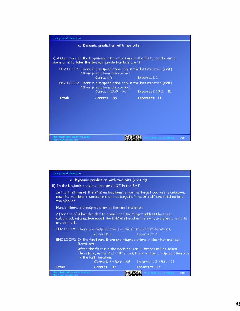
41
Computer Architecture
2013 - 2021 Feza BUZLUCA 2.81http://akademi.itu.edu.tr/en/buzluca/http:// www.buzluca.info
c. Dynamic prediction with two bits:
i) Assumption: In the beginning, instructions are in the BHT, and the initial decision is to take the branch, prediction bits are 11.
BNZ LOOP1: There is a misprediction only in the last iteration (exit).Other predictions are correct.
Correct: 9 Incorrect: 1
BNZ LOOP2: There is a misprediction only in the last iteration (exit).Other predictions are correct.
Correct: 10x9 = 90 Incorrect: 10x1 = 10
Total: Correct: 99 Incorrect: 11
Computer Architecture
2013 - 2021 Feza BUZLUCA 2.82http://akademi.itu.edu.tr/en/buzluca/http:// www.buzluca.info
c. Dynamic prediction with two bits (cont'd):
ii) In the beginning, instructions are NOT in the BHT
In the first run of the BNZ instructions, since the target address is unknown, next instructions in sequence (not the target of the branch) are fetched into the pipeline.
Hence, there is a misprediction in the first iteration.
After the CPU has decided to branch and the target address has been calculated, information about the BNZ is stored in the BHT, and prediction bits are set to 11.
BNZ LOOP1: There are mispredictions in the first and last iterations.
Correct: 8 Incorrect: 2
BNZ LOOP2: In the first run, there are mispredictions in the first and last iterations.
After the first run the decision is still “branch will be taken”. Therefore, in the 2nd - 10th runs, there will be a misprediction only in the last iteration.
Correct: 8 + 9x9 = 89 Incorrect: 2 + 9x1 = 11
Total: Correct: 97 Incorrect: 13


![Graphics Pipelinebarbic.usc.edu/cs420-s18/03-pipeline/03-pipeline.pdfLecture 3 Graphics Pipeline Graphics Pipeline Primitives: Points, Lines, Triangles [Angel Ch. 2] 1 . Graphics Pipeline](https://static.fdocuments.in/doc/165x107/611fe83badc8f839e462493e/graphics-lecture-3-graphics-pipeline-graphics-pipeline-primitives-points-lines.jpg)


