2-Color Display Digital Flow Switch - SMC Pneumatics … · 2014-08-01 · 2-Color Display Digital...
47
Flow rate range: 10, 25, 50,100 l/min. Minimum unit setting: 0.01 l/min. (0.1 l/min when the flow rate range is 25, 50, 100 l/min.) Repeatability: ±1%F.S. or less Grease-free Flow adjustment valve is integrated. (Reduced piping and space saving) Response time: Either 50 msec., 0.5 sec., 1 sec. or 2 sec. can be chosen. Flow adjustment valve Irregular value at a glance 2-color display 2-color display Air, N2, Ar, CO2 Fluid Fluid ® Series PFM 2-Color Display Digital Flow Switch 899 PFM PFMV PF2A PF2W PF2D IF
Transcript of 2-Color Display Digital Flow Switch - SMC Pneumatics … · 2014-08-01 · 2-Color Display Digital...

Flow rate range: 10, 25, 50,100 l/min.
Minimum unit setting: 0.01 l/min.(0.1 l/min when the flow rate range is 25, 50, 100 l/min.)
Repeatability: ±1%F.S. or less
Grease-free
Flow adjustment valve is integrated.(Reduced piping and space saving)
Response time:Either 50 msec., 0.5 sec., 1 sec. or 2 sec. can be chosen.
Flow adjustment valve
Irregular value at a glance
2-color display2-color display
Air, N2, Ar, CO2
FluidFluid
®
Series PFM2-Color Display Digital Flow Switch
899
PFM
PFMV
PF2A
PF2W
PF2D
IF
P0898-P0970-E.qxd 08.8.27 7:07 PM Page 899

Flow characteristics
0 Number of needle rotations
Flo
w r
ate
Power supply /Output connector
e-con connectorSensor connector
Flashing speedFastSlow
Flow rateHighLow
Flashing
SET SET SET
OUT1 OUT2OUT1 OUT2OUT1 OUT2
�34.5
Panel opening
( ): Fluid: CO2
Integrated type
Measurement flow range(l/min)
Remote type
Model
PFM710PFM725PFM750PFM711
PFM510PFM525PFM550PFM511
0.2 to 10 (0.2 to 5)0.5 to 25 (0.5 to 12.5) 1 to 50 (1 to 25) 2 to 100 (2 to 50)
PFM3��
ModelSensor unit Display unit
A single panel opening is sufficient. Reduces panel fitting work and enables space-savings.
Support for vertical and horizontal secure mounting (panel mount)
2-Color Display Digital Flow Switch2-Color Display Digital Flow Switch
Piping variationsOne-touch fittings, female threads, straight piping, and bottom piping are selectable.
ConnectorsConnection and removal of wiring is easy.
Integrated flow adjustment valveReduces piping installation work and space requirements. Special design pro-vides smooth adjustment to match needle rotations.
Indicator functionFlashing speed varies according to flow rate. Color changes from green to red when rated flow rate is exceeded. Can be used as a simple monitor.
Series PFM7
Series PFM5
Series PFM3
900
P0898-P0970-E.qxd 08.8.27 7:07 PM Page 900

1 2S
IN
1
1 2S
IN
1
12
S
IN
1 2S
IN
12
S
IN
12
S
IN
1 2S
IN
1
1 2S
IN
1
116
1834
68
67
43Straight piping length
48
241.6
88
Series PFMSeries PFMSeries PFM
Lightweight: 55 gLightweight: 55 g (PFM711)(PFM711)(With one-touch fitting, without flow adjustment valve)
CompactCompactCompact
Reduced piping spaceReduced piping space
Same size even when the model with different flow rate range (10, 25, 50, 100 l/min) is chosen.
Conventional model PF2A711: 290 g
Mountable in a narrow location since the straight piping length∗ is not required.∗ A straight piping length of 8 times
the piping diameter is required for the conventional model.
Lightweight: 55 g (PFM711)
Reduced piping spaceComparison with the conventional model
PF2A711 (10 to 100 l/min)
Comparison with the conventional model PF2A711 (10 to 100 l/min)when ø6 one-touch fittings are attached.
Female thread: Rc 1/8, 1/4 � NPT 1/8, 1/4 � G 1/8, 1/4One-touch fitting: ø4, ø6, ø8, ø1/4
BottomStraightBottomStraight
Piping Variations
Wit
ho
ut
flo
w a
dju
stm
ent
Wit
hfl
ow
ad
just
men
t
Mounting
Panel mount
BracketBottom mounting
DIN rail
Through-holemounting
901
PFM
PFMV
PF2A
PF2W
PF2D
IF
P0898-P0970-E.qxd 08.8.27 7:07 PM Page 901

The accuracy may fluctuate by 2 to 3% just after replacement.(Repeatability does not change.)
Suctionfilter
ZFSFD100
PFM
Flowswitch
Vacuum line
Vacuum line
Dryer
IDFIDU
AF ARIR
AMDAFD
PFM
Air filter Regulator Micro mistseparator
Flowswitch
The decimal point indicators flash in power-saving mode.
Flashing Flashing
For details and other functions, refer to page 939.
Selection of fluidAir, Nitrogen (N2), Argon (Ar) or Carbon dioxide (CO2) can be selected using the buttons.
Secret code setting functionThe user must input a secret code to cancel the keylock mode. This ensures that only authorized persons can operate the switch.
Power-saving modeTurning off the display can save power consumption.
� Selection of indication unit
User can select between ANR and Nl/min for each fluid.[ANR] Indicates the flow rate converted to a volume under standard conditions: 20°C, 1 atm
(atmosphere), 65%RH[N l/min] Indicates the flow rate converted to a volume under normal conditions: 0°C, 1 atm (atmosphere).
� External input Can be selected from accumulated value external reset, auto-shift and auto-shift zero.
� Indication resolution
Minimum unit setting can be selected from 1 l/min, 0.1 l/min and 0.01 l/min. Depends on the model. Refer to the specifications (P. 939) for details.
Refer to page 932 for details.
Several CombinationsDepending on the installation conditions, it is possible to add or remove the flow adjustment valve, change the fitting type and the piping direction as desired.
Clip
One-touch fitting
Flow adjustmentvalve
Female thread
Compressed air line
Recommended Air Circuits
Control of metal wire tension
Suction check
• Accumulated indication shows the operating flow rate or residual amount (of N2 etc.) in a gas cylinder.
Detection camera
• Flow control of N2 gas to prevent lead frame oxidation.
• N2 blow prevents distortion of camera image due to air turbulence.
Welder Models compatible with argon (Ar) and carbon dioxide (CO2) mixed gas are available. Refer to page 942 for details.
Applications
Main Functions
902
P0898-P0970-E.qxd 08.8.27 7:07 PM Page 902

ON
OFF
ON
OFF
Indicated value is the same at any installation position. (No conversion is needed.)
Indicated value depends on installation position. (Conversion is required.)
Indicated value depends on the viewing angle.
Mounting orientation is not limited.
Verticalorientation
only
� Digital display
� Not subject to pressure variations
� Free mounting orientation
� With switch output and analog output
Control by sensor output Visual control
Can detect whether greater or less than set flow rate. The flow condition can be controlled all the time.
Can only detect when float passes. Cannot detect whether greater or less than set flow rate.
A photoelectric switch, or similar, must be prepared separately.
With switch outputand analog output
Without output function
Less Flowrate
Less Flowrate
Greater Greater
Notdisplayable
Able to confirm the total air consumption per day (Max. 999999 l )Accumulated pulse outputis also equipped.
� Accumulated flow display
Comparison with Float Type Flow Meter
903
PFM
PFMV
PF2A
PF2W
PF2D
IF
P0898-P0970-E.qxd 08.8.27 7:07 PM Page 903

Features P. 900 to 903
How to Order P. 906
Specifications P. 908
Piping Specifications / Mass P. 909
Analog Output P. 909
Internal Circuits and Wiring Examples P. 909
Dimensions P. 910
Pressure Loss / Flow Characteristics P. 930
Parts Description P. 931
Construction P. 931
Detection Principle P. 931
Component Parts P. 932
How to Order P. 918
Specifications P. 920
Piping Specifications / Mass P. 921
Analog Output P. 921
Internal Circuits and Wiring Examples P. 921
Dimensions P. 922
Series PFM7 Integrated Display
Made to Order
Series PFM7, PFM5CommonSpecifications
Changing the piping entry direction P. 940combination for IN and OUT side
Compatible with argon (Ar) and carbon P. 942dioxide (CO2) mixed gas
Specific Product Precautions P. 943
How to Order P. 933
Specifications P. 934
Analog Output P. 934
Internal Circuits P. 935
Descriptions P. 936
Dimensions P. 937
Function Details P. 939
2-Color Display Digital Flow Switch
Series PFM5 Remote Sensor Unit
Series PFM3 Flow Sensor Monitor
905
PFM
PFMV
PF2A
PF2W
PF2D
IF
P0898-P0970-E.qxd 08.8.27 7:07 PM Page 905

How to Order
PFM7 10 C4 A M
12
S
IN
1 2S
IN
1
1 2S
IN
1 2S
IN
1
12
S
IN
12
S
IN
1 2S
IN
1
1 2S
IN
1
®
2-Color DisplayDigital Flow Switch
Series PFM7Integrated
display
Integrateddisplay
Unit specification
Note) Fixed unit: Real-time flow rate: l/minAccumulated flow: l
Fixed SI unit Note)
With unit switching functionMNil
TypeIntegrated display7
Flow adjustment valveNilS
NoneYes
Calibration certificateNone
With calibration certificateNilA
∗ The certificate is written in English and Japanese. Other languages are available as specials.
Instruction manualWith instruction manual (Leaflet: Japanese and English)
NoneNilN
Note 3) User can select from accumulated value external reset, auto-shift and auto-shift zero.
Output specificationABCDEFGH
2 NPN outputs2 PNP outputs1 NPN output + Analog (1 to 5 V)1 NPN output + Analog (4 to 20 mA)1 PNP output + Analog (1 to 5 V)1 PNP output + Analog (4 to 20 mA)1 NPN output + External input Note 3)
1 PNP output + External input Note 3)
Piping entry directionNilL
StraightBottom
Port size
Symbol DescriptionFlow rate range
10�
�
�
��
25�
�
�
���
50�
�
�
���
11
�
�
�
���
0102
N01N02F01F02C4C6C8N7
ø4 (5/32") one-touch fittingø6 one-touch fitting
ø8 (5/16") one-touch fittingø1/4" one-touch fitting
Rc1/8Rc1/4
NPT1/8NPT1/4
G1/8G1/4
0.2 to 10 (5) l/min0.5 to 25 (12.5) l/min1 to 50 (25) l/min2 to 100 (50) l/min
10255011
∗ ( ): Fluid: CO2
Rated flow range (Flow rate range)
Option 1 (Refer to page 907.)
Option 2 (Refer to page 907.)
Made to Order(Refer to page 907 and 940.)
∗ Different combinations of piping entry directions for IN and OUT side are available as made-to-order. (Refer to page 940.)
With one-touch fittings (C4, C6, C8, N7) Female thread (01, 02, N01, N02, F01, F02)
Straight (Nil)
Withoutflow
adjustmentvalve(Nil)
Withflow
adjustmentvalve
(S)
Bottom (L) Straight (Nil) Bottom (L)
Piping Variations
906
P0898-P0970-E.qxd 08.8.27 7:07 PM Page 906

Option 2
DIN Rail Mounting Bracket (Order Separately)
ZS-33-JZS-33-M ZS-33-MS
ZS 33 RStations
1 station2 stations3 stations4 stations5 stations
12345
NilNone
VPanel mount adapter
(For with flow adjustment valve)
RBracket
(For without flow adjustment valve)
SBracket
(For with flow adjustment valve)
Piping direction: Cannot be mounted with bottom piping type.
TPanel mount adapter
(For without flow adjustment valve)
ZS-33-JS
Made to Order
X693X694
X731
Change of piping entry directioncombination
Compatible with argon (Ar) and carbon dioxide (CO2) mixed gas
Specification/DescriptionSymbol
For details, refer to page 940 through to 942.
Mounting bracket
Panel mountadapter B
Panel mountadapter A
Panel
Panel mountadapter A
Panel
Panel mountadapter B
Mounting bracket
Mountingscrew(accessory)
Mountingscrew(accessory)
Each option is not assembled with the product, but shipped together.
Option 1Nil
With lead wire with connector (2 m)
ZWithout lead wire with connector
ZS-33-D1
2S
IN
Lead wire length 2 m
WWith lead wire with connector (2 m) +Rubber cover for connector (silicon rubber)
ZS-33-F
ZS-33-D1
2S
IN
Lead wire length 2 m
• DIN rail (supplied by customers)• Port size F02: G1/4 cannot be mounted on the DIN rail.
907
2-Color Display Digital Flow Switch Series PFM7
PFM
PFMV
PF2A
PF2W
PF2D
IF
P0898-P0970-E.qxd 08.8.27 7:07 PM Page 907

Specifications
Note 1) When the minimum unit setting 0.01 l/min is selected for 10 l/min type, the indication upper limit will be [9.99 l/min].When the minimum unit setting 0.1 l/min is selected for 100 l/min type, the indication upper limit will be [99.9 l/min].
Note 2) User can select between 0.01 l/min and 0.1 l/min for the PFM710, and between 0.1 l/min and 1 l/min for the PFM711 respectively.If the indication unit is selected to “CFM”, the minimum unit setting cannot be changed.At the time of shipment from the factory, the minimum unit setting is set to 0.1 l/min for the PFM710 and 1 l/min for the PFM711 respectively.
Note 3) Set to “ANR” at the time of shipment from the factory.“ANR” is used for standard conditions: 20°C, 1 atm and 65%R.H.“N l/min” is used for normal conditions: 0°C and 1 atm.When equipped with a unit switching function. (The SI unit (l/min or l) is fixed for types with no unit switching function.)
Note 4) Cleared when the power supply is turned off. Hold function can be selected. (Interval of 2 min or 5 min can be selected).If the 5 min interval is selected, the life of the memory element (electronic part) is limited to 1 million cycles. (If energized for 24 hours, life is calculated as 5 min x 1 million = 5 million min = 9.5 years). Therefore, if using the hold function, calculate the memory life for your operating conditions, and use within this life.
Note 5) Set to 1.5 s (90%), can be changed to 100 ms.Note 6) Set to hystresis mode at the time of shipment from the factory. Can be changed to window comparator mode using push-buttons.
Model PFM710 PFM725 PFM750 PFM711
Applicable fluid
Pressure characteristics
Repeatability
Operating pressure range
Rated pressure range
Proof pressure
Accumulated flow range
Switch output
Accumulated pulse output
External input
Display method
Status LED’s
Power supply voltage
Current consumption
Environ-mentalresistance
Indication unit Note 3)
Minimum unit setting Note 2)
Accumulated pulse flow rate exchange value
Rated flow range(Flow rate range)
Dry air, N2, Ar
CO2
Maximum load current
Maximum applied voltage
Internal voltage drop
Response time
Output protection
Enclosure
Operating fluid temperature
Operating temperature range
Operating humidity range
Withstand voltage
Insulation resistance
Hysteresis mode
Window comparator mode
Response time
Displayable range Note 1)
Settable range Note 1)
Dry air, N2, Ar
CO2
Dry air, N2, Ar
CO2
Dry air, N2, Ar, CO2
(Air quality grade is JIS B8392.1-1, 1.2 to 1.6.2 and ISO8573.1-1, 1.2 to 1.6.2.)
0.2 to 10 l/min
0.2 to 5 l/min
0.2 to 10.5 l/min
0.2 to 5.2 l/min
0 to 10.5 l/min
0 to 5.2 l/min
0.5 to 25 l/min
0.5 to 12.5 l/min
0.5 to 26.3 l/min
0.5 to 13.1 l/min
0 to 26.3 l/min
0 to 13.1 l/min
±1%F.S. or less (Fluid: Dry air)Analog output accuracy: ±3%F.S. or less
±5%F.S. or less (based on 0.35 MPa)
–100 kPa to 750 kPa
–70 kPa to 750 kPa
1 MPa
Max. 999999 l Note 4)
NPN or PNP open collector output
80 mA
28 VDC (at NPN output)
NPN output: 1 V or less (at 80 mA) PNP output: 1.5 V or less (at 80 mA)
1 s (50 ms, 0.5 s, 2 s can be selected.)
Short-circuit protection, Overcurrent protection
NPN or PNP open collector output (Same as switch output)
1.5 s or less (90% response)
Variable
Variable
No-voltage input (Reed or Solid state) Input 30 ms or more
3-digit, 7-segment LED 2-color display (Red/Green) Renewed cycle: 10 times/sec
OUT1: Illuminates when output is turned ON (Green). OUT2: Illuminates when output is turned ON (Red).
24 VDC ± 10%
55 mA or less
IP40
0 to 50°C (with no freezing and condensation)
Operating: 0 to 50°C Stored: –10 to 60°C (with no freezing and condensation)
Operating, Stored: 35 to 85%R.H. (with no condensation)
1000 VAC for 1 min. between external terminal and case
50 MΩ or more (500 VDC Mega) between external terminal and case
490 m/s2 in X, Y, Z directions 3 times each
Real-time flow rate l/min, CFM x 10-2
Accumulated flow l, ft3 x 10-1
±2%F.S. (15 to 35°C)±5%F.S. (0 to 50°C)
Voltage output: 1 to 5 VOutput impedance: 1 kΩ
Current output: 4 to 20 mAMax. load impedance: 600 Ω, Min. load impedance: 50 Ω
Without orifice: 10 to 500 Hz with a 1.5 mm amplitude or 98 m/s2 acceleration, in each X, Y, Z direction for 2 hrs, whichever is smaller.With orifice: 10 to 150 Hz with a 1.5 mm amplitude or 19.6 m/s2 acceleration, in each X, Y, Z direction for 2 hrs, whichever is smaller.
Linearity
Temperature characteristics
Analog output Note 5)
Hysteresis Note 6)
Display accuracy: ±3%F.S. or less (Fluid: Dry air)Analog output accuracy: ±5%F.S. or less
1 to 50 l/min
1 to 25 l/min
1 to 52.5 l/min
1 to 26.2 l/min
0 to 52.5 l/min
0 to 26.2 l/min
2 to 100 l/min
2 to 50 l/min
2 to 105 l/min
2 to 52 l/min
0 to 105 l/min
0 to 52 l/min
Voltage output
Current output
Vibration resistance
Impact resistance
0.01 l/min
0.1 l/pulse
0.1 l/min
0.1 l/pulse
0.1 l/min
0.1 l/pulse
0.1 l/min
1 l/pulse
908
Series PFM7
P0898-P0970-E.qxd 08.8.27 7:07 PM Page 908

Piping Specifications / Mass
Analog Output Note: Analog output at maximum rated flow rate when CO2 is selected is 3 [V] for the voltage output type and 12 [mA] for the current output type.
Part no. 01
Port size
Mass
Wetted parts material
Straight Without orifice: 125 gBottom Without orifice: 135 gStraight With orifice: 165 gBottom With orifice: 175 g
Straight Without orifice: 55 gBottom Without orifice: 65 gStraight With orifice: 95 gBottom With orifice: 105 g
Straight Without orifice: 95 gBottom Without orifice: 105 gStraight With orifice: 135 gBottom With orifice: 145 g
LCP, PBT, Brass (Electroless nickel plated), HNBR (+ Fluoro coated), FKM (+ Fluoro coated), Silicon, Au, Stainless steel 304
Rc1/8
02
Rc1/4
N01
NPT1/8
N02
NPT1/4
F01
G1/8 G1/4
C4F02ø4
(5/32")one-touch
fitting
C6
ø6one-touch
fitting
C6ø8
(5/16")one-touch
fitting
N7
ø1/4"one-touch
fitting
10
25
50
100
PFM710-�-C/EPFM725-�-C/EPFM750-�-C/EPFM711-�-C/E
Analog Voltage Output (1 to 5 V)
ModelMax. ratedflow value
[l/min]
10 (5)
25 (12.5)
50 (25)
100 (50)
PFM710-�-D/FPFM725-�-D/FPFM750-�-D/FPFM711-�-D/F
Analog Current Output (4 to 20 mA)
ModelMax. ratedflow value
[l/min]
Max. ratedflow value
0
4
20
Ana
log
outp
ut [V
]
Ana
log
outp
ut [m
A]
Max. ratedflow value
00 0
1
5
2 NPN outputs type PFM7���-��-A-��NPN + Analog output type PFM7���-��-C-��/PFM7���-��-D-��NPN + External input type PFM7���-��-G-��
2 PNP outputs type PFM7���-��-B-��PNP + Analog output type PFM7���-��-E-��/PFM7���-��-F-��PNP + External input type PFM7���-��-H-��
Max. 80 mA
Brown DC (+)
Black OUT1
White OUT2 (PFM7����-��-B-�� only)
Load
Load
50 msec
0 V
50 msec
or
50 msec
0 V
50 msec
or
Accumulated pulse output wiring examples
Black OUT1
White OUT2 (PFM-7����-��-A-�� only)
Blue DC (–)
Load
Load
Max. 28 V, 80 mA
Max. 28 V, 80 mAInternal voltage drop 1 V or less
Brown DC (+)
Black OUT1
White OUT2
Blue DC (–)
24 VDC
Load
Load
Max. 80 mAInternal voltage drop 1.5 V or less
24 VDC
Brown DC (+)
Black OUT1
White OUT2
Blue DC (–)
Load
Load
Max. 28 V, 80 mAInternal voltage drop 1 V or less
External input: No-voltage inputReed switch or solidstate switch input30 msec or more
Brown DC (+)
Black OUT1White External input
Blue DC (–)
24 VDC
Load
Max. 28V, 80 mAInternal voltage drop 1 V or less
C: Analog output 1 to 5 VOutput impedance 1 kΩ
D: Analog output 4 to 20 mALoad impedance 50 to 600 Ω
Brown DC (+)
Black OUT1
Blue DC (–)
24 VDCWhite Analog output
Load
Load
Max. 80 mAInternal voltage drop 1.5 V or less
E: Analog output 1 to 5 VOutput impedance 1 kΩ
F: Analog output 4 to 20 mALoad impedance 50 to 600 Ω
24 VDC
Brown DC (+)
Black OUT1White Analog output
Blue DC (–)
Load
Load
Max. 80 mAInternal voltage drop 1.5 V or less
External input: No-voltage inputReed switch or solidstate switch input30 msec or more
Brown DC (+)
Black OUT1White External input
Blue DC (–)
24 VDCLoad
2 NPN outputs type PFM7���-��-A-��
2 PNP outputs type PFM7���-��-B-��
NPN + External input type PFM7���-��-G-��
NPN + Analog output type PFM7���-��-C-��NPN + Analog output type PFM7���-��-D-��
PNP + Analog output type PFM7���-��-E-��PNP + Analog output type PFM7���-��-F-��
PNP + External input type PFM7���-��-H-��
Internal Circuits and Wiring Examples∗ ( ): Fluid: CO2
Mai
n ci
rcui
t
Mai
n ci
rcui
t
Mai
n ci
rcui
t
Mai
n ci
rcui
t
Mai
n ci
rcui
t
Mai
n ci
rcui
t
909
2-Color Display Digital Flow Switch Series PFM7
PFM
PFMV
PF2A
PF2W
PF2D
IF
P0898-P0970-E.qxd 08.8.27 7:07 PM Page 909

Dimensions
PFM7��-C4/C6/C8/N7
(mm)
One-touch fittingApplicable tube O.D.
ø4 (5/32")
ø6
ø8 (5/16")
ø1/4"
A
64.2
64.6
68
64.6
PFM7��-C4L/C6L/C8L/N7L
(mm)
One-touch fittingApplicable tube O.D.
ø4 (5/32")
ø6
ø8 (5/16")
ø1/4"
A
10.1
10.3
12
10.3
18
48
A
1 IN
OUT1
DC (–)
OUT2
DC (+)
2 x one-touch fitting
1 IN
2 x one-touch fitting
OUT1
DC (–)
OUT2
DC (+)
18
48
88
18
68
10.2
3
(34.
2)
143
A
2 x 3.4 OUTIN
18
10.2
143
3
13
(34.
2)
2 x 3.4
IN OUT
28
8
2 x 2.6 depth 5
28
8
2 x 2.6 depth 5
910
Series PFM7
P0898-P0970-E.qxd 08.8.27 7:07 PM Page 910

PFM7��-(N)01/(N)02/F01
PFM7��-(N)01L/(N)02L/F01L
48
70
Wid
th a
cros
s fla
ts 1
7
18
1 IN
2 x port size
Rc 1/8, 1/4NPT 1/8, 1/4G 1/8
DC (+)DC (–)
OUT2OUT1
2 x 3.4
18
143
13
10.2
3
(34.
2) IN OUT
88
48
18
1 IN
Width across flats 17
DC (+)DC (–)
OUT2OUT1
2 x port size
Rc 1/8, 1/4NPT 1/8, 1/4G 1/8
68
3
(34.
2)
18
43
10.2
113
2 x 3.4IN OUT
28
8
2 x 2.6 depth 5
8
28
8
2 x 2.6 depth 5
Dimensions
911
2-Color Display Digital Flow Switch Series PFM7
PFM
PFMV
PF2A
PF2W
PF2D
IF
P0898-P0970-E.qxd 08.8.27 7:07 PM Page 911

PFM7��-F02
PFM7��-F02L
1 IN
18
OUT1
DC (–)
OUT2
DC (+)
2 x port size
G 1/418
10.2
13
(34.
2)431
3
2 x 3.4
IN OUT
48
78
Wid
th a
cros
s fla
ts 2
1
1 IN
Width across flats 21
DC (+)
OUT2
2 x port sizeG 1/4
OUT1
DC (–)
88
48
18
18
2 x 3.4
68
1743
1
3
(34.
2)
10.2
IN OUT
2 x 2.6 depth 5
8
28
8
28
2 x 2.6 depth 5
Dimensions
912
Series PFM7
P0898-P0970-E.qxd 08.8.27 7:07 PM Page 912

PFM7�S-C4/C6/C8/N7
(mm)
One-touch fittingApplicable tube O.D.
ø4 (5/32")
ø6
ø8 (5/16")
ø1/4"
A
92.2
92.6
96
92.6
PFM7�S-C4L/C6L/C8L/N8L(mm)
One-touch fittingApplicable tube O.D.
ø4 (5/32")
ø6
ø8 (5/16")
ø1/4"
A
10.1
10.3
12
10.3
18
48
58
88
1 IN
DC (+)DC (–)
OUT2OUT1
2 x one-touch fitting
10.2
3
(34.
2)
A43
1
18
68
51.5
(M
ax. 5
8.5)
2 x 3.4IN OUT
1 IN
DC (–)
OUT1
DC (+)
OUT2
2 x one-touch fitting
18
48
58
76
A
51.5
(M
ax. 5
8.5)
13
(34.
2)
3
10.2
431
18
2 x 3.4
IN OUT
28 20
8
3 x 2.6 depth 5
2 x 2.6 depth 5
28
8
Dimensions
913
2-Color Display Digital Flow Switch Series PFM7
PFM
PFMV
PF2A
PF2W
PF2D
IF
P0898-P0970-E.qxd 08.8.27 7:07 PM Page 913

PFM7�S-(N)01/(N)02/F01
PFM7�S-(N)01L/(N)02L/F01L
1 IN
Width across flats 17
DC (+)DC (–)
OUT2OUT1
2 x port size
Rc 1/8, 1/4NPT 1/8, 1/4G 1/8
48
58
88
18
10.2
3
(34.
2)
18
68
1343
1
51.5
(M
ax. 5
8.5)
2 x 3.4IN OUT
1 IN
DC (–)
OUT1 OUT2
DC (+)
2 x port size
Rc 1/8, 1/4NPT 1/8, 1/4G 1/8
18
48
58
76
98
Wid
th a
cros
s fla
ts 1
7
18
13
(34.
2)431
10.2
51.5
(M
ax. 5
8.5)
3
2 x 3.4
IN OUT
28 20
8
3 x 2.6 depth 5
2 x 2.6 depth 5
28
8
Dimensions
914
Series PFM7
P0898-P0970-E.qxd 08.8.27 7:07 PM Page 914

PFM7�S-F02
PFM7�S-F02L
1 IN
Width across flats 212 x port size
OUT2
DC (+)DC (–)
OUT1
G 1/4
18
88
58
48
51.5
(M
ax. 5
8.5)
68
2 x 3.4
181743
3
(34.
2)
1
10.2
IN OUT
1 IN
2 x port size
G 1/4
OUT2
DC (+)
OUT1
DC (–)
Wid
th a
cros
s fla
ts 2
1
106
76
58
48
18
2 x 3.4
51.5
(M
ax. 5
8.5)
10.2
18
431
13
(34.
2)
3IN OUT
28 20
8
3 x 2.6 depth 5
28
8
2 x 2.6 depth 5
Dimensions
915
2-Color Display Digital Flow Switch Series PFM7
PFM
PFMV
PF2A
PF2W
PF2D
IF
P0898-P0970-E.qxd 08.8.27 7:07 PM Page 915

Panel mount / Without flow adjustment valve / Straight Panel mount / With flow adjustment valve / Straight
Panel mount / Without flow adjustment valve Panel mount / With flow adjustment valve
(mm)
One-touch fittingApplicable tube O.D.
ø4 (5/32")
ø6
ø8 (5/16")
ø1/4
A
92.2
92.6
96
92.6
(mm)
One-touch fittingApplicable tube O.D.
ø4 (5/32")
ø6
ø8 (5/16")
ø1/4
A
64.2
64.6
68
64.6
A
58
2829.9
OUT
Pan
el th
ickn
ess
1 to
3.2
42.5
3
IN
78
2829.9
3
Pan
el th
ickn
ess
1 to
3.2
51.5
(M
ax. 5
8.5)
76
A42
.53
93
78
182829.9
42.5
3
Pan
el th
ickn
ess
1 to
3.2
51.5
(M
ax. 5
8.5)
29.9
28 18
88
58
342
.5
Pan
el th
ickn
ess
1 to
3.2
Note) Piping entry direction: Minimum dimensions for bottom side piping. If using straight piping, the piping material and tubing need to be taken into consideration when designing the system. If a bend (R) is used, limit it to R3 or less.
Panel Fitting Dimensions
Panel thickness 1 to 3.2 mm
Note) Piping entry direction: Minimum dimensions for bottom side piping. If using straight piping, the piping material and tubing need to be taken into consideration when designing the system. If a bend (R) is used, limit it to R3 or less.
Panel Fitting Dimensions
Panel thickness 1 to 3.2 mm
94 or more Note)
74 +0.50
34 o
r m
ore
24+
0.5
0
94 or more Note)
54 +0.50
34 o
r m
ore
24+
0.5
0
4 x R3 or less
4 x R3 or less4 x R3 or less
4 x R3 or less 4 x R3 or less4 x R3 or less
Dimensions
916
Series PFM7
P0898-P0970-E.qxd 08.8.27 7:07 PM Page 916

5 ±2
6.5
+21–
2020+50
0
200
–5
30 ±3
Terminal semi-stripped
18 x n pcs. + 34.4
18
48
11IN1 IN IN
43
52.4
34 26 18
24 28
76
4 x 3
.4
36
431.
2
48
18
1.2
51.5
(M
ax. 5
8.5)
18
4348
48
36
28
34 26 18
4 x 3.4
• DIN rail (supplied by customers)• Port size, F02: G1/4 cannot be mounted on the DIN rail.
With bracket / Without flow adjustment valve With bracket / With flow adjustment valve
DIN rail mounting
Cable Specifications of Lead Wire with Connector
Insulation
Finished external diameter
Nominal cross section area
Material
Construction
External diameter
Material
External diameter
Colors
Material
Color
Rated temperature
Rated voltage
Number of wires
Conductor
Sheath
80°C30 V
4
AWG26
Soft copper wire
28 / 0.08 mm
Approx. 0.50 mm
Cross-linked vinyl chloride resin compound
Approx. 1.00 mm
Brown, White, Black, Blue
Oil-resistant vinyl chloride resin compound
Light gray
ø3.5 +0.10–0.25
Lead wire with connectorZS-33-D
Dimensions
Brown
White
Black
Blue
917
2-Color Display Digital Flow Switch Series PFM7
PFM
PFMV
PF2A
PF2W
PF2D
IF
P0898-P0970-E.qxd 08.8.27 7:07 PM Page 917

How to Order
2-Color DisplayDigital Flow Switch
Series PFM5Remote
sensor unit
PFM5 10 C4 1Type
Remote sensor unit5
Flow adjustment valveNilS
NoneYes
Calibration certificateNone
With calibration certificateNilA
∗ The certificate is written in English and Japanese. Other languages are available as specials.
Instruction manualWith instruction manual (Leaflet: Japanese and English)
NoneNilN
Output specificationNo.12
DescriptionAnalog output (1 to 5 V)Analog output (4 to 20 mA)
Applicable display unitPFM30�PFM31�
Piping entry directionNilL
StraightBottom
Port size
∗ Different combinations of piping entry directions for IN and OUT side are available as made-to-order. (Refer to page 940.)
0.2 to 10 (5) l/min0.5 to 25 (12.5) l/min1 to 50 (25) l/min2 to 100 (50) l/min
10255011
∗ ( ): Fluid: CO2
Rated flow range (Flow rate range)
Option 1 (Refer to page 919.)
Option 2 (Refer to page 919.)
Made to Order(Refer to page 919 and 940.)
Remotesensor unit
Symbol DescriptionFlow rate range
10�
�
�
��
25�
�
�
���
50�
�
�
���
11
�
�
�
���
0102
N01N02F01F02C4C6C8N7
Rc1/8Rc1/4
NPT1/8NPT1/4
G1/8G1/4
ø4 (5/32") one-touch fittingø6 one-touch fitting
ø8 (5/16") one-touch fittingø1/4" one-touch fitting
®
With one-touch fittings (C4, C6, C8, N7) Female thread (01, 02, N01, N02, F01, F02)
Straight (Nil)
Withoutflow
adjustmentvalve(Nil)
Withflow
adjustmentvalve
(S)
Bottom (L) Straight (Nil) Bottom (L)
Piping Variations
918
P0898-P0970-E.qxd 08.8.27 7:07 PM Page 918

DIN Rail Mounting Bracket (Order Separately)
ZS-33-JZS-33-M ZS-33-MS
ZS 33 RStations
1 station2 stations3 stations4 stations5 stations
12345
NilNone
VPanel mount adapter
(For with flow adjustment valve)
Option 1Nil
With lead wire with connector (2 m)
RBracket
(For without flow adjustment valve)
SBracket
(For with flow adjustment valve)
Piping direction: Cannot be mounted with bottom piping type.
TPanel mount adapter
(For without flow adjustment valve)
ZWithout lead wire with connector
Option 2
ZS-33-D
ZS-33-JS
Mounting bracket
Panel mountadapter B
Panel mountadapter A
Panel
Panel mountadapter A
Panel
Panel mountadapter B
Mounting bracket
Mountingscrew(accessory)
Mountingscrew(accessory)
Lead wire length 2 m Lead wire length 2 m
Each option is not assembled with the product, but shipped together.
Made to Order
X693X694
Change of piping entry directioncombination
Specification/DescriptionSymbol
For details, refer to page 940 and 941.
WWith lead wire with connector (2 m) +Rubber cover for connector (silicon rubber)
ZS-33-F
ZS-33-D
• DIN rail (supplied by customers)• Port size F02: G1/4 cannot be mounted on the DIN rail.
919
2-Color Display Digital Flow Switch Series PFM5
PFM
PFMV
PF2A
PF2W
PF2D
IF
P0898-P0970-E.qxd 08.8.27 7:07 PM Page 919

Note: Flow rate unit is based on standard conditions (20°C, 1 atm, 65% RH).
Model PFM510 PFM525 PFM550 PFM511
Applicable fluid
Pressure characteristics
Power supply voltage
Current consumption
Repeatability
Operating pressure range
Rated pressure range
Proof pressure
Status LED’s
Environ-mentalresistance
Rated flow range Note)
(Flow rate range)Dry air, N2, Ar
CO2
Response time
Enclosure
Operating fluid temperature
Operating temperature range
Operating humidity range
Withstand voltage
Insulation resistance
Vibration resistance
Impact resistance
Voltage output
Current output
Dry air, N2, Ar, CO2
(Air quality grade is JIS B8392.1-1, 1.2 to 1.6.2 and ISO8573.1-1, 1.2 to 1.6.2.)
0.2 to 10 l/min
0.2 to 5 l/min
0.5 to 25 l/min
0.5 to 12.5 l/min
±1%F.S. or less (Fluid: Dry air)
±5%F.S. or less (based on 0.35 MPa)
–100 kPa to 750 kPa
–70 kPa to 750 kPa
1 MPa
50 msec or 1 s (with response time selection function: 1 s at no-voltage input)→ Refer to the internal circuits and wiring examples on page 921.
24 VDC ± 10%
35 mA or less
IP40
0 to 50°C (with no freezing and condensation)
Operating: 0 to 50°C Stored: –10 to 60°C (with no freezing and condensation)
Operating, Stored: 35 to 85%R.H. (with no condensation)
1000 VAC for 1 min. between external terminal and case
50 MΩ or more (500 VDC Mega) between external terminal and case
490 m/s2 in X, Y, Z directions 3 times each
±2%F.S. (15 to 35°C)±5%F.S. (0 to 50°C)
Voltage output: 1 to 5 VOutput impedance: 1 kΩ
Current output: 4 to 20 mAMax. load impedance: 600 Ω, Min. load impedance: 50 Ω
Without orifice: 10 to 500 Hz with a 1.5 mm amplitude or 98 m/s2 acceleration, in each X, Y, Z direction for 2 hrs, whichever is smaller.With orifice: 10 to 150 Hz with a 1.5 mm amplitude or 19.6 m/s2 acceleration, in each X, Y, Z direction for 2 hrs, whichever is smaller.
Power ON indicator: Lights when power is turned on (Green).Flow rate indicator: Flashes when flow is applied (Green).
Accuracy
Temperature characteristics
Analog output
±3%F.S. or less
1 to 50 l/min
1 to 25 l/min
2 to 100 l/min
2 to 50 l/min
Specifications
920
Series PFM5
P0898-P0970-E.qxd 08.8.27 7:07 PM Page 920

Analog Output Internal Circuits and Wiring Examples
Part no. 01
Port size
Mass
Wetted parts material
Straight Without orifice: 125 gBottom Without orifice: 135 gStraight With orifice: 165 gBottom With orifice: 175 g
Straight Without orifice: 55 gBottom Without orifice: 65 gStraight With orifice: 95 gBottom With orifice: 105 g
Straight Without orifice: 95 gBottom Without orifice: 105 gStraight With orifice: 135 gBottom With orifice: 145 g
LCP, PBT, Brass (Electroless nickel plated), HNBR (+ Fluoro coated), FKM (+ Fluoro coated), Silicon, Au, Stainless steel 304
Rc1/8
02
Rc1/4
N01
NPT1/8
N02
NPT1/4
F01
G1/8 G1/4
C4F02ø4
(5/32")one-touch
fitting
C6
ø6one-touch
fitting
C6ø8
(5/16")one-touch
fitting
N7
ø1/4"one-touch
fitting
10 (5)
25 (12.5)
50 (25)
100 (50)
PFM510-�-1PFM525-�-1PFM550-�-1PFM511-�-1
Analog Voltage Output (1 to 5 V)
Model Max. rated flow value[l/min]
10 (5)
25 (12.5)
50 (25)
100 (50)
PFM510-�-2PFM525-�-2PFM550-�-2PFM511-�-2
Analog Current Output (4 to 20 mA)
Model Max. rated flow value[l/min]
Max. ratedflow value
0
4
20
Max. ratedflow value
00
0
1
5
PFM5��Brown DC (+)
Black OUT1WhiteResponse timeselection input
Blue DC (–)
24 VDCLoad
∗ ( ): Fluid: CO2
∗ ( ): Fluid: CO2
Note: Analog output at maximum rated flow rate when CO2 is selected is 4.57 [V] for the voltage output type and 18.28 [mA] for the current output type.
Piping Specifications / Mass
Ana
log
outp
ut [V
]A
nalo
g ou
tput
[mA
]
Mai
n ci
rcui
t
921
2-Color Display Digital Flow Switch Series PFM5
PFM
PFMV
PF2A
PF2W
PF2D
IF
P0898-P0970-E.qxd 08.8.27 7:07 PM Page 921
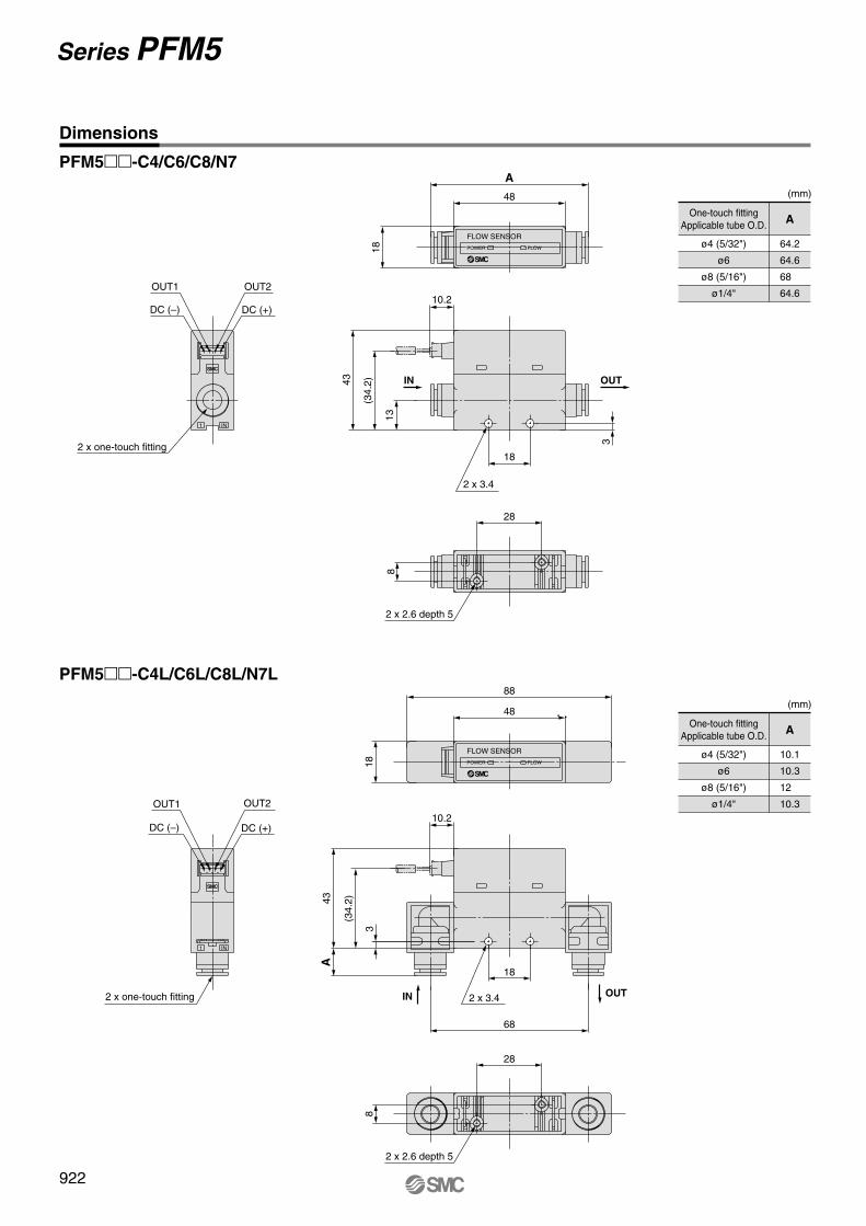
PFM5��-C4/C6/C8/N7
(mm)
One-touch fittingApplicable tube O.D.
ø4 (5/32")
ø6
ø8 (5/16")
ø1/4"
A
64.2
64.6
68
64.6
PFM5��-C4L/C6L/C8L/N7L
(mm)
One-touch fittingApplicable tube O.D.
ø4 (5/32")
ø6
ø8 (5/16")
ø1/4"
A
10.1
10.3
12
10.3
1 IN
OUT1
DC (–)
OUT2
DC (+)
2 x one-touch fitting
1 IN
2 x one-touch fitting
OUT1
DC (–)
OUT2
DC (+)
18
68
10.2
3
(34.
2)43A
2 x 3.4 OUTIN
18
10.2
43
3
13
(34.
2)
2 x 3.4
IN OUT18
48
A
FLOW SENSOR
POWER FLOW
18
48
88
FLOW SENSOR
POWER FLOW
28
8
2 x 2.6 depth 5
28
8
2 x 2.6 depth 5
Dimensions
922
Series PFM5
P0898-P0970-E.qxd 08.8.27 7:07 PM Page 922

PFM5��-(N)01/(N)02/F01
PFM5��-(N)01L/(N)02L/F01L
1 IN
2 x port size
Rc 1/8, 1/4NPT 1/8, 1/4G 1/8
DC (+)DC (–)
OUT2OUT1
2 x 3.4
18
43
13
10.2
3
(34.
2) IN OUT
1 IN
Width across flats 17
DC (+)DC (–)
OUT2OUT1
2 x port size
Rc 1/8, 1/4NPT 1/8, 1/4G 1/8
68
3
(34.
2)
18
43
10.2
13
2 x 3.4IN OUT
48
70
Wid
th a
cros
s fla
ts 1
7
18
FLOW SENSOR
POWER FLOW
88
48
18
FLOW SENSOR
POWER FLOW
28
8
2 x 2.6 depth 5
28
8
2 x 2.6 depth 5
8
Dimensions
923
2-Color Display Digital Flow Switch Series PFM5
PFM
PFMV
PF2A
PF2W
PF2D
IF
P0898-P0970-E.qxd 08.8.27 7:07 PM Page 923

924
PFM5��-F02
PFM5��-F02L
1 IN
18
OUT1
DC (–)
OUT2
DC (+)
2 x port size
G 1/418
10.2
13
(34.
2)43
3
2 x 3.4
IN OUT
1 IN
Width across flats 21
DC (+)
OUT2
2 x port sizeG 1/4
OUT1
DC (–)
18
2 x 3.4
68
1743
3
(34.
2)
10.2
IN OUT
48
78
Wid
th a
cros
s fla
ts 2
1
FLOW SENSOR
POWER FLOW
88
48
18
FLOW SENSOR
POWER FLOW
2 x 2.6 depth 5
8
28
8
28
2 x 2.6 depth 5
Dimensions
Series PFM5
P0898-P0970-E.qxd 08.8.27 7:08 PM Page 924

925
PFM5�S-C4/C6/C8/N7
(mm)
One-touch fittingApplicable tube O.D.
ø4 (5/32")
ø6
ø8 (5/16")
ø1/4"
A
92.2
92.6
96
92.6
PFM5�S-C4L/C6L/C8L/N8L(mm)
One-touch fittingApplicable tube O.D.
ø4 (5/32")
ø6
ø8 (5/16")
ø1/4"
A
10.1
10.3
12
10.3
1 IN
DC (+)DC (–)
OUT2OUT1
2 x one-touch fitting
1 IN
DC (–)
OUT1
DC (+)
OUT2
2 x one-touch fitting
51.5
(M
ax.5
8.5)
13
(34.
2)
3
10.2
43
18
2 x 3.4
IN OUT
18
48
58
76
A
FLOW SENSOR
POWER FLOW
10.2
3
(34.
2)
A43
18
68
51.5
(M
ax.5
8.5)
2 x 3.4IN OUT
18
48
58
88
FLOW SENSOR
POWER FLOW
28 20
8
3 x 2.6 depth 5
2 x 2.6 depth 5
28
8
Dimensions
2-Color Display Digital Flow Switch Series PFM5
PFM
PFMV
PF2A
PF2W
PF2D
IF
P0898-P0970-E.qxd 08.8.27 7:08 PM Page 925

926
PFM5�S-(N)01/(N)02/F01
PFM5�S-(N)01L/(N)02L/F01L
1 IN
Width across flats 17
DC (+)DC (–)
OUT2OUT1
2 x port size
Rc 1/8, 1/4NPT 1/8, 1/4G 1/8
10.2
3
(34.
2)
18
68
1343
51.5
(M
ax. 5
8.5)
2 x 3.4IN OUT
1 IN
DC (–)
OUT1 OUT2
DC (+)
2 x port size
Rc 1/8, 1/4NPT 1/8, 1/4G 1/8
18
13
(34.
2)43
10.2
51.5
(M
ax. 5
8.5)
3
2 x 3.4
IN OUT
18
48
58
76
98
Wid
th a
cros
s fla
ts 1
7
FLOW SENSOR
POWER FLOW
48
58
88
18
FLOW SENSOR
POWER FLOW
28 20
8
3 x 2.6 depth 5
2 x 2.6 depth 5
28
8
Dimensions
Series PFM5
P0898-P0970-E.qxd 08.8.27 7:08 PM Page 926

927
PFM5�S-F02
PFM5�S-F02L
1 IN
Width across flats 212 x port size
OUT2
DC (+)DC (–)
OUT1
G 1/4
51.5
(M
ax. 5
8.5)
68
2 x 3.4
181743
3
(34.
2)
10.2
IN OUT
1 IN
2 x port size
G 1/4
OUT2
DC (+)
OUT1
DC (–)
2 x 3.4
51.5
(M
ax. 5
8.5)
10.2
18
43
13
(34.
2)
3IN OUT
Wid
th a
cros
s fla
ts 2
1
106
76
58
48
18
FLOW SENSOR
POWER FLOW
18
88
58
48
FLOW SENSOR
POWER FLOW
28 20
8
3 x 2.6 depth 5
28
8
2 x 2.6 depth 5
Dimensions
2-Color Display Digital Flow Switch Series PFM5
PFM
PFMV
PF2A
PF2W
PF2D
IF
P0898-P0970-E.qxd 08.8.27 7:08 PM Page 927

928
OUT
Pan
el th
ickn
ess
1 to
3.2
42.5
3
IN
3
Pan
el th
ickn
ess
1 to
3.2
51.5
(M
ax.5
8.5)
76
A42
.53
42.5
3
Pan
el th
ickn
ess
1 to
3.2
51.5
(M
ax.5
8.5)
342
.5
Pan
el th
ickn
ess
1 to
3.2
Panel mount / Without flow adjustment valve / Straight Panel mount / With flow adjustment valve / Straight
Panel mount / Without flow adjustment valve Panel mount / With flow adjustment valve
(mm)
One-touch fittingApplicable tube O.D.
ø4 (5/32")
ø6
ø8 (5/16")
ø1/4
A
92.2
92.6
96
92.6
(mm)
One-touch fittingApplicable tube O.D.
ø4 (5/32")
ø6
ø8 (5/16")
ø1/4
A
64.2
64.6
68
64.6
78
2829.9
FLOW SENSOR
POWER FLOW
A
58
2829.9
FLOW SENSOR
POWER FLOW
29.9
28 18
88
58
FLOW SENSOR
POWER FLOW
93
78
182829.9
FLOW SENSOR
POWER FLOW
Dimensions
Note) Piping entry direction: Minimum dimensions for bottom side piping. If using straight piping, the piping material and tubing need to be taken into consideration when designing the system. If a bend (R) is used, limit it to R3 or less.
Panel Fitting Dimensions
Panel thickness 1 to 3.2 mm
Note) Piping entry direction: Minimum dimensions for bottom side piping. If using straight piping, the piping material and tubing need to be taken into consideration when designing the system. If a bend (R) is used, limit it to R3 or less.
Panel Fitting Dimensions
Panel thickness 1 to 3.2 mm
94 or more Note)
74 +0.50
34 o
r m
ore
24+
0.5
0
94 or more Note)
54 +0.50
34 o
r m
ore
24+
0.5
0
4 x R3 or less
4 x R3 or less
4 x R3 or less 4 x R3 or less
4 x R3 or less
4 x R3 or less
Series PFM5
P0898-P0970-E.qxd 08.8.27 7:08 PM Page 928

929
11IN1 IN IN
43
52.4
431.
2
48
18
1.2
51.5
(M
ax. 5
8.5)
18
4348
With bracket / Without flow adjustment valve With bracket / With flow adjustment valve
DIN rail mounting
Cable Specifications of Lead Wire with Connector
∗ Connects to the PFM3�� series.
Insulation
Finished external diameter
Nominal cross section area
Material
Construction
External diameter
Material
External diameter
Colors
Material
Color
Rated temperature
Rated voltage
Number of wires
Conductor
Sheath
80°C30 V
4
AWG26
Soft copper wire
28 / 0.08 mm
Approx. 0.50 mm
Cross-linked vinyl chloride resin compound
Approx. 1.00 mm
Brown, White, Black, Blue
Oil-resistant vinyl chloride resin compound
Light gray
ø3.5 +0.10–0.25
5 ±2
Brown
White
Black
Blue
6.5
+21–
2020+50
0
200
–5
30 ±3
Terminal semi-stripped
Lead wire with connectorZS-33-D
48
36
28
34 26 18
4 x 3.4
FLOW SENSOR
POWER FLOW
34 26 18
24 28
76
4 x 3
.4
36
FLOW SENSOR
POWER FLOW
18 x n pcs. + 34.4
18
48
FLO
W S
EN
SO
R
PO
WE
RF
LOW
FLO
W S
EN
SO
R
PO
WE
RF
LOW
FLO
W S
EN
SO
R
PO
WE
RF
LOW
Dimensions
• DIN rail (supplied by customers)• Port size, F02: G1/4 cannot be mounted on the DIN rail.
2-Color Display Digital Flow Switch Series PFM5
PFM
PFMV
PF2A
PF2W
PF2D
IF
P0898-P0970-E.qxd 08.8.27 7:08 PM Page 929

Pressure Loss (Pressure: 350 [kPa])
Flow Characteristics
PFM710, 510 / For 10 (l/min)
Pre
ssur
e lo
ss (
kPa)
0.35
0.30
0.25
0.20
0.15
0.10
0.05
Flow rate (l/min)
1 2 4 6 8 100
PFM750, 550 / For 50 (l/min)
Pre
ssur
e lo
ss (
kPa)
4
3
2
1
Flow rate (l/min)
5 10 20 30 40 500
PFM711, 511 / For 100 (l/min)
PFM725, 525 / For 25 (l/min)
Pre
ssur
e lo
ss (
kPa)
1.0
0.8
0.6
0.4
0.2
Flow rate (l/min)
5 10 15 20 250
Pre
ssur
e lo
ss (
kPa)
14
12
10
8
6
4
2
Flow rate (l/min)
10 20 40 60 80 1000
PFM725, 525 / For 25 (l/min)
PFM711, 511 / For 100 (l/min)
Series PFM7/PFM5Common Specifications
PFM710, 510 / For 10 (l/min)
PFM750, 550 / For 50 (l/min)60
40
20
05 10 150
Flo
w r
ate
(l/m
in)
Number of needle rotations
750 (kPa)
300 (kPa)
100 (kPa)
Flo
w r
ate
(l/m
in)
Number of needle rotations
120
100
80
60
40
20
5 10 150
750 (kPa)
300 (kPa)
100 (kPa)
Flo
w r
ate
(l/m
in)
Number of needle rotations
30
20
10
5 10 150
750 (kPa)
300 (kPa)
100 (kPa)
Flo
w r
ate
(l/m
in)
Number of needle rotations
15
10
5
05 10 15
750 (kPa) 300 (kPa)
100 (kPa)
930
P0898-P0970-E.qxd 08.8.27 7:08 PM Page 930

931
Parts Description
Construction
Detection Principle
2
IN
1S
Output (OUT1) indicator
Output (OUT2) indicator
Button
Button
ButtonLED display
Flow adjustment valve
Knurled lock nut
Piping port
Body
Through-hole
This MEMS sensor chip consists of upstream temperature measuring sensor (Ru) and down-stream temperature measuring sensor (Rd), which are placed symmetrically from the center of a platinum thin film coated heater (Rh) mounted on a membrane, and an ambient tempera-ture sensor (Ra) for measuring gas temperature.The principle is as shown in the diagram on the right. (a) When the gas is static, the tempera-ture distribution of heated gas centered around Rh is uniform, and Ru and Rd have the same resistance. (b) When the gas flows from the left side, it upsets the balance of the temperature distribution of heated gas, and the resistance of Rd becomes greater than that of Ru.The difference in resistance between Ru and Rd is proportional to the gas velocity, so meas-urement and analysis of the resistance can show the flow direction and velocity of the gas.Ra is used to compensate the gas and/or ambient temperature.
RaRu Rh Rd
RaRu Rh Rd
Flow
(b) The gas flows from the left side.
(a) The gas is static.
Component Parts
!1
!5 !2
!3
!6
!7
!4
q w
w
qoire uy!0 ot
PFM7
PFM5
Illuminates when the output (OUT1) is turned on.Flashes when overcurrent error occurs.
Description
Output (OUT1)indicator (Green)
Item
Illuminates when the output (OUT2) is turned on.Flashes when overcurrent error occurs.
Output (OUT2)indicator (Red)
Indicates the flow rate, set mode state and error code. The display color can be selected between red and green according to the output (OUT1) status.
LED display
Selects the operation mode and increases the set value for ON and OFF.Used to transfer to peak indication mode.
Selects the operation mode and decreases the set value for ON and OFF.Used to transfer to bottom indication mode.
Used to make changes in each mode and to enter the set value.
Reset function is activated by pressing � and � buttons simultaneously. Returns the indicated value to zero and clears errors.
Flashing interval changes according to flow rate. Flashes faster when flow rate is increased. Color changes to red when exceeding the rated flow rate.
Reset
Main body of the flow switchBody
Orifice mechanism to adjust the flow rateFlow adjustment valve
Connection port for pipingPiping port
Flow rate confirmationindicator (Green)
Used to fix the needle.Knurled lock nut
Illuminates when power is supplied.Power confirmationindicator (Green)
Button
Button
Button
Flow rate confirmation indicator (Green)
Power confirmation indicator (Green)
Fitting for piping
O-ring
O-ring
Rectifying module
Body
Sensor housing
Sensor chip
Orifice
Seal
Mesh
Bottom piping adapter
O-ring
Flow adjustment valve assembly
Body B
Needle
O-ring
O-ring
No. Description Note
1
2
3
4
5
6
7
8
9
10
11
12
13
14
15
16
17
Electroless nickel plated
Fluoro coated
Fluoro coated
Electroless nickel plated
Fluoro coated
Fluoro coated
Electroless nickel plated
Electroless nickel plated
Fluoro coated
Fluoro coated
Material
Brass
FKM
HNBR
PBT
LCP
Silicon
Brass
FKM
PBT
HNBR
PBT
Brass
Brass
HNBR
HNBR
Stainlesssteel 304
Stainlesssteel 304
2-Color Display Digital Flow Switch Series PFM7/PFM5
PFM
PFMV
PF2A
PF2W
PF2D
IF
P0898-P0970-E.qxd 08.8.27 7:08 PM Page 931

932
t u
i
u
i
y
qw
u
i
e
r
i
u
i
u
i
u
Straight piping
Bottom piping
Straight piping withflow adjustment valve
Bottom piping withflow adjustment valve
Component Parts
Body
Lead wire with connector (2 m)
IN side Bottom piping adapter (with pin)
OUT side Bottom piping adapter (with pin)
For straight pipingFlow adjustment valve assembly(with pin)
For bottom pipingFlow adjustment valve assembly(with pin)
One-touch fitting
Female thread
No. Description
ZS-33-D
ZS-33-P1L
ZS-33-P2L
ZS-33-10N
ZS-33-25N
ZS-33-50N
ZS-33-11N
ZS-33-10NL
ZS-33-25NL
ZS-33-50NL
ZS-33-11NL
ZS-33-C4
ZS-33-C6
ZS-33-C8
ZS-33-N7
ZS-33-01
ZS-33-N01
ZS-33-F01
ZS-33-02
ZS-33-N02
ZS-33-F02
For 10 l/min
For 25 l/min
For 50 l/min
For 100 l/min
For 10 l/min
For 25 l/min
For 50 l/min
For 100 l/min
ø4 (5/32")
ø6
ø8 (5/16")
ø1/4"
Rc 1/8
NPT 1/8
G 1/8
Rc 1/4
NPT 1/4
G 1/4
Model
1
2
3
4
5
6
7
8
Series PFM7/PFM5
P0898-P0970-E.qxd 08.8.27 7:08 PM Page 932

How to Order
Series PFM3Flow Sensor Monitor
Option / Part No.
Description Part no.
ZS-28-A
ZS-28-B
ZS-28-C-1
ZS-27-C
ZS-27-D
Note
With M3 x 5 l (2 pcs.)
1 pc.
With M3 x 8 l (2 pcs.)
With M3 x 8 l (2 pcs.)
Power supply / Output connector (2 m)
Bracket
Sensor connector
Panel mount adapter
Panel mount adapter + Front protective cover
PFM3 00 M
Output specification012345
2 NPN outputs + 1 to 5 V output2 NPN outputs + 4 to 20 mA output2 NPN outputs + External input Note)
2 PNP outputs + 1 to 5 V output2 PNP outputs + 4 to 20 mA output2 PNP outputs + External input Note)
With unit switching functionFixed SI unit Note)
NilM
Unit specification
Option 2NoneBracket
Nil
M3 x 5 l
Bracket
M3 x 5 l
Panel
Panel mount adapter
Front protective cover
Mountingscrew(M3 x 8 l)
Panel
Panel mount adapter
Mountingscrew(M3 x 8 l)
Option 1NonePower supply / Output connector
Nil
LPower supply / Output connectorZS-28-A
Note) Cable is not connected, but shipped together.
Option 3NoneWith sensor connector
Nil
FSensor connector(e-con connector)ZS-28-C-1
Note) Connector is not connected, but shipped together.
Note) Options are not assembled, but shipped together.
Panel mount adapter
Panel mount adapter + Front protective cover
E
B
D
L
Calibration certificateNone
With calibration certificateNilA
∗ The certificate is written in English and Japanese. Other languages are available as specials.
Instruction manualWith instruction manual (Leaflet: Japanese and English)
NoneNilN
TypeRemote display unit3
Input specificationSymbol
01
ContentVoltage inputCurrent input
Applicable remote type sensor unitPFM5��(S)-�-1-�PFM5��(S)-�-2-�
Note) User can select from accumulated value external reset, auto-shift and auto-shift zero.
Note) Fixed unit: Real-time flow rate: l/minAccumulated flow: l
®
933
PFM
PFMV
PF2A
PF2W
PF2D
IF
P0898-P0970-E.qxd 08.8.27 7:08 PM Page 933

934
Analog Output Note: Analog output at maximum rated flow rate when CO2 is selected is 3 [V] for the voltage output type and 12 [mA] for the current output type.
1
0Max. rated flow value Max. rated flow value
5
1 to 5 VDC
0
4
0
20
4 to 20 mADC
0
0.2 to 10 l/min
0.5 to 25 l/min
1 to 50 l/min
2 to 100 l/min
Rated flow rangeMax. rated flow value
[l/min]
10 (5)
25 (12.5)
50 (25)
100 (50)
Note 1) Select the sensor to connect in the initial setting. If CO2 is selected as the operating fluid, the value is 1/2 on the maximum side.Note 2) When 10 l/min with a minimum unit setting of 0.01 l/min is selected for the connected sensor, the upper limit of the display range is 10.50 l/min.
When 100 l/min with a minimum unit setting of 0.1 l/min is selected for the connected sensor, the upper limit of the display range is 105.0 l/min.The setting at the time of shipment is 10 l/min with a minimum unit setting of 0.1 l/min for the connected sensor.
Note 3) When equipped with a unit switching function. (The SI unit (l/min or l) is fixed for types with no unit switching function.)Note 4) The accumulated flow value is cleared to 0 when power is turned off. It is possible to select function that holds the accumulated flow value so it is not cleared. (The accumulated flow
value can be held at 2- or 5-minute intervals.) The service life of the memory element (electronic component) is limited to 1 million overwrite cycles (assuming 24-hour operation, 5 minutes x 1 million cycles = 5 million minutes = 9.5 years) when 5-minute intervals are selected. Therefore, when using the holding function, calculate the service life based on the usage conditions, and use the switch within the service life. Applies to models equipped with a unit switching function. (The SI unit (l/min or l) is fixed for types with no unit switching function.)
Note 5) Set to hystresis mode at the time of shipment from the factory. Can be changed to window comparator mode using push-buttons.Note 6) Accumulated external reset function at the time of shipment from the factory. Auto-shift or auto-shift zero function can be selected using push-buttons.
Model PFM3��
Hysteresis Note 5)
Switch output
Analog output
Display accuracy
Display method
Status LED’s
External input Note 6)
Enclosure
Operating temperature range
Operating humidity range
Withstand voltage
Insulation resistance
Vibration resistance
Impact resistance
Temperature characteristics
Connection
Material
Mass
Accumulated pulse output
Response time
Repeatability
Real-time flow rate l/min, CFM x 10-2
Accumulated flow l, ft3 x 10-1
1999999 l
24 VDC (ripple ± 10% or less) (With polarity protection)
50 mA or less
Hysteresis mode: Variable, Window comparator mode: Variable
NPN or PNP open collector output (Same as switch output)
1 s (50 ms, 0.5 s, 2 s can be selected.)
±0.1%F.S. or less, Analog output accuracy: ±0.3%F.S. or less
±0.5%F.S. ± 1 digit or less
3+1/2-digit, 7-segment LED 2-color display (Red/Green) Sampling cycle: 10 times/sec
OUT1: Illuminates when output is turned ON (Green). OUT2: Illuminates when output is turned ON (Red).
No-voltage input (Reed or Solid state), LOW level input 30 msec or more, LOW level 0.4 V or less
IP40
Operating: 0 to 50°C Stored: –10 to 60°C (with no freezing and condensation)
Operating, Stored: 35 to 85%R.H. (with no condensation)
1000 VAC for 1 min. between whole charging part and live part
50 MΩ or more (500 VDC Mega) between whole charging part and live part
10 to 150 Hz with a 1.5 mm amplitude or 98 m/s2 acceleration, in each X, Y, Z direction for 2 hrs, whichever is smaller. (de-energized)
100 m/s2 in X, Y, Z directions 3 times each(de-energized)
±0.5%F.S. or less (based on 25°C)
Power supply / Output connection: 5P connector, Sensor connection: 4P connector
Front case, Rear case: PBT
30 g (Without cable) 85 g (With cable)
PFM30�: Voltage input 1 to 5 VDC (input impedance: 1 MΩ)PFM31�: Current input 4 to 20 mADC (input impedance: 250 Ω)
NPN or PNP open collector output: 2 outputsMaximum load current: 80 mA, max. load voltage 30 VDC (at NPN output),
Residual voltage 1 V or less (at load current 80 mA), With short-circuit protection
Voltage output: 1 to 5 VDC (0 l/min to max. rated flow rate value)Output impedance: Approx. 1 kΩ, Accuracy: ±1%F.S. or less (relative to display value)
Current output: 4 to 20 mADC (0 l/min to max. rated flow rate value)Max. load impedance: 600 Ω (at 24 VDC), Min. load impedance: 50 Ω
Accuracy: ±1%F.S. or less (relative to display value)
0.01 l/min
0.1 l/pulse
0.1 l/min
0.1 l/pulse
0.1 l/min
0.1 l/pulse
0.1 l/min
1 l/pulse
Minimum unit setting Note 2)
Accumulated pulse flow rate exchange value
Indication unit Note 3)
Accumulated flow range Note 4)
Power supply voltage
Current consumption
Sensor inputNumber of inputs: 1
∗ ( ): Fluid: CO2
Rated flow range(Flow rate range)
Dry air, N2, Ar
CO2
Displayable range
Settable range Note 1)
Dry air, N2, Ar
CO2
Dry air, N2, Ar
CO2
0.2 to 10 l/min
0.2 to 5 l/min
0.2 to 10.5 l/min
0.2 to 5.2 l/min
0 to 10.5 l/min
0 to 5.2 l/min
0.5 to 25 l/min
0.5 to 12.5 l/min
0.5 to 26.3 l/min
0.5 to 13.1 l/min
0 to 26.3 l/min
0 to 13.1 l/min
1 to 50 l/min
1 to 25 l/min
1 to 52.5 l/min
1 to 26.2 l/min
0 to 52.5 l/min
0 to 26.2 l/min
2 to 100 l/min
2 to 50 l/min
2 to 105 l/min
2 to 52 l/min
0 to 105 l/min
0 to 52 l/min
Specifications
Ana
log
outp
ut [V
]
Ana
log
outp
ut [m
A]
Note 1)
Series PFM3
P0898-P0970-E.qxd 08.8.27 7:08 PM Page 934

Internal Circuits
DC (+)
24 VDC
+
–
(Brown)Auto-shift input
(Gray)
(Black)
(White)
(Blue)
OUT1
OUT2
DC (–)
DC (+)
24 VDC
+
–
(Brown)
(Gray)
(Black)
(White)
(Blue)
OUT1
OUT2
DC (–)
Auto-shift input
DC (+)
24 VDC
+
–
(Brown)Analog output
(Gray)
(Black)
(White)
(Blue)
OUT1
OUT2
DC (–)
DC (+)
(Brown)Analog output
(Gray)
(Black)
(White)
(Blue)
OUT1
OUT2
DC (–)
24 VDC
+
–
PFM3�0NPN open collector output: 2 outputsMax. 30 V, 80 mA, residual voltage 1 V or lessAnalog output: 1 to 5 VOutput impedance: approx. 1 kΩ
PFM3�3PNP open collector output: 2 outputsMax. 80 mA, residual voltage 1 V or lessAnalog output: 1 to 5 VOutput impedance: approx. 1 kΩ
PFM3�1NPN open collector output: 2 outputsMax. 30 V, 80 mA, residual voltage 1 V or lessAnalog output: 4 to 20 mAMax. load impedance: 300 Ω (12 VDC) 600 Ω (24 VDC)Min. load impedance: 50 Ω
PFM3�4PNP open collector output: 2 outputsMax. 80 mA, residual voltage 1 V or lessAnalog output: 4 to 20 mAMax. load impedance: 300 Ω (12 VDC) 600 Ω (24 VDC)Min. load impedance: 50 Ω
PFM3�2NPN open collector output with external input: 2 outputsMax. 30 V, 80 mA, residual voltage 1 V or less
PFM3�5PNP open collector output with external input: 2 outputsMax. 80 mA, residual voltage 1 V or less
DC (+)
24 VDC
+
–
(Brown)Analog output
(Gray)
(Black)
(White)
(Blue)
OUT1
OUT2
DC (–)
DC (+)
(Brown)Analog output
(Gray)
(Black)
(White)
(Blue)
OUT1
OUT2
DC (–)
24 VDC
+
–
Accumulated pulse output wiring example
PFM3�0PFM3�1PFM3�2
Black OUT1
White OUT2
Blue DC (–)
Max. 30 V, 80 mA
50 msec
0 V
50 msec
or
50 msec
0 V
50 msec
or
Max. 80 mA
Brown DC (+)
Black OUT1
White OUT2
PFM3�3PFM3�4PFM3�5
Load
Load
Load
Load
Load
Load
Load
Load
Load
Load
Load Load
Load
Load
Load
Load
Load
Load
Load
Load
Mai
n ci
rcui
t
Mai
n ci
rcui
t
Mai
n ci
rcui
t
Mai
n ci
rcui
t
Mai
n ci
rcui
t
Mai
n ci
rcui
t
Flow Sensor Monitor Series PFM3
935
PFM
PFMV
PF2A
PF2W
PF2D
IF
P0898-P0970-E.qxd 08.8.27 7:08 PM Page 935

936
Shows the current flow rate, mode setting, selected display unit, and error code. Four display modes are available, some of which use indications that are fixed either red or green, and others use indications that change from green to red.
Used for mode selection and increasing the ON/OFF setting value. Also used to switch to peak display mode.
Used to activate mode changes and new setting val-ues.
Used for mode selection and decreasing the ON/OFF setting value. Also used to switch to bottom display mode.
LCD Display
Lights when the output (OUT1) is turned on.
Output (OUT1) Indicator (Green)
� Button
Lights when the output (OUT2) is turned on.
Output (OUT2) Indicator (Red)
SET Button
� Button
Descriptions
Series PFM3
P0898-P0970-E.qxd 08.8.27 7:08 PM Page 936

937
Dimensions
1.5
Thread depth 42 x M3 x 0.5
20 ± 0.1
8.2
3.21.5
331
Power supply / Output connector
Sensor connector
1.6
40
Bracket
26.5
30
20
31.5
A
41View A
4.2
10
15
46
22
35
7.2
With bracket
With panel mount adapter With panel mount adapter + Front protective cover
Sensor connector (ZS-28-C-1)
42.4
Panel mount adapter + Front protective cover
�34.5 2411
Panel mount adapter
�34.5 247
8.75
Panel thickness dimension: 0.5 to 6
Pin no.1234
Terminal nameDC (+)N.C.
DC (–)IN∗
�30
10
∗ 1 to 5 V or 4 to 20 mA
Flow Sensor Monitor Series PFM3
PFM
PFMV
PF2A
PF2W
PF2D
IF
P0898-P0970-E.qxd 08.8.27 7:08 PM Page 937

938
Panel fitting dimensions
1 pc.
Secure mounting of n (2 or more) switches (horizontal)
Secure mounting of n (2 or more) switches (vertical)
31 0–0.4 31 x n pcs. + 3.5 x (n pcs. – 1)
24 o
r m
ore
310 –0
.4
310 –0
.4
31 x
n p
cs. +
3.5
x (
n pc
s. –
1)
24 or more 31 0–0.4
Cable SpecificationsRated temperature
Rated voltage
Number of wires
Con-ductor
Sheath
Finished external diameter
Nominal cross section area
Material
Construction
External diameter
Material
External diameter
Standard thickness
Colors
Material
Standard thickness
Color
105°C300 V
5
0.2 mm2
Soft copper wire
40 / 0.08 mm
0.58 mm
Cross-linked vinyl chloride resin compound
Approx. 1.12 mm
0.27 mm
Brown, Black, White, Gray, Blue
Oil-resistant vinyl chloride resin compound
0.5 mm
Light gray (Munsell N7)
ø4.1
Insula-tion
DC (+) Brown 5
OUT1 Black 4
OUT2 White 3
Analog output orauto-shift input Gray 2
DC (–) Blue 120
2020
Power supply / Output connector (ZS-28-A)
4 x R2 or less 4 x R2 or less
4 x R2 or less
Note) If a bend (R) is used, limit it to R2 or less.
Dimensions
Series PFM3
P0898-P0970-E.qxd 08.8.27 7:08 PM Page 938

Series PFMFunction Details
� Indication colorThe indication color can be selected for each output condition. The selection of the indication color provides visual iden-tification of abnormal values. (The indi-cation color depends on OUT1 setting.)
� Selection of operating fluidThe fluid can be selected. If argon (Ar) or carbon dioxide (CO2) is used, the setting needs to be changed.Note) When CO2 is selected, the upper limit of the meas-ured flow rate range will be 1/2 of that for other fluids.
� Indication modeThe indication mode can be selec-ted between real-time flow rate and accumulated flow.
Real-time flow rate display
Accumulated flow display
Dry air, N2
Argon
CO2
Green for ON, Red for OFF
Red for ON, Green for OFF
Red all the time
Green all the time
0.05 sec.
0.5 sec.
1 sec.
2 sec.
� Setting of response timeThe flow rate may change momentarily during transition between ON (open) and OFF (closed) of the valve. It can be set so that this momentary change is not detected. <Principle>When the switch has been in ON area for a set period of time, the output will turn on (or off).
Standard conditions: Flow rate converted to a volume at 20°C and 1atm (atmosphere)
Normal conditions: Flow rate converted to a volume at 0°C and 1atm (atmosphere)
If the error or abnormality cannot be solved by the action above, please contact SMC for further investigation.
Description Contents Action
Flow rate error
The flow rate exceeds the up-per limit of indicated flow rate range.
Decrease the flow rate.
There is a reverse flow equiv-alent to –5% or more.
Turn the flow to correct direction.
Overcurrenterror
System error
Zero clear error
Flow rate error
Load current of 80 mA or more is applied to the switch output (OUT1).
Possibility of internal circuit damage before factory adjust-ment.
Stop operation imme-diately and contact SMC.
System error. Possibility of data memorizing failure or in-ternal circuit damage.
Reset the unit, and carry out all settings again.
Load current of 80 mA or more is applied to the switch output (OUT2).
Eliminate the cause of the overcurrent by turn-ing off the power supply and then turn on it again.
Perform zero clear of ac-cumulated flow rate when there is no flow.
If zero clear is performed (by holding down and but-tons simultaneously for 1 sec.) while there is some flow, “Er4” will be displayed for 1 sec.
The flow rate exceeds the ac-cumulated flow rate range.
Clear the accumulated flow rate. (This error does not matter when the accumulated flow rate is not being used.)
� Selection of indication unit referenceThe indication unit reference can be selected between standard conditions and normal conditions.
� External input functionThe external input function can be selected from accumulated value external reset, auto-shift and auto-shift zero.(Input signal: Connect input line to GND for 30 ms or more.)External reset: This function resets the accumulated value to “0”
when an input signal is applied.Auto-shift: This function generates an output corresponding
to the change in relation to real-time flow rate when an input signal is applied.
Auto-shift zero: This function displays real-time flow rate as “0” when a positive input signal is applied in the auto shift function described above.
Set values and flow rates that are relatively on the negative side are expressed by illumination of the decimal point on the far left.
� Indication resolutionThe indication resolution of the PFM710 and 711 series can be changed to enable values to be indicated in smaller steps.
� Accumulated value holdAccumulated value is not cleared even when the power supply is turned off.The accumulated value is memorized every 2 or 5 min. during measurement, and continues from the last memorized value when the power supply is turned on again. The life time of the memory element is 1 million access cycles. Take this into consideration before using this function.
100 resolutionPFM710 by 0.1 l/minPFM711 by 1 l/min
1000 resolutionPFM710 by 0.01 l/minPFM711 by 0.1 l/min
� Output operationThe output operation can be selected from the following:Output (hysteresis mode and window comparator mode) corre-sponding to real-time flow rate,Output corresponding to accumulated flow,Accumulated output pulse outputAt the time of shipment from the factory, it is set to hysteresis mode and normal output.
� Error indication functionWhen an error or abnormality arises, the location and contents are displayed.
� Peak/Bottom value indicationThe maximum (minimum) flow rate is detected and updated from when the power supply is turned on. In peak (bottom) value indi-cation mode, this maximum (minimum) flow rate is displayed.
� Keylock functionPrevents operation errors such as accidentally changing setting values.
� Zero clear functionAllows the user to adjust the measured flow rate indication to zero. The adjustment range is ±7%F.S. of the initial factory setting.
� Setting of secret codeThe user can select whether a secret code must be entered to re-lease key lock.At the time of shipment from the factory, it is set such that the se-cret code is not required.
� Selection of power-saving modeThe power-saving mode can be selected.With this function, if no buttons are pressed for 30 sec., it shifts to power-saving mode.At the time of shipment from the factory, the product is set to the normal mode (the power-saving mode is turned off).(When power-saving mode is activated, the decimal point flashes.)
� Selection of analog output filterThis selection is available when using a product with an analog output.A signal with fast response speed can be generated by turning off the analog output filter.
939
PFM
PFMV
PF2A
PF2W
PF2D
IF
P0898-P0970-E.qxd 08.8.27 7:08 PM Page 939

Series PFM7/PFM5Made to Order 1Please contact SMC for detailed specifications, lead times and prices.
Changing the piping entry direction combination for IN and OUT side
Dimensions
PFM ��-C4/C6/C8/N7-�-X694
PFM ��-�01/02-�-X693 PFM ��-�01/02-�-X694
PFM 7 X693
Piping entry directionNote) No symbol is entered. IN side: Straight / OUT side: Bottom
IN side: Bottom / OUT side: StraightX693X694
Changing the piping entry direction combination
Remote sensor unitIntegrated display
57
Type
IN
2 x 3.4
13
A43
1
(34.
2)
3
OUT
B
18
4820
10.2
IN
OUT2 x 3.4
10.2
143
(34.
2)13
3
B 48 20
18
A
IN
OUT
2 x 3.4
C
A
2048
18
B
3
13
(34.
2)431
10.2
OUT
2 x 3.4
B48
18
20IN
13
3A43
(34.
2)
1
10.2
C
One-touch fittingApplicable tube O.D.
C4
C6
C8
N7
ø4 (5/32")
ø6
ø8 (5/16")
ø1/4
A
10.1
10.3
12
10.3
B
8.1
8.3
10
8.3
Port size
Rc 1/8, 1/4NPT 1/8, 1/4
G 1/8
G 1/4
A
13
17
B
11
15
C(Width across flats)
17
21
PFM ��-C4/C6/C8/N7-�-X69375
75
75
75
For details of How to Order,refer to page 906 and 918.
X693, X694Symbol
940
P0898-P0970-E.qxd 08.8.27 7:08 PM Page 940

Dimensions
PFM ��S-C4/C6/C8/N7-�-X693 PFM ��S-C4/C6/C8/N7-�-X694
PFM ��S-�01/02-�-X693 PFM ��S-�01/02-�-X694
OUT
IN
2 x 3.4
51.5
(M
ax. 5
8.5)
13
B4820
18
3(3
4.2)43
1A
10.2
OUT
IN
2 x 3.4
A51
.5 (
Max
. 58.
5)
2048
18
B
3
13
(34.
2)431
10.2
One-touch fittingApplicable tube O.D.
ø4 (5/32")
ø6
ø8 (5/16")
ø1/4
A
10.1
10.3
12
10.3
B
8.1
8.3
10
8.3
One-touch fittingApplicable tube O.D.
ø4 (5/32")
ø6
ø8 (5/16")
ø1/4
A
10.1
10.3
12
10.3
B
36.1
36.3
37
36.3
Port size
Rc 1/8, 1/4NPT 1/8, 1/4
G 1/8
G 1/4
A
13
17
B
11
15
C(Width across flats)
17
21
Port size
Rc 1/8, 1/4NPT 1/8, 1/4
G 1/8
G 1/4
A
13
17
B
39
43
C(Width across flats)
17
21
IN
OUT
2 x 3.4
51.5
(M
ax. 5
8.5)
13
B4820
18
3
(34.
2)431
A
10.2
C
OUT
IN
2 x 3.4
A51
.5 (
Max
. 58.
5)
2048B
18
3
13
(34.
2)431
10.2
C
75
75
75
75
Series PFM7/PFM5Made to Order 2Please contact SMC for detailed specifications, lead times and prices.
941
PFM
PFMV
PF2A
PF2W
PF2D
IF
P0898-P0970-E.qxd 08.8.27 7:08 PM Page 941

Compatibility with argon (Ar) and carbon dioxide (CO2) mixed gas
PFM 7 X731
Integrated display7
X731Symbol
The argon–carbon dioxide gas ratio (Ar: CO2) can be selected using the push-buttons from among the following: 92 : 8, 90 : 10, 80 : 20, 70 : 30, and 60 : 40. Dimensions are same as those of standard models.
Gas ratioModel
PFM710
Rated flow range Displayable rangeAr
92%
90%
80%
70%
60%
92%
90%
80%
70%
60%
92%
90%
80%
70%
60%
92%
90%
80%
70%
60%
8%
10%
20%
30%
40%
8%
10%
20%
30%
40%
8%
10%
20%
30%
40%
8%
10%
20%
30%
40%
0.2 to 7.0 l/min
0.5 to 25.0 l/min
0.5 to 20.0 l/min
1.0 to 50.0 l/min
1.0 to 40.0 l/min
2 to 100 l/min
2 to 90 l/min
2 to 80 l/min
0.2 to 7.4 l/min
0.5 to 26.3 l/min
0.5 to 21.0 l/min
1.0 to 52.5 l/min
1.0 to 42.0 l/min
2 to 105 l/min
2 to 95 l/min
2 to 84 l/min
PFM725
PFM750
PFM711
CO2Settable range
Max. analog output
Voltage (Vmax) Current (Imax)
0 to 7.4 l/min
0 to 26.3 l/min
0 to 21.0 l/min
0 to 52.5 l/min
0 to 42.0 l/min
0 to 105 l/min
0 to 95 l/min
0 to 84 l/min
3.80 V
5.00 V
4.20 V
5.00 V
4.20 V
5.00 V
4.60 V
4.20 V
15.2 mA
20.0 mA
16.8 mA
20.0 mA
16.8 mA
20.0 mA
18.4 mA
16.8 mA
Analog voltage output (1 to 5 V)
5
Vmax
1
00 0
When dry air selectedMax. rated flow value
When mixed gas selectedMax. rated flow value
Analog current output (4 to 20 mA)
20
Imax
4
0
When dry air selectedMax. rated flow value
When mixed gas selectedMax. rated flow value
Output characteristics using mixed gas
Series PFM7/PFM5Made to Order 3Please contact SMC for detailed specifications, lead times and prices.
For details of How to Order,refer to page 906 and 918.
Ana
log
outp
ut [V
]
Ana
log
outp
ut [m
A]
942
P0898-P0970-E.qxd 08.8.27 7:08 PM Page 942

Design and Selection
Mounting
Warning1. Monitor the flow direction of the fluid.
Install and connect piping so that fluid flows in the direction of the arrow indicated on the body.
2. Remove dirt and dust from inside of the piping by means of air blow, before attaching to the switch.
3. Do not drop or bump.Do not drop, bump, or apply excessive impacts (490 m/s2) while handling. Although the external body of a switch (switch case) may not be damaged, the switch inside could be damaged and cause a malfunction.
4. Hold the body of the switch when handling.The tensile strength of the cord is 49 N and applying a greater pulling force than this can cause a malfunction. When handling, hold the body of the switch.
5. Do not use until you can verify that equipment can operate properly.Following mounting, repair, or retrofit, verify correct mounting by conducting suitable function and leakage tests after piping and power connections have been made.
6. Never mount the switch in a place that will be used as a scaffold during piping.
7. Apply a wrench only to the metal part of the piping when installing the flow switch in the system piping.There is a risk of breakage of the switch.
1. Operate the switch only within the specified voltage.Use of the switch outside of the specified voltage range can cause not only a malfunction and damage to the switch, but it can also cause electrocution and fire.
2. Do not exceed the maximum allowable load specification.A load exceeding the maximum load specification can cause damage to the switch.
3. Do not use a load that generates surge vol-tage.Although surge protectiion is installed in the circuit at the output side of the switch, damage may still occur if a surge is applied repeatedly. When working directly such an unit as relay, sole-noid valve, etc., which generates surge, use a built-in surge ab-sorbing element type.
4. Be sure to verify the applicable fluid.The switches do not have an explosion proof rating. To prevent possible fire hazard, do not use with flammable gases or fluids.
5. Monitor the internal voltage drop of a switch.When operating below the specified voltage, it is possible that a load may be ineffective, even though the pressure switch func-tion is normal. Therefore, the formula below should be satisfied after confirming the voltage of the load.
6. Use the switch within the specified flow rate measurement and operating pressure.Operating beyond the specified flow rate and operating pres-sure can damage the switch.
7. Never use flammable fluids and/or permeable fluids.They may cause a fire, an explosion or corrosion.∗ Refer to the MSDS (Material Safety Data Sheet) when using
chemicals.
8. To prevent damage due to failure and/or mal-function of the product, establish a backup system such as a fail-safe system which en-ables multiple-stage type operation of the equipment and machinery.
9. When the product is for an interlock circuit, the following points should be noted.• Provide double interlocking through another system (mechan-
ical protection function, etc.).• Perform checks to ensure the product is operating properly,
as there is a risk of injury.
Warning Caution1. Ensure sufficient space for maintenance ac-
tivities.Provide space required for maintenance.
2. The direct-current power supply to combine should be UL authorized power supply.
3. Data of the switch are stored even after the power supply is turned off.Input data is stored in an EEPROM so that the data will not be lost after the flow switch is turned off. (The data can be rewritten for up to one million times, and stored for up to 20 years.)
No load voltage (V peak)
0 to 20 [V]
Above 20 to 30 [V]
Max. current rating
5.0
100
Peak voltage
(1) Limited voltage current circuit in accordance with UL 508.A circuit in which power is supplied by the secondary coil of a transformer that meets the following conditions.• Maximum voltage (with no load):
30 Vrms (42.4 V peak) or less• Maximum current:
(1) 8 A or less (including when short circuited)(2) limited by circuit protector (such as fuse) with the follow-
ing ratings.
(2) A circuit using max. 30 Vrms or less (42.4 V peak), which is powered by UL 1310 compatible Class-2 power supply or UL 1585 compatible Class-2 transformer (Class-2 circuit).
Series PFMSpecific Product Precautions 1Be sure to read before handling.Refer to front matters 58 and 59 for Safety Instructions and pages 892 to 896 for Flow Switch Precautions.
Supplyvoltage
– >Internal voltagedrop of switch
Minimum operatingvoltage of load
943
PFM
PFMV
PF2A
PF2W
PF2D
IF
P0898-P0970-E.qxd 08.8.27 7:08 PM Page 943

4. When fixing the switch with screws using mounting holes, use a tightening torque of 0.3 N·m or less. If necessary, tighten the product to prevent it from loosening.
Operating Environment
1. Never use in the presence of explosive gases.The switch does not have an explosion proof construction. If it is used in an environment where explosive gases are used, it may cause an explosive disaster. Therefore, never use it in such an environment.
2. Mount the switch in a location where there is no vibration greater than 98 m/s2, or no im-pact greater than 490 m/s2.With a switch with orifice, the adjusted flow rate value could be affected by vibration.
3. Do not use in an area where surges are generated.When there are units that generate a large amount of surge in the area around a pressure switch, (e.g., solenoid type lifters, high frequency induction furnaces, motors, etc.) this may cause deterioration or damage to the switch’s internal circuitry. Avoid sources of surge generation and crossed lines.
4. Switches are not equipped with surge protec-tion against lightning.The flow switches are CE compliant; however, they are not equipped with surge protection against lightning. Lightning surge protection measures should be applied directly to system components as necessary.
5. Avoid using the switch in an environment where the likelihood of splashing or spraying of liquids exists.The switch is an open type and should not be used in an envir-onment exposed to splashing of water and oil.
6. Do not use the product in an environment subject to a temperature cycle.If the product is subject to a temperature cycle other than natu-ral changes in air temperature, the internal components of the switch could be adversely affected.
7. Do not mount the product in locations where it is exposed to radiant heat.This could result in damage and/or malfunction.
Warning
1. Verify the color and the terminal number when wiring.Incorrect wiring can cause the switch to be damaged and malfunction. Verify the color and the terminal number in the instruction manual when wiring.
2. Use caution not to repeatedly apply bending or stretching forces to the lead wire.Repeated pulling or bending of the lead wire may cause some of the wires to break.
Wiring
Warning
3. Confirm proper insulation of wiring.Make sure that there is no faulty wiring insulation (contact with other circuits, ground fault, improper insulation between terminals, etc.). Damage may occur due to excess current flow into a switch.
4. Do not wire in conjunction with power lines or high voltage lines.Wire separately from power lines and high voltage lines, and avoid wiring in the same conduit with these lines. Control circuits, including switches, may malfunction due to noise from these lines.
5. Do not short-circuit a load.Although the switch displays an overcurrent error if a load is short-circuited, there is not protection against incorrect wiring (power source polarity, etc.). Use caution to avoid wiring incorrectly.
6. Do not connect wiring while energizing the product.The switch and any equipment connected to it could break and malfunction.
Wiring
WarningMounting
1. Observe the proper tightening torque.When the switch is tightened beyond the specified tightening torque, the switch may be damaged.
2. Do not mount the switch in a place that will be used as a scaffold.The switch could break if subjected to excessive load such as being accidentally stepped on.
3. Use a tapping screw (P-tite) with nominal diameter of 3 to mount the product by using the bracket mounting hole(s) at the bottom.The length of the screw depends on the thickness of the plate to be fixed. Please select a screw whose length is the thickness of the plate + 4.8 mm. (The hole depth is 5 mm.)
Caution
Series PFMSpecific Product Precautions 2Be sure to read before handling.Refer to front matters 58 and 59 for Safety Instructions and pages 892 to 896 for Flow Switch Precautions.
944
P0898-P0970-E.qxd 08.8.27 7:08 PM Page 944

Others
Warning1. After the power is turned on, the switch’s out-
put remains off while a message is displayed. Therefore, start the measurement after a val-ue is displayed.
2. Perform settings after stopping control sys-tems.Operation reflects the new values when settings are made. However, if the power is turned OFF in that state, the settings return to the values before the change when the power is turned ON again. Make sure to press the S button to save any setting changes before turning OFF the power.
Dryer
IDFIDU
AF ARIR
AMDAFD
PFM
Airfilter
Regulator Micro mistseparator
Flowswitch
<Vacuum line>
Suction filter
ZFSFD100
PFM
Flow switch
Vacuum line
Fluid
1. Check regulators and flow adjustment valves before introducing the fluid.If pressure or flow rate beyond the specified range are applied to the switch, the sensor unit may be damaged.
2. Install a filter on the inlet side when there is a possibility of foreign matter being mixed with the fluid.
3. Use dry air of quality compliant with JIS B 8392-1 1.1.2 to 1.6.2: 2003 for this product.If any mist or drainage present in the air attaches to the product, accurate measurement could be prevented. Also, the accuracy of the product could be degraded.
Warning
Recommended air circuits<Compressed air line>
1. Do not wipe the product with chemicals such as benzene or thinner.Such chemicals could damage the product.
2. The accuracy could change by 2 to 3% when the piping is removed or replaced.The repeatability accuracy is ±1% F.S. when piping is replaced with piping of the same size. However, the accuracy could change by 2 to 3% if the size is different or when changing from straight to elbow or from elbow to straight piping.
3. Do not poke the inside of the piping port with a stick. The rectifier could break, making the product unable to sustain the desired performance.
4. Do not touch terminals or connectors when energizing the product.It could cause electric shock, malfunction, or damage to the switch.
Caution
Maintenance
1. Perform periodical inspections to ensure proper operation of the switch.Unexpected malfunctions may cause possible danger.
2. Take precautions when using the switch for an interlock circuit.When a pressure switch is used for the interlock circuit, devise a multiple interlock system to prevent trouble or malfunction, and verify the operation of the switch and interlock function on a reg-ular basis.
3. Do not make any modifications (including ex-changing the printed circuit boards) to the product.It may cause human injuries and damage.
4. When maintenance work is performed, the following points should be noted.• Turn off the power supply.• Cut off the fluid supply, drain the fluid from the piping and en-
sure the fluid is released to atmosphere before carrying out maintenance. Otherwise, it could cause injury.
Warning
Series PFMSpecific Product Precautions 3Be sure to read before handling.Refer to front matters 58 and 59 for Safety Instructions and pages 892 to 896 for Flow Switch Precautions.
945
PFM
PFMV
PF2A
PF2W
PF2D
IF
P0898-P0970-E.qxd 08.8.27 7:08 PM Page 945

CautionSettable Range and Rated Flow Range
Set the flow rate within the rated flow range.The settable rate range is the range of flow rate that can be set in the switch.The rated flow range is the range that satisfies the switch specifications (accuracy, linearity etc.).It is possible to set a value outside of the rated flow range if it is within the settable range, however, the specification is not be guaranteed.The flow range if using CO2 is given in brackets.
Rated flow range
Settable range
Displayable range
Sensor0.2 l/min 0.5 l/min 1 l/min 2 l/min 10 l/min 25 l/min 50 l/min 100 l/min
Flow range
PFM710PFM510
PFM725PFM525
PFM750PFM550
PFM711PFM511
0.2 l/min
0
0
0
0
0.5 l/min
1 l/min
2 l/min100 l/min(50 l/min)
2 l/min 105 l/min(52 l/min)
105 l/min(52 l/min)
50 l/min (25 l/min)
1 l/min 52.5 l/min (26.2 l/min)
52.5 l/min (26.2 l/min)
10 l/min (5 l/min)
0.2 l/min 10.5 l/min (5.2 l/min)
10.5 l/min (5.2 l/min)
25 l/min (12.5 l/min)
0.5 l/min 26.3 l/min (13.1 l/min)
26.3 l/min (13.1 l/min)
In the case of the PFM5 series, the displayable and settable ranges are the same as the PFM3 series flow monitor.
Series PFMSpecific Product Precautions 4Be sure to read before handling.Refer to front matters 58 and 59 for Safety Instructions and pages 892 to 896 for Flow Switch Precautions.
946
P0898-P0970-E.qxd 08.8.27 7:08 PM Page 946

![Suction verification of very small work piecesca01.smcworld.com/catalog/en/switch_sensor/PFMV-E/6-8-p0287-03… · (Vacuum pump) P2 [kPa] P2 [kPa] 5.0 4.5 4.0 3.5 3.0 2.5 2.0 1.5](https://static.fdocuments.in/doc/165x107/608a17d6a0fc58763e26eff3/suction-verification-of-very-small-work-vacuum-pump-p2-kpa-p2-kpa-50-45.jpg)