Digital Flow Switch PF2W
13
How to Order Port size Flow rate range 04 20 40 11 0.5 to 4 L/min 2 to 16 L/min 5 to 40 L/min 10 to 100 L/min Nil N F Rc NPT G Thread type Symbol 03 04 06 10 3/8 1/2 3/4 1 4 16 40 100 Port size Applicable model Flow rate (L /min) PF2W504, PF2W520 PF2W520, PF2W540 PF2W540, PF2W511 PF2W511 Remote Type Sensor Unit Measured fluid Detection type Rated flow range Operating pressure range Withstand pressure Operating fluid temperature Accuracy Note 1) Repeatability Note 1) Temperature characteristics Power supply voltage Current consumption (No load) Weight Note 3) Port size (Rc, NPT, G) PF2W504 Model PF2W520 PF2W540 PF2W511 Water Karman vortex 0 to 1 MPa 1.5 MPa ±2% F.S. (15 to 35°C, 25°C reference), ±3% F.S. (0 to 50°C, 25°C reference) Pulse output, N channel, open drain, output for monitor unit PF2W3. (Specifications: Maximum load current of 10 mA; Maximum applied voltage of 30 V) Voltage output 1 to 5 V Accuracy: ±5%F.S., Min. load impedance: 100 kΩ (Output impedance: 1 kΩ) Current output 4 to 20 mA Accuracy: ±5%F.S., Max. load impedance: 300 Ω or less (at 12 VDC), 600 Ω or less (at 24 VDC) 12 to 24 VDC ±10% 20 mA or less 0.5 to 4 L /min 2 to 16 L /min 0 to 50°C ±3% F.S. ±5% F.S. ±1% F.S. (connected with PF2W33) ±3% F.S. (connected with PF2W2) ±3% F.S. 5 to 40 L /min 10 to 100 L /min 410 g 470 g 650 g 1,100 g 3/8 3/8, 1/2 1/2, 3/4 3/4, 1 0 to 50°C Output for display unit Analog output Note 1) The system accuracy when combined with PF2W2/3. Note 2) Output system can be selected during initial setting. Note 3) Without lead wire. (Add 20 g for the types of analog output whether voltage or current output selected.) Note 4) The sensor unitis conforms to the CE marking. Enclosure Operating temperature range Withstand voltage Insulation resistance Noise resistance IP65 Operating: 0 to 50°C, Stored: –25 to 85°C (with no freezing and condensation) 1000 VAC for 1 minute between terminals and housing 50 MΩ or more (500 VDC measured via megohmmeter) between terminals and housing 1000 Vp-p, Pulse width 1 μs, Rise time 1 ns Nil C Option (Only for output specifications “1” ) (Refer to page 322.) None e-con connector (1 pc.) The cable and connector are shipped unassembled. Nil N Lead wire (Refer to page 322.) Lead wire with M12 connector (3 m) Without lead wire Output specifications Symbol Nil 1 2 Output for monitor unit Output for monitor unit + Analog output (1 to 5 V) Output for monitor unit + Analog output (4 to 20 mA) Specification Series PF2W300 Series PF2W200/300 Series PF2W300 Applicable monitor unit (monitor) model Specifications Output Note 2) specifications Environment PF2W5 20 03 C 303 Series PF2W For Water Digital Flow Switch Alphabetical Index Length Measuring/ Counter Static Electricity Elimination Equipment Reduced-wiring Fieldbus System Position Detection Switch Flow Sensor Pressure Control Pressure Sensor INFORMATION 2015-9
Transcript of Digital Flow Switch PF2W

How to Order
Port size
Flow rate range04204011
0.5 to 4 L/min2 to 16 L/min5 to 40 L/min
10 to 100 L/min
NilNF
RcNPT
G
Thread type
Symbol
03040610
3/81/23/41
4�
16��
40
��
100
��
Portsize Applicable model
Flow rate (L/min)
PF2W504, PF2W520PF2W520, PF2W540PF2W540, PF2W511PF2W511
Remote TypeSensor Unit
Measured fluid
Detection type
Rated flow range
Operating pressure range
Withstand pressure
Operating fluid temperature
Accuracy Note 1)
Repeatability Note 1)
Temperature characteristics
Power supply voltage
Current consumption (No load)
Weight Note 3)
Port size (Rc, NPT, G)
PF2W504Model PF2W520 PF2W540 PF2W511Water
Karman vortex
0 to 1 MPa
1.5 MPa
±2% F.S. (15 to 35°C, 25°C reference), ±3% F.S. (0 to 50°C, 25°C reference)
Pulse output, N channel, open drain, output for monitor unit PF2W3��.(Specifications: Maximum load current of 10 mA; Maximum applied voltage of 30 V)
Voltage output 1 to 5 VAccuracy: ±5%F.S., Min. load impedance: 100 kΩ (Output impedance: 1 kΩ)
Current output 4 to 20 mAAccuracy: ±5%F.S., Max. load impedance: 300 Ω or less (at 12 VDC), 600 Ω or less (at 24 VDC)
12 to 24 VDC ±10%
20 mA or less
0.5 to 4 L/min 2 to 16 L/min
0 to 50°C
±3% F.S.
±5% F.S.
±1% F.S. (connected with PF2W33�)±3% F.S. (connected with PF2W2��)
±3% F.S.
5 to 40 L/min 10 to 100 L/min
410 g 470 g 650 g 1,100 g
3/8 3/8, 1/2 1/2, 3/4 3/4, 1
0 to 50°C
Output for display unit
Analog output
Note 1) The system accuracy when combined with PF2W2��/3��.Note 2) Output system can be selected during initial setting.Note 3) Without lead wire. (Add 20 g for the types of analog output whether voltage or current output selected.)Note 4) The sensor unitis conforms to the CE marking.
Enclosure
Operating temperature range
Withstand voltage
Insulation resistance
Noise resistance
IP65
Operating: 0 to 50°C, Stored: –25 to 85°C (with no freezing and condensation)
1000 VAC for 1 minute between terminals and housing
50 MΩ or more (500 VDC measured via megohmmeter) between terminals and housing
1000 Vp-p, Pulse width 1 μs, Rise time 1 ns
NilC
Option (Only for output specifications “1” )(Refer to page 322.)
Nonee-con connector (1 pc.)
The cable and connector are shippedunassembled.
NilN
Lead wire (Refer to page 322.)
Lead wire with M12 connector (3 m)Without lead wire
Output specificationsSymbol
Nil12
Output for monitor unitOutput for monitor unit + Analog output (1 to 5 V)
Output for monitor unit + Analog output (4 to 20 mA)
SpecificationSeries PF2W300
Series PF2W200/300Series PF2W300
Applicable monitor unit (monitor) model
Specifications
Ou
tpu
t
Not
e 2)
spec
ific
atio
ns
En
viro
nm
ent
PF2W5 20 03 C
303
Series PF2WFor WaterDigital Flow Switch
Alph
abet
ical
Inde
xLe
ngth
Mea
surin
g/Co
unte
rSt
atic
Ele
ctric
ityEl
imin
atio
n Eq
uipm
ent
Redu
ced-
wiri
ngFi
eldb
us S
yste
mPo
sitio
n De
tect
ion
Switc
hFl
ow S
enso
rPr
essu
re C
ontro
lPr
essu
re S
enso
r
INFORMATION 2015-9
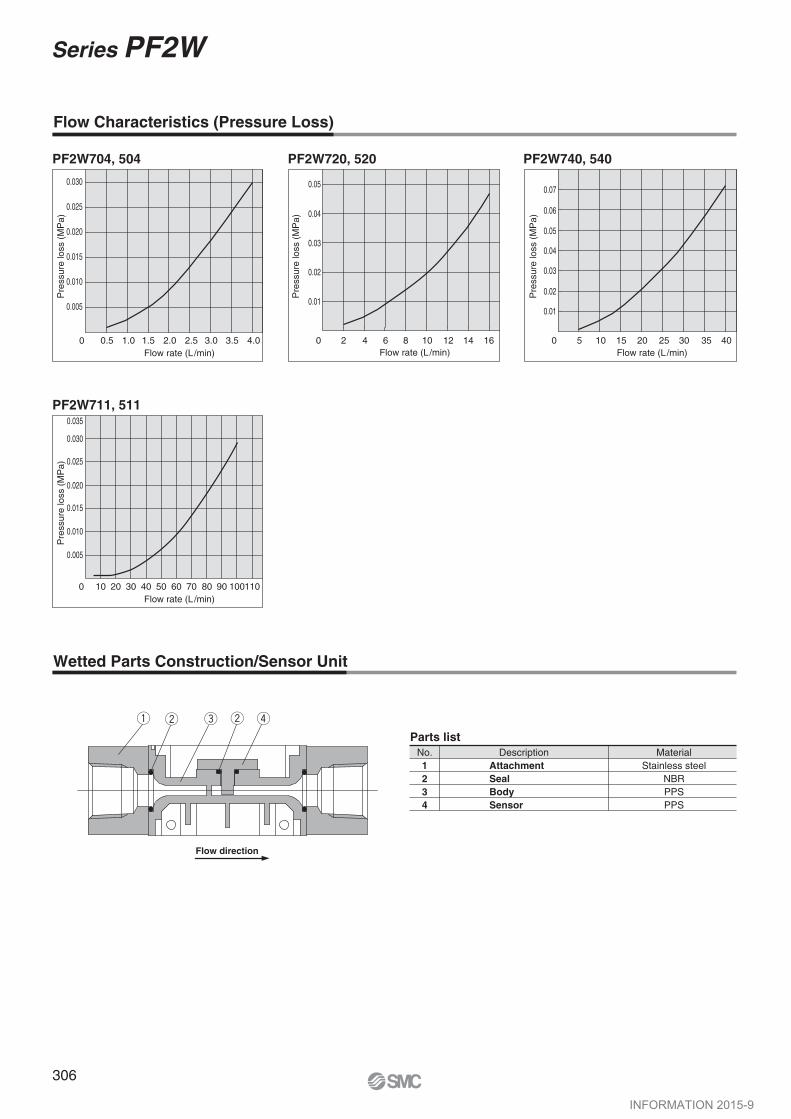
Parts listNo.1234
Description MaterialStainless steel
NBRPPSPPS
q
Flow direction
w w r
0.030
0.025
0.020
0.015
0.010
0.005
0
Pre
ssur
e lo
ss (
MP
a)
4.03.53.02.52.01.51.00.5
0.030
0.025
0.020
0.015
0.010
0.005
0 10 20 30 40 50 60 70 80 90 110100
Flow rate (L/min)
Pre
ssur
e lo
ss (
MP
a)
Flow rate (L/min)
Pre
ssur
e lo
ss (
MP
a)
Flow rate (L/min)
Pre
ssur
e lo
ss (
MP
a)
Flow rate (L/min)10 12 14 1620 4 6 8
0.02
0.03
0.04
0.05
0.010.01
0.07
0.06
0.05
0.04
0.03
0.02
4035302520151050
PF2W704, 504
PF2W711, 511
PF2W720, 520 PF2W740, 540
0.035
AttachmentSealBodySensor
e
Flow Characteristics (Pressure Loss)
Wetted Parts Construction/Sensor Unit
306
Series PF2W
INFORMATION 2015-9
12060
60
OUT1
FOR WATER
FLOW SWITCH
4 x ø4.5
50
5040
DOWN
U P
S E T
OUT2
1.61767 6
342 x Port size
34
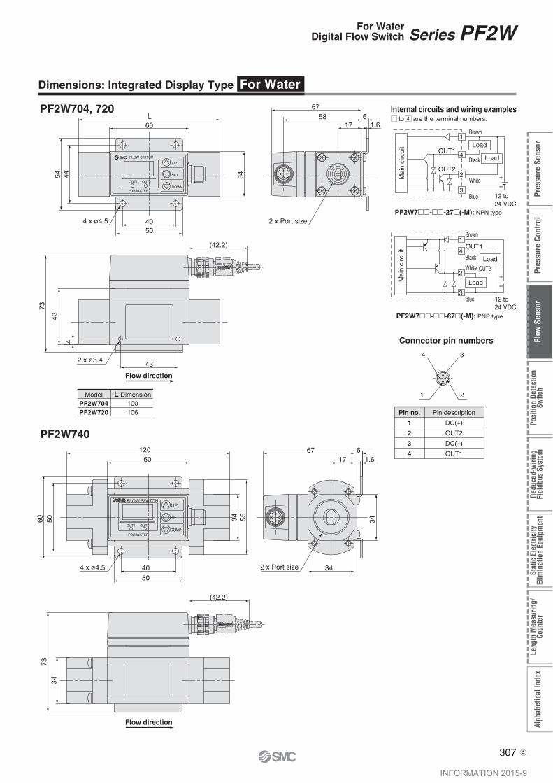
PF2W704, 720
PF2W740
DOWN
UP
SET
OUT2OUT1
FOR WATER
FLOW SWITCH
L
34
60
4454
4050
1758
67
1.6
4 3
21
Connector pin numbers
2 x Port size4 x ø4.5
6
ModelPF2W704PF2W720
L Dimension100106
PF2W7��-��-27�(-M): NPN type
PF2W7��-��-67�(-M): PNP type
34 55
OUT2
OUT1
Brown
Black
White
Blue
Load
Load
1
4
2
3
OUT11
4
2
3
Brown
Black
White
Blue
Load
LoadMai
n ci
rcui
t
Pin no.
1
2
3
4
Pin description
DC(+)
OUT2
DC(–)
OUT1
Dimensions: Integrated Display Type For Water
Internal circuits and wiring examples to are the terminal numbers.
Mai
n ci
rcui
t
+–
12 to 24 VDC
OUT2+–
12 to 24 VDC
Flow direction
Flow direction
7334
(42.2)
(42.2)
73
2 x ø3.443
42
4
307
Series PF2WFor WaterDigital Flow Switch
Alph
abet
ical
Inde
xLe
ngth
Mea
surin
g/Co
unte
rSt
atic
Ele
ctric
ityEl
imin
atio
n Eq
uipm
ent
Redu
ced-
wiri
ngFi
eldb
us S
yste
mPo
sitio
n De
tect
ion
Switc
hFl
ow S
enso
rPr
essu
re C
ontro
lPr
essu
re S
enso
r
A
INFORMATION 2015-9

9
2
PF2W711
OUT1 OUT2 DOWN
SET
U PFLOW SWITCH
4 x ø5.5
70 5888
4546
36
14880
(42.2)6046
2 x Port size
Flow direction
45
2370
79
Dimensions: Integrated Display Type For Water
308
Series PF2W
A
INFORMATION 2015-9
4
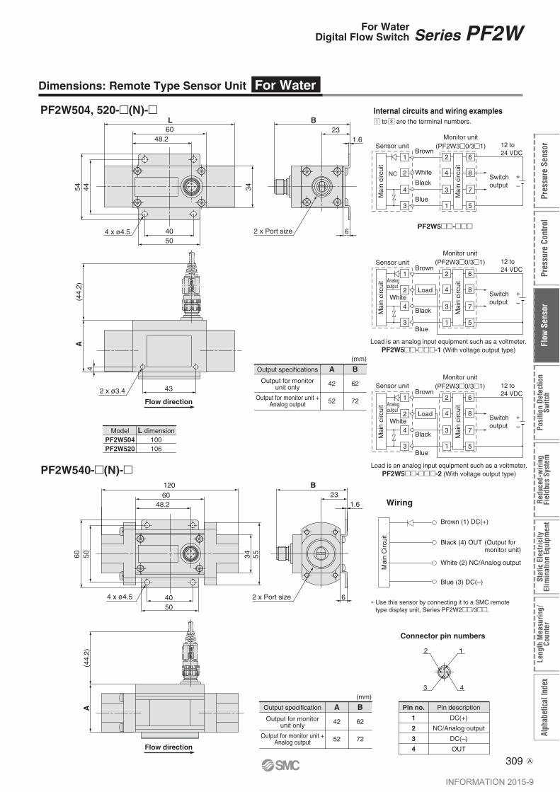
PF2W504, 520-�(N)-�
PF2W540-�(N)-�
48.260L
4454
4050
6
34
23B
1.6
2 x Port size
A
2 x ø3.4 43
(44.
2)
2 1
43
Connector pin numbers
4 x ø4.5
ModelPF2W504PF2W520
L dimension100106
5060
48.260120
4 x ø4.5
5040
1.623
34 55
B
2 x Port size
A(4
4.2)
Mai
n C
ircui
t
Brown (1) DC(+)
White (2) NC/Analog output
Blue (3) DC(–)
Output specification
Output for monitorunit only
Output for monitor unit +Analog output
B
62
72
A
42
52
Output specifications
Output for monitorunit only
Output for monitor unit +Analog output
B
62
72
A
42
52
6
Wiring
1
2
4
3
2
4
3
1
6
8
7
5
1
2
4
3
2
4
3
1
6
8
7
5
PF2W5��-���
1
2
4
3
2
4
3
1
6
8
7
5
Pin no.
1
2
3
4
Pin description
DC(+)
NC/Analog output
DC(–)
OUT
Load is an analog input equipment such as a voltmeter.PF2W5��-���-1 (With voltage output type)
Load is an analog input equipment such as a voltmeter.PF2W5��-���-2 (With voltage output type)
Dimensions: Remote Type Sensor Unit For Water
Internal circuits and wiring examples to are the terminal numbers.
Mai
n ci
rcui
t
Brown
White
Monitor unit(PF2W3�0/3�1)
BlackSwitchoutput
Blue
12 to 24 VDC
NC +–
Sensor unit
Mai
n ci
rcui
t
12 to 24 VDCBrown
White
Monitor unit(PF2W3�0/3�1)
Black
Switchoutput
Blue
+–
Mai
n ci
rcui
t
Mai
n ci
rcui
t
Sensor unit
Load
Analogoutput
12 to 24 VDCBrown
White
Monitor unit(PF2W3�0/3�1)
Black
Switchoutput
Blue
+–
Mai
n ci
rcui
t
Mai
n ci
rcui
t
Sensor unit
Load
Analogoutput
Black (4) OUT (Output for monitor unit)
∗ Use this sensor by connecting it to a SMC remote type display unit, Series PF2W2��/3��.
Flow direction
Flow direction
(mm)
(mm)
309
Series PF2WFor WaterDigital Flow Switch
Alph
abet
ical
Inde
xLe
ngth
Mea
surin
g/Co
unte
rSt
atic
Ele
ctric
ityEl
imin
atio
n Eq
uipm
ent
Redu
ced-
wiri
ngFi
eldb
us S
yste
mPo
sitio
n De
tect
ion
Switc
hFl
ow S
enso
rPr
essu
re C
ontro
lPr
essu
re S
enso
r
A
INFORMATION 2015-9
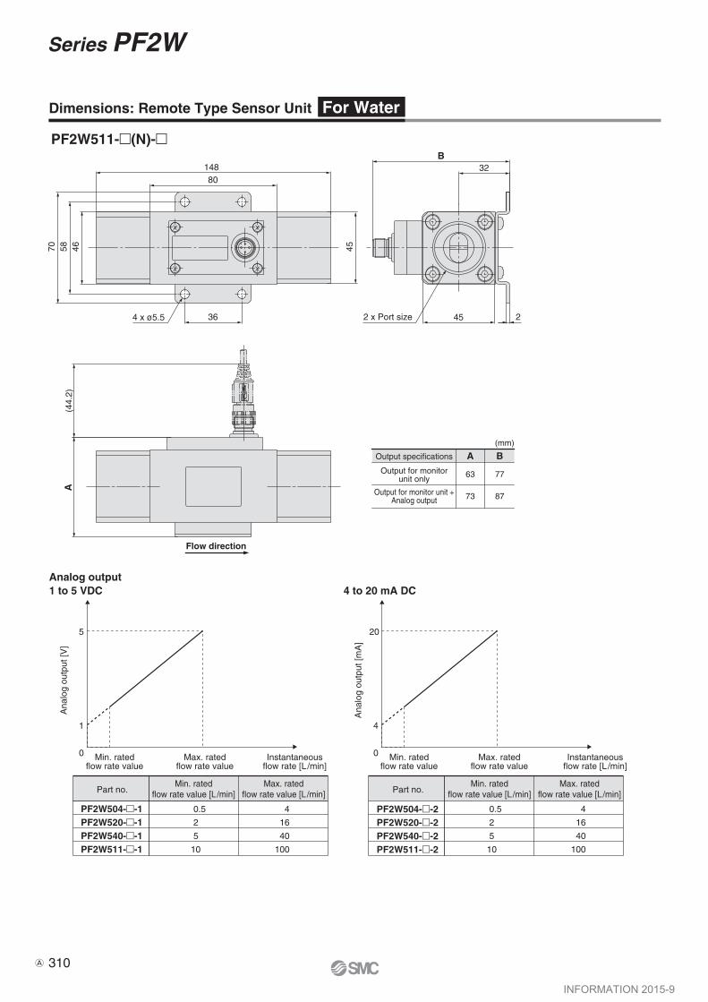
PF2W511-�(N)-�
4 x ø5.5
80148
36
46 455870
(44.
2)A
2 x Port size
32B
45 2
Output specifications
Output for monitorunit only
Output for monitor unit +Analog output
B
77
87
A
63
73
Analog output1 to 5 VDC
Min. ratedflow rate value
Max. ratedflow rate value
Instantaneousflow rate [L/min]
Min. ratedflow rate value
Max. ratedflow rate value
Instantaneousflow rate [L/min]
5
1
0
Ana
log
outp
ut [V
]
4 to 20 mA DC
20
4
0
Ana
log
outp
ut [m
A]
Dimensions: Remote Type Sensor Unit For Water
Flow direction
Part no.
PF2W504-�-1PF2W520-�-1PF2W540-�-1PF2W511-�-1
0.5
2
5
10
4
16
40
100
0.5
2
5
10
4
16
40
100
Min. ratedflow rate value [L/min]
Max. ratedflow rate value [L/min] Part no.
PF2W504-�-2PF2W520-�-2PF2W540-�-2PF2W511-�-2
Min. ratedflow rate value [L/min]
Max. ratedflow rate value [L/min]
(mm)
310
Series PF2W
A
INFORMATION 2015-9
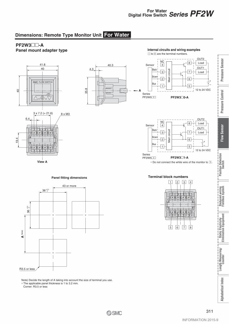
PF2W3��-APanel mount adapter type
UNIT
RESET
SET
SMC FLOW SWITCH
4041.8
40
4.340.3
35.8
1
5 6 7 8
2 3 4
A
Internal circuits and wiring examples to are the terminal numbers.
4
3
2
1
8
7
6
5
4
3
2
1
8
7
6
5
1
5 6 7 8
2 3 4
4321
8765
PF2W3�0-A
PF2W3�1-A
19.4
6.4
3 x 7.2 (= 21.6) 8 x M3
View A
Terminal block numbers
36 +0.5 0
36+
0.5
0
43 or more
A N
ote)
Panel fitting dimensions
Dimensions: Remote Type Monitor Unit For Water
R3.5 or less
Note) Decide the length of A taking into account the size of terminal you use.∗ The applicable panel thickness is 1 to 3.2 mm.
Corner: R3.5 or less
Load
Load
12 to 24 VDC
SeriesPF2W5��
Black
Brown
Blue
NCSensor
OUT2
OUT1
+–
Mai
n ci
rcui
t
SeriesPF2W5��
Load
Load
12 to 24 VDC
Black
Brown
Blue
NCSensor
OUT2
OUT1
+–
Mai
n ci
rcui
t
∗ Do not connect the white wire of the monitor to .
311
Series PF2WFor WaterDigital Flow Switch
Alph
abet
ical
Inde
xLe
ngth
Mea
surin
g/Co
unte
rSt
atic
Ele
ctric
ityEl
imin
atio
n Eq
uipm
ent
Redu
ced-
wiri
ngFi
eldb
us S
yste
mPo
sitio
n De
tect
ion
Switc
hFl
ow S
enso
rPr
essu
re C
ontro
lPr
essu
re S
enso
r
INFORMATION 2015-9

PF2W200, 201
Front protective cover + Panel mount adapter
Panel fitting dimensions
�40 6
40.1
2.5
�36
.8
CH
LL/min
SET
OUT1
FLOWSMC
46.4
53
47
�42.4
9.4 (2)
(7.5)
Dimensions: Remote Type Monitor Unit For Water (4-channel Flow Monitor)
Sensor connector
(option)
Front protective cover
Waterproof seal Panel
Panel mount adapter
∗Applicable panel thickness: 0.5 to 8 mm
55 or more
55 o
r m
ore
R1or less
�37.5+0.1-0.2
312
Series PF2W
INFORMATION 2015-9

No. of cable wire
Conductor
Insulator
Sheath
Nominal cross-sectional area
Dimension
Dimension
Material
O.D.
8
0.15 mm2
Approx. 0.5 mm
Approx. 0.9 mm Brown, White, Blue, Black, Gray, Red, Green, Yellow
Heat-resistant polyethylene
4.8 mm
Terminal
DC+
N.C.
DC–
IN: 1 to 5 V
Connector no.
1
2
3
4
Cable wire color
Brown
Not used
Blue
White
Pin No.
7 Green CH4_OUT1
8 Yellow N.C.
6 Red CH3_OUT15 Gray CH2_OUT1
4 White N.C.
3 Black CH1_OUT1
2 Blue DC(–)
1 Brown DC(+)
Power supply/Output connector (accessory)
2000
Power supply/Output connector (8P)
Pin no.
q
w
e
r
t
y
u
i
Terminal
DC (+)
DC (–)
CH1_OUT1
N.C.
CH2_OUT1
CH3_OUT1
CH4_OUT1
N.C.
iuytrewq
Sensor connector (4P x 4) Connector (option)
r
e
w
q
Pin no.
q
w
e
r
Internal circuits and wiring examplesPF2W200 PF2W201
NC
NC
NC
NC
4321
4321
4321
4321
NC
NC
NC
NC
4321
4321
4321
4321
Dimensions: Remote Type Monitor Unit For Water (4-channel Flow Monitor)
Sensor connector port
Power supply/Output connector port
Cable Specifications
DC (+)
24 VDC
+
–
(Brown)
(Black)
(Blue)
CH1_OUT1
(Gray)CH2_OUT1
(Red)CH3_OUT1
(Green)CH4_OUT1
DC (–)
Load
Load
Load
Load
Sen
sor
Sen
sor
Mai
n ci
rcui
t
Sen
sor
Sen
sor
DC (+)
24 VDC
+
–
(Brown)
(Black)
(Blue)
CH1_OUT1
(Gray)CH2_OUT1
(Red)CH3_OUT1
(Green)CH4_OUT1
DC (–) Load
Load
Load
Load
Mai
n ci
rcui
t
Sen
sor
Sen
sor
Sen
sor
Sen
sor
1CH 2 3 4
313
Series PF2WFor WaterDigital Flow Switch
Alph
abet
ical
Inde
xLe
ngth
Mea
surin
g/Co
unte
rSt
atic
Ele
ctric
ityEl
imin
atio
n Eq
uipm
ent
Redu
ced-
wiri
ngFi
eldb
us S
yste
mPo
sitio
n De
tect
ion
Switc
hFl
ow S
enso
rPr
essu
re C
ontro
lPr
essu
re S
enso
r
A
INFORMATION 2015-9

OUT1
SET
CH
L/minL
DOWN
U P
OUT2OUT1
SET
SMC FLOW SWITCH
SETRESET
UNIT
Integrated Display TypePF2A703H, 706H, 712H
4-channel Flow Monitor (Remote type/Monitor unit)PF2A200, 201PF2W200, 201
U P S E T MODE DOWN
Description
Integrated Display TypePF2A710, 750, 711, 721, 751PF2W704(T), 720(T), 740(T), 711
Remote Type/Monitor UnitPF2A300, 301, 310, 311PF2W300, 301, 330, 331
RESET button (� + � button)If the UP and DOWN buttons are pressed simultaneously, the RESET function will activate. In case of an emergency, please clear the display. The display of the accumulated flow will bereset to zero.
LED display/Red
Indicator(PF2A7��, PF2A3�� for air only)
Displays the measured flow rate, each setting condition, and error code.
Illuminates when the normal condition (nor) is selected.
Output (OUT1) display/Green
Output (OUT2) display/Red
UP button (� button)
SET button (� button)
DOWN button (� button)
Displays the output condition of OUT1. Lights up when output is turned ON.
Displays the output condition of OUT2. Lights up when output is turned ON.
Use to change the mode or to increase the set value.
Use this button to set the valve or the set mode.
Use to change the mode or decrease the set value.
RESET button (� + � button)If the UP and DOWN buttons are pressed simultaneously, the RESET function will activate. In case of an emergency, please clear the display. The display of the accumulated flow will bereset to zero.
LCD display/Orange
Output (OUT1) display/Red
Unit display/Red
Displays the measured flow rate, each setting condition, and error code.
Displays the output condition of OUT1. Lights up when output is turned ON.
Displays the selected unit. Type without unit switching function is fixed SI units (L/min, or L, m3, m3 x 103).
Flow rate confirmation display/Red
UP button (� button)
SET button (� button)
DOWN button (� button)
MODE button (� button)
The blinking intervals change depending on the flow rate value.
Use to change the mode or to increase the set value.
Use to select the function.
Use to change the mode or decrease the set value.
Use for changing the function.
Unit display of flow rate for air/Red (PF2A200, 201 for air only)
CH1 to 4 will illuminate when the normal condition (nor) is selected.
Unit display/OrangeIlluminates the selected unit. Use after putting the unit label other than L/min, L.
LCD display/Orange
Switch output display/Red
Displays the measured flow rate, each setting condition, and error code.
Displays the output condition of OUT1 (CH1 to 4). Lights up when output is turned ON.
Channel display/Red
UP button (� button)
SET button
DOWN button (� button)
Displays the selected channel.
Use to change the mode or to increase the set value.
Use this button to set the value or the set mode.
Use to change the mode or decrease the set value.
319
Series PF2A/PF2WFor Air/WaterDigital Flow Switch
Alph
abet
ical
Inde
xLe
ngth
Mea
surin
g/Co
unte
rSt
atic
Ele
ctric
ityEl
imin
atio
n Eq
uipm
ent
Redu
ced-
wiri
ngFi
eldb
us S
yste
mPo
sitio
n De
tect
ion
Switc
hFl
ow S
enso
rPr
essu
re C
ontro
lPr
essu
re S
enso
r
INFORMATION 2015-9
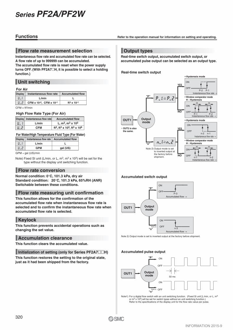
YES
NO
YES
NO
"P"
"n"
OUT1 Outputmode
• Window comparator mode H : Hysteresis
• Window comparator mode H : Hysteresis
• Hysteresis mode
• Hysteresis mode
ON
OFFP-1P-2
ON
OFFn-1n-2
ON
OFFP-1 P-2
H H
H HON
OFFn-2n-1
Instantaneous flow rate →
Instantaneous flow rate →
Instantaneous flow rate →
Instantaneous flow rate →
Note 2) Output mode is set to inverted output at the factory before shipment.
∗ OUT2 is also the same.
Flow rate conversionNormal condition: 0°C, 101.3 kPa, dry airStandard condition: 20°C, 101.3 kPa, 65%RH (ANR)Switchable between these conditions.
KeylockThis function prevents accidental operations such as changing the set value.
Accumulation clearanceThis function clears the accumulated value.
Initialization of setting (only for Series PF2A7��H)This function restores the setting to the original state,just as it had been shipped from the factory.
Flow rate measuring unit confirmationThis function allows for the confirmation of the accumulated flow rate when instantaneous flow rate is selected and to confirm the instantaneous flow rate when accumulated flow rate is selected.
Note) Fixed SI unit (L/min, or L, m3, m3 x 103) will be set for thetype without the display unit switching function.
Display Instantaneous flow rate
L/min
CFM x 10-2, CFM x 10-1
Accumulated flow
L
ft3 x 10-1
CFM = ft3/min
Display Instantaneous flow rate
L/min
GPM
Accumulated flow
L
gal (US)
For Water/High Temperature Fluid Type (For Water)
High Flow Rate Type (For Air)
GPM = gal (US)/min
Display Instantaneous flow rate
L/min
CFM
Accumulated flow
L, m3, m3 x 103
ft3, ft3 x 103, ft3 x 106
Functions Refer to the operation manual for information on setting and operating.
Flow rate measurement selectionInstantaneous flow rate and accumulated flow rate can be selected.A flow rate of up to 999999 can be accumulated.The accumulated flow rate is reset when the power supply turns OFF. (With PF2A7�H, it is possible to select a holding function.)
Unit switchingFor Air
Real-time switch output
Output typesReal-time switch output, accumulated switch output, or accumulated pulse output can be selected as an output type.
Note 2) Output mode is set to inverted output at the factory before shipment.
Accumulated switch output
"P"
"n"Note 2)
OUT1 Outputmode
ON
OFFP-3
ON
OFFn-3
Accumulated flow →
Accumulated flow →
"n"Note 2)
Note1) For a digital flow switch with an unit switching function. (Fixed SI unit [L/min, or L, m3 or m3 x 103] will be set for switch types without an unit switching function.)Refer to the specifications of the display unit for the flow rate value per pulse.
Accumulated pulse output
50 ms
ON
OFF
ON
OFF
"P"
OUT1 Outputmode
320
Series PF2A/PF2W
INFORMATION 2015-9

Error correctionLED display Contents
A current of more than 80 mA is flowing to OUT1.
A current of more than 80 mA is flowing to OUT2.
The set data has changed for some reason.
The flow rate is over the flow rate measurement range.
Check the load and the wiring for OUT1.
Check the load and thewiring for OUT2.
Perform the RESET operation, and reset all the data again.
Use an adjustment valve, etc.to reduce the flow rate until itis within the flow rate range.
Action
Note 2)
Note 2)
Note 1)
Note 1)
Note 1)
Note 1)
Note 2)
Note 1) Applicable to monitor integrated type and remote type except the PF2A7��H series.
Note 2) Applicable to the PF2A7��H series only.
LED display Contents
Over current is flowing to theload of a switch output.
Action
Internal data error.
Please contact SMC for investigation.
Turn off the power supply and then turn on it again.
Use an adjustment valve, etc. to reduce the flow rate until itis within the flow rate range.
Internal data error.
Internal data error.
Internal data error.
Internal data error.
Functions
Copy function (PF2�200, 201 only)
Information to be copied is: Flow rate rangeDisplay modeDisplay unit (Only available when the unit specification is nil.)Output methodOutput modeFlow rate display unit (available with PF2A20� only)Flow rate value
Changes displaying the channel shown every about 2 seconds and its detected flow rate.
Channel select function (PF2�200, 201 only)
Every pushing the � button, channel selection “1�2�3�4�1...” is available. The flow rate measure-ment of each selected channel is shown in the monitor unit.
The maximum or minimum value can be held in the case where the instantaneous flow rate display mode is selec-ted during the initial setting. The hold value is reset when the power supply turns OFF or the hold is released.
Peak hold, Bottom hold display function(PF2�200, 201 only)
For PF2A/W200, 201
Channel scan function (PF2�200, 201 only)
Eliminate the cause of the over current by turning off the power supply, and then turn on it again.
The flow rate is over the flow rate measurement range.
321
Series PF2A/PF2WFor Air/WaterDigital Flow Switch
Alph
abet
ical
Inde
xLe
ngth
Mea
surin
g/Co
unte
rSt
atic
Ele
ctric
ityEl
imin
atio
n Eq
uipm
ent
Redu
ced-
wiri
ngFi
eldb
us S
yste
mPo
sitio
n De
tect
ion
Switc
hFl
ow S
enso
rPr
essu
re C
ontro
lPr
essu
re S
enso
r
INFORMATION 2015-9

No. of cable wire
Conductor
Insulator
Sheath
Nominal cross-sectional area
Dimension
Dimension
Material
O.D.
4
AWG23
0.72 mm
1.14 mm Brown, White, Blue, Black
Heat-resistant and oil-resistant lead-free PVC
4.00 mm
U PDOWN
SET
OUT2
OUT1
Option
When only optional parts are required, order with the part numbers listed below.
e-con connector
ZS-28-CA-4 1
Part no. Qty.
1
Part no. Qty.
3 m
Lead wire length
Option
When only optional parts are required, order with the part numbers listed below.
Lead wire with M12 connector
PF2A7�� (H)PF2W7�� (T)
PF2A5��PF2W5�� (T)
e-con connector
PF2A20�PF2W20�
ZS-28-CA-4 1
Part no. Qty.
ZS-37-APart no. Qty. Lead wire length
Lead wire with M12 connector
Lead wire with M12 connector
e-con connector
Cable Specifications
In addition to the connectors shown above, those listed below (e-con) can beconnected.
Sumitomo 3M Limited
Tyco Electronics Japan G.K.
OMRON Corp.
37104-3122-000FL
2-1473562-4
XN2A-1430
Manufacturer Model
Correns Corp.
OMRON Corp.
Yamatake Corp.
HIROSE ELECTRIC CO., LTD.
DDK Ltd.
VA-4D
XS2
PA5-4I
HR24
CM01-8DP4S
Manufacturer Applicable series
4
Pin no.
M12
Connector size
In addition to the lead wire assembly shown above, those listed below (female contact) can be connected.However, they cannot be connected with an e-con connector because the diameter of the core wire and its coverage diameter are different. For details, contact each manufacturer.Contact each manufacturer for details including RoHS compliance.
Panel mounting
Panel mount adapter A, BZS-22-EDescription
With mounting bracket
NotePin no.
Panel mount adapter
Front protective cover + Panel mount adapter
ZS-26-BZS-26-C
Description
With waterproof seal, mounting screw
With waterproof seal, mounting screw
NotePart no.
PF2A3��PF2W3��
Panel mount adapter A
Panel
Panel mount adapter BMounting bracket
(accessory)PF2A20��PF2W20��
Waterproof seal(accessory)
Front protective cover
Panel
Panel mount adapter
Mounting screw (M3 x 8 L)
(accessory)
322
Series PF2A/PF2W
INFORMATION 2015-9