1MRK506180-BEN a en Protect IT Line Differential and Distance Protection Terminal REL 561 2.5
94
Page 1 1MRK 506 180-BEN Revision: A Issued: October 2003 Data subject to change without notice • Open termi nal with extens ive config uratio n possibilities and expandable hardware design to meet specific user requirements • Phase-segregated line differential protec- tion with charging current compensation • Full scheme phas e-t o-phas e and pha se- to- earth distance protection • Wide range of phase and residual overcur- rent protection functions • The rmal overload protection • Ve rsati le local human -machi ne inter face (LED-HMI) • Ext ensive sel f-s upervision wi th inte rnal event recorder • Ti me synchronization with 1 ms reso luti on • Four indepen dent grou ps of complete set- ting parameters • Powerf ul software PC ‘tool-box’ for moni- toring, evalution and user configuration • Line distance - Di st ance pr otecti on (Z M) - Simpli fie d impedance sett ings (SI S) - Additi ons f or series compensated ne t- works (SCN) - Phase sel ecti on lo gic (PHS) - Pow er swing detection (PSD) - Pow er swing addi tional logic (PSL) - Scheme commun icat ion l ogic (ZC OM) - Cur rent rev ers al an d wea k end i nfeed logic (ZCAL) - Rad ial f eed er pr ote cti on (P AP) - Aut omatic s wit ch onto fau lt log ic (SOTF) - Loc al a cceleration log ic ( ZCL C) • Line dif ferential - Line diff ere nti al protec tion, phase segr e- gated (DIFL) - Chargi ng cur rent compensat ion (CCC) • Current - Instan taneous non-direc tional phase overcurrent protection (IOCph) - Instan taneous non-directional residual overcurrent protection (IOCr) - Definite time non- direct ion al pha se overcurrent protection (TOCph) - Definite time non-direct ion al residual overcurrent protection (TOCr) - T wo ste p time delayed non-directional phase overcurrent protection (TOC2) - T wo ste p time dela yed di rectional phase overcurrent protection (TOC3) - Time delayed non- directional residual overcurrent protection (TEF) - Ti me del ayed dire cti onal resi dual over - current protection (TEFdir) - Fou r step time delayed directi onal res id- ual overcurrent protection (EF4) - Sen sit ive di rect ional res idual overcur- rent protection (WEF1) - Sensitive directional residual power pro- tection (WEF2) - Scheme communication l ogi c for r esi d- ual overcurrent protection (EFC) - Current rever sal and weak en d inf eed logic for residual overcurrent protection (EFCA) - Thermal overload protection (T HOL ) - Stub pr otecti on ( STUB) - Br eak er f ailu re p rotect ion (BF P)
-
Upload
nguoi-trong-giang-ho -
Category
Documents
-
view
216 -
download
0
Transcript of 1MRK506180-BEN a en Protect IT Line Differential and Distance Protection Terminal REL 561 2.5
8/11/2019 1MRK506180-BEN a en Protect IT Line Differential and Distance Protection Terminal REL 561 2.5
http://slidepdf.com/reader/full/1mrk506180-ben-a-en-protect-it-line-differential-and-distance-protection-terminal 1/94
Page 1
1MRK 506 180-BEN
Revision: A
Issued: October 2003Data subject to change without notice
• Open terminal with extensive configurationpossibilities and expandable hardwaredesign to meet specific user requirements
• Phase-segregated line differential protec-tion with charging current compensation
• Full scheme phase-to-phase and phase-to-earth distance protection
• Wide range of phase and residual overcur-rent protection functions
• Thermal overload protection
• Versatile local human-machine interface(LED-HMI)
• Extensive self-supervision with internal
event recorder• Time synchronization with 1 ms resolution
• Four independent groups of complete set-ting parameters
• Powerful software PC ‘tool-box’ for moni-toring, evalution and user configuration
• Line distance
- Distance protection (ZM)
- Simplified impedance settings (SIS)
- Additions for series compensated net-works (SCN)
- Phase selection logic (PHS)
- Power swing detection (PSD)
- Power swing additional logic (PSL)
- Scheme communication logic (ZCOM)
- Current reversal and weak end infeedlogic (ZCAL)
- Radial feeder protection (PAP)
- Automatic switch onto fault logic (SOTF)
- Local acceleration logic (ZCLC)
• Line differential
- Line differential protection, phase segre-gated (DIFL)
- Charging current compensation (CCC)
• Current
- Instantaneous non-directional phaseovercurrent protection (IOCph)
- Instantaneous non-directional residualovercurrent protection (IOCr)
- Definite time non-directional phaseovercurrent protection (TOCph)
- Definite time non-directional residual
overcurrent protection (TOCr)- Two step time delayed non-directional
phase overcurrent protection (TOC2)
- Two step time delayed directional phaseovercurrent protection (TOC3)
- Time delayed non-directional residualovercurrent protection (TEF)
- Time delayed directional residual over-current protection (TEFdir)
- Four step time delayed directional resid-ual overcurrent protection (EF4)
- Sensitive directional residual overcur-rent protection (WEF1)
- Sensitive directional residual power pro-tection (WEF2)
- Scheme communication logic for resid-ual overcurrent protection (EFC)
- Current reversal and weak end infeedlogic for residual overcurrent protection(EFCA)
- Thermal overload protection (THOL)
- Stub protection (STUB)
- Breaker failure protection (BFP)

8/11/2019 1MRK506180-BEN a en Protect IT Line Differential and Distance Protection Terminal REL 561 2.5
http://slidepdf.com/reader/full/1mrk506180-ben-a-en-protect-it-line-differential-and-distance-protection-terminal 2/94
8/11/2019 1MRK506180-BEN a en Protect IT Line Differential and Distance Protection Terminal REL 561 2.5
http://slidepdf.com/reader/full/1mrk506180-ben-a-en-protect-it-line-differential-and-distance-protection-terminal 3/94

8/11/2019 1MRK506180-BEN a en Protect IT Line Differential and Distance Protection Terminal REL 561 2.5
http://slidepdf.com/reader/full/1mrk506180-ben-a-en-protect-it-line-differential-and-distance-protection-terminal 4/94
1MRK 506 180-BEN
Page 4
Common functions are the software functionsalways included in the terminals.
Use the local HMI, SMS or SCS to view thestatus of the self-supervision function. Theself-supervision operates continuously andincludes:
• Normal micro-processor watchdog func-tion
• Checking of digitized measuring signals• Checksum verification of PROM contents
and all types of signal communication
Use the time synchronization source selectorto select a common source of absolute timefor the terminal when it is a part of a protec-tion system. This makes comparison ofevents and disturbance data between all ter-
minals in a SA system possible.
Two main alternatives of external time syn-chronization are available. Either the syn-chronization message is applied via any ofthe communication ports of the terminal as atelegram message including date and time, oras a minute pulse, connected to a binaryinput. The minute pulse is used to fine tunealready existing time in the terminals.
The REx 5xx terminal has its own internalclock with date, hour, minute, second and
millisecond. It has a resolution of 1 ms.
The clock has a built-in calendar that handlesleap years through 2098. Any changebetween summer and winter time must behandled manually or through external timesynchronization. The clock is powered by acapacitor, to bridge interruptions in powersupply without malfunction.
The internal clock is used for time-taggingdisturbances, events in Substation monitoringsystem (SMS) and Substation control system(SCS), and internal events.
Use the four sets of settings to optimize theterminals operation for different system con-ditions. By creating and switching betweenfine tuned setting sets, either from the human-machine interface or configurable binaryinputs, results in a highly adaptable terminalthat can cope with a variety of system scenar-ios.
The GRP function block has four functionalinputs, each corresponding to one of the set-ting groups stored within the terminal. Acti-vation of any of these inputs changes theactive setting group. Four functional outputsignals are available for configuration pur-poses, so that continuous information onactive setting group is available.
The user can with the available logic functionblocks build logic functions and configure theterminal to meet application specific require-ments.
Different protection, control, and monitoringfunctions within the REx 5xx terminals arequite independent as far as their configurationin the terminal is concerned. The user can notchange the basic algorithms for differentfunctions. But these functions combined withthe logic function blocks can be used to cre-ate application specific functionality.
The inverter function block INV has one
input and one output, where the output is ininverse ratio to the input.
The OR function is used to form generalcombinatory expressions with boolean vari-ables. The OR function block has six inputsand two outputs. One of the outputs isinverted.
The AND function is used to form generalcombinatory expressions with boolean vari-ables.The AND function block has fourinputs and two outputs. One of the inputs andone of the outputs are inverted.
8/11/2019 1MRK506180-BEN a en Protect IT Line Differential and Distance Protection Terminal REL 561 2.5
http://slidepdf.com/reader/full/1mrk506180-ben-a-en-protect-it-line-differential-and-distance-protection-terminal 5/94
1MRK 506 180-BEN
Page 5
The function block TM timer has drop-outand pick-up delayed outputs related to theinput signal. The timer has a settable timedelay (parameter T).
The function block TL timer with extendedmaximum time delay at pick-up and at drop-out, is identical with the TM timer. The dif-ference is the longer time delay.
The pulse function can be used, for example,for pulse extensions or limiting of operationof outputs. The pulse timer TP has a settablelength.
The function block TQ pulse timer withextended maximum pulse length, is identicalwith the TP pulse timer. The difference is thelonger pulse length.
The exclusive OR function XOR is used togenerate combinatory expressions with bool-ean variables. The function block XOR hastwo inputs and two outputs. One of the out-puts is inverted. The output signal is 1 if theinput signals are different and 0 if they areequal.
The Set-Reset (SR) function is a flip-flop thatcan set or reset an output from two inputsrespectively. Each SR function block has twooutputs, where one is inverted.
The Set-Reset function SM is a flip-flop withmemory that can set or reset an output fromtwo inputs respectively. Each SM functionblock has two outputs, where one is inverted.The memory setting controls if the flip-flopafter a power interruption will return the stateit had before or if it will be reset.
The GT function block is used for controllingif a signal should be able to pass from theinput to the output or not depending on a set-ting.
The function block TS timer has outputs fordelayed input signal at drop-out and at pick-up. The timer has a settable time delay. It also
has an Operation setting On, Off that controlsthe operation of the timer.
The Move function block MOF is put first inthe slow logic and is used for signals comingfrom fast logic into the slow logic. The MOFfunction block is only a temporary storage forthe signals and does not change any valuebetween input and output.
The Move function block MOL is put last inthe slow logic and is used for signals goingout from the slow logic to the fast logic. TheMOL function block is only a temporary stor-age for the signals and does not change anyvalue between input and output.
When using a Substation Automation system,events can be spontaneously sent or polledfrom the terminal to the station level. Theseevents are created from any available signalin the terminal that is connected to the eventfunction block. The event function block canalso handle double indication, that is nor-mally used to indicate positions of high-volt-age apparatuses. With this event functionblock, data also can be sent to other terminalsover the interbay bus.
As basic, 12 event function blocks EV01-EV12 running with a fast cyclicity, are avail-able in REx 5xx. When the function Appara-tus control is used in the terminal, additional32 event function blocks EV13-EV44, run-ning with a slower cyclicity, are available.
Each event function block has 16 connecta-bles corresponding to 16 inputs INPUT1 toINPUT16. Every input can be given a namewith up to 19 characters from the CAP 540configuration tool.
The inputs can be used as individual events orcan be defined as double indication events.
The inputs can be set individually, from theParameter Setting Tool (PST) under theMask-Event function, to create an event atpick-up, drop-out or at both pick-up anddrop-out of the signal.
The event function blocks EV01-EV06 haveinputs for information numbers and functiontype, which are used to define the events
according to the communication standard IEC60870-5-103.
8/11/2019 1MRK506180-BEN a en Protect IT Line Differential and Distance Protection Terminal REL 561 2.5
http://slidepdf.com/reader/full/1mrk506180-ben-a-en-protect-it-line-differential-and-distance-protection-terminal 6/94
1MRK 506 180-BEN
Page 6
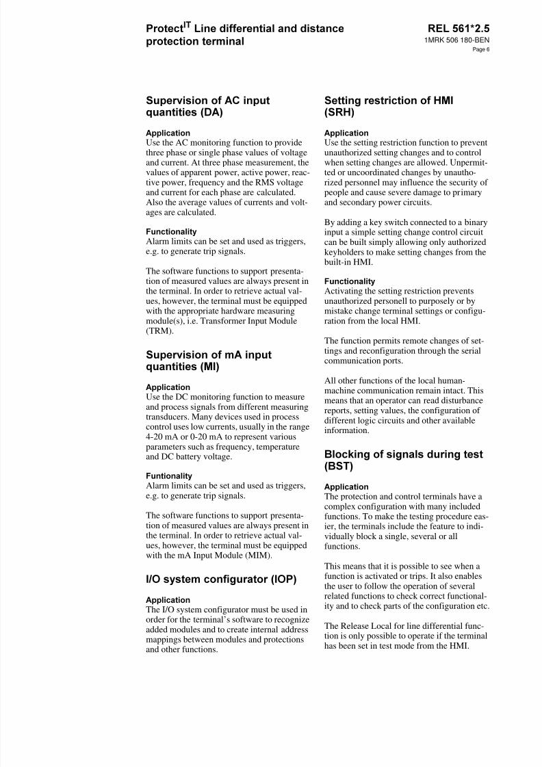
Use the AC monitoring function to providethree phase or single phase values of voltageand current. At three phase measurement, thevalues of apparent power, active power, reac-tive power, frequency and the RMS voltageand current for each phase are calculated.Also the average values of currents and volt-ages are calculated.
Alarm limits can be set and used as triggers,e.g. to generate trip signals.
The software functions to support presenta-tion of measured values are always present inthe terminal. In order to retrieve actual val-ues, however, the terminal must be equippedwith the appropriate hardware measuringmodule(s), i.e. Transformer Input Module(TRM).
Use the DC monitoring function to measureand process signals from different measuringtransducers. Many devices used in processcontrol uses low currents, usually in the range4-20 mA or 0-20 mA to represent variousparameters such as frequency, temperatureand DC battery voltage.
Alarm limits can be set and used as triggers,e.g. to generate trip signals.
The software functions to support presenta-tion of measured values are always present in
the terminal. In order to retrieve actual val-ues, however, the terminal must be equippedwith the mA Input Module (MIM).
The I/O system configurator must be used inorder for the terminal’s software to recognizeadded modules and to create internal addressmappings between modules and protectionsand other functions.
Use the setting restriction function to preventunauthorized setting changes and to controlwhen setting changes are allowed. Unpermit-ted or uncoordinated changes by unautho-rized personnel may influence the security ofpeople and cause severe damage to primaryand secondary power circuits.
By adding a key switch connected to a binaryinput a simple setting change control circuitcan be built simply allowing only authorizedkeyholders to make setting changes from thebuilt-in HMI.
Activating the setting restriction preventsunauthorized personell to purposely or bymistake change terminal settings or configu-ration from the local HMI.
The function permits remote changes of set-tings and reconfiguration through the serialcommunication ports.
All other functions of the local human-machine communication remain intact. This
means that an operator can read disturbancereports, setting values, the configuration ofdifferent logic circuits and other availableinformation.
The protection and control terminals have acomplex configuration with many includedfunctions. To make the testing procedure eas-ier, the terminals include the feature to indi-
vidually block a single, several or allfunctions.
This means that it is possible to see when afunction is activated or trips. It also enablesthe user to follow the operation of severalrelated functions to check correct functional-ity and to check parts of the configuration etc.
The Release Local for line differential func-tion is only possible to operate if the terminalhas been set in test mode from the HMI.

8/11/2019 1MRK506180-BEN a en Protect IT Line Differential and Distance Protection Terminal REL 561 2.5
http://slidepdf.com/reader/full/1mrk506180-ben-a-en-protect-it-line-differential-and-distance-protection-terminal 7/94
1MRK 506 180-BEN
Page 7
The ZM distance protection function providesfast and reliable protection for overhead linesand power cables in all kinds of power net-works. For each independent distance protec-tion zone, full scheme design providescontinuous measurement of impedance sepa-rately in three independent phase-to-phasemeasuring loops as well as in three indepen-dent phase-to-earth measuring loops.
Phase-to-phase distance protection is suitableas a basic protection function against two-and three-phase faults in all kinds of net-works, regardless of the treatment of the neu-tral point. Independent setting of the reach in
the reactive and the resistive direction foreach zone separately, makes it possible to cre-ate fast and selective short circuit protection
in power systems.
Phase-to-earth distance protection serves asbasic earth fault protection in networks withdirectly or low impedance earthed networks.Together with an independent phase prefer-ence logic, it also serves as selective protec-tion function at cross-country faults inisolated or resonantly earthed networks.
Independent reactive reach setting for phase-to-phase and for phase-to-earth measurementsecures high selectivity in networks with dif-ferent protective relays used for short-circuitand earth-fault protection.
Figure 1: Schematic presentation of the operating characteristic for one distance protection zone in forwarddirection
Distance protection with simplified settingparameters is available on request. It uses thesame algorithm as the basic distance protec-tion function. Simplified setting parametersreduce the complexity of necessary setting
procedures and make the operating character-istic automatically more adjusted to the needsin combined networks with off-lines andcables.
Where:
Xph-e = reactive reach for ph-e faults
Xph-ph = reactive reach for ph-ph faults
Rph-e = resistive reach for ph-e faults
Rph-ph = resistive reach for ph-ph faultsZline = line impedance
R
jX
Rph-eRph-ph
Xph-e
Xph-ph
Zline
98000062.vmf
8/11/2019 1MRK506180-BEN a en Protect IT Line Differential and Distance Protection Terminal REL 561 2.5
http://slidepdf.com/reader/full/1mrk506180-ben-a-en-protect-it-line-differential-and-distance-protection-terminal 8/94
1MRK 506 180-BEN
Page 8
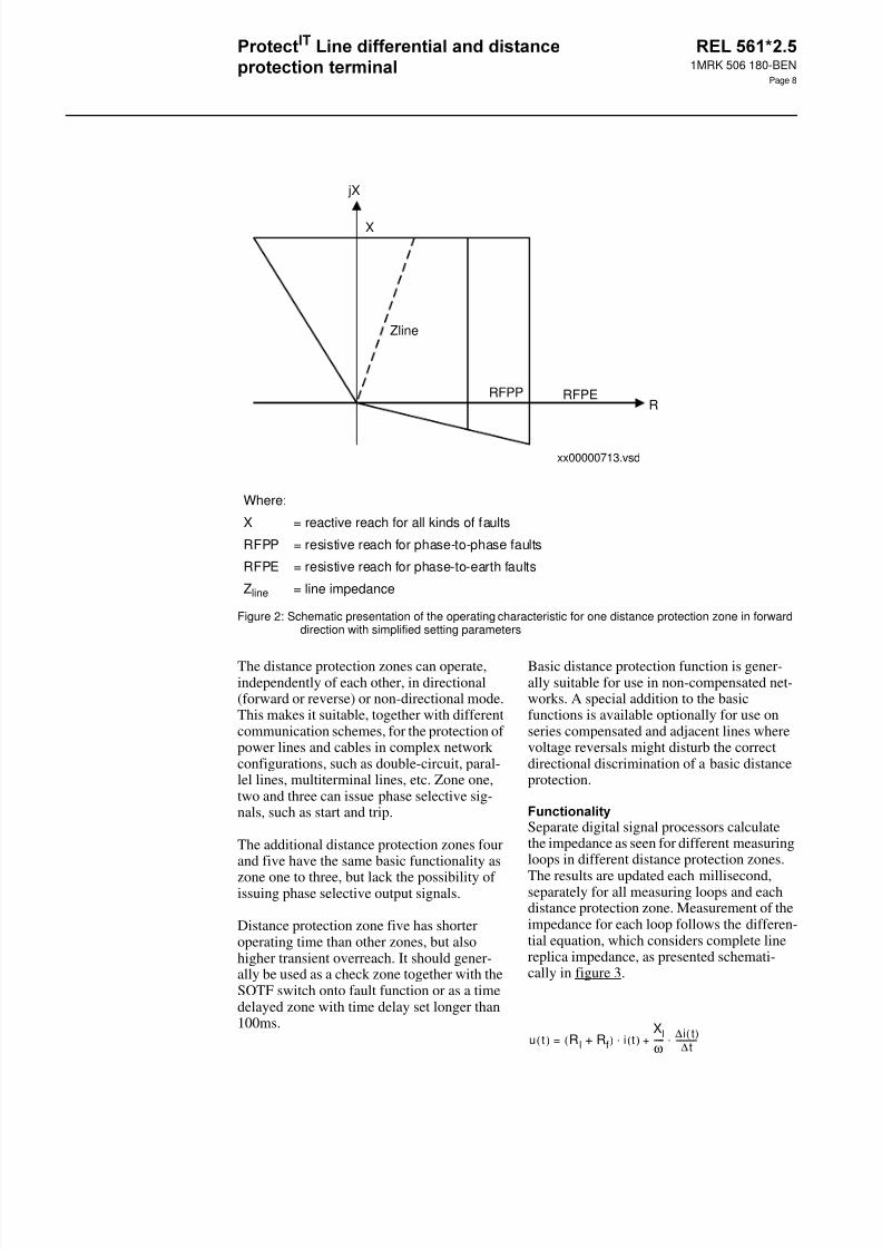
Figure 2: Schematic presentation of the operating characteristic for one distance protection zone in forwarddirection with simplified setting parameters
The distance protection zones can operate,independently of each other, in directional(forward or reverse) or non-directional mode.This makes it suitable, together with differentcommunication schemes, for the protection ofpower lines and cables in complex networkconfigurations, such as double-circuit, paral-lel lines, multiterminal lines, etc. Zone one,two and three can issue phase selective sig-nals, such as start and trip.
The additional distance protection zones fourand five have the same basic functionality aszone one to three, but lack the possibility ofissuing phase selective output signals.
Distance protection zone five has shorteroperating time than other zones, but alsohigher transient overreach. It should gener-ally be used as a check zone together with theSOTF switch onto fault function or as a timedelayed zone with time delay set longer than100ms.
Basic distance protection function is gener-ally suitable for use in non-compensated net-works. A special addition to the basicfunctions is available optionally for use onseries compensated and adjacent lines wherevoltage reversals might disturb the correctdirectional discrimination of a basic distanceprotection.
Separate digital signal processors calculatethe impedance as seen for different measuringloops in different distance protection zones.
The results are updated each millisecond,separately for all measuring loops and eachdistance protection zone. Measurement of theimpedance for each loop follows the differen-tial equation, which considers complete linereplica impedance, as presented schemati-cally in figure 3.
Where:
X = reactive reach for all kinds of faults
RFPP = resistive reach for phase-to-phase faults
RFPE = resistive reach for phase-to-earth faults
Zline = line impedance
R
xx00000713.vsd
jX
RFPERFPP
X
Zline
u t( ) R l Rf+( ) i t( )Xlω-----
∆i t( )∆t------------⋅+⋅=

8/11/2019 1MRK506180-BEN a en Protect IT Line Differential and Distance Protection Terminal REL 561 2.5
http://slidepdf.com/reader/full/1mrk506180-ben-a-en-protect-it-line-differential-and-distance-protection-terminal 9/94
1MRK 506 180-BEN
Page 9
Figure 3: Schematic presentation of impedancemeasuring principle.
Settings of all line parameters, such as posi-tive sequence resistance and reactance as wellas zero-sequence resistance and reactance,together with expected fault resistance for
phase-to-phase and phase-to-earth faults, areindependent for each zone. The operatingcharacteristic is thus automatically adjustedto the line characteristic angle, if the simpli-fied operating characteristic has not beenespecially requested. The earth-return com-pensation factor for the earth-fault measure-ment is calculated automatically by theterminal itself.
Voltage polarization for directional measure-ment uses continuous calculation and updat-ing of the positive sequence voltage for eachmeasuring loop separately. This secures cor-rect directionality of the protection at differ-ent evolving faults within the complexnetwork configurations. A memory retainingthe pre-fault positive-sequence voltagesecures reliable directional operation at close-up three-phase faults.
The distance protection function blocks areindependent of each other for each zone.Each function block comprises a number ofdifferent functional inputs and outputs, whichare freely configurable to different externalfunctions, logic gates, timers and binary
inputs and outputs. This makes it possible toinfluence the operation of the complete mea-
suring zone or only its tripping function bythe operation of fuse-failure function, powerswing detection function, etc.
The PHS phase selection logic function is anindependent measuring function. It comprisesboth impedance and current-based measure-ment criteria. Its main purpose is to augmentthe phase selectivity of the complete distanceprotection in networks with long and heavilyloaded lines. It is generally intended for usein directly earthed networks, where correctand reliable phase selection for single-phase-to-earth faults, combined with single-poletripping and automatic reclosing, secures the
stability of complete power systems.The independent measurement of impedancein all six fault loops secures a high degree ofphase selectivity in complex networks. Thisindependent phase selection, combined withdirectional measurement for each fault loop,also secures selective operation for simulta-neous close-in faults on parallel circuits.Independent reactive reach settings for phase-to-phase and phase-to-earth measurementsecures high selectivity in networks with dif-ferent protective relays used for short-circuitand earth-fault protection.
For the impedance-based phase selection, allsix fault loops are measured separately andcontinuously. The reactive and resistivereaches are independently settable for phase-to-phase and phase-to-earth faults. Checksbased on the level of residual current deter-mine which loops, i.e. phase-to-earth orphase-to-phase, are evaluated. Selection ofthe faulted phase(s) is determined by whichof the selected loops operate. Operation of aloop occurs when the measured impedancewithin that loop is within the set boundariesof the characteristic. The impedance-basedoutput will activate the selected loop of thedistance protection measuring zone(s) towhich the impedance-based phase selectionoutput is connected.
The current-based phase selection is based onthe same residual current checks as thoseused to select the phase-to-earth or phase-to-phase loops of the impedance-based phaseselection function for evaluation. In this casethe current-based output will activate eitherall the phase-to-earth loops or all the phase-
to-phase loops of the distance protection mea-
Where:
Rl = line resistance
Rf = fault resistance
Xl = line reactance
ω = 2πf
f = frequency
Rl jXl
Rfu(t)
i(t)
98000063.vmf
8/11/2019 1MRK506180-BEN a en Protect IT Line Differential and Distance Protection Terminal REL 561 2.5
http://slidepdf.com/reader/full/1mrk506180-ben-a-en-protect-it-line-differential-and-distance-protection-terminal 10/94
1MRK 506 180-BEN
Page 10
suring zone(s) to which the current-basedphase selection output is configured.
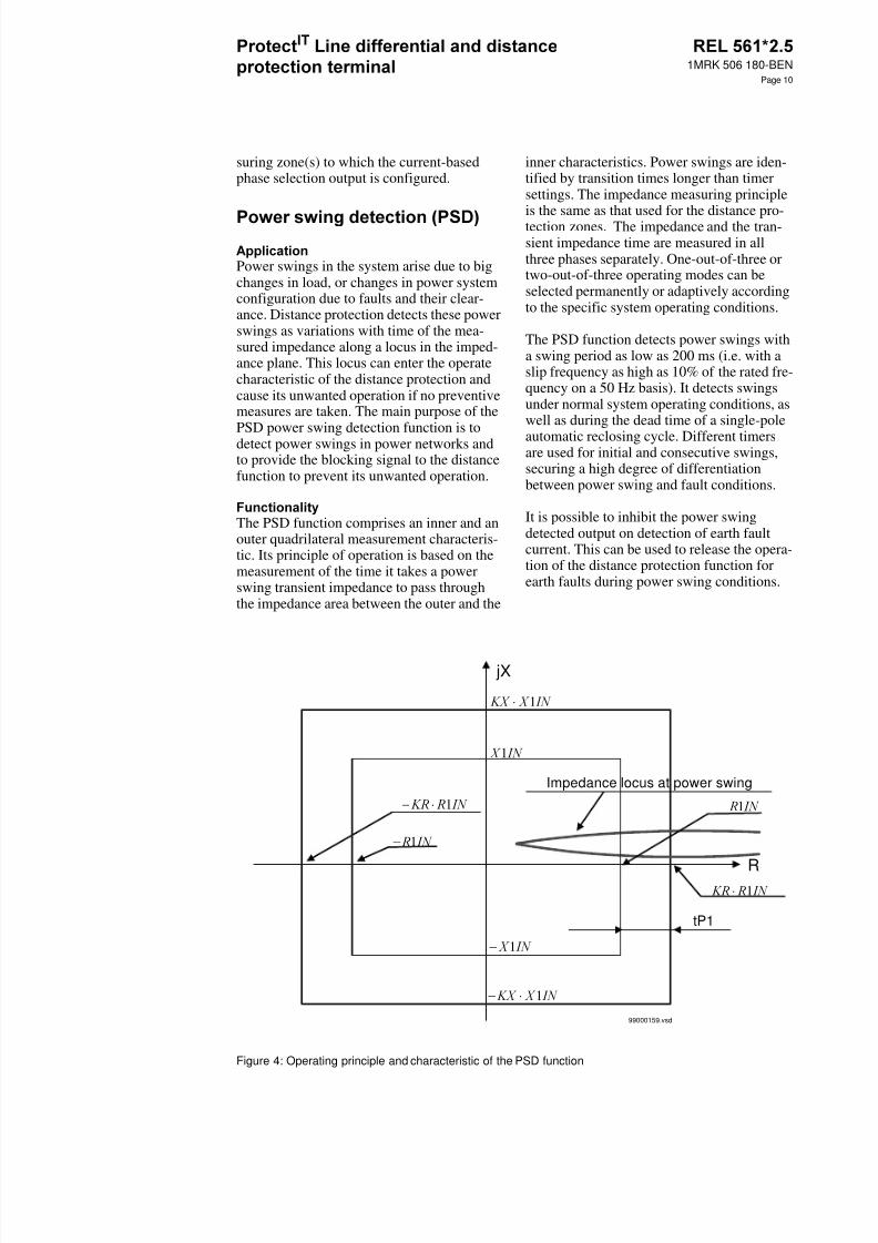
Power swings in the system arise due to bigchanges in load, or changes in power systemconfiguration due to faults and their clear-ance. Distance protection detects these powerswings as variations with time of the mea-sured impedance along a locus in the imped-ance plane. This locus can enter the operatecharacteristic of the distance protection andcause its unwanted operation if no preventivemeasures are taken. The main purpose of thePSD power swing detection function is todetect power swings in power networks andto provide the blocking signal to the distancefunction to prevent its unwanted operation.
The PSD function comprises an inner and anouter quadrilateral measurement characteris-tic. Its principle of operation is based on themeasurement of the time it takes a powerswing transient impedance to pass throughthe impedance area between the outer and the
inner characteristics. Power swings are iden-tified by transition times longer than timersettings. The impedance measuring principle
is the same as that used for the distance pro-tection zones. The impedance and the tran-sient impedance time are measured in allthree phases separately. One-out-of-three ortwo-out-of-three operating modes can beselected permanently or adaptively accordingto the specific system operating conditions.
The PSD function detects power swings witha swing period as low as 200 ms (i.e. with aslip frequency as high as 10% of the rated fre-quency on a 50 Hz basis). It detects swingsunder normal system operating conditions, aswell as during the dead time of a single-poleautomatic reclosing cycle. Different timersare used for initial and consecutive swings,securing a high degree of differentiationbetween power swing and fault conditions.
It is possible to inhibit the power swingdetected output on detection of earth faultcurrent. This can be used to release the opera-tion of the distance protection function forearth faults during power swing conditions.
Figure 4: Operating principle and characteristic of the PSD function
jX
R
tP1
Impedance locus at power swing
99000159.vsd
− ⋅ 1
− 1
1
⋅ 1
− ⋅ 1
⋅ 1
− 1
1
8/11/2019 1MRK506180-BEN a en Protect IT Line Differential and Distance Protection Terminal REL 561 2.5
http://slidepdf.com/reader/full/1mrk506180-ben-a-en-protect-it-line-differential-and-distance-protection-terminal 11/94
1MRK 506 180-BEN
Page 11
The main purpose of the PSL power swinglogic is to secure selective and reliable opera-tion of the distance protection for both inter-nal and external faults during power swings.It also ensures stable operation of the distanceprotection for power swings caused by theclearance of external faults, i.e. power swingsthat begin from within the characteristic of anoverreaching zone, and which are thereforenot able to be detected by the power swingdetection function in the normal way.
The PSL is a supplementary function to thepower swing detection function. It requiresfor its operation inputs from the distance pro-tection function, the power swing detectionfunction, etc., and the teleprotection equip-ment, when available.
Reliable operation for faults during powerswings is achieved by the communicationlogic within the PSL. For its operation, thisfunction requires inputs from a distance pro-tection zone(s) that are not used for the ordi-nary distance protection, and therefore that
are not blocked by the power swing detectionfunction on detection of a power swing. Forthis reason it is recommended to include zone4 and/or zone 5 within the terminal.
The PSL is only activated following detectionof a power swing by the power swing detec-tion function.It can operate in both permis-sive overreaching (one power swing zonerequired) and permissive underreaching (twopower swing zones required) modes. It is pos-sible to use the same communication chan-nels as for the normal scheme communicationbecause the normal distance zones which uti-lize these channels are blocked during powerswings.
For single-line-to-earth faults, an alternativeearth fault protection function, e.g. direc-tional earth fault, may be preferred to dealwith earth faults during a power swing. It isthen possible to block the power swing logicon pickup of this protection, except duringthe pole open period of a single-pole auto-matic reclosing cycle.
For power swings caused by external faultsmeasured within the power swing characteris-tic, stable operation is ensured in these cir-
cumstances by automatically replacing theoutput connections from the normal instanta-neous direct tripping distance zone with out-put connections from the PSL.
It is not possible to set a underreaching dis-tance protection zone to cover the full lengthof the line, and at the same time not to over-reach for faults beyond the protected line. To
avoid overreaching, underreaching distanceprotection zones must always reach short ofthe remote end of the line by some safetymargin of 15-20%. The main purpose of theZCOM scheme communication logic is tosupplement the distance protection functionsuch that fast clearance of faults is alsoachieved at the line end for which the faultsare on the part of the line not covered by itsunderreaching zone. To accomplish this, onecommunication channel, capable of transmit-ting an on/off signal, is required in eachdirection.
The ZCOM function is a logical functionbuilt-up from logical elements. It is a supple-mentary function to the distance protection,requiring for its operation inputs from the dis-tance protection and the teleprotection equip-ment.
The type of communication-aided scheme tobe used can be selected by way of the set-tings. The ability to select which distanceprotection zone is assigned to which input ofthe ZCOM logic makes this logic able to sup-
port practically any scheme communicationrequirements regardless of their basic operat-ing principle. The outputs to initiate trippingand sending of the teleprotection signal aregiven in accordance with the type of commu-nication-aided scheme selected and the dis-tance protection zone(s) which have operated.
When power line carrier communicationchannels are used, unblocking logic is pro-vided which uses the loss of guard signal.This logic compensates for the lack ofdependability due to the transmission of thecommand signal over the faulted line.
8/11/2019 1MRK506180-BEN a en Protect IT Line Differential and Distance Protection Terminal REL 561 2.5
http://slidepdf.com/reader/full/1mrk506180-ben-a-en-protect-it-line-differential-and-distance-protection-terminal 12/94
1MRK 506 180-BEN
Page 12
In interconnected systems, for parallel lineapplications, the direction of flow of the faultcurrent on the healthy line can change whenthe circuit breakers on the faulty line open toclear the fault. This can lead to unwantedoperation of the distance protection on thehealthy line when permissive overreachschemes are used. The main purpose of theZCAL current reversal logic is to preventsuch unwanted operations for this phenome-non.
If the infeed of fault current at the local endfor faults on the protected line is too low tooperate the measuring elements, no trip out-put will be issued at the local end and no tele-protection signal will be sent to the remoteend. This can lead to time delayed tripping atthe remote strong infeed end. The main pur-pose of the ZCAL weak end infeed logic is toenhance the operation of permissive commu-nication schemes and to avoid sequential trip-ping when, for a fault on the line, the initialinfeed of fault current from one end is tooweak to operate the measuring elements.
The ZCAL function block provides the cur-rent reversal and weak end infeed logic func-tions that supplement the standard schemecommunication logic, or the phase segregatedscheme communication logic.
On detection of a current reversal, the currentreversal logic provides an output to block thesending of the teleprotection signal to theremote end, and to block the permissive trip-ping at the local end. This blocking conditionis maintained long enough to ensure that nounwanted operation will occur as a result ofthe current reversal.
On verification of a weak end infeed condi-tion, the weak end infeed logic provides anoutput for sending the received teleprotectionsignal back to the remote sending end, andother output(s) for tripping. For terminalsequipped for single-, two-, and three-poletripping, outputs for the faulted phase(s) areprovided. Undervoltage detectors are used toselect the faulted phase (s).
The main purpose of the PAP radial feederprotection function is to provide tripping atthe ends of radial feeders with passive load orwith weak end infeed. To obtain this tripping,the PAP function must be included within theprotection terminal at the load / weak endinfeed end.
The PAP function performs the phase selec-tion using the measured voltages. Each phasevoltage is compared to the opposite phase-phase voltage. A phase is deemed to have afault if its phase voltage drops below a setta-ble percentage of the opposite phase-phasevoltage. The phase-phase voltages includememory. This memory function has a settabletime constant.
The PAP function has built-in logic for fasttripping as well as time delayed tripping. Thevoltage-based phase selection is used for boththe fast and the delayed tripping. To get fasttripping, scheme communication is required.Delayed tripping does not require schemecommunication. It is possible to permitdelayed tripping only on failure of the com-
munications channel by blocking the delayedtripping logic with a communications channelhealthy input signal.
On receipt of the communications signal,phase selective outputs for fast tripping aregiven based on the phase(s) in which thephase selection function has operated.
For delayed tripping, the single-pole andthree-pole delays are separately and indepen-dently settable. Furthermore, it is possible toenable or disable three-pole delayed tripping.It is also possible to select either single-poledelayed tripping or three-pole delayed trip-ping for single-phase faults. Three-poledelayed tripping for single-phase faults is alsodependent on the selection to enable or dis-able three-pole tripping. For single-phasefaults, it is possible to include a residual cur-rent check in the tripping logic. Three-poletripping is always selected for phase selectionon more than one phase. Three-phase trippingwill also occur if the residual current exceedsthe set level during fuse failure for a timelonger than the three-pole trip delay time.
The radial feeder protection function alsoincludes logic which provides outputs that are
8/11/2019 1MRK506180-BEN a en Protect IT Line Differential and Distance Protection Terminal REL 561 2.5
http://slidepdf.com/reader/full/1mrk506180-ben-a-en-protect-it-line-differential-and-distance-protection-terminal 13/94
1MRK 506 180-BEN
Page 13
specifically intended for starting the auto-matic recloser.
The main purpose of the SOTF switch-on-to-fault function is to provide high-speed trip-ping when energizing a power line on to ashort-circuit fault on the line.
Automatic initiating of the SOTF functionusing dead line detection can only be usedwhen the potential transformer is situated onthe line-side of the circuit breaker. Initiation
using dead line detection is highly recom-mended for busbar configurations wheremore than one circuit breaker at one line endcan energize the protected line.
Generally, directional or non-directionaloverreaching distance protection zones areused as the protection functions to be releasedfor direct tripping during the activated time.When line-side potential transformers areused, the use of non-directional distancezones secures switch-on-to-fault tripping forfault situations there directional informationcan not be established, for example, due tolack of polarizing voltage. Use of non-direc-tional distance zones also gives fast faultclearance when energizing a bus from the linewith a short-circuit fault on the bus.
The SOTF function is a logical function built-up from logical elements. It is a complemen-
tary function to the distance protection func-tion.
It is enabled for operation either by the closecommand to the circuit breaker, by a nor-mally closed auxiliary contact of the circuitbreaker, or automatically by the dead linedetection. Once enabled, this remains activeuntil one second after the enabling signal hasreset. The protection function(s) released fortripping during the activated time can befreely selected from the functions includedwithin the terminal. Pickup of any one of theselected protection functions during theenabled condition will result in an immediatetrip output from the SOTF function.
The main purpose of the ZCLC local acceler-ation logic is to achieve fast fault clearancefor faults anywhere on the whole line forthose applications where no communicationchannel is available.
The ZCLC function is a complementary func-tion to the distance protection function.
The local acceleration logic can be enabledfor operation in two ways. The first way usesan ‘automatic recloser ready’ signal, eitherfrom the internal recloser, or an externalrecloser. The second way uses loss of loaddetection. When enabled by either method,the local acceleration logic will produce animmediate output on pickup of the functionselected to the method of accelerationenabled.
Current line-differential protection comparesthe currents entering and leaving the pro-tected overhead line or cable. The differentialfunction offers phase-segregated true currentdifferential protection for all networks. Cur-rent comparison on a per phase basis obviatesthe problem of the current summationapproach and provides phase selection infor-mation for single-pole tripping.
A dependable communication link is neededto allow exchange of information between theterminals at the line ends. Direct optical fiber
or galvanic communication link are sup-ported, as well as digital communication sys-tems like multiplexed and route switchednetworks.The transmission time is measuredin short intervals to provide correct synchro-nization of local clocks. The transmissiontime compensation is based on the assump-tion that the transmission time is the same inboth directions.
The line differential function in the protectionof version 2.3 is compatible with earlier ver-sions 1.1, 1.2 and 2.0.
Two independent binary signals can be trans-
mitted from one line side to the other through
8/11/2019 1MRK506180-BEN a en Protect IT Line Differential and Distance Protection Terminal REL 561 2.5
http://slidepdf.com/reader/full/1mrk506180-ben-a-en-protect-it-line-differential-and-distance-protection-terminal 14/94
1MRK 506 180-BEN
Page 14
the differential communication link for trip-ping, control or information purposes.
The line differential protection recognises theline charging current as a differential currentif no special precautions are taken for itscompensation. One commonly used methodis to make the protection less sensitive byincreasing the operate current level setting.
At fundamental frequency, power cables andlong overhead lines may have a charging cur-rent high enough to significantly influencethe necessary setting level and thus the sensi-tivity to avoid unwanted tripping of the dif-ferential protection. The charging currentcompensation function, CCC, thereforebecomes an essential part of the line differen-tial protection to avoid the risk of unwantedtripping with maintained high sensitivity.
Compensation at both line ends is recom-mended, but if at one line end the voltageinformation is not available, it is possible tocompensate only at one line end.
If the voltage information is missing (fusefailure, MCB trip) or the line is opened(information from auxiliary contacts of thecircuit breaker), the CCC is blocked, i.e. the
line differential minimum operate current set-ting, switches automatically from the com-pensated value (IMinOpComp) to the noncompensated one (IMinOP).
The current differential function is of master/ master design. Each terminal evaluates thethree phase currents related to its line end, interms of amplitude and phase angle, andsends them to the other terminal through thecommunication channel. At the same time itreceives the three current information fromthe other terminal and performs locally thephase segregated current comparison.
All currents are Fourier filtered in order toextract the sine and cosine components. Thesix components, two per phase, are includedin a message that is transmitted every 5 ms tothe remote terminal over a synchronous 56/ 64 kbit/s data channel. Also included in the
message is information for differential func-tion supervision, CT saturation detection,synchronisation of terminals, transfer trip sig-nals etc.
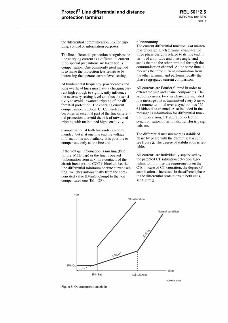
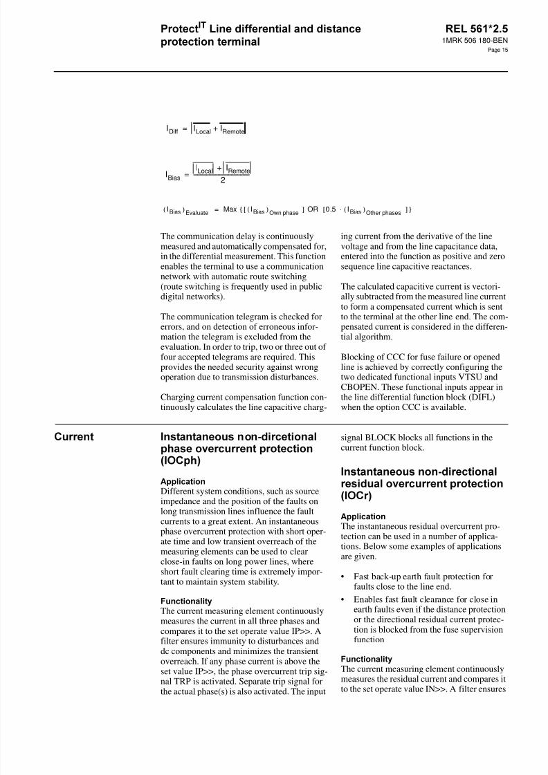
The differential measurement is stabilisedphase by phase with the current scalar sum,see figure 5. The degree of stabilisation is set-table.
All currents are individually supervised bythe patented CT saturation detection algo-rithm, to minimise the requirements on theCTs. In case of CT saturation, the degree ofstabilisation is increased in the affected phasein the differential protections at both ends,see figure 5.
Figure 5: Operating characteristic
8/11/2019 1MRK506180-BEN a en Protect IT Line Differential and Distance Protection Terminal REL 561 2.5
http://slidepdf.com/reader/full/1mrk506180-ben-a-en-protect-it-line-differential-and-distance-protection-terminal 15/94
1MRK 506 180-BEN
Page 15
The communication delay is continuouslymeasured and automatically compensated for,in the differential measurement. This functionenables the terminal to use a communicationnetwork with automatic route switching(route switching is frequently used in publicdigital networks).
The communication telegram is checked forerrors, and on detection of erroneous infor-mation the telegram is excluded from theevaluation. In order to trip, two or three out offour accepted telegrams are required. Thisprovides the needed security against wrongoperation due to transmission disturbances.
Charging current compensation function con-
tinuously calculates the line capacitive charg-
ing current from the derivative of the linevoltage and from the line capacitance data,entered into the function as positive and zerosequence line capacitive reactances.
The calculated capacitive current is vectori-ally subtracted from the measured line currentto form a compensated current which is sentto the terminal at the other line end. The com-pensated current is considered in the differen-tial algorithm.
Blocking of CCC for fuse failure or openedline is achieved by correctly configuring thetwo dedicated functional inputs VTSU andCBOPEN. These functional inputs appear inthe line differential function block (DIFL)
when the option CCC is available.
Different system conditions, such as sourceimpedance and the position of the faults onlong transmission lines influence the faultcurrents to a great extent. An instantaneousphase overcurrent protection with short oper-
ate time and low transient overreach of themeasuring elements can be used to clearclose-in faults on long power lines, whereshort fault clearing time is extremely impor-tant to maintain system stability.
The current measuring element continuouslymeasures the current in all three phases andcompares it to the set operate value IP>>. Afilter ensures immunity to disturbances anddc components and minimizes the transientoverreach. If any phase current is above theset value IP>>, the phase overcurrent trip sig-nal TRP is activated. Separate trip signal forthe actual phase(s) is also activated. The input
signal BLOCK blocks all functions in thecurrent function block.
The instantaneous residual overcurrent pro-tection can be used in a number of applica-tions. Below some examples of applicationsare given.
• Fast back-up earth fault protection forfaults close to the line end.
• Enables fast fault clearance for close inearth faults even if the distance protectionor the directional residual current protec-tion is blocked from the fuse supervisionfunction
The current measuring element continuously
measures the residual current and compares itto the set operate value IN>>. A filter ensures
IDiff ILocal IRemote+=
IBiasILocal IRemote+
2-------------------------------------------=
IBias( )Evaluate Max I Bias( )Own phase[ ] OR 0.5 I Bias( )Other phases⋅[ ] =
8/11/2019 1MRK506180-BEN a en Protect IT Line Differential and Distance Protection Terminal REL 561 2.5
http://slidepdf.com/reader/full/1mrk506180-ben-a-en-protect-it-line-differential-and-distance-protection-terminal 16/94
1MRK 506 180-BEN
Page 16
immunity to disturbances and dc componentsand minimizes the transient overreach. If theresidual current is above the set value IN>>,
the residual overcurrent trip signal TRN isactivated. The general trip signal TRIP isactivated as well. The input signal BLOCKblocks the complete function.
The time delayed overcurrent protection,TOC, operates at different system conditionsfor currents exceeding the preset value and
which remains high for longer than the delaytime set on the corresponding timer. Thefunction can also be used for supervision andfault detector for some other protection func-tions, to increase the security of a completeprotection system. It can serve as a reservefunction for the line distance protection, ifactivated under fuse failure conditions whichhas disabled the operation of the line distanceprotection.
The current measuring element continuouslymeasures the current in all three phases andcompares it to the set operate value IP>. A fil-ter ensures immunity to disturbances and dccomponents and minimizes the transientoverreach. If the current in any of the threephases is above the set value IP>, a commonstart signal STP and a start signal for theactual phase(s) are activated. The timer tP isactivated and the phase overcurrent trip signalTRP is activated after set time. The generaltrip signal TRIP is activated as well.
The input signal BLOCK blocks the function.The input signal BLKTR blocks both trip sig-
nals TRP and TRIP.
The time delayed residual overcurrent protec-tion is intended to be used in solidly and lowresistance earthed systems. The time delayedresidual overcurrent protection is suitable asback-up protection for phase to earth faults,normally tripped by operation of the distanceprotection. The protection function can also
serve as protection for high resistive phase toearth faults.
The residual current measuring element con-tinuously measures the residual current andcompares it with the set operate value IN>. Afilter ensures immunity to disturbances anddc components and minimizes the transientoverreach. If the measured current is abovethe set value IN>, a start signal STN is acti-vated. The timer tN is activated and theresidual overcurrent trip signal TRN is acti-vated after set time. The general trip signalTRIP is activated as well. The input signalBLOCK blocks the function. The input signalBLKTR blocks both trip signals TRN and
TRIP.
The two current/time stages of overcurrentprotection TOC2 improve the possibility toget fast operation for nearby faults by using ahigh set current stage with short time delay.The low current stage is set with appropriatetime delay to get selectivity with the adjacentrelays in the system. In networks with inversetime delayed relays, selectivity is generallybest obtained by using the same type ofinverse time characteristic for all overcurrentrelays.
The current measuring element continuouslymeasures the current in all phases and com-pares it to the set operate value for the twocurrent stages. A filter ensures immunity todisturbances and dc components and mini-mizes the transient overreach. If the current in
any of the three phases is above the set valueI>Low, the start signal for the low currentstage is activated. With setting Characteristic= Def, the timer tLow is activated and the tripsignal TRLS is activated after set time. Ifinverse time delay is selected, the timer tMin-Inv starts when the current is above the setvalue I>Low. If the current also is above theset value I>Inv, the inverse time evaluationstarts. When both time circuits operate, thedefinite time circuit tLow is activated and thetrip signal TRLS is activated after the addi-tional time tLow. If the current is above theset value I>High, the timer tHigh is activatedand the trip signal TRHS is activated after settime.

8/11/2019 1MRK506180-BEN a en Protect IT Line Differential and Distance Protection Terminal REL 561 2.5
http://slidepdf.com/reader/full/1mrk506180-ben-a-en-protect-it-line-differential-and-distance-protection-terminal 17/94
1MRK 506 180-BEN
Page 17
The input signal BLOCK blocks all func-tions. Each current stage can also be individu-ally blocked.
The two current/time stages of the TOC3overcurrent protection, both with optionaldirectional (Forward release or Reverseblock) or non-directional function, improvethe possibility to obtain selective function ofthe overcurrent protection relative otherrelays even in meshed networks. It must be
realized, however, that the setting of a phaseovercurrent protection system in a meshednetwork can be very complicated and a largenumber of fault current calculations areneeded. In some cases, it is not possible toobtain selectivity even when using directionalovercurrent protection. In such cases it is sug-gested to use line differential protection ordistance protection function.
The current measuring element continuouslymeasures the current in all three phases andcompares it to the set operate value for thetwo current stages. A filter ensures immunityto disturbances and dc components and mini-mizes the transient overreach. If the current inany of the three phases is above the set valueI>Low, the start signal for the low currentstage is activated. With setting Characteristic= Def, the timer tLow is activated and the tripsignal TRLS is activated after set time. Ifinverse time delay is selected, the timer tMin-Inv starts when the current is above the setvalue I>Low. If the current also is above theset value I>Inv, the inverse time evaluationstarts. When both time circuits operate, the
definite time circuit tLow is activated and thetrip signal TRLS is activated after set time.
If the current is above the set value I>High,the timer tHigh is activated and the trip signalTRHS is activated after set time.The low andthe high set current stages can individually beset directional or non-directional. Directionalinformation is calculated from positivesequence polarization voltages and the phasecurrents. The polarization voltage containsmemory voltage to ensure directional func-tion at close-in three-phase faults. The direc-tional element relay characteristic angle(RCA) and operate angle are settable in wideranges.
The input signal BLOCK blocks all func-tions. Trip from each current stage can also beindividually blocked.
Use the inverse and definite time delayedresidual overcurrent functions in solidlyearthed systems to get a sensitive and fastfault clearance of phase to earth faults.
The nondirectional protection can be usedwhen high sensitivity for earth fault protec-tion is required. It offers also a very fast back-
up earth fault protection for the part of atransmission line, closest to the substationwith the protection.
The nondirectional residual overcurrent pro-tection can be given a relatively low currentpick-up setting. Thus the protection will besensitive, in order to detect high resistivephase to earth faults.
The directional residual overcurrent protec-tion can be used in a number of applications:
1. Main protection for phase to earth faultson the radial lines in solidly earthed sys-tems. Selectivity is achieved by usingtime delayed function according to prac-tices in the system (definite time delay orsome type of inverse time characteristic).
2. Main protection for phase to earth faultson lines in a meshed solidly earthed sys-tem. The directional function can be usedin an permissive overreach communica-tion scheme or a blocking scheme. In thisapplication the directional residual over-current function is used together with thecommunication logic for residual overcur-
rent protection.3. Back-up protection for phase to earth
faults for lines in solidly earthed systems.By using the directional residual protec-tion as back-up function, the back-up faultclearance time can be kept relatively shorttogether with the maintained selectivity.
4. Etc.
The residual overcurrent protection (TEFdir)measures the residual current of the protectedline. This current is compared to the current
settings of the function. If the residual currentis larger than the setting value a trip signal
8/11/2019 1MRK506180-BEN a en Protect IT Line Differential and Distance Protection Terminal REL 561 2.5
http://slidepdf.com/reader/full/1mrk506180-ben-a-en-protect-it-line-differential-and-distance-protection-terminal 18/94
1MRK 506 180-BEN
Page 18
will be sent to the output after a set delaytime. The time delay can be selected betweenthe definite or inverse possibility.
In order to avoid unwanted trip for trans-former inrush currents, the function isblocked if the second harmonic content of theresidual current is larger than 20% of themeasured residual current.
As on option the residual overcurrent protec-tion can have directional function. The resid-ual voltage is used as a polarizing quantity.This voltage is either derived as the vectorialsum of inputs U1+U2+U3 or as the input U4.The fault is defined to be in the forwarddirection if the residual current component inthe characteristic angle 65° (residual currentlagging the reference voltage, -3U0), is largerthan the set operating current in forwarddirection. The same kind of measurement isperformed also in the reverse direction.
In solidly earthed systems the four step resid-ual overcurrent protection can be used in asimilar way as a distance protection. As themajority of the faults involve earth connec-tion, the protection will be able to clear mostof the faults in these systems. All four stepscan be non-directional or directional.
One example of a normal application of thefour step residual overcurrent protection canbe described as follows: The instantaneousand directional step 1 will normally covermost of the line. The rest of the line is cov-ered by the directional and delayed step 2.Step 2 will also detect and trip earth faults on
the remote busbar. The directional step 3 hasa longer time delay and will act as a selectiveprotection for earth faults with some degreeof fault resistance. The non-directional step 4has the longest delay. This step will detectand clear high resistive earth faults as well asthe majority of series faults.
The four step residual overcurrent protectioncan also be used together with the communi-cation logic for residual overcurrent protec-tion, in order to realize blocking orpermissive overreaching communicationschemes.
The function operates on the basis of theresidual current and voltage measurement.The function has four steps with individualsettings (current, delay, directionality, secondharmonic restrained etc.). Step 1, 2 and 3have independent time delay. The time delayfor step 4 can be selected between definite orinverse mode of operation.
For each step the current is compared to theset current of the step. Further the followingquantities are checked to be used as release orblocking of function from the steps:
• Direction, forward or reverse direction tothe fault. The residual current component
lagging the reference (-3.U0) voltage 65°is derived. If this current component islarger than the directional current setting,forward direction is detected.
• The second harmonic of the residual cur-rent is derived. If this current is largerthan 20/32 % of the total residual current,a signal is given that can be used forblocking of the steps.
If the conditions for function is fulfilled for astep, a trip signal is given after the set timedelay.
In isolated networks or in networks with highimpedance earthing, the phase to earth faultcurrent is significantly smaller than the shortcircuit currents. In addition to this, the magni-tude of the fault current is almost independenton the fault location in the network.
The protection uses the residual current com-
ponent 3I 0 cosϕ, where ϕ is the anglebetween the residual current and the referencevoltage, compensated with a characteristicangle. The characteristic angle is chosen to -90° in an isolated system. The characteristicangle is chosen to 0° in compensated systems.
The function measures the residual currentand voltage. The angle between the residualvoltage and residual current (angle between3I0 and -3U0 i.e U0 is 180 degrees adjusted)is calculated. This angle is used in two func-tions namely first to determine if the fault isin forward or reverse direction, and secondly
8/11/2019 1MRK506180-BEN a en Protect IT Line Differential and Distance Protection Terminal REL 561 2.5
http://slidepdf.com/reader/full/1mrk506180-ben-a-en-protect-it-line-differential-and-distance-protection-terminal 19/94
1MRK 506 180-BEN
Page 19
to calculate the residual current component inthe characteristic angle direction.
The residual current component in the charac-teristic angle direction is compared with theset operating value. If this current componentis larger than the setting this is one criterionfor function of the protection. The residualvoltage is compared to a set operating value.If the measured voltage is larger than the set-ting this is another criterion for the operationof the protection. If both the criteria are ful-filled and the set time delay has elapsed, thefunction will give a trip signal.
Due to the demands on accuracy and sensitiv-ity for this function, special current inputtransformers must be used.
In isolated networks or in networks with highimpedance earthing, the phase to earth faultcurrent is significantly smaller than the shortcircuit currents. In addition to this, the magni-tude of the fault current is almost independenton the fault location in the network.
The protection uses the residual power com-ponent 3U 0 .3I0.cosϕ, where ϕ is the anglebetween the residual current and the referencevoltage, compensated with a characteristicangle. The characteristic angle is chosen to -90° in an isolated system. The characteristicangle is chosen to 0° in compensated systems.
The function measures the residual currentand voltage. The angle between the residualvoltage and residual current is calculated.This angle is used in two functions namely
first to determine if the fault is in forward orreverse direction, and secondly to calculatethe residual power component in the charac-teristic angle direction.
The residual voltage (3U 0) is compared witha setting value. The residual current (3I 0) iscompared to a setting value. The residualpower component in the characteristic angledirection (S N) is compared to a power refer-ence setting. If the power is larger than thesetting this is one criterion for function of theprotection. The voltage and current measure-ment are two other criteria that must be ful-filled for function. The information on poweris the input to a dependent time delay func-
tion. The function will give a trip signal whenall three criteria for function are fulfilled andthe time delay has elapsed.
Due to the demands on accuracy and sensitiv-ity for this function, special current input cir-cuits must be used.
The EFC directional comparison functioncontains logic for blocking overreaching andpermissive overreaching schemes. The func-
tion is applicable together with TEF timedelayed directional residual overcurrent pro-tection in order to decrease the total operatetime of a complete scheme.
One communication channel, which cantransmit an on / off signal, is required in eachdirection. It is recommended to use the com-plementary additional communication logicEFCA, if the weak infeed and/or currentreversal conditions are expected together withpermissive overreaching scheme.
The communication logic for residual over-current protection contains logics for block-ing overreach and permissive overreachschemes.
In the blocking scheme a signal is sent to theremote end of the line if the directional ele-ment, in the directional residual overcurrentprotection (sending end), detects the fault inthe reverse direction. If no blocking signal isreceived and the directional element, in thedirectional residual overcurrent protection(receiving end), detects the fault in the for-
ward direction, a trip signal will be sent aftera settable time delay.
In the permissive overreach scheme a signalis sent to the remote end of the line if thedirectional element, in the directional residualovercurrent protection (sending end), detectsthe fault in the forward direction. If an accel-eration signal is received and the directionalelement, in the directional residual overcur-rent protection (receiving end), detects thefault in the forward direction, a trip signalwill be sent, normally with no time delay. Incase of risk for fault current reversal or weakend infeed, an additional logic can be used totake care of this.
8/11/2019 1MRK506180-BEN a en Protect IT Line Differential and Distance Protection Terminal REL 561 2.5
http://slidepdf.com/reader/full/1mrk506180-ben-a-en-protect-it-line-differential-and-distance-protection-terminal 20/94
1MRK 506 180-BEN
Page 20
The EFCA additional communication logic isa supplement to the EFC scheme communica-tion logic for the residual overcurrent protec-tion.
To achieve fast fault clearing for all earthfaults on the line, the TEF earth-fault protec-tion function can be supported with logic, thatuses communication channels. REx 5xx ter-minals have for this reason available addi-tions to scheme communication logic.
If parallel lines are connected to commonbusbars at both terminals, overreaching per-missive communication schemes can tripunselectively due to fault current reversal.This unwanted tripping affects the healthyline when a fault is cleared on the other line.This lack of security can result in a total lossof interconnection between the two buses.Toavoid this type of disturbance, a fault current-reversal logic (transient blocking logic) canbe used.
Permissive communication schemes for
residual overcurrent protection, can basicallyoperate only when the protection in theremote terminal can detect the fault. Thedetection requires a sufficient minimumresidual fault current, out from this terminal.The fault current can be too low due to anopened breaker or high positive and/or zerosequence source impedance behind this ter-minal. To overcome these conditions, weakend infeed (WEI) echo logic is used.
The reverse directed signal from the direc-tional residual overcurrent function, starts theoperation of a current reversal logic. The out-put signal, from the logic, will be activated, ifthe fault has been detected in reverse direc-tion for more than the tPickUp time set on thecorresponding timers. The tDelay timerdelays the reset of the output signal. The sig-nal blocks the operation of the overreach per-missive scheme for residual current, and thusprevents unwanted operation due to fault cur-rent reversal.
The weak end infeed logic uses normally aforward and reverse signal from the direc-
tional residual overcurrent function. Theweak end infeed logic echoes back thereceived permissive signal, if none of the
directional measuring elements have beenactivated during the last 200 ms. Further, itcan be set to give signal to trip the breaker if
the echo conditions are fulfilled and the resid-ual voltage is above the set operate value for3U0>.
Load currents that exceed the permissiblecontinuous value may cause damage to theconductors and isolation due to overheating.The permissible load current will vary withthe ambient temperature.
The THOL thermal overcurrent functionsupervises the phase currents and provides areliable protection against damage caused byexcessive currents. The temperature compen-sation gives a reliable thermal protection evenwhen the ambient temperature has large vari-ations.
The final temperature rise of an object rela-tive the ambient temperature is proportionalto the square of the current. The rate of tem-perature rise is determined by the magnitudeof the current and the thermal time constantof the object. The same time constant deter-mines the rate of temperature decrease whenthe current is decreased.
The thermal overload function uses the high-est phase current. The temperature change iscontinuously calculated and added to the fig-ure for the temperature stored in the thermalmemory. When temperature compensation isused, the ambient temperature is added to thecalculated temperature rise. If no compensa-tion is used, 20 o C is added as a fixed value.
The calculated temperature of the object isthen compared to the set values for alarm andtrip.
The information on the ambient temperatureis received via a transducer input with forexample 0 - 10 mA or 4 - 20 mA.
The output signal THOL--TRIP has a dura-tion of 50 ms. The output signal THOL--START remains activated as long as the cal-culated temperature is higher than the set tripvalue minus a settable temperature differenceTdReset (hysteresis). The output signalTHOL--ALARM has a fixed hysteresis of5o C.
8/11/2019 1MRK506180-BEN a en Protect IT Line Differential and Distance Protection Terminal REL 561 2.5
http://slidepdf.com/reader/full/1mrk506180-ben-a-en-protect-it-line-differential-and-distance-protection-terminal 21/94
1MRK 506 180-BEN
Page 21
The stub protection operates for faults in theparts of 1 1/2 and ring bus station configura-tions, which cannot be protected by the dis-tance protection function if the line isolatorsare opened. The use of the function can beextended to various other purposes, when athree phase overcurrent protection can oper-ate only under special external conditions.
The function operates as a three phase instan-taneous overcurrent protection. The functionis released when the line disconnector isopen; a normally closed auxiliary contact ofthe line disconnector has to be connected tothe STUB-RELEASE functional input byconfiguration.
The operating level of the overcurrent protec-tion is settable over a wide range.
In many protection applications local redun-dancy is used. One part of the fault clearancesystem is however never duplicated, namely
the circuit breaker. Therefore a breaker fail-ure protection can be used.
The breaker failure protection is initiated bytrip signals from different protection func-tions within or outside the protection termi-
nal. When a trip signal is sent to the breakerfailure protection first, with no or a very shortdelay, a re-trip signal can be sent to the pro-tected breaker. If fault current is flowingthrough the breaker still after a setting time aback-up trip signal is sent to the adjacentbreakers. This will ensure fault clearance alsoif the circuit breaker is out of order.
Breaker failure protection, BFP, providesbackup protection for the primary circuitbreaker if it fails to clear a system fault. It isobtained by checking that fault current per-
sists after a brief time from the operation ofthe object protection and issuing then a threephase trip command to the adjacent circuitbreakers (back-up trip).
Correct operation at evolving faults isensured by phase segregated starting com-mand, phase segregated current check andphase segregated settable timers.
Additionally, the retrip of the faulty circuitbreaker after a settable time is possible. Theretrip can be controlled by current check orcarried out as direct retrip.
The time delayed undervoltage protectionfunction, TUV, is applicable in all situations,where reliable detection of low phase volt-ages is necessary. The function can also beused as a supervision and fault detection
function for some other protection functions,to increase the security of a complete protec-tion system.
The time delayed phase overvoltage protec-tion is used to protect the electrical equip-ment and its insulation against overvoltage bymeasuring three phase voltages. In this way, itprevents the damage to the exposed primary
and secondary equipment in the power sys-tems.
The phase overvoltage protection functioncontinuously measures the three phase volt-ages and initiates the corresponding outputsignals if the measured phase voltages exceedthe preset value (starting) and remain highlonger than the time delay setting on the tim-ers (trip). This function also detects thephases which caused the operation.
The residual overvoltage protection functionis mainly used in distribution networks,mainly as a backup protection for the residualovercurrent protection in the line feeders, tosecure the disconnection of earth-faults.
The residual overvoltage protection functioncalculates the residual voltage (3U0) from themeasuring three phase voltages and initiates
8/11/2019 1MRK506180-BEN a en Protect IT Line Differential and Distance Protection Terminal REL 561 2.5
http://slidepdf.com/reader/full/1mrk506180-ben-a-en-protect-it-line-differential-and-distance-protection-terminal 22/94
1MRK 506 180-BEN
Page 22
the corresponding output signals if the resid-ual voltage is larger than the preset value
(starting) and remains high longer than thetime delay setting (trip).
The main purpose of the BRC broken con-ductor check function is the detection of bro-ken conductors on protected power lines andcables (series faults). It is also able to detectinterruptions in the secondary current cir-cuits.
The BRC function detects a broken conductorcondition by detecting the non symmetry
between currents in the three phases. It doesthis by measuring the difference between themaximum and minimum phase currents, i.e. itcompares the magnitude of the minimum cur-rent with that of the maximum current, andgives an output if the minimum current is lessthan 80% of the maximum current for a settime interval. At the same time, the highestcurrent must be higher than a set percentageof the terminal rated current.
The loss of voltage detection, LOV, is suit-able for use in networks with an automaticrestoration function. The LOV functionissues a three-pole trip command to the cir-cuit breaker, if all three phase voltages fallbelow the set value for a time longer than 7seconds, and the circuit breaker remainsclosed.
The operation of LOV function is based online voltage measurement. The function isprovided with a logic, which automaticallyrecognises if the line was restored for at leastthree seconds before starting the seven sec-onds timer. Additionally, the function is auto-matically blocked if only one or two phasevoltages have been detected low for morethan 10 seconds. The LOV function operatesagain only if the line has been fully energised.
Operation of LOV function is also inhibitedby fuse failure and open circuit breaker infor-mation signals, by their connection to dedi-cated inputs of the function block.
The operation of the function is supervised bythe fuse-failure function and the informationabout the closed position of the associatedcircuit breaker.
The overload protection, OVLD, preventsexcessive loading of power transformers,lines and cables.
Alternative application is the detection of pri-mary current transformer overload, as theyusually can withstand a very small currentbeyond the rated value.
The function continuously measures the threephase currents flowing through the terminal.If any of the three currents is beyond the pre-
set overcurrent threshold for a time longerthan the preset value, a trip signal is acti-vated.
The main purpose of the dead line detectionis to provide different protection, control andmonitoring functions with the status of theline, i.e whether or not it is connected to therest of the power system.
The dead line detection function continuouslymeasures all three phase currents and phasevoltages of a protected power line. The line isdeclared as dead (not energized) if all threemeasured currents and voltages fall below thepreset values for more than 200 ms.
Sudden events in an electrical power system
such as large jumps in load, fault occurrenceor fault clearance, can cause oscillations
referred to as power swings. In a recoverablesituation, the power swings will decay andstable operation will be resumed; in a non-recoverable situation, the power swings
become so severe that the synchronism islost, a condition referred to as pole slipping.

8/11/2019 1MRK506180-BEN a en Protect IT Line Differential and Distance Protection Terminal REL 561 2.5
http://slidepdf.com/reader/full/1mrk506180-ben-a-en-protect-it-line-differential-and-distance-protection-terminal 23/94
1MRK 506 180-BEN
Page 23
The main purpose of the PSP pole slip protec-tion is to detect, evaluate, and take therequired action for pole slipping occurrences
in the power system.
The PSP function comprises an inner and anouter quadrilateral measurement characteris-tic. It detects oscillations in the power systemby measuring the time it takes the transientimpedance to pass through the impedancearea between the outer and the inner charac-teristics. Oscillations are identified by transi-tion times longer than timer settings. Theimpedance measuring principle is the same asthat used for the distance protection zones.The impedance and the transient impedance
time are measured in all three phases sepa-rately. One-out-of-three or two-out-of-threeoperating modes can be selected permanentlyor adaptively according to the specific systemoperating conditions.
Oscillations with an oscillation period as lowas 200 ms (i.e. with a slip frequency as highas 10% of the rated frequency on a 50 Hzbasis) can be detected for normal systemoperating conditions, as well as during thedead time of a single-pole automatic reclos-ing cycle. Different timers are used for initialand consecutive pole slips, securing a highdegree of differentiation between oscillationand fault conditions.
It is possible to inhibit the ocsillation detectedoutput on detection of earth fault current.This can be used to release the operation ofthe distance protection function for earthfaults during power oscillation conditions.
The PSP function has two tripping areas.These are located within the operating area,which is located within the inner characteris-tic. On detection of a new oscillation, the
activation of a trip output will depend on theapplied settings. These determine the direc-tion of the transition for which tripping is per-mitted, whether tripping will occur on entryof the measured impedance into a trippingarea, or on its exit from the tripping area, andthrough which tripping area the transitionmust be measured for tripping to occur. Theapplied settings also determine the number ofpole slips required before the trip output isissued.
The low active power protection function(LAPP) can be used wherever a “low activepower” signal is needed. The main applica-tion is as a local criterion to increase securitywhen transfer trips are used.
In many power systems transfer trips areused, i.e. a trip criterion in one substation willbe transferred to an adjacent substation viasome sort of communication system. For suchsolutions there is always a risk that a falsetransfer trip signal is generated in the com-munication system and causes an unwantedtrip. In order to prevent such a scenario alocal criterion can be added in the substationwhere the trip is intended to take place. Sucha local criterion could be low active power ona line, which, in a correct sequence, is discon-nected in the remote end.
The low active power function measures theactive power separately in each phase. It alsodetermines whether the power flow istowards or from the relay point as long as themeasured current and voltage are higher than
the minimum operating values. The operationbecomes automatically non-directional, if themeasured current decreases under the mini-mum value and the measured voltage remainshigher.
Two operating levels are setable independentof each other regarding their operating val-ues, directionality and time delay. It is possi-ble to use their start and trip signals withinthe configuration of the terminal.
The combined low active and reactive powerprotection function (LARP) can be usedwherever a “low reactive power” signal isneeded. The main application is as a local cri-terion to increase security when transfer tripsare used. The design gives the user a possibil-ity to increase the sensitivity for high levelsof active power. The tripping criterion is afunction of the set value and the actual activepower according to:

8/11/2019 1MRK506180-BEN a en Protect IT Line Differential and Distance Protection Terminal REL 561 2.5
http://slidepdf.com/reader/full/1mrk506180-ben-a-en-protect-it-line-differential-and-distance-protection-terminal 24/94
1MRK 506 180-BEN
Page 24
(Equation 1)In many power systems transfer trips areused, i.e. a trip criterion in one substation willbe transferred to an adjacent substation viasome sort of communication system. For suchsolutions there is always a risk that a falsetransfer trip signal is generated in the com-munication system and causes an unwantedtrip. In order to prevent such a scenario alocal criterion can be added in the substationwhere the trip is intended to take place. Sucha local criterion could be low reactive poweron a line, which, in a correct sequence, is dis-connected in the remote end.
The low active and reactive power functionmeasures the active and the reactive powerseparately in each phase. It also determineswhether the power flow is towards or fromthe relay point as long as the measured cur-rent and voltage are higher than the minimumoperating values. The operation becomesautomatically nondirectional, if the measuredcurrent decreases under the minimum valueand the measured voltage remains higher.
Two operating levels are settable independentof each other regarding their operating val-ues, directionality and time delay. It is possi-ble to use their start and trip signals withinthe configuration of a terminal.
The high active power protection function(HAPP) can be used wherever a “high activepower” signal is needed. There is a number ofapplications for the high active power protec-tion, wherever active power flow has to belimited or certain actions have to be takenwhen the active power exceeds specific val-ues. One such example is arming of generatorrejection schemes due to certain active powertransmission levels within a certain corridor.
The high active power function measures theactive power separately in each phase. It alsodetermines whether the power flow istowards or from the relay point as long as themeasured current and voltage are higher than
the minimum operating values.
Two operating levels are setable independentof each other regarding their operating val-ues, directionality and time delay. It is possi-
ble to use their start and trip signals withinthe configuration of the terminal.
The combined high active and reactive powerprotection function (HARP) can be usedwherever a “high reactive power” signal isneeded. The design gives the user a possibil-ity to increase the sensitivity for high levelsof active power. The tripping criterion is a
function of the set value and the actual activepower according to:
(Equation 2)Typically, high reactive power output fromgenerators, connected to transmission grids,is used as an important signal in system pro-tection schemes to counteract voltage insta-bility.
The high active and reactive power functionmeasures the active and the reactive powerseparately in each phase. It also determineswhether the power flow is towards or fromthe relay point as long as the measured cur-rent and voltage are higher than the minimumoperating values.
The operational characteristic is according to:
Q>Qset+tan(k)*abs(P).
Two operating levels are settable independent
of each other regarding their operating val-ues, directionality and time delay. It is possi-ble to use their start and trip signals withinthe configuration of a terminal.
The sudden change in current protectionfunction (SCC1) can be used wherever a sud-den change in current can be used to improvethe overall functionality of the protection sys-
tem. The main application is as a local crite-rion to increase security when transfer tripsare used.
Q trip Q set α+ P⋅=
Q trip Q set α+ P⋅=
8/11/2019 1MRK506180-BEN a en Protect IT Line Differential and Distance Protection Terminal REL 561 2.5
http://slidepdf.com/reader/full/1mrk506180-ben-a-en-protect-it-line-differential-and-distance-protection-terminal 25/94
1MRK 506 180-BEN
Page 25
In many power systems transfer trips areused, i.e. a trip criterion in one substation willbe transferred to an adjacent substation via
some sort of communication system. For suchsolutions there is always a risk that a falsetransfer trip signal is generated in the com-munication system and causes an unwantedtrip. In order to prevent such a scenario alocal criterion can be added in the substationwhere the trip is intended to take place. Sucha local criterion could be a sudden change incurrent on a line, which, in a correctsequence, is disconnected in the remote end.
The amplitude of the difference between themagnitudes of two consecutive cycles is
derived by means of the fourier coefficientsof the fundamental signal.
The integration time is one power systemcycle.
The change in current is compared to a set-ting value to create the start and, after a timedelay, the trip signal.
The sudden change in residual current protec-tion function (SCRC) can be used wherever asudden change in residual current can be usedto improve the overall functionality of theprotection system. The main application is asa local criterion to increase security whentransfer trips are used.
Whenever an earth-fault occurs, or a circuit-breaker get stuck in one phase, a residual cur-rent appears, that can be used to increase thesecurity of transfer trip arrangements.
The amplitude of the difference between themagnitudes of two consecutive cycles isderived by means of the fourier coefficientsof the fundamental signal.
The integration time is one power systemcycle.
The change in residual current is compared toa setting value to create the start and, after atime delay, the trip signal.
The sudden change in voltage protectionfunction (SCV) can be used wherever a sud-den change in voltage can be used to improvethe overall functionality of the protection sys-tem.
One application is as a local criterion toincrease security when transfer trips are used.Another application is to recognize networktopology changes that cause sudden changesin voltage. Also faults, tap-changer opera-tions, shunt device switching, etc., cause sud-den changes in voltage that can be capturedby the SCV function.
The amplitude of the difference between themagnitudes of two consecutive cycles isderived by means of the fourier coefficientsof the fundamental signal.
The integration time is one power systemcycle.
The change in voltage is compared to a set-ting value to create a start signal and, after a
time delay, a trip signal.
The overvoltage protection function (OVP)can be used wherever a "high voltage" signalis needed. The function can be used for appli-cations where a high voltage is the result ofan event that has to be indicated, or actions toreduce the time with high voltage levels arerequired.
One application example is to take actions toquickly reduce high voltage levels by switch-ing out shunt capacitors or switching in shuntreactors, in case of a long transmission con-nected in one end only.
The overvoltage protection function (OVP)measures all three phase voltages on a pro-tected power line. The measured voltage sig-nals are extensively filtered, to secure highaccuracy of the measurement. Each of twoindependent voltage measuring stages has itsown, independently settable time delay.

8/11/2019 1MRK506180-BEN a en Protect IT Line Differential and Distance Protection Terminal REL 561 2.5
http://slidepdf.com/reader/full/1mrk506180-ben-a-en-protect-it-line-differential-and-distance-protection-terminal 26/94
1MRK 506 180-BEN
Page 26
The resetting ratio of the function is settable,to adjust the operation as much as possible tothe expected system overvoltage conditions.
This expecially when the big shunt reactorsare used in the network to control the systemovervoltages.
The undercurrent protection function (UCP)can be used whenever a "low current" signalis needed. The main application is as a localcriterion to increase security when transfertrips are used.
In many power systems transfer trips areused, i.e. a trip criterion in one substation willbe transferred to an adjacent substation viasome sort of communication system. For suchsolutions there is always a risk that a falsetransfer trip signal is generated in the com-munication system and causes an unwantedtrip. In order to prevent such a scenario alocal criterion can be added in the substationwhere the trip is intended to take place. Sucha local criterion could be low current on aline, which, in a correct sequence, is discon-nected in the remote end.
When any phase current decreases under thesetpoint value, a start signal is issued.
When a start signal is activated and the car-rier received signal is true, a trip signal isissued after a settable time delay.
The overcurrent protection function (OCP)can be used wherever a "high current" signal
is needed. There is a number of applicationsfor the high current protection, wherever cur-rent has to be limited, or certain actions have
to be taken when the current exceeds specificvalues.
The amplitude of the phase currents are cal-culated by means Fourier filtering. When anyof the phase currents are larger than the set-ting values for the high-set step or the low-setstep, the corresponding start signal will beactivated. At the same time the correspondingtimer will be started. After the timer for thestep has elapsed and there is a CR signal, atrip signal will be activated.
The residual overcurrent protection function(ROCP) can be used wherever a high residualcurrent signal is needed. There is a number ofapplications for the high residual current pro-tection, most of them related to earth faults inlow impedance earthed systems. One exam-ple is to use the residual overcurrent protec-tion as a simple earth fault protection, as aback-up for the primary earth fault protectionincluded in the line distance protection.
The amplitude of the residual current is calcu-lated by means Fourier filtering. When theresidual current is larger than the settingvalue for the high-set step or the low set step,the corresponding start signal will be acti-vated. At the same time the correspondingtimer will be started. After the timer for thestep has elapsed and there is a CR signal, atrip signal will be activated.
Faulty information about current flows in aprotected element might influence the secu-rity (line differential protection) or depend-ability (line distance protection) of acomplete protection system.
The main purpose of the current circuit super-vision function is to detect different faults inthe current secondary circuits and influence
the operation of corresponding main protec-tion functions.
The signal can be configured to block differ-ent protection functions or initiate an alarm.
The function compares the sum of the threephase currents from one current transformercore with a reference zero sequence currentfrom another current transformer core.
The function issues an output signal when thedifference is greater than the set value.
8/11/2019 1MRK506180-BEN a en Protect IT Line Differential and Distance Protection Terminal REL 561 2.5
http://slidepdf.com/reader/full/1mrk506180-ben-a-en-protect-it-line-differential-and-distance-protection-terminal 27/94
1MRK 506 180-BEN
Page 27
The fuse failure supervision function, FUSE,continuously supervises the ac voltage cir-cuits between the voltage instrument trans-formers and the terminal. Different outputsignals can be used to block, in case of faultsin the ac voltage secondary circuits, the oper-ation of the distance protection and othervoltage-dependent functions, such as the syn-chro-check function, undervoltage protection,etc.
Different measurement principles are avail-able for the fuse failure supervision function.
The FUSE function based on zero sequencemeasurement principle, is recommended indirectly or low impedance earthed systems.
The FUSE function based on the negativesequence measurement principle is recom-mended in isolated or high impedance earthedsystems.
A criterion based on delta current and deltavoltage measurements can be added to theFUSE function in order to detect a threephase fuse failure, which in practice is more
associated with voltage transformer switchingduring station operations.
The FUSE function based on the negativesequence measurement principle continu-ously measures the negative sequence voltageand current in all three phases. It operates ifthe measured negative sequence voltageincreases over the preset operating value, andif the measured negative sequence currentremains below the preset operating value.
The FUSE function based on the zerosequence measurement principle continu-ously measures the zero sequence current andvoltage in all three phases. It operates if themeasured zero sequence voltage increasesover preset operating value, and if the mea-
sured zero sequence current remains belowthe preset operating value.
The di/dt and du/dt algorithm, detects a fusefailure if a sufficient negative change in volt-age amplitude without a sufficient change incurrent amplitude is detected in each phaseseparately. This check is performed if the cir-cuit breaker is closed. Information about thecircuit breaker position is brought to the func-tion input CBCLOSED through a binaryinput of the terminal.
Three output signals are available. The firstdepends directly on the voltage and currentmeasurement. The second depends on theoperation of the dead line detection function,to prevent unwanted operation of the distanceprotection if the line has been deenergisedand energised under fuse failure conditions.The third depends on the loss of all threemeasured voltages. A special function inputserves the connection to the auxiliary contactof a miniature circuit breaker, MCB (if used),to secure correct operation of the function onsimultaneous interruption of all three mea-sured phase voltages also when the additionaldelta current and delta voltage algorithm isnot present in the function block.
The main purpose of the voltage transformersupervision function is to indicate failure inthe measuring voltage from a capacitive volt-age transformer.
The voltage transformer supervision functionchecks all of the three phase-phase voltagesand the residual voltage. If the residual volt-
age exceeds the setpoint value and any of thephase-phase voltages is higher than 80% ofthe rated phase-phase voltage the output isactivated after a settable time delay.
The terminals may be provided with a func-tion to receive signals either from a substa-
tion automation system (SMS and/or SCS) orfrom the local human-machine interface,
HMI. That receiving function block has 16outputs that can be used, for example, to con-trol high voltage apparatuses in switchyards.For local control functions, the local HMI canalso be used. Together with the configurationlogic circuits, the user can govern pulses or
steady output signals for control purposeswithin the terminal or via binary outputs.
8/11/2019 1MRK506180-BEN a en Protect IT Line Differential and Distance Protection Terminal REL 561 2.5
http://slidepdf.com/reader/full/1mrk506180-ben-a-en-protect-it-line-differential-and-distance-protection-terminal 28/94
1MRK 506 180-BEN
Page 28
The single command function consists of afunction block CD for 16 binary output sig-nals.
The output signals can be of the types Off,Steady, or Pulse. The setting is done on theMODE input, common for the whole block,from the CAP 531 configuration tool.
The outputs can be individually controlledfrom the operator station, remote-controlgateway, or from the local HMI. Each outputsignal can be given a name with a maximumof 13 characters from the CAP 531 configura-tion tool.
The output signals, here OUT1 to OUT16,are then available for configuration to built-infunctions or via the configuration logic cir-cuits to the binary outputs of the terminal.
The main purpose of the synchrocheck func-tion is to provide controlled closing of circuitbreakers in interconnected networks.
The main purpose of the energizing checkfunction is to facilitate the controlled recon-nection of a disconnected line or bus to,respectively, an energized bus or line.
The main purpose of the synchronizing func-tion is to provide controlled closing of circuitbreakers when two asynchronous systems aregoing to be connected. It is used for slip fre-quencies that are larger than those for synch-rocheck.
The synchronizing function is only available
together with the synchrocheck and energiz-ing check functions.
To meet the different application arrange-ments, a number of identical SYN functionblocks may be provided within a single termi-nal. The number of these function blocks thatmay be included within any given terminaldepends on the type of terminal. Therefore,the specific circuit breaker arrangements thatcan be catered for, or the number of bays of aspecific arrangement that can be catered for,depends on the type of terminal.
The synchrocheck function measures the con-ditions across the circuit breaker and com-pares them to set limits. The output is onlygiven when all measured conditions aresimultaneously within their set limits.
The energizing check function measures thebus and line voltages and compares them toboth high and low threshold detectors. Theoutput is only given when the actual mea-sured conditions match the set conditions.
The synchronizing measures the conditionsacross the circuit breaker, and also determinesthe angle change during the closing delay ofthe circuit breaker from the measured slip fre-
quency. The output is only given when allmeasured conditions are simultaneouslywithin their set limits. The issue of the outputis timed to give closure at the optimal time.
For single circuit breaker arrangements, theSYN function blocks have the capability tomake the necessary voltage selection. For sin-gle circuit breaker arrangements, selection ofthe correct voltage is made using auxiliarycontacts of the bus disconnection.
The majority of power line faults are transientin nature, i.e. they do not recur when the lineis re-energized following disconnection. Themain purpose of the AR automatic reclosingfunction is to automatically return powerlines to service following their disconnectionfor fault conditions.
Especially at higher voltages, the majority ofline faults are single-phase-to-earth. Faultsinvolving all three phases are rare. The mainpurpose of the single- and two-pole automaticreclosing function, operating in conjunctionwith a single- and two-pole tripping capabil-ity, is to limit the effect to the system of faultsinvolving less than all three phases. This isparticularly valuable for maintaining systemstability in systems with limited meshing orparallel routing.
The AR function is a logical function built upfrom logical elements. It operates in conjunc-tion with the trip output signals from the line
protection functions, the OK to close outputsignals from the synchrocheck and energizing
8/11/2019 1MRK506180-BEN a en Protect IT Line Differential and Distance Protection Terminal REL 561 2.5
http://slidepdf.com/reader/full/1mrk506180-ben-a-en-protect-it-line-differential-and-distance-protection-terminal 29/94
1MRK 506 180-BEN
Page 29
check function, and binary input signals. Thebinary input signals can be for circuit breakerposition/status or from other external protec-
tion functions.Of the six reclosing programs, one providesfor three-pole reclosing only, while the othersprovide for single- and two-pole reclosing as
well. For the latter, only the first shot may besingle- or two-pole. All subsequent shots upto the maximum number will be three-pole.
For some of the programs, depending on theinitial trip, no shot, or only one shot, will bepermitted irrespective of the number of shotsselected.
The main purpose of the TR trip logic func-tion is to serve as a single node throughwhich all tripping for the entire terminal isrouted.
The main purpose of the single- and two-poleextension to the basic three-pole trippingfunction is to cater for applications where, forreasons of system stability, single-pole trip-ping is required for single-phase faults, and/ or two-pole tripping is required for two-phasefaults, e.g. on double circuit parallel lines.
The minimum duration of a trip output signalfrom the TR function is settable.
The TR function has a single input throughwhich all trip output signals from the protec-tion functions within the terminal, or fromexternal protection functions via one or moreof the terminal’s binary inputs, are routed. Ithas a single trip output for connection to oneor more of the terminal’s binary outputs, aswell as to other functions within the terminalrequiring this signal.
The expanded TR function for single- andtwo-pole tripping has additional phase segre-gated inputs for this, as well as inputs forfaulted phase selection. The latter inputs
enable single- and two-pole tripping for thosefunctions which do not have their own phaseselection capability, and therefore which have
just a single trip output and not phase segre-gated trip outputs for routing through thephase segregated trip inputs of the expandedTR function. The expanded TR function hastwo inputs for these functions, one for imped-ance tripping (e.g. carrier-aided tripping com-mands from the scheme communicationlogic), and one for earth fault tripping (e.g.
tripping output from a residual overcurrentprotection). Additional logic secures a three-pole final trip command for these protectionfunctions in the absence of the required phaseselection signals.
The expanded TR function has three trip out-puts, one per phase, for connection to one ormore of the terminal’s binary outputs, as wellas to other functions within the terminalrequiring these signals.
The expanded TR function is equipped withlogic which secures correct operation forevolving faults as well as for reclosing on topersistent faults. A special input is also pro-vided which disables single- and two-poletripping, forcing all tripping to be three-pole.
Breaker pole position discordance can occuron the operation of a breaker with indepen-dent operating gears for the three poles. Thereason may be an interruption in the closingor trip coil circuit, or a mechanical failureresulting in a stuck breaker pole. A pole dis-cordance can be tolerated for a limited time,for instance during a single-phase trip-reclosecycle. The pole discordance function detectsa breaker pole discordancy not generated byauto-reclose cycle and issues a trip signal forthe circuit breaker.
The operation of the pole discordance logic,PD, is based on checking the position of thebreaker auxiliary contacts. Three parallel nor-mally open contacts in series with three nor-mally closed contacts in parallel of therespective breaker poles form a condition ofpole discordance, connected to a binary inputdedicated for the purpose.

8/11/2019 1MRK506180-BEN a en Protect IT Line Differential and Distance Protection Terminal REL 561 2.5
http://slidepdf.com/reader/full/1mrk506180-ben-a-en-protect-it-line-differential-and-distance-protection-terminal 30/94
8/11/2019 1MRK506180-BEN a en Protect IT Line Differential and Distance Protection Terminal REL 561 2.5
http://slidepdf.com/reader/full/1mrk506180-ben-a-en-protect-it-line-differential-and-distance-protection-terminal 31/94
1MRK 506 180-BEN
Page 31
The terminals may be provided with a func-tion to receive signals either from a substa-tion automation system or from otherterminals via the interbay bus. That receivingfunction block has 16 outputs that can beused, together with the configuration logiccircuits, for control purposes within the ter-minal or via binary outputs. When it is usedto communicate with other terminals, theseterminals must have a corresponding eventfunction block to send the information.
One multiple command function block CM01with fast execution time also named
and/or 79 multiple command function blocksCM02-CM80 with slower execution time areavailable in the REx 5xx terminals as options.
The output signals can be of the types Off,Steady, or Pulse. The setting is done on theMODE input, common for the whole block,
from the CAP 531 configuration tool.The multiple command function block has 16outputs combined in one block, which can becontrolled from the operator station or fromother terminals. One common name for theblock, with a maximum of 19 characters, isset from the configuration tool CAP 531.
The output signals, here OUT1 to OUT16,are then available for configuration to built-infunctions or via the configuration logic cir-cuits to the binary outputs of the terminal.
The command function also has a supervisionfunction, which sets the output VALID to 0 ifthe block did not receive data within a config-ured INTERVAL time.
Use the disturbance report to provide the net-work operator with proper information aboutdisturbances in the primary network. The
function comprises several subfunctionsenabling different types of users to access rel-evant information in a structured way.
Select appropriate binary signals to triggerthe red HMI LED to indicate trips or otherimportant alerts.
The disturbance report collects data fromeach subsystem for up to ten disturbances.The data is stored in nonvolatile memory,used as a cyclic buffer, always storing the lat-est occurring disturbances. Data is collected
during an adjustable time frame, the collec-tion window. This window allows for datacollection before, during and after the fault.
The collection is started by a trigger. Anybinary input signal or function block outputsignal can be used as a trigger. The analogsignals can also be set to trigger the data col-lection. Both over levels and under levels areavailable. The trigger is common for all sub-systems, hence it activates them all simulta-neously.
A triggered report cycle is indicated by theyellow HMI LED, which will be lit. Binarysignals may also be used to activate the red
HMI LED for additional alerting of fault con-ditions. A disturbance report summary can beviewed on the local HMI.
Use the indications list to view the state ofbinary signals during the fault. All binaryinput signals to the disturbance report func-tion are listed.
The indications list tracks zero-to-onechanges of binary signals during the faultperiod of the collection window. This meansthat constant logic zero, constant logic one orstate changes from logic one to logic zerowill not be visible in the indications list. Sig-nals are not time tagged. In order to be listedin the indications list the:
1. signal must be connected to the DRPfunction blocks, (DRP1, DRP2, DRP3).
2. setting parameter, IndicationMask, for theinput must be set to Show.
Output signals of other function blocks of theconfiguration will be listed by the signalname listed in the corresponding signal list.Binary input signals are listed by the namedefined in the configuration.
The indications can be viewed on the localHMI and via SMS.
8/11/2019 1MRK506180-BEN a en Protect IT Line Differential and Distance Protection Terminal REL 561 2.5
http://slidepdf.com/reader/full/1mrk506180-ben-a-en-protect-it-line-differential-and-distance-protection-terminal 32/94
1MRK 506 180-BEN
Page 32
Use the disturbance recorder to record analogand binary signals during fault conditions inorder to analyze disturbances. The analysismay include fault severity, fault duration andprotection performance. Replay the recordeddata in a test set to verify protection perfor-mance.
The disturbance recorder records both analogand binary signal information and up to tendisturbances can be recorded.
Analog and digital signals can be used as trig-gers. A trigger signal does not need to berecorded.
A trigger is generated when the analog signalmoves under and/or over set limit values. Thetrig level is compared to the signal’s averagepeak-to-peak value, making the functioninsensible to DC offset. The trig conditionmust occur during at least one full period, thatis, 20 ms for a 50 Hz network.
The recorder continuously records data in acyclic buffer capable of storing the amount of
data generated during the set pre-fault time ofthe collection window. When triggered, thepre-fault data is saved and the data for thefault and post-fault parts of the collectionwindow is recorded.
The RAM area for temporary storage ofrecorded data is divided into subareas, one foreach recording. The size of a subarea dependson the set recording times. There is sufficientmemory for four consecutive recordings witha maximum number of analog channelsrecorded and with maximum time settings.Should no subarea be free at a new distur-bance, the oldest recording is overwritten.
When a recording is completed, the postrecording process:
• merges the data for analog channels withcorresponding data for binary signalsstored in an event buffer
• compresses the data without loosing anydata accuracy
• stores the compressed data in a non-vola-tile memory
The disturbance recordings can be viewed viaSMS or SCS.
Use the event recorder to obtain a list ofbinary signal events that occurred during thedisturbance.
When a trigger condition for the disturbancereport is activated, the event recorder collectstime tagged events from the 48 binary signalsthat are connected to disturbance report andlists the changes in status in chronologicalorder. Each list can contain up to 150 timetagged events that can come from both inter-nal logic signals and binary input channelsand up to ten disturbances can be recorded.Events are recorded during the total recordingtime which depends on the set recordingtimes and the actual fault time.
Events can be viewed via SMS and SCS.
An accurate fault locator is an essential com-plement to the line protection. The fault loca-tor provides distance to fault together withinformation about the measuring loop that has
been used in the calculation.
Reliable information on fault location reducesthe outage time and minimises the need forpatrolling.
The function has limitations for applicationswith series compensated lines.
The fault locator can be started by any inter-nal or external binary signal. Pre-fault andfault phasors of currents and voltages, thatwere filtered from disturbance data storedinto digital sample buffers, are then used forthe distance to fault calculation. The phaseselective signals from the built-in protectionfunctions provide the necessary informationfor the selection of the loop to be used for thecalculation. It is also possible to use the exter-nal phase selection information.
For the distance to fault calculation, a linemodelling algorithm that takes into accountthe sources at both ends of the line, is used. Inthis way, the influence of the load current, theinfeed from the remote end and the fault
resistance, can be compensated for, resultingin a highly accurate calculation.
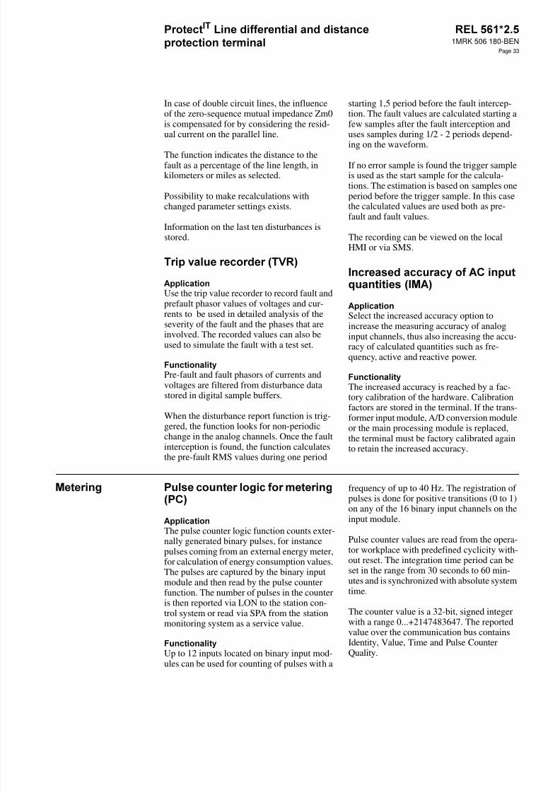
8/11/2019 1MRK506180-BEN a en Protect IT Line Differential and Distance Protection Terminal REL 561 2.5
http://slidepdf.com/reader/full/1mrk506180-ben-a-en-protect-it-line-differential-and-distance-protection-terminal 33/94
1MRK 506 180-BEN
Page 33
In case of double circuit lines, the influenceof the zero-sequence mutual impedance Zm0is compensated for by considering the resid-
ual current on the parallel line.The function indicates the distance to thefault as a percentage of the line length, inkilometers or miles as selected.
Possibility to make recalculations withchanged parameter settings exists.
Information on the last ten disturbances isstored.
Use the trip value recorder to record fault andprefault phasor values of voltages and cur-rents to be used in detailed analysis of theseverity of the fault and the phases that areinvolved. The recorded values can also beused to simulate the fault with a test set.
Pre-fault and fault phasors of currents andvoltages are filtered from disturbance datastored in digital sample buffers.
When the disturbance report function is trig-gered, the function looks for non-periodicchange in the analog channels. Once the faultinterception is found, the function calculatesthe pre-fault RMS values during one period
starting 1,5 period before the fault intercep-tion. The fault values are calculated starting afew samples after the fault interception and
uses samples during 1/2 - 2 periods depend-ing on the waveform.
If no error sample is found the trigger sampleis used as the start sample for the calcula-tions. The estimation is based on samples oneperiod before the trigger sample. In this casethe calculated values are used both as pre-fault and fault values.
The recording can be viewed on the localHMI or via SMS.
Select the increased accuracy option toincrease the measuring accuracy of analoginput channels, thus also increasing the accu-racy of calculated quantities such as fre-quency, active and reactive power.
The increased accuracy is reached by a fac-tory calibration of the hardware. Calibrationfactors are stored in the terminal. If the trans-former input module, A/D conversion moduleor the main processing module is replaced,the terminal must be factory calibrated againto retain the increased accuracy.
The pulse counter logic function counts exter-nally generated binary pulses, for instance
pulses coming from an external energy meter,for calculation of energy consumption values.The pulses are captured by the binary inputmodule and then read by the pulse counterfunction. The number of pulses in the counteris then reported via LON to the station con-trol system or read via SPA from the stationmonitoring system as a service value.
Up to 12 inputs located on binary input mod-ules can be used for counting of pulses with a
frequency of up to 40 Hz. The registration ofpulses is done for positive transitions (0 to 1)on any of the 16 binary input channels on theinput module.
Pulse counter values are read from the opera-tor workplace with predefined cyclicity with-out reset. The integration time period can beset in the range from 30 seconds to 60 min-utes and is synchronized with absolute systemtime.
The counter value is a 32-bit, signed integerwith a range 0...+2147483647. The reportedvalue over the communication bus containsIdentity, Value, Time and Pulse CounterQuality.
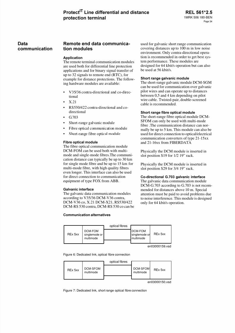
8/11/2019 1MRK506180-BEN a en Protect IT Line Differential and Distance Protection Terminal REL 561 2.5
http://slidepdf.com/reader/full/1mrk506180-ben-a-en-protect-it-line-differential-and-distance-protection-terminal 34/94
1MRK 506 180-BEN
Page 34
The remote terminal communication modulesare used both for differential line protectionapplications and for binary signal transfer ofup to 32 signals to remote end (RTC), forexample for distance protections. The follow-ing hardware modules are available:
• V35/36 contra-directional and co-direc-tional
• X.21• RS530/422 contra-directional and co-
directional
• G.703• Short-range galvanic module• Fibre optical communication module• Short-range fibre optical module
The fibre optical communication moduleDCM-FOM can be used both with multi-mode and single-mode fibres.The communi-cation distance can typically be up to 30 kmfor single mode fibre and be up to 15 km formulti-mode fibre, with high quality fibreseven longer. This interface can also be usedfor direct connection to communicationequipment of type FOX from ABB.
The galvanic data communication modulesaccording to V35/36 DCM-V36 contra,DCM-V36 co, X.21 DCM-X21, RS530/422DCM-RS 530 contra, DCM-RS 530 co can be
used for galvanic short range communicationcovering distances up to 100 m in low noiseenvironment. Only contra-directional opera-
tion is recommended in order to get best sys-tem performance. These modules aredesigned for 64 kbit/s operation but can alsobe used at 56 kbit/s.
The short-range galvanic module DCM-SGMcan be used for communication over galvanicpilot wires and can operate up to distancesbetween 0,5 and 4 km depending on pilotwire cable. Twisted-pair, double-screenedcable is recommended.
The short-range fibre optical module DCM-SFOM can only be used with multi-modefibre .The communication distance can nor-mally be up to 5 km. This module can also beused for direct connection to optical/electricalcommunication converters of type 21-15xxand 21-16xx from FIBERDATA
Physically the DCM module is inserted inslot position S19 for 1/2 19” rack.
Physically the DCM module is inserted inslot position S29 for 3/4 19” rack.
The galvanic data communication moduleDCM-G.703 according to G.703 is not recom-mended for distances above 10 m. Specialattention must be paid to avoid problems dueto noise interference. This module is designedonly for 64 kbit/s operation.
Figure 6: Dedicated link, optical fibre connection
Figure 7: Dedicated link, short range optical fibre connection
en03000159.vsd
REx 5xxDCM-FOMsinglemode ormultimode
optical fibres
REx 5xxDCM-FOMsinglemode ormultimode
en03000150.vsd
REx 5xx DCM-SFOMmultimode
optical fibres
REx 5xxDCM-SFOMmultimode
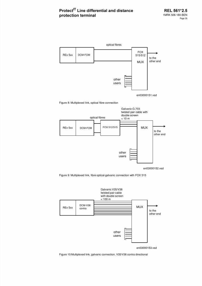
8/11/2019 1MRK506180-BEN a en Protect IT Line Differential and Distance Protection Terminal REL 561 2.5
http://slidepdf.com/reader/full/1mrk506180-ben-a-en-protect-it-line-differential-and-distance-protection-terminal 35/94
1MRK 506 180-BEN
Page 35
Figure 8: Multiplexed link, optical fibre connection
Figure 9: Multiplexed link, fibre optical-galvanic connection with FOX 515
Figure 10:Multiplexed link, galvanic connection, V35/V36 contra directional
REx 5xx DCM-FOMFOX
515/512
MUX
otherusers
to theother end
en03000151.vsd
optical fibres
otherusers
Galvanic G.703twisted pair cable withdouble screen< 10 m
to theother end
en03000152.vsd
REx 5xx DCM-FOM FOX 512/515 MUX
optical fibres
REx 5xxDCM-V36contra MUX
otherusers
to theother end
en03000153.vsd
Galvanic V35/V36twisted pair cablewith double screen
< 100 m
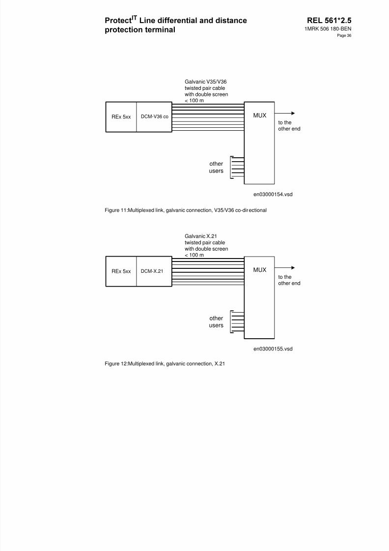
8/11/2019 1MRK506180-BEN a en Protect IT Line Differential and Distance Protection Terminal REL 561 2.5
http://slidepdf.com/reader/full/1mrk506180-ben-a-en-protect-it-line-differential-and-distance-protection-terminal 36/94
1MRK 506 180-BEN
Page 36
Figure 11:Multiplexed link, galvanic connection, V35/V36 co-directional
Figure 12:Multiplexed link, galvanic connection, X.21
REx 5xx DCM-V36 co MUX
otherusers
to theother end
en03000154.vsd
Galvanic V35/V36twisted pair cable
with double screen< 100 m
REx 5xx DCM-X.21 MUX
otherusers
to theother end
en03000155.vsd
Galvanic X.21twisted pair cablewith double screen< 100 m
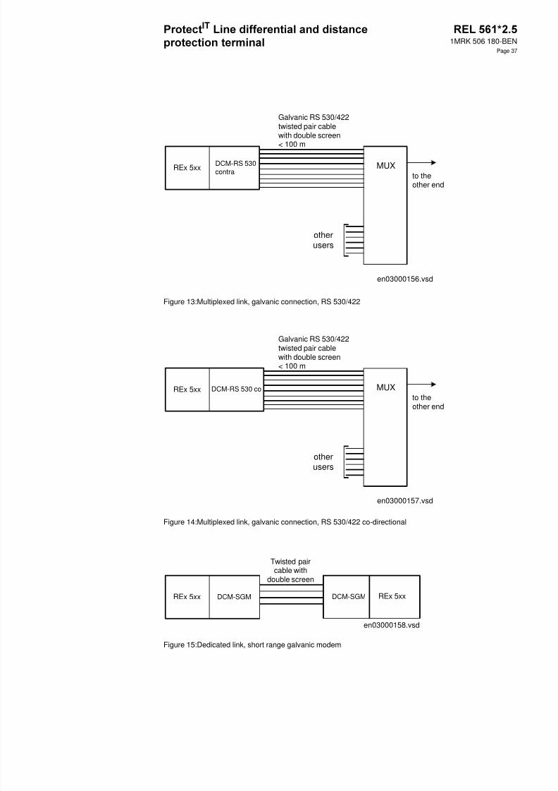
8/11/2019 1MRK506180-BEN a en Protect IT Line Differential and Distance Protection Terminal REL 561 2.5
http://slidepdf.com/reader/full/1mrk506180-ben-a-en-protect-it-line-differential-and-distance-protection-terminal 37/94
1MRK 506 180-BEN
Page 37
Figure 13:Multiplexed link, galvanic connection, RS 530/422
Figure 14:Multiplexed link, galvanic connection, RS 530/422 co-directional
Figure 15:Dedicated link, short range galvanic modem
REx 5xx DCM-RS 530contra
MUX
otherusers
to theother end
en03000156.vsd
Galvanic RS 530/422twisted pair cable
with double screen< 100 m
REx 5xx DCM-RS 530 co MUX
otherusers
to theother end
en03000157.vsd
Galvanic RS 530/422twisted pair cablewith double screen< 100 m
en03000158.vsd
REx 5xx
Twisted paircable with
double screen
REx 5xxDCM-SGMDCM-SGM

8/11/2019 1MRK506180-BEN a en Protect IT Line Differential and Distance Protection Terminal REL 561 2.5
http://slidepdf.com/reader/full/1mrk506180-ben-a-en-protect-it-line-differential-and-distance-protection-terminal 38/94
1MRK 506 180-BEN
Page 38
Figure 16:Multiplexed link, galvanic connection, G.703
Figure 17:Multiplexed link, optical fiber - galvanic connection V35/V36 with 21 - 15X
Galvanic G.703twisted pair cable with
double screen< 10 m
REx 5xx DCM-G.703MUX
otherusers
to theother end
en03000146.vsd
otherusers
Galvanic V35/V36twisted pair cable withdouble screen< 100 m
to theother end
en03000147.vsd
REx 5xx DCM-SFOM21-15XFIBERDATA
V35/V36
MUX
optical fibres
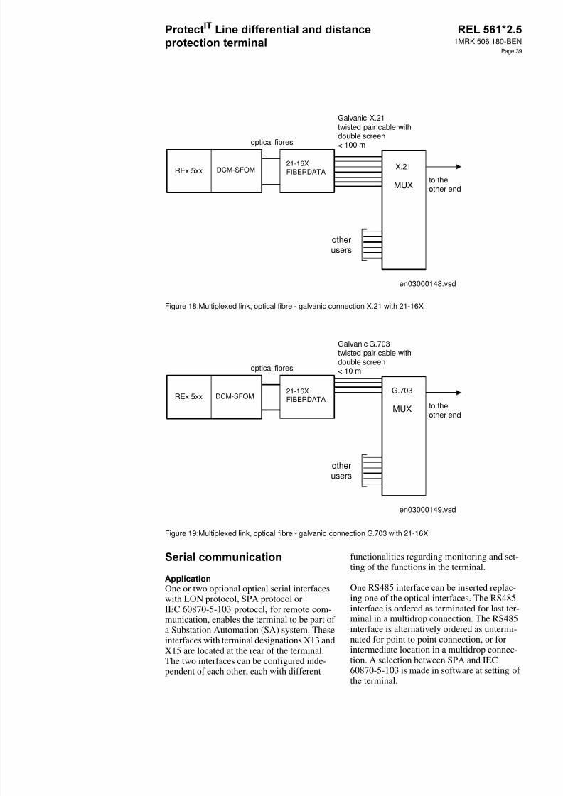
8/11/2019 1MRK506180-BEN a en Protect IT Line Differential and Distance Protection Terminal REL 561 2.5
http://slidepdf.com/reader/full/1mrk506180-ben-a-en-protect-it-line-differential-and-distance-protection-terminal 39/94
1MRK 506 180-BEN
Page 39
Figure 18:Multiplexed link, optical fibre - galvanic connection X.21 with 21-16X
Figure 19:Multiplexed link, optical fibre - galvanic connection G.703 with 21-16X
One or two optional optical serial interfaceswith LON protocol, SPA protocol orIEC 60870-5-103 protocol, for remote com-munication, enables the terminal to be part ofa Substation Automation (SA) system. Theseinterfaces with terminal designations X13 andX15 are located at the rear of the terminal.The two interfaces can be configured inde-pendent of each other, each with different
functionalities regarding monitoring and set-ting of the functions in the terminal.
One RS485 interface can be inserted replac-ing one of the optical interfaces. The RS485interface is ordered as terminated for last ter-minal in a multidrop connection. The RS485interface is alternatively ordered as untermi-nated for point to point connection, or forintermediate location in a multidrop connec-tion. A selection between SPA and IEC60870-5-103 is made in software at setting ofthe terminal.
otherusers
Galvanic X.21twisted pair cable with
double screen< 100 m
to theother end
en03000148.vsd
REx 5xx DCM-SFOM21-16XFIBERDATA
X.21
MUX
optical fibres
otherusers
Galvanic G.703twisted pair cable withdouble screen< 10 m
to the
other end
en03000149.vsd
REx 5xx DCM-SFOM21-16XFIBERDATA
G.703
MUX
optical fibres

8/11/2019 1MRK506180-BEN a en Protect IT Line Differential and Distance Protection Terminal REL 561 2.5
http://slidepdf.com/reader/full/1mrk506180-ben-a-en-protect-it-line-differential-and-distance-protection-terminal 40/94
1MRK 506 180-BEN
Page 40
This communication bus is mainly used forSMS. It can include different numericalrelays/terminals with remote communicationpossibilities. Connection to a personal com-puter (PC) can be made directly (if the PC islocated in the substation) or by telephone
modem through a telephone network withCCITT characteristics.
When communicating with a PC, using therear SPA port, the only hardware needed for astation monitoring system is:
• Optical fibres• Opto/electrical converter for the PC• PC
or
• A RS485 network installation accordingto EIA Standard RS485
• PC
Remote communication over the telephonenetwork also requires a telephone modem.
The software needed in the PC, either local orremote, is CAP 540.
SPA communication is applied when usingthe front communication port, but for this
purpose, no special serial communicationfunction is required in the terminal. Only thesoftware in the PC and a special cable forfront connection is needed.
This communication protocol is mainly usedwhen a protection terminal communicateswith a third party control system. This systemmust have a program that can interpret the
IEC 60870-5-103 communication messages.
As an alternative to the SPA communicationthe same port can be used for the IEC com-munication.
The IEC protocol may be used alternativelyon a fibre optic or on an RS485 network. Thefibre optic network is point to point only,while the RS485 network may be used by
multiple terminals in a multidrop configura-tion.
The IEC 60870-5-103 protocol implementa-tion in REx 5xx consists of these functions:
• Event handling• Report of analog service values (measure-
ments)• Fault location• Command handling
-Autorecloser ON/OFF
-Teleprotection ON/OFF-Protection ON/OFF-LED reset-Characteristics 1 - 4 (Setting groups)
• File transfer (disturbance files)• Time synchronization
The events created in the terminal availablefor the IEC protocol are based on the eventfunction blocks EV01 - EV06 and distur-bance function blocks DRP1 - DRP3. Thecommands are represented in a dedicatedfunction block ICOM. This block has outputsignals according to the IEC protocol for allcommands.
An optical network can be used within theSubstation Automation system. This enablescommunication with the terminal through theLON bus from the operator’s workplace,from the control center and also from otherterminals.
Alt 1 Alt 2 Alt 3
X13 SPA/IEC fibre optic SPA/IEC RS485 SPA fibre optic
X15 LON fibre optic LON fibre optic IEC fibre optic

8/11/2019 1MRK506180-BEN a en Protect IT Line Differential and Distance Protection Terminal REL 561 2.5
http://slidepdf.com/reader/full/1mrk506180-ben-a-en-protect-it-line-differential-and-distance-protection-terminal 41/94
1MRK 506 180-BEN
Page 41
An optical serial interface with LON protocolenables the terminal to be part of a SubstationControl System (SCS) and/or SubstationMonitoring System (SMS). This interface islocated at the rear of the terminal. The hard-ware needed for applying LON communica-tion depends on the application, but one verycentral unit needed is the LON Star Couplerand optic fibres connecting the star coupler tothe terminals. To communicate with the ter-minals from a Personal Computer (PC), theSMS 510, software or/and the applicationlibrary LIB 520 together with MicroSCADAis needed.
The serial communication module for SPA/ IEC is placed in a slot at the rear part of themain processing module. The serial commu-nication module can have connectors for:
• two plastic fibre cables; (Rx, Tx)• two glass fibre cables; (Rx, Tx)• galvanic RS485
The type of connection is chosen when order-ing the terminal.
The serial communication module for LON isplaced in a slot at the rear part of the Mainprocessing module. The serial communica-tion module can have connectors for:
• two plastic fibre cables; (Rx, Tx)• two glass fibre cables; (Rx, Tx)
The type of connection is chosen when order-ing the terminal.
The special front connection cable is used toconnect a PC COM-port to to the optical con-tact on the left side of the local HMI.
The cable includes an optical contact, anopto/electrical converter and an electricalcable with a standard 9-pole D-sub contact.This ensures a disturbance immune and safecommunication with the terminal.
xx01000039
Figure 20:Front connection cable
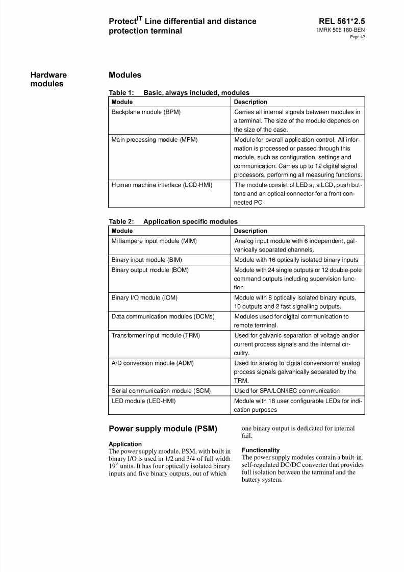
8/11/2019 1MRK506180-BEN a en Protect IT Line Differential and Distance Protection Terminal REL 561 2.5
http://slidepdf.com/reader/full/1mrk506180-ben-a-en-protect-it-line-differential-and-distance-protection-terminal 42/94
1MRK 506 180-BEN
Page 42
The power supply module, PSM, with built inbinary I/O is used in 1/2 and 3/4 of full width19” units. It has four optically isolated binaryinputs and five binary outputs, out of which
one binary output is dedicated for internalfail.
The power supply modules contain a built-in,self-regulated DC/DC converter that providesfull isolation between the terminal and thebattery system.
Backplane module (BPM) Carries all internal signals between modules ina terminal. The size of the module depends onthe size of the case.
Main processing module (MPM) Module for overall application control. All infor-mation is processed or passed through thismodule, such as configuration, settings andcommunication. Carries up to 12 digital signalprocessors, performing all measuring functions.
Human machine interface (LCD-HMI) The module consist of LED:s, a LCD, push but-tons and an optical connector for a front con-nected PC
Milliampere input module (MIM) Analog input module with 6 independent, gal-vanically separated channels.
Binary input module (BIM) Module with 16 optically isolated binary inputs
Binary output module (BOM) Module with 24 single outputs or 12 double-polecommand outputs including supervision func-tion
Binary I/O module (IOM) Module with 8 optically isolated binary inputs,10 outputs and 2 fast signalling outputs.
Data communication modules (DCMs) Modules used for digital communication toremote terminal.
Transformer input module (TRM) Used for galvanic separation of voltage and/orcurrent process signals and the internal cir-cuitry.
A/D conversion module (ADM) Used for analog to digital conversion of analogprocess signals galvanically separated by theTRM.
Serial communication module (SCM) Used for SPA/LON/IEC communication
LED module (LED-HMI) Module with 18 user configurable LEDs for indi-cation purposes
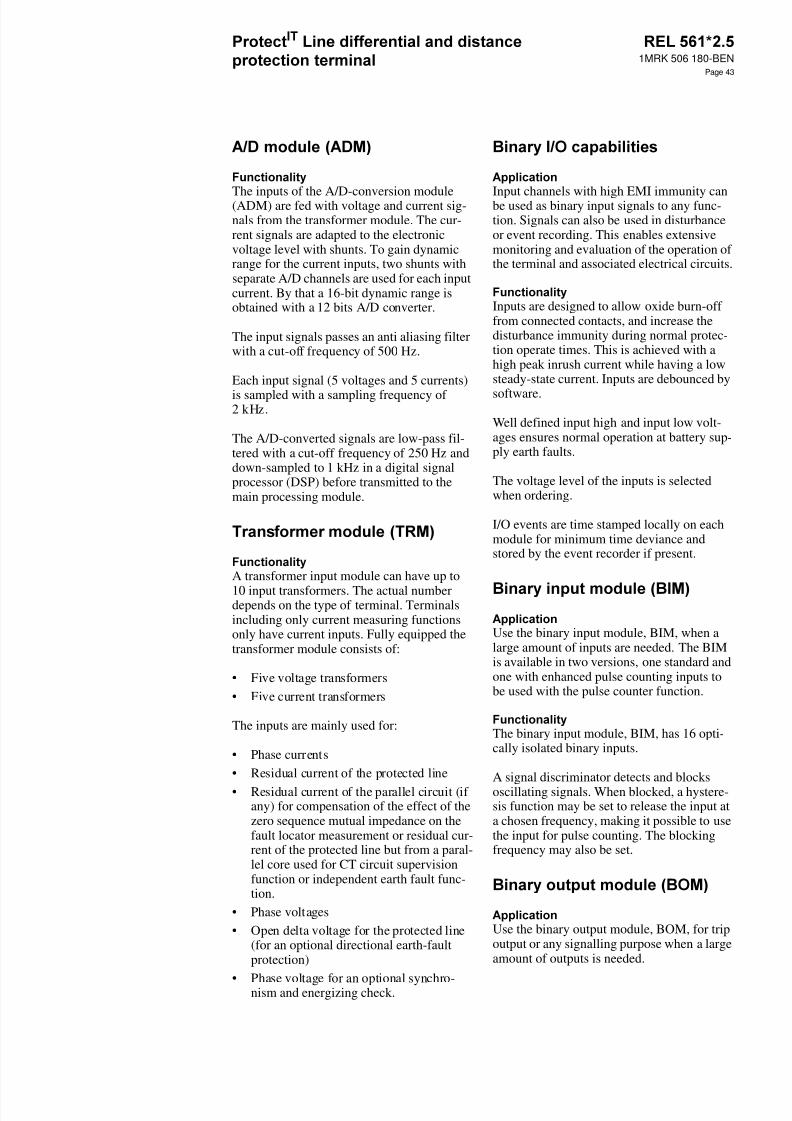
8/11/2019 1MRK506180-BEN a en Protect IT Line Differential and Distance Protection Terminal REL 561 2.5
http://slidepdf.com/reader/full/1mrk506180-ben-a-en-protect-it-line-differential-and-distance-protection-terminal 43/94
1MRK 506 180-BEN
Page 43
The inputs of the A/D-conversion module(ADM) are fed with voltage and current sig-nals from the transformer module. The cur-rent signals are adapted to the electronicvoltage level with shunts. To gain dynamicrange for the current inputs, two shunts withseparate A/D channels are used for each inputcurrent. By that a 16-bit dynamic range isobtained with a 12 bits A/D converter.
The input signals passes an anti aliasing filterwith a cut-off frequency of 500 Hz.
Each input signal (5 voltages and 5 currents)is sampled with a sampling frequency of2 kHz.
The A/D-converted signals are low-pass fil-tered with a cut-off frequency of 250 Hz anddown-sampled to 1 kHz in a digital signalprocessor (DSP) before transmitted to themain processing module.
A transformer input module can have up to10 input transformers. The actual numberdepends on the type of terminal. Terminalsincluding only current measuring functionsonly have current inputs. Fully equipped thetransformer module consists of:
• Five voltage transformers• Five current transformers
The inputs are mainly used for:
• Phase currents• Residual current of the protected line• Residual current of the parallel circuit (if
any) for compensation of the effect of thezero sequence mutual impedance on thefault locator measurement or residual cur-rent of the protected line but from a paral-lel core used for CT circuit supervisionfunction or independent earth fault func-tion.
• Phase voltages• Open delta voltage for the protected line
(for an optional directional earth-faultprotection)
• Phase voltage for an optional synchro-nism and energizing check.
Input channels with high EMI immunity canbe used as binary input signals to any func-tion. Signals can also be used in disturbanceor event recording. This enables extensivemonitoring and evaluation of the operation ofthe terminal and associated electrical circuits.
Inputs are designed to allow oxide burn-offfrom connected contacts, and increase thedisturbance immunity during normal protec-tion operate times. This is achieved with ahigh peak inrush current while having a lowsteady-state current. Inputs are debounced bysoftware.
Well defined input high and input low volt-ages ensures normal operation at battery sup-ply earth faults.
The voltage level of the inputs is selectedwhen ordering.
I/O events are time stamped locally on eachmodule for minimum time deviance andstored by the event recorder if present.
Use the binary input module, BIM, when alarge amount of inputs are needed. The BIMis available in two versions, one standard andone with enhanced pulse counting inputs tobe used with the pulse counter function.
The binary input module, BIM, has 16 opti-cally isolated binary inputs.
A signal discriminator detects and blocksoscillating signals. When blocked, a hystere-sis function may be set to release the input ata chosen frequency, making it possible to usethe input for pulse counting. The blockingfrequency may also be set.
Use the binary output module, BOM, for tripoutput or any signalling purpose when a largeamount of outputs is needed.
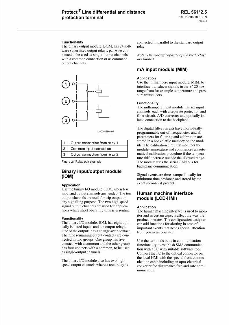
8/11/2019 1MRK506180-BEN a en Protect IT Line Differential and Distance Protection Terminal REL 561 2.5
http://slidepdf.com/reader/full/1mrk506180-ben-a-en-protect-it-line-differential-and-distance-protection-terminal 44/94
1MRK 506 180-BEN
Page 44
The binary output module, BOM, has 24 soft-ware supervised output relays, pairwise con-nected to be used as single-output channelswith a common connection or as commandoutput channels.
Figure 21:Relay pair example
Use the binary I/O module, IOM, when fewinput and output channels are needed. The tenoutput channels are used for trip output orany signalling purpose. The two high speedsignal output channels are used for applica-tions where short operating time is essential.
The binary I/O module, IOM, has eight opti-
cally isolated inputs and ten output relays.One of the outputs has a change-over contact.The nine remaining output contacts are con-nected in two groups. One group has fivecontacts with a common and the other grouphas four contacts with a common, to be usedas single-output channels.
The binary I/O module also has two highspeed output channels where a reed relay is
connected in parallel to the standard outputrelay.
Use the milliampere input module, MIM, tointerface transducer signals in the +/-20 mArange from for example temperature and pres-sure transducers.
The milliampere input module has six inputchannels, each with a separate protection andfilter circuit, A/D converter and optically iso-lated connection to the backplane.
The digital filter circuits have individuallyprogrammable cut-off frequencies, and allparameters for filtering and calibration arestored in a nonvolatile memory on the mod-ule. The calibration circuitry monitors themodule temperature and commences an auto-matical calibration procedure if the tempera-ture drift increase outside the allowed range.The module uses the serial CAN bus forbackplane communication.
Signal events are time stamped locally forminimum time deviance and stored by theevent recorder if present.
The human machine interface is used to mon-itor and in certain aspects affect the way theproduct operates. The configuration designercan add functions for alerting in case ofimportant events that needs special attentionfrom you as an operator.
Use the terminals built-in communicationfunctionality to establish SMS communica-tion with a PC with suitable software tool.Connect the PC to the optical connector onthe local HMI with the special front commu-nication cable including an opto-electricalconverter for disturbance free and safe com-munication.
1 Output connection from relay 1
2 Common input connection
3 Output connection from relay 2
xx00000299.vsd
5
5
2
1
3
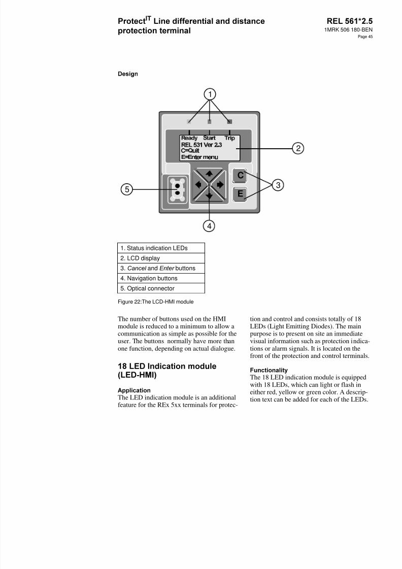
8/11/2019 1MRK506180-BEN a en Protect IT Line Differential and Distance Protection Terminal REL 561 2.5
http://slidepdf.com/reader/full/1mrk506180-ben-a-en-protect-it-line-differential-and-distance-protection-terminal 45/94
1MRK 506 180-BEN
Page 45
Figure 22:The LCD-HMI module
The number of buttons used on the HMImodule is reduced to a minimum to allow acommunication as simple as possible for theuser. The buttons normally have more thanone function, depending on actual dialogue.
The LED indication module is an additionalfeature for the REx 5xx terminals for protec-
tion and control and consists totally of 18LEDs (Light Emitting Diodes). The mainpurpose is to present on site an immediatevisual information such as protection indica-tions or alarm signals. It is located on thefront of the protection and control terminals.
The 18 LED indication module is equippedwith 18 LEDs, which can light or flash ineither red, yellow or green color. A descrip-tion text can be added for each of the LEDs.
1. Status indication LEDs
2. LCD display
3. and buttons
4. Navigation buttons
5. Optical connector
E
C
2
3
1
5
4
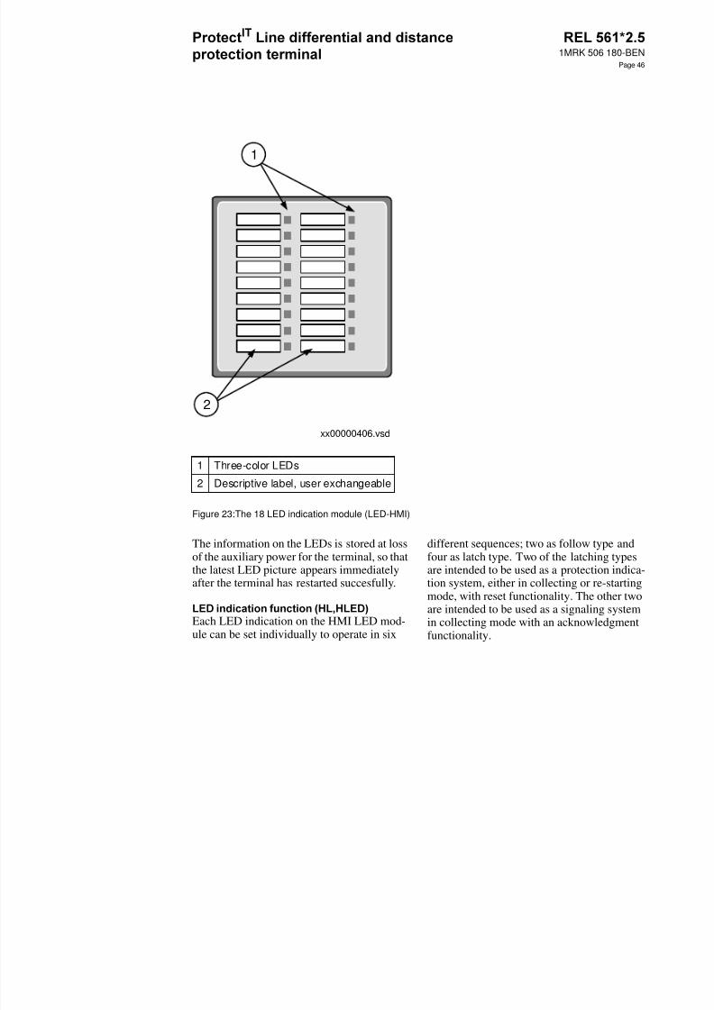
8/11/2019 1MRK506180-BEN a en Protect IT Line Differential and Distance Protection Terminal REL 561 2.5
http://slidepdf.com/reader/full/1mrk506180-ben-a-en-protect-it-line-differential-and-distance-protection-terminal 46/94
1MRK 506 180-BEN
Page 46
Figure 23:The 18 LED indication module (LED-HMI)
The information on the LEDs is stored at lossof the auxiliary power for the terminal, so thatthe latest LED picture appears immediatelyafter the terminal has restarted succesfully.
Each LED indication on the HMI LED mod-ule can be set individually to operate in six
different sequences; two as follow type andfour as latch type. Two of the latching typesare intended to be used as a protection indica-tion system, either in collecting or re-startingmode, with reset functionality. The other twoare intended to be used as a signaling systemin collecting mode with an acknowledgmentfunctionality.
1 Three-color LEDs
2 Descriptive label, user exchangeable
xx00000406.vsd
1
2
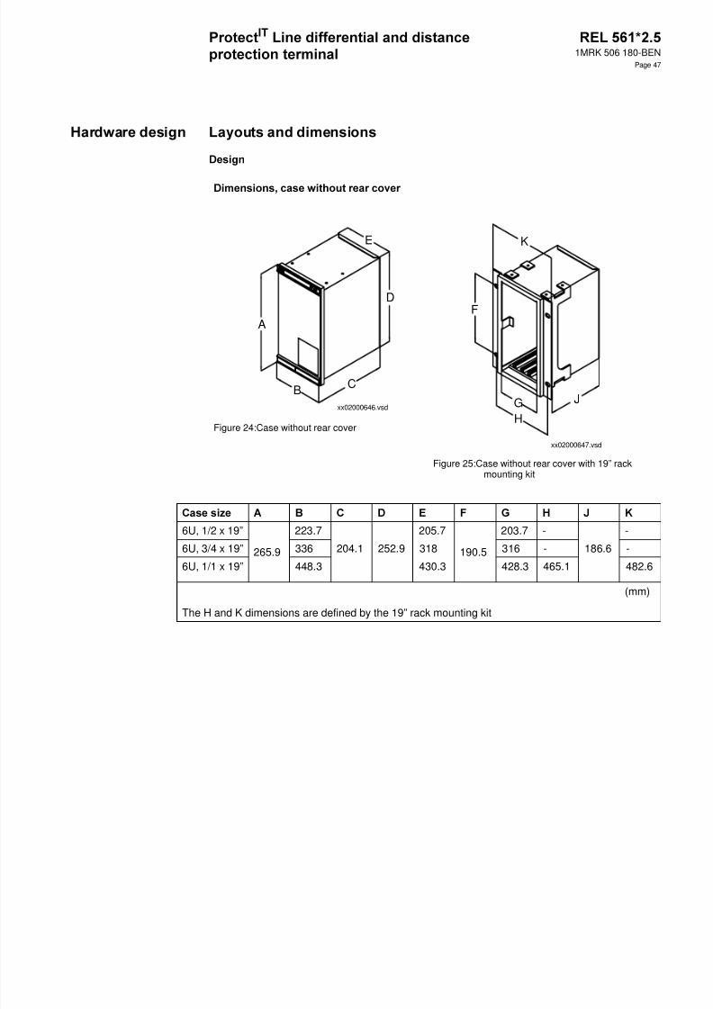
8/11/2019 1MRK506180-BEN a en Protect IT Line Differential and Distance Protection Terminal REL 561 2.5
http://slidepdf.com/reader/full/1mrk506180-ben-a-en-protect-it-line-differential-and-distance-protection-terminal 47/94
1MRK 506 180-BEN
Page 47
Figure 24:Case without rear cover
Figure 25:Case without rear cover with 19” rackmounting kit
A
B C
D
E
xx02000646.vsd
F
GH
J
K
xx02000647.vsd
6U, 1/2 x 19”
265.9
223.7 205.7
190.5
203.7 - -6U, 3/4 x 19” 336 204.1 252.9 318 316 - 186.6 -
6U, 1/1 x 19” 448.3 430.3 428.3 465.1 482.6
The H and K dimensions are defined by the 19” rack mounting kit
(mm)
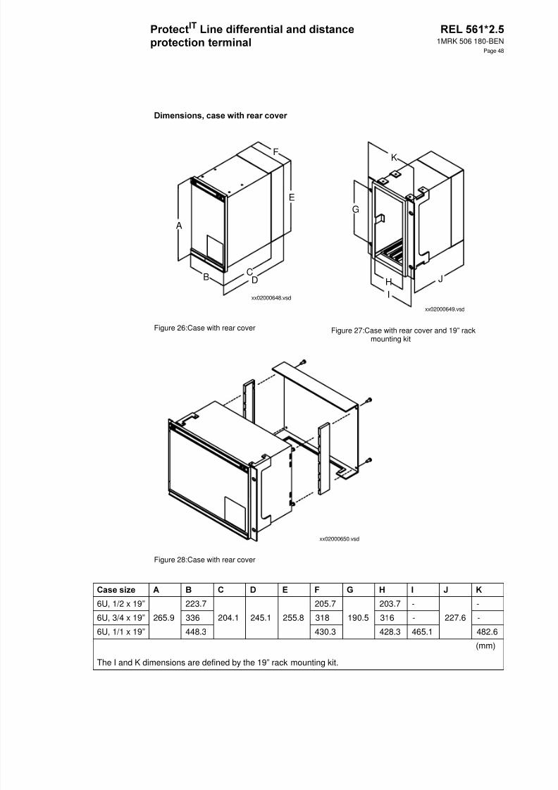
8/11/2019 1MRK506180-BEN a en Protect IT Line Differential and Distance Protection Terminal REL 561 2.5
http://slidepdf.com/reader/full/1mrk506180-ben-a-en-protect-it-line-differential-and-distance-protection-terminal 48/94
1MRK 506 180-BEN
Page 48
Figure 26:Case with rear cover Figure 27:Case with rear cover and 19” rackmounting kit
Figure 28:Case with rear cover
A
B CD
E
F
xx02000648.vsd
JIH
G
K
xx02000649.vsd
xx02000650.vsd
6U, 1/2 x 19” 223.7 205.7 203.7 - -
6U, 3/4 x 19” 265.9 336 204.1 245.1 255.8 318 190.5 316 - 227.6 -
6U, 1/1 x 19” 448.3 430.3 428.3 465.1 482.6
The I and K dimensions are defined by the 19” rack mounting kit.
(mm)

8/11/2019 1MRK506180-BEN a en Protect IT Line Differential and Distance Protection Terminal REL 561 2.5
http://slidepdf.com/reader/full/1mrk506180-ben-a-en-protect-it-line-differential-and-distance-protection-terminal 49/94

8/11/2019 1MRK506180-BEN a en Protect IT Line Differential and Distance Protection Terminal REL 561 2.5
http://slidepdf.com/reader/full/1mrk506180-ben-a-en-protect-it-line-differential-and-distance-protection-terminal 50/94
1MRK 506 180-BEN
Page 50
Figure 29:Flush mounting of side by side cases
6U, 3/4 x 19” 326.4 259.3 352.8 190.5 34.4 13.2 ø 6.4
6U, 1/1 x 19” 438.7 259.3 465.1 190.5 34.4 13.2 ø 6.4
(mm)
B
A
C
G
D
E
F
xx02000651.vsd
xx02000652.vsd
19"

8/11/2019 1MRK506180-BEN a en Protect IT Line Differential and Distance Protection Terminal REL 561 2.5
http://slidepdf.com/reader/full/1mrk506180-ben-a-en-protect-it-line-differential-and-distance-protection-terminal 51/94
1MRK 506 180-BEN
Page 51
Figure 30:Wall mounting
6U, 1/2 x 19” 292 267.1
6U, 3/4 x 19” 404.3 379.4 272.8 390 247
6U, 1/1 x 19” 516 491.1
80
xx02000653.vsd
E
A
B
CD
Screws M6 or
corresponding
en02000654.vsd

8/11/2019 1MRK506180-BEN a en Protect IT Line Differential and Distance Protection Terminal REL 561 2.5
http://slidepdf.com/reader/full/1mrk506180-ben-a-en-protect-it-line-differential-and-distance-protection-terminal 52/94
1MRK 506 180-BEN
Page 52
Figure 31:Hardware structure of the 3/4 of full width 19” case
en03000144.eps
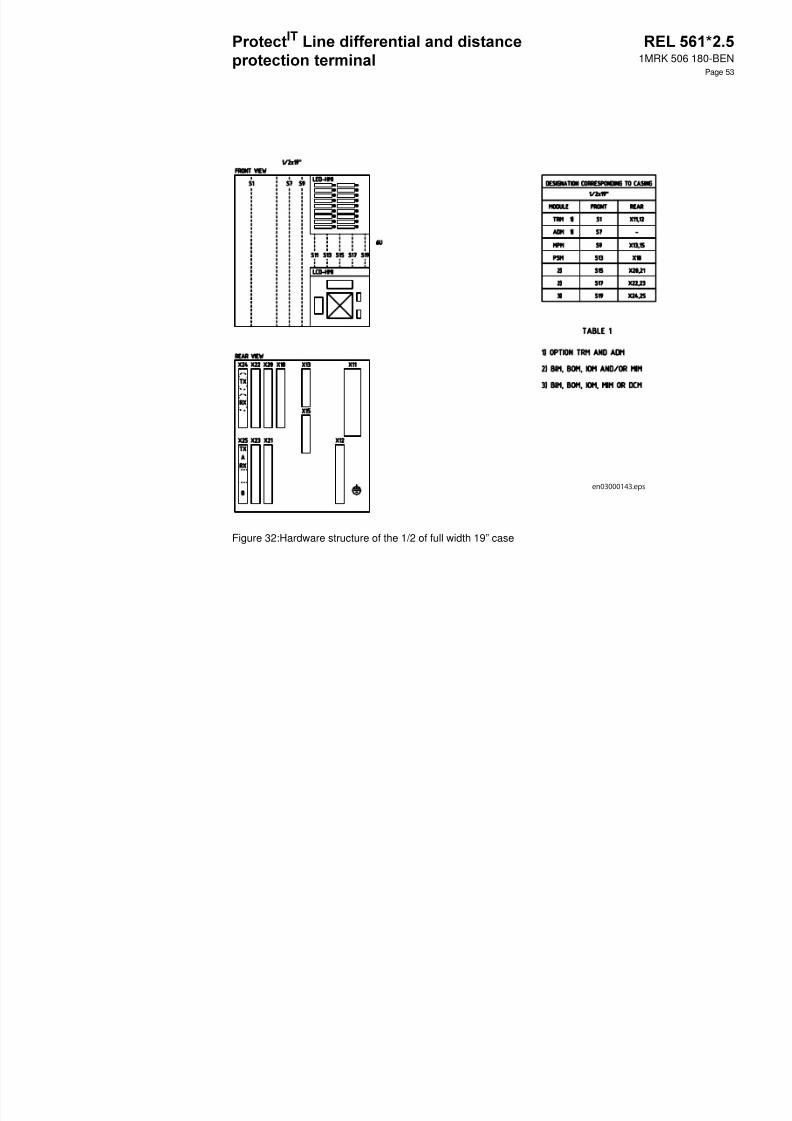
8/11/2019 1MRK506180-BEN a en Protect IT Line Differential and Distance Protection Terminal REL 561 2.5
http://slidepdf.com/reader/full/1mrk506180-ben-a-en-protect-it-line-differential-and-distance-protection-terminal 53/94
1MRK 506 180-BEN
Page 53
Figure 32:Hardware structure of the 1/2 of full width 19” case
en03000143.eps

8/11/2019 1MRK506180-BEN a en Protect IT Line Differential and Distance Protection Terminal REL 561 2.5
http://slidepdf.com/reader/full/1mrk506180-ben-a-en-protect-it-line-differential-and-distance-protection-terminal 54/94
1MRK 506 180-BEN
Page 54
xx00000440.vsd
X13:RXX13:TX
TX
HMIRXX15:TXX15:RX
HMI
LON OPTION
SPA / IEC-870-5-103OPTION
(MPM)
+
-
X18:17
18
1)
2)
3)
EL
L2
1
L1
L3
X11:
4
2
53
6
8
7
9
10
1
26
78
910
543
12
1416
18
X12:
5)
6)
4)
∩
(ADM)
INTERNALFAIL
(PSM)
INTERNALFAIL
X18:16
X18:15
+
12 22
14 24
11 21
13 23
5 0 1
501.24501.22
I1
I2
I3
I4
I5
U1
U2
U3
U4
U5
(TRM)
1) COMMUNICATION PORT SPA/IEC 870-5-1032) OPTICAL PORT ON LOCAL HMI.CONNECTION MADE WITH THE FRONTCONNECTION CABLE FOR PC.3) COMMUNICATION PORT LON4) RESERVED FOR PARALLEL LINECOMPENSATION OR CTSU ALT WEF 1 and 2WHEN Ir = 0,1A OR 0,5 A IS SELECTED ON TRM5) RESERVED FOR DIRECTIONAL EARTH-FAULT FUNCTION6) RESERVED FOR REF.VOLTAGE7) OPTIONAL ON/OFF SWITCH FOR THE DC-SUPPLY.
7)
The specified value of an influencing factor to which are referred the characteristics of the
equipment.
The range of values of an influencing quantity (factor) whithin which, under specified condi-tions, the equipment meets the specified requirements.
The range of values of a given energizing quantity for which the equipment, under specifiedconditions, is able to perform its intended functions according to the specified requirements.
Material Steel sheet
Front plate Steel sheet profile with cut-out for HMI and for 18 LED when included
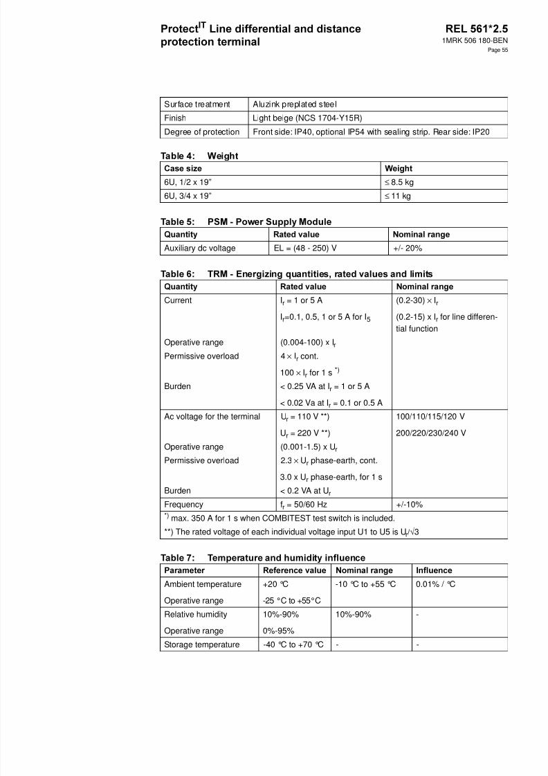
8/11/2019 1MRK506180-BEN a en Protect IT Line Differential and Distance Protection Terminal REL 561 2.5
http://slidepdf.com/reader/full/1mrk506180-ben-a-en-protect-it-line-differential-and-distance-protection-terminal 55/94
1MRK 506 180-BEN
Page 55
Surface treatment Aluzink preplated steel
Finish Light beige (NCS 1704-Y15R)
Degree of protection Front side: IP40, optional IP54 with sealing strip. Rear side: IP20
6U, 1/2 x 19” ≤ 8.5 kg
6U, 3/4 x 19” ≤ 11 kg
Auxiliary dc voltage EL = (48 - 250) V +/- 20%
Current I r = 1 or 5 A
Ir=0.1, 0.5, 1 or 5 A for I 5
(0.2-30) × Ir
(0.2-15) x I r for line differen-tial function
Operative range (0.004-100) x I r
Permissive overload 4 × Ir cont.
100 × Ir for 1 s *)
Burden < 0.25 VA at I r = 1 or 5 A
< 0.02 Va at Ir = 0.1 or 0.5 A
Ac voltage for the terminal U r = 110 V **)
Ur = 220 V **)
100/110/115/120 V
200/220/230/240 V
Operative range (0.001-1.5) x U r
Permissive overload 2.3 × Ur phase-earth, cont.
3.0 x U r phase-earth, for 1 s
Burden < 0.2 VA at U r
Frequency f r = 50/60 Hz +/-10%*) max. 350 A for 1 s when COMBITEST test switch is included.
**) The rated voltage of each individual voltage input U1 to U5 is U r/√3
Ambient temperature
Operative range
+20 °C
-25 °C to +55°C
-10 °C to +55 °C 0.01% / °C
Relative humidity
Operative range
10%-90%
0%-95%
10%-90% -
Storage temperature -40 °C to +70 °C - -
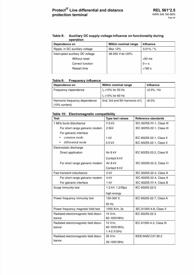
8/11/2019 1MRK506180-BEN a en Protect IT Line Differential and Distance Protection Terminal REL 561 2.5
http://slidepdf.com/reader/full/1mrk506180-ben-a-en-protect-it-line-differential-and-distance-protection-terminal 56/94
1MRK 506 180-BEN
Page 56
Ripple, in DC auxiliary voltage Max 12% 0.01% / %Interrupted auxiliary DC voltage 48-250 V dc ±20%
Without reset <50 ms
Correct function 0- ∞ s
Restart time <180 s
Frequency dependence f r ±10% for 50 Hz
fr ±10% for 60 Hz
±2.0% / Hz
Harmonic frequency dependence(10% content)
2nd, 3rd and 5th harmonic of f r ±6.0%
1 MHz burst disturbance 2.5 kV IEC 60255-22-1, Class III
For short range galvanic modem 2.5kV IEC 60255-22-1, Class III
For galvanic interface• common mode 1 kV IEC 60255-22-1, Class II• differential mode 0.5 kV IEC 60255-22-1, Class II
Electrostatic discharge
Direct application Air 8 kV
Contact 6 kV
IEC 60255-22-2, Class III
For short range galvanic modem Air 8 kV IEC 60255-22-2, Class III
Contact 6 kV
Fast transient disturbance 4 kV IEC 60255-22-4, Class A
For short range galvanic modem 4 kV IEC 60255-22-4, Class A
For galvanic interface 1 kV IEC 60255-22-4, Class B
Surge immunity test 1-2 kV, 1.2/50 µs
high energy
IEC 60255-22-5
Power frequency immunity test 150-300 V,
50 Hz
IEC 60255-22-7, Class A
Power frequency magnetic field test 1000 A/m, 3s IEC 61000-4-8, Class V
Radiated electromagnetic field distur-bance
10 V/m,80-1000 MHz
IEC 60255-22-3
Radiated electromagnetic field distur-bance
10 V/m,80-1000 MHz,1.4-2.0 GHz
IEC 61000-4-3, Class III
Radiated electromagnetic field distur-
bance
35 V/m
26-1000 MHz
IEEE/ANSI C37.90.2
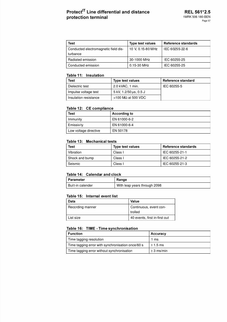
8/11/2019 1MRK506180-BEN a en Protect IT Line Differential and Distance Protection Terminal REL 561 2.5
http://slidepdf.com/reader/full/1mrk506180-ben-a-en-protect-it-line-differential-and-distance-protection-terminal 57/94
1MRK 506 180-BEN
Page 57
Conducted electromagnetic field dis-turbance
10 V, 0.15-80 MHz IEC 60255-22-6
Radiated emission 30-1000 MHz IEC 60255-25
Conducted emission 0.15-30 MHz IEC 60255-25
Dielectric test 2.0 kVAC, 1 min. IEC 60255-5
Impulse voltage test 5 kV, 1.2/50 µs, 0.5 J
Insulation resistance >100 M Ω at 500 VDC
Immunity EN 61000-6-2
Emissivity EN 61000-6-4
Low voltage directive EN 50178
Vibration Class I IEC 60255-21-1
Shock and bump Class I IEC 60255-21-2
Seismic Class I IEC 60255-21-3
Built-in calender With leap years through 2098
Recording manner Continuous, event con-trolled
List size 40 events, first in-first out
Time tagging resolution 1 ms
Time tagging error with synchronisation once/60 s ± 1.5 ms
Time tagging error without synchronisation ± 3 ms/min
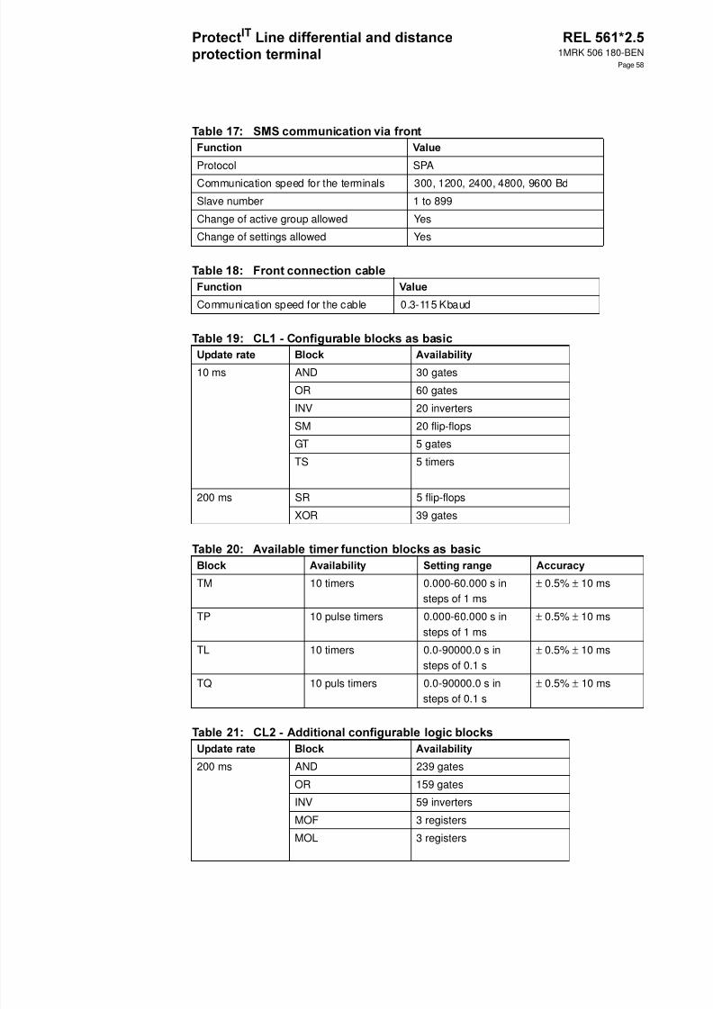
8/11/2019 1MRK506180-BEN a en Protect IT Line Differential and Distance Protection Terminal REL 561 2.5
http://slidepdf.com/reader/full/1mrk506180-ben-a-en-protect-it-line-differential-and-distance-protection-terminal 58/94
1MRK 506 180-BEN
Page 58
Protocol SPA
Communication speed for the terminals 300, 1200, 2400, 4800, 9600 Bd
Slave number 1 to 899
Change of active group allowed Yes
Change of settings allowed Yes
Communication speed for the cable 0.3-115 Kbaud
10 ms AND 30 gates
OR 60 gates
INV 20 inverters
SM 20 flip-flops
GT 5 gates
TS 5 timers
200 ms SR 5 flip-flops
XOR 39 gates
TM 10 timers 0.000-60.000 s insteps of 1 ms
± 0.5% ± 10 ms
TP 10 pulse timers 0.000-60.000 s insteps of 1 ms
± 0.5% ± 10 ms
TL 10 timers 0.0-90000.0 s insteps of 0.1 s
± 0.5% ± 10 ms
TQ 10 puls timers 0.0-90000.0 s insteps of 0.1 s
± 0.5% ± 10 ms
200 ms AND 239 gates
OR 159 gates
INV 59 inverters
MOF 3 registers
MOL 3 registers
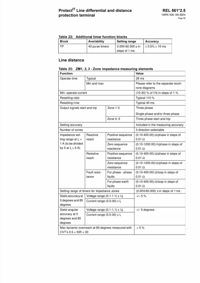
8/11/2019 1MRK506180-BEN a en Protect IT Line Differential and Distance Protection Terminal REL 561 2.5
http://slidepdf.com/reader/full/1mrk506180-ben-a-en-protect-it-line-differential-and-distance-protection-terminal 59/94
1MRK 506 180-BEN
Page 59
TP 40 pulse timers 0.000-60.000 s insteps of 1 ms
± 0.5% ± 10 ms
Operate time Typical 28 ms
Min and max Please refer to the separate isoch-rone diagrams
Min. operate current (10-30) % of I1b in steps of 1 %
Resetting ratio Typical 110 %Resetting time Typical 40 ms
Output signals start and trip Zone 1-3 Three phase
Single phase and/or three phase
Zone 4, 5 Three phase start and trip
Setting accuracy Included in the measuring accuracy
Number of zones 3 direction selectable
Impedance set-ting range at I r =1 A (to be divided
by 5 at I r = 5 A)
Reactivereach
Positive-sequencereactance
(0.10-400.00) Ω /phase in steps of0.01 Ω
Zero sequence
reactance
(0.10-1200.00) Ω /phase in steps of
0.01 ΩResistivereach
Positive-sequenceresistance
(0.10-400.00) Ω /phase in steps of0.01 Ω
Zero sequenceresistance
(0.10-1200.00) Ω /phase in steps of0.01 Ω
Fault resis-tance
For phase - phasefaults
(0.10-400.00) Ω /loop in steps of0.01 Ω
For phase-earthfaults
(0.10-400.00) Ω /loop in steps of0.01 Ω
Setting range of timers for impedance zones (0.000-60.000) s in steps of 1 ms
Static accuracy at0 degrees and 85degrees
Voltage range (0.1-1.1) x U r +/- 5 %
Current range (0.5-30) x I r
Static angularaccuracy at 0degrees and 85degrees
Voltage range (0.1-1,1) x U r +/- 5 degrees
Current range (0.5-30) x I r
Max dynamic overreach at 85 degrees measured withCVT’s 0.5 < SIR < 30
+ 5 %

8/11/2019 1MRK506180-BEN a en Protect IT Line Differential and Distance Protection Terminal REL 561 2.5
http://slidepdf.com/reader/full/1mrk506180-ben-a-en-protect-it-line-differential-and-distance-protection-terminal 60/94
1MRK 506 180-BEN
Page 60
Impedance set-ting rangeat Ir=1 A
Reactive reach Positive sequencereactance
0.10-400.00 ohm/phase insteps of 0.01 ohm/phase
Zero sequencereactance
0.10-1200.00 ohm/phase insteps of 0.01 ohm/phase
Resistive reach For phase to phasefaults
0.10-400.00 ohm/loop in stepsof 0.01 ohm/loop
For phase toground faults
0.10-400.00 ohm/loop in stepsof 0.01 ohm/loop
Static accuracy at
0 degrees and 85degrees
Voltage range (0.1-1.1) x U r ± 5 %
Current range (0.5-30) x I r
Static angularaccuracy at 0degrees and 85degrees
Voltage range (0.1-1.1) x U r +/-5 degreesCurrent range (0.2-30) x I r
Impedance setting rangeat I r =1A
(divide values by 5 for I r =5A)
Reactive reach,XIN
0.10-400.00 ohm/ phase in steps of 0.01ohm/phase
Resistive reach,RIN
0.10-400.00 ohm/ phase in stepsof 0.01ohm/phase
Reach multiplication factor, KX 120-200% of XIN insteps of 1%
Reach multiplication factor, KR 120-200% of RIN insteps of 1%
Initial PSD timer, tP1 0.000-60.000 s insteps of 1 ms
+/- 0.5 % +/- 10 ms
Fast PSD timer, tP2 0.000-60.000 s insteps of 1 ms
+/- 0.5 % +/- 10 ms
Hold timer tW for activation of fast PSD timer 0.000-60.000 s insteps of 1 ms
+/- 0.5 % +/- 10 ms
Hold timer tH for PSD detected 0.000-60.000 s insteps of 1 ms
+/- 0.5 % +/- 10 ms
Timer tEF overcoming 1ph reclosing deadtime
0.000-60.000 s insteps of 1 ms
+/- 0.5 % +/- 10 ms
Timer tR1 to time delay block by the residualcurrent
0.000-60.000 s insteps of 1 ms
+/- 0.5 % +/- 10 ms
Timer tR2 to time delay block at very slowswings
0.000-60.000 s insteps of 1 ms
+/- 0.5 % +/- 10 ms
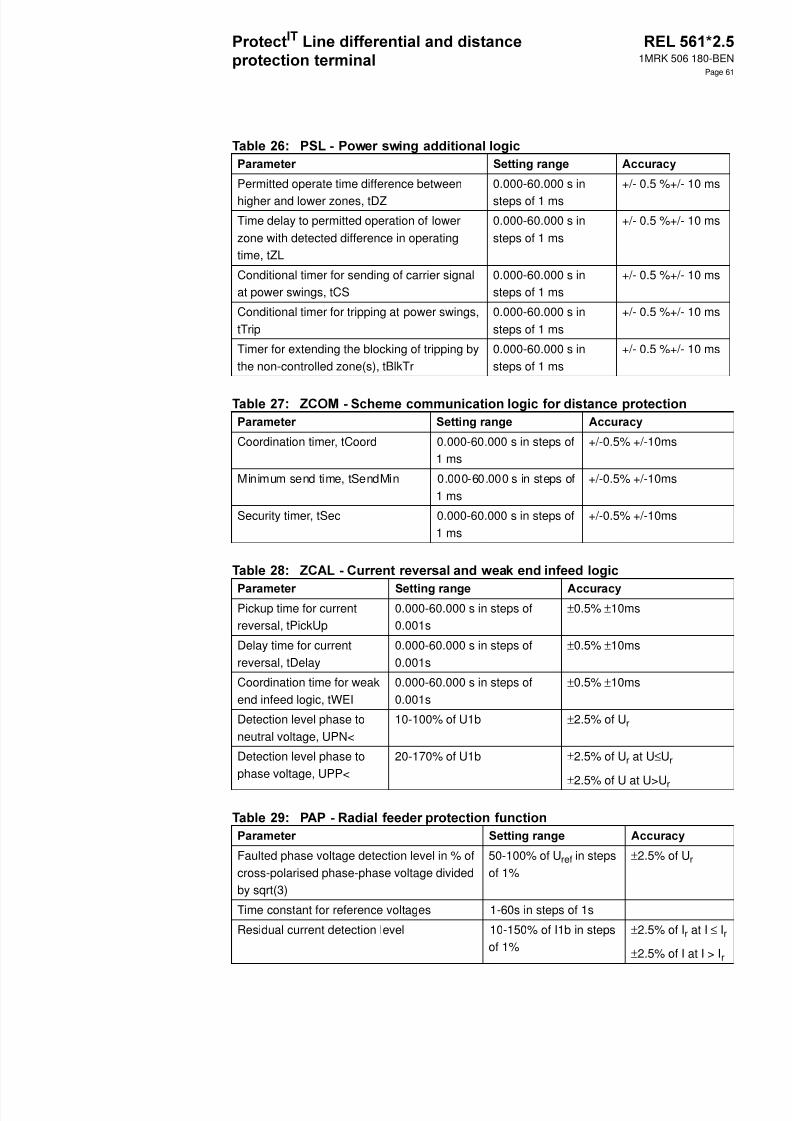
8/11/2019 1MRK506180-BEN a en Protect IT Line Differential and Distance Protection Terminal REL 561 2.5
http://slidepdf.com/reader/full/1mrk506180-ben-a-en-protect-it-line-differential-and-distance-protection-terminal 61/94
1MRK 506 180-BEN
Page 61
Permitted operate time difference betweenhigher and lower zones, tDZ
0.000-60.000 s insteps of 1 ms
+/- 0.5 %+/- 10 ms
Time delay to permitted operation of lowerzone with detected difference in operatingtime, tZL
0.000-60.000 s insteps of 1 ms
+/- 0.5 %+/- 10 ms
Conditional timer for sending of carrier signalat power swings, tCS
0.000-60.000 s insteps of 1 ms
+/- 0.5 %+/- 10 ms
Conditional timer for tripping at power swings,tTrip
0.000-60.000 s insteps of 1 ms
+/- 0.5 %+/- 10 ms
Timer for extending the blocking of tripping bythe non-controlled zone(s), tBlkTr
0.000-60.000 s insteps of 1 ms
+/- 0.5 %+/- 10 ms
Coordination timer, tCoord 0.000-60.000 s in steps of1 ms
+/-0.5% +/-10ms
Minimum send time, tSendMin 0.000-60.000 s in steps of1 ms
+/-0.5% +/-10ms
Security timer, tSec 0.000-60.000 s in steps of1 ms
+/-0.5% +/-10ms
Pickup time for currentreversal, tPickUp
0.000-60.000 s in steps of0.001s
±0.5% ±10ms
Delay time for currentreversal, tDelay
0.000-60.000 s in steps of0.001s
±0.5% ±10ms
Coordination time for weakend infeed logic, tWEI
0.000-60.000 s in steps of0.001s
±0.5% ±10ms
Detection level phase toneutral voltage, UPN<
10-100% of U1b ±2.5% of U r
Detection level phase tophase voltage, UPP<
20-170% of U1b ±2.5% of U r at U ≤Ur
±2.5% of U at U>U r
Faulted phase voltage detection level in % ofcross-polarised phase-phase voltage dividedby sqrt(3)
50-100% of U ref in stepsof 1%
±2.5% of U r
Time constant for reference voltages 1-60s in steps of 1s
Residual current detection level 10-150% of I1b in stepsof 1%
±2.5% of I r at I ≤ Ir
±2.5% of I at I > I r
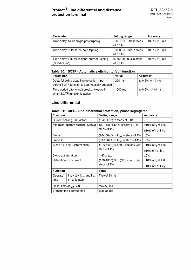
8/11/2019 1MRK506180-BEN a en Protect IT Line Differential and Distance Protection Terminal REL 561 2.5
http://slidepdf.com/reader/full/1mrk506180-ben-a-en-protect-it-line-differential-and-distance-protection-terminal 62/94

8/11/2019 1MRK506180-BEN a en Protect IT Line Differential and Distance Protection Terminal REL 561 2.5
http://slidepdf.com/reader/full/1mrk506180-ben-a-en-protect-it-line-differential-and-distance-protection-terminal 63/94
1MRK 506 180-BEN
Page 63
Compensated minimumoperate current, IMinOp-Comp
(20-150) % of I1b in steps of 1% ±10% of I r at I≤Ir
±10% of I at I>I r
Positive-sequence linecapacitive reactance XC1
Ir=1A: (60-6000) ohm/phase in steps of1ohm
Ir=5A: (12-1200) ohm/phase in steps of1ohm
-
Zero-sequence line capaci-tive reactance XC0
Ir=1A: (60-6000) ohm/phase in steps of1ohm
Ir=5A: (12-1200) ohm/phase in steps of1ohm
-
Operate cur-rent I>>
Phase measur-ing elements
(50-2000)% ofI1b In steps of1%
- ± 2.5 % of I r at I ≤Ir
± 2.5 % of I at I > I r
-Residual measur-ing elements
(50-2000)% ofI1b In steps of
1%
± 2.5 % of I r at I ≤ Ir
± 2.5 % of I at I > I r
Maximum operate time at I > 10 × Iset Max. 15ms -
Dynamic overreach at τ< 100 ms - < 5%
Operate current Phase measuring ele-ments, IP>
(10-400) % of I1bin steps of 1 %
± 2.5 % of I r at I ≤ Ir± 2.5 % of I at I >I r
Residual measuringelements, IN>
(10-150) % of I4bin steps of 1 %
± 2.5 % of I r at I ≤ Ir± 2.5 % of I at I >I r
Time delay Phase measuring ele-ments
(0.000-60.000) s insteps of 1 ms ± 0.5 % of t ± 10 ms
Residual measuringelements
(0.000-60.000) s insteps of 1 ms
± 0.5 % of t ± 10 ms
Dynamic overreach at τ< 100 ms - < 5 %
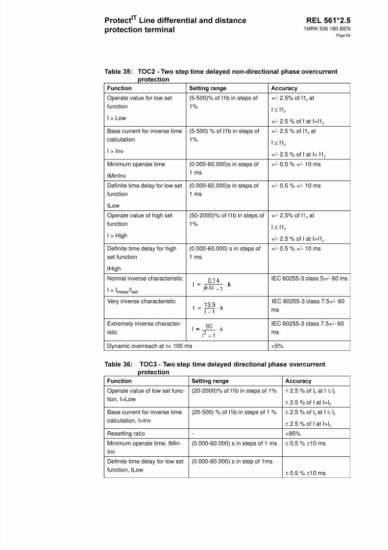
8/11/2019 1MRK506180-BEN a en Protect IT Line Differential and Distance Protection Terminal REL 561 2.5
http://slidepdf.com/reader/full/1mrk506180-ben-a-en-protect-it-line-differential-and-distance-protection-terminal 64/94
1MRK 506 180-BEN
Page 64
Operate value for low setfunction
I > Low
(5-500)% of I1b in steps of1%
+/- 2.5% of I1 r at
I ≤ I1r
+/- 2.5 % of I at I>I1 r
Base current for inverse timecalculation
I > Inv
(5-500) % of I1b in steps of1%
+/- 2.5 % of I1 r at
I ≤ I1r
+/- 2.5 % of I at I> I1 r
Minimum operate time
tMinInv
(0.000-60.000)s in steps of1 ms
+/- 0.5 % +/- 10 ms
Definite time delay for low set
function
tLow
(0.000-60.000)s in steps of
1 ms
+/- 0.5 % +/- 10 ms
Operate value of high setfunction
I > High
(50-2000)% of I1b in steps of1%
+/- 2.5% of I1 r at
I ≤ I1r
+/- 2.5 % of I at I>I1 r
Definite time delay for highset function
tHigh
(0.000-60.000) s in steps of1 ms
+/- 0.5 % +/- 10 ms
Normal inverse characteristic
I = Imeas /Iset
IEC 60255-3 class 5+/- 60 ms
Very inverse characteristic IEC 60255-3 class 7.5+/- 60ms
Extremely inverse character-istic
IEC 60255-3 class 7.5+/- 60ms
Dynamic overreach at τ< 100 ms <5%
Operate value of low set func-tion, I>Low
(20-2000)% of I1b in steps of 1% ± 2.5 % of I r at I ≤ Ir
± 2.5 % of I at I>I r
Base current for inverse timecalculation, I>Inv
(20-500) % of I1b in steps of 1 % ± 2.5 % of I r at I ≤ Ir
± 2.5 % of I at I>I r
Resetting ratio - >95%
Minimum operate time, tMin-Inv
(0.000-60.000) s in steps of 1 ms ± 0.5 % ±10 ms
Definite time delay for low setfunction, tLow
(0.000-60.000) s in step of 1ms
± 0.5 % ±10 ms
t 13.5I 1–----------- k⋅=
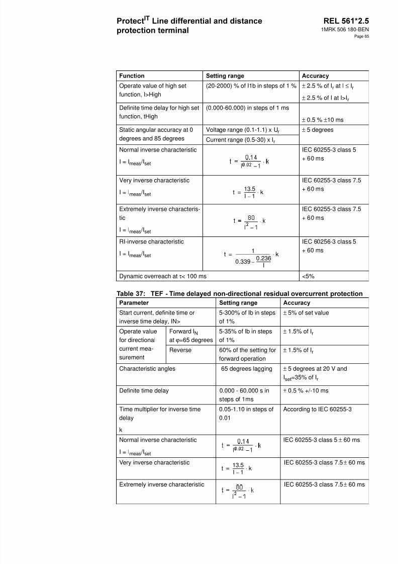
8/11/2019 1MRK506180-BEN a en Protect IT Line Differential and Distance Protection Terminal REL 561 2.5
http://slidepdf.com/reader/full/1mrk506180-ben-a-en-protect-it-line-differential-and-distance-protection-terminal 65/94
1MRK 506 180-BEN
Page 65
Operate value of high setfunction, I>High
(20-2000) % of I1b in steps of 1 % ± 2.5 % of I r at I ≤ Ir
± 2.5 % of I at I>I rDefinite time delay for high setfunction, tHigh
(0.000-60.000) in steps of 1 ms
± 0.5 % ±10 ms
Static angular accuracy at 0degrees and 85 degrees
Voltage range (0.1-1.1) x U r ± 5 degrees
Current range (0.5-30) x I r
Normal inverse characteristic
I = Imeas /Iset
IEC 60255-3 class 5+ 60 ms
Very inverse characteristic
I = Imeas /Iset
IEC 60255-3 class 7.5+ 60 ms
Extremely inverse characteris-tic
I = Imeas /Iset
IEC 60255-3 class 7.5+ 60 ms
RI-inverse characteristic
I = Imeas /Iset
IEC 60256-3 class 5+ 60 ms
Dynamic overreach at τ< 100 ms <5%
Start current, definite time orinverse time delay, IN>
5-300% of Ib in stepsof 1%
± 5% of set value
Operate valuefor directionalcurrent mea-surement
Forward I N at ϕ=65 degrees
5-35% of Ib in stepsof 1%
± 1.5% of I r
Reverse 60% of the setting forforward operation
± 1.5% of I r
Characteristic angles 65 degrees lagging ± 5 degrees at 20 V andIset =35% of I r
Definite time delay 0.000 - 60.000 s insteps of 1ms
± 0.5 % +/-10 ms
Time multiplier for inverse timedelay
k
0.05-1.10 in steps of0.01
According to IEC 60255-3
Normal inverse characteristic
I = Imeas /Iset
IEC 60255-3 class 5 ± 60 ms
Very inverse characteristic IEC 60255-3 class 7.5 ± 60 ms
Extremely inverse characteristic IEC 60255-3 class 7.5 ± 60 ms
t 13.5
I 1–----------- k⋅=
t 1
0.339 0.236I
-------------- -–------------------------------------ k⋅=
t 13.5I 1–----------- k⋅=

8/11/2019 1MRK506180-BEN a en Protect IT Line Differential and Distance Protection Terminal REL 561 2.5
http://slidepdf.com/reader/full/1mrk506180-ben-a-en-protect-it-line-differential-and-distance-protection-terminal 66/94
1MRK 506 180-BEN
Page 66
Logarithmic characteristic ± 5 % of t at I = (1.3-29) × IN
Min. operate current for depen-dent characteristic, IMin
100-400% of IN insteps of 1%
± 5% of I set
Minimum operate time for depen-dent characteristic, tMin
0.000-60.000 s insteps of 1 ms
± 0.5 % ± 10 ms
Minimum polarising voltage 1 % of U r At 50 Hz: 1% of U r ± 5%
At 60 Hz: 1% of U r -15% to -5%
Reset time <70 ms -
Current level for step 1, IN1> 50 - 2500% of Ib insteps of 1%
± 5 % of I r at I ≤Ir
± 5% of I at I>I r
Definite time delay for step 1, t1 0.000 - 60.000 s insteps of 1ms
± 0.5 % ±10 ms
Current level for step 2, IN2> 20 - 1500 % of Ib insteps of 1%
± 5 % of I r at I ≤Ir
± 5% of I at I>I r
Definite time delay for step 2, t2 0.000 - 60.000 s insteps of 1 ms
± 0.5 % ± 10 ms
Current level for step 3, IN3> 20 - 1500 % of Ib insteps of 1%
± 5 % of I r at I ≤Ir
± 5% of I at I>I r
Definite time delay for step 3, t3 0.000 - 60.000 s insteps of 1 ms
+/- 0.5 % ± 10 ms
Current level for step 4 definite timedelay or minimum operate current forinverse time delay, IN4>
4 - 440 % of Ib in stepsof 0.1%
± 5 % of I r at I ≤Ir
± 5% of I at I>I r
Definite time delay for step 4 or inversetime additional delay, t4
0.000 - 60.000 s insteps of 1 ms
± 0.5 % ±10 ms
Base current for inverse t ime delay,
IN>Inv
4 - 110% of Ib in steps
of 0.1%
± 5 % of I r at I ≤Ir
± 5% of I at I>I r
Time multiplier for inverse time delay 0.05 - 1.10 in steps of0.01
-
Inverse time minimum delay step 4 0.000 - 60.000 s insteps of 1 ms
± 0.5 % ± 10 ms
Operate value fordirectional currentmeasurement
Forward I N at ϕ=65°
5-40% of Ib in steps of1%
± 2.5 % of I r at I≤Ir
± 2.5% of I at I>I r
Reverse 60% of Forward ± 2.5 % of I r at I≤Ir
± 2.5% of I at I>I r
Level of harmonic restrain 20% or 32% ± 5%
t 5.8 1.35– lnI
IN-----⋅=

8/11/2019 1MRK506180-BEN a en Protect IT Line Differential and Distance Protection Terminal REL 561 2.5
http://slidepdf.com/reader/full/1mrk506180-ben-a-en-protect-it-line-differential-and-distance-protection-terminal 67/94
1MRK 506 180-BEN
Page 67
Characteristic angle
I = Imeas /Iset
65° lagging ± 5°at 20 V and I set =35 % of I
rNormal inverse characteristic
I = Imeas /Iset
IEC 60255-3 class 5± 60 ms
Very inverse characteristic IEC 60255-3 class 7.5± 60 ms
Extremely inverse characteristic IEC 60255-3 class 7.5± 60 ms
Logarithmic characteristic ± 5 % of t at I = (1.3-29)× IN
Switch onto fault active time, t4U 0.000 - 60.000 s insteps of 1 ms
± 0.5 % ± 10 ms
Operate current, IN> (3.0 - 2000.0 ) % of Ib insteps of 0.1%
± 2.5% of I r at I ≤ Ir
± 2.5% of I at I > Ir
Operate voltage, UN> (5.0 - 70.0) % of Ub in stepsof 0.1%
± 2.5% of U r at U ≤ Ur
± 2.5% of U at U > Ur
Characteristic Angle (-90.0 to +90.0) degrees in
steps of 0.1 degreesDefinite time delay, tTrip (0.000 - 60.000) s in steps of
1 ms± 0.5% ± 10 ms
Reset ratio > 90% typically
Operate current, IN> (5.0 - 400.0) % of I b in stepsof 0.1%
± 2.5% of I r at I ≤ Ir
± 2.5% of I at I > Ir
Operate voltage, UN> (1.0-70.0) % of U b in steps of
0.1%
± 2.5% of U r at U ≤ Ur
± 2.5% of U at U > Ur
Characteristic angle (-90.0 to +90.0) degrees insteps of 0.1 degrees
Definite time delay, tTrip (0.000-60.000) s in steps of 1ms
± 0.5% ± 10 ms
Inverse characteristic k = (0.0-2.0) in steps of 0.01
Sref = (5.0 - 50.0) % of Sb insteps of 0.1%
IEC 60255-3 class 5 ± 60 ms
Reset ratio > 90% typically
t 13.5I 1–----------- k⋅=
t 5.8 1.35– ln IIN-----⋅=
T i S measured=
S refk

8/11/2019 1MRK506180-BEN a en Protect IT Line Differential and Distance Protection Terminal REL 561 2.5
http://slidepdf.com/reader/full/1mrk506180-ben-a-en-protect-it-line-differential-and-distance-protection-terminal 68/94
1MRK 506 180-BEN
Page 68
Coordination timer 0.000-60.000 s in steps of 1ms
± 0.5% ± 10 ms
Operate voltage for WEI trip, U> 5-70 % of U1b in steps of 1% ± 5% of set value
Current reversal pickup timer,tPickUp
0.000-60.000 s in steps of 1 ms ± 0.5% ± 10 ms
Current reversal delay timer, tDelay 0.000-60.000 s in steps of 1 ms ± 0.5% ± 10 ms
Mode of operation Off / NonComp / Comp
( Function blocked/No temp.compensation/Temp. comp.)
Base current
IBase (10 - 200 ) % of I1b in stepsof 1 %
± 2.5% of I r
Temperature rise at IBase
TBase (0 - 100) °C in steps of 1° C ± 1°CTime constant
tau (1 - 62) min in steps of 1 min ± 1 min
Alarm temperature
TAlarm (50 - 150) °C in steps of 1°C
Trip temperature
TTrip (50 - 150) °C in steps of 1 °C
Temp. difference for reset oftrip
TdReset(5 - 30) °C in steps of 1°C
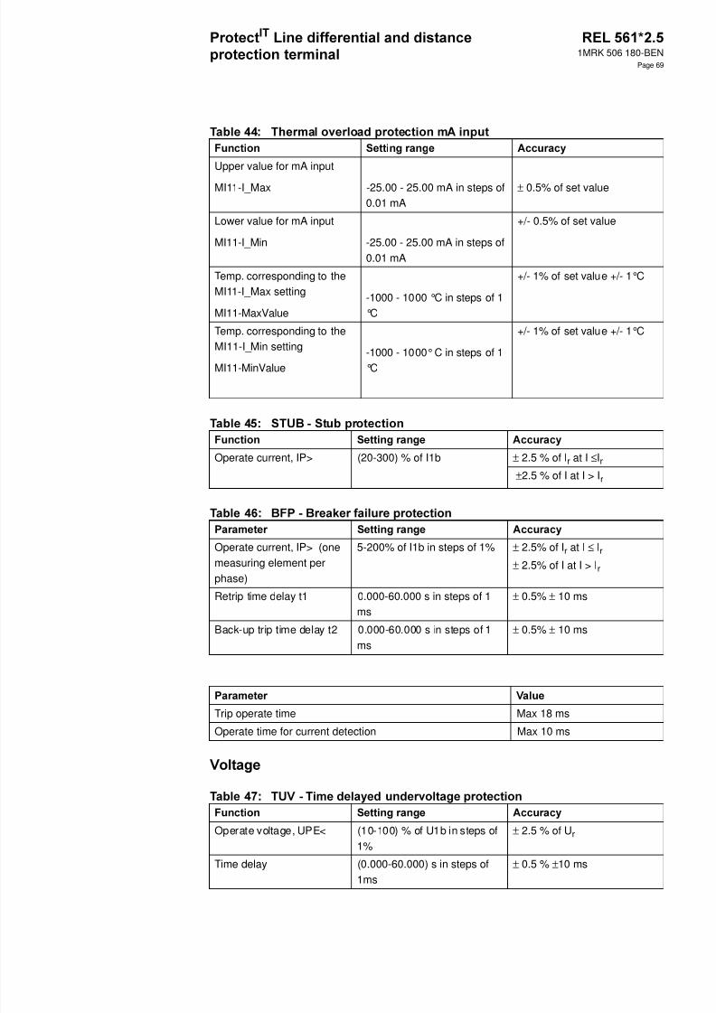
8/11/2019 1MRK506180-BEN a en Protect IT Line Differential and Distance Protection Terminal REL 561 2.5
http://slidepdf.com/reader/full/1mrk506180-ben-a-en-protect-it-line-differential-and-distance-protection-terminal 69/94
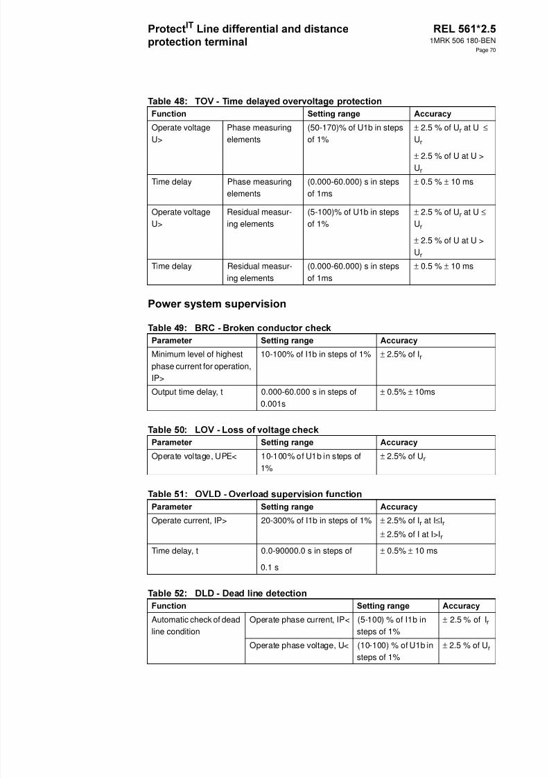
8/11/2019 1MRK506180-BEN a en Protect IT Line Differential and Distance Protection Terminal REL 561 2.5
http://slidepdf.com/reader/full/1mrk506180-ben-a-en-protect-it-line-differential-and-distance-protection-terminal 70/94
1MRK 506 180-BEN
Page 70
Operate voltageU>
Phase measuringelements
(50-170)% of U1b in stepsof 1%
± 2.5 % of U r at U ≤ Ur
± 2.5 % of U at U > Ur
Time delay Phase measuringelements
(0.000-60.000) s in stepsof 1ms
± 0.5 % ± 10 ms
Operate voltageU>
Residual measur-ing elements
(5-100)% of U1b in stepsof 1%
± 2.5 % of U r at U ≤Ur
± 2.5 % of U at U >Ur
Time delay Residual measur-ing elements
(0.000-60.000) s in stepsof 1ms
± 0.5 % ± 10 ms
Minimum level of highestphase current for operation,IP>
10-100% of I1b in steps of 1% ± 2.5% of I r
Output time delay, t 0.000-60.000 s in steps of0.001s
± 0.5% ± 10ms
Operate voltage, UPE< 10-100% of U1b in steps of1%
± 2.5% of U r
Operate current, IP> 20-300% of I1b in steps of 1% ± 2.5% of I r at I ≤Ir± 2.5% of I at I>I r
Time delay, t 0.0-90000.0 s in steps of
0.1 s
± 0.5% ± 10 ms
Automatic check of deadline condition
Operate phase current, IP< (5-100) % of I1b insteps of 1%
± 2.5 % of I r
Operate phase voltage, U< (10-100) % of U1b insteps of 1%
± 2.5 % of U r
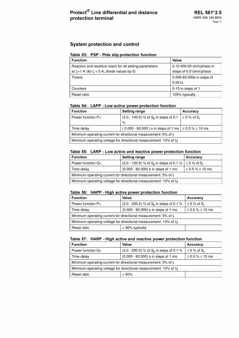
8/11/2019 1MRK506180-BEN a en Protect IT Line Differential and Distance Protection Terminal REL 561 2.5
http://slidepdf.com/reader/full/1mrk506180-ben-a-en-protect-it-line-differential-and-distance-protection-terminal 71/94
1MRK 506 180-BEN
Page 71
Reactive and resistive reach for all setting parametersat Ir=1 A (for I r = 5 A, divide values by 5)
0.10-400.00 ohm/phase insteps of 0.01ohm/phase
Timers 0.000-60.000s in steps of0.001s
Counters 0-10 in steps of 1
Reset ratio 105% typically
Power function P< (3.0 - 100.0) % of S b in steps of 0.1% ± 5 % of S r
Time delay ( 0.000 - 60.000 ) s in steps of 1 ms ± 0.5 % ± 10 ms
Minimum operating current for directional measurement: 5% of I r
Minimum operating voltage for directional measurement: 10% of U r
Power function Q< (3.0 - 100.0) % of S b in steps of 0.1 % ± 5 % of S r
Time delay (0.000 - 60.000) s in steps of 1 ms ± 0.5 % ± 10 ms
Minimum operating current for directional measurement: 5% of Ir
Minimum operating voltage for directional measurement: 10% of U r
Power function P> (3.0 - 200.0) % of S b in steps of 0.1 % ± 5 % of S r
Time delay (0.000 - 60.000) s in steps of 1 ms ± 0.5 % ± 10 ms
Minimum operating current for directional measurement: 5% of I r
Minimum operating voltage for directional measurement: 10% of U r
Reset ratio > 90% typically
Power function Q> (3.0 - 200.0) % of S b in steps of 0.1 % ± 5 % of S r
Time delay (0.000 - 60.000) s in steps of 1 ms ± 0.5 % ± 10 ms
Minimum operating current for directional measurement: 5% of I r
Minimum operating voltage for directional measurement: 10% of U r
Reset ratio > 90%

8/11/2019 1MRK506180-BEN a en Protect IT Line Differential and Distance Protection Terminal REL 561 2.5
http://slidepdf.com/reader/full/1mrk506180-ben-a-en-protect-it-line-differential-and-distance-protection-terminal 72/94
1MRK 506 180-BEN
Page 72
Change in current per power systemcycle, DIL>
20.0-100.0% of Ib in steps of0.1%
± 5.0 % of I r
Time delay for start signal, tHStart 0.000-60.000 s in steps of1 ms
± 0.5 % ± 10 ms
Time delay for trip signal, tHTrip 0.000-60.000 s in steps of1 ms
± 0.5 % ± 10 ms
Change in residual current perpower system cycle, DIN>
20.0-100.0% of Ib in steps of0.1%
± 5.0% of I r
Time delay for start signal, tHStart 0.000-60.000 s in steps of 1 ms ± 0.5 % ± 10 msTime delay for trip signal, tHTrip 0.000-60.000 s in steps of 1 ms + ± 0.5 % ± 10 ms
Change in voltage per power systemcycle, DUL>
5.0-100.0% of Ub in steps of0.1%
± 0.5 % of U r
Time delay for start signal, tHStart 0.000-60.000 s in steps of 1 ms ± 0.5 % ± 10 ms
Time delay for trip signal, tHTrip 0.000-60.000 s in steps of 1 ms ± 0.5 % ± 10 ms
Low-set operating value, ULLow> 80.0-150.0% of Ub insteps of 0.1%
± 2.5 % of U r
High-set operating value, ULHigh> 80.0-150.0% of Ub insteps of 0.1%
± 2.5 % of U r
Time delayed operation of low-set step, tLow 0.000-60.000 s insteps of 1 ms
± 0.5 % ± 10 ms
Time delayed operation of high-set step,tHigh
0.000-60.000 s insteps of 1 ms
± 0.5 % ± 10 ms
Low-set step of undercurrent limit, ILLow< 5.0-100.0% of Ib insteps of 0.1%
± 2.5 % of I r
High-set step of undercurrent limit, ILHigh< 5.0-100.0% of Ib insteps of 0.1%
± 2.5 % of I r
Time delayed operation of low-set step, tLow 0.000-60.000 s in stepsof 1 ms
± 0.5 % ± 10 ms
Time delayed operation of high-set step,tHigh
0.000-60.000 s in stepsof 1 ms
± 0.5 % ± 10 ms
Reset ratio > 106% typically
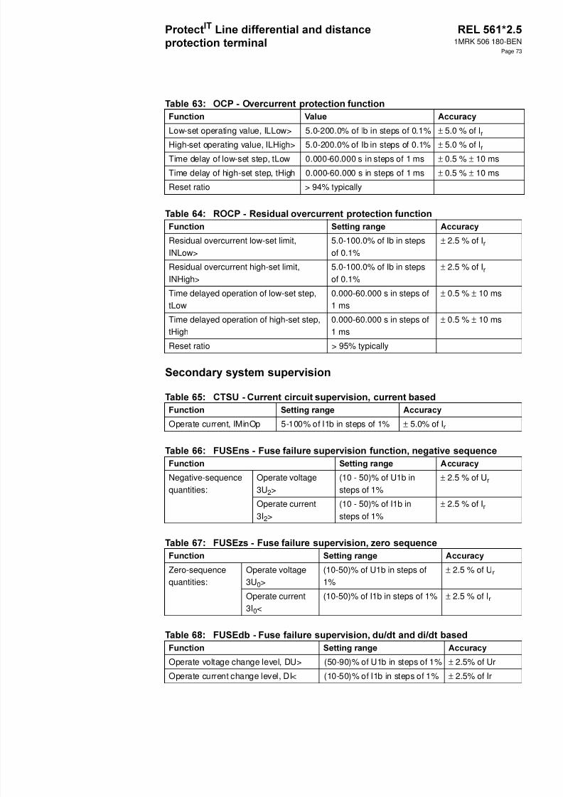
8/11/2019 1MRK506180-BEN a en Protect IT Line Differential and Distance Protection Terminal REL 561 2.5
http://slidepdf.com/reader/full/1mrk506180-ben-a-en-protect-it-line-differential-and-distance-protection-terminal 73/94
1MRK 506 180-BEN
Page 73
Low-set operating value, ILLow> 5.0-200.0% of Ib in steps of 0.1% ± 5.0 % of I r
High-set operating value, ILHigh> 5.0-200.0% of Ib in steps of 0.1% ± 5.0 % of I r
Time delay of low-set step, tLow 0.000-60.000 s in steps of 1 ms ± 0.5 % ± 10 ms
Time delay of high-set step, tHigh 0.000-60.000 s in steps of 1 ms ± 0.5 % ± 10 ms
Reset ratio > 94% typically
Residual overcurrent low-set limit,INLow>
5.0-100.0% of Ib in stepsof 0.1%
± 2.5 % of I r
Residual overcurrent high-set limit,
INHigh>
5.0-100.0% of Ib in steps
of 0.1%
± 2.5 % of I r
Time delayed operation of low-set step,tLow
0.000-60.000 s in steps of1 ms
± 0.5 % ± 10 ms
Time delayed operation of high-set step,tHigh
0.000-60.000 s in steps of1 ms
± 0.5 % ± 10 ms
Reset ratio > 95% typically
Operate current, IMinOp 5-100% of I1b in steps of 1% ± 5.0 % of I r
Negative-sequencequantities:
Operate voltage3U2>
(10 - 50)% of U1b insteps of 1%
± 2.5 % of U r
Operate current3I2>
(10 - 50)% of I1b insteps of 1%
± 2.5 % of I r
Zero-sequencequantities:
Operate voltage3U0>
(10-50)% of U1b in steps of1%
± 2.5 % of U r
Operate current3I0<
(10-50)% of I1b in steps of 1% ± 2.5 % of I r
Operate voltage change level, DU> (50-90)% of U1b in steps of 1% ± 2.5% of Ur
Operate current change level, DI< (10-50)% of I1b in steps of 1% ± 2.5% of Ir
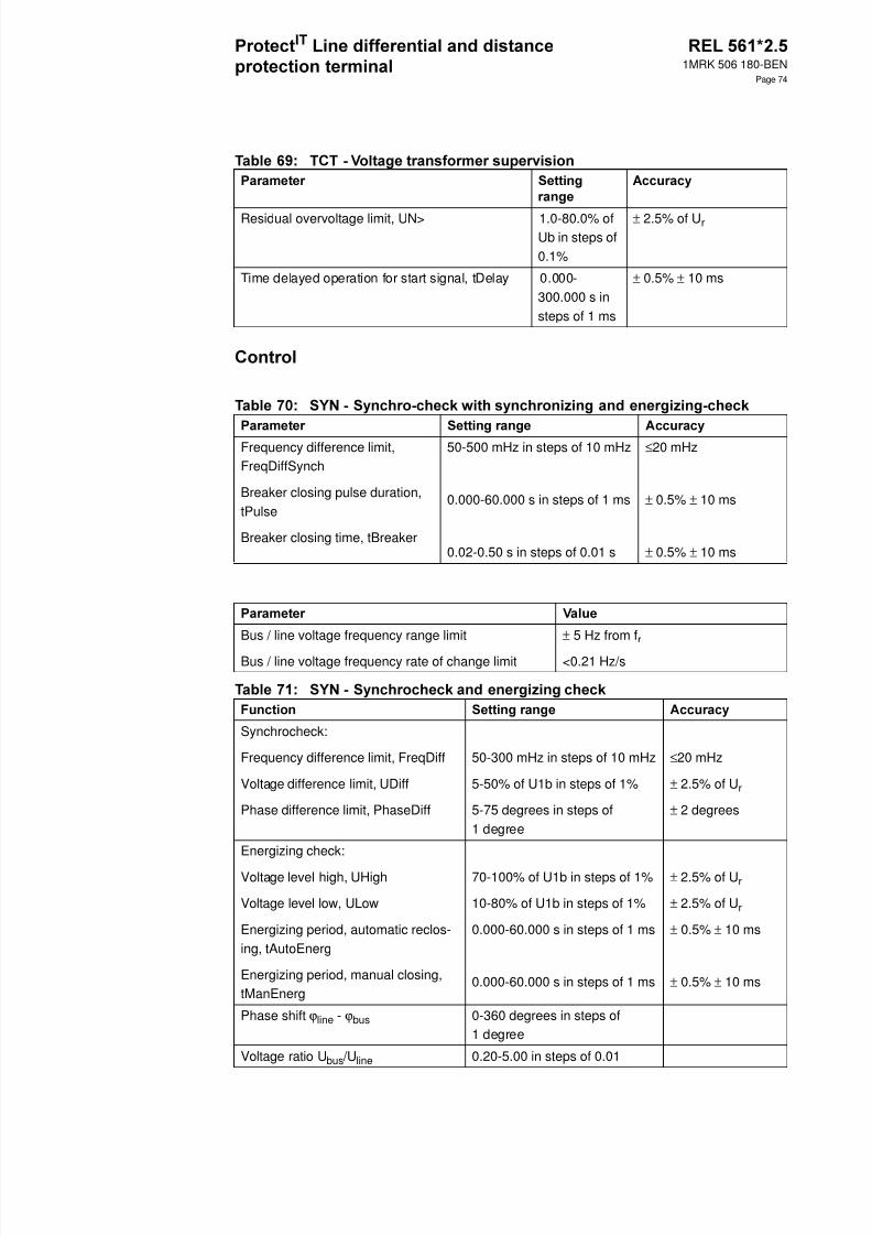
8/11/2019 1MRK506180-BEN a en Protect IT Line Differential and Distance Protection Terminal REL 561 2.5
http://slidepdf.com/reader/full/1mrk506180-ben-a-en-protect-it-line-differential-and-distance-protection-terminal 74/94
1MRK 506 180-BEN
Page 74
Residual overvoltage limit, UN> 1.0-80.0% ofUb in steps of0.1%
± 2.5% of U r
Time delayed operation for start signal, tDelay 0.000-300.000 s insteps of 1 ms
± 0.5% ± 10 ms
Frequency difference limit,FreqDiffSynch
Breaker closing pulse duration,tPulse
Breaker closing time, tBreaker
50-500 mHz in steps of 10 mHz
0.000-60.000 s in steps of 1 ms
0.02-0.50 s in steps of 0.01 s
≤20 mHz
± 0.5% ± 10 ms
± 0.5% ± 10 ms
Bus / line voltage frequency range limit
Bus / line voltage frequency rate of change limit
± 5 Hz from f r
<0.21 Hz/s
Synchrocheck:
Frequency difference limit, FreqDiff
Voltage difference limit, UDiff
Phase difference limit, PhaseDiff
50-300 mHz in steps of 10 mHz
5-50% of U1b in steps of 1%
5-75 degrees in steps of1 degree
≤20 mHz
± 2.5% of U r
± 2 degrees
Energizing check:
Voltage level high, UHigh
Voltage level low, ULow
Energizing period, automatic reclos-ing, tAutoEnerg
Energizing period, manual closing,tManEnerg
70-100% of U1b in steps of 1%
10-80% of U1b in steps of 1%
0.000-60.000 s in steps of 1 ms
0.000-60.000 s in steps of 1 ms
± 2.5% of U r
± 2.5% of U r
± 0.5% ± 10 ms
± 0.5% ± 10 ms
Phase shift ϕline - ϕbus 0-360 degrees in steps of1 degree
Voltage ratio U bus /Uline 0.20-5.00 in steps of 0.01
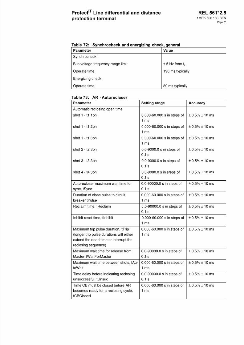
8/11/2019 1MRK506180-BEN a en Protect IT Line Differential and Distance Protection Terminal REL 561 2.5
http://slidepdf.com/reader/full/1mrk506180-ben-a-en-protect-it-line-differential-and-distance-protection-terminal 75/94
1MRK 506 180-BEN
Page 75
Synchrocheck:
Bus voltage frequency range limit
Operate time
Energizing check:
Operate time
± 5 Hz from f r
190 ms typically
80 ms typically
Automatic reclosing open time:
shot 1 - t1 1ph 0.000-60.000 s in steps of
1 ms
± 0.5% ± 10 ms
shot 1 - t1 2ph 0.000-60.000 s in steps of1 ms
± 0.5% ± 10 ms
shot 1 - t1 3ph 0.000-60.000 s in steps of1 ms
± 0.5% ± 10 ms
shot 2 - t2 3ph 0.0-9000.0 s in steps of0.1 s
± 0.5% ± 10 ms
shot 3 - t3 3ph 0.0-9000.0 s in steps of0.1 s
± 0.5% ± 10 ms
shot 4 - t4 3ph 0.0-9000.0 s in steps of0.1 s
± 0.5% ± 10 ms
Autorecloser maximum wait time forsync, tSync
0.0-90000.0 s in steps of0.1 s
± 0.5% ± 10 ms
Duration of close pulse to circuitbreaker tPulse
0.000-60.000 s in steps of1 ms
± 0.5% ± 10 ms
Reclaim time, tReclaim 0.0-90000.0 s in steps of0.1 s
± 0.5% ± 10 ms
Inhibit reset time, tInhibit 0.000-60.000 s in steps of1 ms
± 0.5% ± 10 ms
Maximum trip pulse duration, tTrip(longer trip pulse durations will eitherextend the dead time or interrupt thereclosing sequence)
0.000-60.000 s in steps of1 ms
± 0.5% ± 10 ms
Maximum wait time for release fromMaster, tWaitForMaster
0.0-90000.0 s in steps of0.1 s
± 0.5% ± 10 ms
Maximum wait time between shots, tAu-toWait
0.000-60.000 s in steps of1 ms
± 0.5% ± 10 ms
Time delay before indicating reclosingunsuccessful, tUnsuc
0.0-90000.0 s in steps of0.1 s
± 0.5% ± 10 ms
Time CB must be closed before ARbecomes ready for a reclosing cycle,tCBClosed
0.000-60.000 s in steps of1 ms
± 0.5% ± 10 ms
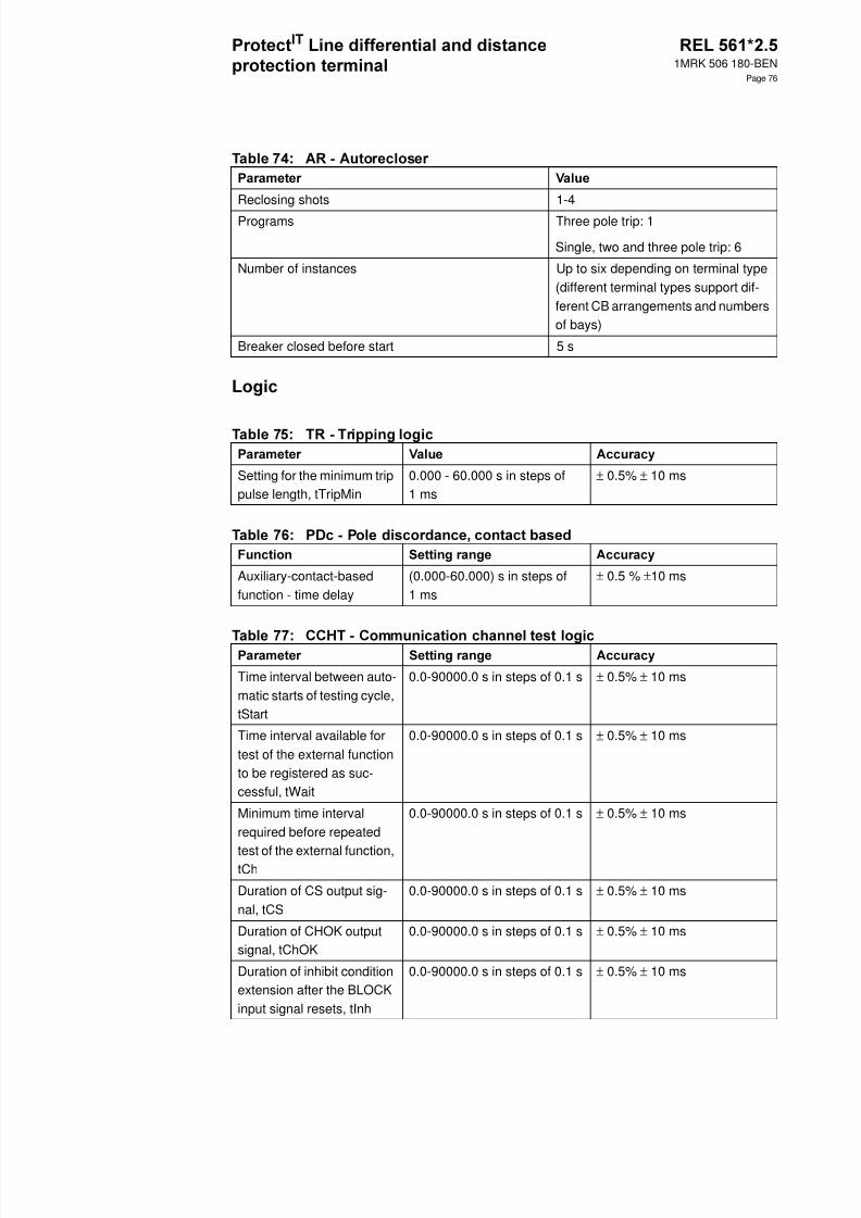
8/11/2019 1MRK506180-BEN a en Protect IT Line Differential and Distance Protection Terminal REL 561 2.5
http://slidepdf.com/reader/full/1mrk506180-ben-a-en-protect-it-line-differential-and-distance-protection-terminal 76/94
1MRK 506 180-BEN
Page 76
Reclosing shots 1-4
Programs Three pole trip: 1
Single, two and three pole trip: 6
Number of instances Up to six depending on terminal type(different terminal types support dif-ferent CB arrangements and numbersof bays)
Breaker closed before start 5 s
Setting for the minimum trippulse length, tTripMin
0.000 - 60.000 s in steps of1 ms
± 0.5% ± 10 ms
Auxiliary-contact-basedfunction - time delay
(0.000-60.000) s in steps of1 ms
± 0.5 % ±10 ms
Time interval between auto-matic starts of testing cycle,tStart
0.0-90000.0 s in steps of 0.1 s ± 0.5% ± 10 ms
Time interval available fortest of the external functionto be registered as suc-cessful, tWait
0.0-90000.0 s in steps of 0.1 s ± 0.5% ± 10 ms
Minimum time intervalrequired before repeated
test of the external function,tCh
0.0-90000.0 s in steps of 0.1 s ± 0.5% ± 10 ms
Duration of CS output sig-nal, tCS
0.0-90000.0 s in steps of 0.1 s ± 0.5% ± 10 ms
Duration of CHOK outputsignal, tChOK
0.0-90000.0 s in steps of 0.1 s ± 0.5% ± 10 ms
Duration of inhibit conditionextension after the BLOCKinput signal resets, tInh
0.0-90000.0 s in steps of 0.1 s ± 0.5% ± 10 ms

8/11/2019 1MRK506180-BEN a en Protect IT Line Differential and Distance Protection Terminal REL 561 2.5
http://slidepdf.com/reader/full/1mrk506180-ben-a-en-protect-it-line-differential-and-distance-protection-terminal 77/94
1MRK 506 180-BEN
Page 77
Counter value 0-10000
Max. count up speed 10 pulses/s
Pre-fault time, tPre 50-300 ms in steps of 10 ms
Post-fault time, tPost 100-5000 ms in steps of 100 ms
Limit time, tLim 500-6000 ms in steps of 100 ms
Number of recorded disturbances Max. 10
Overcurrent triggering 0-5000% of Inb insteps of 1%
Undercurrent triggering 0-200% of Inb insteps of 1%
Overvoltage triggering 0-200% of Unb insteps of 1% at 100 Vsec.
Undervoltage triggering 0-110% of Unb insteps of 1%
Number of binary signals 48
Number of analog signals 10
Sampling rate 2 kHz
Recording bandwidth 5-250 Hz
Total recording time with ten analog and 48 binary signals recorded.(The amount of harmonics can affect the maximum storage time)
40 s typically
Voltage channels Dynamic range (0.01-2.00) x U r at100/200 V sec.
Resolution 0.1% of U r
Accuracy at ratedfrequency
U ≤ Ur ± 2.5% of U r
U > U r ± 2.5% of U

8/11/2019 1MRK506180-BEN a en Protect IT Line Differential and Distance Protection Terminal REL 561 2.5
http://slidepdf.com/reader/full/1mrk506180-ben-a-en-protect-it-line-differential-and-distance-protection-terminal 78/94
1MRK 506 180-BEN
Page 78
Current channels Dynamic range Without DC off-set
(0.01-110.00) × Ir
With full DC off-set
(0.01-60.00) × Ir
Resolution 0.5 % of I r
Accuracy at ratedfrequency
I ≤ Ir ± 2.5 % of I r
I > Ir ± 2.5 % of I
Event buffering capacity Max. number of events/disturbance report 150
Max. number of disturbance reports 10
Distance to faultlocator
Reach for I r =1 A
Resistive direc-tion
(0 - 1500) ohm/ phase
± 2.5 % (typical)
Reactive direc-tion
(0 - 1500) ohm/ phase
± 2.5 % (typical)
Phase selection According toinput signals
Frequency (0.95 - 1.05) x f r ± 0.2 Hz
Voltage (RMS) Ph-Ph (0.1 - 1.5) x U r ± 2.5% of U r, at U ≤ Ur
± 2.5% of U, at U> U r
Current (RMS) (0.2 - 4) x I r ± 2.5% of I r, at I ≤ Ir
± 2.5% of I, at I> I r
Active power *) at |cos ϕ| ≥ 0.9 ± 5.0%
Reactive power *) at |cos ϕ| ≤ 0.8 ± 7.5%
*) Measured at U r and 20% of I r
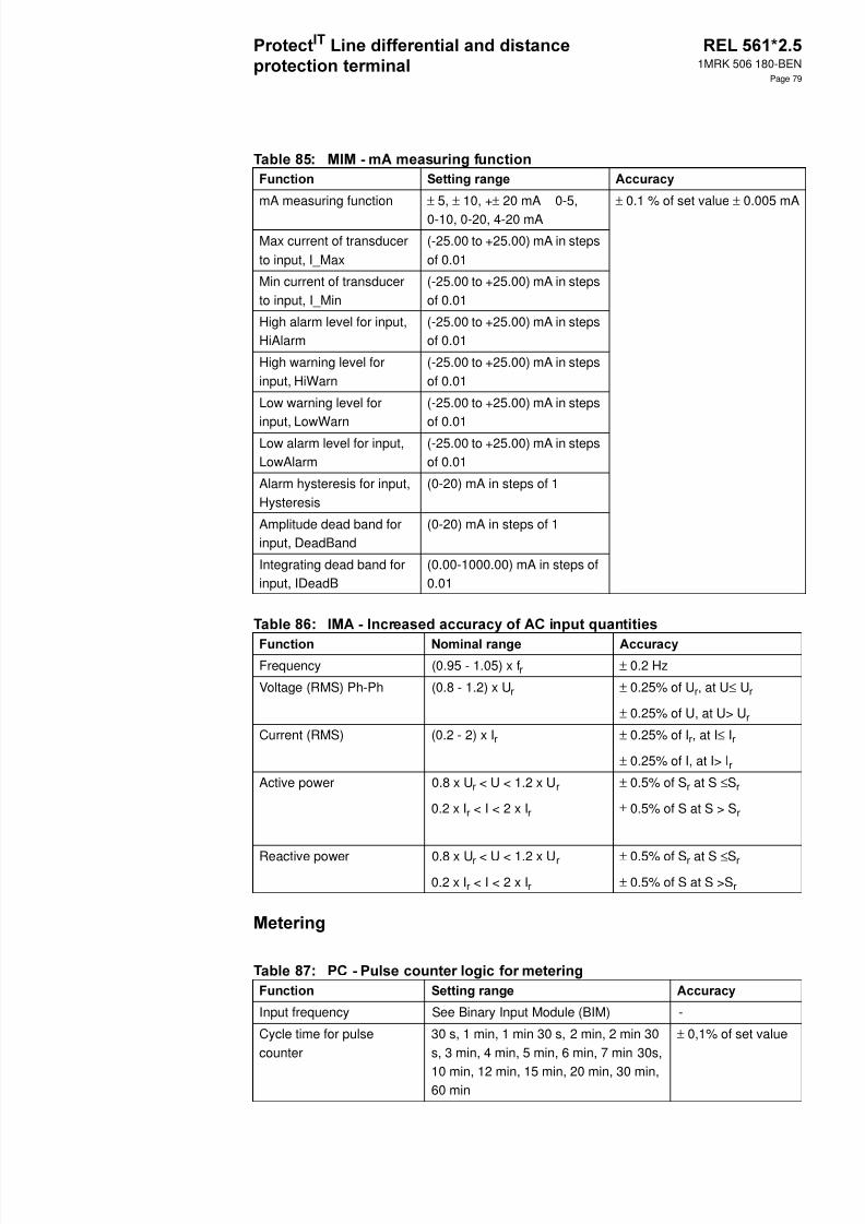
8/11/2019 1MRK506180-BEN a en Protect IT Line Differential and Distance Protection Terminal REL 561 2.5
http://slidepdf.com/reader/full/1mrk506180-ben-a-en-protect-it-line-differential-and-distance-protection-terminal 79/94
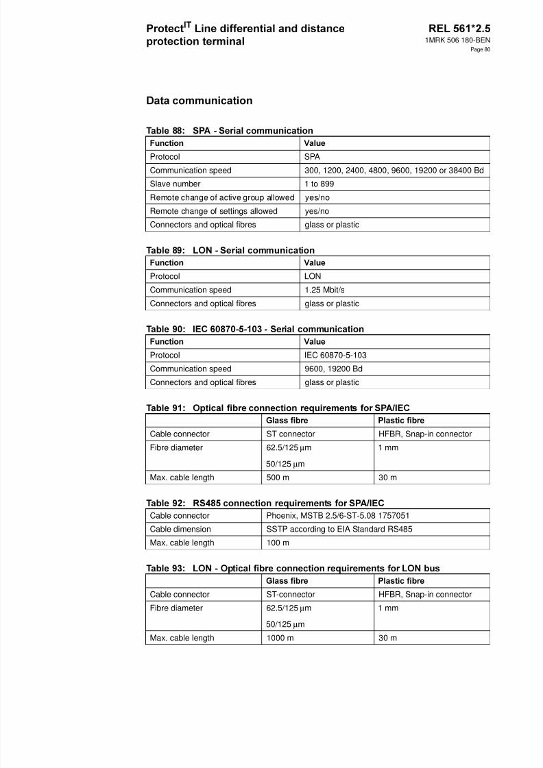
8/11/2019 1MRK506180-BEN a en Protect IT Line Differential and Distance Protection Terminal REL 561 2.5
http://slidepdf.com/reader/full/1mrk506180-ben-a-en-protect-it-line-differential-and-distance-protection-terminal 80/94
1MRK 506 180-BEN
Page 80
Protocol SPA
Communication speed 300, 1200, 2400, 4800, 9600, 19200 or 38400 Bd
Slave number 1 to 899
Remote change of active group allowed yes/no
Remote change of settings allowed yes/no
Connectors and optical fibres glass or plastic
Protocol LON
Communication speed 1.25 Mbit/s
Connectors and optical fibres glass or plastic
Protocol IEC 60870-5-103
Communication speed 9600, 19200 Bd
Connectors and optical fibres glass or plastic
Cable connector ST connector HFBR, Snap-in connector
Fibre diameter 62.5/125 µm
50/125 µm
1 mm
Max. cable length 500 m 30 m
Cable connector Phoenix, MSTB 2.5/6-ST-5.08 1757051
Cable dimension SSTP according to EIA Standard RS485
Max. cable length 100 m
Cable connector ST-connector HFBR, Snap-in connector
Fibre diameter 62.5/125 µm
50/125 µm
1 mm
Max. cable length 1000 m 30 m
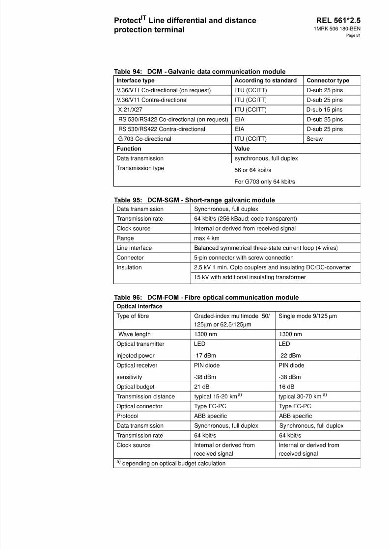
8/11/2019 1MRK506180-BEN a en Protect IT Line Differential and Distance Protection Terminal REL 561 2.5
http://slidepdf.com/reader/full/1mrk506180-ben-a-en-protect-it-line-differential-and-distance-protection-terminal 81/94
1MRK 506 180-BEN
Page 81
V.36/V11 Co-directional (on request) ITU (CCITT) D-sub 25 pins
V.36/V11 Contra-directional ITU (CCITT) D-sub 25 pins
X.21/X27 ITU (CCITT) D-sub 15 pins
RS 530/RS422 Co-directional (on request) EIA D-sub 25 pins
RS 530/RS422 Contra-directional EIA D-sub 25 pins
G.703 Co-directional ITU (CCITT) Screw
Data transmission synchronous, full duplex
56 or 64 kbit/s
For G703 only 64 kbit/s
Transmission type
Data transmission Synchronous, full duplex
Transmission rate 64 kbit/s (256 kBaud; code transparent)
Clock source Internal or derived from received signal
Range max 4 km
Line interface Balanced symmetrical three-state current loop (4 wires)
Connector 5-pin connector with screw connection
Insulation 2,5 kV 1 min. Opto couplers and insulating DC/DC-converter
15 kV with additional insulating transformer
Type of fibre Graded-index multimode 50/ 125 µm or 62,5/125 µm
Single mode 9/125 µm
Wave length 1300 nm 1300 nm
Optical transmitter
injected power
LED
-17 dBm
LED
-22 dBm
Optical receiver
sensitivity
PIN diode
-38 dBm
PIN diode
-38 dBm
Optical budget 21 dB 16 dBTransmission distance typical 15-20 km a) typical 30-70 km a)
Optical connector Type FC-PC Type FC-PC
Protocol ABB specific ABB specific
Data transmission Synchronous, full duplex Synchronous, full duplex
Transmission rate 64 kbit/s 64 kbit/s
Clock source Internal or derived fromreceived signal
Internal or derived fromreceived signal
a) depending on optical budget calculation
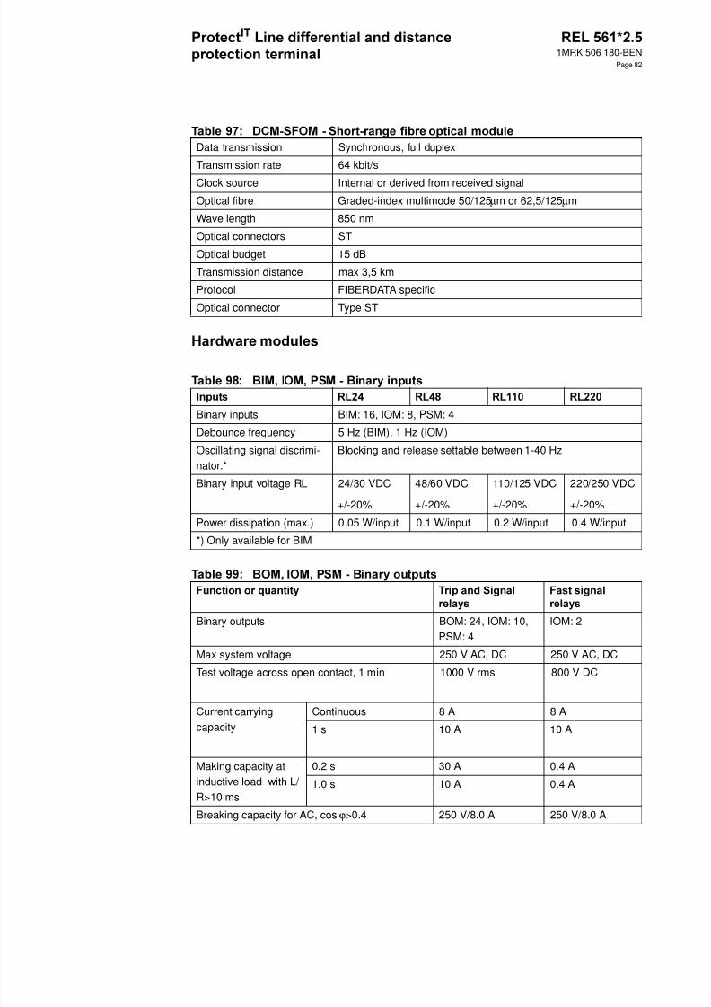
8/11/2019 1MRK506180-BEN a en Protect IT Line Differential and Distance Protection Terminal REL 561 2.5
http://slidepdf.com/reader/full/1mrk506180-ben-a-en-protect-it-line-differential-and-distance-protection-terminal 82/94
1MRK 506 180-BEN
Page 82
Data transmission Synchronous, full duplex
Transmission rate 64 kbit/s
Clock source Internal or derived from received signal
Optical fibre Graded-index multimode 50/125 µm or 62,5/125 µm
Wave length 850 nm
Optical connectors ST
Optical budget 15 dB
Transmission distance max 3,5 km
Protocol FIBERDATA specific
Optical connector Type ST
Binary inputs BIM: 16, IOM: 8, PSM: 4
Debounce frequency 5 Hz (BIM), 1 Hz (IOM)
Oscillating signal discrimi-nator.*
Blocking and release settable between 1-40 Hz
Binary input voltage RL 24/30 VDC
+/-20%
48/60 VDC
+/-20%
110/125 VDC
+/-20%
220/250 VDC
+/-20%
Power dissipation (max.) 0.05 W/input 0.1 W/input 0.2 W/input 0.4 W/input
*) Only available for BIM
Binary outputs BOM: 24, IOM: 10,PSM: 4
IOM: 2
Max system voltage 250 V AC, DC 250 V AC, DC
Test voltage across open contact, 1 min 1000 V rms 800 V DC
Current carryingcapacity
Continuous 8 A 8 A
1 s 10 A 10 A
Making capacity atinductive load with L/ R>10 ms
0.2 s 30 A 0.4 A
1.0 s 10 A 0.4 A
Breaking capacity for AC, cos ϕ>0.4 250 V/8.0 A 250 V/8.0 A
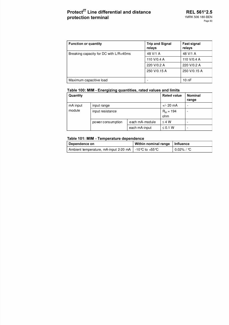
8/11/2019 1MRK506180-BEN a en Protect IT Line Differential and Distance Protection Terminal REL 561 2.5
http://slidepdf.com/reader/full/1mrk506180-ben-a-en-protect-it-line-differential-and-distance-protection-terminal 83/94
1MRK 506 180-BEN
Page 83
Breaking capacity for DC with L/R<40ms 48 V/1 A 48 V/1 A
110 V/0.4 A 110 V/0.4 A
220 V/0.2 A 220 V/0.2 A
250 V/0.15 A 250 V/0.15 A
Maximum capacitive load - 10 nF
mA inputmodule
input range +/- 20 mA -
input resistance R in = 194ohm
-
power consumption each mA-module ≤ 4 W -
each mA-input ≤ 0.1 W -
Ambient temperature, mA-input 2-20 mA -10°C to +55°C 0.02% / °C
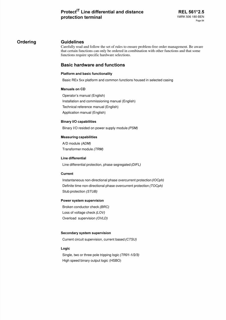
8/11/2019 1MRK506180-BEN a en Protect IT Line Differential and Distance Protection Terminal REL 561 2.5
http://slidepdf.com/reader/full/1mrk506180-ben-a-en-protect-it-line-differential-and-distance-protection-terminal 84/94
1MRK 506 180-BEN
Page 84
Carefully read and follow the set of rules to ensure problem-free order management. Be awarethat certain functions can only be ordered in combination with other functions and that some
functions require specific hardware selections.
Basic REx 5xx platform and common functions housed in selected casing
Operator’s manual (English)
Installation and commissioning manual (English)
Technical reference manual (English)
Application manual (English)
Binary I/O resided on power supply module
A/D module
Transformer module
Line differential protection, phase segregated
Instantaneous non-directional phase overcurrent protection
Definite time non-directional phase overcurrent protection
Stub protection
Broken conductor check
Loss of voltage check
Overload supervision
Current circuit supervision, current based
Single, two or three pole tripping logic
High speed binary output logic (HSBO)

8/11/2019 1MRK506180-BEN a en Protect IT Line Differential and Distance Protection Terminal REL 561 2.5
http://slidepdf.com/reader/full/1mrk506180-ben-a-en-protect-it-line-differential-and-distance-protection-terminal 85/94
1MRK 506 180-BEN
Page 85
Event recorder
Supervision of AC input quantities
Supervision of mA input quantities (Requires optional mA-transducer module, )
REL 561 Quantity: 1MRK 002 496-AE
Default:
The terminal is delivered without loaded configuration.
Option:
Customer specific configuration On request
Engergizing quantities for binary inputs onpower supply module
24-30 V 1MRK 002 238-AA
48-60 V 1MRK 002 238-BA
110-125 V 1MRK 002 238-CA
220-250 V 1MRK 002 238-DA

8/11/2019 1MRK506180-BEN a en Protect IT Line Differential and Distance Protection Terminal REL 561 2.5
http://slidepdf.com/reader/full/1mrk506180-ben-a-en-protect-it-line-differential-and-distance-protection-terminal 86/94
1MRK 506 180-BEN
Page 86
Add measuring capabilities by selecting input energizing options from the following tables.
Rated measuring input energizing quantities 1 A, 110 V 1MRK 000 157-MB
1 A, 220 V 1MRK 000 157-VB
5 A, 110 V 1MRK 000 157-NB
5 A, 220 V 1MRK 000 157-WB
Rated measuring input energizingquantities for sensitive earth faultfunctions
I1-I4
I5
U1-U5
1 A
0.1 A
110 V
1MRK 000 157-XB
I1-I4
I5
U1-U5
5 A
0.5 A
110 V
1MRK 000 157-RB
Full scheme distance protection, 3-zone, phase-to-phase 1MRK 001 456-CA
Full scheme distance protection, 3-zone, phase-to-earth 1MRK 001 456-DA
Simplified impedance settings 1MRK 001 459-UA
Additions for series-compensated networks 1MRK 001 456-EA
Phase selection logic 1MRK 001 456-KA
Power swing detection 1MRK 001 456-LA
Power swing additional logic 1MRK 001 456-SA
Scheme communication logic 1MRK 001 456-NA
Current reversal and weak end infeed logic 1MRK 001 455-PA
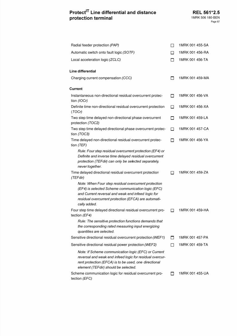
8/11/2019 1MRK506180-BEN a en Protect IT Line Differential and Distance Protection Terminal REL 561 2.5
http://slidepdf.com/reader/full/1mrk506180-ben-a-en-protect-it-line-differential-and-distance-protection-terminal 87/94
1MRK 506 180-BEN
Page 87
Radial feeder protection 1MRK 001 455-SA
Automatic switch onto fault logic 1MRK 001 456-RA
Local acceleration logic 1MRK 001 456-TA
Charging current compensation 1MRK 001 459-MA
Instantaneous non-directional residual overcurrent protec-tion
1MRK 001 456-VA
Definite time non-directional residual overcurrent protection(
1MRK 001 456-XA
Two step time delayed non-directional phase overcurrentprotection
1MRK 001 459-LA
Two step time delayed directional phase overcurrent protec-tion
1MRK 001 457-CA
Time delayed non-directional residual overcurrent protec-tion
1MRK 001 456-YA
Time delayed directional residual overcurrent protection 1MRK 001 459-ZA
Four step time delayed directional residual overcurrent pro-tection
1MRK 001 459-HA
Sensitive directional residual overcurrent protection 1MRK 001 457-PA
Sensitive directional residual power protection 1MRK 001 459-TA
.
Scheme communication logic for residual overcurrent pro-tection
1MRK 001 455-UA
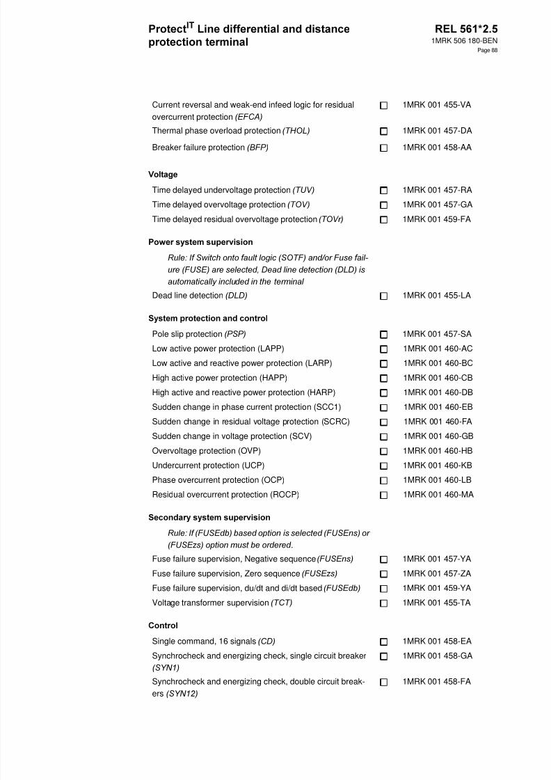
8/11/2019 1MRK506180-BEN a en Protect IT Line Differential and Distance Protection Terminal REL 561 2.5
http://slidepdf.com/reader/full/1mrk506180-ben-a-en-protect-it-line-differential-and-distance-protection-terminal 88/94
1MRK 506 180-BEN
Page 88
Current reversal and weak-end infeed logic for residualovercurrent protection
1MRK 001 455-VA
Thermal phase overload protection 1MRK 001 457-DA
Breaker failure protection 1MRK 001 458-AA
Time delayed undervoltage protection 1MRK 001 457-RA
Time delayed overvoltage protection 1MRK 001 457-GA
Time delayed residual overvoltage protection 1MRK 001 459-FA
Dead line detection 1MRK 001 455-LA
Pole slip protection 1MRK 001 457-SA
Low active power protection (LAPP) 1MRK 001 460-AC
Low active and reactive power protection (LARP) 1MRK 001 460-BC
High active power protection (HAPP) 1MRK 001 460-CB
High active and reactive power protection (HARP) 1MRK 001 460-DB
Sudden change in phase current protection (SCC1) 1MRK 001 460-EBSudden change in residual voltage protection (SCRC) 1MRK 001 460-FA
Sudden change in voltage protection (SCV) 1MRK 001 460-GB
Overvoltage protection (OVP) 1MRK 001 460-HB
Undercurrent protection (UCP) 1MRK 001 460-KB
Phase overcurrent protection (OCP) 1MRK 001 460-LB
Residual overcurrent protection (ROCP) 1MRK 001 460-MA
.Fuse failure supervision, Negative sequence 1MRK 001 457-YA
Fuse failure supervision, Zero sequence 1MRK 001 457-ZA
Fuse failure supervision, du/dt and di/dt based 1MRK 001 459-YA
Voltage transformer supervision 1MRK 001 455-TA
Single command, 16 signals 1MRK 001 458-EA
Synchrocheck and energizing check, single circuit breaker 1MRK 001 458-GA
Synchrocheck and energizing check, double circuit break-ers
1MRK 001 458-FA

8/11/2019 1MRK506180-BEN a en Protect IT Line Differential and Distance Protection Terminal REL 561 2.5
http://slidepdf.com/reader/full/1mrk506180-ben-a-en-protect-it-line-differential-and-distance-protection-terminal 89/94
1MRK 506 180-BEN
Page 89
Synchrocheck with synchronizing and energizing check,single circuit breaker
1MRK 001 458-KA
Synchrocheck with synchronizing and energizing check,double circuit breaker
1MRK 001 457-HA
Autorecloser - 1- and/or 3-phase, single circuit breaker 1MRK 001 458-LA
Autorecloser - 1- and/or 3-phase, double circuit breakers 1MRK 001 457-KA
Autorecloser - 3-phase, single circuit breaker 1MRK 001 458-MA
Autorecloser- 3-phase, double circuit breaker 1MRK 001 457-LA
Additional single, two or three pole tripping logic 1MRK 001 459-XA
Pole discordance logic (contact based) 1MRK 001 458-UA
Additional configurable logic blocks 1MRK 001 457-MA
Communication channel test logic 1MRK 001 459-NA
Multiple command, one fast block with 16 signals (CM1) 1MRK 001 455-RA
Multiple command, 79 medium speed blocks each with 16signals
1MRK 001 458-YA
Disturbance recorder 1MRK 001 458-NA
Fault locator 1MRK 001 458-RA
Trip value recorder 1MRK 001 458-SA
Increased accuracy of AC input quantities 1MRK 000 597-PA
Pulse counter logic for metering 1MRK 001 458-TA
Six event counters 1MRK 001 445-CA
2nd HMI language, german German 1MRK 001 459-AA
2nd HMI language, russian Russian 1MRK 001 459-BA
2nd HMI language, french French 1MRK 001 459-CA
2nd HMI language, spanish Spanish 1MRK 001 459-DA
2nd HMI language, italian Italian 1MRK 001 459-EA
Customer specific language Contact your local ABB representative foravailability
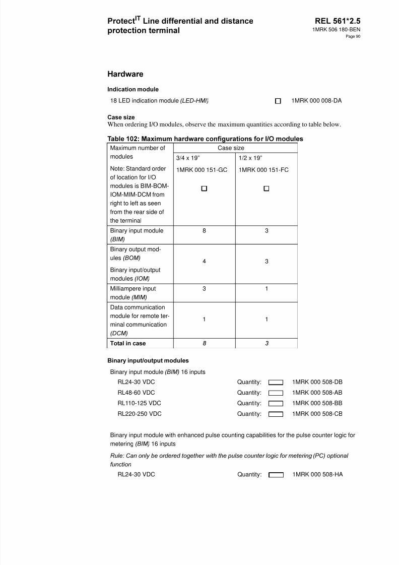
8/11/2019 1MRK506180-BEN a en Protect IT Line Differential and Distance Protection Terminal REL 561 2.5
http://slidepdf.com/reader/full/1mrk506180-ben-a-en-protect-it-line-differential-and-distance-protection-terminal 90/94
1MRK 506 180-BEN
Page 90
When ordering I/O modules, observe the maximum quantities according to table below.
18 LED indication module 1MRK 000 008-DA
Maximum number ofmodules
Note: Standard orderof location for I/Omodules is BIM-BOM-IOM-MIM-DCM fromright to left as seenfrom the rear side ofthe terminal
Case size
3/4 x 19”
1MRK 000 151-GC
1/2 x 19”
1MRK 000 151-FC
Binary input module 8 3
Binary output mod-ules
Binary input/outputmodules
4 3
Milliampere input
module
3 1
Data communicationmodule for remote ter-minal communication
1 1
Binary input module 16 inputs
RL24-30 VDC Quantity: 1MRK 000 508-DB
RL48-60 VDC Quantity: 1MRK 000 508-AB
RL110-125 VDC Quantity: 1MRK 000 508-BB
RL220-250 VDC Quantity: 1MRK 000 508-CB
Binary input module with enhanced pulse counting capabilities for the pulse counter logic formetering 16 inputs
RL24-30 VDC Quantity: 1MRK 000 508-HA

8/11/2019 1MRK506180-BEN a en Protect IT Line Differential and Distance Protection Terminal REL 561 2.5
http://slidepdf.com/reader/full/1mrk506180-ben-a-en-protect-it-line-differential-and-distance-protection-terminal 91/94
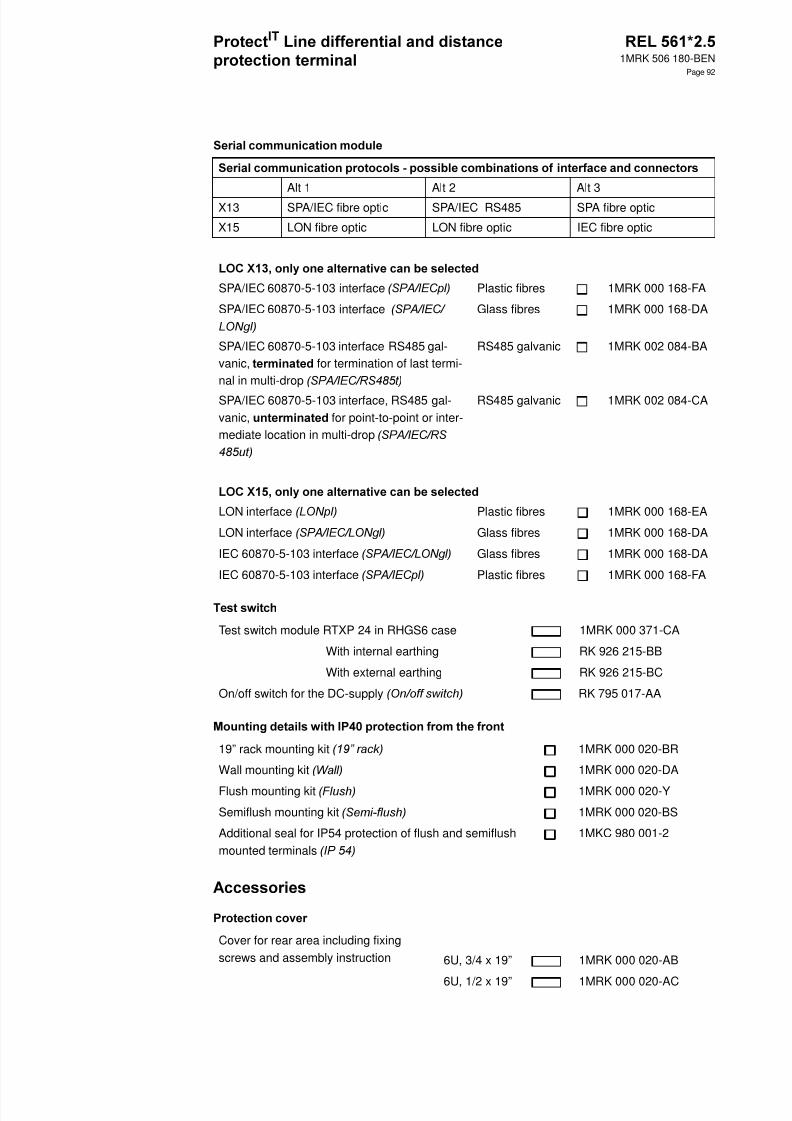
8/11/2019 1MRK506180-BEN a en Protect IT Line Differential and Distance Protection Terminal REL 561 2.5
http://slidepdf.com/reader/full/1mrk506180-ben-a-en-protect-it-line-differential-and-distance-protection-terminal 92/94
1MRK 506 180-BEN
Page 92
Alt 1 Alt 2 Alt 3
X13 SPA/IEC fibre optic SPA/IEC RS485 SPA fibre optic
X15 LON fibre optic LON fibre optic IEC fibre optic
SPA/IEC 60870-5-103 interface Plastic fibres 1MRK 000 168-FA
SPA/IEC 60870-5-103 interface Glass fibres 1MRK 000 168-DA
SPA/IEC 60870-5-103 interface RS485 gal-vanic, for termination of last termi-nal in multi-drop
RS485 galvanic 1MRK 002 084-BA
SPA/IEC 60870-5-103 interface, RS485 gal-vanic, for point-to-point or inter-mediate location in multi-drop
RS485 galvanic 1MRK 002 084-CA
LON interface Plastic fibres 1MRK 000 168-EA
LON interface Glass fibres 1MRK 000 168-DA
IEC 60870-5-103 interface Glass fibres 1MRK 000 168-DA
IEC 60870-5-103 interface Plastic fibres 1MRK 000 168-FA
Test switch module RTXP 24 in RHGS6 case 1MRK 000 371-CA
With internal earthing RK 926 215-BB
With external earthing RK 926 215-BC
On/off switch for the DC-supply RK 795 017-AA
19” rack mounting kit 1MRK 000 020-BR
Wall mounting kit 1MRK 000 020-DA
Flush mounting kit 1MRK 000 020-Y
Semiflush mounting kit 1MRK 000 020-BS
Additional seal for IP54 protection of flush and semiflushmounted terminals
1MKC 980 001-2
Cover for rear area including fixingscrews and assembly instruction 6U, 3/4 x 19” 1MRK 000 020-AB
6U, 1/2 x 19” 1MRK 000 020-AC

8/11/2019 1MRK506180-BEN a en Protect IT Line Differential and Distance Protection Terminal REL 561 2.5
http://slidepdf.com/reader/full/1mrk506180-ben-a-en-protect-it-line-differential-and-distance-protection-terminal 93/94
1MRK 506 180-BEN
Page 93
Side-by-side mounting kit 1MRK 000 020-Z
21-15X: Optical/electrical converter for short range fibreoptical module V.36 (supply 48-110 VDC)
1MRK 001 295-CA
21-16X: Optical/electrical converter for short range fibreoptical module X.21/G 703 (supply 48-110 VDC)
1MRK 001 295-DA
Key switch for restriction of settings via LCD-HMI
Quantity: 1MRK 000 611-A
Front connection cable between LCD-HMIand PC for terminal handling (Opto/9-pole D-sub)
Quantity: 1MKC 950 001-2
User documentation CD-ROM REx 5xx, RET
521, RED 521 (DOC-CD)
Quantity: 1MRK 002 270-AA
Operator’s manual Quantity: 1MRK 506 181-UEN
Technical reference manual Quantity: 1MRK 506 182-UEN
Installation and commissioning manual Quantity: 1MRK 506 183-UEN
Application manual Quantity: 1MRK 506 184-UEN
For our reference and statistics we would be pleased to be provided with the following applica-tion data:
Country: End user:
Station name: Voltage level: kV

8/11/2019 1MRK506180-BEN a en Protect IT Line Differential and Distance Protection Terminal REL 561 2.5
http://slidepdf.com/reader/full/1mrk506180-ben-a-en-protect-it-line-differential-and-distance-protection-terminal 94/94