10/2/0810/2/2008ECE 561 -ECE 561 - Lecture 51 State Machine Implementation 10/2/20081ECE 561 -...
16
10/2/0810/2/2008 ECE 561 -ECE 561 - Lecture 5 1 State Machine Implementation 10/2/2008 1 ECE 561 - Lecture 5
-
Upload
susan-barley -
Category
Documents
-
view
220 -
download
0
Transcript of 10/2/0810/2/2008ECE 561 -ECE 561 - Lecture 51 State Machine Implementation 10/2/20081ECE 561 -...
10/2/0810/2/2008 ECE 561 -ECE 561 - Lecture 5 1
State Machine Implementation
10/2/2008 1ECE 561 - Lecture 5
10/2/0810/2/2008 ECE 561 -ECE 561 - Lecture 5 2
Lecture Overview
• Another Example – a counting machine• Another Example – Tail light controller
10/2/2008 2ECE 561 - Lecture 5
10/2/0810/2/2008 ECE 561 -ECE 561 - Lecture 5 3
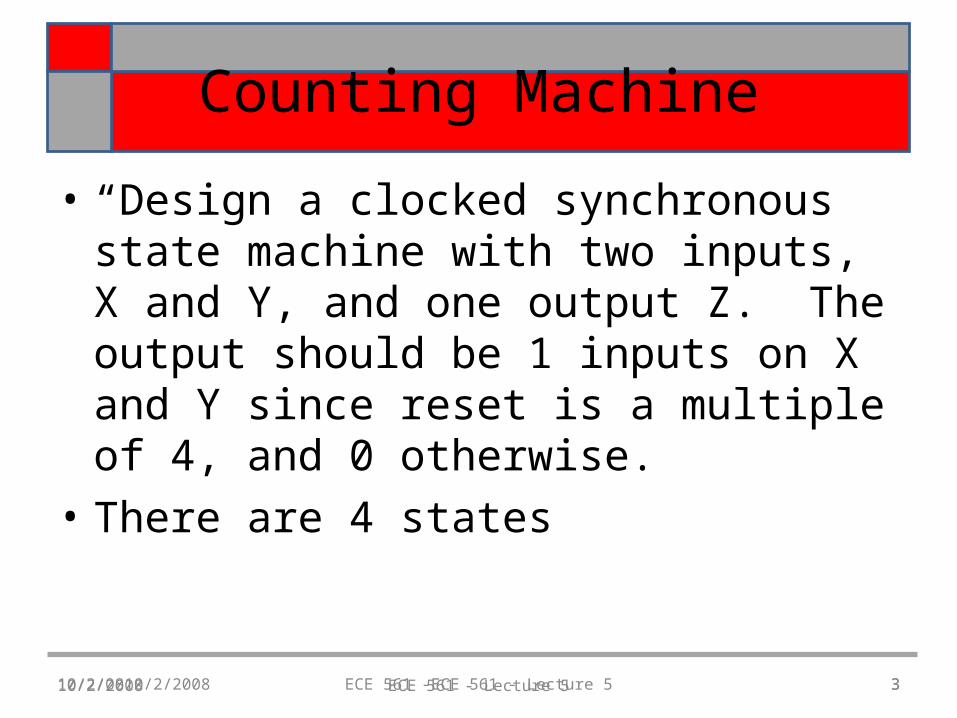
Counting Machine
• “Design a clocked synchronous state machine with two inputs, X and Y, and one output Z. The output should be 1 inputs on X and Y since reset is a multiple of 4, and 0 otherwise.
• There are 4 states
10/2/2008 3ECE 561 - Lecture 5
10/2/0810/2/2008 ECE 561 -ECE 561 - Lecture 5 4
Construct a state table
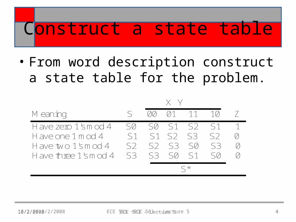
• From word description construct a state table for the problem.
10/2/2008 ECE 561 - Lecture 5 4
X Y
Meaning S 00 01 11 10 Z
Have zero 1's mod 4 S0 S0 S1 S2 S1 1Have one 1 mod 4 S1 S1 S2 S3 S2 0Have two 1's mod 4 S2 S2 S3 S0 S3 0Have three 1's mod 4 S3 S3 S0 S1 S0 0
S*
10/2/0810/2/2008 ECE 561 -ECE 561 - Lecture 5 5
Do a state assignment
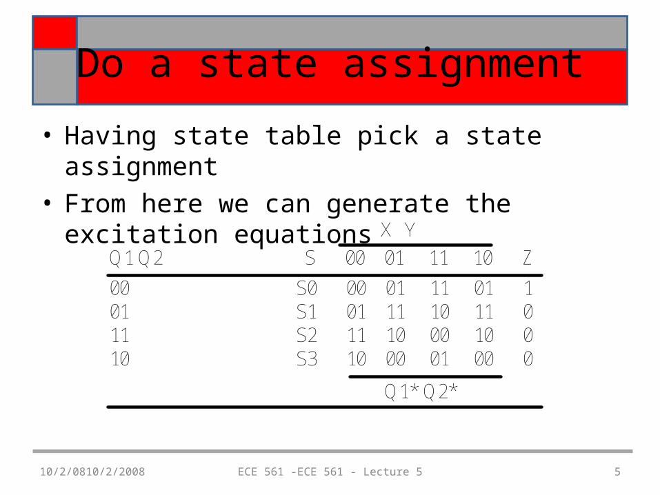
• Having state table pick a state assignment• From here we can generate the excitation equations
X Y
Q1 Q2 S 00 01 11 10 Z
00 S0 00 01 11 01 101 S1 01 11 10 11 011 S2 11 10 00 10 010 S3 10 00 01 00 0
Q1* Q2*
10/2/0810/2/2008 ECE 561 -ECE 561 - Lecture 5 6
Excitation Equations
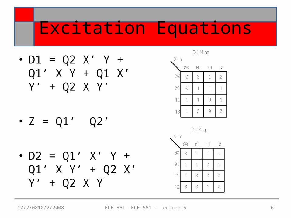
• D1 = Q2 X’ Y + Q1’ X Y + Q1 X’ Y’ + Q2 X Y’
• Z = Q1’ Q2’
• D2 = Q1’ X’ Y + Q1’ X Y’ + Q2 X’ Y’ + Q2 X Y
0 0 1 0
0 1 1 1
1 1 0 1
1 0 0 0
X Y
00 01 11 10
00
01
11
10
D1 Map
0 1 1 1
1 1 0 1
1 0 0 0
0 0 1 0
X Y
00 01 11 10
00
01
11
10
D2 Map
10/2/0810/2/2008 ECE 561 -ECE 561 - Lecture 5 7
Another Example
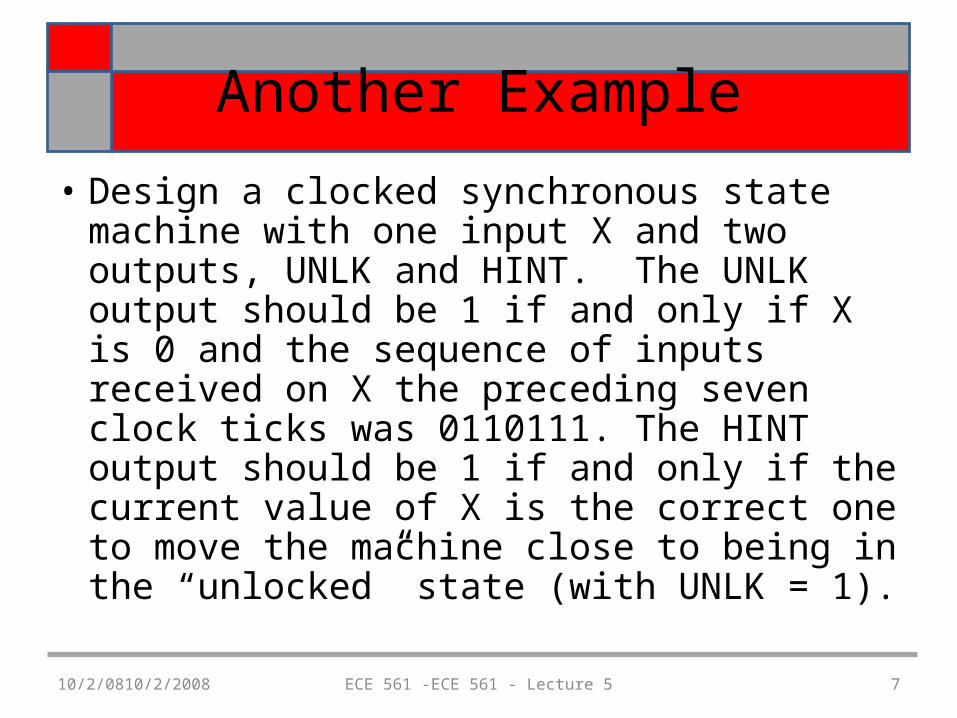
• Design a clocked synchronous state machine with one input X and two outputs, UNLK and HINT. The UNLK output should be 1 if and only if X is 0 and the sequence of inputs received on X the preceding seven clock ticks was 0110111. The HINT output should be 1 if and only if the current value of X is the correct one to move the machine close to being in the “unlocked” state (with UNLK = 1).
10/2/0810/2/2008 ECE 561 -ECE 561 - Lecture 5 8
Create State Table
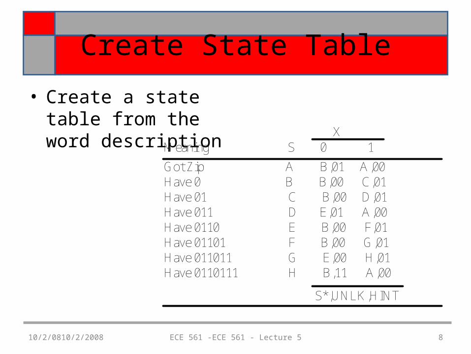
• Create a state table from the word description X
Meaning S 0 1
Got Zip A B,01 A,00Have 0 B B,00 C,01 Have 01 C B,00 D,01Have 011 D E,01 A,00Have 0110 E B,00 F,01Have 01101 F B,00 G,01Have 011011 G E,00 H,01Have 0110111 H B,11 A,00
S*,UNLK,HINT
10/2/0810/2/2008 ECE 561 -ECE 561 - Lecture 5 9
Choose a state assignment
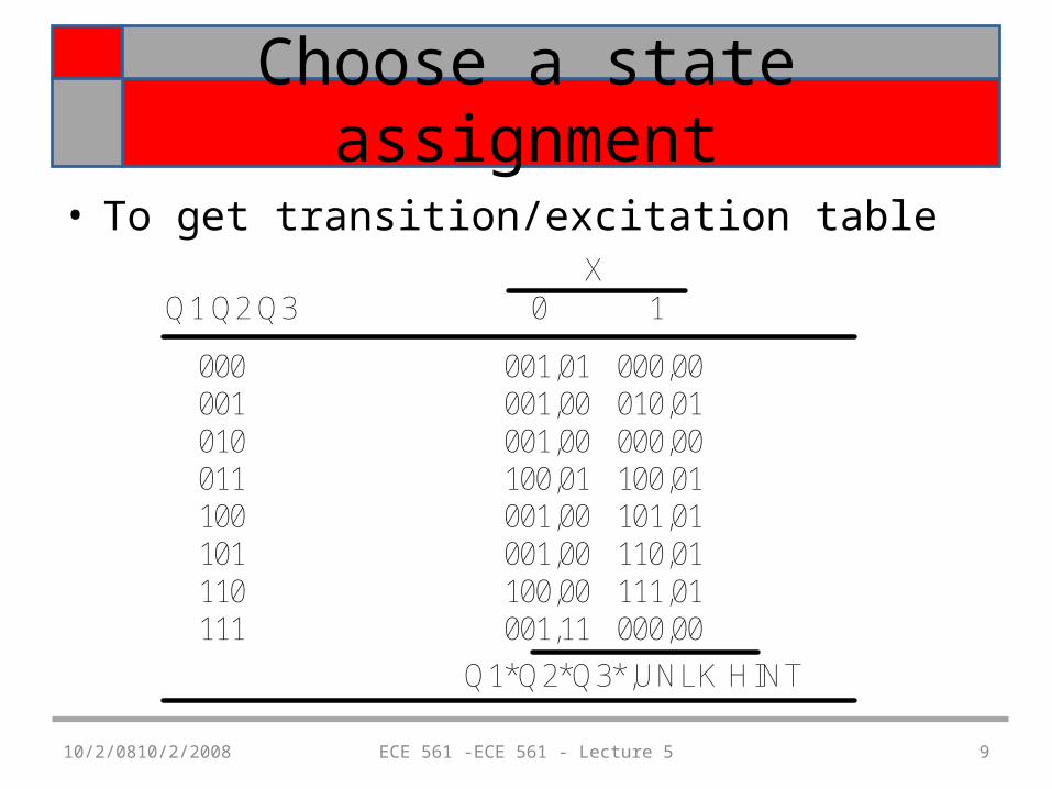
• To get transition/excitation tableX
Q1 Q2 Q3 0 1
Q1*Q2*Q3*,UNLK HINT
000001010011100101110111
001,01001,00001,00100,01001,00001,00100,00001,11
000,00010,01000,00100,01101,01110,01111,01000,00
10/2/0810/2/2008 ECE 561 -ECE 561 - Lecture 5 10
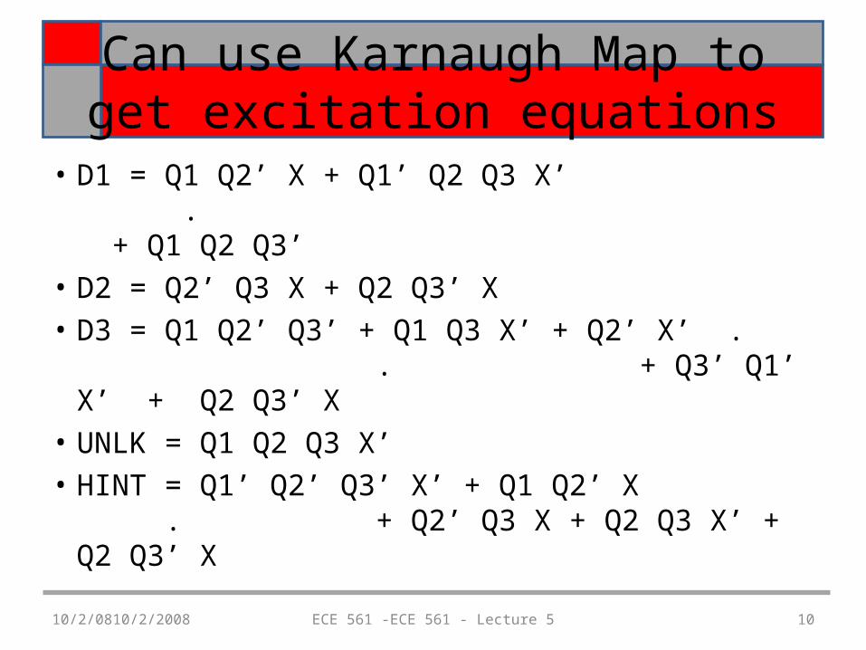
Can use Karnaugh Map to get excitation equations
• D1 = Q1 Q2’ X + Q1’ Q2 Q3 X’ . + Q1 Q2 Q3’
• D2 = Q2’ Q3 X + Q2 Q3’ X• D3 = Q1 Q2’ Q3’ + Q1 Q3 X’ + Q2’ X’ .
. + Q3’ Q1’ X’ + Q2 Q3’ X• UNLK = Q1 Q2 Q3 X’• HINT = Q1’ Q2’ Q3’ X’ + Q1 Q2’ X .
+ Q2’ Q3 X + Q2 Q3 X’ + Q2 Q3’ X
10/2/0810/2/2008 ECE 561 -ECE 561 - Lecture 5 11
For both examples
• Having the excitation and output equation can do the implementation in discrete logic or perform a schematic capture for FPGA tools such as XILINX or Altera.
10/2/0810/2/2008 ECE 561 -ECE 561 - Lecture 5 12
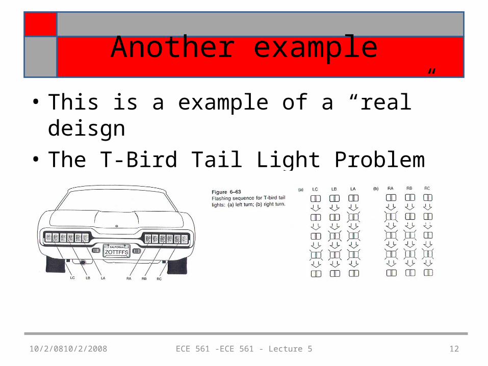
Another example
• This is a example of a “real” deisgn• The T-Bird Tail Light Problem
10/2/0810/2/2008 ECE 561 -ECE 561 - Lecture 5 13
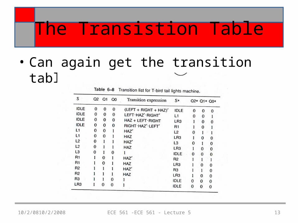
The Transistion Table
• Can again get the transition table
10/2/0810/2/2008 ECE 561 -ECE 561 - Lecture 5 14
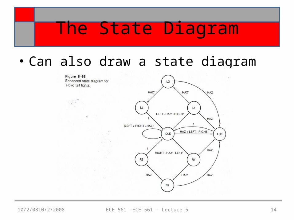
The State Diagram
• Can also draw a state diagram
10/2/0810/2/2008 ECE 561 -ECE 561 - Lecture 5 15
Final steps
• Choose F/F type• Choose a state assignment• Develop the transition/excitation table for
that state assignment• Generate the equations
10/2/0810/2/2008 ECE 561 -ECE 561 - Lecture 5 16
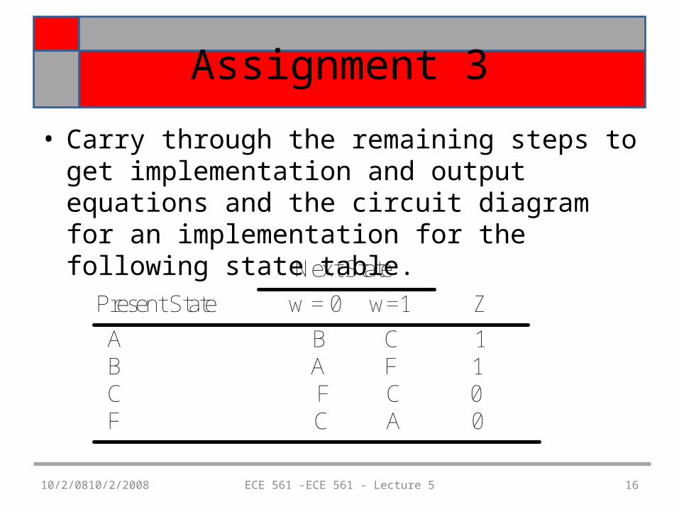
Assignment 3
• Carry through the remaining steps to get implementation and output equations and the circuit diagram for an implementation for the following state table.
Next State
Present State w = 0 w=1 Z
A B C 1 B A F 1 C F C 0 F C A 0