
1999: Application of Low invasion Coring and Outcrop … · Application of Low Invasion Coring and...
16
Application of Low Invasion Coring and Outcrop Studies to Reservoir Development Planning for the Villano Field J. J. Rathmell, ARCO Technology and Operations Services, Laura K. Atkins, ARCO Dubai, Inc., and James G. Kralik, ARCO Technology and Operations Services Copyright 1999, Society of Petroleum Engineers, Inc . This paper was prepared for presentation at the Sixth Latin American and Caribbean Petroleum Engineering Conference held 21 to 23 April, 1999, in Caracas, Venezuela. This paper was selected for presentation by an SPE Program Committee following review of information contained in an abstract submitted by the author(s). Contents of the paper, as presented, have not been reviewed by the Society of Petroleum Engineers and are subject to correction by the author(s). The material as presented does not necessarily reflect any position of the Society of Petroleum Engineers, its officers, or members. Papers presented at SPE meetings are subject to publication review by Editorial Committees of the Society of Petroleum Engineers. Permission to copy is restricted to an abstract of not more than 300 words. Illustrations may not be copied. The abstract should contain conspicuous acknowledgment of where and by whom the paper is presented. Write Librarian, SPE, P.O. Box 833836, Richardson, TX 75083-3836, USA Telex, 163245 SPEUT. Abstract Drilling and coring of a discovery well in the Hollin sand, Villano Field in 1992 was followed by low invasion coring in a confirmation well. A large discrepancy existed between water saturation derived from the capillary pressure and well logs in the discovery well. Low invasion coring and outcrop studies were implemented to provide the data to calculate oil-in-place and hydrocarbon reserves. The field is located in environmentally sensitive rain forest. Low invasion coring with water based mud was the only feasible method for obtaining connate water saturation from core. The bromide tracer of mud filtrate indicated low invasion (<10 % pv filtrate) was found in 86% of the horizontal core plugs. Core plugging and preservation were conducted in a facility established at the drilling base camp, 30 minutes by helicopter from the rig. These plugs were then shipped to the USA for analysis. Core water saturation was in good agreement with capillary pressure tests. The low invasion core data indicated salinity varied from 2600 ppm chloride at water-oil contact to 36,000 ppm chloride at the top of the Hollin reservoir. This salinity gradient and native-state, Archie saturation exponent yielded log-derived water saturation equal to the low invasion core values. Reservoir description would be critical to a development plan for the field, which would produce by aquifer influx. The size and distribution of sand bodies and shales was addressed by a detailed description of the core to determine the sedimentary sequence and quality of the productive intervals, and measurements from a Hollin sand outcrop located in the Andes Mountains to the northwest of the field. Geostatistical methods were used for shale mapping. An objective geological model based on cores and outcrop was used to assign sand permeability, porosity and water saturation. Numerical simulation with this description and the steady state relative permeability data provided an oil rate forecast and the Plan of Development for the field. Introduction The Villano Field is located in Block 10 in the southwestern Oriente Basin, Ecuador. The block is on the western edge of the Amazon rain forest, approximately 33 km from the eastern foothills of the Andes Mountains and about 185 km by air, southeast of Quito. In the 1950’s, the Villano 1 well was drilled near the crest of the structure. Drilling was stopped at 67 feet into the Main Hollin producing formation. Low oil gravity in the hydrocarbon shows apparently discouraged testing and further drilling at that time. ARCO, the current operator, acquired the block during a 1988 licensing round. In 1992, Villano 2 was drilled down-dip of Villano 1 into the Main Hollin. Villano 2 produced 19° API oil at a commercially attractive rate from the Main Hollin. Coring was conducted with water-based
Transcript of 1999: Application of Low invasion Coring and Outcrop … · Application of Low Invasion Coring and...

Application of Low Invasion Coring and Outcrop Studies toReservoir Development Planning for the Villano Field
J. J. Rathmell, ARCO Technology and Operations Services, Laura K. Atkins, ARCO Dubai, Inc., and JamesG. Kralik, ARCO Technology and Operations Services
Copyright 1999, Society of Petroleum Engineers, Inc.This paper was prepared for presentation at the Sixth Latin American and Caribbean Petroleum Engineering Conference held 21 to 23 April,1999, in Caracas, Venezuela.
This paper was selected for presentation by an SPE Program Committee following review of information contained in an abstract submittedby the author(s). Contents of the paper, as presented, have not been reviewed by the Society of Petroleum Engineers and are subject tocorrection by the author(s). The material as presented does not necessarily reflect any position of the Society of Petroleum Engineers, itsofficers, or members. Papers presented at SPE meetings are subject to publication review by Editorial Committees of the Society ofPetroleum Engineers. Permission to copy is restricted to an abstract of not more than 300 words. Illustrations may not be copied. Theabstract should contain conspicuous acknowledgment of where and by whom the paper is presented. Write Librarian, SPE, P.O. Box833836, Richardson, TX 75083-3836, USA Telex, 163245 SPEUT.
AbstractDrilling and coring of a discovery well in the Hollin sand, Villano Field in 1992 was followed by lowinvasion coring in a confirmation well. A large discrepancy existed between water saturation derived fromthe capillary pressure and well logs in the discovery well. Low invasion coring and outcrop studies wereimplemented to provide the data to calculate oil-in-place and hydrocarbon reserves.
The field is located in environmentally sensitive rain forest. Low invasion coring with water basedmud was the only feasible method for obtaining connate water saturation from core. The bromide tracer ofmud filtrate indicated low invasion (<10 % pv filtrate) was found in 86% of the horizontal core plugs. Coreplugging and preservation were conducted in a facility established at the drilling base camp, 30 minutes byhelicopter from the rig.
These plugs were then shipped to the USA for analysis. Core water saturation was in good agreementwith capillary pressure tests. The low invasion core data indicated salinity varied from 2600 ppm chloride atwater-oil contact to 36,000 ppm chloride at the top of the Hollin reservoir. This salinity gradient andnative-state, Archie saturation exponent yielded log-derived water saturation equal to the low invasion corevalues.
Reservoir description would be critical to a development plan for the field, which would produce byaquifer influx. The size and distribution of sand bodies and shales was addressed by a detailed descriptionof the core to determine the sedimentary sequence and quality of the productive intervals, andmeasurements from a Hollin sand outcrop located in the Andes Mountains to the northwest of the field.
Geostatistical methods were used for shale mapping. An objective geological model based on cores andoutcrop was used to assign sand permeability, porosity and water saturation. Numerical simulation with thisdescription and the steady state relative permeability data provided an oil rate forecast and the Plan ofDevelopment for the field.
IntroductionThe Villano Field is located in Block 10 in the southwestern Oriente Basin, Ecuador. The block is on thewestern edge of the Amazon rain forest, approximately 33 km from the eastern foothills of the AndesMountains and about 185 km by air, southeast of Quito. In the 1950’s, the Villano 1 well was drilled nearthe crest of the structure. Drilling was stopped at 67 feet into the Main Hollin producing formation. Lowoil gravity in the hydrocarbon shows apparently discouraged testing and further drilling at that time.ARCO, the current operator, acquired the block during a 1988 licensing round.
In 1992, Villano 2 was drilled down-dip of Villano 1 into the Main Hollin. Villano 2 produced 19°API oil at a commercially attractive rate from the Main Hollin. Coring was conducted with water-based

mud and Polycrystalline Diamond Compact (PDC), round profile core bits. Core recovery was only 47%because the core diameter was too small, apparently due to core bit and core barrel instability. The Villano2 core did not provide valid connate water saturation. Produced brine samples from the aquifer contained529 ppm total solids. Log-derived water saturation calculated using this brine and assumed Archieparameters gave average connate water saturation near 30%. This seemed high for clean, high-quality,sandstone with 200 feet of oil column with the water-oil density difference giving a gradient of 0.048psi/foot. Mercury injection tests showed the average connate water saturation was indeed lower, about 17%, with an expected transition zone of about 6 to 7 feet. The comparison between log and mercury injectionestimates of connate water saturation can be seen in Figure 1.
The Villano crude oil is very undersaturated with a bubble point pressure of 190 psi with a gas oil ratioof 21 scf/bbl while bottom hole pressure is 4882 psig. The crude oil has 21° API stock tank gravity with areservoir viscosity of 16.3 cp at 213° F bottom-hole temperature.
The Hollin sand is a crossbedded, quartzarenite sandstone (average 93.2% quartz) with porosity of 20%and permeability often greater than 1 Darcy. Pore space is primarily intergranular with a small percentageof secondary intragranular pores. The sandstones contain small amounts of authigenic kaolinite (average2.7% total clay: 92% kaolinite, 7% illite, 1% chlorite) as localized clumps of book-like crystals, whichappear to be formed by in-situ alteration of potassium feldspar. Quartz overgrowth cementation occurredearly and prevented more severe compaction. Grain size ranges from fine-grained to very coarse-grainedwith only a trace of detrital clay. The rock can be heterogeneous with thinly bedded coarse or fine-grainedsand laminae, which extend to the full diameter of the whole core. The Hollin sand has excellent quality.
The shale description was very important to depletion planning since it was expected that the reservoirwould be produced by bottom-water drive. Coning of water into the producing wells can be significantlydelayed by shale baffles. Unfortunately, incomplete recovery in the Villano 2 prevented reliable shaledescription from cores.
The need for reliable connate water saturation and shale description in the Hollin reservoir made itimperative to core a second well in the field to provide the data needed for depletion planning andcalculation of hydrocarbon reserves. The low invasion coring method with water based coring mud wouldbe used to provide water saturation data and the rock needed for lab tests to measure reservoir condition,water-oil relative permeability.1,2,3 Oil-based mud, while still preferred for evaluating connate watersaturation, was ruled out by the environmentally sensitive well location. This is one of ARCO’s mostcomplete examples of the value of low invasion coring using water-based mud for reservoir studies. It isalso ARCO’s first outside-the-USA application of low invasion coring. Protocols in the laboratory and atthe well site have been improved since 1994. Several of these improvements will be described.
As a supplement to the core data, a study of a known Hollin outcrop was planned in the Andes to thenorthwest of the field to obtain a better idea of the shale types present, as well as their lateral extent anddistribution. A shale map could then be provided by ARCO’s stochastic shale generator after suitableconditioning with data from the outcrop, cores and well logs.
Operations at Villano #3Coring Mud. Hole problems prevented the setting of the 9 5/8 inch diameter casing immediately above thecoring depth. The casing shoe depth was 9183 feet, almost 2,600 feet above the coring depth. This left theNapo shales open to the well bore and required a high mud weight with chemical shale inhibition so thatthe well bore remained open for coring. Coring was being conducted in sidetrack #2. Drilling and well boreproblems forced the abandonment of the earlier attempts. The original plan was to change the mud to abland coring fluid at core point. This plan was abandoned when casing was set at a shallower depth thanoriginally planned.

Coring Mud FormulationWater 0.85 bblCationic PHPA 1.0 ppbCationic Low M.W. Copolymer 4.0 ppbBiopolymer 0.75 ppbBiocide 0.50 ppbStarch, Modified 9.0 ppbCellulose fiber 12.0 ppbKCl 35.0 ppbPotassium bromide 0.30 ppbCalcium carbonate 30.0 ppbBarite as needed
Fluid PropertiesMud weight, lb/gal 10.8pH 8.8Solids Content, Vol. % 16Plastic Viscosity, cp 34Yield Point, lb/100ft^2 28Gels(10 sec/10 min), lb/100ft^2 8/12API fluid loss, cc 3.8HTHP (200�F, 500 psi), cc 8.8Potassium, ppm 30600Chloride, ppm 43000
The 10.8 lb/gal mud weight would produce a hydrostatic pressure in the mud, which was 1800 psiggreater than the formation. Fortunately, mud cake is compressible so the static fluid loss and spurt-losswere expected to be only about 25% greater than the values which would have been found at the lowerhydrostatic pressure and mud weight with casing set just above core depth. While not ideal for obtaining anative-state core, experience suggested that low invasion coring could be used to minimize the problemscaused by the non-ideal coring fluid.
When the coring depth was reached in the Upper Hollin, a mud centrifuge was used to decrease mudsolids so that the sized calcium carbonate, 5 to 10 microns, cellulose fiber, and 2 lb/bbl additional starchcould be added. Because of drill solids, barite and calcium carbonate, the total mud solids were 16% (vol.).This coring mud gave acceptable high-temperature, high-pressure, (HTHP) fluid-loss for low invasion. Thepotassium bromide tracer had been added earlier. Coring fluid samples were take at the beginning and endof each core from the suction pit. These were shipped with the core for tracer analysis.Coring, Core Processing. Seven, 4-inch diameter cores were cut with low invasion core bits and 60-footbarrels with 100% core recovery. Coring rate ranged from 10 to 100 feet/hr with an average of 45 ft/hr. Thelowest coring rate was at the start of each core. Total core length was 428 feet extending from the UpperHollin through the water-oil contact in the Main Hollin. The aluminum inner barrels were cut into 3-footlengths, sealed with rubber caps and steel hose clamps. The cores were then placed in wooden boxes andsent to the ARCO operations base about 30 minutes by helicopter from the drilling rig.
A commercial laboratory located in Bogota, Colombia imported the equipment and a cadre of 10technicians to provide core sawing, plugging and preservation in a building constructed by ARCO for theseoperations. A geologist, reservoir engineer and lab technician from ARCO supervised this operation. Coreplugs were cut from sawed lengths of whole core (3 inches for routine core analysis and 9 inches for specialcore analysis laboratory, SCAL, plugs) which were slabbed 1/4-3/4 to avoid moving filtrate by pluggingfluid invasion from the more invaded outer radii. Each plug was cut into the center of the slab face.Invaded outer radii were removed from the plug by trimming. Routine horizontal core plugs 1-inchdiameter by 2 inches long were cut every foot using refined oil as plugging fluid. Vertical routine core plugsthe same size were cut every 10 feet with refined oil. Special core analysis laboratory (SCAL) plugs 1.5inches diameter by 2 inches long were cut using 1000 ppm KCl brine as the plugging fluid. These plugswere cut 3 to 4 plugs side-by-side, from selected intervals containing the most uniform rock. The plugs were

preserved by placing them in glass bottles immersed in the plugging fluid. The plug containers were purgedwith nitrogen gas to remove as much oxygen as possible. The bottles were sealed and weighed to detectleakage while shipping. The whole core was preserved in Saran wrap, aluminum foil and CoreSeal.Packaging for shipping has been described in the literature and will not be repeated here4. Not a single coreplug was lost due to bottle breakage in shipping. Core processing times were 4 to 6 hours for 60 feet.
The storage of the SCAL plugs under brine was the most acceptable solution available in this remotelocation. Anaerobic crude and humidified nitrogen gas are alternate fluids frequently used for SCALplugging operations. These plugging fluids have the advantage that plug water saturation does not increaseand no extraneous fluid is added to the core, which could cause a change in wettability. The Villano crudehad too high viscosity at room temperature for use in cutting plugs and nitrogen was not considered for thisoperation. Humidified nitrogen gas is now the plugging fluid used for cutting both routine and SCAL plugs,but requires the use of a vacuum exhaust system to control the dust generated in this operation. The plugsare preserved in Saran wrap, aluminum foil, meltable plastic and Barax-aluminum foil heat-sealed laminatewhen nitrogen gas is used as the plugging fluid.
A commercial laboratory conducted routine analysis in the USA beginning about 10 days after coringwas complete. Water saturation was determined by the Dean Stark method. After extraction withchloroform and drying in a vacuum oven to constant weight, the plug pore volume and permeability weremeasured in an automated device using gas expansion and pressure transients, respectively, at 800 psi netconfining pressure. Every tenth plug was also measured at the estimated reservoir net confining pressure,4500psi. The routine horizontal plugs were then crushed and extracted. The chloride and bromide in thecore extract and in the mud filtrate was measured by ion chromatography.
Core Data for Villano 3Mud Filtrate Invasion. The core and mud filtrate bromide data were used to calculate filtrate concentrationin the Dean Stark water.2 Bromide background in the formation brine varied from near 80 in the upperHollin to about 3 ppm at water-oil contact. These are the minimum values observed and are similar to thosewhich would be estimated if the ratio of bromide to chloride were similar to seawater. Bromideconcentration in the mud decreased during coring from 1000 ppm to 700 ppm as the mud was diluted tocontrol viscosity. The background bromide in the connate water had no significant effect on the calculatedfiltrate. Figure 2 gives the calculated filtrate saturation. The average value for filtrate saturation in thehorizontal core plugs above the oil-water contact was 5.2% pv for those plugs with permeability exceeding10 md. If the background bromide is taken as zero then this value becomes 5.7% pv. Permeability to airand coring rate are also shown in Figure 2.
Connate water saturation is calculated by subtracting the filtrate saturation from the water saturationmeasured by the Dean Stark method. The chloride concentration is calculated from equation (1):
CcwCl =
CdsCl −FCmf
Cl
1− F (1)
CcwCl -Concentration of chloride in connate water, ppm
CdsCl -Concentration of chloride in Dean Stark water, ppm
CmfCl -Concentration of chloride in Mud Filtrate, ppm
F -Fraction of filtrate in Dean Stark water
These calculated values of connate water saturation and chloride concentration in the formation brineare given in Figure 3. The chloride concentration at the water-oil contact is 2600 ppm and at the top of theupper Hollin, 36,000 ppm. Apparently there is aquifer recharge from the Andes, where the Hollin outcrops.It appears the low salinity in the aquifer may be due to meteoric water from this recharge.
There is a trend in the chloride concentration with the amount of contamination by the mud filtrate.This is shown in Figure 4. The trend becomes more accentuated the lower the formation brine chloride.Both the bromide and chloride analyses were checked for analytical error by ARCO as possible causes ofthis variation. The values measured by the commercial laboratory were verified. The extrapolated values

have been used to generate Figure 5, which shows the variation in the chloride concentration with depth.Also included in that figure are measured chloride values for samples which had no evidence of filtratecontamination, i.e., zero bromide. They give similar values to those from extrapolation. An error functioncurve fits the data. Assuming the formation was filled with brine having 36,000 ppm chloride initially, thetime to generate the chloride concentration gradient observed is about 200,000 years for a diffusioncoefficient of 8 x 10⁻⁷ cm2/sec. This indicates the low salinity in the aquifer could be relatively recent, butdiffusion coefficients for the native state rock have not been measured so there is great uncertainty in thisestimate.
When filtrate invasion is high, usually greater than 10% pv, it is found that connate water valuesbegin to decline. This is caused in part by expulsion of the mixture of connate water and filtrate by thesolution-gas-drive mechanism as the core is lifted to the surface and gas comes out of solution in the oil.Miscible displacement of the connate water may also occur as the mud filtrate invades to high values offiltrate saturation. The loss of connate water can be seen in Figure 6. When the fraction of filtrate in theDean Stark water exceeds 0.5, or about 11.8% pv, the connate water saturation becomes lowered. For thisreason, when calibrating logs or calculating J-function relationships the connate water saturation is onlycalculated for plugs for which filtrate in the Dean Stark water is less than half. The usual cut-off is about10 % pv filtrate saturation, however, this will not hold for all rock and all values of connate water since itdepends on relative permeability and displaceable saturation of hydrocarbons. A plot such as that shown inFigure 6 usually determines the cut-off.
The J-function in Figure 7 was generated with about 80% of the data above the water-oil contact.These are the samples that have low invasion with filtrate saturation less than 10%. A comparison is madebetween the connate water saturation from the low invasion core and that which would be estimated fromthe mercury injection data. There is reasonable agreement between the two sets of data. Low invasion coreconnate water saturation for the best rock, higher on structure is near 5% pv.
Special Core AnalysisRelative Permeability. The SCAL plugs for relative permeability tests were cut and stored under anaerobicbrine in Ecuador. Screening permeability was then measured with anaerobic Villano crude (STO) atreservoir temperature, 215°F, and 500 psig, the normal procedure for low invasion core. These plugs werealso screened by CT scanning.
Two composites were formed from two sets of 5 plugs each. The data on the composites are given inTable 1, below. Composite 1 consisted of coarse-grained, high permeability sandstone plugs from Core 3(11,935.60 – 11,936.80’). Composite 2 consisted of medium-grained, intermediate permeability plugs fromCore 4 (11,972.45 – 11,985.95’). Four additional plugs were used to measure water-oil imbibition capillarypressure. These plugs encompassed the entire permeability to oil at initial water saturation, ko(Swi), range(400 to 1500 md) observed in the screening. In order to expedite the capillary pressure measurement, thespontaneous brine imbibition step was skipped. A fifth plug was placed in an Amott cell at 155°F. Afterone year, there was no discernible imbibition of brine. Imbibition of STO was also near zero. Apparentlythe rock is very weakly wet.
A synthetic brine was formulated based on an average invasion-corrected chloride concentration of11,650 ppm in the formation water for Cores 3 and 4. Calcium and potassium molar concentrations wereassumed to be 10% of that of sodium. The compatibility of this brine with the rock was tested by unsteady-state waterflood on one of the remaining plugs at 215°F and 500 psig. The pressure drop across this plugwas constant for 150 pv after oil production effectively ceased, indicating no rock-brine interactions.
Stock tank fluids were used for relative permeability testing because the oil in the reservoir isessentially dead. The filtered, dewatered, anaerobic crude was used in the waterfloods at 215°F. Due to thethermal limits of the centrifuge coreholder receivers, centrifuge displacements were conducted at 155°F. Aportion of the filtered, dewatered anaerobic crude was stabilized at 165°F for the centrifuge tests. Thecentrifuge measurements indicate that water-oil capillary pressure is minimal over a wide saturation range.Forced oil imbibition on the centrifuge at the highest speed used in the capillary pressure measurement(3200 rpm) resulted in water saturations between 0.06 and 0.10. These values are comparable to theconnate water saturations in the Core 3 rock. In the Core 4 rock, connate water saturation, Swc, was 0.22.

The composite core tests were conducted at 215°F and 500 psig. Prior to injection of water, a crude oiltracer test was performed to independently measure oil-filled pore volume. At the end of the imbibitioncycle, a brine tracer test was conducted to independently measure water-filled pore volume. If no furthertests were required, the composite was then extracted and its routine properties were measured.
An unsteady-state (USS) waterflood was conducted in Composite 1 at an injection rate of 60 cc/hr.After 28.8 PV of injection, the rate was bumped first to 180 cc/hr, then to 540 cc/hr. The rate was thendecreased in stages back to 60 cc/hr. Oil production continued during all but the last step, despite theinjection of an additional 335 PV of brine. Water injection rate was increase to 9 times the original rate andthen decreased back to the original rate. The relative permeability to brine increased from 0.2 to 0.7 in thisprocess. The saturations from the unsteady state waterflood are given in the table below. The resultingrelative permeability curves, which are rather unfavorable, are shown in Figure 8. The displacement wasdominated by viscous instabilities induced by the large oil to water viscosity ratio of 40. The weak capillarypressure forces ensured that relaxation of radial saturation gradients did not occur during the waterflood.These curves are of little value since the displacement violated the stability criteria that must be met tocalculate relative permeability from the production data. These results are a compelling reason forpreferring the steady-state method for acquiring valid oil-water relative permeability (krow-krw) curves forthis reservoir.
An immobile initial water saturation was reestablished in Composite 1 by recirculating anaerobic STOat 215°F and 450 psig through the composite until � P was constant and water production ceased inpreparation for a steady-state (SS) test. A tracer test in crude oil was used to measure oil-filled porevolume. After equilibrium was achieved on the final step (water fractional flow, fw, = 1), a tracer test wasconducted again for measurement of water-filled pore volume. The relative permeability curves are given inFigure 8. The steady-state measurement yielded lower water and higher oil relative permeability than didthe unsteady-state displacement. It should be noted that substantial volumes of brine were recirculatedthrough the composite at each fractional flow setting, with 600 PV displaced just in the final step (fw = 1).These large throughputs were necessary to establish saturation equilibrium at each water-oil ratio.
Table 1: Composite Test ResultsComp. Perms. Test PV L Swi Sor Inj. Sor(bump) Inj.(bump)
(md) cc cm (pv) (pv)1 1108-1282 USS 55.3 24.3 0.083 0.556 28.8 0.435 3351 1108-1282 SS 0.108 0.4152 493-615 SS 56.1 25.0 0.162 0.361 0.359
Precision of the saturation measurement by material balance is ±0.035 or better. Steady-state testingwas also conducted on Composite 2. After equilibrium at fw = 1, a rate bump (60 to 120 cc/hr) wasperformed which resulted in a very small reduction in oil saturation, in marked contrast to the bump afterthe unsteady-state displacement. The relative permeability to water was not significantly affected by thisprocedure. This change demonstrates that capillary pressure equilibrium had been established at the end ofthe fw = 1 step. The relative permeability curves, also shown in Figure 8, are more favorable than those ofComposite 1. Relative permeability to water, kw, for Composite 2 is lower than that for Composite 1 at anygiven Sw. The explanation is that the rock in Composite 2 is more homogeneous than that in Composite 1.
That contrast was visually evident when the plugs were first mounted. Thin layers of very coarse-grained sand extend through the core plugs. Further confirmation of the heterogeneity is provided by adispersion analysis of the tracer data. Much less dispersion occurred in both tracer tests performed onComposite 2 than on Composite 1. For the crude oil tracer test, the dispersion coefficients were 61 and 6cm2/hr for Composites 1 and 2, respectively. For the brine tracer tests, the corresponding values were 146and 40 cm2/hr. Despite the large throughput, the steady-state measurement did not reach low residual oilsaturation or low oil relative permeability.
In order to extend the range of the relative permeability curves and measure the ultimate waterfloodresidual oil saturation, Sorw, centrifuge relative permeability to oil in a waterflood, krow, measurements weremade on four additional plugs picked from the original set of 30 screened plugs. This is appropriate sincethe oil production in the field will involve gravity drainage of oil upward as the water flows in from theaquifer below. These plugs had ko(Swi) values ranging from 520 to 2150 md. The average Sorw was 0.187 ±

0.035, which is substantially lower than that achieved with displacement. Once Sorw was attained,permeability to water at residual oil saturation, kw(Sorw), was measured at 155°F and 500 psig. The resultingcentrifuge krow curves and kw(Sorw) endpoints extend the displacement results in a consistent fashion, asdemonstrated in Figure 8. The centrifuge and displacement data present an excellent example of how thesteady-state displacement and centrifuge measurements complement each other.Resistivity Measurements. Native-state resistivity core plugs (1.5 inches diameter by 2.0 inches long)were cut from the preserved whole core after the core arrived in the USA and about 2 months after coring.The plugging fluid was refined oil. The plugs were stored under plugging fluid until used for testing. Theresistance was measured in a constant temperature bath at 140° F.
A native-state resistivity was measured on the plug with its as-received water saturation and formationwater salinity. Water saturation was then measured using Dean Stark analysis, followed by cleaning withchloroform, extraction of salt with water, displacement with methanol, drying, pore volume measurementby gas expansion. The salinity of the formation brine was calculated from the Dean Stark water volume andby measuring the extracted salts. From this salt concentration, a value for brine resistivity was estimated.The plug was then resaturated with brine containing 178,000 ppm sodium chloride and 2700 ppm calciumchloride. Resistivity was measured after flow and equilibration with the brine at four different brinesalinities which showed clay conductivity was negligible. The formation resistivity factor from these testswas used to calculate the resistivity of the plug when 100% saturated with the formation brine found in theplug. The value of the Archie cementation exponent, m, was 1.74 with the constant, a = 1.
Restored-state resistivity was measured on a separate group of core plugs, in order to extend the rangeof water saturations. These were first extracted with chloroform-methanol azeotrope, dried, pore volumewas measured by gas expansion, and then the core plug was resaturated with the same initial brine as above.The procedure summarized above was used to evaluate Archie cementation exponent. The restored-stateplugs were then flooded with refined oil and resistivity index was determined. A plot of the Archiesaturation exponent, n, is given in Figure 9 for both the native-state and restored-state protocols. Theobserved variation of n with water saturation was built into the log interpretation model.5 While the samplesare not highly microporous, the microporosity that is present is highly correlated with the level of kaoliniteclay minerals. On the average, the pore space less than 2 microns comprises about 10 % of the pore spacebut varies from as little as 2 % to as much as 20% of total, based on mercury injection experiments.
It must also be stated that an oil drive for establishing water saturation in resistivity index testing is nolonger used because of saturation gradients remaining in the core plug. Porous plates with a nitrogen driveare now used to desaturate core plugs for resistivity index tests.
Mercury injection tests and x-ray diffraction data were measured after resistivity testing.
Comparison of Villano 3 Cores and Well LogsThe well log interpretation method described below was applied to the Villano 2 and Villano 3 wells. Theborehole-corrected total gamma-ray log was used to calculate clay volume with a clay value of 200 API anda sand value of 45 API. Porosity was calculated from the borehole corrected bulk density log (matrixdensity = 2.66 g/cc and fluid density = 1.0 g/cc) with correction for clay effects using the gamma-ray clayvolume and a clay porosity of 0.08. The laboratory measured value of m and n which were discussed abovehave been used in the Simandoux equation with the clay resistivity value, 3.0 ohm meters, obtained in theoverlying Napo shales. The Villano 3 chloride concentration varied from 36,000 ppm at the top of theHollin to 2600 ppm at the water-oil contact, according to the diffusion curve in Figure 5. Formation brineresistivity was then estimated from the equivalent sodium chloride concentration. The diffusion curve wastruncated at the top when the pay zone was not as thick as that found in Villano 3, so that salinity at the topof the pay zone declined as the pay thinned at the edges of the field. The salinity at the water-oil contactwas held constant. The variation of n with water saturation required an iterative solution. The startingvalue for n was taken as 2.0 and a value of water saturation was calculated. A new value of n was thenestimated from Figure 9 data and this was repeated until the difference between consecutive calculations ofwater saturation was less then 0.0015.
The comparison of the Villano 3 well log derived water saturation and low invasion cores are given inFigure 10. The agreement is excellent. The contrast between the log-derived water saturation in the twoFigures 1 and 10 should be noted. The water saturation varies from 5 to 6 % pv at 11834’ to about 20 % pv

just above the water-oil contact. The mean core water saturation is 9.96% pv and the mean log derivedwater saturation is 9.84% pv. It is estimated the standard deviation of water saturation from cores is about±4 % pv and about ±10 % pv for the well logs. The standard error of the mean will be (standarddeviation)/(number of feet) ^0.5. In the numerical model, capillary pressure curves giving the same watersaturation as the Villano 3 cores and logs was used to initialize the model.
Stratigraphy and Depositional EnvironmentAbout 5 km of Mesozoic and Cenozoic sediments are preserved in the Villano Field. The lower most unit isthe Lower Cretaceous Chapiza Formation, which consists of a thick series of continental redbeds andvolcanic deposits. Figure 11 shows a stratigraphic section for the Villano Field. This is overlain by fluvialquartz arenite sandstone of the Main Hollin formation, which is overlain by the shallow marinetransgressive clastics of the Upper Hollin. The Napo shale conformably overlies the Upper Hollin. TheVillano 3 core was described in detail to provide an understanding of the depositional environment withinthe Main Hollin. The lower part of the Main Hollin was deposited in incised valleys cut into the Chapizaformation, and consists of a thick series of braided stream deposits with excellent reservoir quality. The bulkof this unit is water bearing in the Villano Field. The upper part of the formation, which contains themajority of the oil in the Main Hollin, is interpreted to have been deposited in a sandy meandering riversystem. The point bars of the meandering river deposits are excellent quality sandstones, while thicker bedsof poorer quality are common in the upper part of the Main Hollin and are interpreted to be crevasse splay,levee and chute fill deposits.
Hollin Outcrop StudyA detailed study of three outcrop sections of the Hollin formation along the Loreto-Coca Road wasundertaken to obtain additional geologic data to develop a reservoir description to be used in a reservoirsimulator. The outcrop locations are about 50 kilometers northwest of the Villano Field in apaleodepostional basinward setting. Figure 12 is a montage showing sections at the measured locations andlog response.
The three outcrop locations are aligned east to west, with a distance of 0.5 kilometers betweenlocations 1 and 3, and 4 km between locations 1 and 2. At sections 1 and 3 the Main hollin formationoverlies the Chapiza unconformity and the Upper Hollin is present above the Main Hollin, which allowedthe placement of the various facies within the Main Hollin to be observed. At location 3 the contact withthe Napo shales was also observed, but the Chapiza was not.
The outcrop sections at each location were photographed, described in detail and sampled. A gammaray log was measured using a hand held scintillometer. Thin sections were cut from 75 samples to measureand understand mineralogy and log response for each facies. The outcrops were photographed and shaletype, size and distribution were measured.
The depositional environments in the outcrops have similar sedimentary structures and individual unitthickness as those observed in cores from the Villano Field. The Main Hollin in the outcrops consists ofbraided stream, point bar and transitional marine sands as in the Villano Field, although the overallthickness of each unit is less in the outcrop. Four primary types of impermeable barriers or baffles occur inthe outcrop and in the field; (1) bar tops or mud flats within the braided stream environment; (2) overbank,floodplain or levee silts and clays; (3) abandoned clay-filled channels within the point bar sands; and (4)clay drapes within the upper point bars. In the Villano Field, fine-grained restricted bay deposits arepresent in the Upper Hollin and chute filled deposits are present in the Main Hollin.
A stratigraphic model of the Main Hollin formations was developed using interpreted depositionalenvironments from core and wireline log data in the Villano and Moretecocha (a Hollin discovery, about 11miles south-southeast of Villano) Fields and from measured sections of the outcrop study. The objectivewas to derive a geologically sound model of the stratigraphic variation to be expected within the MainHollin formation. Based on the preserved thickness of up to 50 feet in the individual point bar deposits inthe field, the size of the meandering river system of the upper part of the Main Hollin formation is in thesame order of magnitude as the present day Mississippi River system in the United States. An arealphotograph of a representative portion of the Mississippi River system could then be used to estimate therelative frequency of occurrence of point bar deposits, overbank levee deposits, preserved floodplain

deposits, crevasse splays, chutes and abandoned channels or oxbow lake deposits. The less complex braidedstream of the lower part of the Main Hollin was modeled using standard published facies models for suchsystems. The resulting cross section was representative of the stratigraphic variation likely to occur in anyvertical slice though the field and was used as a basis for the reservoir simulator description.
Geostatistical Shale Mapping and Reservoir Simulator DescriptionShales in the Villano reservoir represent barriers or baffles to vertical flow, which will significantly impactoil recovery under the expected bottom-water drive mechanism. A realistic description of the shales wasnecessary to predict oil rate and recovery in the reservoir simulator, and confirm the economic viability ofthe proposed development scenario.
The shale body sizes and distribution determined from Villano cores, the outcrop study and thestratigraphic model were incorporated into ARCO’s Stochastic Shale Generator program, which generatesmultiple descriptions of the shales which honor the data.6 The program inputs include probabilitydistributions for the thickness, length, width and frequency of the various types of shales observed in theHollin depositional environments. The output includes transmissibility modifiers for each grid-block thatare directly read into the reservoir simulator.
Ten types of shales with widely varying dimensions were defined to describe the shales occurring in thethree main depositional environments of the Hollin formation; (1) marine/transition, (2) meandering river,and (3) braided stream. The shale dimensions were defined using triangular probability distributionfunctions that account for the minimum, most likely, and maximum values of each dimension. Figure 13shows a sample of a triangular distribution function for floodplain shales. A wide variation in shale typesand sizes was necessary to develop a description consistent with the geological model.
In addition to the size, the frequency of occurrence of the shales was incorporated into the model, usingvolume fractions of each type of shale by model layer, which were determined by the depositional faciespresent in the layer. A volume fraction of zero for any shale indicated that shale was not present in thatlayer. For shales that were present, the volume fraction is defined as the volume of shale type in the layerdivided by the total volume of reservoir in the layer. Only size and volume of shale was used in thisstochastic model; no orientation was specified. The shale model was conditioned using the shales observedin the Villano 2 and Villano 3 cores.
The stochastic shale generator calculates the effective vertical transmissibility for each simulatorgridblock, which allows the effect of the shales on vertical flow to be modeled. The permeability factorsrange from zero to one, so that when no shales are present in a gridblock, the permeability factor is one. Agridblock partially covered by shales will have a permeability factor between zero and one depending on thesize of the shales and their position within the block, while a gridblock completely covered by a shale willhave a permeability factor of zero. Since the stochastic shale generator provides multiple descriptions thathonor the data, the most likely description was chosen as the one that most closely resembled thestratigraphic cross section developed by the geologists. The shale description as it appeared in the simulatoris shown in Figure 14. This figure shows all the shales on the left side and only the larger shales on theright side.
Reservoir Simulation and Predicted PerformanceThe reservoir description and laboratory data were incorporated into ARCO’s reservoir simulator to predictperformance of the field under different development scenarios. The original oil in place was calculatedusing a structure map derived from seismic data, with rock properties and fluid saturations determinedwireline logs tuned to the core data. The 3-D reservoir model was built using ARCO’s reservoir simulator.The model contains 21,528 gridblocks, with 23 vertical layers, which are 10’ thick in the oil column tomodel coning behavior. The areal grid is of varying size, with the minimum cell size of 600’ x 300’ overthe expected producing area of the field. Porosity and permeability were obtained from core data. Watersaturation was then calculated from the well logs calibrated with the core data. Fluid properties wereavailable from PVT data measured on bottom-hole samples and relative permeability came from steady-statemeasurements on Villano 3 low invasion composite cores as described earlier.
There were two key inputs to the reservoir model that had a large impact on the predicted fieldperformance, the shale description and the relative permeability data. Due to time constraints, the unsteady

state relative permeability data, which takes less time to measure, were tried in the simulator. These curveswere highly unfavorable and inaccurate, due to viscous effects described earlier, and resulted in a reserveprediction for the field that was uneconomic. It was then decided to defer the study until the steady-statedata were available. The first few data points from the first steady-state composite, supplemented by data athigh water saturations from another ARCO field with similar fluid properties and wetting characteristics,provided sufficient data to develop a relative permeability curve for the simulation. This curve was laterconfirmed after the steady state measurements were completed. The data from composite 2 wereincorporated into the model later, resulting in a higher final rate prediction on which the currentdevelopment plan is based.
The reservoir simulator showed that depending on the nature and placement of the shales, the modelpredicted that the wells could produce under either bottom water or edge water drive, or both, depending onthe well’s proximity to one of the larger shales. Because of the uncertainty in the actual shale description,either mechanism is possible at any point in the reservoir. Early production of water in the up-dip wells isas likely as it is for the down-dip wells. Therefore, it was recognized that the well plan needed to be flexiblein order to adapt to the water influx pattern, indicating that high angle wells with the capability to producefrom multiple zones would be needed.
Current Status of Field DevelopmentThe Villano Field is currently under development and is expected to start up in mid-1999. The well plancalls for recompleting wells Villano 2 and 3, and drilling five high angle wells to produce a plateau rate of40,000 STBD. Produced water will be disposed of in a well completed in the aquifer. The field will bedeveloped without the use of roads, with all equipment to be brought in by helicoptor. The high angle wellswill be drilled from a single well pad to minimize the amount of space required in this sensitive rain forestenvironment.
The integrated study using the Villano 3 core data and the description efforts, including the outcropstudy were key to the development plan for this field. The discovery of the water salinity gradient and thevariable saturation exponent provided a basis for determining water saturation from wireline logs. Therelative permeability data and shale description had a large impact on the predicted oil and waterproduction. The potential edge water drive mechanism indicated the need to be able to complete the wellswithin multiple intervals to produce oil located between large shale bodies, resulting in the decision to drillhigh angle rather than strictly horizontal wells. Although there is still uncertainty in the water productionpredictions, the results from this study provided a sound basis for facility design and confirmed theeconomic viability of the field.
Conclusions1. Salinity varied from the top to the bottom of the reservoir. Coring is the only method to obtain such
information.2. Water-based mud low invasion coring yields reliable connate water saturation and improved agreement
between core data, logs and mercury injection data.3. Unsteady state waterflood gave a poor estimate of water-oil relative permeability due to viscous
fingering and core plug scale heterogeneity.4. The steady state method of relative permeability measurement leads to prediction of higher oil recovery
in high mobility ratio waterflood5. Centrifuge and steady state measurement methods give similar curves for relative permeability.6. Outcrop studies were essential to prediction of edge-water and bottom-water drive performance.7. The engineering study and plan of development for the Villano Field could not have been reliably
completed without the carefully designed and executed coring and data acquisition plan.
AcknowledgmentsThe authors thank ARCO Oriente, Inc., AGIP Petroleum (Ecuador) and Petroecuador for permission topublish these results. The contents and conclusions in this paper are those of the authoring company andmay not be shared by the other working interest owners. We acknowledge the contributions of Hughes-Christensen for the coring bits, Baker Hughes INTEQ for field operational support, Core Lab, Bogota and

Dallas for the core handling, preservation and analysis and the ARCO drilling staff. We thank thenumerous people in ARCO Oriente, Inc., ARCO Exploration and Production Technology and ARCOInternational Oil and Gas Company who made significant contributions to the success of this project.
References1. Rathmell, J. J., Tibbitts, G. A., Gremley, R. B., Warner, H. R. Jr., and White, E. K., "Development of a Method for
Partially Uninvaded Coring in High Permeability Sandstones," SPE 20413 presented at the SPE Annual TechnicalConference and Exhibition in New Orleans, La., 23-26 September, 1990, SPE Formation Evaluation, June 1995,65-71.
2. Rathmell, J. J., Gremley, R. B. and Tibbitts, G. A., "Field Applications of Low Invasion Coring," SPE 27045,Presented at LACPEC III, Buenos Aires, Argentina, 27-29 April, 1994.
3. Rathmell, J. J., Gale, B. A., Tibbitts, G. A., Bobrosky, D. J., Wilton, B. S. and Bell, D. A., “Development andApplication of PDC Core Bits for Down-hole Motor Low Invasion Coring in the Arab Carbonates”, SPE 36263presented at the 7th ADIPEC held in Abu Dhabi, 13-16 October, 1996, SPEDC, March 1998.
4. Rathmell, J. J., Bloys, J. B., Bulling, T.P., Parr, J. J., Pasternack, E. S., Jerauld, G. R., and Sakurai, S., “LowInvasion, Synthetic Oil-Base Mud Coring in the Yacheng 13-1 Gas Reservoir for Gas-in-Place Calculation” SPE29985 Presented at the 1995 International Meeting on Petroleum Engineering held in Beijing, China, 14-17November, 1995.
5. Worthington, P. F. and Pallatt, N., “Effect of Variable Saturation Exponent upon the Evaluation of HydrocarbonSaturation”, SPE 20538, Presented at the SPE Annual Technical Conference in New Orleans, La., 23-26,September, 1990.
6. Perez, G., Chopra, A. K. and Severson, C. D. “Integrated Geostatistics for Modeling Fluid Contacts and Shales inPrudhoe Bay,” paper SPE 26475, presented at the Society of Petroleum Engineers Annual Technical Conference andExhibition, Houston, Texas, 3-6 October, 1993.

Figure 1: Villano 2 logs give high Sw comparedto mercury injection.
Figure 3: Connate water saturation andformation brine chloride after adjustment for
invasion by mud filtrate.
Figure 2: Villano 3 core properties, coring
rate and invasion
0.1
1
10
100
1000
10000
11800 11900 12000 12100Core Depth (feet)
PermeabilityCoring RateFiltrate Saturation
1
10
100
1000
10000
100000
11800 11900 12000 12100Core Depth (feet)
Chloride in ScwSat. Con. Water, Scw
0
10
20
30
40
50
0.000 0.100 0.200 0.300 0.400 0.500Fraction Filtrate in Dean Stark Water
11811' to 11837'
11903' to 11929'
11950' to 11982'

Figure 4: Variation in filtrate adjustedformation brine chloride with level of mudfiltrate invasion.
Figure 5: Variation in formation brine chloridewith depth
Figure 7: J-Function from the Villano 3 lowinvasion core connate water saturationcompared tomercury injection.
Figure 6: Loss of connate water by solution-gas-drive during lifting.
Figure 8: Reservoir condition water-oil relativepermeability from the Villano 3 composites.
0
5
10
15
20
25
30
35
40
11600 11800 12000 12200 12400Core Depth (feet)
Lowest InvasionExtrapolationRegression
0
10
20
30
40
50
0 0.2 0.4 0.6 0.8 1Fraction Filtrate in Dean Stark Water
11840' to 11999'K > 500 md
Loss of connate water
No significant trend
0.1
1
10
0 20 40 60 80 100Water Saturation (% pv)
Scw CoreØ=18.7%, K=893mdØ=18.5%, K=891mdØ=22.1%, K=1140mdØ=19.1%, K=725mdØ=18.3%, K=1500mdØ=20.8%, K=901md
0.00001
0.0001
0.001
0.01
0.1
1
0 0.2 0.4 0.6 0.8 1
Water Saturation
Rel
ativ
e P
erm
eab
ility
UnsteadyState Steady-State
Centrifuge k row
Endpointk rw (S orw )
Composite 1
Composite 2

Figure 9: Archie saturation exponentmeasured by native-state and restored-statemethods on the Villano 3 core plugs.
Figure 10: Water saturation from Villano 3well logs and cores
Figure 11: Stratigraphic Section of the Villano Field
0.0
0.5
1.0
1.5
2.0
2.5
3.0
3.5
4.0
0 0.2 0.4 0.6 0.8 1
Water Saturation
Native StateRestored State

Figure 12: Cross section of Hollin outcrop showing shale type and distribution with gamma ray log response
Figure 13: Distribution functions for floodplain shale dimensions in geostatistical shale generator
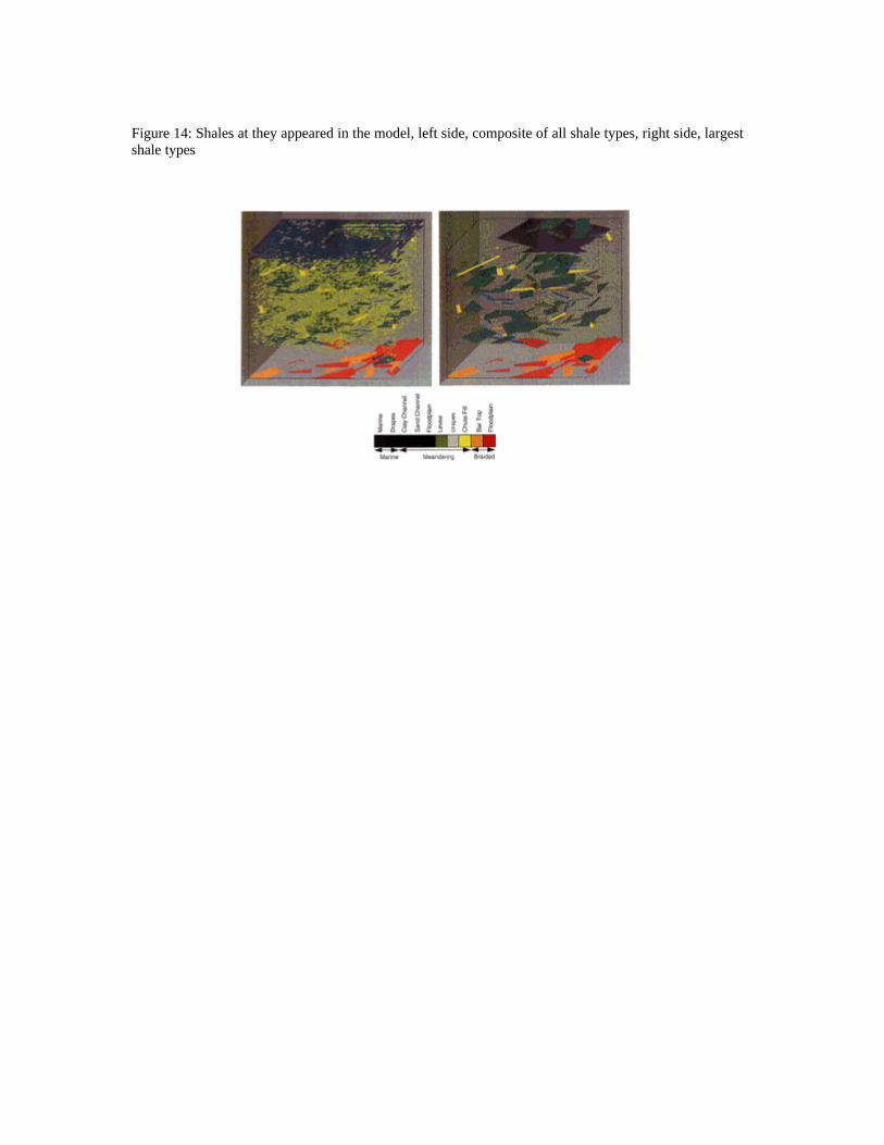
Figure 14: Shales at they appeared in the model, left side, composite of all shale types, right side, largestshale types