19160 Install Guide
21
R I NSTALLATION G UIDE A DAPTEC SCSI CA R D 19160
-
Upload
johnwoo12345 -
Category
Documents
-
view
219 -
download
0
Transcript of 19160 Install Guide
8/8/2019 19160 Install Guide
http://slidepdf.com/reader/full/19160-install-guide 1/20

8/8/2019 19160 Install Guide
http://slidepdf.com/reader/full/19160-install-guide 2/20

8/8/2019 19160 Install Guide
http://slidepdf.com/reader/full/19160-install-guide 3/20
1
Adaptec SCSI Card 19160
The Adaptec SCSI Card 19160 Ultra160 SCSI controller enables
you to connect up to 15 SCSI devices—such as hard disk drives,
scanners, and CD-ROM drives—to any Intel-based computer
with 32-bit PCI expansion slots.
You can connect newer LVD SCSI devices, such as Ultra160 and
Ultra2 SCSI devices, to the 68-pin internal Low Voltage
Differential/Single-Ended (LVD/SE) connector. You can also
connect Single-Ended (SE) Fast/Ultra SCSI devices, to the 50-pin
internal and external Fast/Ultra-SE connectors.
This installation guide explains how to
• Install the Adaptec SCSI Card 19160
• Set up SCSI devices
• Connect SCSI devices
INTRODUCTION
50-pin External Fast/Ultra-SE Connector
68-pin Internal LVD/SE Connector50-pin Internal Fast/Ultra-SE Connector
8/8/2019 19160 Install Guide
http://slidepdf.com/reader/full/19160-install-guide 4/20
2
Installation Guide
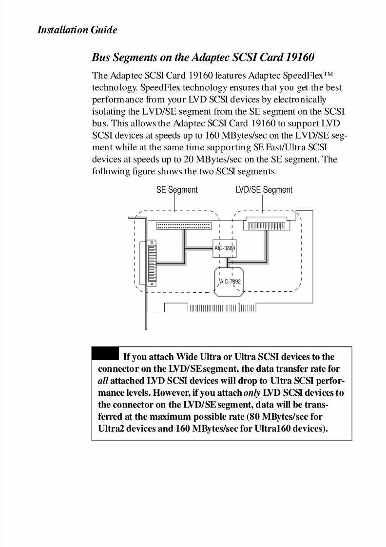
Bus Segments on the Adaptec SCSI Card 19160
The Adaptec SCSI Card 19160 features Adaptec SpeedFlex™
technology. SpeedFlex technology ensures that you get the best
performance from your LVD SCSI devices by electronically
isolating the LVD/SE segment from the SE segment on the SCSI
bus. This allows the Adaptec SCSI Card 19160 to support LVD
SCSI devices at speeds up to 160 MBytes/sec on the LVD/SE seg-
ment while at the same time supporting SE Fast/Ultra SCSI
devices at speeds up to 20 MBytes/sec on the SE segment. The
following figure shows the two SCSI segments.
If you attach Wide Ultra or Ultra SCSI devices to the
connector on the LVD/SE segment, the data transfer rate for
all attached LVD SCSI devices will drop to Ultra SCSI perfor-mance levels. However, if you attach only LVD SCSI devices to
the connector on the LVD/SE segment, data will be trans-
ferred at the maximum possible rate (80 MBytes/sec for
Ultra2 devices and 160 MBytes/sec for Ultra160 devices).
AIC-3860
AIC-7892
SE Segment LVD/SE Segment
NOTE

8/8/2019 19160 Install Guide
http://slidepdf.com/reader/full/19160-install-guide 5/20
3
Adaptec SCSI Card 19160
Discharge any static electricity build-up before handling the SCSI
card by touching a grounded metal object (like the exposed metal
parts on the back of your computer).
After you turn off your computer and unplug the power cord,
remove the cover from the computer.
Locate an unused 32-bit PCI expansion slot and remove the
expansion slot cover. (The expansion slot must be compliant
with PCI Rev. 2.1 or higher and must support Bus Mastering.)
Save the slot cover screw for use in Step 4.
INSTALLING THE ADAPTEC SCSI CARD 19160
STEP 1
Turn OFF power to the computer and disconnect
the power cord.
WARNING
STEP 2
STEP 3
Slot Cover Screw
Expansion
Slot Cover
PCI Expansion Slots
(Typically White or Ivory)
8/8/2019 19160 Install Guide
http://slidepdf.com/reader/full/19160-install-guide 6/20
4
Installation Guide
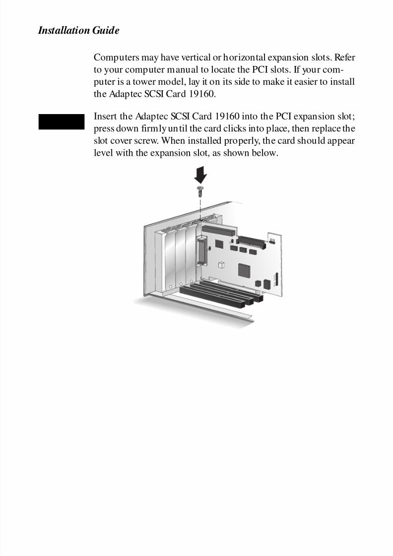
Computers may have vertical or horizontal expansion slots. Refer
to your computer manual to locate the PCI slots. If your com-
puter is a tower model, lay it on its side to make it easier to install
the Adaptec SCSI Card 19160.
Insert the Adaptec SCSI Card 19160 into the PCI expansion slot;
press down firmly until the card clicks into place, then replace the
slot cover screw. When installed properly, the card should appear
level with the expansion slot, as shown below.
STEP 4
8/8/2019 19160 Install Guide
http://slidepdf.com/reader/full/19160-install-guide 7/20
5
Adaptec SCSI Card 19160
There are several things you may need to do to your SCSI devices
before you connect them to the Adaptec SCSI Card 19160:
• Check the SCSI IDs
• Terminate the Ends
• Mount the Devices
Since setup can vary from device to device, always refer to the
device’s documentation for specific instructions.
Below are some guidelines for checking SCSI IDs, setting termi-
nation, and mounting devices in your computer. Refer to the
Adaptec SCSI Card 19160 User’s Reference for more information
on these topics.
Check the SCSI IDs
The Adaptec SCSI Card 19160 and each device you connect to it
must have a unique SCSI ID number ranging from 0 to 15.
No two devices can have the same number.
The Adaptec SCSI Card 19160 is preset to SCSI ID 7 and should
not be changed. If your computer will boot from a SCSI hard
disk, make sure the SCSI ID of that hard disk is set to 0. (Most
SCSI hard disks are preset to SCSI ID 0 at the factory.)
The SCSI IDs for internal devices are usually set with jumpers;
SCSI IDs for external devices are usually set with a switch on the
back of the device.
Terminate the Ends of the SCSI Bus
To ensure reliable communication on the SCSI bus, the device at
the end of each cable, or the end of the cable itself, must have a
terminator installed (or enabled). Terminators must be removed,
or termination must be disabled, on devices between the ends of
each cable.
Terminating LVD (Ultra160 and Ultra2) SCSI Devices
LVD SCSI devices are automatically un-terminated. If you have
internal LVD SCSI devices, a special 68-pin internal LVD cable is
required to connect the devices. Internal LVD cables usually have
SETTING UP SCSI DEVICES
8/8/2019 19160 Install Guide
http://slidepdf.com/reader/full/19160-install-guide 8/20
6
Installation Guide
an LVD or Auto switching terminator built into the end of cable.
With this type of cable, it is not necessary to terminate individual
internal LVD SCSI devices. If your cable does not have a termina-
tor built-in, you must add a terminator to the end of the cable.
Terminating Fast/Ultra SCSI Devices
On most internal Fast/Ultra SCSI devices, the termination setting
is controlled by setting a jumper or a switch, or by physically
removing or installing a resistor module(s). If you are using an
internal SCSI cable that has a built-in terminator, you must dis-
able termination on all internal devices connected to the cable.
On most external Fast/Ultra SCSI devices, termination is con-
trolled by installing or removing a terminating plug. For more
information, refer to the documentation for each SCSI device.
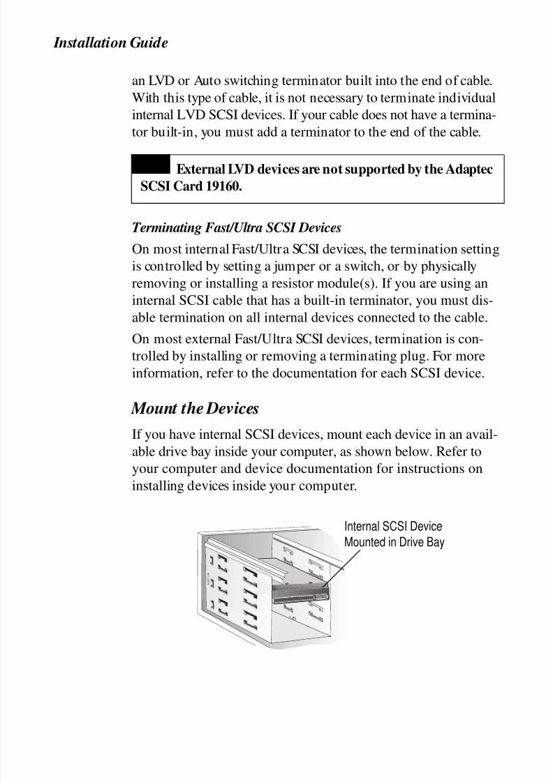
Mount the DevicesIf you have internal SCSI devices, mount each device in an avail-
able drive bay inside your computer, as shown below. Refer to
your computer and device documentation for instructions on
installing devices inside your computer.
External LVD devices are not supported by the Adaptec
SCSI Card 19160.
NOTE
Internal SCSI Device
Mounted in Drive Bay
8/8/2019 19160 Install Guide
http://slidepdf.com/reader/full/19160-install-guide 9/20
7
Adaptec SCSI Card 19160
You can connect up to 15 SCSI devices to the Adaptec SCSI Card
19160. Before connecting devices, be sure to review Setting Up
SCSI Devices on page 5. For additional details on connecting
devices, refer to the Adaptec SCSI Card 19160 User’s Reference.
Connecting Internal LVD (Ultra160 and Ultra2) SCSI
Devices
Connect internal LVD SCSI devices to the internal LVD/SE
connector on the Adaptec SCSI Card 19160. To do this, use a68-pin internal LVD cable like the one shown in Step 1 below.
Follow these steps to connect the devices:
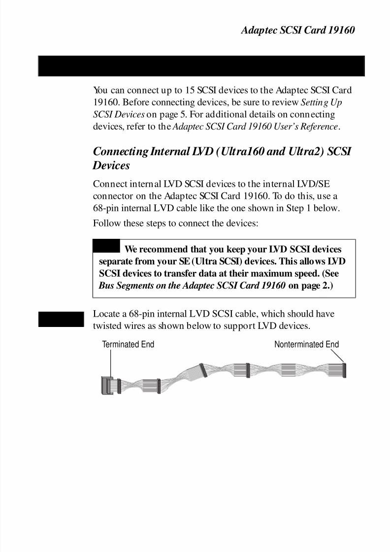
Locate a 68-pin internal LVD SCSI cable, which should have
twisted wires as shown below to support LVD devices.
CONNECTING SCSI DEVICES
We recommend that you keep your LVD SCSI devices
separate from your SE (Ultra SCSI) devices. This allows LVD
SCSI devices to transfer data at their maximum speed. (See
Bus Segments on the Adaptec SCSI Card 19160 on page 2.)
NOTE
STEP 1
Terminated End Nonterminated End
8/8/2019 19160 Install Guide
http://slidepdf.com/reader/full/19160-install-guide 10/20
8
Installation Guide
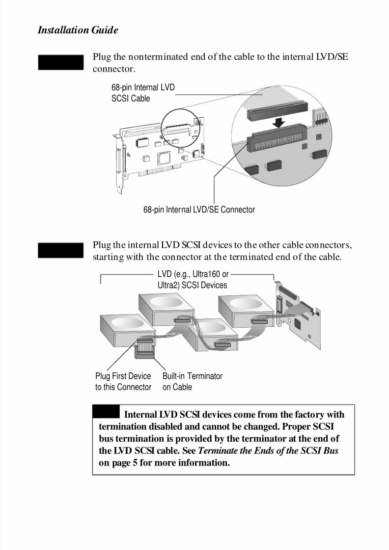
Plug the nonterminated end of the cable to the internal LVD/SE
connector.
Plug the internal LVD SCSI devices to the other cable connectors,
starting with the connector at the terminated end of the cable.
STEP 2
68-pin Internal LVD
SCSI Cable
68-pin Internal LVD/SE Connector
STEP 3
Internal LVD SCSI devices come from the factory with
termination disabled and cannot be changed. Proper SCSI
bus termination is provided by the terminator at the end of
the LVD SCSI cable. See Terminate the Ends of the SCSI Bus
on page 5 for more information.
LVD (e.g., Ultra160 or
Ultra2) SCSI Devices
Built-in Terminator
on Cable
Plug First Device
to this Connector
NOTE

8/8/2019 19160 Install Guide
http://slidepdf.com/reader/full/19160-install-guide 11/20
9
Adaptec SCSI Card 19160
Connect a power cable from your computer’s internal power sup-
ply to each internal SCSI device.
Connecting Internal Fast/Ultra SCSI Devices
Connect internal Fast/Ultra SCSI devices that have standard
50-pin connectors to the 50-pin internal Fast/Ultra-SE SCSI con-
nector. To do this, use a 50-pin internal Ultra Narrow SCSI cable.
Follow these steps to connect the devices:
Locate a 50-pin internal Ultra Narrow SCSI cable.
STEP 4
Power Input Connector onthe Back of the Device
Power Cable (From the PowerSupply Inside the Computer)
STEP 1
8/8/2019 19160 Install Guide
http://slidepdf.com/reader/full/19160-install-guide 12/20
10
Installation Guide
J
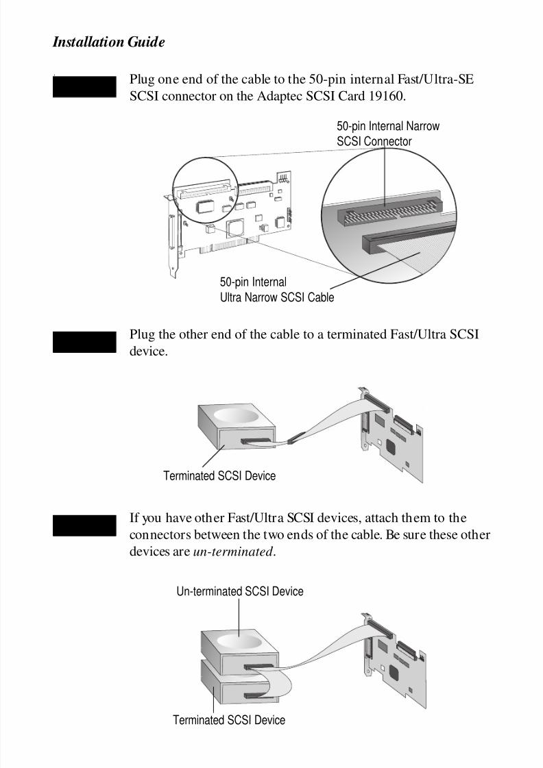
Plug one end of the cable to the 50-pin internal Fast/Ultra-SE
SCSI connector on the Adaptec SCSI Card 19160.
Plug the other end of the cable to a terminated Fast/Ultra SCSI
device.
If you have other Fast/Ultra SCSI devices, attach them to the
connectors between the two ends of the cable. Be sure these otherdevices are un-terminated .
STEP 2
50-pin Internal
Ultra Narrow SCSI Cable
50-pin Internal Narrow
SCSI Connector
STEP 3
Terminated SCSI Device
STEP 4
Un-terminated SCSI Device
Terminated SCSI Device

8/8/2019 19160 Install Guide
http://slidepdf.com/reader/full/19160-install-guide 13/20
11
Adaptec SCSI Card 19160
Connect a power cable from your computer’s internal power
supply to each internal device.
Connecting External Fast/Ultra SCSI Devices
Connect external Fast/Ultra SCSI devices that have 50-pin
connectors to the 50-pin High-density external Fast/Ultra-SE
connector. Each external device will require a 50-pin
High-density external SCSI cable. Follow these steps to connect
the external devices:
Connect one end of the external SCSI cable to the 50-pin external
Fast/Ultra-SE connector on the Adaptec SCSI Card 19160.
STEP 5
Power Input Connector onthe Back of the Device
Power Cable (From the PowerSupply Inside the Computer)
STEP 1
50-pin ExternalFemale SCSI
Connector50-pin High-density
External SCSI Cable

8/8/2019 19160 Install Guide
http://slidepdf.com/reader/full/19160-install-guide 14/20
12
Installation Guide
Connect the other end of the external SCSI cable to a SCSI
connector on the back of an external SCSI device.
If you are installing only one external device, terminate the device
and skip to Step 4.
Connect other external devices by cabling each device to the pre-
vious one, as shown below. Terminate only the device at the end
of the chain.
Connect power cables to all external devices and to the computer.
STEP 2
4
4
SCSI Terminator
STEP 3
Terminated
Un-terminated
STEP 4

8/8/2019 19160 Install Guide
http://slidepdf.com/reader/full/19160-install-guide 15/20
13
Adaptec SCSI Card 19160
To use the Adaptec SCSI Card 19160, the card’s driver softwaremust be installed for your operating system (for example,
Windows®98, Windows NT®, etc.). The Ultra160 Family
Manager Set contains driver software for many of the popular
operating systems.
Refer to the Ultra160 Family Manager Set User’s Guide and
Adaptec SCSI Card 19160 User’s Reference for instructions on
either installing driver software when installing your operating
system, or installing driver software when the operating system is
already installed.
If you have any problems while installing the Adaptec SCSI Card
19160, check the following items first:
• Are all SCSI devices powered on?
• Are all SCSI cables and power cables properly connected?
• Does each device on the SCSI bus have a unique SCSI ID?
• Does the total SCSI cable length exceed the maximum allow-
able length? (See the Adaptec SCSI Card 19160 User’s
Reference for more information.)
• Is the SCSI bus properly terminated?
If you are still unable to resolve a problem, refer to the Adaptec
SCSI Card 19160 User’s Reference, or the Adaptec Web site athttp://www.adaptec.com for additional troubleshooting
information.
ADAPTEC SCSI CARD DRIVER SOFTWARE
Operating system versions released after November,
1999, may have embedded driver support for the Adaptec SCSI
Card 19160. To determine if the card is supported by the oper-
ating system you are using, read the operating system manual
or contact the operating system vendor for information.
NOTE
TROUBLESHOOTING

8/8/2019 19160 Install Guide
http://slidepdf.com/reader/full/19160-install-guide 16/20
8/8/2019 19160 Install Guide
http://slidepdf.com/reader/full/19160-install-guide 17/20
15
Copyright
© 1999 Adaptec, Inc. All rights reserved. No part of this publication may be reproduced, stored in a
retrieval system, or transmitted in any form or by any means, electronic, mechanical, photocopy-
ing, recording or otherwise, without the prior written consent of Adaptec, Inc., 691 South Milpitas
Blvd., Milpitas, CA 95035.
TrademarksAdaptec, the Adaptec logo, and SpeedFlex are registered trademarks of Adaptec, Inc., which may be
registered in some jurisdictions. Windows, Windows 98, and Windows NT are registered trade-
marks of Microsoft Corporation in the U.S. and other countries used under license.
All other trademarks are owned by their respective owners.
Changes
The material in this document is for information only and is subject to change without notice.
While reasonable efforts have been made in the preparation of this document to assure its accu-
racy, Adaptec, Inc. assumes no liability resulting from errors or omissions in this document, or
from the use of the information contained herein.
Adaptec reserves the right to make changes in the product design without reservation and without
notification to its users.
Disclaimer
IF THIS PRODUCT DIRECTS YOU TO COPY MATERIALS, YOU MUST HAVE PERMISSION
FROM THE COPYRIGHT OWNER OF THE MATERIALS TO AVOID VIOLATING THE LAW
WHICH COULD RESULT IN DAMAGES OR OTHER REMEDIES.
Regulatory Compliance Statements
Federal Communications Commission Radio Frequency Interference Statement
WARNING: Changes or modifications to this unit not expressly approved by the party responsible for compli-
ance could void the user’s authority to operate the equipment.
This equipment has been tested and found to comply with the limits for a Class B digital device, pursuant to Part
15 of the FCC rules. These limits are designed to provide reasonable protection against harmful interference in a
residential installation. This equipment generates, uses, and can radiate radio frequency energy, and if not
installed and used in accordance with the instruction manual, may cause harmful interference to radio commu-
nications. However, there is no guarantee that interference will not occur in a particular installation. However, if
this equipment does cause interference to radio or television equipment reception, which can be determined by
turning the equipment off and on, the user is encouraged to try to correct the interference by one or more of thefollowing measures:
• Reorient or relocate the receiving antenna.
• Increase the separation between equipment and receiver.
• Connect the equipment to an outlet on a circuit different from that to which the receiver is connected.
• Consult the dealer or an experienced radio/television technician for help.
• Use a shielded and properly grounded I/O cable and power cable to ensure compliance of this unit to the spec-
ified limits of the rules.

8/8/2019 19160 Install Guide
http://slidepdf.com/reader/full/19160-install-guide 18/20
16
This device complies with par t 15 of the FCC rules. Operation is subject to the following two conditions: (1) this
device may not cause harmful interference and (2) this device must accept any interference received, including
interference that may cause undesired operation.
European Union Compliance Statement
This Information Technology Equipment has been tested and found to comply with the following
European directives:
EMC Directive 89/336/EEC
EN 50081-1 (1992):EN55022 (1994) Class B
EN 50082-1 (1992):
EN61000-4-2 (1998)
EN61000-4-3 (1998)
EN61000-4-4 (1995)
Australian/New Zealand Compliance Statement
This device has been tested and found to comply with the limits for a Class B digital device, pursuant
to the Australian/New Zealand standard AS/NZS 3548 set out by the Spectrum Management Agency.
Canadian Compliance StatementThis Class B digital apparatus meets all requirements of the Canadian Interference-Causing Equip-
ment Regulations.
Cet appareil numérique de la classe B respecte tou tes les exigences du Règlement sur le matérial
brouilleur du Canada.
Japanese Compliance
Adaptec, Inc. Adaptec SCSI Card 19160
Tested to ComplyWith FCC Standards
FOR HOME OR OFFICE USE

8/8/2019 19160 Install Guide
http://slidepdf.com/reader/full/19160-install-guide 19/20

8/8/2019 19160 Install Guide
http://slidepdf.com/reader/full/19160-install-guide 20/20
© 1999 Adaptec, Inc. All rights reserved.Printed in Singapore
Stock No.: 512507-03, Rev. A RQ 12/99(SRC: 512507-00, Ver. AA)
R
We move the information that
moves your world.™