Printrboard Install Guide
12
-
Upload
copyingcat -
Category
Documents
-
view
153 -
download
0
description
Printrboard Rev E Install Guide
Transcript of Printrboard Install Guide


PrintrBoard Connections
Endstops: Gather the 3 endstops and endstop holders (only one of each is shown below)
Insert the Switch into the endstop Holder, depending on the printer the switch may be installed the opposite direction compared to the photo below.
PrintrBoard Connections—Continued
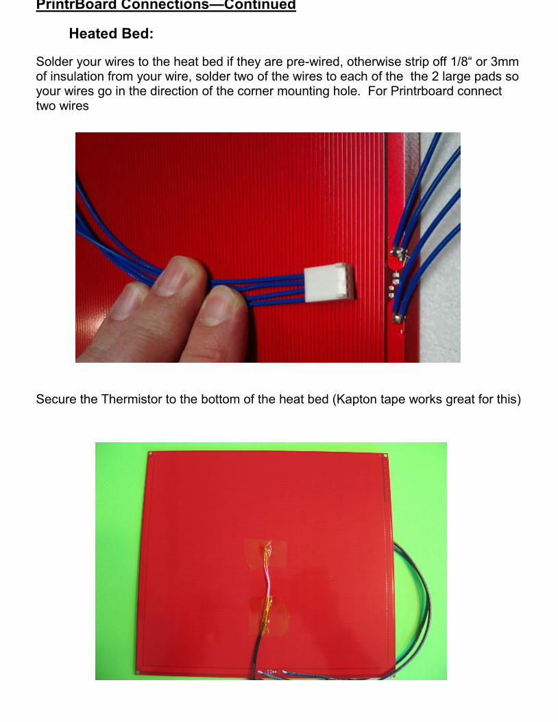
Heated Bed:
Solder your wires to the heat bed if they are pre-wired, otherwise strip off 1/8“ or 3mm of insulation from your wire, solder two of the wires to each of the the 2 large pads so your wires go in the direction of the corner mounting hole. For Printrboard connect two wires
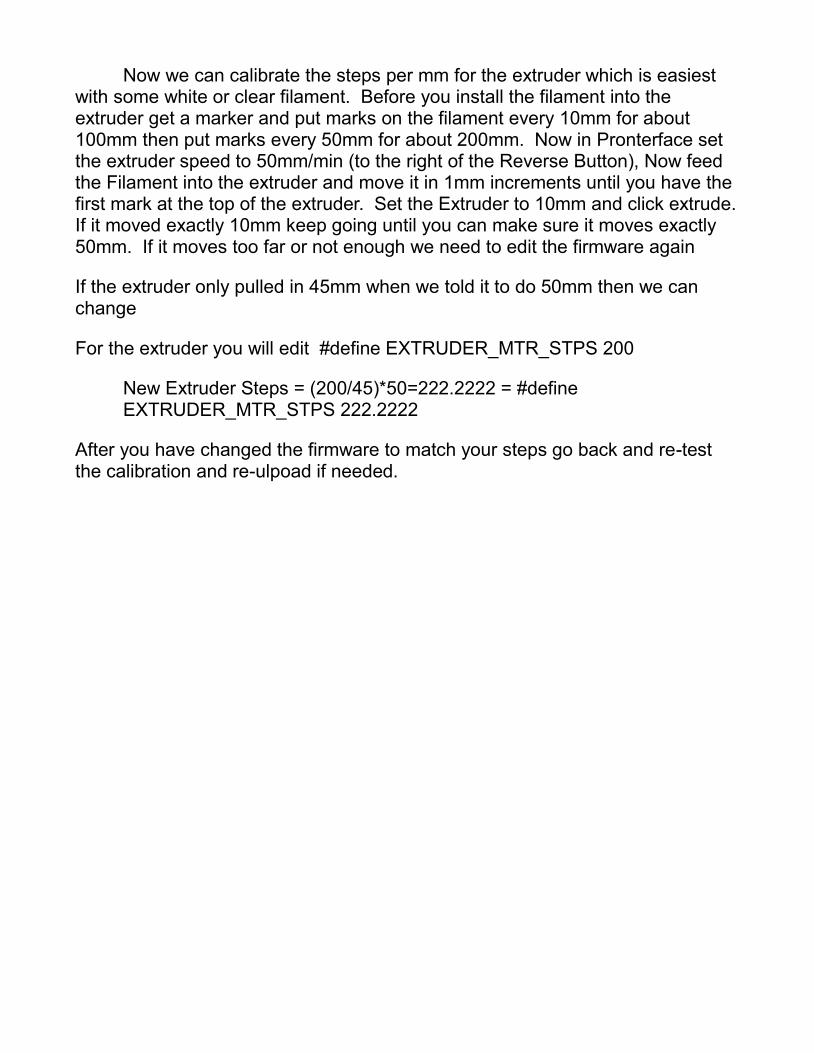
Secure the Thermistor to the bottom of the heat bed (Kapton tape works great for this)

PrintrBoard Connections—Continued
Power Connector: Use a standard ATX Power supply to power the Printrboard.

PrintrBoard Connections—Continued
Final Connections: Connect everything as seen below:

Firmware—CDC Bootloader
If your printrboard is Rev D and looks like the picture below use these instructions to upload firmware to your Printrboard:
The Printrboard come pre-loaded with the Marlin Firmware, but you may need or want to make changes. To load firmware follow the instructions below:
Run the file CDC Bootloader Drivers, then open the folder named Arduino0022 Printrboard, if you already have Arduino loaded on your PC or have a newer or older version make sure to use the one in the Zip file you downloaded. Other versions won„t work even if it is v22. Run the program arduino. If you are prompted to upgrade the arduino software to a newer version don„t do it.
Unlike older AVR microcontrollers, the AT90USB has a special HWB_ALU pin (Hardware Button) which must be tied to
ground during a reset cycle in order to place the microcontroller into bootloader mode. This is accomplished by installing a
jumper on the Printrboard Pins called "BOOT" or JP14. Firmware can only be loaded while the chip has booted into its
bootloader:
1. Install the BOOT jumper.
2. Press and release the Reset button. The AT90USB's bootloader may appear as a new USB device the first time you
boot into the bootloader. Allow Windows to install the USB driver and note the new COM port number.
3. Remove the BOOT jumper from the board.
4. In Arduino 022, open firmware (lincomatic-Marlin-MakerFarm\Marlin_Prusa\Marlin_Prusa.pde) (for Printrbot use
Marlin_6x6LCPB, for I3 use Marlin_i3)
5. Choose [BootloaderCDC]Teensylu/Printrboard from the Arduino Tools-->Board menu, and select the COM port
associated with your Printrboard's bootloader. (This com por is
different then the one used in pronterface)
6. Click File --> Upload to Board.
7. Arduino will compile and upload firmware. You should see an
error a few seconds after the firmware compiles. This is
because the AT90USB has successfully exited the bootloader.
8. Press Reset. You may need to disconnect and reconnect the USB and power cables.

Firmware—DFU Bootloader
If your printrboard is Rev D and looks like the picture below use these instructions to upload firmware to your Printrboard:
The Printrboard come pre-loaded with the Marlin Firmware, but you may need or want to make changes. To load firmware follow the instructions below:
Run the Program Flip Installer—3.4.7.112
Unlike older AVR microcontrollers, the AT90USB has a special HWB_ALU pin (Hardware Button) which must be tied to ground during a reset cycle in order to place the microcontroller into bootloader mode. This is accomplished by rinstalling a jumper on the Printrboard called "BOOT". Firmware can only be loaded while the chip has booted into its bootloader:
1. Install a the BOOT jumper or very carefully connect the two leads together with something metal.
2. Press and release the Reset button. The AT90USB's bootloader will appear as a new USB device the first time you
boot into the bootloader. Allow Windows to install the USB driver, if windows can‟t find the driver point it to the folder
“DFU Bootloader Drivers”
3. Remove the BOOT jumper onto the board.
DFU BOOTLOADER
1. Open Atmel's FLIP software (There should be an icon on your desktop from running the Flip Installer earlier)
2. Select the target device: AT90USB1286. Select Communication medium as USB. Click Open.
3. In Arduino 022, open firmware (lincomatic-Marlin-MakerFarm\Marlin_Prusa\Marlin_Prusa.pde) (for Printrbot use Marlin_6x6LCPB, for I3 use Marlin_i3)
4. Choose [BootloaderCDC]Teensylu/Printrboard from the Arduino Tools-->Board menu
4. Compile firmware within Arduino. You will need to copy and paste the compiled .HEX file into the HID application directory. The HEX file is saved in the temp folder,
Windows 7: C:\users\{currentuser}\appdata\local\temp\build1234567890\Firmware_Name_Here.cpp.hex
Windows XP: C:\Documents and Settings\{currentuser}Local Settings\Temp\build1234567890
\Firmware_Name_Here.cpp.hex
1. Open compiled HEX file within the FLIP software.
2. Make sure the Erase, Blank Check, Program, and Verify checkboxes are checked.
3. Click the Run button
4. When finished, disconnect and reconnect the USB and power cables, the push the reset button on the Printrboard.

Pronterface Install
Download Pronterface here.
Run Pronterface.
Select the port your Printrboard was installed to and set the baud to 250000 then click connect. You should get a message that say„s „Printer is now online“. If you don„t get this message and your screen just says „Connecting...“ for a long time follow the steps below.
1. Close Pronterface, unplug the USB Cable from the Printrboard, Shut off the Power to the Printrboard, Make sure the Y endstop is plugged into the port labeled E-Stop not Y-Stop.
2. Turn on the Power to the Printrboard, Plug in the USB Cable, Start Pronterface and click connect.
Basic Calibration Now get out your ruler and click x+10 in pronterface, see if the X axis moves 10mm, if it does proceed to Y, then Z axis (Make sure the Z Speed is set to 50mm/min in Pronterface, it„s just above the Z+ Arrow). Let say as an example that x & y move 8mm and Z moves 12mm.
Next you can open arduino, and open the marlin.pde firmware then goto the configuration.h tab, you will find the following lines (numbers will be different)
#define XY_MTR_STPS 260
#define Z_MTR_STPS 200
Using the measurements we made we can figure out the new steps:
X & Y Axis (260/8)*10= 325— #define XY_MTR_STPS 325
Z Axis (200/12)*10=166.6667— #define Z_MTR_STPS 166.6667
Now Reupload the firmware and test using +100 for all your axis to fine tune then use the same formula‟s (*100 in stead of *10) and upload again.
Note: For Z edit #define Z_ROD_PITCH, Change to 1.25 for 8mm Z Threaded Rods and 1.411111111111111 for 5/16” Z Threaded Rods.
Now we can calibrate the steps per mm for the extruder which is easiest with some white or clear filament. Before you install the filament into the extruder get a marker and put marks on the filament every 10mm for about 100mm then put marks every 50mm for about 200mm. Now in Pronterface set the extruder speed to 50mm/min (to the right of the Reverse Button), Now feed the Filament into the extruder and move it in 1mm increments until you have the first mark at the top of the extruder. Set the Extruder to 10mm and click extrude. If it moved exactly 10mm keep going until you can make sure it moves exactly 50mm. If it moves too far or not enough we need to edit the firmware again
If the extruder only pulled in 45mm when we told it to do 50mm then we can change
For the extruder you will edit #define EXTRUDER_MTR_STPS 200
New Extruder Steps = (200/45)*50=222.2222 = #define EXTRUDER_MTR_STPS 222.2222
After you have changed the firmware to match your steps go back and re-test the calibration and re-ulpoad if needed.

Slic3r
To generate the Gcode for our printer we are going to use Slic3r, Download Slic3r here, Slic3r saves it settings in a file called config.ini. First
we need to create this file by opening Slic3r then click Help and Configuration Wizard.
The Firmware type will be RepRap (Marlin/Sprinter)
Bed Size is 200x200 for V2 Prusa or 8x8 Printrbot or 150x150 for the 6x6 printrbot
Nozzle diameter will be either .35mm or .50mm (refer to your original order)
Filament Diameter will be 3mm
Extrusion Temperature will be 210c for ABS or 160c for PLA (Do not go above 225c)
Bed Temperature for Printrboard will usually be around 80c to 95c for ABS and 60c for PLA.
After you have completed the wizard click File and Export Config (Remember where you save this file so we can tell pronterface where it is)
1. Open Pronterface and go to Settings then Options Menu.
2. You will be modifying the slicecommand and sliceoptscommand options to replace - - load config.ini with - - load /full/path/to/your/INI_file. For Example, on Windows it might be something like: C:\Documents\Slic3r.ini
3. Close the Options Window
Slicing
Now that we have Slic3r setup in pronterface click Load File and find the Hollow Cube.stl in the Zip File. Slic3r will now slice the .stl file and get it ready to print.
Printing
Connect to your printer, click the Monitor Printer box at the top of the screen and click Print. Make sure your Z Endstop is about 5 or 10mm above the print bed and click print. Once we can see that stuff is working you can click pause, remove the printed platic an move the Z Endstop down a little then try again by Restart, You want to keep doing this until your printer puts down a good line of plastic that sticks to your printbed (a heated bed is recommended). If you go down to much you can damage your nozzle so be patient.
Happy Printing!
Troubleshooting:
1. Min Temp Error: if you are getting a Min Temp error then either your thermistor isn„t connected or one of the wires for the thermistor isn„t connected properly
2. Max Temp Error: If you are getting the Max Temp error check to make sure the thermistor leads or crimping ferrules aren„t touching each other, also make sure the thermistor leads aren„t grounding out on the Brass Nozzle.
3. The Hobbed Bolt is chewing up my filament: This problem is usually linked to trying to run the extruder to fast, but can also be linked to either to much heat or not enough heat in the hot end.
Heat: For ABS filament set the temperature to 225c and for PLA the temp should be inbetween 160c and 195c. Make sure you don„t set the temperature above 230c.
Speed: Open pronterface and make sure you set the speed (to the right of the Reverse button) to 50mm/min. Next in pronterface click settings, then slicing settings. In the Printer and Filament tab set all the speeds to 30 or less for a .35mm nozzle and 60 or less for a .50mm nozzle.
4. Endstop switchs only operate when you press the Home button in Pronterface, if you are jogging the motors in pronterface the home switches will not be used.
5. My Z motors dont work properly or one of them isn„t turning: This is usually caused by a speed setting in pronterface. Right under the Pause button there is a number, change it to 150 then exit and re-open pronterface making sure the 150 is still there.
6. After I click Print my printer doesn„t do anything: Once you click Print you should see numbers scrolling on the right hand side of your screen, that is your printer waiting before the correct temperatures have been reached before your printer starts printing.
7. As soon as I click Print my printers temps start to change: The temperatures on the main screen of pronterface only control the initial temperatures, as soon as you click print the Gcode takes over, to check your temperature settings first click on Settings, then Slicing Settings. In the Printer and Filament tab make sure the 4 temperatures in the bottom left of the screen are the temperatures you want to print with, if they are correct then next look in the G-code tab. If you see something in the Start Gcode box that says M104 S225 then that will set your hot end to 225c, if you see another line that says M190 S85, that is setting your heat bed temp, you can either remove these lines completely or change them to what you want your temps to be.

Troubleshooting:
8. My Heat Bed won„t heat above 80c: If you are in a cool room or if there is air blowing on your heat bed it can be difficult to get the heat bed much hotter then 80c. You can actually run your heat bed at 80c with ABS and get perfect prints. RAMPS and Gen6 both require the hot bed to be at around 110c for ABS, but somehow Printrboard works great at lower temperatures. If you do want to get your heat bed hotter you can Install a relay powered by the heat bed connection on the printrboard that will connect the heat bed directly to a 12v power source.
9.