WF007008(Slides)WF- HLR Subscriber Management -20070815-B-1.0.ppt

Title: The fire resistance performance of a specimen of single-acting single-leaf doorset in accordance with BS EN 1634-1: 2000 Report No: 163712 A
Prepared for: Novoferm GmbH Haldern Isselburger Str. 31 46459 Rees (Haldern) Germany Date: 13th August 2007 Notified Body No: 0833
0249

WF Test Report No. 163712 A
Page 2 of 33
Summary Objective To determine the fire resistance performance of two single-acting, single-leaf steel
based doorsets mounted within a high density rigid supporting construction, in accordance with BS EN 1634-1: 2000.
Test Sponsor Novoferm GmbH Haldern. Isselburger Str. 31, 46459 Rees (Haldern) Germany
Summary Of Tested Specimens
For the purpose of the test the specimens were referenced Doorset A and Doorset B. Doorset B has been reported separately under the reference WF Report No. 163712 B.
Doorset A had overall dimensions of 2202 mm high by 1120 mm wide and incorporated a single door leaf of overall dimensions 2151 mm high, by 1031 mm wide, by 50 mm thick and comprised a door leaf formed from 1.0 mm thick powder coated mild steel sheet skins incorporating a paper honeycomb core. The door leaf was hung within a profiled mild steel frame on three stainless steel hinges and latched to the doorframe at approximately mid-height.
The doorset was orientated such that it opened away from the heating conditions of the test and was latched for the duration of the test.
Test Results:
Sustained flaming 96 minutes
Gap gauge 133 minutes*
Integrity performance
Cotton Pad 61 minutes
Insulation performance 4 minutes
Radiation Performance
5 kW/m2 10 kW/m2 15 kW/m2 20 kW/m2 25 kW/m2
Doorset A 49 minutes 102 minutes 133 minutes# 133 minutes# 133 minutes#
* The test duration. The test was discontinued after 133 minutes. # Not exceeded during the test.
Date of Test 16th May 2007
This report may only be reproduced in full. Extracts or abridgements of reports shall not be published without permission of Bodycote warringtonfire.

WF Test Report No. 163712 A
Page 3 of 33
Signatories
Responsible Officer N. Howard* Testing Officer
Approved D. Hankinson* Technical Consultant
Head of Department S. Hankey* Operations Manager
* For and on behalf of Bodycote warringtonfire. Report Issued Date : 13th August 2007
This copy has been produced from a .pdf format electronic file that has been provided by Bodycote warringtonfire to the sponsor of the report and must only be reproduced in full. Extracts or abridgements of reports must not be published without permission of Bodycote warringtonfire. The original signed paper version of this report is the sole authentic version. Only original paper versions of this report bear authentic signatures of the responsible Bodycote warringtonfire staff.
WF Test Report No. 163712 A
Page 4 of 33
CONTENTS PAGE NO.
SUMMARY ..................................................................................................................................2 SIGNATORIES............................................................................................................................3 TEST PROCEDURE......................................................................................................................5 SPECIMEN SUPPORTING CONSTRUCTION ..............................................................................12 DOORSET CLEARANCE GAPS....................................................................................................13 INSTRUMENTATION ................................................................................................................14 TEST PHOTOGRAPHS ...............................................................................................................17 TEMPERATURE, RADIATION & DEFLECTION DATA .................................................................21 PERFORMANCE CRITERIA AND TEST RESULTS .......................................................................30 ONGOING IMPLICATIONS .......................................................................................................31 CONCLUSIONS.........................................................................................................................31 FIELD OF DIRECT APPLICATION .............................................................................................32

WF Test Report No. 163712 A
Page 5 of 33
Test Procedure Introduction The doorset is required to provide a fire separating function and were therefore
tested in accordance with BS EN 1634-1: 2000 ‘Fire resistance tests for doors and shutter assemblies - Part 1: Fire doors and shutters’. This test report should be read in conjunction with that Standard and with BS EN 1363-1: 1999, ‘Fire resistance tests - Part 1: General requirements’ and BS EN 1363-2: 1999, ‘Fire resistance tests - Part 2: Alternative and additional procedures’.
Prior to testing, the doorset was subjected to 25 manually operated opening and closing cycles as specified in EN 14600: 2005.
The specimen was judged on its ability to comply with the performance criteria for integrity and insulation, as required by BS EN 1634-1: 2000. The radiation from each doorset was measured in accordance with the requirements of BS EN 1363-2: 1999.
Fire Test Study Group/EGOLF
Certain aspects of some fire test specifications are open to different interpretations. The Fire Test Study Group and EGOLF have identified a number of such areas and have agreed Resolutions which define common agreement of interpretations between fire test laboratories which are members of the Groups. Where such Resolutions are applicable to this test they have been followed.
Instruction To test
The test was conducted on the 16th May 2007 on behalf of Novoferm GmbH Haldern the sponsor of the test.
Mr Gunther Schottler and Mr Andrew Sherlock, representatives of the test sponsor, witnessed the test.
Test Specimen Construction
A comprehensive description of the test construction is given in the Schedule of Components. The description is based on a detailed survey of the specimens and information supplied by the sponsor of the test.
The doorset’s storage, installation, and test preparation took place in the test laboratory between the 13th and 16th May 2007.
Installation The sponsor supplied the doorsets on the 14th May 2007.
The doorsets were mounted within apertures provided within a high density rigid supporting construction such that the door leaves opened away from the heating conditions of the test. Representatives of the sponsor conducted installation on the 14th May 2007.
Sampling Bodycote warringtonfire was not involved in any selection or sampling procedures of the specimens or any of their components.

WF Test Report No. 163712 A
Page 6 of 33
Test Specimen Figure 1- General Elevation of Test Specimen
3050 Furnace aperture
3035
Fur
nace
ape
rtur
e
AAC = Autoclaved aerated concrete
Positions of thermocouples
DOORSETB
Concrete base
AAC lintel
Bric
kwor
k
1010 Frames
2151
Lea
f
6
FIRE
DOORSETA
1031 Leaf
2203
Fra
me
Bric
kwor
k
Bric
kwor
k
HORIZONTAL
7
6
1
8
8
2
15
3
17 2116
12 14
18 20
4
2 3
5 6
13
19
2
DOORSETREPROTED
THIS
SEPARATELY2
1
4
SECTION
GENERALELEVATION
AAC base
4
Do not scale. All dimensions are in mm

WF Test Report No. 163712 A
Page 7 of 33
Figure 2 – Details of Door Leaf
FIRE
FIRE
THROUGH JAMBTYPICAL SECTION
THROUGH BASETYPICAL SECTION
THROUGH HEADTYPICAL SECTION
FIRE
44
3
5
3
1
2
44
634
14
2
Do not scale. All dimensions are in mm

WF Test Report No. 163712 A
Page 8 of 33
Schedule of Components (Refer to Figures 1 to 2) (All values are nominal unless stated otherwise) (All other details are as stated by the sponsor) Item
Description
1. Door Frame Material : Powder coated profiled mild steel Thickness : 1.5 mm Overall size : 120 mm x 55 mm, with 55 mm x 15 mm deep rebate Jambs to head jointing method : Mitred cut corners complete with welded corner
brackets and bolted with 2 off 16 mm long x M5 Fixing method : Anchor bolted via 114 mm wide x 30 mm high x 3 mm
thick fixing plate welded to back face of frame profile Fixings i. manufacturer : Hilti ii. material : Steel screw, plastics plug iii. reference : HRD-UGS 10X120/50 iv. overall sizes : 127 mm long x 6.8 mm diameter screw, 120 mm long x
9.6 mm diameter plug v. quantity : 1 per fixing plate Powder coating i. manufacturer : Brillux Industrielack ii. reference : Type M 2. Door Frame Seal Manufacturer : Medinagen Reference : Profil C 190/11089 Material : Extruded EPDM, 620 Sh Overall size : 15 mm x 12 mm Fixing method : Friction fitted into profile of frame, item 1, along the
head and vertical edges

WF Test Report No. 163712 A
Page 9 of 33
3. Door Leaf Core Manufacturer : Corint Honeycomb Packaging B.V., NL Material : Honeycomb paperboard Thickness : 48 m Cell size : 15 mm Fixing method : Bonded to leaf faces, item 4 Adhesive i. manufacturer : Weiss Chemie ii. type : PUR iii. reference : 810 iv. curing method : Air cured v. application method : Knife coat 4. Door Leaf Inner Facings Material : Powder coated, mild steel Thickness : 0.8 mm Fixing method : Folded along the vertical edges and head and riveted
using 3mm diameter steel rivets Rivet centres i. head : 3 off equally spaced ii. hinge side : 4 off equally spaced iii. lock side : 6 off equally spaced Powder coating i. manufacturer : Brillux Industrielack ii. reference : Type M Lock Side Vertical Edge Reinforcing i. material : Mild steel plate ii. overall size : 45 mm wide x 3 mm thick x 350 mm long iii. fixing method : Spot welded Special Lock Area Reinforcing i. material : Mild steel channel ii. overall size : 48 mm wide x 23 mm deep 1 mm thick iii. fixing method : Spot welded to back face lock side vertical edge
reinforcing, above Hinge side Vertical Edge Reinforcing i. material : Mild steel plate ii. overall size : 45 mm wide x 3 mm thick x 300 mm long iii. fixing method : Spot welded Safety Bolt Vertical Edge Reinforcing i. material : Mild steel plate ii. overall size : 45 mm wide x 3 mm thick x 100 mm long iii. fixing method : Spot welded
WF Test Report No. 163712 A
Page 10 of 33
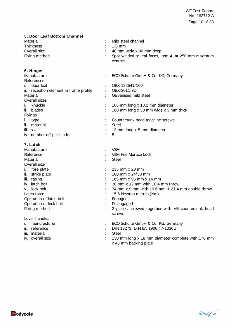
5. Door Leaf Bottom Channel Material : Mild steel channel Thickness : 1.0 mm Overall size : 48 mm wide x 30 mm deep Fixing method : Spot welded to leaf faces, item 4, at 250 mm maximum
centres 6. Hinges Manufacturer : ECO Schulte GmbH & Co. KG, Germany References i. door leaf : OBX-182541/160 ii. reception element in frame profile : OBX-3011-3D Material : Galvanised mild steel Overall sizes i. knuckle : 166 mm long x 18.2 mm diameter ii. blades : 160 mm long x 33 mm wide x 3 mm thick Fixings i. type : Countersunk head machine screws ii. material : Steel iii. size : 13 mm long x 5 mm diameter iv. number off per blade : 5 7. Latch Manufacturer : VBH Reference : VBH Fire Mortice Lock Material : Steel Overall size i. fore plate : 235 mm x 20 mm ii. strike plate : 180 mm x 24/38 mm iii. casing : 165 mm x 95 mm x 14 mm iv. latch bolt : 30 mm x 12 mm with 10.4 mm throw v. lock bolt : 34 mm x 9 mm with 10.6 mm & 21.4 mm double throw Latch force : 15.6 Newton metres (Nm) Operation of latch bolt : Engaged Operation of lock bolt : Disengaged Fixing method : 2 pieces screwed together with M5 countersunk head
screws Lever handles i. manufacturer : ECO Schulte GmbH & Co. KG, Germany ii. reference : DIN 18273, DIN EN 1906 47-1030U iii. material : Steel iv. overall size : 130 mm long x 18 mm diameter complete with 170 mm
x 46 mm backing plate

WF Test Report No. 163712 A
Page 11 of 33
8. Safety Bolt Material : Steel Overall size i. backing plate : 100 mm x 36 mm ii. bolt : 14.8 mm long x 12 mm diameter 9. Door Closer Manufacturer : Geze Reference : TS 4000 Material i. body : Cast alloy ii. cover box : Plastics iii. closer arm : Steel Overall size : 288 mm long x 60 mm high x 50 mm deep Fixing method : Unexposed face, through screwed to reinforcing plates
at head of each leaf Maximum opening moments : 46.5 Nm Maximum closing moments : 27.1 Nm

WF Test Report No. 163712 A
Page 12 of 33
Specimen Supporting Construction 18. Masonry Bricks Density : 1600 kg/m3
Strength : 50 N/mm2 Thickness : 102.5 mm Length : 215 mm Height : 65 mm Brick configuration : Half lap, stretcher bond with no finishes 19.Mortar Material : Cement, sand Mix ratio : 1 : 4
WF Test Report No. 163712 A
Page 13 of 33
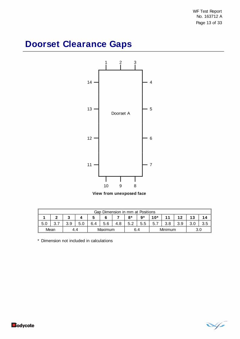
Doorset Clearance Gaps
1 2 3
14
4
13
5
Doorset A
12
6
11
7
10 9 8
View from unexposed face
Gap Dimension in mm at Positions 1 2 3 4 5 6 7 8* 9* 10* 11 12 13 14
5.0 3.7 3.9 5.0 6.4 5.6 4.8 5.2 5.5 5.7 3.8 3.9 3.0 3.5 Mean 4.4 Maximum 6.4 Minimum 3.0
* Dimension not included in calculations

WF Test Report No. 163712 A
Page 14 of 33
Instrumentation
General The instrumentation was provided in accordance with the requirements of the Standard.
Furnace The furnace was controlled so that its mean temperature complied with the requirements of BS EN 1363-1: 1999 Clause 5.1 using six plate thermometers, distributed over a plane 100 mm from the surface of the test construction.
General Thermocouples were provided to monitor the unexposed surface of the specimens and the output of all instrumentation was recorded at no less than one minute intervals as follows:
Thermocouples 2 to 6
At five positions on each doorset, one approximately at the centre and one at approximately the centre of each quarter section of each doorset.
Thermocouples 12 to 15
At four positions on each doorset, positioned at 100 mm in from the door leaf vertical edges, two at mid-height, and two at 100 mm below the top edge of each leaf.
Thermocouples 20 to 23
At two positions on the top horizontal frame and one position on each vertical frame member at mid-height of each doorframe.
The locations and reference numbers of the various unexposed surface thermocouples are shown in Figure 1.
Roving Thermocouple
A roving thermocouple was available to measure temperatures on the unexposed surface of the specimens at any position which might appear to be hotter than the temperatures indicated by the fixed thermocouples.
Integrity Criteria Cotton pads and gap gauges were available to evaluate the integrity of the specimens.
Radiation Water-cooled foil heat-flux meters were used to record the heat radiation from the specimens. The heat flux meters were positioned at a distance of 1 metre from the unexposed surface of each of the doorset.
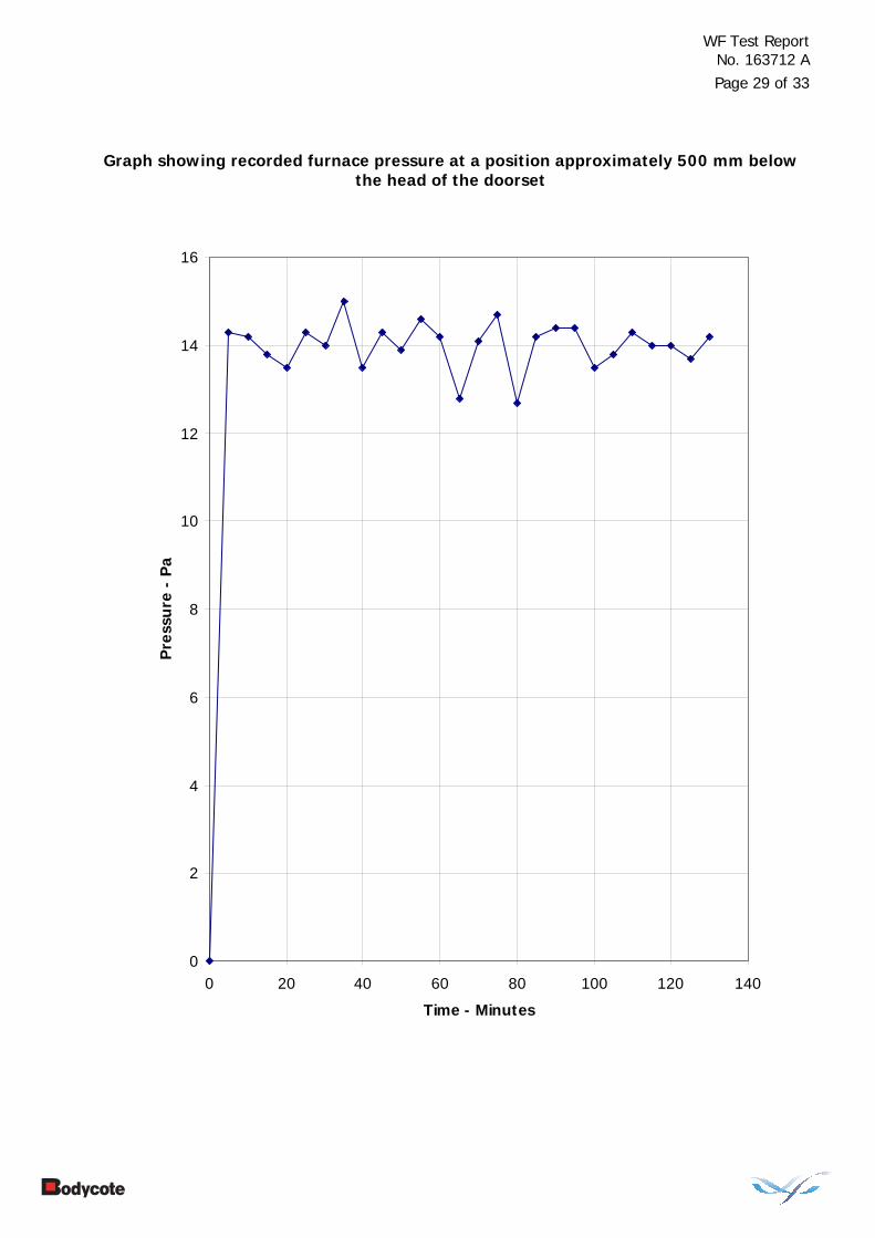
Furnace Pressure The furnace atmospheric pressure was controlled so that it complied with the requirements of BS EN 1363-1: 1999. Clause 5.2. The calculated pressure differential relative to the laboratory atmosphere at the top of the specimens was 14.8 (±3) Pa.
WF Test Report No. 163712 A
Page 15 of 33
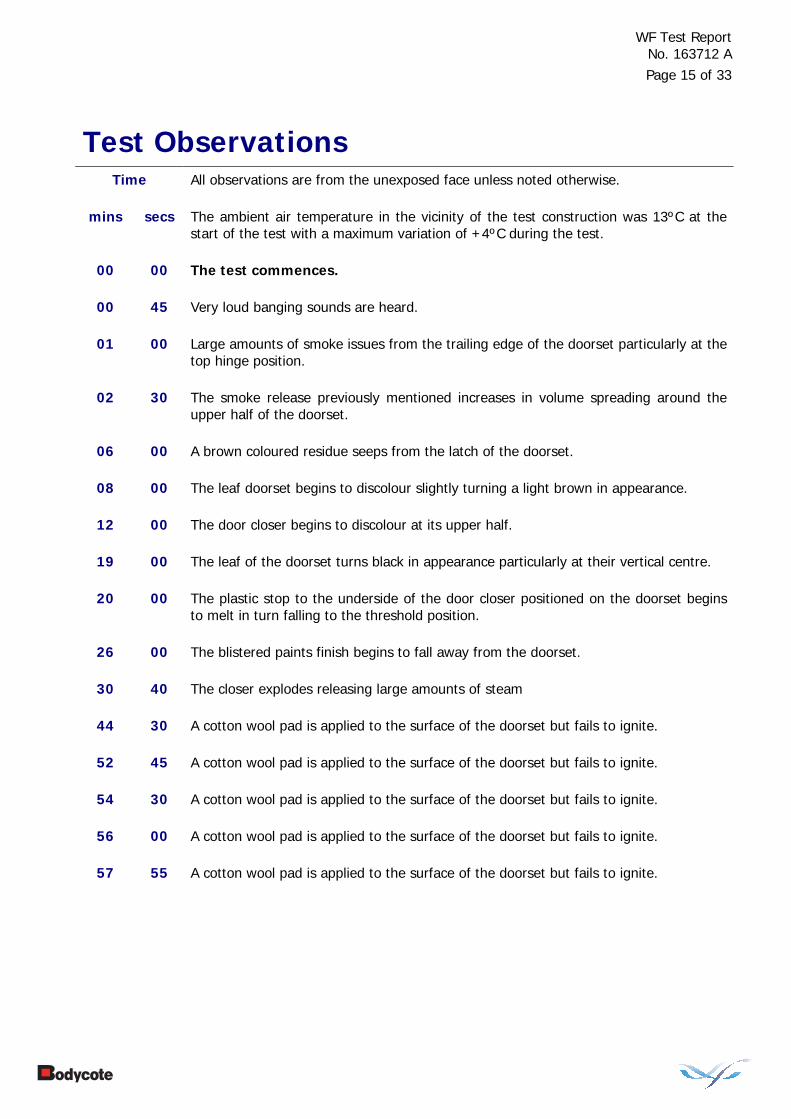
Test Observations Time All observations are from the unexposed face unless noted otherwise.
mins secs The ambient air temperature in the vicinity of the test construction was 13ºC at the start of the test with a maximum variation of +4ºC during the test.
00 00 The test commences.
00 45 Very loud banging sounds are heard.
01 00 Large amounts of smoke issues from the trailing edge of the doorset particularly at the top hinge position.
02 30 The smoke release previously mentioned increases in volume spreading around the upper half of the doorset.
06 00 A brown coloured residue seeps from the latch of the doorset.
08 00 The leaf doorset begins to discolour slightly turning a light brown in appearance.
12 00 The door closer begins to discolour at its upper half.
19 00 The leaf of the doorset turns black in appearance particularly at their vertical centre.
20 00 The plastic stop to the underside of the door closer positioned on the doorset begins to melt in turn falling to the threshold position.
26 00 The blistered paints finish begins to fall away from the doorset.
30 40 The closer explodes releasing large amounts of steam
44 30 A cotton wool pad is applied to the surface of the doorset but fails to ignite.
52 45 A cotton wool pad is applied to the surface of the doorset but fails to ignite.
54 30 A cotton wool pad is applied to the surface of the doorset but fails to ignite.
56 00 A cotton wool pad is applied to the surface of the doorset but fails to ignite.
57 55 A cotton wool pad is applied to the surface of the doorset but fails to ignite.

WF Test Report No. 163712 A
Page 16 of 33
Time
mins secs
60 00 The doorset continues to satisfy the test criteria.
61 00 A cotton wool pad is applied to the central position of the doorset and ignites. Cotton pad integrity failure is deemed to occur.
75 00 No further significant visible changes are evident.
96 00 Sustained flames issue from the trailing edge of the doorset. Sustained flaming integrity failure is deemed to occur.
133 00 The test is discontinued.

WF Test Report No. 163712 A
Page 17 of 33
Test Photographs
The exposed face of the doorsets prior to testing
The unexposed face of the doorsets prior to testing

WF Test Report No. 163712 A
Page 18 of 33
The unexposed face of the doorsets after 30 minutes of testing
The unexposed face of the doorsets after 60 minutes of testing

WF Test Report No. 163712 A
Page 19 of 33
The unexposed face of the doorsets after 90 minutes of testing
The unexposed face of the doorsets after 120 minutes of testing

WF Test Report No. 163712 A
Page 20 of 33
The exposed face of the doorsets immediately after testing

WF Test Report No. 163712 A
Page 21 of 33
Temperature, Radiation & Deflection Data
Mean furnace temperature, together with the temperature/time relationship specified in the Standard
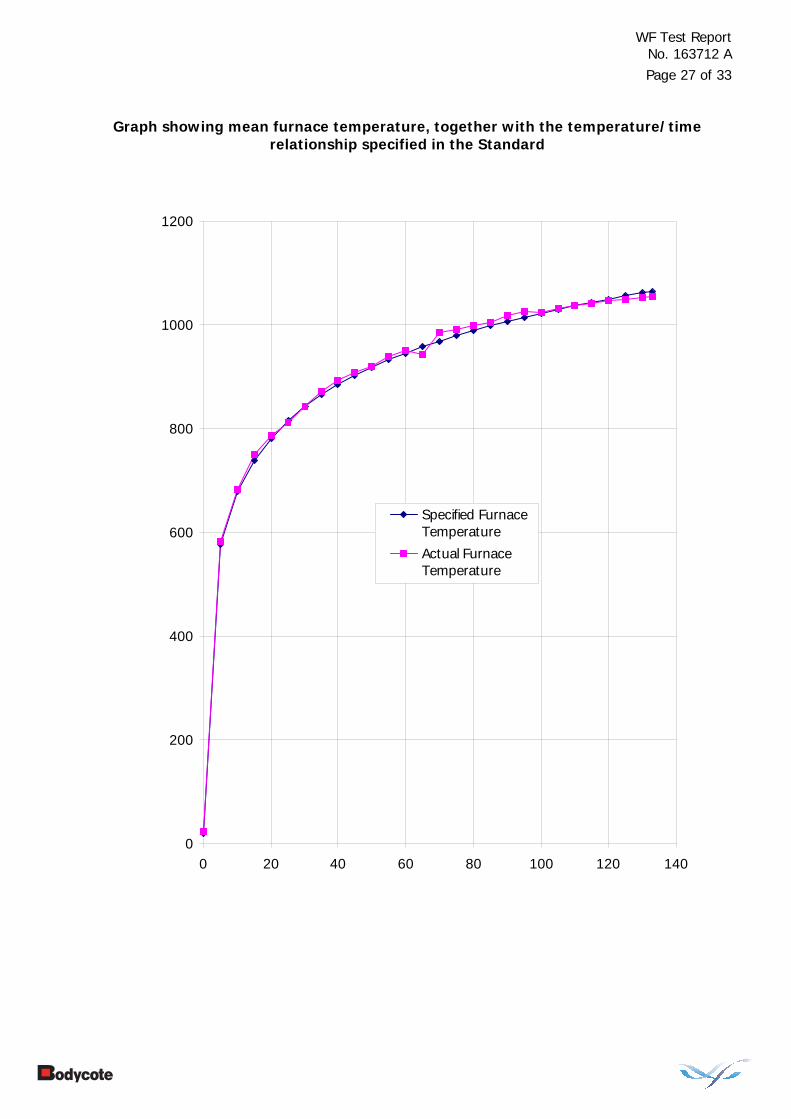
Time Specified Actual
Furnace Furnace Mins Temperature Temperature
Deg. C Deg. C 0 20 23 5 576 583 10 678 683 15 739 750 20 781 787 25 815 812 30 842 842 35 865 871 40 885 892 45 902 907 50 918 920 55 932 938 60 945 950 65 957 943 70 968 984 75 979 990 80 988 999 85 998 1003 90 1006 1017 95 1014 1025 100 1022 1024 105 1029 1030 110 1036 1036 115 1043 1040 120 1049 1046 125 1055 1048 130 1061 1052 133 1064 1054

WF Test Report No. 163712 A
Page 22 of 33
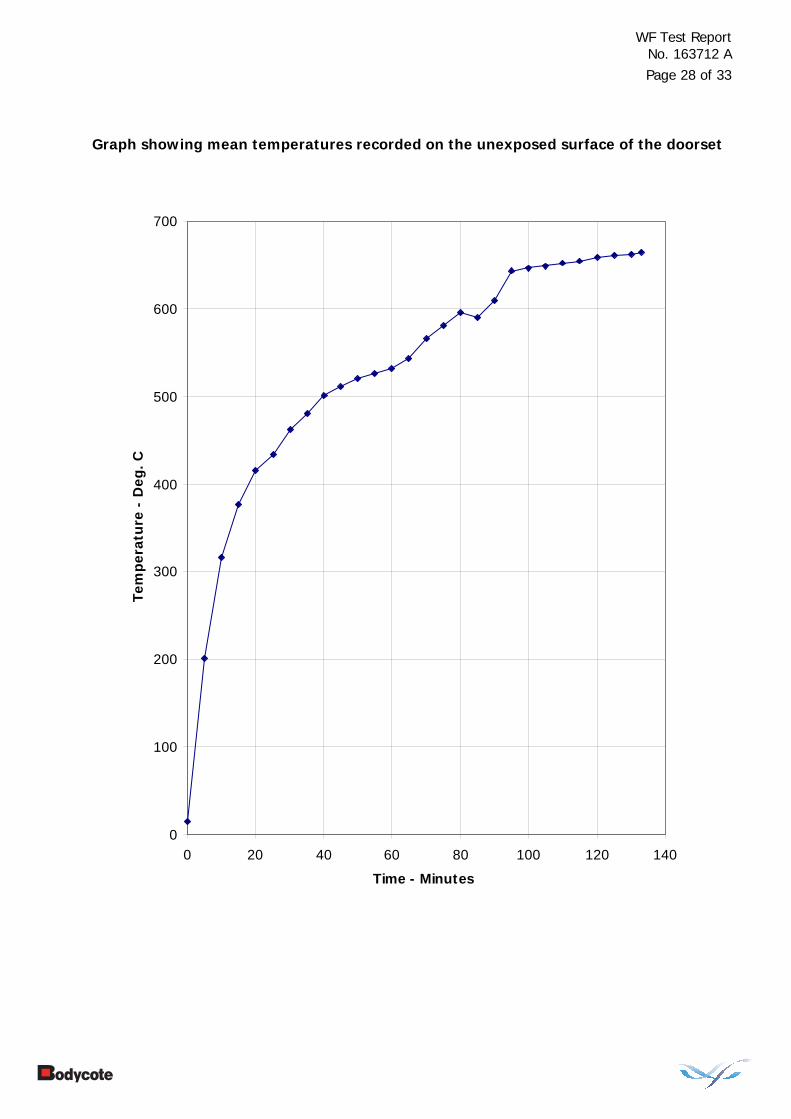
Individual and mean temperatures recorded on the unexposed surface of Doorset A
Time T/C T/C T/C T/C T/C Mean Number Number Number Number Number Temp.
Mins 2 3 4 5 6 Deg. C Deg. C Deg. C Deg. C Deg. C Deg. C 0 16 15 16 16 16 15 5 198 221 236 180 178 201 10 327 336 345 293 283 316 15 388 388 407 361 347 377 20 418 424 441 404 392 415 25 437 432 473 422 410 434 30 481 453 496 447 435 462 35 490 469 508 464 471 480 40 515 492 524 483 494 501 45 524 501 537 494 503 511 50 534 508 547 504 511 520 55 541 513 542 514 520 526 60 529 504 621 518 492 532 65 538 509 635 522 514 543 70 574 540 671 505 544 566 75 587 552 683 512 573 581 80 596 563 689 536 591 595 85 596 565 688 574 530 590 90 604 574 694 614 562 609 95 608 581 698 689 642 643 100 605 579 694 683 677 647 105 606 580 695 685 679 649 110 608 583 699 690 682 652 115 612 585 702 694 686 655 120 614 587 705 700 690 659 125 616 588 708 701 695 661 130 618 589 710 703 698 663 133 622 591 712 704 697 665
WF Test Report No. 163712 A
Page 23 of 33
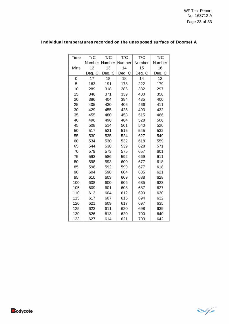
Individual temperatures recorded on the unexposed surface of Doorset A
Time T/C T/C T/C T/C T/C
Number Number Number Number Number Mins 12 13 14 15 16
Deg. C Deg. C Deg. C Deg. C Deg. C 0 17 18 18 14 13 5 163 191 178 222 179 10 289 318 286 332 297 15 346 371 339 400 358 20 386 404 384 435 400 25 405 430 406 466 411 30 429 455 428 493 432 35 455 480 458 515 466 40 496 498 484 528 506 45 508 514 501 540 520 50 517 521 515 545 532 55 530 535 524 627 549 60 534 530 532 618 559 65 544 538 539 628 571 70 579 573 575 657 601 75 593 586 592 669 611 80 598 593 600 677 618 85 598 592 599 677 618 90 604 598 604 685 621 95 610 603 609 688 628 100 608 600 606 685 623 105 609 601 608 687 627 110 613 604 612 690 630 115 617 607 616 694 632 120 621 609 617 697 635 125 623 611 620 698 639 130 626 613 620 700 640 133 627 614 621 703 642

WF Test Report No. 163712 A
Page 24 of 33
Individual temperatures recorded on the door frame of Doorset A
Time T/C T/C T/C T/C T/C Number Number Number Number Number
Mins 17 18 19 20 21 Deg. C Deg. C Deg. C Deg. C Deg. C 0 14 13 13 14 14 5 96 130 108 107 105 10 195 250 242 241 206 15 264 329 328 316 273 20 316 382 381 364 350 25 355 410 420 389 392 30 386 423 452 413 428 35 419 439 482 435 471 40 457 455 496 457 510 45 486 473 509 481 541 50 506 491 521 503 558 55 522 507 531 521 572 60 528 520 533 532 582 65 530 526 536 538 591 70 547 538 563 557 617 75 568 553 582 569 640 80 584 564 594 574 653 85 594 569 601 590 655 90 602 573 606 586 667 95 610 578 614 589 673 100 614 581 615 589 684 105 617 584 618 589 704 110 621 589 622 598 711 115 625 592 625 605 716 120 630 596 629 608 721 125 633 599 631 611 724 130 634 602 633 613 729 133 635 603 634 614 731
WF Test Report No. 163712 A
Page 25 of 33
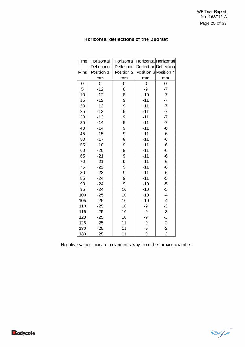
Horizontal deflections of the Doorset
Time Horizontal Horizontal HorizontalHorizontal Deflection Deflection Deflection Deflection
Mins Position 1 Position 2 Position 3 Position 4 mm mm mm mm 0 0 0 0 0 5 -12 6 -9 -7 10 -12 8 -10 -7 15 -12 9 -11 -7 20 -12 9 -11 -7 25 -13 9 -11 -7 30 -13 9 -11 -7 35 -14 9 -11 -7 40 -14 9 -11 -6 45 -15 9 -11 -6 50 -17 9 -11 -6 55 -18 9 -11 -6 60 -20 9 -11 -6 65 -21 9 -11 -6 70 -21 9 -11 -6 75 -22 9 -11 -6 80 -23 9 -11 -6 85 -24 9 -11 -5 90 -24 9 -10 -5 95 -24 10 -10 -5 100 -25 10 -10 -4 105 -25 10 -10 -4 110 -25 10 -9 -3 115 -25 10 -9 -3 120 -25 10 -9 -3 125 -25 11 -9 -2 130 -25 11 -9 -2 133 -25 11 -9 -2
Negative values indicate movement away from the furnace chamber
WF Test Report No. 163712 A
Page 26 of 33
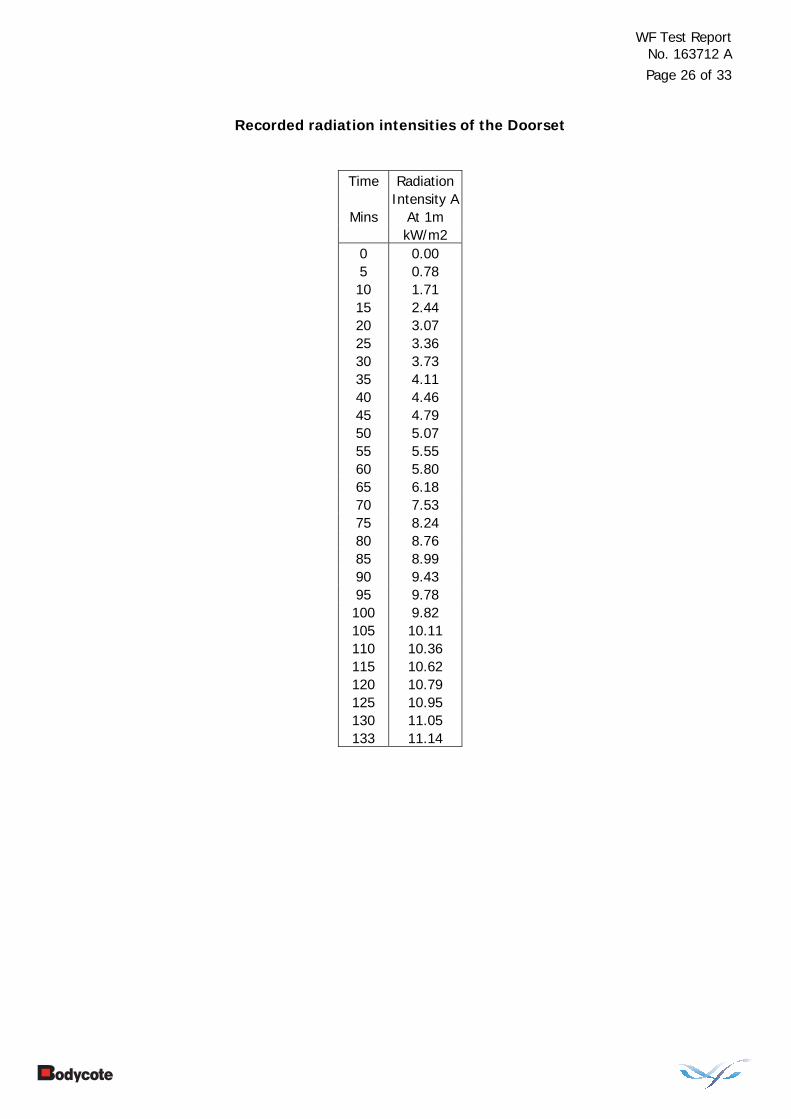
Recorded radiation intensities of the Doorset
Time Radiation Intensity A
Mins At 1m kW/m2 0 0.00 5 0.78 10 1.71 15 2.44 20 3.07 25 3.36 30 3.73 35 4.11 40 4.46 45 4.79 50 5.07 55 5.55 60 5.80 65 6.18 70 7.53 75 8.24 80 8.76 85 8.99 90 9.43 95 9.78 100 9.82 105 10.11 110 10.36 115 10.62 120 10.79 125 10.95 130 11.05 133 11.14
WF Test Report No. 163712 A
Page 27 of 33
Graph showing mean furnace temperature, together with the temperature/time
relationship specified in the Standard
0
200
400
600
800
1000
1200
0 20 40 60 80 100 120 140
Specified FurnaceTemperature
Actual FurnaceTemperature
WF Test Report No. 163712 A
Page 28 of 33
Graph showing mean temperatures recorded on the unexposed surface of the doorset
0
100
200
300
400
500
600
700
0 20 40 60 80 100 120 140
Time - Minutes
Tem
pera
ture
- D
eg. C
WF Test Report No. 163712 A
Page 29 of 33
Graph showing recorded furnace pressure at a position approximately 500 mm below the head of the doorset
0
2
4
6
8
10
12
14
16
0 20 40 60 80 100 120 140
Time - Minutes
Pre
ssu
re -
Pa

WF Test Report No. 163712 A
Page 30 of 33
Performance Criteria and Test Results
Integrity It is required that the specimens retain their separating function, without either causing ignition of a cotton pad when applied, or permitting the penetration of a gap gauge as specified in BS EN 1634-1: 2000, or resulting in sustained flaming on the unexposed surface. These requirements were satisfied for the periods shown below:
Integrity performance
Sustained flaming 96 minutes
Gap gauge 133 minutes*
Cotton pad 61 minutes
*The test duration.
Insulation The mean temperature rise of the unexposed surface shall not be greater than 140°C and that the maximum temperature rise shall not be greater than 180°C (except on the door frame, where the maximum temperature rise shall not exceed 360°C). Insulation failure also occurs simultaneously with integrity failure as specified in BS EN 1634-1: 2000. These requirements were satisfied for the period shown below:
Insulation performance
4 minutes
Radiation BS EN 1363-2: 1999 requires that the time for the measured radiation to exceed 5, 10, 15, 20 and 25 kW/m2 be reported. The readings given below are the average readings for each of the specimens.
Radiation Performance 5 kW/m2 10 kW/m2 15 kW/m2 20 kW/m2 25 kW/m2
49 minutes 102 minutes 133 minutes# 133 minutes# 133 minutes#
WF Test Report No. 163712 A
Page 31 of 33
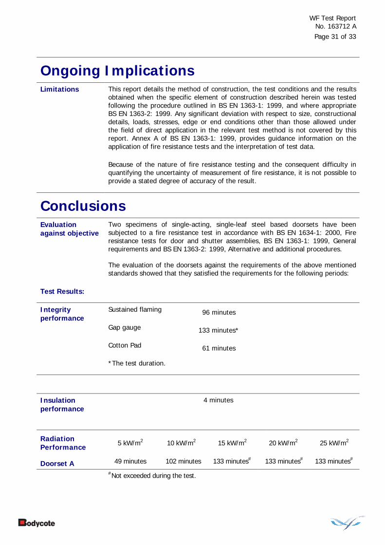
Ongoing Implications Limitations This report details the method of construction, the test conditions and the results
obtained when the specific element of construction described herein was tested following the procedure outlined in BS EN 1363-1: 1999, and where appropriate BS EN 1363-2: 1999. Any significant deviation with respect to size, constructional details, loads, stresses, edge or end conditions other than those allowed under the field of direct application in the relevant test method is not covered by this report. Annex A of BS EN 1363-1: 1999, provides guidance information on the application of fire resistance tests and the interpretation of test data.
Because of the nature of fire resistance testing and the consequent difficulty in quantifying the uncertainty of measurement of fire resistance, it is not possible to provide a stated degree of accuracy of the result.
Conclusions Evaluation against objective
Two specimens of single-acting, single-leaf steel based doorsets have been subjected to a fire resistance test in accordance with BS EN 1634-1: 2000, Fire resistance tests for door and shutter assemblies, BS EN 1363-1: 1999, General requirements and BS EN 1363-2: 1999, Alternative and additional procedures.
The evaluation of the doorsets against the requirements of the above mentioned standards showed that they satisfied the requirements for the following periods:
Test Results:
Sustained flaming 96 minutes
Gap gauge 133 minutes*
Integrity performance
Cotton Pad 61 minutes
*The test duration.
4 minutes Insulation performance
Radiation Performance 5 kW/m2 10 kW/m2 15 kW/m2 20 kW/m2 25 kW/m2
Doorset A 49 minutes 102 minutes 133 minutes# 133 minutes# 133 minutes#
#Not exceeded during the test.
WF Test Report No. 163712 A
Page 32 of 33
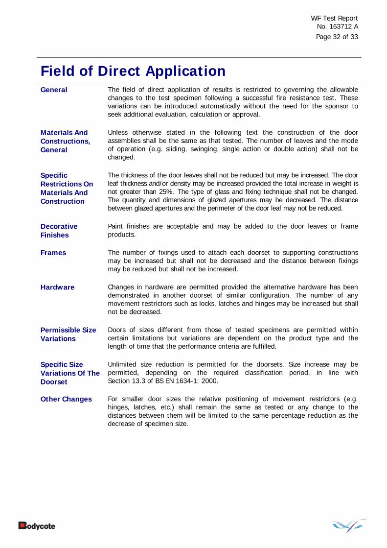
Field of Direct Application
General The field of direct application of results is restricted to governing the allowable changes to the test specimen following a successful fire resistance test. These variations can be introduced automatically without the need for the sponsor to seek additional evaluation, calculation or approval.
Materials And Constructions, General
Unless otherwise stated in the following text the construction of the door assemblies shall be the same as that tested. The number of leaves and the mode of operation (e.g. sliding, swinging, single action or double action) shall not be changed.
Specific Restrictions On Materials And Construction
The thickness of the door leaves shall not be reduced but may be increased. The door leaf thickness and/or density may be increased provided the total increase in weight is not greater than 25%. The type of glass and fixing technique shall not be changed. The quantity and dimensions of glazed apertures may be decreased. The distance between glazed apertures and the perimeter of the door leaf may not be reduced.
Decorative Finishes
Paint finishes are acceptable and may be added to the door leaves or frame products.
Frames The number of fixings used to attach each doorset to supporting constructions may be increased but shall not be decreased and the distance between fixings may be reduced but shall not be increased.
Hardware Changes in hardware are permitted provided the alternative hardware has been demonstrated in another doorset of similar configuration. The number of any movement restrictors such as locks, latches and hinges may be increased but shall not be decreased.
Permissible Size Variations
Doors of sizes different from those of tested specimens are permitted within certain limitations but variations are dependent on the product type and the length of time that the performance criteria are fulfilled.
Specific Size Variations Of The Doorset
Unlimited size reduction is permitted for the doorsets. Size increase may be permitted, depending on the required classification period, in line with Section 13.3 of BS EN 1634-1: 2000.
Other Changes For smaller door sizes the relative positioning of movement restrictors (e.g. hinges, latches, etc.) shall remain the same as tested or any change to the distances between them will be limited to the same percentage reduction as the decrease of specimen size.
WF Test Report No. 163712 A
Page 33 of 33
Asymmetrical Door Assemblies General
BS EN 1363-1 states that for separating elements required to be fire resisting from both sides, two specimens shall be tested (one from each direction) unless the element is fully symmetrical. However, in some cases it is possible to develop rules whereby the fire resistance of an asymmetrical door assembly tested in one direction can apply when the fire exposure is from the other direction. The possibility to develop such rules increases if the consideration is limited to certain types of door assembly and on the criteria being applicable, e.g. integrity only doors. The following rules represent the minimum level of common agreement which shall be followed. The rationale behind the rules is given in Annex C of BS EN 1634-1: 2000.
Specific Rules The doorsets were asymmetrical and were tested such that they opened away from the furnace chamber. The doorsets conformed with the specific rules given in 13.4.2 of BS EN 1634-1: 2000 which gives details of the applicability of the test results of doorsets tested in one direction to cover the opposite opening direction.
Supporting Constructions
The fire resistance of a door assembly tested in one form of standard supporting construction may or may not apply when it is mounted in other types of construction. In some cases it is possible for the result of a test on a particular type of door assembly tested in one form of standard supporting construction to be applicable to that door assembly when mounted in a different type of standard supporting construction.

Bodycote warringtonfire • Head Office • Holmesfield Road • Warrington • Cheshire • WA1 2DS • United KingdomTel: +44 (0) 1925 655 116 • Fax: +44 (0) 1925 655 419 • Email: [email protected] • Website: www.warringtonfire.net