12 TR /CERL ERDC DoD Corrosion Prevention and … of Corrosion-Resistant Coatings for...
52
ERDC/CERL TR-15-12 DoD Corrosion Prevention and Control Program Demonstration of Corrosion-Resistant Coatings for Air-Conditioning Coils and Fins Final Report on Project F10-AR01 Construction Engineering Research Laboratory Alfred D. Beitelman and Susan A Drozdz June 2015 Approved for public release; distribution is unlimited.
-
Upload
truongthuan -
Category
Documents
-
view
221 -
download
1
Transcript of 12 TR /CERL ERDC DoD Corrosion Prevention and … of Corrosion-Resistant Coatings for...

ERD
C/CE
RL T
R-15
-12
DoD Corrosion Prevention and Control Program
Demonstration of Corrosion-Resistant Coatings for Air-Conditioning Coils and Fins Final Report on Project F10-AR01
Cons
truc
tion
Engi
neer
ing
Res
earc
h La
bora
tory
Alfred D. Beitelman and Susan A Drozdz June 2015
Approved for public release; distribution is unlimited.

The US Army Engineer Research and Development Center (ERDC) solves the nation’s toughest engineering and environmental challenges. ERDC develops innovative solutions in civil and military engineering, geospatial sciences, water resources, and environmental sciences for the Army, the Department of Defense, civilian agencies, and our nation’s public good. Find out more at www.erdc.usace.army.mil.
To search for other technical reports published by ERDC, visit the ERDC online library at http://acwc.sdp.sirsi.net/client/default.

DoD Corrosion Prevention and Control Program
ERDC/CERL TR 15-12 June 2015
Demonstration of Corrosion-Resistant Coatings for Air-Conditioning Coils and Fins Final Report on Project F10-AR01
Alfred D. Beitelman and Susan A. Drozdz Construction Engineering Research Laboratory U.S. Army Engineer Research and Development Center 2902 Newmark Drive Champaign, IL 61822
Final report Approved for public release; distribution is unlimited.
Prepared for Office of the Secretary of Defense (OUSD(AT&L)) Washington, DC 20301-3090
Under Project F10-AR01, “Evaluation of Corrosion Resistant Coatings for Air Conditioning Coils in Hawaii”

ERDC/CERL TR-15-12 ii
Abstract
Department of Defense military installations operate air-conditioning equipment in humid and coastal locations that produce high levels of cor-rosion. Installation experience has shown that severe corrosion has re-duced expected equipment life cycles by up to 50%. This project for the Of-fice of the Secretary of Defense Corrosion Prevention and Control Program demonstrated and evaluated the performance characteristics of two corro-sion prevention coatings on condenser coils in highly corrosive environ-ments. This work assessed the capabilities and advantages of an alumi-num-impregnated polyurethane coating and a flexible epoxy polymer applied to two separate condenser units at Schofield Barracks, Hawaii. The work also included fabricating and exposing test coupons of various sub-strates, each coated with the two coating systems and a third coating commonly used in less-corrosive environments. These coupons were ex-posed both at the Schofield Barracks site and in a laboratory-accelerated exposure cabinet. The work recommends that copper rather than alumi-num components be specified in air conditioners operating in highly cor-rosive environments. A copper substrate protected with a newer type of corrosion coating is projected to extend the equipment’s expected life cycle from 7–10 years to 25–30 years. The return on investment for the project is 3.89.
DISCLAIMER: The contents of this report are not to be used for advertising, publication, or promotional purposes. Citation of trade names does not constitute an official endorsement or approval of the use of such commercial products. All product names and trademarks cited are the property of their respective owners. The findings of this report are not to be construed as an official Department of the Army position unless so designated by other authorized documents.
DESTROY THIS REPORT WHEN NO LONGER NEEDED. DO NOT RETURN IT TO THE ORIGINATOR.

ERDC/CERL TR-15-12 iii
Contents Abstract .................................................................................................................................... ii
Figures and Tables .................................................................................................................. iv
Preface ...................................................................................................................................... v
Executive Summary ................................................................................................................ vi
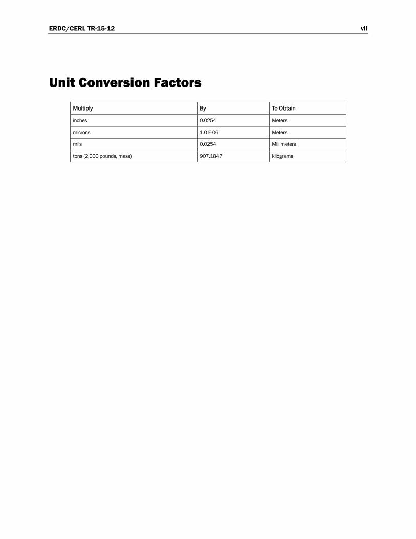
Unit Conversion Factors ........................................................................................................ vii
1 Introduction ...................................................................................................................... 1 1.1 Problem statement ............................................................................................ 1 1.2 Objective............................................................................................................. 2 1.3 Approach ............................................................................................................ 2
2 Technical Investigation ................................................................................................... 3 2.1 Technology overview .......................................................................................... 3 2.2 Field work ........................................................................................................... 4 2.3 Commissioning and monitoring ........................................................................ 7
2.3.1 Field operation and monitoring .................................................................................. 7 2.3.2 Laboratory-accelerated exposure testing and monitoring ........................................ 8
3 Discussion ....................................................................................................................... 10 3.1 Metrics.............................................................................................................. 10 3.2 Results.............................................................................................................. 10
3.2.1 On-site data ............................................................................................................... 10 3.2.2 Laboratory data ......................................................................................................... 14
3.3 Lessons learned .............................................................................................. 21
4 Economic Analysis ......................................................................................................... 22 4.1 Costs and assumptions .................................................................................. 22 4.2 Projected return on investment (ROI) ............................................................ 23
5 Conclusions and Recommendations ........................................................................... 25 5.1 Conclusions ..................................................................................................... 25 5.2 Recommendations ......................................................................................... 25
5.2.1 Applicability ............................................................................................................... 26 5.2.2 Implementation ......................................................................................................... 26
References ............................................................................................................................. 28
Appendix: Annual Assessment, Photo Documentation ................................................... 29
Report Documentation Page

ERDC/CERL TR-15-12 iv
Figures and Tables
Figures
Figure 1. Interior layout of a Carrier-brand condenser, shown with coated fins. ................... 3 Figure 2. A condenser area cleaned of debris, with new footings in place. .......................... 6 Figure 3. Positioning one of two new condenser units outside Schofield Barracks Bowling Center................................................................................................................................ 6 Figure 4. Two units in side-by-side configuration as installed at Schofield Barracks Bowling Center................................................................................................................................ 7 Figure 5. Aluminum coupon rack was fabricated to hold 12 coupons and mounted at each of the two condenser sites. ........................................................................... 8 Figure 6. Rack-1 coupons after 24 months of on-site field exposure. ................................. 13 Figure 7. Rack-2 coupons after 24 months of on-site field exposure. .................................. 13 Figure 8. Exfoliation of a bare aluminum coupon after 24 months of on-site field exposure........................................................................................................................................ 13 Figure 9. HVAC condenser fins with Coating E after on-site exposure for 24 months. ......................................................................................................................................... 14 Figure 10. HVAC condenser fins with Coating B after on-site exposure for 24 months. ......................................................................................................................................... 14 Figure 11. Accelerated-weathering coupons after 20 weeks of exposure. ......................... 16 Figure 12. Accelerated-weathering coupons remaining at conclusion of test after 52 weeks of exposure. ................................................................................................................ 17
Tables
Table 1. On-site coupons evaluations according to two industry standards, after 12 months and 24 months of exposure. .................................................................................. 11 Table 2. Rust ratings according to ASTM D610-07, “Standard Test Method for Evaluating Degree of Rusting on Painted Steel Surfaces.” .................................................... 12 Table 3. Blister ratings according to ASTM D714-02, “Standard Test Method for Evaluating Degree of Blistering of Paints.” ............................................................................... 12 Table 4. Alpha-numeric evaluation indicators of accelerated-weathering coupons at end of various observation periods according to ASTM D610 and D714. ...................... 18 Table 5. Detail for $670,000 project demonstration costs/funding. ................................... 22 Table 6. Baseline Case, costs and expected service life. ....................................................... 22 Table 7. Demonstrated Technology, costs and expected service life. ................................... 23 Table 8. ROI analysis. .................................................................................................................. 24

ERDC/CERL TR-15-12 v
Preface
This demonstration was performed for the Office of the Secretary of De-fense (OSD) under Department of Defense (DoD) Corrosion Control and Prevention Project F10AR01, “Evaluation of Corrosion Resistant Coatings for Air Conditioning Coils in Hawaii.” The proponent was the U.S. Army Office of the Assistant Chief of Staff for Installation Management (ACSIM), and the stakeholder was the U.S. Army Installation Management Command (IMCOM). The technical monitors were Daniel J. Dunmire (OUSD (AT&L) Corrosion) and David N. Purcell (DAIM-ODF).
The work was performed by the Materials Branch (CEERD-CF-M), Facili-ties Division (CF), U. S. Army Engineer and Structures Research and De-velopment Center – Construction Engineering Research Laboratory (ERDC-CERL), Champaign, IL. Significant portions of this work were per-formed by Christopher Olaes, Dave Butler, and Larry Clark from Mandaree Enterprise Corporation, Warner Robins, Georgia. At the time of publication, Vicki L. Van Blaricum was Chief CEERD-CF-M, L. Michael Golish was Chief, CEERD-CF, and Kurt Kinnevan, CEERD-CV-T, was the Technical Director for Adaptive and Resilient Installations. The Deputy Director of ERDC-CERL was Dr. Kirankumar Topudurti, and the Director was Dr. Ilker Adiguzel.
The following individuals are gratefully acknowledge for their contribu-tions to this project:
• Mr. Fred Ching, Directorate of Public Works, Schofield Barracks, Hawaii
• Mr. Greg Lee of Island Wide A/C Service, Honolulu, Hawaii
The Acting Commander of ERDC was LTC John T. Tucker III, and the Di-rector was Dr. Jeffery P. Holland.

ERDC/CERL TR-15-12 vi
Executive Summary
Department of Defense military installations operate air-conditioning (AC) equipment all over the world, including highly corrosive environments where their service life is shortened by damage from corrosion. Two newer coating technologies were selected and applied to the cooling vanes of air-conditioner condensers with the expectation they would better resist cor-rosion on common AC substrates of aluminum than the traditional, baked, phenolic coating systems which are brittle and easily damaged.
This project demonstrated and evaluated, over a 24-month period, the ability and cost effectiveness of two of the newer coatings to protect build-ing air-conditioning condenser evaporator coils and fins from corrosion. Exposure coupons made of various substrates received various coatings and were placed at the sites of the condensers in a highly corrosive envi-ronment at Schofield Barracks, Hawaii. Additional coupons with the same combinations of substrates and coatings were exposed in a laboratory’s ac-celerated-weathering test cabinets for 12 months, according to industry standards. Based on the test-cabinet results, copper will provide a longer service life than aluminum, and the service life of equipment can be fur-ther extended by the addition of a coating system. Equipment protected by one of the newer coatings is predicted to have a service life 3–4 times longer than equipment with traditional coatings. The return on investment ratio was calculated to be 3.89 over a 30-year period.
Based on the test cabinet results, it was recommended that HVAC compo-nents in highly corrosive environments be made of copper and coated with a manufacturer’s standard coating to extend the unit’s service life. It is recommended that the HVAC condensers and on-site coupons under this test be periodically revisited over the next 30 years, and the corrosion-protection performance of the two coating technologies be re-evaluated. Additional inspections will provide additional data to more accurately predict the life cycle of each coating used in this application. Recommen-dations were also made to update related military guidance documents to reflect findings of this effort for corrosion protection.
ERDC/CERL TR-15-12 vii
Unit Conversion Factors
Multiply By To Obtain
inches 0.0254 Meters
microns 1.0 E-06 Meters
mils 0.0254 Millimeters
tons (2,000 pounds, mass) 907.1847 kilograms

ERDC/CERL TR-15-12 viii
(This page intentionally left blank.)

ERDC/CERL TR-15-12 1
1 Introduction
1.1 Problem statement
Facilities located in highly corrosive environments operated by the Army and Department of Defense (DoD) are vulnerable to corrosion degradation of their air-conditioning (AC) coils and fins.
For example, the warm, humid island climate of Hawaii creates a high demand for AC; meanwhile, Hawaii’s ocean coastal location creates a high-chloride salt environment that is highly corrosive to the aluminum com-ponents of AC systems as well as to the steel components of the associated machinery and housing. According to the Department of Public Works at Schofield Barracks, Hawaii, an AC system is scoped for a 15–20 year ser-vice life, but the actual average service life in the highly corrosive envi-ronment is closer to 7–10 years. The DoD’s reported annual cost of all heating ventilation and cooling (HVAC)-related corrosion was $1.67 mil-lion or 21% of the total costs of facility corrosion (Herzberg et al. 2010). Extending the service life of HVAC units could reduce and control the costs of AC maintenance, repair, and replacement due to corrosion.
Coatings have been previously applied to the cooling vanes of AC conden-sers installed at DoD installations in Hawaii; however, the traditional, baked phenolic coating systems have presented a number of application and performance problems including: (a) phenolic coatings are brittle and easily damaged; (b) the dip or flow-coat methods used in their application often result in an uneven thickness of coating material; and (c) unevenness in coating material can bridge the narrow space between cooling fins and thereby reduce heat transfer efficiency and leave exposed bare metal be-hind the filled spaces (Meister 2000, 583).
Under this demonstration-evaluation program, two types of selected coat-ings were applied and evaluated on a fixed facility’s AC units at Schofield Barracks on the island of Oahu, Hawaii. There was a need to determine the life expectancy and efficiency for AC coils and fins coated with the two al-ternative coatings when compared to uncoated and phenolic-coated metal parts commonly used in less-corrosive environments.
ERDC/CERL TR-15-12 2
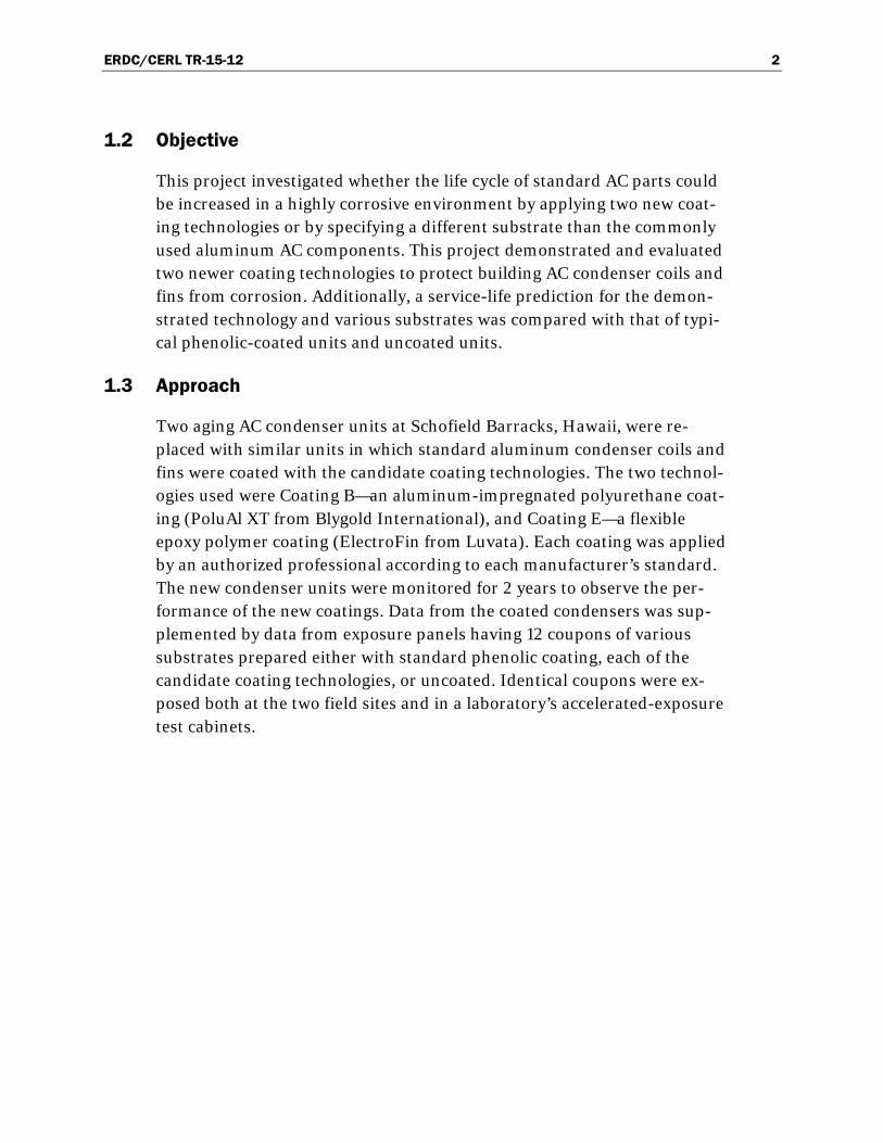
1.2 Objective
This project investigated whether the life cycle of standard AC parts could be increased in a highly corrosive environment by applying two new coat-ing technologies or by specifying a different substrate than the commonly used aluminum AC components. This project demonstrated and evaluated two newer coating technologies to protect building AC condenser coils and fins from corrosion. Additionally, a service-life prediction for the demon-strated technology and various substrates was compared with that of typi-cal phenolic-coated units and uncoated units.
1.3 Approach
Two aging AC condenser units at Schofield Barracks, Hawaii, were re-placed with similar units in which standard aluminum condenser coils and fins were coated with the candidate coating technologies. The two technol-ogies used were Coating B—an aluminum-impregnated polyurethane coat-ing (PoluAl XT from Blygold International), and Coating E—a flexible epoxy polymer coating (ElectroFin from Luvata). Each coating was applied by an authorized professional according to each manufacturer’s standard. The new condenser units were monitored for 2 years to observe the per-formance of the new coatings. Data from the coated condensers was sup-plemented by data from exposure panels having 12 coupons of various substrates prepared either with standard phenolic coating, each of the candidate coating technologies, or uncoated. Identical coupons were ex-posed both at the two field sites and in a laboratory’s accelerated-exposure test cabinets.
ERDC/CERL TR-15-12 3
2 Technical Investigation
2.1 Technology overview
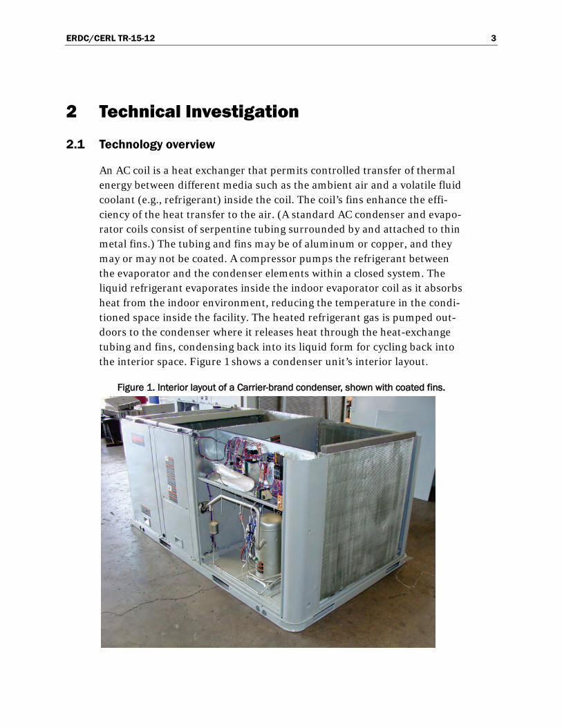
An AC coil is a heat exchanger that permits controlled transfer of thermal energy between different media such as the ambient air and a volatile fluid coolant (e.g., refrigerant) inside the coil. The coil’s fins enhance the effi-ciency of the heat transfer to the air. (A standard AC condenser and evapo-rator coils consist of serpentine tubing surrounded by and attached to thin metal fins.) The tubing and fins may be of aluminum or copper, and they may or may not be coated. A compressor pumps the refrigerant between the evaporator and the condenser elements within a closed system. The liquid refrigerant evaporates inside the indoor evaporator coil as it absorbs heat from the indoor environment, reducing the temperature in the condi-tioned space inside the facility. The heated refrigerant gas is pumped out-doors to the condenser where it releases heat through the heat-exchange tubing and fins, condensing back into its liquid form for cycling back into the interior space. Figure 1 shows a condenser unit’s interior layout.
Figure 1. Interior layout of a Carrier-brand condenser, shown with coated fins.

ERDC/CERL TR-15-12 4
Two Carrier-brand AC condensers (30-ton and 40-ton) were procured by Island Wide Air Conditioning Services of Honolulu, Hawaii, for installa-tion at the Schofield Barracks Bowling Center. These units and their ap-plied coatings (described in Section 2.2; example shown in Figure 1) were evaluated as replacements for pre-existing condensers which were re-moved during the project. However, the facility’s HVAC systems were not completely replaced under this project, and the original air-handling sys-tems were not involved with the project equipment replacement. Applica-tion of the newer coatings was done by electrocoating or a spray process to overcome the problems associated with the dip or flow-coat methods fused for phenolic coatings. As stated previously, the older processes often pro-duced uneven thickness of coating which could fill spaces between cooling fins, reducing heat-transfer efficiency and leaving exposed bare metal in areas behind the filled space.
After installation, the condenser systems were monitored along with cou-pons mounted on sample racks that were attached to each of the conden-sers. These field-exposed systems and coupons were monitored for 2 years. Additional coupons of substrates and coatings identical to the field-exposed coupons were exposed in a laboratory’s accelerated-testing cham-bers and monitored for 1 year.
2.2 Field work
The 30-ton condenser system was shipped to International Air Condition-ing Coatings Inc., a licensed Blygold applicator in Waipahu, Hawaii, for Coating B to be applied. Prior to coating, the condenser coils were disas-sembled and rinsed by using a high-pressure warm-water spray system and then inspected for bent fins to ensure adequate spacing. The coils were then degreased with a pH-neutral detergent, to remove any manufac-turing oils and soiling, and then rinsed again. A chromate-free conversion layer was applied to the coil by using an air-assisted airless spray gun to achieve total coverage and penetration. Upon curing of the primer, the aluminum-impregnated polyurethane topcoat (Coating B) was applied by using air-assisted airless spray equipment to ensure total penetration and coverage without bridging or significantly affecting the heat-transfer abil-ity of the coil. The total dry film thickness of the top coat was between 20–25 microns. After curing, the coils were reassembled into the condenser unit and delivered to Schofield Barracks.
ERDC/CERL TR-15-12 5
The 40-ton condenser unit was received by Island Wide Air Conditioning Services with Coating E preapplied by the manufacturer’s factory in Texas. Coating E is a water-based, flexible, epoxy polymer coating process engi-neered specifically for HVAC/R heat-transfer coils. The electrocoating process performed by Carrier consisted of submerging the metallic coils in a paint/water bath where an electrical charge was used to deposit paint onto the coils.
The removal and replacement operation for each condenser was conduct-ed during two separate weeks to avoid interruption in the bowling center’s operation and to minimize impacts on the air-conditioning system’s load while one unit was down. Prior to removing each existing condenser, pow-er was disconnected from the unit and refrigerant liquids were vacuum-drained from the system. All copper plumbing connected to the interior units of each AC system was cut away to allow for the existing condenser’s removal. A crane was used to lift the existing unit over the block retaining wall. Once the existing condenser was removed, the area was cleaned of all debris and new cushioned footings were installed for the new condenser. The crane was used again to lift the new condenser over the retaining wall and position it on the footings. New copper plumbing along with new re-frigerant ball valves were installed and connected to the interior systems. Upon completion of the plumbing installation, new R-22 refrigerant was pumped through the system and primed. Electrical power was connected to the unit, and it was commissioned. This process was repeated for the second unit. Figure 2 and Figure 3 show the location of one of the units and its installation. The two condensers were located adjacent to each oth-er outside the Schofield Barracks Bowling Center, as shown in Figure 4.

ERDC/CERL TR-15-12 6
Figure 2. A condenser area cleaned of debris, with new footings in place.
Figure 3. Positioning one of two new condenser units outside Schofield Barracks Bowling Center.

ERDC/CERL TR-15-12 7
Figure 4. Two units in side-by-side configuration as installed at Schofield Barracks Bowling Center.
2.3 Commissioning and monitoring
2.3.1 Field operation and monitoring
An aluminum exposure rack was fabricated for placement at each of the two AC condenser locations (Figure 5). Each rack was designed to isolate 12 coupons that were 1 in. wide x 2 in. long x 1/8 in. thick from any galvan-ic effects of other metals. Each rack contained four copper coupons, four 1010 steel coupons, and four 2024-T3 aluminum coupons. A single coupon of each material was coated by Carrier with Coating E. Similarly, a single coupon of each material was coated by International Air Conditioning Coatings with Coating B, and IFM Effector, Inc. of Exton, Pennsylvania, coated coupons of each material with the phenolic coating commonly used by Carrier for condensers in less-corrosive environments. The remaining coupons were left bare. Each coupon used in this program was printed with a distinctive code indicating: (a) the substrate, (b) the coating, and (c) a consecutive number for the system. The coupons and each condenser unit were photographed and assessed at 12 months and 24 months after installation. Additional photographs of the on-site coupon racks are shown in Section 3.2 and the appendix of this report. Observations of blistering

ERDC/CERL TR-15-12 8
and rusting were recorded according to industry rating standards (ASTM 2009, 2012), as shown by Table 1 in Chapter 3.
Figure 5. Aluminum coupon rack was fabricated to hold 12 coupons and mounted at each of the two condenser sites.
2.3.2 Laboratory-accelerated exposure testing and monitoring
Additional coupons, comprised of substrates and coatings identical to the field-exposed coupons, were prepared and exposed in a laboratory’s accel-erated-exposure cabinets. Testing was conducted according to ASTM standard D 5894 (ASTM 2010). According to this standard, specimens were exposed to alternating periods of 1 week in a fluorescent UV/condensation chamber followed by 1 week in a cyclic salt fog/dry chamber, throughout the 52-week period for this portion of the project. The exposure chambers used were manufactured by the Q-Lab Corp, Cleveland, Ohio; the chambers included a Q-Fog Model Q-FOG-SSP-600 and a UV chamber Model QUV-SE. Observations of blistering and rusting were recorded according to industry rating standards (ASTM 2009, 2012), as shown by Table 4 in Chapter 3.
An anomaly occurred in the preparation of the exposure coupons. The ini-tial set of coupons with phenolic coating had a coating thickness typically in the area of 3.5–4.0 mils. This thickness was significantly in excess of the 2.5–3.0 mils recommended for condenser coatings in UFGS 23 81 00.00

ERDC/CERL TR-15-12 9
20, “Unitary Air Conditioning Equipment” (DoD 2009, par. 2.6.1, “Phenol-ic Coatings”). As a result, a new set of coupons was prepared with the proper prescribed coating thickness. This anomaly resulted in a 12-week delay in the exposure of the proper phenolic-coated coupons (i.e., data was recorded at 8 weeks and not again until 20 weeks). The appendix to this report gives additional notes about the process, and the anomaly did not affect the conclusions given in Chapter 5.

ERDC/CERL TR-15-12 10
3 Discussion
3.1 Metrics
The results of the project were assessed against a performance goal of min-imal degradation of the coating and minimal corrosion of the condenser fins over the performance evaluation period. The exposure coupons and condenser units were visually assessed using criteria from ASTM D714, “Standard Test Method for Evaluating Degree of Blistering of Paints” (ASTM 2009) and ASTM D610 “Standard Test Method for Evaluating De-gree of Rusting on Painted Steel Surfaces” (ASTM 2012). Although ASTM D610 is intended to be used for steel surfaces, the criteria therein were used for the evaluation of visual corrosion on the copper and aluminum coupons.
3.2 Results
3.2.1 On-site data
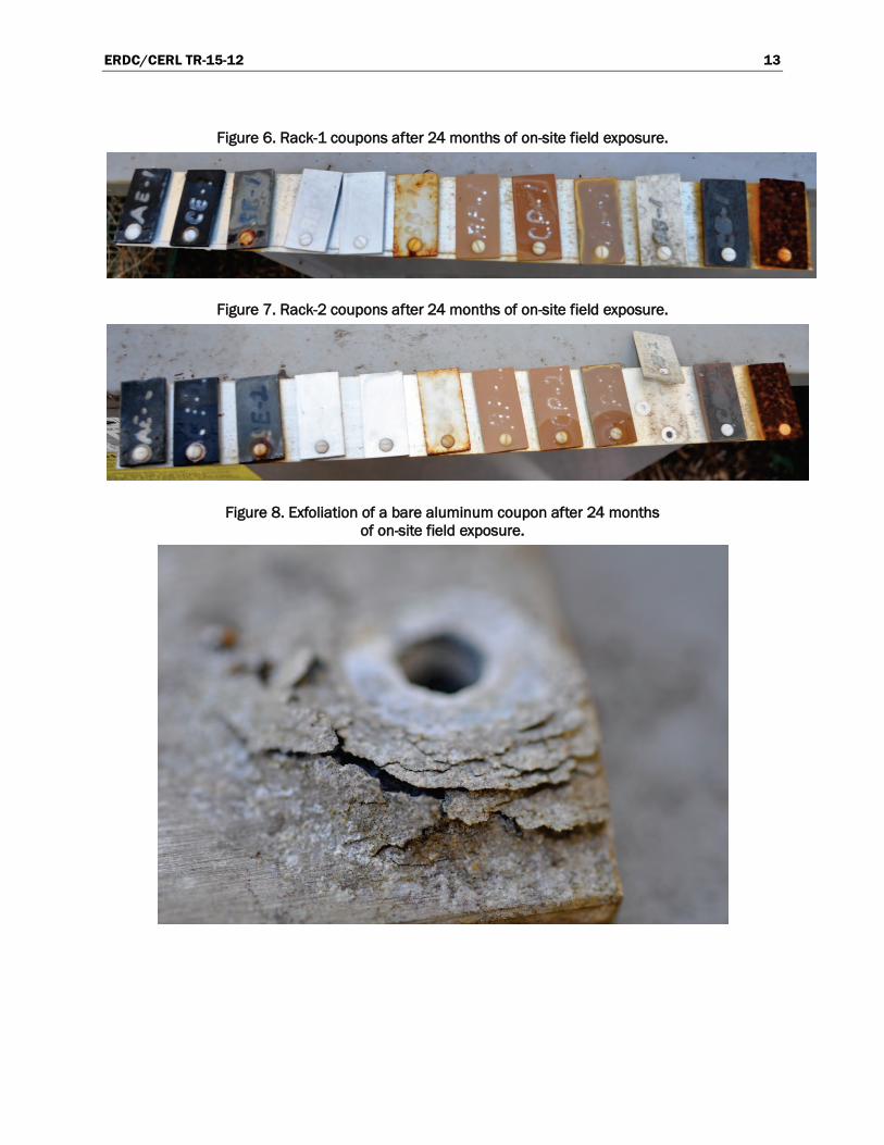
The two racks of field-exposed coupons were photographed and evaluated annually for a 24-month period in accordance with ASTM D714 and with ASTM D610 (ASTM 2009, 2012). Alpha-numeric results of the evaluations are shown in Table 1 (with explanation of rating standards in Table 2and Table 3). Photographic evidence is shown in Figure 6–Figure 10.
The following observations were made from the evaluation data:
• The phenolic coating and Coating B failed to protect the steel sub-strates at both of the on-site locations.
• Rust and blistering were most prominent on the edges of each coupon. • Blistering on the aluminum and copper coupons was substantially less. • The phenolic coating adhered better to the aluminum and copper cou-
pons than did Coating B and Coating A. • The uncoated coupons showed severe signs of corrosion on 100% of the
material within 12 months of exposure. • The bare aluminum coupon on Rack 2 began to crack and separate into
layers from exfoliation corrosion, causing the coupon to break away from the nylon fastener (Figure 7).
• The uncoated aluminum surface of the condenser exterior showed sig-nificant corrosion after 24 months of exposure (Figure 8).

ERDC/CERL TR-15-12 11
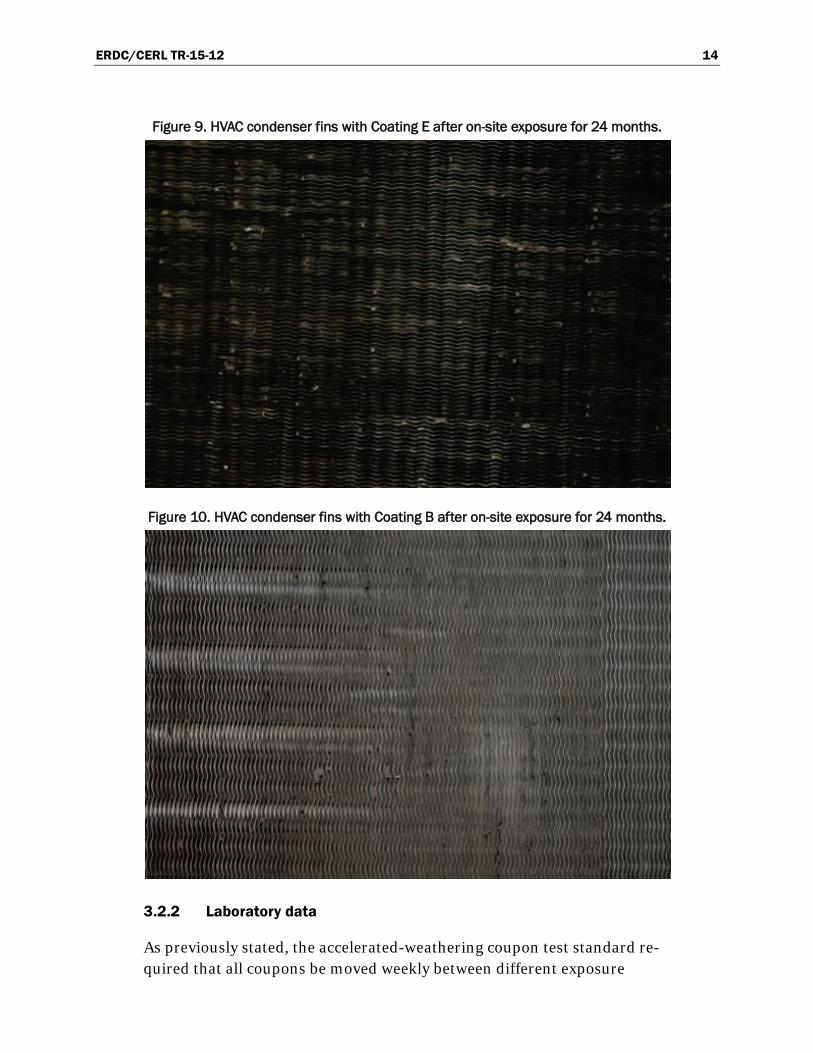
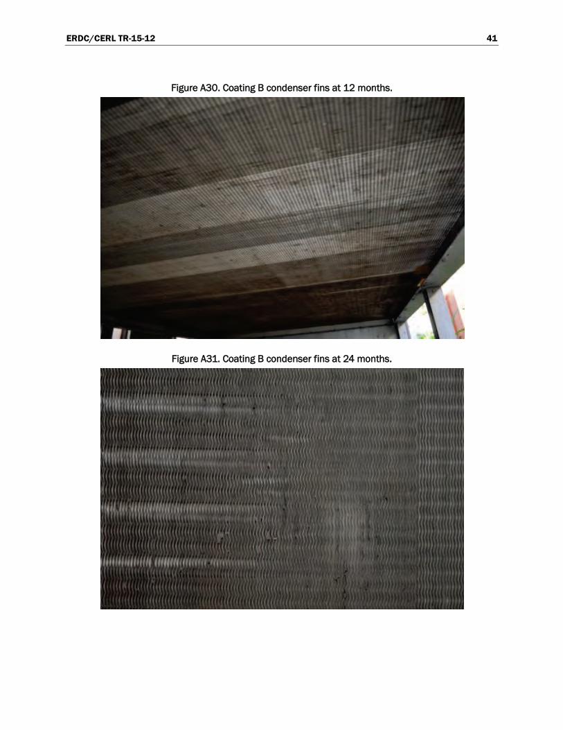
• The condenser fins coated with Coating B and Coating E showed no visible signs of corrosion or coating failures after 24 months of expo-sure (Figure 9 and Figure 10).
Additional photographs of on-site coupons and condenser fins are shown in the appendix of this report.
Table 1. On-site coupons evaluations according to two industry standards, after 12 months and 24 months of exposure.1
Coupon*
ASTM D610 ASTM D714
(12-mo.) (24-mo.) (12-mo.) (24-mo.)
AE-1 10 10 8F 6F
CE-1 10 10 8F 8F
SE-1 10 10 2D 2D
AB-1 10 10 10 10
CB-1 10 10 10 10
SB-1 4S 2G 4M 2M
AP-1 10 10 10 10
CP-1 10 10 10 8F
SP-1 8S 5S 10 10
AR-1 0 0 N/A N/A
CR-1 0 0 N/A N/A
SR-1 0 0 N/A N/A
AE-2 10 10 8F 8F
CE-2 10 10 8F 8F
SE-2 10 10 2D 2D
AB-2 10 10 10 2D
CB-2 10 10 10 10
SB-2 4S 3G 4M 4D
AP-2 10 10 10 10
CP-2 10 10 10 10
SP-2 6S 4S 10 8F
AR-2 0 0 n/a n/a
CR-2 0 0 n/a n/a
SR-2 0 0 n/a n/a
Key to coupon codes: 1st Character = Substrate (A=Aluminum, C=Copper, S=Steel)
2nd Character = Coating (B=Blygod, E= ElectroFin; P=phenolic; R=uncoated)
3rd Character = Rack No. (1,2)
1 Note: key to coupon codes is given at end of this table, and key ratings standards are given in Table 2
and Table 3 that follow.

ERDC/CERL TR-15-12 12
Table 2. Rust ratings according to ASTM D610-07, “Standard Test Method for Evaluating Degree of Rusting on Painted Steel Surfaces.”
Scale Rating Percentage of Surface Found Rusted
Expression of Rust Found (S=spots; G=general; P=pinpoint
10 ≤0.01 (none)
9 >0.01 to 0.03 9S, 9G, 9P
8 >0.03 to 0.1 8S, 8G, 8P
7 >0.1 to 0.3 7S, 7G, 7P
6 >0.3 to 1.0 6S, 6G, 6P
5 >1.0 to 3.0 5S, 5G, 5P
4 >3.0 to 10.0 4S, 4G, 4P,
3 >10.0 to 16.0 3S, 3G, 3P
2 >16.0 to 33.0 2S, 2G, 2P
1 >33.0 to 50.0 1S, 1G, 1P
0 >50.0 (none)
Table 3. Blister ratings according to ASTM D714-02, “Standard Test Method for Evaluating Degree of Blistering of Paints.”
Scale Description of Reference Standards
Size Reference standards have been selected for four steps as to size on a numerical scale from 10 to 0, in which No. 10 represents no blistering. Blistering standard No. 8 represents the smallest size blister easily seen by the unaided eye. Blistering standards Nos. 6, 4, and 2 represent progressively larger sizes.
Frequency Reference standards have been selected for four steps in frequency at each step in size, designated as follows:
D = MD =
M = F =
dense medium dense medium few
ERDC/CERL TR-15-12 13
Figure 6. Rack-1 coupons after 24 months of on-site field exposure.
Figure 7. Rack-2 coupons after 24 months of on-site field exposure.
Figure 8. Exfoliation of a bare aluminum coupon after 24 months of on-site field exposure.
ERDC/CERL TR-15-12 14
Figure 9. HVAC condenser fins with Coating E after on-site exposure for 24 months.
Figure 10. HVAC condenser fins with Coating B after on-site exposure for 24 months.
3.2.2 Laboratory data
As previously stated, the accelerated-weathering coupon test standard re-quired that all coupons be moved weekly between different exposure

ERDC/CERL TR-15-12 15
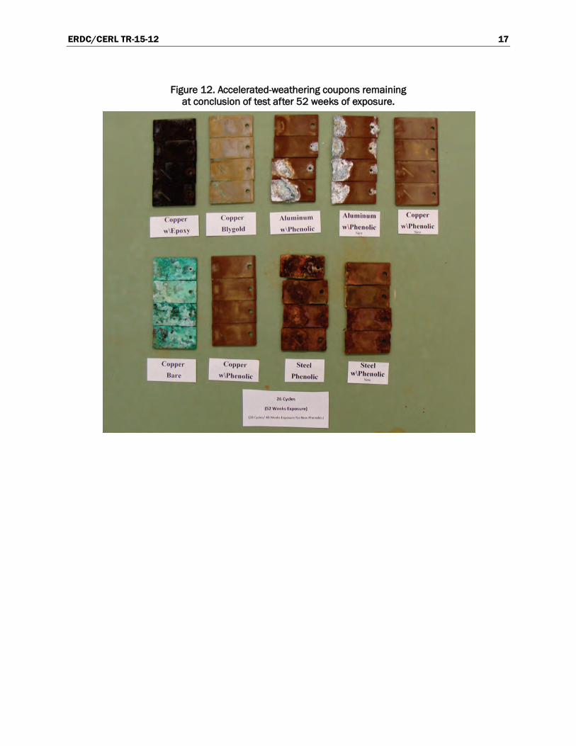
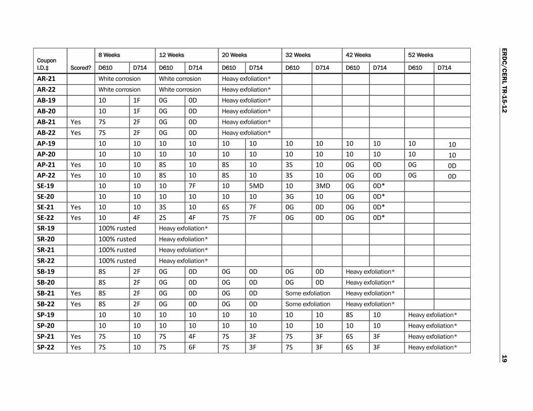
chambers (ASTM 2009). For the accelerated weathering tests, two from each set of four coated coupons were scored (scratched) to bare metal so the ability of the coating to resist undercutting could be evaluated. The ac-celerated-weathering coupon test for this project occurred over 52 weeks. Each time the coupons were transferred, a determination was made re-garding the need to document changes in the condition of the coatings. Documentation recorded at 8, 12, 20, 32, 42, and 52 weeks for the initial set of coupons is shown in Table 4. The replacement coupons coated with the proper thickness of phenolic (thinner coating) were documented at 8, 20, 30, and 40 weeks (see Table 4). Photographic documentation of the coupons after 20 weeks of exposure is shown in Figure 11. During the course of testing, coupons were removed from testing once the corrosion became severe (with significant metal loss). These coupons included the aluminum and steel panels with Coatings E and B, and the bare aluminum and epoxy panels. The remaining coupons at the conclusion of testing are shown in Figure 12.
Review of accelerated-weathering data in Table 4 shows the copper sub-strate to be the superior substrate. Uncoated, it quickly developed a green copper oxide patina that progressively grew thicker, eventually flaking off the surface at 32-weeks. Coupons that were scored developed a minor amount of oxides in the score, but the oxide development seemed to seal the score from further corrosion. Clearly, copper is the superior substrate, but the exposure did not indicate any difference in the performance of the various coatings applied to it because all coatings performed similarly well on the copper substrate.
Aluminum is a common fin material used in AC condensers that are not exposed to highly corrosive atmospheres. Because aluminum costs consid-erably less than copper, it was hoped that a high-quality coating (such as the demonstrated technologies) would protect aluminum from corrosion, even in more corrosive atmospheres. Clearly, each of the coatings did pro-vide a level of protection. Coating B provided the lowest level of protection, with ratings of “0” for both corrosion and blistering in as little as 12 weeks. The scored panels coated with the Coating E epoxy suffered the same level of failure in the same 12-week length of time, but the unscored coupons had a slightly better rating at the 20-week rating period. The phenolic coatings provided the highest level of protection on aluminum. On un-scored coupons, the excessively thick phenolic coatings provided a high level of protection at the end of the test period, and the standard-thickness

ERDC/CERL TR-15-12 16
phenolic coating was still providing a good level of protection after 40 weeks of exposure. On coupons where the phenolic was scored, the sub-strate began to deteriorate at the score early in the test; this deterioration eventually resulted in exfoliation under the coating. As the aluminum de-terioration progressed under the coating, it was often difficult to deter-mine if there was actual blistering associated with the coating, and this dif-ficulty perhaps resulted in some anomalies in the recorded blistering values. Whether the deterioration was recorded as blistering or general de-terioration, the anomalies did not affect the overall assessment of each coating.
Steel is never used for condenser fins, but the material is used elsewhere in the condenser framework and housing. On this substrate, the excessively thick phenolic coating provided the highest level of protection, with the standard thickness still providing performance similar to or slightly supe-rior to that of Coating E. The steel coupons with Coating B had total sub-strate failure in as little as 12 weeks, with exfoliation of the scored panels in 32 weeks.
Figure 11. Accelerated-weathering coupons after 20 weeks of exposure.
ERDC/CERL TR-15-12 17
Figure 12. Accelerated-weathering coupons remaining at conclusion of test after 52 weeks of exposure.

ERD
C/CER
L TR-15-12
18
Table 4. Alpha-numeric evaluation indicators of accelerated-weathering coupons at end of various observation periods according to ASTM D610 and D714.2
Coupon I.D.‡ Scored?
8 Weeks 12 Weeks 20 Weeks 32 Weeks 42 Weeks 52 Weeks
D610 D714 D610 D714 D610 D714 D610 D714 D610 D714 D610 D714
CE-19 10 10 10 10 10 10 10 10 10 10 10 10 CE-20 10 10 10 10 10 10 10 10 10 10 10 10 CE-21 Yes 10 10 10 10 10 10 10 10 10 10 10 10 CE-22 Yes 10 10 10 10 10 10 10 10 10 10 10 10 CR-19 Green oxide Green oxide Green oxide Green oxide Green oxide Green oxide
CR-20 Green oxide Green oxide Green oxide Green oxide Green oxide Green oxide
CR-21 Green oxide Green oxide Green oxide Green oxide Green oxide Green oxide
CR-22 Green oxide Green oxide Green oxide Green oxide Green oxide Green oxide
CB-19 Yes 10 10 10 10 10 10 10 10 10 10 10 10 CB-20 Yes 10 10 10 10 10 10 10 10 10 10 10 10 CB-21 10 10 10 10 10 10 10 10 10 10 10 10 CB-22 10 10 10 10 10 10 10 10 10 10 10 10 CP-19 10 10 10 10 10 10 10 10 10 10 10 10 CP-20 10 10 10 10 10 10 10 10 10 10 10 10 CP-21 Yes 10 10 10 10 10 10 10 10 10 10 10 10 CP-22 Yes 10 10 10 10 10 10 10 10 10 10 10 10 AE-19 10 10 10 1D 4S 4D*
AE-20 10 10 7S 4D 0G 2D* AE-21 Yes 9S 4F 0G 0D Heavy exfoliation* AE-22 Yes 10 1F 0G 0D Heavy exfoliation* AR-19 White corrosion White corrosion Heavy exfoliation* AR-20 White corrosion White corrosion Heavy exfoliation*
2 Note: key to coupon codes is given at end of this table, and keys to ratings standards were given in Table 2 and Table 3.
ERD
C/CER
L TR-15-12
19
Coupon I.D.‡ Scored?
8 Weeks 12 Weeks 20 Weeks 32 Weeks 42 Weeks 52 Weeks
D610 D714 D610 D714 D610 D714 D610 D714 D610 D714 D610 D714
AR-21 White corrosion White corrosion Heavy exfoliation* AR-22 White corrosion White corrosion Heavy exfoliation* AB-19 10 1F 0G 0D Heavy exfoliation* AB-20 10 1F 0G 0D Heavy exfoliation* AB-21 Yes 7S 2F 0G 0D Heavy exfoliation* AB-22 Yes 7S 2F 0G 0D Heavy exfoliation* AP-19 10 10 10 10 10 10 10 10 10 10 10 10
AP-20 10 10 10 10 10 10 10 10 10 10 10 10 AP-21 Yes 10 10 8S 10 8S 10 3S 10 0G 0D 0G 0D AP-22 Yes 10 10 8S 10 8S 10 3S 10 0G 0D 0G 0D SE-19 10 10 10 7F 10 5MD 10 3MD 0G 0D*
SE-20 10 10 10 10 10 10 3G 10 0G 0D* SE-21 Yes 10 10 3S 10 6S 7F 0G 0D 0G 0D* SE-22 Yes 10 4F 2S 4F 7S 7F 0G 0D 0G 0D* SR-19 100% rusted Heavy exfoliation* SR-20 100% rusted Heavy exfoliation* SR-21 100% rusted Heavy exfoliation*
SR-22 100% rusted Heavy exfoliation* SB-19 8S 2F 0G 0D 0G 0D 0G 0D Heavy exfoliation* SB-20 8S 2F 0G 0D 0G 0D 0G 0D Heavy exfoliation* SB-21 Yes 8S 2F 0G 0D 0G 0D Some exfoliation Heavy exfoliation* SB-22 Yes 8S 2F 0G 0D 0G 0D Some exfoliation Heavy exfoliation* SP-19 10 10 10 10 10 10 10 10 8S 10 Heavy exfoliation*
SP-20 10 10 10 10 10 10 10 10 10 10 Heavy exfoliation*
SP-21 Yes 7S 10 7S 4F 7S 3F 7S 3F 6S 3F Heavy exfoliation*
SP-22 Yes 7S 10 7S 6F 7S 3F 7S 3F 6S 3F Heavy exfoliation*

ERD
C/CER
L TR-15-12
20
Coupon I.D.‡ Scored?
8 Weeks 12 Weeks 20 Weeks 32 Weeks 42 Weeks 52 Weeks
D610 D714 D610 D714 D610 D714 D610 D714 D610 D714 D610 D714
Phenolic at standard thickness Coupon ID Score 8 Weeks (12-week delay to
recoat coupons at standard thickness)
20 Weeks 30 Weeks 40 Weeks NOTE: due to 12-week delay, 40 weeks of exposure equaled end of project for this coupon.
CP-4 10 10 n/a na/ 10 10 10 10 10 10 CP-5 10 10 n/a na/ 10 10 10 10 10 10 CP-7 Yes 10 10 n/a na/ 10 10 10 10 10 10 CP-9 Yes 10 10 n/a na/ 10 10 10 10 10 10 AP-3 10 10 n/a na/ 8S 10 8S 10 8S 10 AP-4 10 10 n/a na/ 8S 10 6S 10 6S 10 AP-6 Yes 10 10 n/a na/ 8S 10 6S 10 1G 10 AP-12 Yes 10 10 n/a na/ 8S 10 6S 10 1G 10 SP-5
10 10 n/a na/ 8S 10 4S 6M 0G 0D
SP-7
10 10 n/a na/ 8S 10 4S 6MD 0G 0D SP-9 Yes 10 10 n/a na/ 5S 10 2S 6M 0G 0D SP-12 Yes 10 10 n/a na/ 3S 10 2S 6MD 0G 0D + Green corrosion products heavy enough to fall off the coupon
* Coupon removed from test
‡ Coupon code identifications (refer to Table 2 and Table 3 Table 2 for keys to rust and blister ratings):
1st Character = Base Matl.
A=Aluminum C=Copper S=Steel 2nd Charac. = Coating
B = Coating B E = Coating E P = phenolic R = bare 3rd Charac. = Rack No. (1,2)

ERDC/CERL TR-15-12 21
3.3 Lessons learned
Prior to the initiation of this project, it was known that copper condenser coils provided the highest level of corrosion resistance for condensers. It was suggested that using less-costly aluminum with a good coating system could provide a cost-effective alternative to copper. However, based on coupon performance in the accelerated testing portion of this project, this suggestion does not appear to be the case. At the end of 1 year (52 weeks) of accelerated testing, every coating system applied to the copper substrate had perfect protection. On field-exposed coupons exposed for 2 years, the copper substrate coated with phenolic and Coating B were beginning to exhibit minor blistering, and the performance of coating system was gen-erally good. All of the coating systems applied to aluminum had significant coating failures with associated substrate deterioration. These findings clearly support copper as the material of choice for condensers in aggres-sive corrosion environments.
In accelerated testing, the bare copper developed a green copper oxide that increased in thickness and eventually became so thick that it began falling off the coupons at the 32-week observation point. Obviously, this process resulted in a loss of substrate thickness and probably would result in a loss of heat-exchanger fin material and overall efficiency for a condenser. All of the coatings tested prevented this patina from occurring. This set of find-ings clearly supports the use of a coating system on copper, but it does not identify any of the coatings as being superior.
Within the 2-year evaluation period, there was a clear difference in the corrosion-protection capability of the two coatings 0n various substrates when comparing coupons subjected to accelerated-exposure cabinet test-ing. The field evaluation of the two coating systems on the condenser coils and fins, however, did not reveal any notable differences between the two coatings after 2 years of exposure (see Figure 9 and Figure 10 plus photos of condenser fins in this report’s appendix). As a result, it is suggested that any future work in this area should be conducted first on coupons in accel-erated-exposure testing cabinets. Data developed in the accelerated cabi-nets may then be used as the basis for field evaluations on actual conden-ser units, but such field exposures must be allowed to continue for extended times in order to generate desired field data. The 2-year field ex-posure period used in this work was insufficient to show any performance differences between the two coating systems.

ERDC/CERL TR-15-12 22
4 Economic Analysis
This analysis was performed in accordance with Office of Management and Budget (OMB) Circular No. A-94, Guidelines and Discount Rates for Benefit-Cost Analysis of Federal Programs (OMB 1994).
4.1 Costs and assumptions
Demonstration Project Costs. The total cost for the demonstration project was $670,000, with details shown in Table 5.
Table 5. Detail for $670,000 project demonstration costs/funding.
Item OSD Army
Labor $105,000 $105,000
Contracts $180,000 $150,000
Travel $30,000 $30,000
Report $35,000 $35,000
Total $350,000 $320,000
Two alternatives have been analyzed and details are given below. The first alternative is a traditional phenolic coating system on the condenser units. The second alternative is a corrosion-resistant coil coating such as Blygold (Coating B) or ElectroFin E-coat (Coating E). The test units selected were the new 30-ton and 40-ton condensers installed at Schofield Barracks.
Alternative 1 (Baseline Case). According to information provided by Schofield Barracks, the costs associated with the installation of the two condenser units are shown in Table 6.
Table 6. Baseline Case, costs and expected service life.
Item Total
Labor (83.5 hr @$80/hr) $6,680
Condensers (2) $43,735
Materials $27,189
TOTAL $77,604
Service Life 7 years

ERDC/CERL TR-15-12 23
A total of 70 condensers are included in this analysis. The installation re-places 10 condensers per year (5 x $77,604–cost for two) for a cost of $388,020 annually. Note that a condenser’s expected service life in Alter-native 1 is 7 years.
Alternative 2 (Demonstrated Technology). In calculating the costs of the alternative coating systems demonstrated in this project (Table 7), the costs for Demonstrated Technology are the same as for Alternative 1 except for the added cost of the alternative coating systems. The additional cost is $315 for Coating E and $2,400 for Coating B. Note that a conden-ser’s service life in Alternative 2 is extended to 30 years.
Table 7. Demonstrated Technology, costs and expected service life.
Item Total
Labor (83.5 hr @$80/hr) $6,680
Condensers – 2 $43,735
Cost of coatings – 2 $2,715
Materials to install $26,874
TOTAL $80,004
Service Life 30 years
In the first year and using project funding, two condensers were installed with a new coating. The other eight requiring replacement were installed with the standard phenolic system. In years two through seven, 10 addi-tional condensers are to be installed with the new coating system each year. In year eight, the last six of the existing condensers with phenolic system are upgraded. Over a 30-year period, a condenser unit coated with either Coating B or Coating E is expected not to require replacement.
4.2 Projected return on investment (ROI)
A 7% discount rate is used for the ROI calculation, consistent with CPC program guidance (OMB Circular A-94). As previously stated, over a 30-year period, a condenser unit coated with either Coating B or Coating E is expected not to require replacement. However, a condenser unit installed with a standard coating, as described in Alternative 1, is expected to be re-placed 4 times over a 30-year period.
ERDC/CERL TR-15-12 24
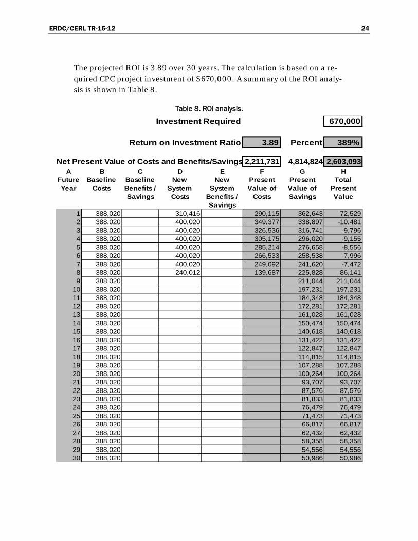
The projected ROI is 3.89 over 30 years. The calculation is based on a re-quired CPC project investment of $670,000. A summary of the ROI analy-sis is shown in Table 8.
Table 8. ROI analysis.
670,000
3.89 Percent 389%
2,211,731 4,814,824 2,603,093A B C D E F G H
Future Year
Baseline Costs
Baseline Benefits / Savings
New System Costs
New System
Benefits / Savings
Present Value of
Costs
Present Value of Savings
Total Present Value
1 388,020 310,416 290,115 362,643 72,5292 388,020 400,020 349,377 338,897 -10,4813 388,020 400,020 326,536 316,741 -9,7964 388,020 400,020 305,175 296,020 -9,1555 388,020 400,020 285,214 276,658 -8,5566 388,020 400,020 266,533 258,538 -7,9967 388,020 400,020 249,092 241,620 -7,4728 388,020 240,012 139,687 225,828 86,1419 388,020 211,044 211,044
10 388,020 197,231 197,23111 388,020 184,348 184,34812 388,020 172,281 172,28113 388,020 161,028 161,02814 388,020 150,474 150,47415 388,020 140,618 140,61816 388,020 131,422 131,42217 388,020 122,847 122,84718 388,020 114,815 114,81519 388,020 107,288 107,28820 388,020 100,264 100,26421 388,020 93,707 93,70722 388,020 87,576 87,57623 388,020 81,833 81,83324 388,020 76,479 76,47925 388,020 71,473 71,47326 388,020 66,817 66,81727 388,020 62,432 62,43228 388,020 58,358 58,35829 388,020 54,556 54,55630 388,020 50,986 50,986
Investment Required
Return on Investment Ratio
Net Present Value of Costs and Benefits/Savings

ERDC/CERL TR-15-12 25
5 Conclusions and Recommendations
5.1 Conclusions
In corrosive environments, copper far outperforms aluminum and steel. The coating systems tested did not serve to protect these alternate metals sufficiently to make those coated alternative metals competitive with bare copper. The work also demonstrated that corrosion of copper will be de-layed by the application of a coating system. While the tests of the coated copper coupons were not continued until failure, it was seen that the ap-plication of a coating to the copper parts doubled the time until the onset of significant corrosion and metal loss. A doubling of the performance life would easily justify the added cost of a coating system.
Highly corrosive environments like Hawaii create a problem for DoD facil-ities and vehicles. Coatings like phenolic, Blygold, and E-coat provide a method to mitigate corrosion and extend the service life of DoD assets like HVAC condensers. However, the application methods for Blygold and E-Coat show advantages over the dip or flow-coat methods used to apply phenolic coatings. This study validates that any coating provides a level of corrosion protection that is cost beneficial to the service life of HVAC con-densers. Additionally, the protected fins of the condenser allow the unit to maintain efficient heat transfer and to reduce the strain on mechanical components. The sample coupons with phenolic and E-coat (Coating E) in this experiment exhibited less blistering and coating failures than the Blygold coating. Over a 30-year period, it was calculated that the ROI ratio of coating HVAC condensers in Hawaii was 3.89.
5.2 Recommendations
Based on the accelerated weathering data, it is recommended that conden-sers in corrosive environments be manufactured with copper coils and fins that are coated. The data does not identify any coating as being superior on copper, so it is suggested the manufacturer’s standard coating system be accepted.
It is recommended that the HVAC condensers and on-site coupons under this test be periodically revisited over the next 30 years, and the corrosion-protection performance of the two coating technologies be re-evaluated.

ERDC/CERL TR-15-12 26
Additional inspections will provide additional data to more accurately predict the life cycle of each coating used in this application.
5.2.1 Applicability
This work’s finding are applicable for finned-type heat exchangers in ex-tremely corrosive environments. Applicable heat exchangers include con-densers used in AC applications as well as other heat recovery and dissipa-tion applications that employ lightweight heat-transfer surfaces. Guidance documents typically contain a note to the designer suggesting that the pro-ject location be researched to determine the environmental effects on finned tube coils and providing options. Where the environmental effects are severe, the option of using factory-coated copper fins should be en-couraged.
5.2.2 Implementation
Guidance documents should be revised to provide guidance for selecting coated copper condenser coils and fins in highly corrosive environments. The following documents should be revised:
• In Federal Specification OO-A-374C (DoD 2011) edit the third sentence in Paragraph 6.1.10, to read as follows:
“In coastal areas, condenser should be made of copper tube and copper
fins and coated with the manufacturer’s standard coating. Copper items
should be insulated for protection against galvanic corrosion from fer-
rous metal parts.”
• In UFGS 23 64 00.00 10 (DoD 2008), add the following to the end of the Note in Paragraph 2.6:
“Copper tubes with copper fins coated with the manufacturer’s standard
coating should be specified for the most severely corrosive locations.”
• In UFGS 23 81 00.00 20 (DoD 2009): o Paragraph 2.2.8 a—add the following sentence to the NOTE: “Cop-
per tubes with copper fins coated with the manufacturer’s standard coating should be specified for the most severely corrosive loca-tions.”

ERDC/CERL TR-15-12 27
o Paragraph 2.3.2—add the following sentence to the NOTE: “Copper tubes with copper fins coated with the manufacturer’s standard coating should be specified for the most severely corrosive loca-tions.”
o Paragraph 2.4.7—add the following sentence to the NOTE: “Copper tubes with copper fins coated with the manufacturer’s standard coating should be specified for the most severely corrosive loca-tions.”
o Paragraph 2.6—add the following sentence to the second NOTE: “Copper tubes with copper fins coated with the manufacturer’s standard coating should be specified for the most severely corrosive locations.”

ERDC/CERL TR-15-12 28
References ASTM. 2009. “Standard Test Method for Evaluating Degree of Blistering of Paints.”
ASTM D714. West Conshohocken, PA: ASTM International.
______. 2010. “Standard Practice for Cyclic Salt Fog/UV Exposure of Painted Metal, (Alternating Exposures in a Fog/Dry Cabinet and a UV/Condensation Cabinet).” ASTM D5894. West Conshohocken, PA: ASTM International.
______. 2012. “Standard Test Method for Evaluating Degree of Rusting on Painted Steel Surfaces.” ASTM D610. West Conshohocken, PA: ASTM International.
DoD (Department of Defense). 2008. “Heating, Ventilating, and Air Conditioning: Water Chillers, Vapor Compression Type.” UFGS 23 64 00.00 10. Prepared by Naval Facilities Command. Washington, DC: Department of Defense.
______. 2009. “Heating, Ventilating, and Air Conditioning: Unitary Air Conditioning Equipment.” UFGS 23 81 00.00 20. Prepared by Naval Facilities Command. Washington, DC: Department of Defense.
______. 2011. “Air Conditioners with Remote Condensing Units or Remote Air-Cooled and Water-Cooled Condenser Units, Unitary.” Federal Specifications (FED SPEC) OO-A-374C. Washington, DC: Department of Defense.
Herzber, Eric F., Amelia Kelly, and Norman T. O’Meara. 2010. The Annual Cost of Corrosion for the Department of Defense Facilities and Infrastructure: 2007–2008 Update. Report DL907T2. Tysons, VA: LMI.
Meister, John J. 2000. Polymer Modification Principles, Techniques and Applications. Boca Raton, FL: CRC Press
OMB (Office of Management and Budget). 1994 Guidelines and Discount Rates for Benefit-Cost Analysis of Federal Programs. OMB Circular No. A-95. Washington, DC: Office of Management and Budget.

ERDC/CERL TR-15-12 29
Appendix: Annual Assessment, Photo Documentation
Photos of test coupons were made before the project period began (time zero). Then, on-site visual assessments of coupons and fins coated with each of the two subject coating technologies occurred at approximately 12 and 24 months after installation. In addition, on-site coupons with phe-nolic coating and on-site bare coupons were also assessed at the same time periods.
Photographic documentation of the state of all coupons was recorded dur-ing each visual inspection. These photos are arranged by coating and elapsed time. Coating E comparisons are shown in Figures A1–A3 (Rack 1), Figures A13–A15 (Rack 2) and Figures A26–28 (condenser fins). Coat-ing B comparisons are shown in Figures A4–A6 (Rack 1), Figures A16–A18 (Rack 2) and Figures A29–A31 (condenser fins). Phenolic coating compar-isons are shown in Figures A7–A9 (Rack 1) and Figures A19–A21 (Rack 2). Bare coupon comparisons are shown in Figures A10–A12 (Rack 1) and Figures A22–A25 (Rack 2).
For convenience, the key to codes painted on the coupons and shown in the figures that follow is provided again in this appendix (Table A1).
Table A1. Explanation of coupon codes and numbers.
Code Location/Reference Abbreviation Meaning
First alpha character = BASE MATERIAL
A Aluminum
C Copper
S Steel
Second alpha character = COATING
E Coating E (ElectroFin)
B Coating B (Bygold)
P Phenolic coating
R Bare (no coating)
Third character (numeric) = RACK NUMBER
1 Rack 1
2 Rack 2

ERDC/CERL TR-15-12 30
Coating E comparisons (Rack 1)
Figure A1. Rack 1, Coating E coupons at time zero.
Figure A2. Rack 1, Coating E coupons at 12 months.
Figure A3. Rack 1, Coating E coupons at 24 months.

ERDC/CERL TR-15-12 31
Coating B comparisons (Rack 1)
Figure A4. Rack 1, Coating B coupons at time zero.
Figure A5. Rack 1, Coating B coupons at 12 months.
Figure A6. Rack 1, Coating B coupons at 24 months.

ERDC/CERL TR-15-12 32
Phenolic-coated coupon comparisons (Rack 1)
Figure A7. Rack 1, phenolic-coated coupons at time zero.
Figure A8. Rack 1, phenolic-coated coupons at 12 months.
Figure A9. Rack 1, phenolic-coated coupons at 24 months.

ERDC/CERL TR-15-12 33
Bare coupon comparisons (Rack 1)
Figure A10. Rack 1, bare coupons at time zero.
Figure A11. Rack 1, bare coupons at 12 months.
Figure A12. Rack 1, bare coupons at 24 months.

ERDC/CERL TR-15-12 34
Coating E coupon comparisons (Rack 2)
Figure A13. Rack 2, Coating E coupons at time zero.
Figure A14. Rack 2, Coating E coupons at 12 months.
Figure A15. Rack 2, Coating E coupons at 24 months.

ERDC/CERL TR-15-12 35
Coating B coupon comparisons (Rack 2)
Figure A16. Rack 2, Coating B coupons at time zero.
Figure A17. Rack 2, Coating B coupons at 12 months.
Figure A18. Rack 2, Coating B coupons at 24 months.

ERDC/CERL TR-15-12 36
Phenolic-coated coupon comparisons (Rack 2)
Figure A19. Rack 2, phenolic-coated coupons at time zero.
Figure A20. Rack 2, phenolic-coated coupons at 12 months.
Figure A21. Rack 2, phenolic-coated coupons at 24 months.

ERDC/CERL TR-15-12 37
Bare coupon comparisons (Rack 2)
A22. Rack 2, bare coupons at time zero.
A 23. Rack 2, bare coupons at 12 months.
(see next page)

ERDC/CERL TR-15-12 38
Figure A24. Rack 2, bare coupons at 24 months. Note that aluminum coupon (at far left) has become detached.
Figure A25. Rack 2, bare coupons at 24 months (photo 2). Note that this photo was taken after aluminum coupon was repositioned.

ERDC/CERL TR-15-12 39
Coating E: condenser fin comparisons
Figure A26. Coating E condenser fins at time zero.
Figure A27. Coating E condenser fins at 12 months.

ERDC/CERL TR-15-12 40
Figure A28. Coating E condenser fins at 24 months.
Coating B: condenser fin comparisons
Figure A29. Coating B condenser fins at time zero.
ERDC/CERL TR-15-12 41
Figure A30. Coating B condenser fins at 12 months.
Figure A31. Coating B condenser fins at 24 months.

REPORT DOCUMENTATION PAGE Form Approved
OMB No. 0704-0188 Public reporting burden for this collection of information is estimated to average 1 hour per response, including the time for reviewing instructions, searching existing data sources, gathering and maintaining the data needed, and completing and reviewing this collection of information. Send comments regarding this burden estimate or any other aspect of this collection of information, including suggestions for reducing this burden to Department of Defense, Washington Headquarters Services, Directorate for Information Operations and Reports (0704-0188), 1215 Jefferson Davis Highway, Suite 1204, Arlington, VA 22202-4302. Respondents should be aware that notwithstanding any other provision of law, no person shall be subject to any penalty for failing to comply with a collection of information if it does not display a currently valid OMB control number. PLEASE DO NOT RETURN YOUR FORM TO THE ABOVE ADDRESS. 1. REPORT DATE (DD-MM-YYYY)
June 2015 2. REPORT TYPE
Final 3. DATES COVERED (From - To)
4. TITLE AND SUBTITLE
Demonstration of Corrosion-Resistant Coatings for Air-Conditioning Coils and Fins: Final Report on Project F10-AR01
5a. CONTRACT NUMBER
5b. GRANT NUMBER
5c. PROGRAM ELEMENT NUMBER Corrosion Prevention and Control
6. AUTHOR(S) Alfred D. Beitelman and Susan A Drozdz
5d. PROJECT NUMBER F10-AR01
5e. TASK NUMBER
5f. WORK UNIT NUMBER
7. PERFORMING ORGANIZATION NAME(S) AND ADDRESS(ES) US Army Engineer Research and Development Center Construction Engineering Research Laboratory P.O. Box 9005 Champaign, IL 61826-9005
8. PERFORMING ORGANIZATION REPORT NUMBER
ERDC/CERL TR-15-12
9. SPONSORING / MONITORING AGENCY NAME(S) AND ADDRESS(ES) Office of the Secretary of Defense (OUSD(AT&L)) 3090 Defense Pentagon Washington, DC 20301-3090
10. SPONSOR/MONITOR’S ACRONYM(S) OSD
11. SPONSOR/MONITOR’S REPORT NUMBER(S)
12. DISTRIBUTION / AVAILABILITY STATEMENT Approved for public release; distribution is unlimited.
13. SUPPLEMENTARY NOTES
14. ABSTRACT
Department of Defense military installations operate air-conditioning equipment in humid and coastal locations that produce high levels of corrosion. Installation experience has shown that severe corrosion has reduced expected equipment life cycles by up to 50%. This project for the Office of the Secretary of Defense Corrosion Prevention and Control Program demonstrated and evaluated the performance characteristics of two corrosion prevention coatings on condenser coils in highly corrosive environ-ments. This work assessed the capabilities and advantages of an aluminum-impregnated polyurethane coating and a flexible epoxy polymer applied to two separate condenser units at Schofield Barracks, Hawaii. The work also included fabricating and exposing test coupons of various substrates, each coated with the two coating systems and a third coating commonly used in less-corrosive environments. These coupons were exposed both at the Schofield Barracks site and in a laboratory-accelerated expo-sure cabinet. The work recommends that copper rather than aluminum components be specified in air conditioners operating in highly corrosive environments. A copper substrate protected with a newer type of corrosion coating is projected to extend the equipment’s expected life cycle from 7–10 years to 25–30 years. The return on investment for the project is 3.89.
15. SUBJECT TERMS corrosion prevention, coatings, HVAC condenser coils, evaluation, performance testing, Schofield Barracks, HI
16. SECURITY CLASSIFICATION OF: 17. LIMITATION OF ABSTRACT
18. NUMBER OF PAGES
19a. NAME OF RESPONSIBLE PERSON
a. REPORT
Unclassified
b. ABSTRACT
Unclassified
c. THIS PAGE
Unclassified UU 52 19b. TELEPHONE NUMBER (include area code)
Standard Form 298 (Rev. 8-98) Prescribed by ANSI Std. 239.18