ERDC/CERL TR-05-36, Military Requirements for JP … · ERDC/ CERL TR-05-36 Military Requirements...
59
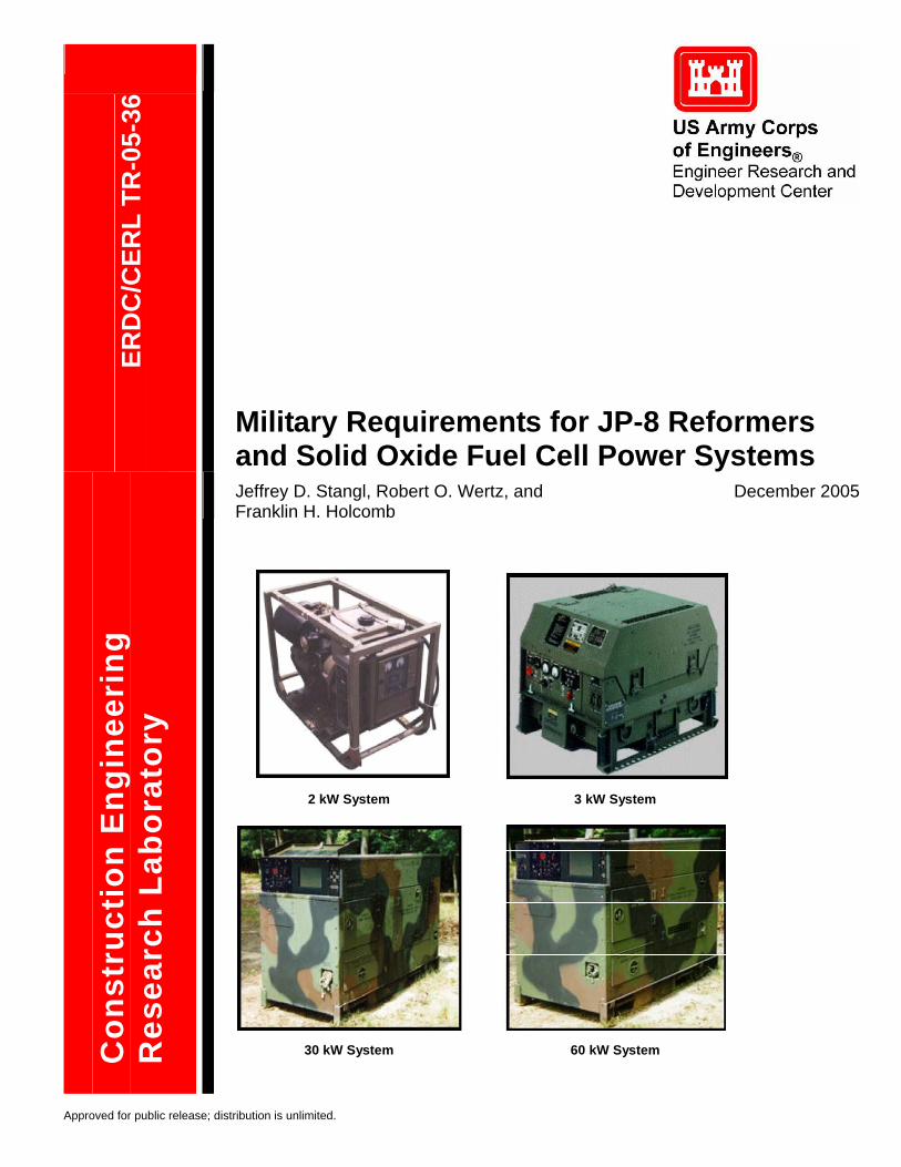
ERDC/CERL TR-05-36 Military Requirements for JP-8 Reformers and Solid Oxide Fuel Cell Power Systems Jeffrey D. Stangl, Robert O. Wertz, and Franklin H. Holcomb December 2005 Construction Engineering Research Laboratory Approved for public release; distribution is unlimited. 2 kW System 3 kW System 30 kW System 60 kW System
-
Upload
hoangtuyen -
Category
Documents
-
view
221 -
download
0
Transcript of ERDC/CERL TR-05-36, Military Requirements for JP … · ERDC/ CERL TR-05-36 Military Requirements...
ERD
C/C
ERL
TR-0
5-36
Military Requirements for JP-8 Reformers and Solid Oxide Fuel Cell Power Systems Jeffrey D. Stangl, Robert O. Wertz, and Franklin H. Holcomb
December 2005
Con
stru
ctio
n E
ngin
eeri
ng
Res
earc
h La
bora
tory
Approved for public release; distribution is unlimited.
2 kW System 3 kW System
30 kW System 60 kW System
ERDC/CERL TR-05-36December 2005
Military Requirements for JP-8 Reformers and Solid Oxide Fuel Cell Power Systems Franklin H. Holcomb Construction Engineering Research Laboratory PO Box 9005 Champaign, IL 61826-9005
Jeffery Stangl and Robert Wertz Concurrent Technologies Corporation Johnstown, PA
Final Report Approved for public release; distribution is unlimited.
Prepared for U.S. Army Corps of Engineers Washington, DC 20314-1000
Under Work Unit No. BF707G
ii ERDC/CERL TR-05-36
ABSTRACT: This work represents an early step in the military Solid Oxide Fuel Cell (SOFC) development process. This study identifies: (1) the military’s current and future electric power needs and capabilities, (2) the requirements for building a military SOFC power system with design recommendations, and (3) an initial approach to a Modularization Plan for developing military SOFC technology. The goals of this Modularization Plan will be to minimize procurement, training, and maintenance costs.
Existing generators will be replaced with future electric power systems requiring reduced weight and footprint. Fuel efficiency goals will reduce fuel tanker fleet size and further decrease the logistical footprint. Military Standards, Specifications, and Handbooks pertaining specifically to SOFCs are not available, nor planned. This report identifies documents pertinent to the development of solid oxide fuel cell systems (<60 kW) based on information gathered through assessments of current applications and procurement requirements for military electric power. The report offers design recommendations to minimize the procurement cost of the SOFC system. The report discusses current capabilities, provides high-level considerations for a modularization plan, and identifies potential benefits of adopting a modular approach to SOFC systems, which is anticipated to reduce training, streamline the maintenance requirements, and reduce logistics.
DISCLAIMER: The contents of this report are not to be used for advertising, publication, or promotional purposes. Citation of trade names does not constitute an official endorsement or approval of the use of such commercial products. All product names and trademarks cited are the property of their respective owners. The findings of this report are not to be construed as an official Department of the Army position unless so designated by other authorized documents.
DESTROY THIS REPORT WHEN IT IS NO LONGER NEEDED. DO NOT RETURN IT TO THE ORIGINATOR.
ERDC/CERL TR-05-36 iii
Contents
List of Figures and Tables ............................................................................................................... v
Conversion Factors........................................................................................................................ vii
Preface............................................................................................................................................. viii
1 Introduction ................................................................................................................................ 1 Background......................................................................................................................... 1 Objective............................................................................................................................. 2 Approach ............................................................................................................................ 3 Mode of Technology Transfer ............................................................................................. 3
2 Research Approach................................................................................................................... 4 Site Visits ............................................................................................................................ 4 Informational Documents.................................................................................................... 6 PM-MEP Documents .......................................................................................................... 6
3 Existing Military Electric Power Systems............................................................................... 8 Applications ........................................................................................................................ 8 Characteristics .................................................................................................................... 9
4 Future Military Electric Power Systems................................................................................13 Applications ...................................................................................................................... 13 Requirements ................................................................................................................... 14
Military Specifications, Standards, and Handbooks ..................................................................... 14 Physical Characteristics .............................................................................................................. 16 Performance Characteristics ....................................................................................................... 17 Fuels, Lubricants, and USEPA Compliance................................................................................. 17 Voltage and Frequency Output Characteristics ........................................................................... 17 Operational and Safety Features................................................................................................. 19 Environmental Requirements ...................................................................................................... 20 Daily Operational Profiles ............................................................................................................ 23 Program Cost .............................................................................................................................. 24 System Training Concept............................................................................................................. 25
iv ERDC/CERL TR-05-36
5 Design Considerations and Recommendations .................................................................26 Design Considerations...................................................................................................... 26
Water Availability ......................................................................................................................... 26 Sulfur Content in Military Fuels.................................................................................................... 26 Diesel Fuel and NATO F-34 (JP-8) Additives............................................................................... 27
Design Recommendations................................................................................................ 31 Minimum Stack Voltage ............................................................................................................... 31 Operator Interface ....................................................................................................................... 31 Preventive Maintenance Checks and Services............................................................................ 32 Control System............................................................................................................................ 32 Improved Efficiency ..................................................................................................................... 32
6 Modularization..........................................................................................................................33 Capabilities Assessment................................................................................................... 33 Modularization Approach .................................................................................................. 34 Modularization Considerations ......................................................................................... 34 Modularization Benefits .................................................................................................... 35 Reduction of Training and Maintenance Requirements ................................................... 36
7 Conclusions..............................................................................................................................37
References.......................................................................................................................................39
Acronyms and Abbreviations .......................................................................................................40
Appendix A: Federal and Military Specifications ......................................................................42
Appendix B: Federal and Military Standards .............................................................................45
Appendix C: Military Handbooks and Field Manuals................................................................48
Report Documentation Page.........................................................................................................50
ERDC/CERL TR-05-36 v
List of Figures and Tables
Figures
1 Information flow........................................................................................................... 4 2 Electrical power systems (2 and 3 kW)..................................................................... 10 3 Electrical power systems (5, 10, and 15 kW)............................................................ 11 4 Electrical power systems (30 and 60 kW)................................................................. 12
Tables
1 Warner-Robins Air Logistics Center ............................................................................ 5 2 Fort Belvoir meeting .................................................................................................... 5 3 Informational documents............................................................................................. 6 4 Documents obtained from the PM-MEP...................................................................... 6 5 Current DOD electrical power system inventory ......................................................... 8 6 Applications of mobile/tactical electrical power........................................................... 9 7 Characteristics and capabilities 2 and 3 kW systems................................................. 9 8 Characteristics and capabilities of 5, 10, and 15 kW systems.................................. 10 9 System characteristics and capabilities of 30 kW and 60 kW TQGs ........................ 11 10 Applications of mobile/tactical electrical power......................................................... 14 11 Federal and military specifications ............................................................................ 15 12 Federal and military standards.................................................................................. 16 13 Military handbooks .................................................................................................... 16 14 Physical characteristics defined by the TEP-ORD.................................................... 17 15 Performance characteristics defined by the TEP-ORD............................................. 18 16 Electrical output characteristics................................................................................. 19 17 Environmental requirements ..................................................................................... 21 18 Twenty-four hour operational profile during stationary days ..................................... 23 19 Twenty-four hour operational profile during movement days.................................... 23 20 Fifteen-day wartime mission profile tasks ................................................................. 24 21 Electrical program cost estimate 2009 through 2019 power class ........................... 24 22 Static dissipater composition, composition/ingredient information............................ 28
vi ERDC/CERL TR-05-36
23 Corrosion inhibitor composition, composition/ingredient information........................ 29 24 DC inverter input voltage vs. generator output voltage............................................. 31 25 Total Army generator requirement quantities power class ........................................ 33 26 Army requirement per year power class ................................................................... 33
ERDC/CERL TR-05-36 vii
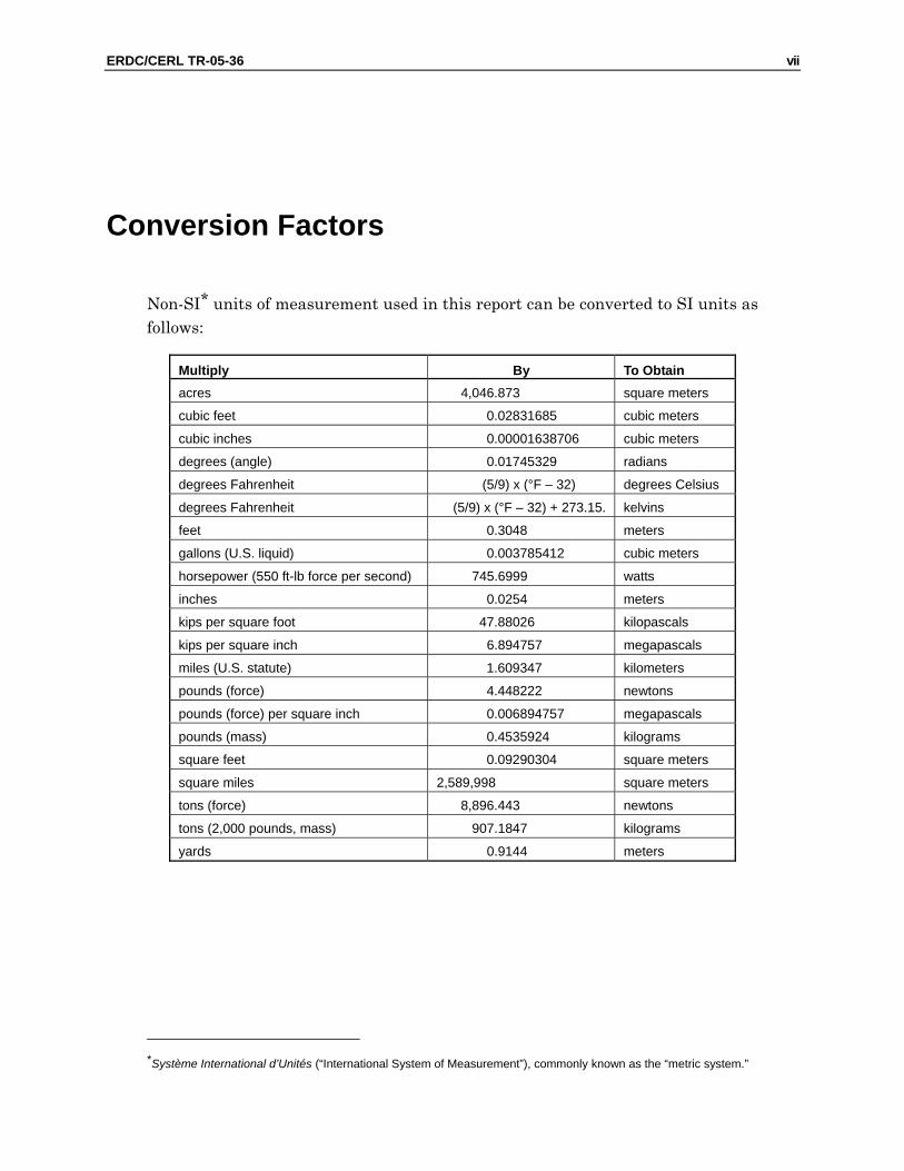
Conversion Factors
Non-SI* units of measurement used in this report can be converted to SI units as follows:
Multiply By To Obtain acres 4,046.873 square meters
cubic feet 0.02831685 cubic meters
cubic inches 0.00001638706 cubic meters
degrees (angle) 0.01745329 radians
degrees Fahrenheit (5/9) x (°F – 32) degrees Celsius
degrees Fahrenheit (5/9) x (°F – 32) + 273.15. kelvins
feet 0.3048 meters
gallons (U.S. liquid) 0.003785412 cubic meters
horsepower (550 ft-lb force per second) 745.6999 watts
inches 0.0254 meters
kips per square foot 47.88026 kilopascals
kips per square inch 6.894757 megapascals
miles (U.S. statute) 1.609347 kilometers
pounds (force) 4.448222 newtons
pounds (force) per square inch 0.006894757 megapascals
pounds (mass) 0.4535924 kilograms
square feet 0.09290304 square meters
square miles 2,589,998 square meters
tons (force) 8,896.443 newtons
tons (2,000 pounds, mass) 907.1847 kilograms
yards 0.9144 meters
*Système International d’Unités (“International System of Measurement”), commonly known as the “metric system.”
viii ERDC/CERL TR-05-36
Preface
This study was conducted under project “Solid Oxide Fuel Cells (SOFCs)”; Work Unit No. BF707G. The technical monitor was Mr. Bob Boyd, Office of the Director, Defense, Research, and Engineering (ODDR&E).
The work was performed by the Energy Branch (CF-E), of the Facilities Division (CF), Construction Engineering Research Laboratory (CERL). The CERL Principal Investigator was Franklin H. Holcomb. Part of this work was done by Jeffery Stangl and Robert Wertz, Concurrent Technologies Corporation (CTC), Johnstown, PA under Contract Number: DACA42-02-2-001. The technical editor was William J. Wolfe, Information Technology Laboratory. Dr. Thomas Hartranft is Chief, CEERD-CF-E, and L. Michael Golish is Chief, CEERD-CF. The associated Techni-cal Director was Gary W. Schanche, CEERD-CVT. The Acting Director of CERL is Dr. Ilker R. Adiguzel.
CERL is an element of the U.S. Army Engineer Research and Development Center (ERDC), U.S. Army Corps of Engineers. The Commander and Executive Director of ERDC is COL James R. Rowan, and the Director of ERDC is Dr. James R. Houston.
ERDC/CERL TR-05-36 1
1 Introduction
Background
Electric power, provided primarily by mobile generator sets in the combat zone, is the lifeblood of the Armed Forces.*
The Department of Defense (DOD) makes significant use of Mobile Electric Power (MEP) generators operated from logistic fuels in the range of 2 kW to 60 kW. These systems account for 100,691 individual units with a combined generating capacity of 1,037,725 kW. However, additional units of the current design will not be available from manufacturers after 2008 because they do not comply with future U.S. Envi-ronmental Protection Agency (USEPA) requirements. While the military can con-tinue to use existing units, these units will eventually become unsupportable as manufacturers discontinue production and support for the units. Moreover, the DOD has developed goals for a new generation of USEPA-compliant logistic fuels powered MEP generators that will perform better than the current generation of MEP systems. These goals include reduced weight and acoustic signature; and im-proved fuel consumption, reliability, and repair time. While these goals may be met by combustion based units, Solid Oxide Fuel Cell (SOFC) based MEP systems are also a potential alternative.
The U.S. Department of Energy (DOE) Solid State Energy Conversion Alliance (SECA) program is a collaborative effort between the Federal Government, inde-pendent research organizations, U.S. industry, and academia, the ultimate goal of which is to develop low-cost, remote/stationary, SOFC power systems in the 3 kW to 10 kW range. Currently, the SECA program has a long time frame for SOFC devel-opment and does not address the DOD’s technology development needs regarding fuel and environmental operating requirements. While SECA’s low-cost solution may be ideal for some applications, the military has a great and immediate need for remote sources of cost and energy efficient power with reduced environmental emis-sions and decreased logistical burdens. Contributing to this need is the fact that
* DOD Program Manager Mobile Electric Power (PM-MEP) web site, accessible through URL:
http://peocscss.tacom.army.mil/pmMEP.html
2 ERDC/CERL TR-05-36
some aging power systems in the field will become increasingly difficult to maintain as industry ceases to support systems that are judged inefficient by today’s stan-dards.
Consequently, there is a need for the “militarization” of SECA-based SOFC technol-ogy in the near-term with the following characteristics. The fuel cell power systems must be: • modular in design • able to operate within the range of readily available defense logistic fuels and
provide stable, continuous power • rugged enough to be carried into the field, set up, and operated unattended • capable of generating 3 kW to 10 kW of power • energy efficient and able to meet the guidelines for environmental emissions
and logistical burden reductions.
Researchers at the U.S. Army Engineer Research and Development Center, Con-struction Engineering Research Lab (ERDC-CERL) have actively participated in the development and application of advanced fuel cell technology since the early 1990s. In that time, the Department of Defense (DOD) has installed the largest fleet of fuel cells in the world. Because the DOD need for power systems with the above charac-teristics is more urgent than the current SECA time frame, ERDC-CERL has part-nered with Concurrent Technologies Corporation (CTC), the Gas Technology Insti-tute (GTI), and the Air Force Research Laboratory (AFRL) to: • develop the necessary SOFC technologies to permit the utilization of defense
logistic fuels including the assembly and testing of prototype fuel processing devices
• research and document the technical specifications for military applications • gather information on performance requirements and use this information to
drive the system design and development • assemble and test prototype SOFC units.
This initial stage of research was required to develop military requirements for a SOFC power system that will address DOD needs.
Objective
This objectives of this work, which represents a first step in the development of military SOFC technologies, were to:
1. Identify the military’s current and future electric power needs and capabilities 2. Identify the current and new requirements for mobile electric power systems and
make design recommendations for building a military SOFC power system.
ERDC/CERL TR-05-36 3
Approach
This work derived existing military electric power systems characteristics, future military electric power systems requirements, design considerations and recom-mendations, and a potential modularization plan from site visits, interviews, and (paper document and WWW) literature searches. Specifically, the research team:
1. Visited several DOD facilities and reviewed relevant documents i.e., military regulations, standards, specifications, etc. (Chapter 2)
2. Reviewed existing military electric power systems and military applications within each power class from 2 through 60 kW (Chapter 3)
3. Identified future military electric power systems, applications, and requirements based on information from PM-MEP and the Tactical Electrical Power Opera-tional Requirements Document (TEP ORD) (Chapter 4)
4. Identified and provided design considerations to be addressed in the early design stage of a SOFC power system (Chapter 5)
5. Reviewed current mobile electrical power capabilities, provided high-level consid-erations for a modularization plan, and identified several potential benefits of a modularization plan (Chapter 6)
6. Identified an initial approach to a Modularization Plan for developing military SOFC technology that will minimize procurement, training, and maintenance costs.
Mode of Technology Transfer
It is anticipated that the information developed in this stage of work will support the CERL program to design, develop, and fabricate a military SOFC Power Plant up to 10 kW for military applications, which will include military diesel and JP-8 fuel reforming. The information in this report will be transmitted directly to the sponsor of this work, and will also be made accessible through the World Wide Web (WWW) at URLs:
http://www.cecer.army.mil (ERDC-CERL website) http://www.dodfuelcell.com (DOD Fuel Cell Demonstration website).
4 ERDC/CERL TR-05-36
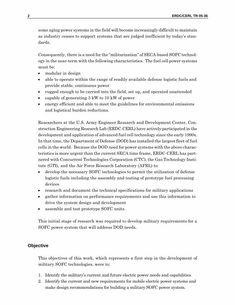
2 Research Approach Figure 1 illustrates the methodology used here to identify requirements, and to de-velop the capabilities summary and modularization plan. Military requirements were derived from interviews, technology reviews, literature searches, and follow-on analyses. Although an in-depth search of the www.assist.daps.dla.mil web site for SOFC Military Standards, Specifications, and Handbooks yielded no directly related documents, MEP information was readily available on various DOD Web sites. This information was supplemented with direct contact with user groups and procure-ment agencies.
Site Visits
Five on-site fact-gathering meetings were held at two installations to help identify military requirements. Meeting discussions included overviews of CTC, the DOD’s Fuel Cell Test and Evaluation Center (FCTec) operated by CTC, and the SOFC de-velopment project.
Figure 1. Information flow.
ERDC/CERL TR-05-36 5
The MEP Tactical Quiet Generator (TQG) current capabilities were discussed with personnel at Warner Robins Air Logistic Center (WR-ALC) during the 3 June 2004 meeting. It was found that the end users and logistic centers do not have records of the total TQG capability. (The WR-ALC maintains records of the capabilities for the MEP within their command.) The PM-MEP procures and maintains records of the total MEP capability; TQGs are now being replaced by smaller, quieter, more efficient Tactical Electric Power (TEP). This information formed the basis for dis-cussions with additional personnel of the PM-MEP (Table 1).
The primary focus of the meeting with PM-MEP personnel (Table 2) was to identify the military requirements. Secondary discussions focused on current and future MEP capabilities. The PM-MEP confirmed that TQGs are going to be replaced by TEP starting approximately 2007. The “TEP ORD, Advanced Medium-Sized Mobile Power System (AMMPS) Purchase Description,” and “PM-MEP Master Plan” were discussed, and found to be useful sources of information to help identify the military requirements for future electrical power systems.
Table 1. Warner-Robins Air Logistics Center.
Meeting No. Contact 1 Marianne Deuster, Division Chief 1 Barbara Schlafer, Branch Chief-Vehicles 1 Doug Foster, Branch Chief-Generators 2 Bill Likos, A2PT2O 3 Don Maycroft, Bear Base 4 Lisa Hosecloth, Program Manager for Generators 4 Tahrea Grant, Engineer 4 Nhat Nguyen, Lead Engineer 4 Gene Moss, Equipment Specialist
Table 2. Fort Belvoir meeting.
Meeting No. Contact 5 Dr. James Cross, Deputy Program Manager 5 Kelly Alexander, Chief Engineer PM-MEP2 5 Paul Shively , Chief-Power Generation Branch 5 Walter Taschek, Fuel Cell Technology Team Consultant
6 ERDC/CERL TR-05-36
Informational Documents
In-depth searches on the World Wide Web and meetings yielded several sources of information (Table 3).
Table 3. Informational documents.
Number Document Source 1 Standard Family of Mobile Electric Power Generating Sources www.pm-mep.army.mil 2 2 kW Military Tactical Generator Sets www.pm-mep.army.mil 3 3 kW Tactical Quiet Generator Sets www.pm-mep.army.mil 4 5 kW Tactical Quiet Generator Sets www.pm-mep.army.mil 5 10 kW Tactical Quiet Generator Sets www.pm-mep.army.mil 6 15 kW Tactical Quiet Generator Sets www.pm-mep.army.mil 7 30 kW Tactical Quiet Generator Sets www.pm-mep.army.mil 8 60 kW Tactical Quiet Generator Sets www.pm-mep.army.mil 9 Military Standard, Specifications, and Handbooks www.assist.daps.dla.mil
10 PM-MEP Master Plan 2001 PM-MEP 11 Purchase Description Advanced Medium Sized Mobile Power
Sources PM-MEP
12 Tactical Electrical Power Operational Requirements Documents (TEP ORD)
PM-MEP
13 Advanced Power Generation Systems for the 21st Century: Mar-ket Survey and Recommendations for a Design Philosophy
Oak Ridge National Laboratory
PM-MEP Documents
Table 4 lists the documents obtained from the PM-MEP to support this study.
Table 4. Documents obtained from the PM-MEP.
No. Document Source 1 PM-MEP Master Plan 2001 PM-MEP
2 Purchase Description Generator Sets, Skid Mounted, Trailer Mounted Advanced Medium Sized Mobile Power Sources, Tactical
PM-MEP
3 Tactical Electrical Power Operational Requirements Documents PM-MEP
The PM-MEP Master Plan 2001 provides PM-MEP’s plan for attaining goals and how the vision will positively affect the U.S. Armed Forces. The primary focus reaps the benefits of standardization, which include: reduced number of configura-tions, reduced total operating costs, consolidated annual procurements, improved readiness, enhanced operation, maintenance and training, commonality of compo-nents, reduced number of operator and maintenance manuals, increased reliability, survivability, deployability, supportability, and warfighting effectiveness.
The document Purchase Description Generator Sets, Skid Mounted, Trailer Mounted Advanced Medium Sized Mobile Power Sources, Tactical provides general require-

ERDC/CERL TR-05-36 7
ments for generator sets that are 5 through 60 kW, 50/60 and 400 hertz, skid mounted, trailer mounted, tactical, quiet, alternating current, and diesel fuel driven.
The document Tactical Electrical Power Operational Requirements describes the op-erational capability, threat, shortcomings of existing systems, capabilities, program support, force structure, schedule considerations, and program affordability.
8 ERDC/CERL TR-05-36
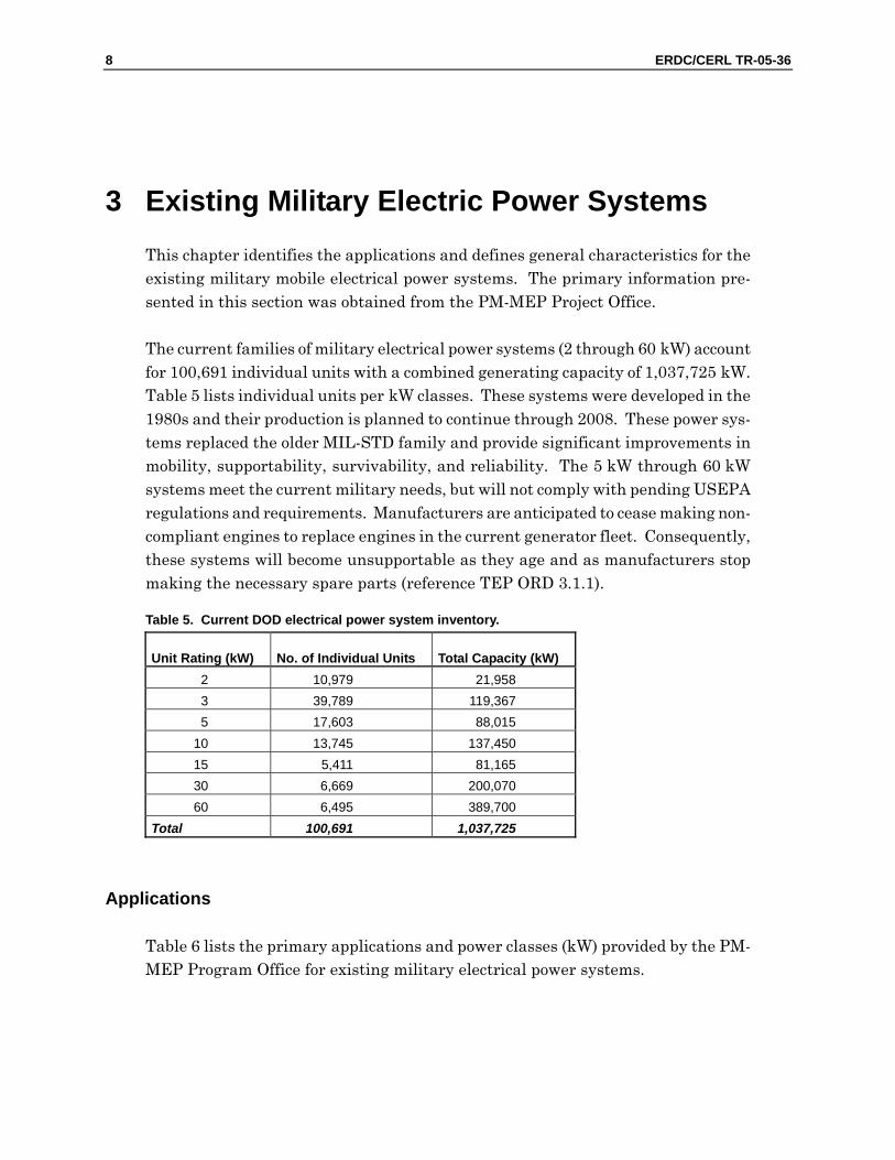
3 Existing Military Electric Power Systems This chapter identifies the applications and defines general characteristics for the existing military mobile electrical power systems. The primary information pre-sented in this section was obtained from the PM-MEP Project Office.
The current families of military electrical power systems (2 through 60 kW) account for 100,691 individual units with a combined generating capacity of 1,037,725 kW. Table 5 lists individual units per kW classes. These systems were developed in the 1980s and their production is planned to continue through 2008. These power sys-tems replaced the older MIL-STD family and provide significant improvements in mobility, supportability, survivability, and reliability. The 5 kW through 60 kW systems meet the current military needs, but will not comply with pending USEPA regulations and requirements. Manufacturers are anticipated to cease making non-compliant engines to replace engines in the current generator fleet. Consequently, these systems will become unsupportable as they age and as manufacturers stop making the necessary spare parts (reference TEP ORD 3.1.1).
Table 5. Current DOD electrical power system inventory.
Unit Rating (kW) No. of Individual Units Total Capacity (kW) 2 10,979 21,958 3 39,789 119,367 5 17,603 88,015
10 13,745 137,450 15 5,411 81,165 30 6,669 200,070 60 6,495 389,700
Total 100,691 1,037,725
Applications
Table 6 lists the primary applications and power classes (kW) provided by the PM-MEP Program Office for existing military electrical power systems.
ERDC/CERL TR-05-36 9
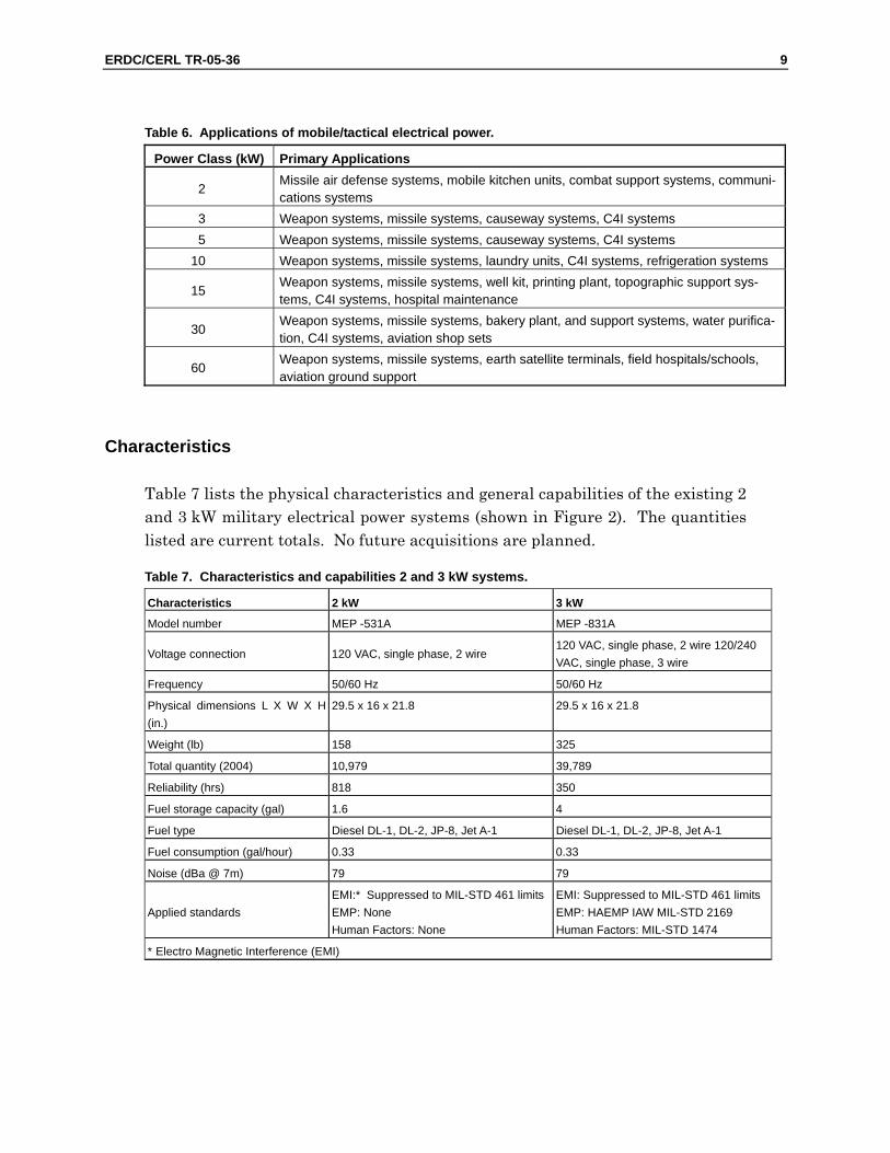
Table 6. Applications of mobile/tactical electrical power.
Power Class (kW) Primary Applications
2 Missile air defense systems, mobile kitchen units, combat support systems, communi-cations systems
3 Weapon systems, missile systems, causeway systems, C4I systems 5 Weapon systems, missile systems, causeway systems, C4I systems
10 Weapon systems, missile systems, laundry units, C4I systems, refrigeration systems
15 Weapon systems, missile systems, well kit, printing plant, topographic support sys-tems, C4I systems, hospital maintenance
30 Weapon systems, missile systems, bakery plant, and support systems, water purifica-tion, C4I systems, aviation shop sets
60 Weapon systems, missile systems, earth satellite terminals, field hospitals/schools, aviation ground support
Characteristics
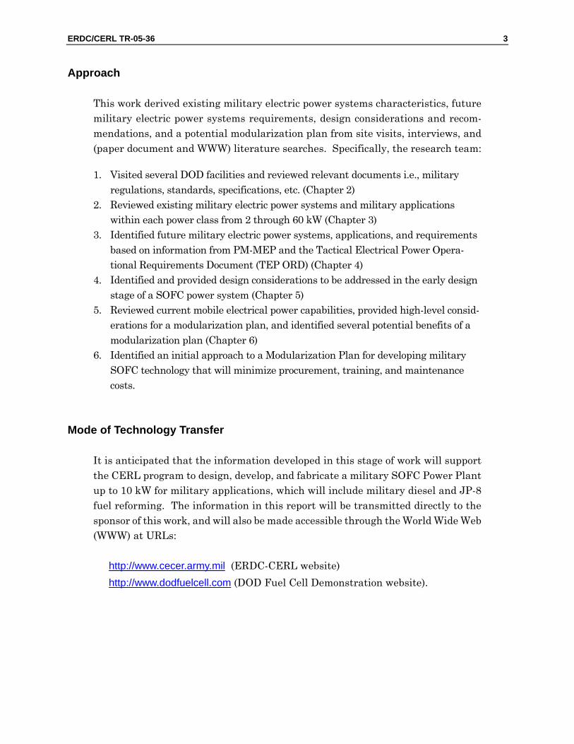
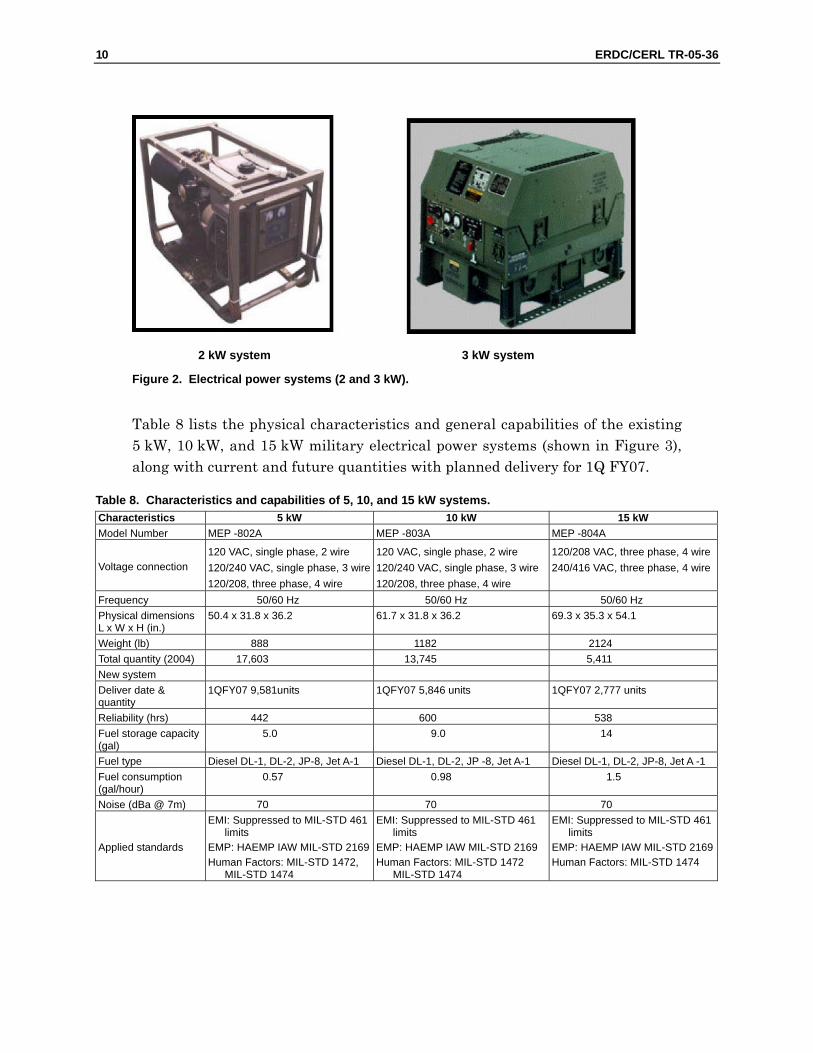
Table 7 lists the physical characteristics and general capabilities of the existing 2 and 3 kW military electrical power systems (shown in Figure 2). The quantities listed are current totals. No future acquisitions are planned.
Table 7. Characteristics and capabilities 2 and 3 kW systems.
Characteristics 2 kW 3 kW
Model number MEP -531A MEP -831A
Voltage connection 120 VAC, single phase, 2 wire 120 VAC, single phase, 2 wire 120/240 VAC, single phase, 3 wire
Frequency 50/60 Hz 50/60 Hz
Physical dimensions L X W X H (in.)
29.5 x 16 x 21.8 29.5 x 16 x 21.8
Weight (lb) 158 325
Total quantity (2004) 10,979 39,789
Reliability (hrs) 818 350
Fuel storage capacity (gal) 1.6 4
Fuel type Diesel DL-1, DL-2, JP-8, Jet A-1 Diesel DL-1, DL-2, JP-8, Jet A-1
Fuel consumption (gal/hour) 0.33 0.33
Noise (dBa @ 7m) 79 79
Applied standards EMI:* Suppressed to MIL-STD 461 limits EMP: None Human Factors: None
EMI: Suppressed to MIL-STD 461 limitsEMP: HAEMP IAW MIL-STD 2169 Human Factors: MIL-STD 1474
* Electro Magnetic Interference (EMI)
10 ERDC/CERL TR-05-36
2 kW system 3 kW system
Figure 2. Electrical power systems (2 and 3 kW).
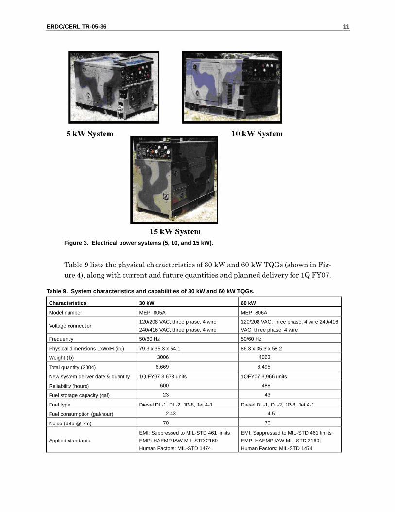
Table 8 lists the physical characteristics and general capabilities of the existing 5 kW, 10 kW, and 15 kW military electrical power systems (shown in Figure 3), along with current and future quantities with planned delivery for 1Q FY07.
Table 8. Characteristics and capabilities of 5, 10, and 15 kW systems. Characteristics 5 kW 10 kW 15 kW Model Number MEP -802A MEP -803A MEP -804A
Voltage connection 120 VAC, single phase, 2 wire 120/240 VAC, single phase, 3 wire 120/208, three phase, 4 wire
120 VAC, single phase, 2 wire 120/240 VAC, single phase, 3 wire120/208, three phase, 4 wire
120/208 VAC, three phase, 4 wire 240/416 VAC, three phase, 4 wire
Frequency 50/60 Hz 50/60 Hz 50/60 Hz Physical dimensions L x W x H (in.)
50.4 x 31.8 x 36.2 61.7 x 31.8 x 36.2 69.3 x 35.3 x 54.1
Weight (lb) 888 1182 2124 Total quantity (2004) 17,603 13,745 5,411 New system Deliver date & quantity
1QFY07 9,581units 1QFY07 5,846 units 1QFY07 2,777 units
Reliability (hrs) 442 600 538 Fuel storage capacity (gal)
5.0 9.0 14
Fuel type Diesel DL-1, DL-2, JP-8, Jet A-1 Diesel DL-1, DL-2, JP -8, Jet A-1 Diesel DL-1, DL-2, JP-8, Jet A -1 Fuel consumption (gal/hour)
0.57 0.98 1.5
Noise (dBa @ 7m) 70 70 70
Applied standards
EMI: Suppressed to MIL-STD 461 limits
EMP: HAEMP IAW MIL-STD 2169 Human Factors: MIL-STD 1472,
MIL-STD 1474
EMI: Suppressed to MIL-STD 461 limits
EMP: HAEMP IAW MIL-STD 2169 Human Factors: MIL-STD 1472
MIL-STD 1474
EMI: Suppressed to MIL-STD 461 limits
EMP: HAEMP IAW MIL-STD 2169Human Factors: MIL-STD 1474
ERDC/CERL TR-05-36 11
Figure 3. Electrical power systems (5, 10, and 15 kW).
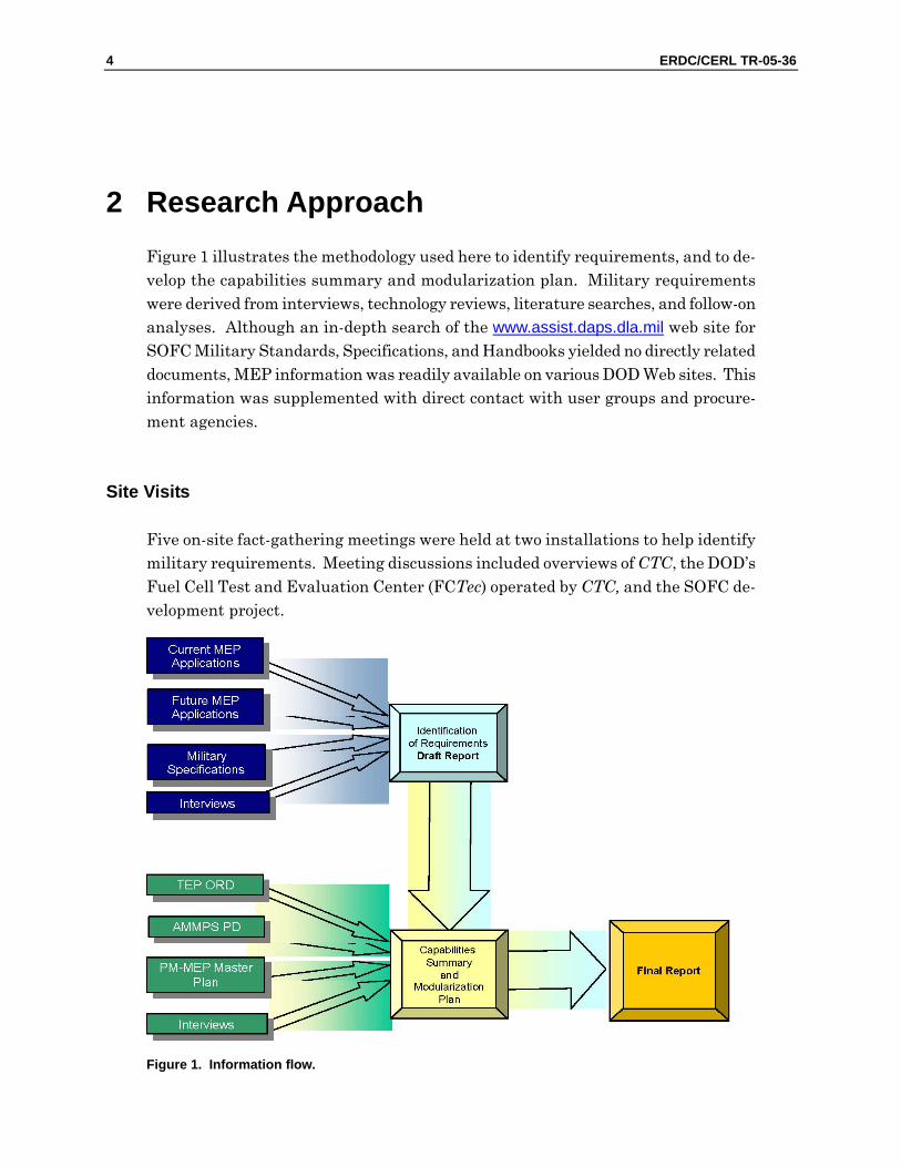
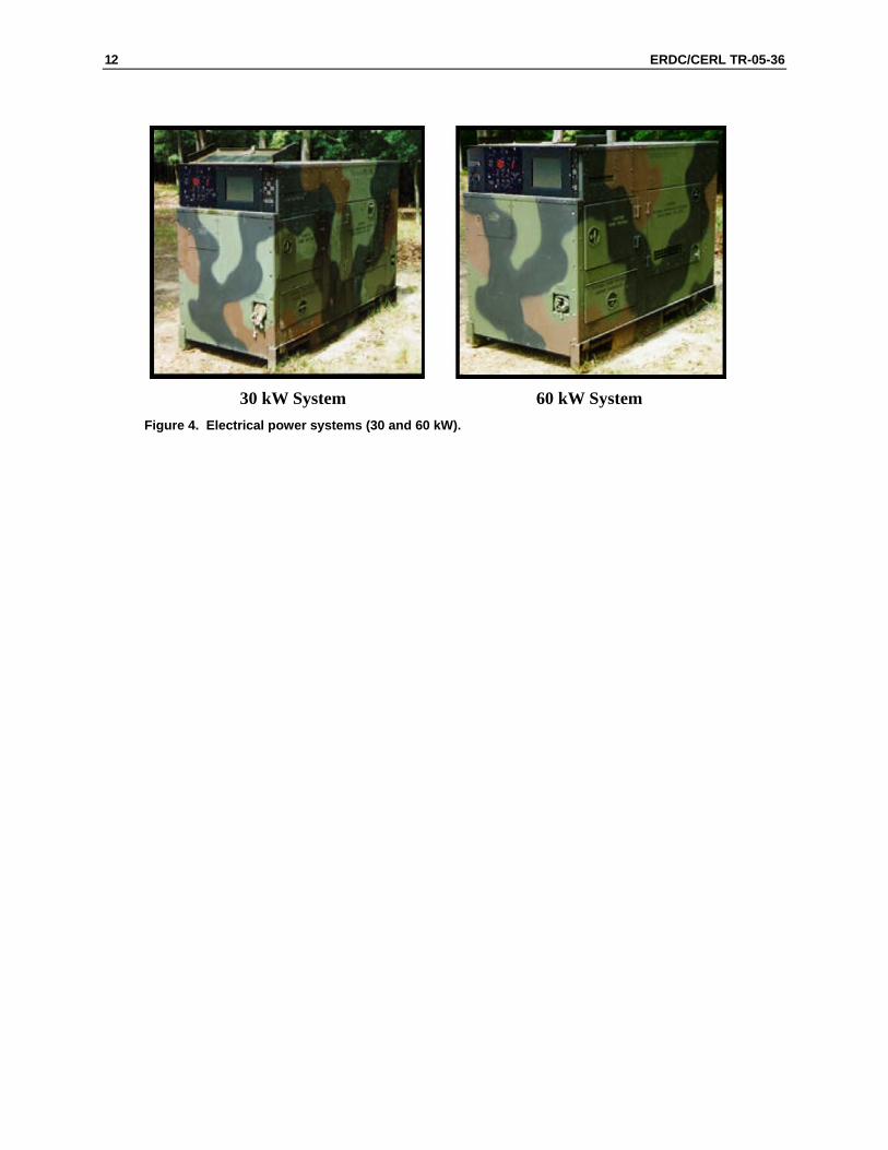
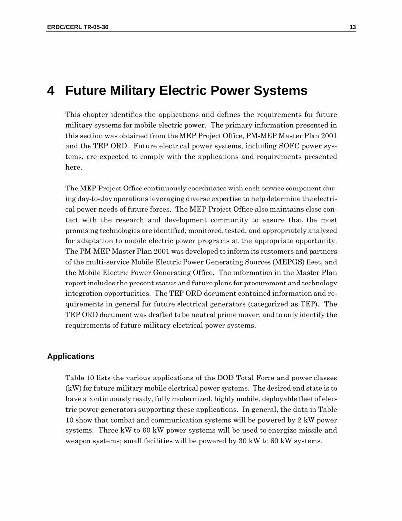
Table 9 lists the physical characteristics of 30 kW and 60 kW TQGs (shown in Fig-ure 4), along with current and future quantities and planned delivery for 1Q FY07.
Table 9. System characteristics and capabilities of 30 kW and 60 kW TQGs.
Characteristics 30 kW 60 kW
Model number MEP -805A MEP -806A
Voltage connection 120/208 VAC, three phase, 4 wire 240/416 VAC, three phase, 4 wire
120/208 VAC, three phase, 4 wire 240/416 VAC, three phase, 4 wire
Frequency 50/60 Hz 50/60 Hz
Physical dimensions LxWxH (in.) 79.3 x 35.3 x 54.1 86.3 x 35.3 x 58.2
Weight (lb) 3006 4063
Total quantity (2004) 6,669 6,495
New system deliver date & quantity 1Q FY07 3,678 units 1QFY07 3,966 units
Reliability (hours) 600 488
Fuel storage capacity (gal) 23 43
Fuel type Diesel DL-1, DL-2, JP-8, Jet A-1 Diesel DL-1, DL-2, JP-8, Jet A-1
Fuel consumption (gal/hour) 2.43 4.51
Noise (dBa @ 7m) 70 70
Applied standards EMI: Suppressed to MIL-STD 461 limits EMP: HAEMP IAW MIL-STD 2169 Human Factors: MIL-STD 1474
EMI: Suppressed to MIL-STD 461 limits EMP: HAEMP IAW MIL-STD 2169| Human Factors: MIL-STD 1474
12 ERDC/CERL TR-05-36
30 kW System 60 kW System
Figure 4. Electrical power systems (30 and 60 kW).
ERDC/CERL TR-05-36 13
4 Future Military Electric Power Systems This chapter identifies the applications and defines the requirements for future military systems for mobile electric power. The primary information presented in this section was obtained from the MEP Project Office, PM-MEP Master Plan 2001 and the TEP ORD. Future electrical power systems, including SOFC power sys-tems, are expected to comply with the applications and requirements presented here.
The MEP Project Office continuously coordinates with each service component dur-ing day-to-day operations leveraging diverse expertise to help determine the electri-cal power needs of future forces. The MEP Project Office also maintains close con-tact with the research and development community to ensure that the most promising technologies are identified, monitored, tested, and appropriately analyzed for adaptation to mobile electric power programs at the appropriate opportunity. The PM-MEP Master Plan 2001 was developed to inform its customers and partners of the multi-service Mobile Electric Power Generating Sources (MEPGS) fleet, and the Mobile Electric Power Generating Office. The information in the Master Plan report includes the present status and future plans for procurement and technology integration opportunities. The TEP ORD document contained information and re-quirements in general for future electrical generators (categorized as TEP). The TEP ORD document was drafted to be neutral prime mover, and to only identify the requirements of future military electrical power systems.
Applications
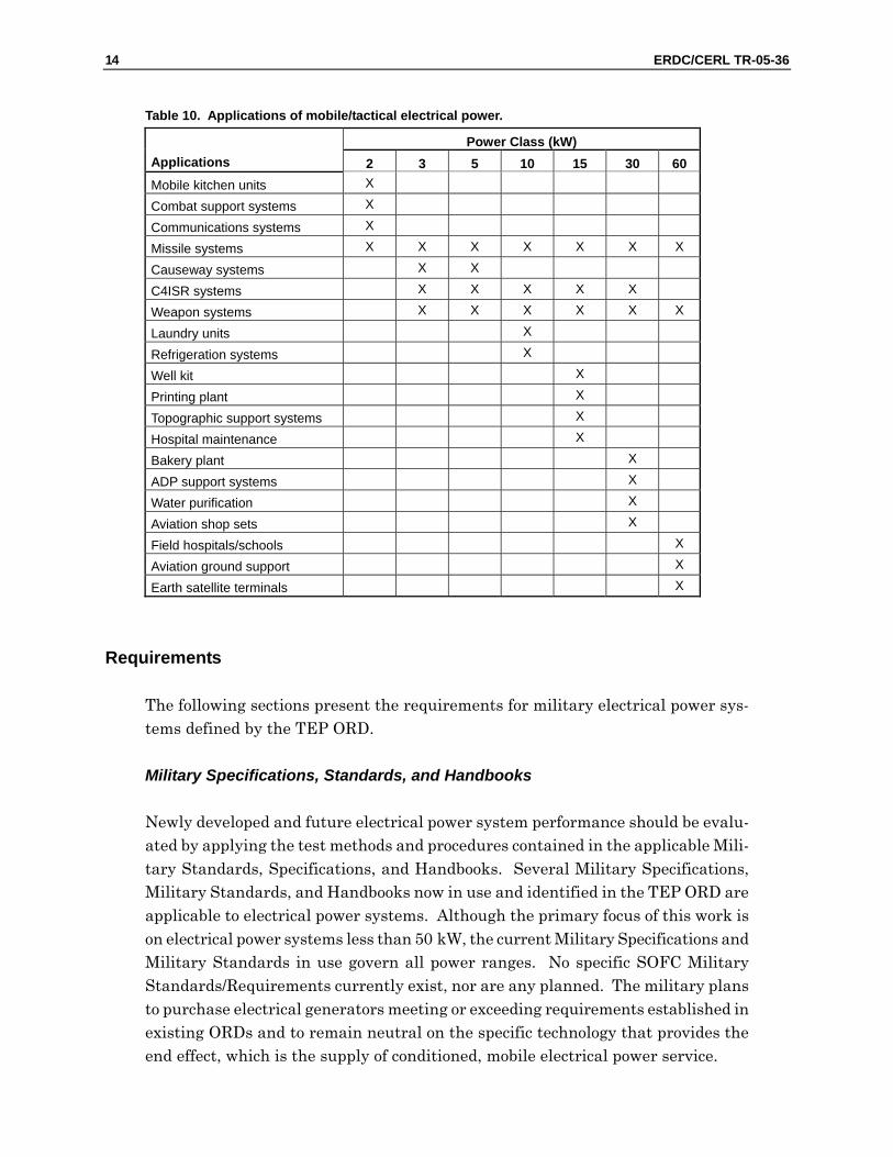
Table 10 lists the various applications of the DOD Total Force and power classes (kW) for future military mobile electrical power systems. The desired end state is to have a continuously ready, fully modernized, highly mobile, deployable fleet of elec-tric power generators supporting these applications. In general, the data in Table 10 show that combat and communication systems will be powered by 2 kW power systems. Three kW to 60 kW power systems will be used to energize missile and weapon systems; small facilities will be powered by 30 kW to 60 kW systems.
14 ERDC/CERL TR-05-36
Table 10. Applications of mobile/tactical electrical power.
Power Class (kW) Applications 2 3 5 10 15 30 60 Mobile kitchen units X
Combat support systems X
Communications systems X
Missile systems X X X X X X X
Causeway systems X X
C4ISR systems X X X X X
Weapon systems X X X X X X
Laundry units X
Refrigeration systems X
Well kit X
Printing plant X
Topographic support systems X
Hospital maintenance X
Bakery plant X
ADP support systems X
Water purification X
Aviation shop sets X
Field hospitals/schools X
Aviation ground support X
Earth satellite terminals X
Requirements
The following sections present the requirements for military electrical power sys-tems defined by the TEP ORD.
Military Specifications, Standards, and Handbooks
Newly developed and future electrical power system performance should be evalu-ated by applying the test methods and procedures contained in the applicable Mili-tary Standards, Specifications, and Handbooks. Several Military Specifications, Military Standards, and Handbooks now in use and identified in the TEP ORD are applicable to electrical power systems. Although the primary focus of this work is on electrical power systems less than 50 kW, the current Military Specifications and Military Standards in use govern all power ranges. No specific SOFC Military Standards/Requirements currently exist, nor are any planned. The military plans to purchase electrical generators meeting or exceeding requirements established in existing ORDs and to remain neutral on the specific technology that provides the end effect, which is the supply of conditioned, mobile electrical power service.
ERDC/CERL TR-05-36 15
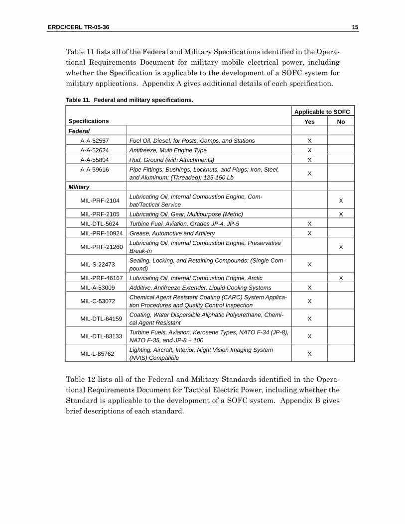
Table 11 lists all of the Federal and Military Specifications identified in the Opera-tional Requirements Document for military mobile electrical power, including whether the Specification is applicable to the development of a SOFC system for military applications. Appendix A gives additional details of each specification.
Table 11. Federal and military specifications.
Applicable to SOFC Specifications Yes No Federal A-A-52557 Fuel Oil, Diesel; for Posts, Camps, and Stations X A-A-52624 Antifreeze, Multi Engine Type X A-A-55804 Rod, Ground (with Attachments) X A-A-59616 Pipe Fittings: Bushings, Locknuts, and Plugs; Iron, Steel,
and Aluminum; (Threaded); 125-150 Lb X
Military
MIL-PRF-2104 Lubricating Oil, Internal Combustion Engine, Com-bat/Tactical Service
X
MIL-PRF-2105 Lubricating Oil, Gear, Multipurpose (Metric) X MIL-DTL-5624 Turbine Fuel, Aviation, Grades JP-4, JP-5 X MIL-PRF-10924 Grease, Automotive and Artillery X
MIL-PRF-21260 Lubricating Oil, Internal Combustion Engine, Preservative Break-In
X
MIL-S-22473 Sealing, Locking, and Retaining Compounds: (Single Com-pound)
X
MIL-PRF-46167 Lubricating Oil, Internal Combustion Engine, Arctic X MIL-A-53009 Additive, Antifreeze Extender, Liquid Cooling Systems X
MIL-C-53072 Chemical Agent Resistant Coating (CARC) System Applica-tion Procedures and Quality Control Inspection
X
MIL-DTL-64159 Coating, Water Dispersible Aliphatic Polyurethane, Chemi-cal Agent Resistant
X
MIL-DTL-83133 Turbine Fuels, Aviation, Kerosene Types, NATO F-34 (JP-8), NATO F-35, and JP-8 + 100
X
MIL-L-85762 Lighting, Aircraft, Interior, Night Vision Imaging System (NVIS) Compatible
X
Table 12 lists all of the Federal and Military Standards identified in the Opera-tional Requirements Document for Tactical Electric Power, including whether the Standard is applicable to the development of a SOFC system. Appendix B gives brief descriptions of each standard.
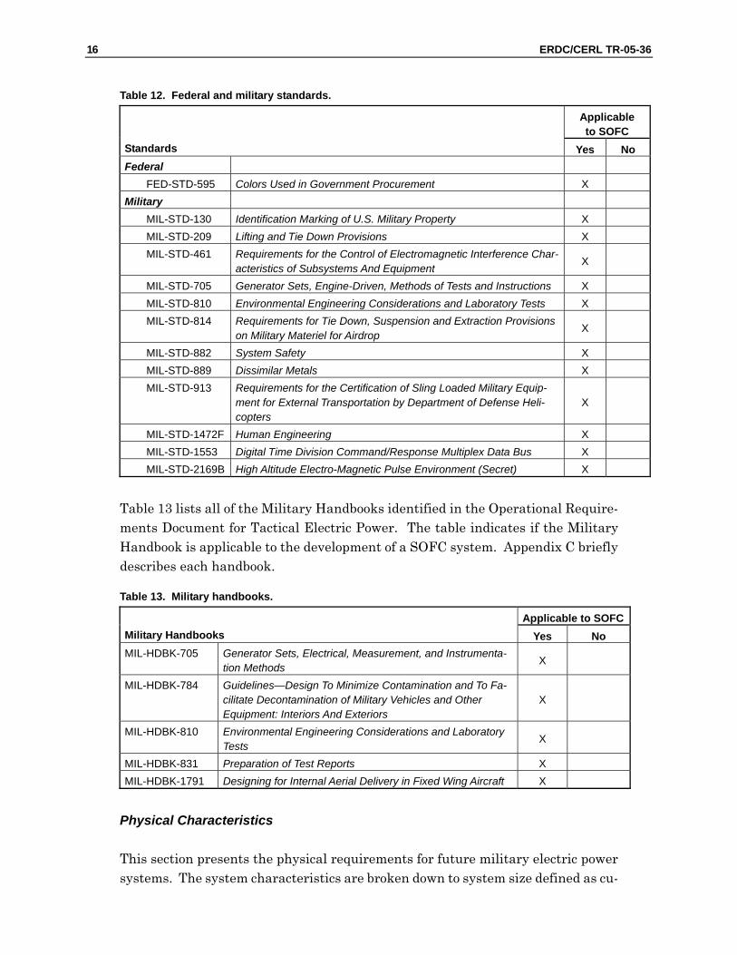
16 ERDC/CERL TR-05-36
Table 12. Federal and military standards.
Applicable to SOFC
Standards Yes No Federal FED-STD-595 Colors Used in Government Procurement X Military MIL-STD-130 Identification Marking of U.S. Military Property X MIL-STD-209 Lifting and Tie Down Provisions X MIL-STD-461 Requirements for the Control of Electromagnetic Interference Char-
acteristics of Subsystems And Equipment X
MIL-STD-705 Generator Sets, Engine-Driven, Methods of Tests and Instructions X MIL-STD-810 Environmental Engineering Considerations and Laboratory Tests X MIL-STD-814 Requirements for Tie Down, Suspension and Extraction Provisions
on Military Materiel for Airdrop X
MIL-STD-882 System Safety X MIL-STD-889 Dissimilar Metals X MIL-STD-913 Requirements for the Certification of Sling Loaded Military Equip-
ment for External Transportation by Department of Defense Heli-copters
X
MIL-STD-1472F Human Engineering X MIL-STD-1553 Digital Time Division Command/Response Multiplex Data Bus X MIL-STD-2169B High Altitude Electro-Magnetic Pulse Environment (Secret) X
Table 13 lists all of the Military Handbooks identified in the Operational Require-ments Document for Tactical Electric Power. The table indicates if the Military Handbook is applicable to the development of a SOFC system. Appendix C briefly describes each handbook.
Table 13. Military handbooks.
Applicable to SOFC Military Handbooks Yes No MIL-HDBK-705 Generator Sets, Electrical, Measurement, and Instrumenta-
tion Methods X
MIL-HDBK-784 Guidelines—Design To Minimize Contamination and To Fa-cilitate Decontamination of Military Vehicles and Other Equipment: Interiors And Exteriors
X
MIL-HDBK-810 Environmental Engineering Considerations and Laboratory Tests
X
MIL-HDBK-831 Preparation of Test Reports X MIL-HDBK-1791 Designing for Internal Aerial Delivery in Fixed Wing Aircraft X
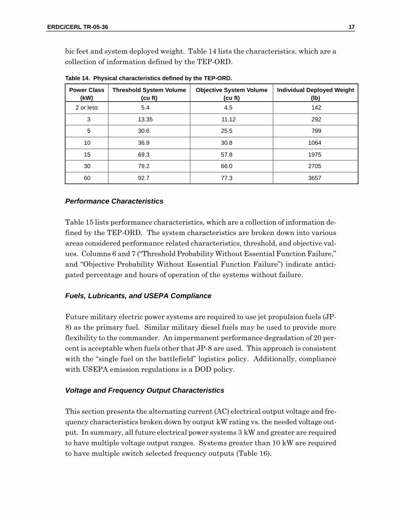
Physical Characteristics
This section presents the physical requirements for future military electric power systems. The system characteristics are broken down to system size defined as cu-
ERDC/CERL TR-05-36
Power Class (kW)
Threshold System Volume(cu ft)
Objective System Volume(cu ft)
Individual Deployed Weight(lb)
2 or less 5.4 4.5 142
3 13.35 11.12 292
5 30.6 25.5 799
10 36.9 30.8 1064
15 69.3 57.8 1975
30 79.2 66.0 2705
60 92.7 77.3 3657
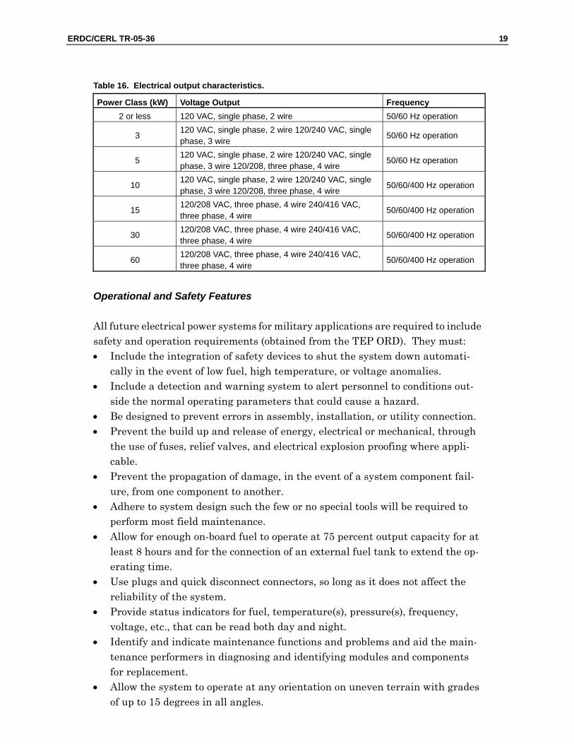
This section presents the alternating current (AC) electrical output voltage and fre-quency characteristics broken down by output kW rating vs. the needed voltage out-put. In summary, all future electrical power systems 3 kW and greater are required to have multiple voltage output ranges. Systems greater than 10 kW are required to have multiple switch selected frequency outputs (Table 16).
Voltage and Frequency Output Characteristics
Future military electric power systems are required to use jet propulsion fuels (JP-8) as the primary fuel. Similar military diesel fuels may be used to provide more flexibility to the commander. An impermanent performance degradation of 20 per-cent is acceptable when fuels other that JP-8 are used. This approach is consistent with the “single fuel on the battlefield” logistics policy. Additionally, compliance with USEPA emission regulations is a DOD policy.
Fuels, Lubricants, and USEPA Compliance
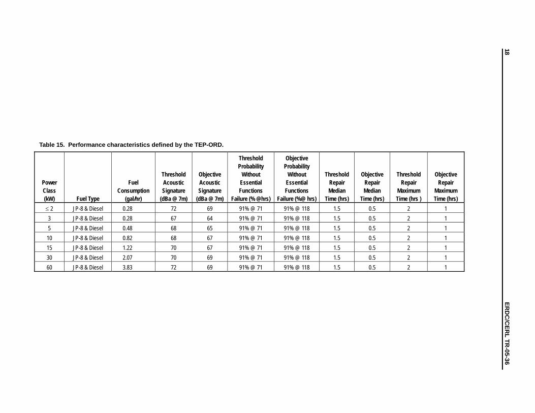
Table 15 lists performance characteristics, which are a collection of information de-fined by the TEP-ORD. The system characteristics are broken down into various areas considered performance related characteristics, threshold, and objective val-ues. Columns 6 and 7 (“Threshold Probability Without Essential Function Failure,” and “Objective Probability Without Essential Function Failure”) indicate antici-pated percentage and hours of operation of the systems without failure.
Performance Characteristics
Table 14. Physical characteristics defined by the TEP-ORD.
bic feet and system deployed weight. Table 14 lists the characteristics, which are a collection of information defined by the TEP-ORD.
17
18 ER
DC
/CER
L TR-05-36
Power Class (kW) Fuel Type
Fuel Consumption
(gal/hr)
Threshold Acoustic Signature
(dBa @ 7m)
Objective Acoustic Signature
(dBa @ 7m)
Threshold Probability
Without Essential Functions
Failure (% @hrs)
Objective Probability
Without Essential Functions
Failure (%@ hrs)
Threshold Repair Median
Time (hrs)
Objective Repair Median
Time (hrs)
Threshold Repair
Maximum Time (hrs )
Objective Repair
Maximum Time (hrs)
≤ 2 JP-8 & Diesel 0.28 72 69 91% @ 71 91% @ 118 1.5 0.5 2 1 3 JP-8 & Diesel 0.28 67 64 91% @ 71 91% @ 118 1.5 0.5 2 1 5 JP-8 & Diesel 0.48 68 65 91% @ 71 91% @ 118 1.5 0.5 2 1 10 JP-8 & Diesel 0.82 68 67 91% @ 71 91% @ 118 1.5 0.5 2 1 15 JP-8 & Diesel 1.22 70 67 91% @ 71 91% @ 118 1.5 0.5 2 1 30 JP-8 & Diesel 2.07 70 69 91% @ 71 91% @ 118 1.5 0.5 2 1 60 JP-8 & Diesel 3.83 72 69 91% @ 71 91% @ 118 1.5 0.5 2 1
Table 15. Performance characteristics defined by the TEP-ORD.
ERDC/CERL TR-05-36 19
Table 16. Electrical output characteristics.
Power Class (kW) Voltage Output Frequency 2 or less 120 VAC, single phase, 2 wire 50/60 Hz operation
3 120 VAC, single phase, 2 wire 120/240 VAC, single phase, 3 wire
50/60 Hz operation
5 120 VAC, single phase, 2 wire 120/240 VAC, single phase, 3 wire 120/208, three phase, 4 wire
50/60 Hz operation
10 120 VAC, single phase, 2 wire 120/240 VAC, single phase, 3 wire 120/208, three phase, 4 wire
50/60/400 Hz operation
15 120/208 VAC, three phase, 4 wire 240/416 VAC, three phase, 4 wire
50/60/400 Hz operation
30 120/208 VAC, three phase, 4 wire 240/416 VAC, three phase, 4 wire
50/60/400 Hz operation
60 120/208 VAC, three phase, 4 wire 240/416 VAC, three phase, 4 wire
50/60/400 Hz operation
Operational and Safety Features
All future electrical power systems for military applications are required to include safety and operation requirements (obtained from the TEP ORD). They must: • Include the integration of safety devices to shut the system down automati-
cally in the event of low fuel, high temperature, or voltage anomalies. • Include a detection and warning system to alert personnel to conditions out-
side the normal operating parameters that could cause a hazard. • Be designed to prevent errors in assembly, installation, or utility connection. • Prevent the build up and release of energy, electrical or mechanical, through
the use of fuses, relief valves, and electrical explosion proofing where appli-cable.
• Prevent the propagation of damage, in the event of a system component fail-ure, from one component to another.
• Adhere to system design such the few or no special tools will be required to perform most field maintenance.
• Allow for enough on-board fuel to operate at 75 percent output capacity for at least 8 hours and for the connection of an external fuel tank to extend the op-erating time.
• Use plugs and quick disconnect connectors, so long as it does not affect the reliability of the system.
• Provide status indicators for fuel, temperature(s), pressure(s), frequency, voltage, etc., that can be read both day and night.
• Identify and indicate maintenance functions and problems and aid the main-tenance performers in diagnosing and identifying modules and components for replacement.
• Allow the system to operate at any orientation on uneven terrain with grades of up to 15 degrees in all angles.
20 ERDC/CERL TR-05-3
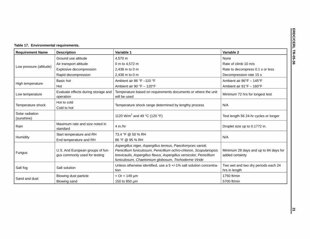
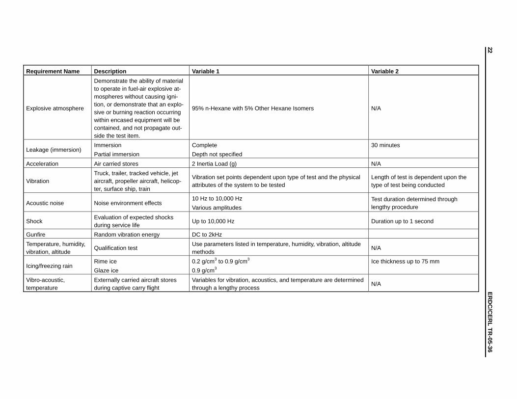
MIL-STD-810 defines procedures for determining and assessing the diverse envi-ronments to which military systems will be exposed during its service life. Table 17 lists the environmental requirements and variables contained within this specifica-tion that are applicable to future military electrical power systems. MIL-STD-810 references additional information on methods developed to support accurate deter-mination of the environmental stresses that equipment will encounter during its service life and to verify corrective actions. Note: the variables listed in Table 17 are “worst case” and do not necessarily apply to all articles being evaluated. Con-siderations for individual articles need to be applied as indicated in MIL-STD-810.
Environmental Requirements
• Allow for the system to operate at full rated load in tropical, temperate, arid and cold climates. The system must also operate at full output at 95 °F and 4,000 ft above sea level, and standard de-rated output at 95 °F and 10,000 ft above sea level.
• Allow for the automatic parallel operation of systems of like size and opera-tional mode for systems 10 kW and larger
• Include a standard NATO slave receptacle, which would allow personnel to connect a military vehicle 24 VDC system to the SOFC system in the event of dead start-up batteries.
• Allow for open-air or warehouse storage. • Start and accept full load within five (5) minutes for all systems excluding
technologies that require lengthy start up times and procedures. • Operate as designed when covered with infrared suppression nets.
6
ER
DC
/
CER
L TR-05-36
Table 17. Environmental requirements.
Requirement Name Description Variable 1 Variable 2
Low pressure (altitude)
Ground use altitude Air transport altitude Explosive decompression Rapid decompression
4,570 m 0 m to 4,572 m 2,438 m to 0 m 2,438 m to 0 m
None Rate of climb 10 m/s Rate to decompress 0.1 s or less Decompression rate 15 s
High temperature Basic hot Hot
Ambient air 86 °F –110 °F Ambient air 90 °F – 120°F
Ambient air 86°F – 145°F Ambient air 91°F – 160°F
Low temperature Evaluate effects during storage and operation
Temperature based on requirements documents or where the unit will be used
Minimum 72 hrs for longest test
Temperature shock Hot to cold Cold to hot
Temperature shock range determined by lengthy process N/A
Solar radiation (sunshine)
1120 W/m2 and 49 °C (120 °F) Test length 56 24-hr cycles or longer
Rain Maximum rate and size noted in standard
4 in./hr Droplet size up to 0.1772 in.
Humidity Start temperature and RH End temperature and RH
73.4 °F @ 50 % RH 86 °F @ 95 % RH
N/A
Fungus U.S. And European groups of fun-gus commonly used for testing
Aspergillus niger, Aspergillus terreus, Paecilomyces varioti, Penicillium funiculosum, Penicillium ochro-chloron, Scopulariopsis brevicaulis, Aspergillus flavus, Aspergillus versicolor, Penicillium funiculosum, Chaetomium globosum, Trichoderme Viride
Minimum 28 days and up to 84 days for added certainty
Salt fog Salt solution Unless otherwise identified, use a 5 +/-1% salt solution concentra-tion
Two wet and two dry periods each 24 hrs in length
Sand and dust Blowing dust particle Blowing sand
< Or = 149 µm 150 to 850 µm
1750 ft/min 5700 ft/min
21
22 ER
DC
/CER
L TR-05-36
Requirement Name Description Variable 1 Variable 2
Explosive atmosphere
Demonstrate the ability of material to operate in fuel-air explosive at-mospheres without causing igni-tion, or demonstrate that an explo-sive or burning reaction occurring within encased equipment will be contained, and not propagate out-side the test item.
95% n-Hexane with 5% Other Hexane Isomers N/A
Leakage (immersion) Immersion Partial immersion
Complete Depth not specified
30 minutes
Acceleration Air carried stores 2 Inertia Load (g) N/A
Vibration Truck, trailer, tracked vehicle, jet aircraft, propeller aircraft, helicop-ter, surface ship, train
Vibration set points dependent upon type of test and the physical attributes of the system to be tested
Length of test is dependent upon the type of test being conducted
Acoustic noise Noise environment effects 10 Hz to 10,000 Hz Various amplitudes
Test duration determined through lengthy procedure
Shock Evaluation of expected shocks during service life
Up to 10,000 Hz Duration up to 1 second
Gunfire Random vibration energy DC to 2kHz Temperature, humidity, vibration, altitude
Qualification test Use parameters listed in temperature, humidity, vibration, altitude methods
N/A
Icing/freezing rain Rime ice Glaze ice
0.2 g/cm3 to 0.9 g/cm3 0.9 g/cm3
Ice thickness up to 75 mm
Vibro-acoustic, temperature
Externally carried aircraft stores during captive carry flight
Variables for vibration, acoustics, and temperature are determined through a lengthy process
N/A
ERDC/CERL TR-05-36 23
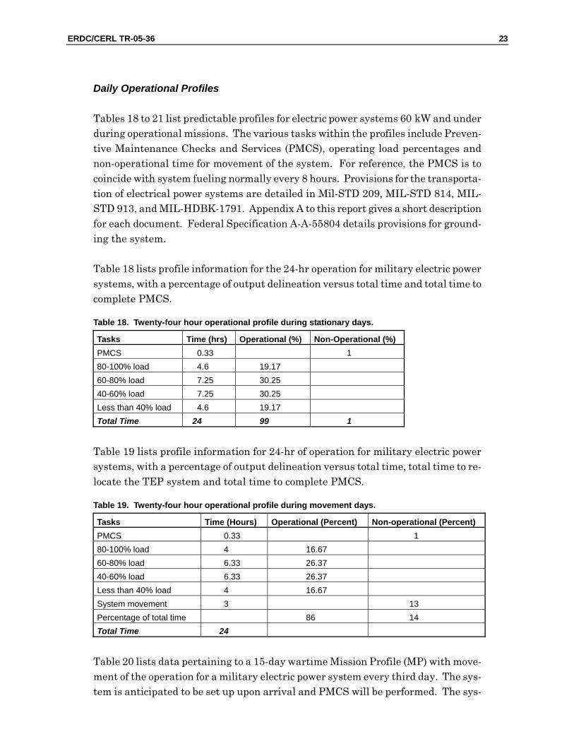
Daily Operational Profiles
Tables 18 to 21 list predictable profiles for electric power systems 60 kW and under during operational missions. The various tasks within the profiles include Preven-tive Maintenance Checks and Services (PMCS), operating load percentages and non-operational time for movement of the system. For reference, the PMCS is to coincide with system fueling normally every 8 hours. Provisions for the transporta-tion of electrical power systems are detailed in Mil-STD 209, MIL-STD 814, MIL-STD 913, and MIL-HDBK-1791. Appendix A to this report gives a short description for each document. Federal Specification A-A-55804 details provisions for ground-ing the system.
Table 18 lists profile information for the 24-hr operation for military electric power systems, with a percentage of output delineation versus total time and total time to complete PMCS.
Table 18. Twenty-four hour operational profile during stationary days.
Tasks Time (hrs) Operational (%) Non-Operational (%) PMCS 0.33 1 80-100% load 4.6 19.17 60-80% load 7.25 30.25 40-60% load 7.25 30.25 Less than 40% load 4.6 19.17 Total Time 24 99 1
Table 19 lists profile information for 24-hr of operation for military electric power systems, with a percentage of output delineation versus total time, total time to re-locate the TEP system and total time to complete PMCS.
Table 19. Twenty-four hour operational profile during movement days.
Tasks Time (Hours) Operational (Percent) Non-operational (Percent) PMCS 0.33 1 80-100% load 4 16.67 60-80% load 6.33 26.37 40-60% load 6.33 26.37 Less than 40% load 4 16.67 System movement 3 13 Percentage of total time 86 14 Total Time 24
Table 20 lists data pertaining to a 15-day wartime Mission Profile (MP) with move-ment of the operation for a military electric power system every third day. The sys-tem is anticipated to be set up upon arrival and PMCS will be performed. The sys-
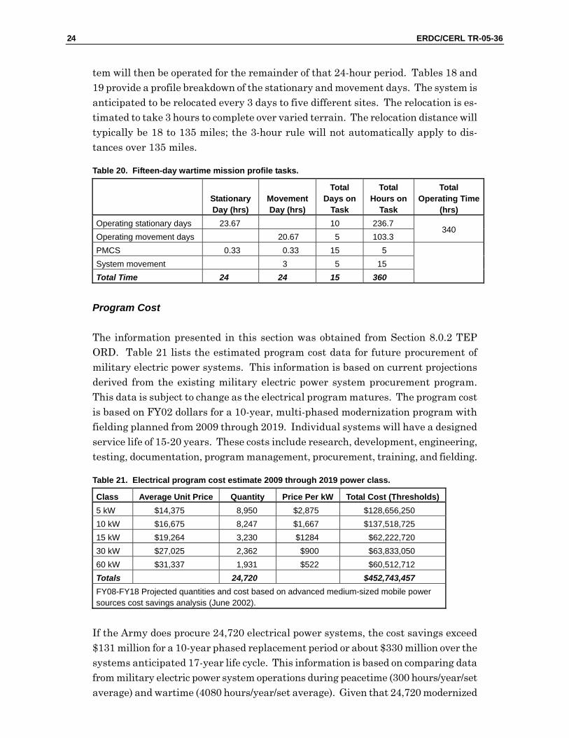
24 ERDC/CERL TR-05-36
tem will then be operated for the remainder of that 24-hour period. Tables 18 and 19 provide a profile breakdown of the stationary and movement days. The system is anticipated to be relocated every 3 days to five different sites. The relocation is es-timated to take 3 hours to complete over varied terrain. The relocation distance will typically be 18 to 135 miles; the 3-hour rule will not automatically apply to dis-tances over 135 miles.
Table 20. Fifteen-day wartime mission profile tasks.
StationaryDay (hrs)
MovementDay (hrs)
Total Days on
Task
Total Hours on
Task
Total Operating Time
(hrs) Operating stationary days 23.67 10 236.7 Operating movement days 20.67 5 103.3
340
PMCS 0.33 0.33 15 5 System movement 3 5 15 Total Time 24 24 15 360
Program Cost
The information presented in this section was obtained from Section 8.0.2 TEP ORD. Table 21 lists the estimated program cost data for future procurement of military electric power systems. This information is based on current projections derived from the existing military electric power system procurement program. This data is subject to change as the electrical program matures. The program cost is based on FY02 dollars for a 10-year, multi-phased modernization program with fielding planned from 2009 through 2019. Individual systems will have a designed service life of 15-20 years. These costs include research, development, engineering, testing, documentation, program management, procurement, training, and fielding.
Table 21. Electrical program cost estimate 2009 through 2019 power class.
Class Average Unit Price Quantity Price Per kW Total Cost (Thresholds) 5 kW $14,375 8,950 $2,875 $128,656,250 10 kW $16,675 8,247 $1,667 $137,518,725 15 kW $19,264 3,230 $1284 $62,222,720 30 kW $27,025 2,362 $900 $63,833,050 60 kW $31,337 1,931 $522 $60,512,712 Totals 24,720 $452,743,457 FY08-FY18 Projected quantities and cost based on advanced medium-sized mobile power sources cost savings analysis (June 2002).
If the Army does procure 24,720 electrical power systems, the cost savings exceed $131 million for a 10-year phased replacement period or about $330 million over the systems anticipated 17-year life cycle. This information is based on comparing data from military electric power system operations during peacetime (300 hours/year/set average) and wartime (4080 hours/year/set average). Given that 24,720 modernized
ERDC/CERL TR-05-36 25
generators are procured that are 15 percent more fuel-efficient and 20 percent more reliable, these improvements are anticipated to yield the savings mentioned. This is based on an initial $30M Research Development Test and Evaluation (RDTE) in-vestment; the return on investment (ROI) is about 4.5 years. These savings are combined with fielding modernized generators using advanced technology that will yield significant operational benefits (TEP ORD Resource Summary).
System Training Concept
The development and acquisition of future military electric power systems will re-quire additional training for the Power Generation Equipment Repairer known as Military Occupational Specialty 52 (MOS 52) and their supervisors. It is antici-pated that the existing Basic Noncommissioned Officer Course (BNCOC), Advanced Noncommissioned Officer Course (ANCOC), Warrant Officer Basic Course (WOBC), and Warrant Officer Advance Course (WOAC) will be enhanced to address future training requirements. The following guidelines for training on future electric power systems was obtained from the TEP ORD: • Maintenance training will not impact manpower requirements. • The Material Developer will provide a multimedia Training Support Package
(TSP). • Maintenance training will be provided by the Ordnance Mechanical Mainte-
nance School (OMMS). • Future electrical power systems will not require new MOSs and minimize
any increase in system operational complexity or maintenance. • The Material Developer will ensure that Test, Measurement and Diagnostic
Equipment (TMDE) or any special tools are on hand for system fielding and for New Equipment Training (NET).
The future training concept indicates that it is the responsibility of the Material Developer to develop a comprehensive multimedia TSP and products to support all aspects of training on the future electrical power systems. It will also be the re-sponsibility of the Material Developer to train instructors and key personnel.
The events and activities necessary for future training are defined in the Automatic System Approach to Training (ASAT) and are to be implemented in the develop-ment of the Training Plan. It will be the responsibility of the Material Developer to maintain and update the training materials throughout the life cycle of the system. The Material Developer will also monitor the institutional trainers and update the training program as needed.
26 ERDC/CERL TR-05-36
5 Design Considerations and Recommendations This chapter contains design considerations generated during the this study. Al-though these topics are not necessarily covered by the TEP ORD, they should how-ever be considered during the early stages of designing the SOFC system. High-level design recommendations generated during this effort are also presented.
Design Considerations
This section describes several areas that should be considered during the design phase of the SOFC system including the possible need for water to operate, sulfur content in logistical fuels, and fuel additives that enhance fuel performance.
Water Availability
Fuel Cell Technology Team Consultant Walter Taschek stated that “Supplying wa-ter in the field will have a logistic impact not so much because it takes water away from the soldier, but that it must be provided and that it must be clean.” SOFC power systems requiring water to operate could negatively impact the logistical footprint reduction objectives of the TEP program. Therefore, SOFC systems will be much more attractive it they were self-sustaining and did not require water. Even if there was water available in the Area of Operation (AOR), equipment may be re-quired to process the water so that it would be useable in the SOFC.
An existing Quadripartite Standardization Agreement (QSTAG) titled “QSTAG2028 ED.1 Bulk Water Supply on Extended Operations” is currently listed as the “Con-trolled Distribution Document.” (This document is not available to the general pub-lic.) The aim of this QSTAG is to agree on the minimum compatible doctrine for bulk water supply on extended operations.
Sulfur Content in Military Fuels
The Detail Specification of MIL-DTL-83133E covers three grades of kerosene type aviation turbine fuels consisting of NATO F-34 (JP-8), NATO F-35, and JP-8+100. The document states the maximum total sulfur content in percent mass is 0.30.
ERDC/CERL TR-05-36 27
The Commercial Item Description (CID) for fuel oil and diesel suitable for use in ground compression-ignition and gas turbine engines and other diesel fuel consum-ing equipment provides information on two grade designations:
1. Grade Low Sulfur No. 1-D, which is a special-purpose, light distillate fuel used for automotive diesel and gas turbine engines requiring low sulfur fuel and re-quiring a higher volatility than that provided by Grade Low Sulfur No. 2-D.
2. Grade Low Sulfur No. 2-D, which is a general-purpose middle distillate fuel used for automotive diesel and gas turbine engines requiring low sulfur fuel. It is also suitable for use in non-automotive application. The Grade Low Sulfur has a sul-fur level no higher than 0.05 percent by weight.
Under authority of the Clean Air Act, the USEPA issues limits on the maximum sulfur level, the maximum aromatic content or minimum cetane index on diesel in-tended for on-road use. According to the Clean Air Act, the sulfur content require-ments for diesel fuel, effective 1 October1993, shall not exceed 0.05 percent concen-tration (by weight) or fail to meet a minimum cetane index of 40.
A caution on this subject of fuel sulfur content is that in a time of war, a commander will use the fuel that is available to him. Therefore, the fact remains that the sulfur content could be outside the above stated limits. The sulfur content of middle distil-lates depends on the source of crude oil. The sulfur content of some diesel fuels ranges from 0.01 to greater that 3 percent. It is not recommended that the SOFC system be designed to handle the worst scenarios, however it is recommended that options for future developments provide a reliable path forward.
Diesel Fuel and NATO F-34 (JP-8) Additives
Aviation fuel additives are fuel soluble chemicals added in small amounts to im-prove or maintain properties important to fuel performance or fuel handling. Typi-cally, additives are derived from petroleum-based raw materials, and their function and chemistry are highly specialized. They produce the desired results in the parts per million-concentration range. One ppm is 0.0001 mass percent.
Military Detail Specification MIL-DTL-83133E defines F-34 (JP-8) as a kerosene type turbine fuel that contains a static dissipating additive, corrosion inhibi-tor/lubricity improver, and fuel system icing inhibitor and may contain antioxidant and metal deactivator.
28 ERDC/CERL TR-05-36
Static Dissipater for JP-8
Jet fuel has poor electrical conductivity and can present potential safety hazards under certain conditions. Additives have been developed that improve the fuel con-ductivity and are referred to as static dissipaters.
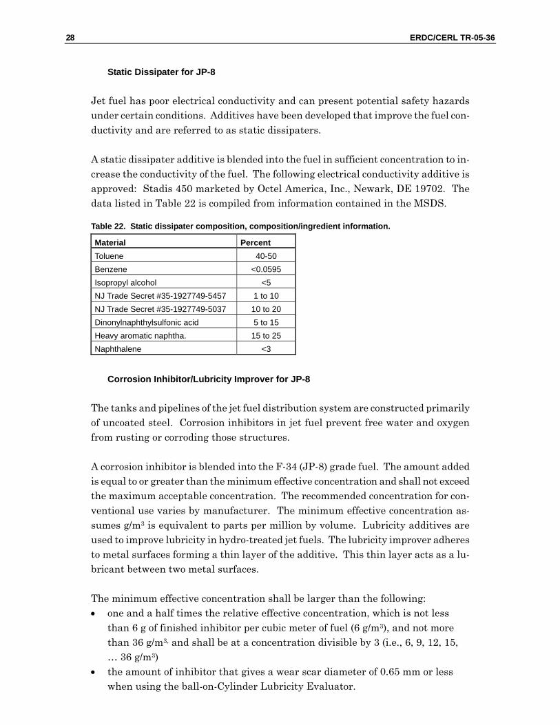
A static dissipater additive is blended into the fuel in sufficient concentration to in-crease the conductivity of the fuel. The following electrical conductivity additive is approved: Stadis 450 marketed by Octel America, Inc., Newark, DE 19702. The data listed in Table 22 is compiled from information contained in the MSDS.
Table 22. Static dissipater composition, composition/ingredient information.
Material Percent Toluene 40-50 Benzene <0.0595 Isopropyl alcohol <5 NJ Trade Secret #35-1927749-5457 1 to 10 NJ Trade Secret #35-1927749-5037 10 to 20 Dinonylnaphthylsulfonic acid 5 to 15 Heavy aromatic naphtha. 15 to 25 Naphthalene <3
Corrosion Inhibitor/Lubricity Improver for JP-8
The tanks and pipelines of the jet fuel distribution system are constructed primarily of uncoated steel. Corrosion inhibitors in jet fuel prevent free water and oxygen from rusting or corroding those structures.
A corrosion inhibitor is blended into the F-34 (JP-8) grade fuel. The amount added is equal to or greater than the minimum effective concentration and shall not exceed the maximum acceptable concentration. The recommended concentration for con-ventional use varies by manufacturer. The minimum effective concentration as-sumes g/m3 is equivalent to parts per million by volume. Lubricity additives are used to improve lubricity in hydro-treated jet fuels. The lubricity improver adheres to metal surfaces forming a thin layer of the additive. This thin layer acts as a lu-bricant between two metal surfaces.
The minimum effective concentration shall be larger than the following: • one and a half times the relative effective concentration, which is not less
than 6 g of finished inhibitor per cubic meter of fuel (6 g/m3), and not more than 36 g/m3, and shall be at a concentration divisible by 3 (i.e., 6, 9, 12, 15, … 36 g/m3)
• the amount of inhibitor that gives a wear scar diameter of 0.65 mm or less when using the ball-on-Cylinder Lubricity Evaluator.
ERDC/CERL TR-05-36 29
The maximum allowable concentration shall be the lowest of the following: • 54 g/m3 • four times the relative effective concentration, which is not less than 6 g of
finished inhibitor per cubic meter of fuel (6 g/m3) and not more than 36 g/m3, and shall be at a concentration divisible by 3 (i.e., 6, 9, 12, 15, … 36 g/m3)
• the highest concentration that results in Micro-Separometer rating of 70 or higher
• the highest concentration that results in a less than 40 percent change in electrical conductivity with fuel containing a static dissipater.
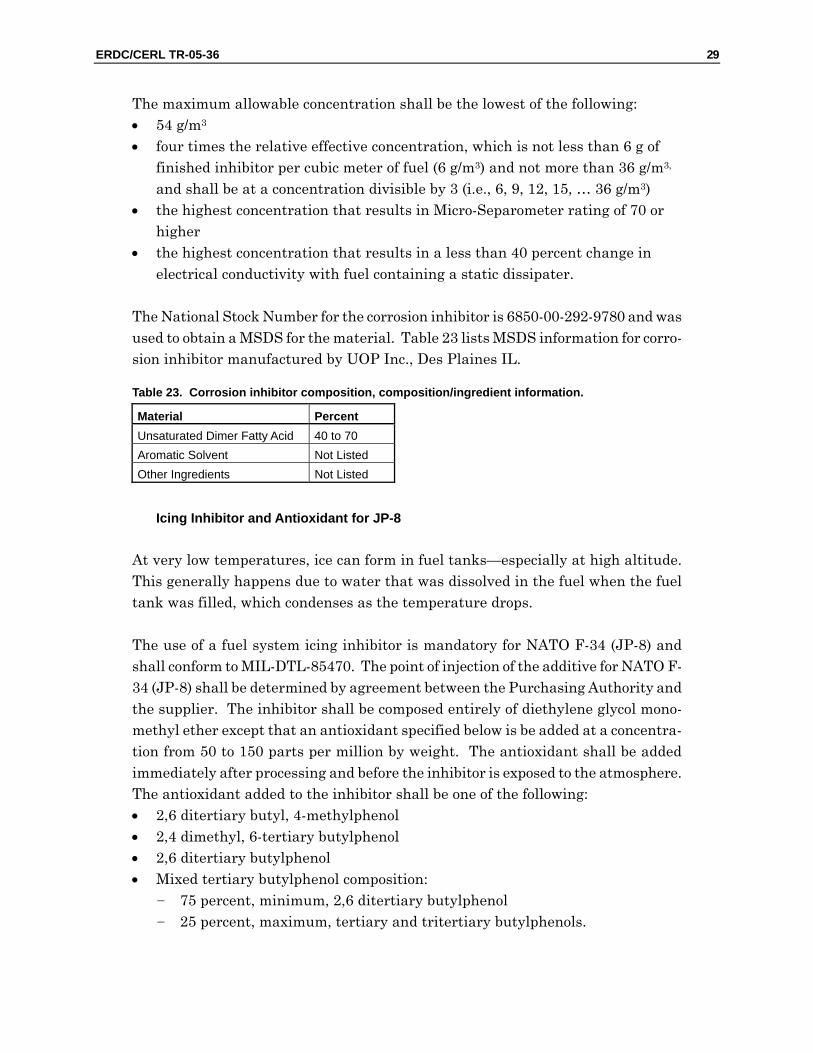
The National Stock Number for the corrosion inhibitor is 6850-00-292-9780 and was used to obtain a MSDS for the material. Table 23 lists MSDS information for corro-sion inhibitor manufactured by UOP Inc., Des Plaines IL.
Table 23. Corrosion inhibitor composition, composition/ingredient information.
Material Percent Unsaturated Dimer Fatty Acid 40 to 70 Aromatic Solvent Not Listed Other Ingredients Not Listed
Icing Inhibitor and Antioxidant for JP-8
At very low temperatures, ice can form in fuel tanks—especially at high altitude. This generally happens due to water that was dissolved in the fuel when the fuel tank was filled, which condenses as the temperature drops.
The use of a fuel system icing inhibitor is mandatory for NATO F-34 (JP-8) and shall conform to MIL-DTL-85470. The point of injection of the additive for NATO F-34 (JP-8) shall be determined by agreement between the Purchasing Authority and the supplier. The inhibitor shall be composed entirely of diethylene glycol mono-methyl ether except that an antioxidant specified below is be added at a concentra-tion from 50 to 150 parts per million by weight. The antioxidant shall be added immediately after processing and before the inhibitor is exposed to the atmosphere. The antioxidant added to the inhibitor shall be one of the following: • 2,6 ditertiary butyl, 4-methylphenol • 2,4 dimethyl, 6-tertiary butylphenol • 2,6 ditertiary butylphenol • Mixed tertiary butylphenol composition:
- 75 percent, minimum, 2,6 ditertiary butylphenol - 25 percent, maximum, tertiary and tritertiary butylphenols.
30 ERDC/CERL TR-05-36
Metal Deactivator for JP-8
Metal deactivators form stable complexes with metal ions that are effective cata-lysts for oxidation reactions like copper and zinc. These metals are not typically used in fuel systems, however, if the fuel becomes contaminated, metal deactivators inhibit their catalytic activity.
A metal deactivator may be blended into the fuel. The concentration of active mate-rial used on the initial batching of the fuel shall not exceed a concentration of 5.7 mg/L. Metal deactivator shall not be used in JP-8 unless the supplier is given writ-ten by the procuring agency or user.
According to Military Detail Specification MIL-DTL-83133E, the metal deactivator added to JP-8 is N,N'–disalicylidene-1,2-propanediamine.
CI Solvent Red 164 for Diesel Fuel
A confusing situation for both refiners and purchasers of diesel fuel has arisen be-cause both the Internal Revenue Service (IRS) and the USEPA require the addition of red dye to certain classes of diesel fuel. However, each agency requires that the dye be added to a different class of fuel, at a different concentration, and for a dif-ferent reason. The USEPA wants to identify diesel fuel with high sulfur content to ensure that it is not used in on-road vehicles. The IRS wants to ensure that tax-exempt low sulfur and high sulfur diesel fuel are not used for taxable purposes. The IRS regulations require that tax-exempt diesel fuels, both high sulfur and low sul-fur, have a minimum level of a Solvent Red 164 dye that is spectrally equivalent 3.9 lb of the solid dye standard Solvent Red 26 per thousand barrels (bbl) or 11.1 mg/L of diesel fuel. This level of dye is more than five times the amount required by the USEPA regulations. The IRS contends that the high dye level is necessary to allow detection of tax evasion even after five-fold dilution of dyed fuel with un-dyed fuel.
According to the MSDS the ingredients are (no volume or percentage listed): • 2-Napthalenol [(Phenylazo) phenyl]-Azo Alkyl Derivatives • Benzene • Ethyl Benzene • Other absorbent materials.
Ground Fuel Additive to Optimize Lubricity
Paradyne 655 additive is manufactured by Exxon and used as a lubricity improver in ground fuels. It is used where severe wear problems exist and when fuel has been tested and found to have very low lubricity. The recommended concentration
ERDC/CERL TR-05-36 31
is 80 ppm by volume, but can be increased to 200 ppm if needed. Paradyne 655 could not be found in any known MSDS resources or on the Exxon web site.
Ground Turbine or Diesel Stabilizer/Biocide
The diesel fuel stabilizer additive is used to prevent or slow the formation of dete-rioration products in ground fuels due to auto-oxidation and to eliminate microbi-ological growth. The system includes an antioxidant, metal deactivator, corrosion inhibitor, detergent dispersant and biocide. It is available in one and two package systems. The recommended concentration for the additives varies by manufacturer.
Design Recommendations
Most of the recommendations generated during this effort are “rule of thumb” items to consider during the initial design stages. (Some will require a detailed analysis.) One important thing to keep in mind is to allow for an iterative design approach that will allow technological improvements to be incorporated into the system throughout its life cycle.
Minimum Stack Voltage
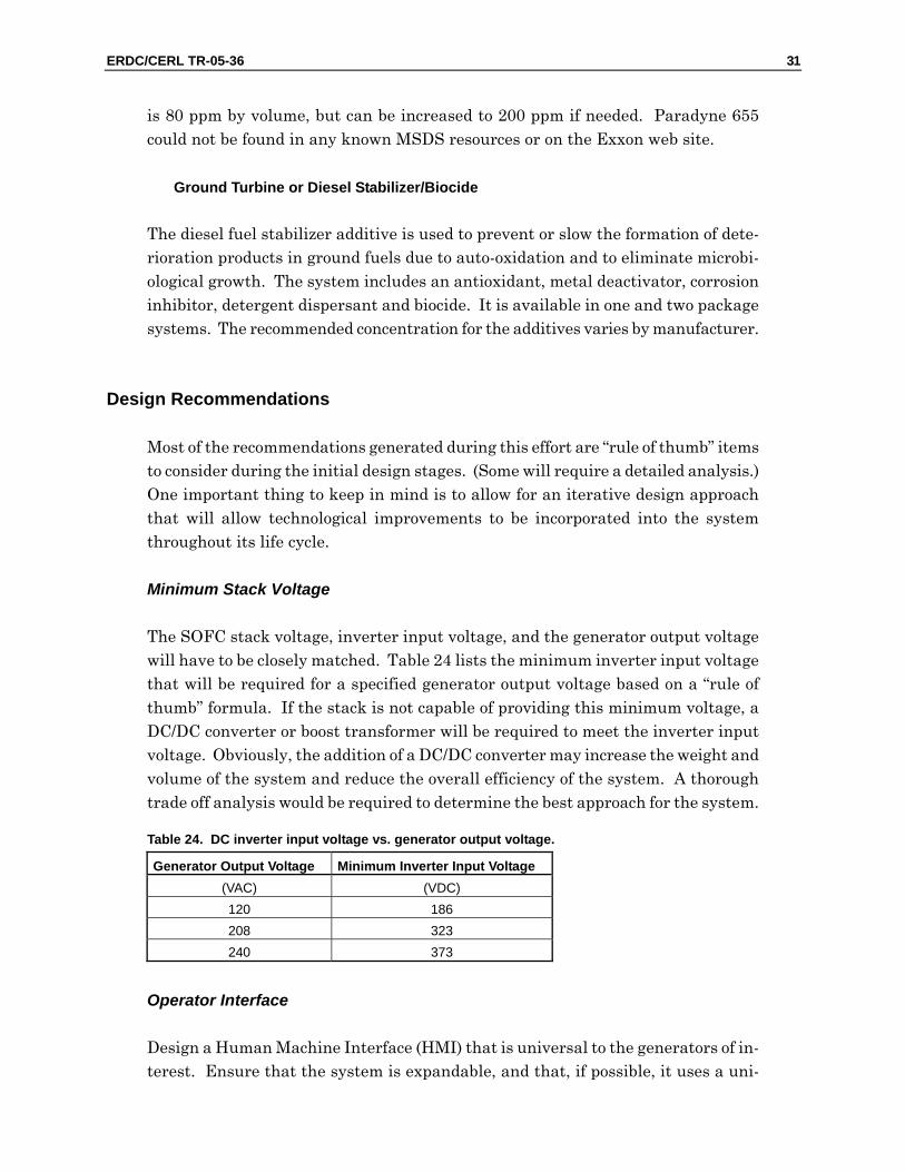
The SOFC stack voltage, inverter input voltage, and the generator output voltage will have to be closely matched. Table 24 lists the minimum inverter input voltage that will be required for a specified generator output voltage based on a “rule of thumb” formula. If the stack is not capable of providing this minimum voltage, a DC/DC converter or boost transformer will be required to meet the inverter input voltage. Obviously, the addition of a DC/DC converter may increase the weight and volume of the system and reduce the overall efficiency of the system. A thorough trade off analysis would be required to determine the best approach for the system.
Table 24. DC inverter input voltage vs. generator output voltage.
Generator Output Voltage Minimum Inverter Input Voltage (VAC) (VDC) 120 186 208 323 240 373
Operator Interface
Design a Human Machine Interface (HMI) that is universal to the generators of in-terest. Ensure that the system is expandable, and that, if possible, it uses a uni-
32 ERDC/CERL TR-05-36
form control scheme, including layout and operation of switches, buttons, and sys-tem readouts.
Preventive Maintenance Checks and Services
The system should be designed for manufacturing, troubleshooting, and repair. Ac-cess to internal components should be easily accessible with removable side panels and top covers. Filters, fluid drains, and fluid fill caps should be easily accessible for PMCS.
Control System
When possible, design all control systems to use the same control methodology and electronic control components. Use the same sensors to monitor and control the sys-tem and provide safety. Scaling factors could be changed to meet the need of differ-ent power levels.
Improved Efficiency
Evaluate possible methods to improve overall system efficiency. There may be a break point at a certain power lever where it may make sense to incorporate co-generation to take advantage of waste heat. This may also provide benefit in reduc-ing the thermal signature of the system. A systems approach is recommended to investigate optimum operating ranges for all major subcomponents working in the system.
ERDC/CERL TR-05-36 33
6 Modularization This chapter discusses current mobile electrical power capabilities, provides high-level considerations for a modularization plan, and identifies several potential bene-fits of a modularization plan.
Capabilities Assessment
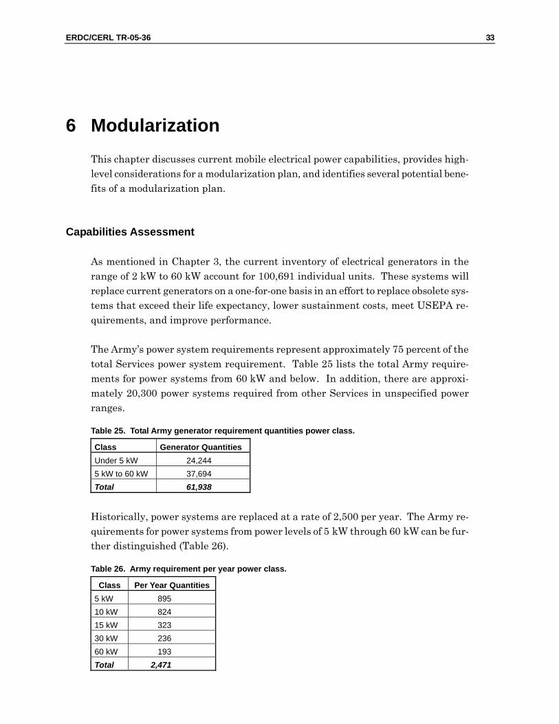
As mentioned in Chapter 3, the current inventory of electrical generators in the range of 2 kW to 60 kW account for 100,691 individual units. These systems will replace current generators on a one-for-one basis in an effort to replace obsolete sys-tems that exceed their life expectancy, lower sustainment costs, meet USEPA re-quirements, and improve performance.
The Army’s power system requirements represent approximately 75 percent of the total Services power system requirement. Table 25 lists the total Army require-ments for power systems from 60 kW and below. In addition, there are approxi-mately 20,300 power systems required from other Services in unspecified power ranges.
Table 25. Total Army generator requirement quantities power class.
Class Generator Quantities Under 5 kW 24,244 5 kW to 60 kW 37,694 Total 61,938
Historically, power systems are replaced at a rate of 2,500 per year. The Army re-quirements for power systems from power levels of 5 kW through 60 kW can be fur-ther distinguished (Table 26).
Table 26. Army requirement per year power class.
Class Per Year Quantities 5 kW 895 10 kW 824 15 kW 323 30 kW 236 60 kW 193 Total 2,471
34 ERDC/CERL TR-05-36
As the data in Table 26 suggest, the generators in the 5 and 10 kW power classes account for nearly 70 percent of the total Army per year requirements.
Modularization Approach
Many different aspects must be considered to develop a Modularization Plan. Sys-tem cost, weight, volume, and efficiency are just a few topics that should be consid-ered. Another important factor in the determination of a modularization approach is the technology used in the power system. The entry of SOFC technology in the early stages of its infancy is an ideal opportunity to take a “System of Systems” ap-proach to develop and analyze the modularization plan. The development of a Modularization Plan and the complete analysis that is required to support the plan is beyond the scope of this task. However, the intent of this work is to provide dis-cussions and considerations that will spawn a design approach that could benefit from a modularization plan. One of the assumptions that will be used is that the existing generator power classes will remain the same (i.e., 2, 3, 5, 10, 15, 30, & 60 kW). This is important to mention and to follow in the future based on conversa-tions with Mr. Walter Taschek, Fuel Cell Technology Team Consultant at the PM MEP, who expressed the opinion that the current 5 kW and smaller generators should be matched for size, and that the military would benefit if there would be more generator size options in the 10 kW and larger size range.
Modularization Considerations
Based on the requirements for electrical power systems listed in Chapter 4, a major-ity of the units are in the power range from 10 kW and below. With limited knowl-edge of the exact power level listed in the “Under 5 kW” category, it is impossible to generate a plan without some speculation. Based on the existing systems, one can assume the military will continue to require 2 kW and 3 kW systems. However, there is hint in the TEP ORD that the range “Under 5 kW range” will include 0.5 kW through 3 kW.
Assume for a moment that the smallest power level required by the military was 2.5 kW and it is feasible to build a module at this power level, this could prove to be an ideal base module. Two modules could be combined for a 5 kW power system and four modules could be combined for a 10 kW power system.
Unfortunately, it is not that easy. Power density, weight, efficiency, all cost consid-erations, inverter requirements, system reliability, and DOD requirements will all need to be analyzed and given the appropriate consideration. The military is con-
ERDC/CERL TR-05-36 35
tinually looking for electric power solutions that will reduce operations and sus-tainment costs, fuel usage, weight, acoustic signature and that will increase reliabil-ity and ease maintainability. Additionally, SOFCs are no different than any other technology in regards to the need to identify the niche market. Therefore, what makes sense from the technology must also be thoroughly considered.
One approach that could be taken for future activities is to develop a modularization plan based on technology (i.e., fuel cell, system components, and inverters) and as-sume that the DOD generator sizes will remain consistent with today’s require-ments. Nevertheless, it is recommended that any future development be coordi-nated with PM-MEP to remain on top the DOD’s needs and requirements.
Based on the analysis, it may be determined that a 1 kW module size is the best choice based on power density, weight, efficiency, cost, and reliability. If this were the case, the 2, 3, 5, and 10 kW systems could be made up of 1 kW modules stacked together in a chassis. Standard chassis sizes for three and five modules could be used for all systems from 2 through 10 kW power systems. In this scenario, the 2 kW systems would have an empty slot and the 10 kW system would be made up of two, five-slot chassis.
To reap the benefits of a modulation plan, one must also consider the potential benefits in the design process. One should take advantage of mass production and the use of identical components to reduce training, maintenance, and logistics. One approach is to develop a decision matrix that lists all pertinent criteria by which al-ternatives will be assessed. Each alternative will be assessed against the stated cri-teria and assign a numeric value for each alternative’s ability to meet the criteria. Stakeholders would be solicited to assign a weighting factor to each criterion to de-termine the level of importance. The solution with the highest score is the “winner.”
Modularization Benefits
Several potential benefits could be realized from a modular approach to mobile elec-tric power. The potential benefits could include reduce logistics, reduce system cost, and reduced training and maintenance. The identification of a common sized SOFC module could decrease the overall cost of fabrication through: • bulk purchases of balance of plant components such as catalytic material,
system pumps, sensors, readouts, solenoids, tubing, etc. • mass production of the SOFC stack component, electronic control system,
wiring harnesses, chassis, and reformer sections.
36 ERDC/CERL TR-05-36
Reduction of Training and Maintenance Requirements
One benefit of adopting a modular approach to SOFC systems is the potential for reducing training and maintenance requirements. Reducing the medium generator fleet to a lesser quantity of SOFC module sizes means that technicians would re-quire less classroom training and the users would need to keep fewer maintenance and replacement on hand. The standardization of the SOFC modules’ control sys-tem will decrease the time needed to train and familiarize personnel with the equipment. The addition of controls to identify problems and indicate needed main-tenance will help maintenance workers to reduce downtime and will alert operators to potential problems. Some of the training and maintenance benefits are : • Training benefits:
- Reducing the seven variations of medium power generating options would allow personnel to be trained more efficiently throughout the SOFC mod-ule range. Adopting a modular approach would allow personnel trained on the 1 kW module to be capable of working on 1 kW through 3 kW sys-tems. The same would hold true for the 5 kW and 25 kW modules.
- Using one control system while factoring in the necessary control differ-ences for the different SOFC module sizes would promote the commonal-ity of the SOFC systems and reduce the number of control systems per-sonnel would need to be trained to operate, maintain and repair.
- Developing inverters capable of producing the required voltage and fre-quency output would reduce the overall time needed to complete training across the generating fleet.
- Standardizing the modular layout for the SOFC module sizes will de-crease the time needed to train personnel on subsequent systems.
• Maintenance benefits: - Use of one control system that can be loaded with system specific parame-
ters and set points will reduce maintenance inventory and increase the maintenance performers expertise.
- Use of the same control sensors for all SOFC modules will reduce the maintenance inventory.
- Use of the same controlled devices, where appropriate, will reduce the maintenance inventory.
- Incorporating sensors into the control system will help identify problems needed maintenance, thereby reducing down time.
- SOFC modules with removable side panels and top covers will permit straightforward PMCS and component replacement.
ERDC/CERL TR-05-36 37
7 Conclusions This work has identified Federal and Military Specifications, Standards, and Hand-books pertinent to the fielding of SOFCs into U.S. Services as a source of military power systems, and other documents that are pertinent to the development of SOFC military power systems (<60 kW) based on information gathered through as-sessments of current applications and procurement requirements for military elec-tric power. Other information relevant to SOFC military power systems develop-ment was gathered from discussions with user groups and procurement agencies, research via various DOD Web sites, and two off-site meetings held with leadership level personnel at WR-ALC and PM-MEP at Fort Belvoir.
This work has shown that the current inventory of MEP within the 2 kW to 60 kW range, accounts for 100,691 individual units with a combined generating capacity of 1,037,725 kW. The total inventory will be expanded by 25,848 individual units by the end of 1QFY07. Although the TQG family does meet current military needs and production will continue through 2008, it will not comply with pending USEPA regulations. Furthermore, engine manufacturers will cease production of non-compliant replacement engines for the current generators, which will eventually render the current MEP fleet obsolete.
The goal of the PM-MEP is to field systems to replace the obsolete systems exceed-ing their life expectancy by 5 years, lower sustainment costs, meet USEPA require-ments and improve performance. It is estimated that the Army will procure an ini-tial quantity of 24,720 medium output systems over a 10-year period. During this time, existing generators will be replaced with future electric power systems, which will be characterized by:
1. Reduced weight and footprint requirements enhancing deployment throughout the generator spectrum.
2. Increased fuel efficiency, which will reduce fuel tanker fleet size and further de-crease the logistical footprint
3. Ability to meet stringent “Mean Time Between Failure” probability goals to oper-ate without an essential function failure
4. Ability to meet median and maximum repair times for unscheduled maintenance to ensure reliability and not adversely affect mission critical C4ISR systems.
This study has compiled predictable daily operating profiles for future electric power systems 60 kW and below during operational missions, including PMCS, op-
38 ERDC/CERL TR-05-36
erating load percentages, and non-operational time for movement of the system, in-cluding a 15-day wartime Mission Profile with movement of the mobile electric power system every third day (Chapter 4).
This study has explored current SOFC capabilities, described high-level considera-tions for a modularization plan, and identified potential benefits of adopting a sim-plified, modular approach to SOFC systems, which is anticipated to reduce training, streamline maintenance requirements, reduce logistics, and minimize procurement cost and simplify.
A future tasking, beyond the scope of this effort, could generate a matrix based the modularization approach described in Chapter 6, by obtaining priorities from all stakeholders, and performing a detailed analysis to develop a modularization plan that takes advantage of the solid oxide fuel cell technology and provides the most benefit to DOD.
ERDC/CERL TR-05-36 39
References
Department of Defense (DOD), Military Standard 810E, Environmental Test Methods and Engineering Guidelines (DOD, released 14 July 1989).
DOD Program Manager, Mobile Electric Power, Proposed Department of Defense Handbook, MIL-HDBK-633F, Standard Family of Mobile Electric Power Generating Sources, General Description Information and Characteristics Data Sheets, prepared by Modern Technologies Corporation (MTC) (2004).
Directorate of Combat Developments for Ordnance, ATCL-O, U.S. Army Combined Arms Support Command, Tactical Electric Power Operational Requirements Document (ORD) 0.5 kW to 200 kW Tactical Electric Power (TEP) ACAT LEVEL: 3, prepared by Timothy Raney, MTC (7 July 2003).
Senate FY03 Defense Appropriations Bill (SRpt. 107-213), Solid Oxide Fuel Cell Development, line 52, “Military Engineering Advanced Technology.”
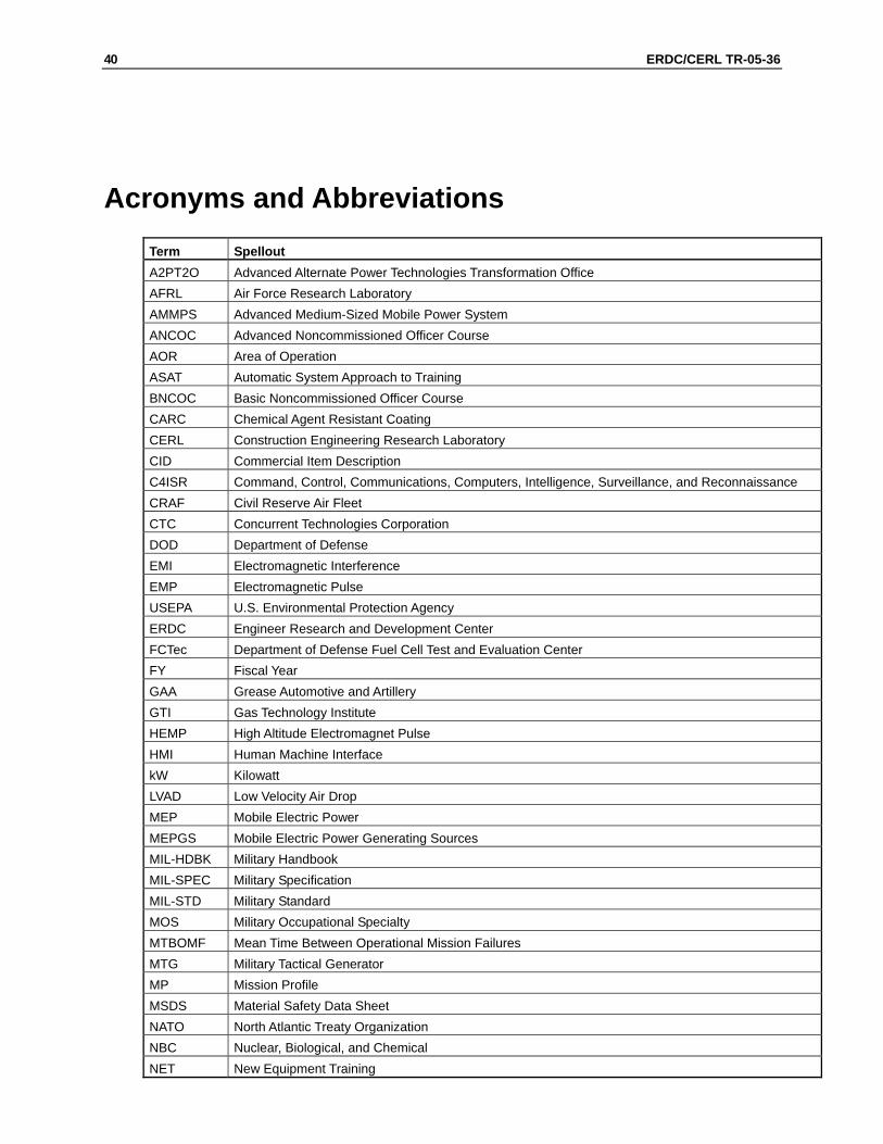
40 ERDC/CERL TR-05-36
Acronyms and Abbreviations Term Spellout A2PT2O Advanced Alternate Power Technologies Transformation Office AFRL Air Force Research Laboratory AMMPS Advanced Medium-Sized Mobile Power System ANCOC Advanced Noncommissioned Officer Course AOR Area of Operation ASAT Automatic System Approach to Training BNCOC Basic Noncommissioned Officer Course CARC Chemical Agent Resistant Coating CERL Construction Engineering Research Laboratory CID Commercial Item Description C4ISR Command, Control, Communications, Computers, Intelligence, Surveillance, and Reconnaissance CRAF Civil Reserve Air Fleet CTC Concurrent Technologies Corporation DOD Department of Defense EMI Electromagnetic Interference EMP Electromagnetic Pulse USEPA U.S. Environmental Protection Agency ERDC Engineer Research and Development Center FCTec Department of Defense Fuel Cell Test and Evaluation Center FY Fiscal Year GAA Grease Automotive and Artillery GTI Gas Technology Institute HEMP High Altitude Electromagnet Pulse HMI Human Machine Interface kW Kilowatt LVAD Low Velocity Air Drop MEP Mobile Electric Power MEPGS Mobile Electric Power Generating Sources MIL-HDBK Military Handbook MIL-SPEC Military Specification MIL-STD Military Standard MOS Military Occupational Specialty MTBOMF Mean Time Between Operational Mission Failures MTG Military Tactical Generator MP Mission Profile MSDS Material Safety Data Sheet NATO North Atlantic Treaty Organization NBC Nuclear, Biological, and Chemical NET New Equipment Training
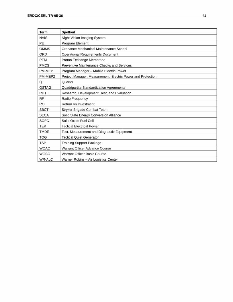
ERDC/CERL TR-05-36 41
Term Spellout NVIS Night Vision Imaging System PE Program Element OMMS Ordnance Mechanical Maintenance School ORD Operational Requirements Document PEM Proton Exchange Membrane PMCS Preventive Maintenance Checks and Services PM-MEP Program Manager – Mobile Electric Power PM-MEP2 Project Manager, Measurement, Electric Power and Protection Q Quarter QSTAG Quadripartite Standardization Agreements RDTE Research, Development, Test, and Evaluation RF Radio Frequency ROI Return on Investment SBCT Stryker Brigade Combat Team SECA Solid State Energy Conversion Alliance SOFC Solid Oxide Fuel Cell TEP Tactical Electrical Power TMDE Test, Measurement and Diagnostic Equipment TQG Tactical Quiet Generator TSP Training Support Package WOAC Warrant Officer Advance Course WOBC Warrant Officer Basic Course WR-ALC Warner Robins – Air Logistics Center
42 ERDC/CERL TR-05-36
Appendix A: Federal and Military Specifications
1. Federal Specification A-A-52557 – Fuel Oil, Diesel; for Posts, Camps, and Sta-tions This Commercial Item Description (CID) covers requirements for two grades of low-sulfur diesel fuel oils suitable for use in ground compression-ignition and gas turbine engines as well as other diesel fuel consuming equipment. This diesel fuel is identified as NATO Code Number F-54. This CID does not cover diesel fu-els intended for use in areas where ambient temperatures lower than –32 °C generally occur.
2. Federal Specification A-A-52624 – Antifreeze, Multi Engine Type This CID covers the requirements for ethylene glycol-based and propylene glycol-based automotive engine antifreeze. The antifreeze is to be suitable for use in all administrative vehicles, construction, and material handling vehicles and equip-ment, and military ground combat and tactical vehicles and equipment.
3. Federal Specification A-A-55804 – Rod, Ground (with Attachments) This CID establishes the Government acquisition requirements for grounding electrodes with connecting cables and provisions for securing attachments to ex-posed noncurrent-carrying conductive materials of electrical equipment in mobile shops and temporary or permanent power stations, and to establish grounds in areas devoid of underground metallic water piping systems.
4. Federal Specification A-A-59616 – Pipe Fittings: Bushings, Locknuts, and Plugs; Iron, Steel, and Aluminum; (Threaded); 125-150 lb This CID covers the general requirements for iron, steel, or aluminum bushings, locknuts, and plugs that are used with threaded piping at working pressures be-tween 125 and 150 lb.
5. Military Specification MIL-PRF-2104 – Lubricating Oil, Internal Combustion Engine, Combat/Tactical Service (Not applicable to SOFC) This performance specification covers engine oils suitable for the lubrication of reciprocating internal combustion engines of both spark-ignition and compres-sion-ignition types and for power transmission fluid applications in com-bat/tactical service equipment.
6. Military Specification MIL-PRF-2105 – Lubricating Oil, Gear, Multipurpose (Metric) (Not applicable to SOFC) This performance specification covers multi-purpose gear-lubricating oils.
ERDC/CERL TR-05-36 43
7. Military Specification MIL-DTL-5624 – Turbine Fuel, Aviation, Grades JP-4, JP-5, and JP-5/JP-8 ST
8. Military Specification MIL-PRF-10924 – Grease, Automotive, and Artillery This specification covers one grade of a multi-purpose grease for the lubrication of ground vehicles, and equipment. It is identified by Military Symbol GAA and NATO Code Number G-403.
9. Military Specification MIL-PRF-21260 – Lubricating Oil, Internal Combustion Engine, Preservative Break-In (Not applicable to SOFC) This performance specification covers engine oils suitable for the preservation, break-in, and lubrication of reciprocating internal combustion engines of both spark-ignition and compression-ignition types. This Specification also covers power transmission fluid applications in equipment used in combat/tactical ser-vice.
10. Military Specification MIL-S-22473 – Sealing, Locking, and Retaining Com-pounds: (Single Compound) MIL-S-22473E, dated 12 April 1983, is hereby canceled. Future acquisitions for this item may refer to ASTM D5363, “Anaerobic Single-Component Adhesives.”
11. Military Specification MIL-PRF-46167 – Lubricating Oil, Internal Combustion Engine, Arctic (Not applicable to SOFC This performance specification covers one grade of internal combustion engine lubricating oil with military symbol OEA-30 and NATO Code O-184, suitable for arctic use.
12. Military Specification MIL-A-53009 – Additive, Antifreeze Extender, Liquid Cool-ing Systems This specification covers one type and one grade of additive intended for inhibit-ing water or reinhibiting used MIL-A-46153 antifreeze.
13. Military Specification MIL-C-53072 – Chemical Agent Resistant Coating (CARC) System Application Procedures and Quality Control Inspection This document covers the general requirements for application and inspection of the chemical agent resistant coating (CARC) system used on tactical military equipment. It is intended for use as a guide in selection of the appropriate mate-rials and procedures.
14. Military Specification MIL-DTL-64159 – Coating, Water Dispersible Aliphatic Polyurethane, Chemical Agent Resistant This specification covers water-dispersible, chemical agent resistant, aliphatic polyurethane coatings for use as a finish coat on all military tactical equipment including ground, aviation, and related support assets.
15. Military Specification MIL-DTL-83133 – Turbine Fuels, Aviation, Kerosene Types, NATO F-34 (JP-8), NATO F-35, and JP-8 + 100 This specification covers three grades of kerosene type aviation turbine fuel, NATO F-34 (JP-8), NATO F-35, and JP-8+100. This specification was thoroughly reviewed as a part of acquisition reform. While most of the requirements were
44 ERDC/CERL TR-05-36
converted to performance terms, due to the military-unique nature of the product and the need for compatibility with deployed systems, it was determined that not all requirements could be converted. The issuance of this specification as "detail" is not intended to constrain technology advances in future systems.
16. Military Specification MIL-L-85762 – Lighting, Aircraft, Interior, Night Vision Imaging System (NVIS) Compatible This specification covers two grades of aviation turbine fuel NATO F-40 (JP-4) and NATO F-44 (JP-5). This specification establishes performance, general con-figuration, and test and acceptance requirements for NVIS compatible aircraft interior lighting. It is applicable to all systems, subsystems, component equip-ment, and hardware providing the lighting environment in aircraft crew stations and compartments where NVIS are employed.
ERDC/CERL TR-05-36 45
Appendix B: Federal and Military Standards
1. Federal Standard FED-STD-595 – Colors Used in Government Procurement This standard presents the colors used by Government activities in a format suitable for color selection, color matching and for quality control inspection. This document describes the designation and use of the color chips of this stan-dard.
2. Military Standard MIL-STD-130 – Identification Marking of U.S. Military Prop-erty This standard provides the item marking criteria for development of specific marking requirements and methods for identification of items of military prop-erty produced, stocked, stored, and issued by or for the Department of Defense. This standard addresses criteria and data content for both human-readable in-formation and machine-readable information applications of item identification marking.
3. Military Standard MIL-STD-209 – Lifting and Tie Down Provisions This standard covers the design and testing of slinging, tie-down, and cargo tie-down provisions. The requirements in this standard are military-unique inter-face requirements developed specifically for ensuring that the lifting and tie-down provisions on military equipment meet the physical, functional and opera-tional environment attributes for transportation assets of the Defense Transpor-tation System.
4. Military Standard MIL-STD-461 – Requirements for the Control of Electromag-netic Interference Characteristics of Subsystems and Equipment This standard establishes interface and associated verification requirements for the control of the electromagnetic interference (emission and susceptibility) char-acteristics of electronic, electrical, and electromechanical equipment and subsys-tems designed or procured for use by activities and agencies of the Department of Defense. Such equipment and subsystems may be used independently or as an integral part of other subsystems or systems. This standard is best suited for items that have the following features: electronic enclosures that are no larger than an equipment rack, electrical interconnections that are discrete wiring har-nesses between enclosures, and electrical power input derived from prime power sources. This standard should not be directly applied to items such as modules located inside electronic enclosures or entire platforms. The principles in this
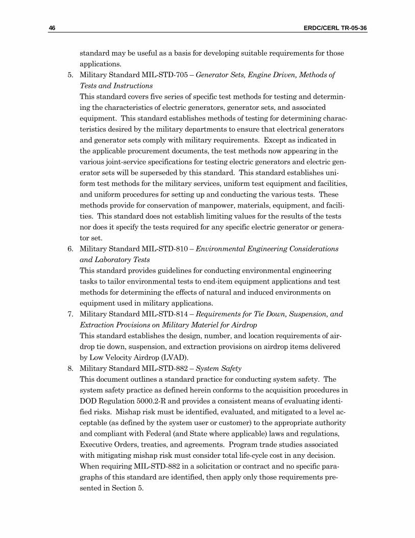
46 ERDC/CERL TR-05-36
standard may be useful as a basis for developing suitable requirements for those applications.
5. Military Standard MIL-STD-705 – Generator Sets, Engine Driven, Methods of Tests and Instructions This standard covers five series of specific test methods for testing and determin-ing the characteristics of electric generators, generator sets, and associated equipment. This standard establishes methods of testing for determining charac-teristics desired by the military departments to ensure that electrical generators and generator sets comply with military requirements. Except as indicated in the applicable procurement documents, the test methods now appearing in the various joint-service specifications for testing electric generators and electric gen-erator sets will be superseded by this standard. This standard establishes uni-form test methods for the military services, uniform test equipment and facilities, and uniform procedures for setting up and conducting the various tests. These methods provide for conservation of manpower, materials, equipment, and facili-ties. This standard does not establish limiting values for the results of the tests nor does it specify the tests required for any specific electric generator or genera-tor set.
6. Military Standard MIL-STD-810 – Environmental Engineering Considerations and Laboratory Tests This standard provides guidelines for conducting environmental engineering tasks to tailor environmental tests to end-item equipment applications and test methods for determining the effects of natural and induced environments on equipment used in military applications.
7. Military Standard MIL-STD-814 – Requirements for Tie Down, Suspension, and Extraction Provisions on Military Materiel for Airdrop This standard establishes the design, number, and location requirements of air-drop tie down, suspension, and extraction provisions on airdrop items delivered by Low Velocity Airdrop (LVAD).
8. Military Standard MIL-STD-882 – System Safety This document outlines a standard practice for conducting system safety. The system safety practice as defined herein conforms to the acquisition procedures in DOD Regulation 5000.2-R and provides a consistent means of evaluating identi-fied risks. Mishap risk must be identified, evaluated, and mitigated to a level ac-ceptable (as defined by the system user or customer) to the appropriate authority and compliant with Federal (and State where applicable) laws and regulations, Executive Orders, treaties, and agreements. Program trade studies associated with mitigating mishap risk must consider total life-cycle cost in any decision. When requiring MIL-STD-882 in a solicitation or contract and no specific para-graphs of this standard are identified, then apply only those requirements pre-sented in Section 5.
ERDC/CERL TR-05-36 47
9. Military Standard MIL-STD-889 – Dissimilar Metals This standard defines and classifies dissimilar metals and establishes require-ments for protecting couple dissimilar metals, with attention directed to the an-odic member of the couple, against corrosion.
10. Military Standard MIL-STD-913 – Requirements for the Certification of Sling Loaded Military Equipment for External Transportation by Department of De-fense Helicopters This military standard delineates the requirements and procedures for the certi-fication of sling loaded military equipment for external transportation by DOD helicopters.
11. Military Standard MIL-STD-1472 – Human Engineering Military Standard MIL-STD-1553 – Digital Time Division Command/Response Multiplex Data Bus This standard contains requirements for a digital time division com-mand/response multiplex data bus for use in systems integration. Military Standard MIL-STD-2169 – High Altitude Electro-Magnetic Pulse Envi-ronment (SECRET) This standard establishes general human engineering design criteria for military systems, subsystems, equipment, and facilities. Cannot be discussed in this fo-rum; however, CTC can obtain with the proper approvals. USCENTCOM 415-1, Contingency and Long Term Base Camp Facilities Stan-dards, “The Sand Book” This publication provides guidance for the planning and development of contin-gency base camps, long-term base camps, and aerial ports of embarka-tion/debarkation (APOE/APOD) that support associated missions IAW with Joint Publication 4-04 (Joint Doctrine for Civil Engineer Support). In addition, it pro-vides consistent standards and expectations across the service components for in-frastructure development, security, sustainment, survivability (essential for the quality of life), safety, and affordable working and living environments for per-sonnel in the U.S. Central Command (USCENTCOM) Area of Operation Respon-sibility (AOR).
48 ERDC/CERL TR-05-36
Appendix C: Military Handbooks and Field Manuals
1. Military Handbook MIL-HDBK-705 – Generator Sets, Electrical, Measurement, and Instrumentation Methods This handbook covers two series of methods for measuring and determining characteristics of all electric generators and generator sets as classified by MIL-STD-1332, and associated equipment. The illustration and description of the test instruments together with instructions for their use are included as applicable under each method.
2. Military Handbook MIL-HDBK-784 – Guidelines-Design to Minimize Contami-nation and to Facilitate Decontamination of Military Vehicles and Other Equip-ment: Interiors and Exteriors This handbook provides guidelines for designing military equipment that mini-mizes contamination by nuclear, biological, and chemical (NBC) agents and in-creases the effectiveness of decontamination processes. In no way do these guide-lines presume to dictate requirements for the layout, configuration, construction of military hardware, or for the selection of materials to be used therein; nor do they prescribe presently used design techniques. Rather, they are intended to bring the problems of contamination and decontamination to the attention of de-signers and to suggest approaches that can eliminate these problems and can make decontamination easier.
3. Military Handbook MIL-HDBK-810 – Environmental Engineering Considera-tions and Laboratory Tests This standard provides guidelines for conducting environmental engineering tasks to tailor environmental tests to end-item equipment applications and test methods for determining the effects of natural and induced environments on equipment used in military applications.
4. Military Handbook MIL-HDBK-831 – Preparation of Test Reports This handbook delineates the format and content criteria to be used in the prepa-ration of test reports covering tests on systems, subsystems, equipment, compo-nents, and parts. This handbook is for guidance only. This handbook cannot be cited as a requirement. If it is, the contractor does not have to comply.
5. Military Handbook MIL-HDBK-1791 – Designing for Internal Aerial Delivery in Fixed Wing Aircraft This standard covers general design and performance requirements of military equipment for internal air transport in military prime mission cargo aircraft and
ERDC/CERL TR-05-36 49
the long-range international segment of the Civil Reserve Air Fleet (CRAF). This standard also contains general design and performance requirements for military equipment to be airdropped from Air Force cargo aircraft. The complete air transportability and airdrop requirements for an item of equipment not specified herein shall be specified in the individual equipment specification.
6. Field Manual FM 5-422 –Engineer Prime Power Operations This Field Manual (FM) provides a doctrinal basis for planning and employing engineer prime power assets in the theater of operations (TO). It describes the responsibilities, relationships, capabilities, constraints, planning considerations, and logistics requirements associated with engineer prime power operations. The fundamental purpose of this manual is to integrate prime power operations into the overall sustainment engineering structure. The doctrine presented is applicable to operations across the entire continuum of military operations. The manual was designed for all commanders and planning staffs who require engi-neer prime power support or those who must provide engineer prime power sup-port.
REPORT DOCUMENTATION PAGE Form Approved OMB No. 0704-0188
Public reporting burden for this collection of information is estimated to average 1 hour per response, including the time for reviewing instructions, searching existing data sources, gathering and maintaining the data needed, and completing and reviewing this collection of information. Send comments regarding this burden estimate or any other aspect of this collection of information, including suggestions for reducing this burden to Department of Defense, Washington Headquarters Services, Directorate for Information Operations and Reports (0704-0188), 1215 Jefferson Davis Highway, Suite 1204, Arlington, VA 22202-4302. Respondents should be aware that notwithstanding any other provision of law, no person shall be subject to any penalty for failing to comply with a collection of information if it does not display a currently valid OMB control number. PLEASE DO NOT RETURN YOUR FORM TO THE ABOVE ADDRESS. 1. REPORT DATE (DD-MM-YYYY)
12-2005 2. REPORT TYPE
Final3. DATES COVERED (From - To)
5a. CONTRACT NUMBER 5b. GRANT NUMBER
4. TITLE AND SUBTITLE Military Requirements for JP-8 Reformers and Solid Oxide Fuel Cell Power Systems
5c. PROGRAM ELEMENT NUMBER 5d. PROJECT NUMBER 5e. TASK NUMBER
6. AUTHOR(S) Jeffrey D. Stangl, Robert O. Wertz, and Franklin H. Holcomb
5f. WORK UNIT NUMBER BF707G 8. PERFORMING ORGANIZATION REPORT
NUMBER 7. PERFORMING ORGANIZATION NAME(S) AND ADDRESS(ES) U.S. Army Engineer Research and Development Center (ERDC) Construction Engineering Research Laboratory (CERL) PO Box 9005 Champaign, IL 61826-9005
ERDC/CERL TR-05-36
9. SPONSORING / MONITORING AGENCY NAME(S) AND ADDRESS(ES) 10. SPONSOR/MONITOR’S ACRONYM(S) ODDR&E Office of the Director, Defense, Research, and Engineering
1777 N. Kent, Suite 9030 Rosslyn, VA 22209
11. SPONSOR/MONITOR’S REPORT NUMBER(S)
12. DISTRIBUTION / AVAILABILITY STATEMENT Approved for public release; distribution is unlimited.
13. SUPPLEMENTARY NOTES Copies are available from the National Technical Information Service, 5285 Port Royal Road, Springfield, VA 22161.
14. ABSTRACT
This work represents an early step in the Military Solid Oxide Fuel Cell (SOFC) development process. This study identifies: (1) the mili-tary’s current and future electric power needs and capabilities, (2) the requirements for building a military SOFC power system with de-sign recommendations, and (3) an initial approach to a Modularization Plan for developing military SOFC technology. The goals of this Modularization Plan will be to minimize procurement, training, and maintenance costs. Existing generators will be replaced with future electric power systems requiring reduced weight and footprint. Fuel efficiency goals will reduce fuel tanker fleet size and further decrease the logistical footprint. Military Standards, Specifications, and Handbooks pertaining specifically to SOFCs are not available, nor planned. This report identifies documents pertinent to the development of solid oxide fuel cell systems (<60 kW) based on information gathered through assessments of current applications and procurement requirements for military electric power. The report offers design recommendations to minimize the procurement cost of the SOFC system. The report discusses current capabilities, provides high-level considerations for a modularization plan, and identifies potential benefits of adopting a modular approach to SOFC systems, which is an-ticipated to reduce training, streamline the maintenance requirements, and reduce logistics.
15. SUBJECT TERMS fuel cells SOFC power systems generators JP-8 16. SECURITY CLASSIFICATION OF: 17. LIMITATION
OF ABSTRACT 18. NUMBER
OF PAGES 19a. NAME OF RESPONSIBLE PERSON
Franklin H. Holcomb a. REPORT
Unclassified b. ABSTRACT
Unclassified c. THIS PAGE
Unclassified
SAR
68 19b. TELEPHONE NUMBER (in-
clude area code) (217) 373-7412
NSN 7540-01-280-5500 Standard Form 298 (Rev. 8-98) Prescribed by ANSI Std. 239.18