(12) (10) Patent No.: US 8,399,119 B2 United States Patent ... · E. A 3. y 1 2005/0026014 A1...
14
United States Patent US0083991, 19B2 (12) (10) Patent No.: US 8,399,119 B2 Koetting et al. (45) Date of Patent: Mar. 19, 2013 (54) BATTERY MODULE AND METHOD FOR 4,995,240 A 2f1991 Barthelet al. COOLING THE BATTERY MODULE 5,057,968 A 10/1991 Morrison 5,071,652 A 12/1991 Jones et al. (75) Inventors: William Koetting, Davisburg, MI (US); 5,214,564 A 5, 1993 Metzler et al. Josh Payne, Royal Oak, MI (US) (Continued) (73) Assignee: LG Chem, Ltd., Seoul (KR) FOREIGN PATENT DOCUMENTS EP 1577966. A 9, 2005 (*) Notice: Subject to any disclaimer, the term of this EP 1852925. A 1 1/2007 patent is extended or adjusted under 35 (Continued) U.S.C. 154(b) by 322 days. OTHER PUBLICATIONS (21) Appl. No.: 12/549,766 U.S. Appl. No. 12/165,100, filed Jun. 30, 2008 entitled Battery Cell (22) Filed: Aug. 28, 2009 Assembly Having Heat Exchanger with Serpentine Flow Path. (65) Prior Publication Data (Continued) US 2011 FOO52959 A1 Mar. 3, 2011 Primary Examiner — Ula C Ruddock (51) Int. Cl Assistant Examiner — Frank Chernow iotM10/50 (2006.01) (74) Attorney, Agent, or Firm — Buckert Patent & (52) U.S. Cl 429/120 Trademark Law Firm, P.C. (58) Field of Classification Search ................... 429/120 See application file for complete search history. (57) ABSTRACT A battery module and a method for cooling the battery mod (56) References Cited ule are provided. The battery module includes a battery cell U.S. PATENT DOCUMENTS 2,273,244 A 2f1942 Cornelius 2,391,859 A 1, 1946 Earl 3,503,558 A 3, 1970 Galiulo et al. 3,522,100 A 7, 1970 Lindstrom 3,550,681 A 12/1970 Stier et al. 3,964,930 A 6, 1976 Reiser 4,063,590 A 12/1977 McConnell 4,298.904 A 11/1981 Koenig 4.322,776 A 3, 1982 Job et al. 4,390,841 A 6, 1983 Martin et al. 4,518,663 A 5, 1985 Kodali et al. 4,646,202 A 2f1987 Hook et al. 4,701,829 A 10, 1987 Bricaudet al. 4,777,561 A 10/1988 Murphy et al. 4,849,858 A 7/1989 Grapes et al. 122 120 and a cooling fin disposed adjacent to the battery cell. The cooling fin has a solid plate and first and second tab portions extending from first and second edges, respectively, of the solid plate. The first and second tab portions are bent perpen dicular to a front surface of the battery cell. The cooling fin extracts heatenergy from the battery cell thereto. The battery module further includes a first cooling manifold that contacts the first tab portion of the cooling fin. The first cooling mani fold has at least one flow channel extending therethrough that receives a fluid therethrough. The first cooling manifold con ducts heat energy from the cooling fin into the fluid flowing through the first cooling manifold to cool the battery cell. 9 Claims, 7 Drawing Sheets 126 124
Transcript of (12) (10) Patent No.: US 8,399,119 B2 United States Patent ... · E. A 3. y 1 2005/0026014 A1...

United States Patent
US0083991, 19B2
(12) (10) Patent No.: US 8,399,119 B2 Koetting et al. (45) Date of Patent: Mar. 19, 2013
(54) BATTERY MODULE AND METHOD FOR 4,995,240 A 2f1991 Barthelet al. COOLING THE BATTERY MODULE 5,057,968 A 10/1991 Morrison
5,071,652 A 12/1991 Jones et al.
(75) Inventors: William Koetting, Davisburg, MI (US); 5,214,564 A 5, 1993 Metzler et al. Josh Payne, Royal Oak, MI (US) (Continued)
(73) Assignee: LG Chem, Ltd., Seoul (KR) FOREIGN PATENT DOCUMENTS EP 1577966. A 9, 2005
(*) Notice: Subject to any disclaimer, the term of this EP 1852925. A 1 1/2007 patent is extended or adjusted under 35 (Continued) U.S.C. 154(b) by 322 days.
OTHER PUBLICATIONS (21) Appl. No.: 12/549,766
U.S. Appl. No. 12/165,100, filed Jun. 30, 2008 entitled Battery Cell (22) Filed: Aug. 28, 2009 Assembly Having Heat Exchanger with Serpentine Flow Path.
(65) Prior Publication Data (Continued)
US 2011 FOO52959 A1 Mar. 3, 2011 Primary Examiner — Ula C Ruddock (51) Int. Cl Assistant Examiner — Frank Chernow
iotM10/50 (2006.01) (74) Attorney, Agent, or Firm — Buckert Patent & (52) U.S. Cl 429/120 Trademark Law Firm, P.C. (58) Field of Classification Search ................... 429/120
See application file for complete search history. (57) ABSTRACT A battery module and a method for cooling the battery mod
(56) References Cited ule are provided. The battery module includes a battery cell
U.S. PATENT DOCUMENTS
2,273,244 A 2f1942 Cornelius 2,391,859 A 1, 1946 Earl 3,503,558 A 3, 1970 Galiulo et al. 3,522,100 A 7, 1970 Lindstrom 3,550,681 A 12/1970 Stier et al. 3,964,930 A 6, 1976 Reiser 4,063,590 A 12/1977 McConnell 4,298.904 A 11/1981 Koenig 4.322,776 A 3, 1982 Job et al. 4,390,841 A 6, 1983 Martin et al. 4,518,663 A 5, 1985 Kodali et al. 4,646,202 A 2f1987 Hook et al. 4,701,829 A 10, 1987 Bricaudet al. 4,777,561 A 10/1988 Murphy et al. 4,849,858 A 7/1989 Grapes et al.
122
120
and a cooling fin disposed adjacent to the battery cell. The cooling fin has a solid plate and first and second tab portions extending from first and second edges, respectively, of the solid plate. The first and second tab portions are bent perpen dicular to a front surface of the battery cell. The cooling fin extracts heatenergy from the battery cell thereto. The battery module further includes a first cooling manifold that contacts the first tab portion of the cooling fin. The first cooling mani fold has at least one flow channel extending therethrough that receives a fluid therethrough. The first cooling manifold con ducts heat energy from the cooling fin into the fluid flowing through the first cooling manifold to cool the battery cell.
9 Claims, 7 Drawing Sheets
126
124
US 8,399,119 B2 Page 2
U.S. PATENT DOCUMENTS 7,976,978 B2 7/2011 Shin et al.
5,270,131. A 12/1993 Diethelmet al. 23:45 R: 38H SE A. 5,322,745 A 6/1994 Yanagihara et al. 8:007,915 B2 8, 2011 Kurachi 5,329,988 A 7/1994 Juger 8,030,886 B2 10/2011 Mahalingam et al. 5.346,786 A 9/1994 Hodgetts 8,067,111 B2 11/2011 Koetting et al. 5,356,735 A 10/1994 Meadows et al. 2001/0035.739 A1 1 1/2001 Laig-Horstebrocket al. 5,510,203 A 4, 1996 Hamada et al. 2002fO130637 A1 9, 2002 Schoch 5,606,242 A 2/1997 Hull et al. 2002/0169581 A1 11, 2002 Sarfert 5,652,502 A 7/1997 Van Phuoc et al. 2002/0182493 Al 12/2002 Ovshinsky et al. 5,658,682 A 8/1997 Usuda et al. 2003/0052690 A1 3, 2003 Schoch 5,663,007 A 9/1997 Ikoma et al. 2003/0184307 A1 10, 2003 Kozlowski et al. 5,736,836 A 4, 1998 Hasegawa et al. 2003/0211384 A1 11/2003 Hamada et al. 5,756.227 A 5/1998 Suzuki et al. 2004/0000892 A1 1/2004 Jae-Seung 5,796,239 A 8/1998 Van Phuoc et al. 2004/OO32264 A1 2/2004 Schoch 5,825,155. A 10/1998 Ito et al. 2004/01892.57 A1 9/2004 Dougherty et al. 5.937,664 A 8/1999 Matsuno et al. 2005/0001627 A1 1/2005 Anbuky et al. E. A 3. y 1 2005/0026014 A1 2/2005 Fogaing et al.
W. J. W. otten et al. 2005.0035.742 A1 2/2005 Koo et al. 6,087.036 A 7/2000 Rouillard et al. 2005/0046388 A1 3/2005 Tate, Jr. et al. 6,111,387 A 8/2000 Kouzu et al. 2005/0089750 A1 4/2005 Ng et al. 6,176,095 B1 1/2001 Porter 2005/0100786 A1 5/2005 Ryu et al. 6,344.728 B1 2/2002 Kouzu et al. 2005, 0103486 A1 5/2005 Demuth et al. 6,353,815 B1 3/2002 Vilim et al. 2005, 0110460 A1 5.2005 Arai et al. 6,362.598 B2 3/2002 Laig-Horstebrocket al. 2005/O127874 A1 6/2005 Lim et al. 6,399,238 B1 6/2002 Oweis et al. 2005/0134038 A1 6, 2005 Walsh 6,441,586 B1 8/2002 Tate, Jr. et al. 2005, 0194936 A1 9, 2005 Cho 6,462,949 B1 10/2002 Parish, IV et al. 2006/0097.698 A1 5.2006 Plett 6,512,347 B1 1/2003 Hellmann et al. 2006/010O833 A1 5, 2006 Plett 6,515,454 B2 2/2003 Schoch 2006/01 11854 A1 5.2006 Plett 6,534,954 B1 3/2003 Plett 2006/01 11870 A1 5.2006 Plett 6,563,318 B2 5/2003 Kawakami et al. 2006/02341 19 A1 10/2006 Kruger et al. 6.569,556 B2 5/2003 Zhou et al. 2006/0286450 A1 12/2006 Yoon et al. 6,662,891 B2 12/2003 Misu et al. 2007.0035307 A1 2/2007 Schoch 6,689.510 B 22004 Gow et al. 2007, 0046292 A1 3, 2007 Plett 6,696,197 B2 2/2004 Inagaki et al. 2007, 0087266 A1 4, 2007 Bourke et al. 6,724, 172 B2 4/2004 Koo 2007. O103120 A1 5. 2007 Plett 6,750,630 B2 6/2004 Inoue et al. 2007/O120533 A1 5. 2007 Plett 6,775,998 B2 8/2004 Yuasa et al. 2007,0188143 A1 8, 2007 Plett 6,780,538 B2 8/2004 Hamada et al. 2007/0236182 A1 10, 2007 Plett 6.821,671 B2 11/2004 Hinton et al. 2008.0003491 A1 1/2008 Yahnker et al. 6,826,948 B1 12/2004 Bhatti et al. 2008/0041079 A1 2/2008 Nishijima et al. 6,829,562 B2 12/2004 Sarfert 2008/0094035 A1 4, 2008 Plett 6,832,171 B2 12/2004 Barsoukov et al. 2008/0182151 A1 7/2008 Mizusaki et al. 6,876, 175 B2 4/2005 Schoch 2008/0248338 A1 10, 2008 Yano et al. 6,878.485 B2 4/2005 Ovshinsky et al. 2009/0029239 A1 1/2009 Koetting et al. 6,892,148 B2 5/2005 Barsoukov et al. 20090087727 A1* 4/2009 Harada et al. ................. 429/120 6,927,554 B2 8/2005 Tate, Jr. et al. 2009/0104512 A1 4/2009 Fassnacht et al. 6,943,528 B2 9/2005 Schoch 2009/0155680 A1 6/2009 Maguire et al. 6,967,466 B2 11/2005 Koch 2009/0186265 A1 7/2009 Koetting et al. 6,982,131 B1 1/2006 Hamada et al. 2009/0258288 A1* 10, 2009 Weber et al. .................. 429/120 7,012.434 B2 3/2006 Koch 2009/0280395 A1* 11/2009 Nemesh et al. ................. 429.62 7,039,534 B1 5/2006 Ryno et al. 2009/0325052 Al 12/2009 Koetting et al. 7,061,246 B2 6/2006 Dougherty et al. 2009/0325054 A1 12/2009 Payne et al. 7,070,874 B2 7/2006 Blanchet et al. 2009/0325055 Al 12/2009 Koetting et al. 7,072,871 B1 7/2006 Tinnemeyer 2010/01 12419 A1 5/2010 Jang et al. 7,098,665 B2 8/2006 Laig-Hoerstebrock 2010/0203376 A1 8, 2010 Choi et al. 7,109,685 B2 9/2006 Tate, Jr. et al. 2010/0209760 A1 8/2010 Yoshihara et al. 7,126,312 B2 10/2006 Moore 2010, O262791 A1 10, 2010 Gilton 7,143,124 B2 11/2006 Garthwaite 2010/0275619 A1 1 1/2010 Koetting et al. 7,147,045 B2 12/2006 Quisenberry et al. 2010/0276132 A1 1 1/2010 Payne 7,150,935 B2 12/2006 Hamada et al. 2010/0279 152 A1 1 1/2010 Payne 7,197.487 B2 3/2007 Hansen et al. 7,199,557 B2 4/2007 Anbuky et al. 7,250,741 B2 7/2007 Koo et al.
2010/027.9154 A1 1 1/2010 Koetting et al. 2011/0027640 A1 2/2011 Gadawski et al. 2011/0041525 A1 2/2011 Kim et al. 7.251,889 B2 8/2007 Kroliczek et al. 737, 587 R.E." 2011/0052959 A1 3/2011 Koetting et al.
7.264,902 B2 9/2007 Horie et al. 2012/0082880 A1 4/2012 Koetting et al. 7,278,389 B2 10/2007 Kirakosyan 7,315,789 B2 1, 2008 Plett FOREIGN PATENT DOCUMENTS 7,321,220 B2 1, 2008 Plett JP 08111244 4f1996 7,327,147 B2 2/2008 Koch JP O9129213 5, 1997 7.467,525 B1 12/2008 Ohta et al. JP O9219213 8, 1997 7,531,270 B2 5, 2009 Bucket al. JP 2001105843. A 4/2001 7,795,845 B2 9, 2010 Cho JP 2002O38033. A 2, 2002 7,797,958 B2 9, 2010 Alston et al. JP 2002319383 A 10, 2002 7.816,029 B2 10/2010 Takamatsu et al. JP 2003188323 A T 2003 7,846,573 B2 * 12/2010 Kelly ............................ 429/120 JP 2005 126315 A 5, 2005 7,879,480 B2 2/2011 Yoon et al. JP 2005.349.955 A 12/2005 7,883,793 B2 2/2011 Niedzwiecki et al. JP 2006139928 A 6, 2006

US 8,399,119 B2 Page 3
JP 2007 305425 A 11, 2007 JP 2008054379 A 11, 2007 JP 2008062875. A 3, 2008 JP 2008080995 A 4/2008 JP 2008159440 A T 2008 JP 2009009889. A 1, 2009 JP 2009054297 A 3, 2009 KR 2005OO92605 A 9, 2005 KR 1OO637472 B1 10, 2006 KR 1007 65659 B1 10, 2007 KR 20080047641 A 5, 2008 KR 20090082212 A T 2009 KR 10092.1346 B1 10, 2009 WO 2006101343. A 9, 2006 WO 2007OOTSO3 A 1, 2007 WO 2007 115743 A2 10, 2007 WO 2009073225. A 6, 2009
OTHER PUBLICATIONS
U.S. Appl. No. 12/164.780, filed Jun. 30, 2008 entitled Battery Mod ule Having Battery Cell Assembly with Heat Exchanger. U.S. Appl. No. 12/164,627, filed Jun. 30, 2008 entitled Liquid Cooled Battery Manifold Assembly with Flow Balancing Feature. U.S. Appl. No. 12/246,073, filed Oct. 6, 2008 entitled Battery Cell Carrier That Engages Side Walls of Active Cell. U.S. Appl. No. 12/164,445, filed Jun. 30, 2008 entitled Battery Mod ule Having a Rubber Cooling Manifold. U.S. Appl. No. 12/258,696, filed Oct. 27, 2008 entitled Battery Mod ule Having Cooling Manifold with Ported Screws and Method for Cooling the Battery Module. U.S. Appl. No. 12/433,155, filed Apr. 30, 2009 entitled Cooling System for a Battery and a Method for Cooling the Battery System. U.S. Appl. No. 12/433,427, filed Apr. 30, 2009 entitled Cooling Manifold and Method for Manufacturing the Cooling Manifold. U.S. Appl. No. 12/433,534, filed Apr. 30, 2009 entitled Battery Sys tems, Battery Modules, and Method for Cooling a Battery Module. U.S. Appl. No. 12/433,397, filed Apr. 30, 2009 entitled Battery Sys tems, Battery Modules, and Method for Cooling a Battery Module. U.S. Appl. No. 12/164,741, filed Jun. 30, 2008 entitled Battery Mod ule Having Battery Cell Assemblies with Alignment-Coupling Fea tures.
U.S. Appl. No. 12/433,485, filed Apr. 30, 2009 entitled Battery Sys tems, Battery Module and Method for Cooling the Battery Module. U.S. Appl. No. 12/426,795, filed Apr. 20, 2009 entitled Frame Mem ber, Frame Assembly and Battery Cell Assembly Made Therefrom and Methods of Making the Same. U.S. Appl. No. 12/51 1,530, filed Jul. 29, 2009 entitled Battery Mod ule and Method for Cooling the Battery Module. U.S. Appl. No. 12/51 1,552, filed Jul. 29, 2009 entitled Battery Mod ule and Method for Cooling the Battery Module. “Gasket”. Merriam-Webster. Merriam-Webster. Web. May 30, 2012. <http://www.merriam-Webster.com/dictionary/gasketc.
International Search Report; International Application No. PCT/ KR2009/000258; International Filing Date: Jan. 16, 2009: Date of Mailing: Aug. 28, 2009; 2 pages. International Search Report; International Application No. PCT/ KR2009/003428: International Filing Date: Jun. 25, 2009; Date of Mailing: Jan. 22, 2010; 2 pages. International Search Report; International Application No. PCT/ KR2009/003429; International Filing Date: Jun. 25, 2009; Date of Mailing: Jan. 12, 2010; 3 pages. International Search Report; International Application No. PCT/ KR2009/003430; International Filing Date: Jun. 25, 2009; Date of Mailing: Feb. 3, 2010; 2 pages. International Search Report; International Application No. PCT/ KR2009/003434; International Filing Date: Jun. 25, 2009; Date of Mailing: Jan. 18, 2010; 2 pages. International Search Report; International Application No. PCT/ KR2009/003436; International Filing Date: Jun. 25, 2009; Date of Mailing: Jan. 22, 2010; 2 pages. International Search Report; International Application No. PCT/ KR2009/006121; International Filing Date: Oct. 22, 2009: Date of Mailing: May 3, 2010; 2 pages. International Search Report; International Application No. PCT/ KR2010/002334; International Filing Date: Apr. 15, 2010; Date of Mailing: Nov. 29, 2010; 2 pages. International Search Report; International Application No. PCT/ KR2010/002336; International Filing Date: Apr. 15, 2010; Date of Mailing: Jan. 31, 2011; 2 pages. International Search Report; International Application No. PCT/ KR2010/002337; International Filing Date: Apr. 15, 2010; Date of Mailing: May 3, 2010; 2 pages. International Search Report; International Application No. PCT/ KR2010/002340; International Filing Date: Apr. 15, 2010; Date of Mailing: Jan. 31, 2011; 2 pages. International Search Report; International Application No. PCT/ KR2010/004944; International Filing Date: Jul. 28, 2010; Date of Mailing: Apr. 29, 2011; 2 pages. International Search Report; International Application No. PCT/ KR2010/005639; International Filing Date: Aug. 24, 2010; Date of Mailing: Jun. 3, 2011; 2 pages. Machine translation of Japanese Patent Application No. 2009 009889A, published Jan. 15, 2009. Thomas J. Gadawski et al., pending U.S Appl. No. 13/433,649 entitled “Battery System and Method for Cooling the Battery Sys tem, filed with the U.S. Patent and Trademark Office on Mar. 29, 2012. U.S. Appl. No. 13/475,963 filed on May 19, 2012 entitled Battery Cell Assembly and Method for Manufacturing a Cooling Fin for the Battery Cell Assembly.
* cited by examiner

US 8,399,119 B2 Sheet 1 of 7 Mar. 19, 2013 U.S. Patent
32
CONDENSER COMPRESSOR
TEMPERATURE SENSOR
MICROPROCESSOR
?ae | –//////////////////–/ '////////////// ?)/////////////////–/ '////////////// %–/ zzzzzzzzzzzzz/=# ?ae ()///////////////// —/ %E7 | –//////////////////–/ //////////////
US 8,399,119 B2 Sheet 2 of 7 Mar. 19, 2013 U.S. Patent
FIG. 4

U.S. Patent Mar. 19, 2013 Sheet 3 of 7 US 8,399,119 B2

U.S. Patent Mar. 19, 2013 Sheet 4 of 7 US 8,399,119 B2


U.S. Patent Mar. 19, 2013 Sheet 6 of 7 US 8,399,119 B2
320
HEAT ENERGY S CONDUCTED FROMA BATTERY CELL INTO A SOLID PLATE OF A COOLING FIN
322
HEAT ENERGY IS CONDUCTED FROM THE SOLID PLATE OF THE COOLING FIN INTO FIRST AND SECONDTAB PORTIONS DISPOSED ONFIRST AND SECOND EDGES, RESPECTIVELY, OF THE SOLID PLATE
324
HEAT ENERGY IS CONDUCTED FROM THE FIRST TAB PORTION OF THE COOLING FIN INTO A FIRST COOLING MANIFOLD
326
FIRST COOLING MANIFOLD RECEIVES AFLUID THEREIN AND CONDUCTS HEAT ENERGY FROM THE FIRST COOLING MANIFOLD INTO THE FLUID FLOWING THERETHROUGHTO COOL THE BATTERY CELL
328
HEAT ENERGY IS CONDUCTED FROM THE SECOND TAB PORTION OF THE COOLING FIN INTO ASECOND COOLING MANIFOLD
330
SECOND COOLING MANIFOLD RECEIVES AFLUID THEREIN AND CONDUCTS HEAT ENERGY FROM THE SECOND COOLING MANIFOLD
INTO THE FLUID FLOWING THERETHROUGH TO COOL THE BATTERY CELL
FIG. 12

US 8,399,119 B2 U.S. Patent
US 8,399,119 B2 1.
BATTERY MODULE AND METHOD FOR COOLING THE BATTERY MODULE
TECHNICAL FIELD
This application relates to a battery module and a method for cooling the battery module.
BACKGROUND OF THE INVENTION
In a typical air-cooled battery pack, ambient air from ambi ent atmosphere is directed across battery cells in the battery pack and is Subsequently exhausted from the battery pack. However, the typical air-cooled battery pack has a major challenge in maintaining a temperature of the battery pack within a desired temperature range.
In particular, a maximum operating temperature of the battery cells can often be less than a temperature of ambient air utilized to cool the batteries. In this situation, it is impos sible to maintain the battery cells within a desired tempera ture range in an air-cooled battery pack.
Accordingly, the inventors herein have recognized a need for an improved battery module and a method for cooling the battery module that minimizes and/or eliminates the above mentioned deficiency.
SUMMARY OF THE INVENTION
A battery module in accordance with an exemplary embodiment is provided. The battery module includes a bat tery cell and a coolingfin disposed adjacent to the battery cell. The cooling fin has a solid plate and first and second tab portions extending from first and second edges, respectively, of the solid plate. The first and second tab portions are con figured to be bent perpendicular to a front surface of the battery cell. The cooling fin is configured to extract heat energy from the battery cell thereto. The battery module further includes a first cooling manifold that contacts the first tab portion of the cooling fin. The first cooling manifold has at least one flow channel extending therethrough configured to receive a fluid therethrough. The first cooling manifold is configured to conduct heat energy from the cooling fin into the fluid flowing through the first cooling manifold to cool the battery cell. A method for cooling a battery module in accordance with
another exemplary embodiment is provided. The battery module has a battery cell and a cooling fin disposed adjacent to the battery cell. The battery module further includes a first cooling manifold that contacts the cooling fin. The coolingfin has a Solid plate and first and second tab portions extending from first and second edges, respectively, of the Solid plate. The method includes conducting heatenergy from the battery cell into the solid plate of the cooling fin. The method further includes conducting heat energy from the first tab portion of the cooling fin into the first cooling manifold. The method further includes receiving a fluid in the first cooling manifold and conducting heat energy from the first cooling manifold into the fluid flowing therethrough to cool the battery cell.
BRIEF DESCRIPTION OF THE DRAWINGS
FIG. 1 is a schematic of a battery system having a battery module in accordance with an exemplary embodiment;
FIG. 2 is a schematic of the battery module utilized in the battery system of FIG. 1 in accordance with another exem plary embodiment;
10
15
25
30
35
40
45
50
55
60
65
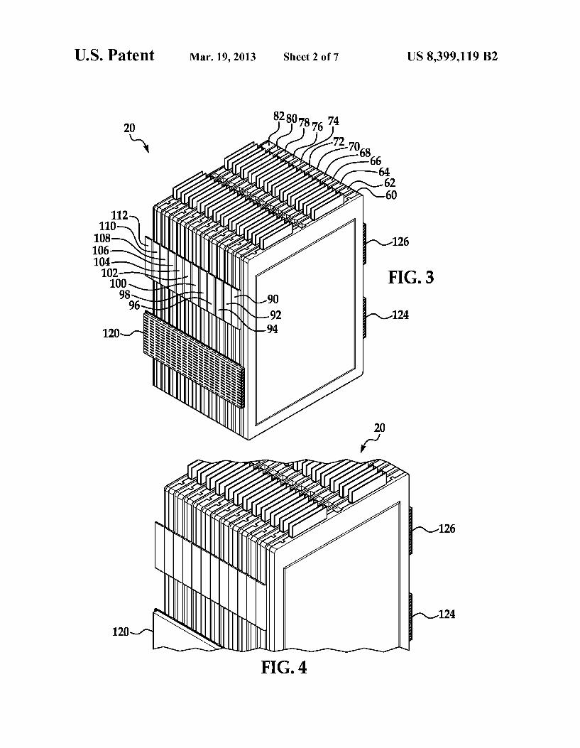
2 FIG. 3 is another schematic of the battery module of FIG.
2 having a cooling manifold removed therefrom; FIG. 4 is an enlarged schematic of a portion of the battery
module of FIG. 2; FIG. 5 is another enlarged schematic of a portion of the
battery module of FIG. 2; FIG. 6 is a schematic of an exploded view of a portion of the
battery module of FIG. 2; FIG. 7 is a schematic of two rectangular ring-shaped walls
Surrounding a cooling fin utilized in the battery module of FIG. 2:
FIG. 8 is schematic of the cooling fin of FIG. 7: FIG. 9 is a schematic of a cooling manifold utilized in the
battery module of FIG. 2; FIG. 10 is a cross-sectional Schematic of the cooling mani
fold of FIG. 9; FIG. 11 is another cross-sectional schematic of the cooling
manifold of FIG. 9; FIG. 12 is a flowchart of a method for cooling a battery
module in accordance with another exemplary embodiment; and
FIG. 13 is a schematic of another battery system in accor dance with another exemplary embodiment.
DETAILED DESCRIPTION OF EXEMPLARY EMBODIMENTS
Referring to FIG. 1, a battery system 10 for generating electrical power in accordance with an exemplary embodi ment is illustrated. The battery system 10 includes a battery module 20, a compressor 22, a condenser 24, conduits 28, 30. 32, a temperature sensor 36, a fan 38, and a microprocessor 40. An advantage of the battery module 20 is that the battery module utilizes cooling fins with external tab portions that contact a cooling manifold to transfer heat energy from bat tery cells to the cooling manifold to cool the battery cells.
For purposes of understanding, the term “fluid means either a liquid or a gas. For example, a fluid can comprise either a coolant or a refrigerant. Exemplary coolants include ethylene glycol and propylene glycol. Exemplary refrigerants include R-11, R-12, R-22, R-134A, R-407C and R-410A.
Referring to FIGS. 1-5, the battery module 20 is provided to generate a voltage therein. The battery module 20 includes battery cell assemblies 60, 62, 64, 66, 68, 70, 72, 74,76, 78, 80, 82, cooling fins 90,92,94, 96.98, 100,102,104,106,108, 110, 112, and cooling manifolds 120, 122, 124, 126. The battery cell assemblies 60, 62, 64, 66, 68, 70, 72, 74,
76, 78. 80, 82 are provided to generate an electrical voltage. Each of the battery cell assemblies 60, 62, 64, 66, 68,70, 72, 74, 76, 78,80, 82 have rectangular ring-shaped frame mem bers with engagement features which allow the battery cell assemblies to be coupled and secured together.
Referring to FIGS. 3 and 6, the battery cell assemblies each have a substantially similar structure. Accordingly, only the battery cell assemblies 60, 62 will be described in greater detail below. The battery cell assembly 60 includes a rectan gular ring-shaped frame member 140, battery cells 142, 144, and a rectangular ring-shaped frame member 146. Each of the rectangular ring-shaped frame members 140, 146 have engagement features which allow the frame members 140, 146 to be coupled and secured together. As shown, both of the battery cells 142, 144 are secured between the rectangular ring-shaped frame members 140, 146.
It should be noted that each of the battery cells have a substantially similar structure in the battery module 20. Accordingly, only the structure of the battery cell 142 will be described in greater detail below. The battery cell 142

US 8,399,119 B2 3
includes a body portion 160, a peripheral lip portion 162, and electrodes 164, 166 extending upwardly from the body por tion 160. The peripheral lip portion 162 extends around the periphery of the body portion 160. The electrodes 164, 166 extend outwardly from the body portion 150 and have a voltage generated therebetween. The electrodes of the battery cells of the battery module 20 can be electrically coupled together either in series or in parallel depending upon a desired voltage and current of the battery module 20. In one exemplary embodiment, each battery cell is a lithium-ion battery cell. In alternative embodiments, the battery cells could be nickel-cadmium battery cells or nickel metal hydride battery cells for example. Of course, other types of battery cells known to those skilled in the art could be utilized.
Referring to FIGS. 3,6,7, and 8, the cooling fins 90,92,94, 96, 98, 100, 102, 104, 106, 108, 110, 112 are provided to conduct heat energy from the battery cells into the cooling fins. Each of the cooling fins have a Substantially similar structure and are constructed from at least one of copper, aluminum, and steel. Accordingly, only the structure of the cooling fin 90 will be described in greater detail below. The cooling fin 90 includes a solid rectangular-shaped plate 180, tab portions 182, 184, 186,188, and plastic end portions 190, 192. The tab portions 182, 184 extend outwardly from a first
edge of the rectangular-shaped plate 180. Further, the tab portions 182, 184 are bent perpendicular in a first direction with respect to the plate 180, such that the tab portions 182, 184 are disposed against a side surface of the battery cell assembly 62. The tab portions 182, 184 are also perpendicular to a front surface of the battery cell 144. The tab portions 182, 184 contact the cooling manifolds 120, 122, respectively, such that the cooling manifolds 120, 122 conduct heatenergy away from the cooling fin 90. The tab portions 186, 188 extend outwardly from a second
edge of the rectangular-shaped plate 180. Further, the tab portions 186, 188 are bent perpendicular in a first direction with respect to the plate 180, such that the tab portions 186, 188 are disposed against a side surface of the battery cell assembly 62. The tab portions 186,188 are also perpendicular to a front surface of the battery cell 144. The tab portions 186, 188 contact the cooling manifolds 124, 126, respectively, Such that the cooling manifolds 124,126 conduct heatenergy away from the cooling fin 90. The plastic end portions 190,192 are disposed on a bottom
end and a top end, respectively, of the cooling fin 90. The plastic end portions 190, 192 are ultrasonically welded to the cooling fin 90.
Referring again to FIG. 6, the battery cell assembly 60 includes a rectangular ring-shaped frame member 210, bat tery cells 212, 214, and a rectangular ring-shaped frame member 216. Each of the rectangular ring-shaped frame members 210, 216 have engagement features which allow the frame members 210, 216 to be coupled and secured together. As shown, both of the battery cells 212, 214 are secured between the rectangular ring-shaped frame members 210, 216. Further, the frame members 146, 210 of the battery modules 60, 62, respectively, have engagement features which allow the frame members 146,210 to be coupled and secured together with the cooling fin 90 disposed therebe tWeen.
Referring to FIGS. 1, 2, 9, 10 and 11, the cooling manifolds 120, 122, 124, 126 are configured to allow fluid to flow therethrough to remove heat energy from cooling fins con tacting the cooling manifolds. The cooling manifolds 120, 122 are disposed on a first side of the battery module 20, and the cooling manifolds 124, 126 are disposed on a second side
10
15
25
30
35
40
45
50
55
60
65
4 of the battery module 20. Further, the cooling manifolds 120, 122,124, 126 are fluidly coupled between the conduits 28.30, such that a fluid flows from the conduit 28 into the cooling manifolds and then the fluid flows through the cooling mani folds into the conduit 30. The cooling manifolds 120, 122, 124, 126 are coupled to the battery cell assemblies utilizing known coupling devices or adhesives, such as screws or glues for example.
Referring to FIGS. 2, 9, 10 and 11, the structure of the cooling manifolds 120,122,124,126 are substantially similar to one another. Accordingly, only the structure the cooling manifold 120 will be discussed in greater detail below. The cooling manifold 120 includes an outer rectangular ring shaped wall 230 that extends in a first direction and inner walls 230, 232, 234, 236, 238,240, 242, 244, 246, 248,250, 252, 254, 256 disposed therein. The outer rectangular ring shaped wall 230 and the inner walls disposed inside an inte rior region defined by the wall 230 further define flow chan nels 270, 272, 274, 276, 278, 280, 282, 284, 286, 288, 290, 292, 294, 296 therein. The flow channels are configured to allow fluid the flow therethrough to extract heat energy from the cooling manifold 120. The cooling manifolds are con structed from a least one of copper and aluminum.
Referring to FIGS. 1 and 2, during operation, in one exem plary embodiment, heatenergy is conducted from the battery cell assemblies 60, 62, 64, 66, 68, 70, 72, 74,76, 78,80, 82 into the cooling fins 90,92, 94, 96, 98, 100, 102, 104, 106, 108, 110, 112 to cool the battery cell assemblies. The cooling fins further conduct heatenergy to the cooling manifolds 120, 122, 124, 126. A fluid flows through the cooling manifolds 120, 122, 124, 126 to conduct heat energy from the cooling manifolds into the fluid. The cooling fins 90,92,94, 96, 98,100,102,104,106,108,
110, 112 and the cooling manifolds 120, 122, 124, 126 main tain the battery cells within a desired temperature range, and in particular can maintain the battery cells at a temperature less than a threshold temperature level. In one exemplary embodiment, the desired temperature range is 15° Celsius 35° Celsius. In another exemplary embodiment, the threshold temperature level is 40° Celsius.
Referring again to FIG. 1, in one exemplary embodiment, the compressor 22 is configured to pump arefrigerant through the conduit 28 into cooling manifolds 120, 122, 124, 126 of the battery module 20 in response to a control signal from the microprocessor 40. The conduit 30 is also fluidly coupled to the cooling manifolds 120, 122, 124, 126 of the battery mod ule 20. The conduit 30 receives refrigerant from the cooling manifolds 120, 122, 124, 126 and routes the refrigerant to the condenser 24. The condenser 24 is provided to extract heat energy from
the refrigerant flowing therethrough to cool the refrigerant. As shown, a conduit 32 is fluidly coupled between the con denser 24 and the compressor 22. After exiting the condenser 24, the refrigerant is pumped through the conduit 32 to the compressor 22. The temperature sensor 36 is provided to generate a signal
indicative of a temperature level of the battery cells disposed in the housing 60 that is received by the microprocessor 40. The fan 38 is provided to urge air past the condenser 24 to
cool the condenser 24 in response to a control signal from the microprocessor 40. As shown, the fan 38 is disposed proxi mate to the condenser 24. The microprocessor 40 is provided to control operation of
the battery system 10. In particular, the microprocessor 40 is configured to generate a control signal for inducing the com pressor 22 to pump refrigerant through cooling manifolds of the battery module 20 when the signal from the temperature
US 8,399,119 B2 5
sensor 36 indicates a temperature level of the battery cells is greater than a predetermined temperature level. Further, the microprocessor 40 is configured to generate another control signal for inducing the fan 38 to blow air across the condenser 24 when the signal from the temperature sensor 36 indicates the temperature level of the battery cells is greater than the predetermined temperature level.
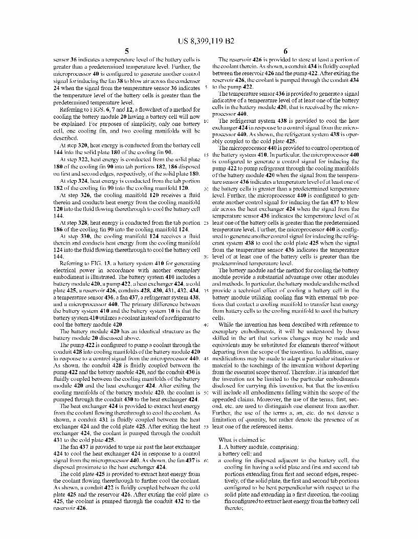
Referring to FIGS. 6, 7 and 12, a flowchart of a method for cooling the battery module 20 having a battery cell will now be explained. For purposes of simplicity, only one battery cell, one cooling fin, and two cooling manifolds will be described. At step 320, heat energy is conducted from the battery cell
144 into the solid plate 180 of the cooling fin 90. At step 322, heat energy is conducted from the solid plate
180 of the cooling fin 90 into tab portions 182, 186 disposed on first and second edges, respectively, of the solid plate 180.
At step 324, heatenergy is conducted from the tab portion 182 of the cooling fin 90 into the cooling manifold 120. At step 326, the cooling manifold 120 receives a fluid
therein and conducts heat energy from the cooling manifold 120 into the fluid flowing therethrough to cool the battery cell 144. At step 328, heatenergy is conducted from the tab portion
186 of the cooling fin 90 into the cooling manifold 124. At step 330, the cooling manifold 124 receives a fluid
therein and conducts heat energy from the cooling manifold 124 into the fluid flowing therethrough to cool the battery cell 144.
Referring to FIG. 13, a battery system 410 for generating electrical power in accordance with another exemplary embodiment is illustrated. The battery system 410 includes a battery module 420, a pump 422, aheat exchanger 424, a cold plate 425, a reservoir 426, conduits 428, 430, 431, 432, 434, a temperature sensor 436, a fan 437, a refrigerant system 438, and a microprocessor 440. The primary difference between the battery system 410 and the battery system 10 is that the battery system 410 utilizes a coolant instead of a refrigerant to cool the battery module 420. The battery module 420 has an identical structure as the
battery module 20 discussed above. The pump 422 is configured to pump a coolant through the
conduit 428 into cooling manifolds of the battery module 420 in response to a control signal from the microprocessor 440. As shown, the conduit 428 is fluidly coupled between the pump 422 and the battery module 420, and the conduit 430 is fluidly coupled between the cooling manifolds of the battery module 420 and the heat exchanger 424. After exiting the cooling manifolds of the battery module 420, the coolant is pumped through the conduit 430 to the heat exchanger 424. The heat exchanger 424 is provided to extract heat energy
from the coolant flowing therethrough to cool the coolant. As shown, a conduit 431 is fluidly coupled between the heat exchanger 424 and the cold plate 425. After exiting the heat exchanger 424, the coolant is pumped through the conduit 431 to the cold plate 425. The fan 437 is provided to urge air past the heat exchanger
424 to cool the heat exchanger 424 in response to a control signal from the microprocessor 440. As shown, the fan 437 is disposed proximate to the heat exchanger 424. The cold plate 425 is provided to extract heat energy from
the coolant flowing therethrough to further cool the coolant. As shown, a conduit 422 is fluidly coupled between the cold plate 425 and the reservoir 426. After exiting the cold plate 425, the coolant is pumped through the conduit 432 to the reservoir 426.
5
10
15
25
30
35
40
45
50
55
60
65
6 The reservoir 426 is provided to store at least a portion of
the coolant therein. As shown, a conduit 434 is fluidly coupled between the reservoir 426 and the pump 422. After exiting the reservoir 426, the coolant is pumped through the conduit 434 to the pump 422. The temperature sensor 436 is provided to generate a signal
indicative of a temperature level of at least one of the battery cells in the battery module 420, that is received by the micro processor 440. The refrigerant system 438 is provided to cool the heat
exchanger 424 in response to a control signal from the micro processor 440. As shown, the refrigerant system 438 is oper ably coupled to the cold plate 425. The microprocessor 440 is provided to control operation of
the battery system 410. In particular, the microprocessor 440 is configured to generate a control signal for inducing the pump 422 to pump refrigerant through the cooling manifolds of the battery module 420 when the signal from the tempera ture sensor 436 indicates a temperature level of at least one of the battery cells is greater than a predetermined temperature level. Further, the microprocessor 440 is configured to gen erate another control signal for inducing the fan 437 to blow air across the heat exchanger 424 when the signal from the temperature sensor 436 indicates the temperature level of at least one of the battery cells is greater than the predetermined temperature level. Further, the microprocessor 440 is config ured to generate another control signal for inducing the refrig erant system 438 to cool the cold plate 425 when the signal from the temperature sensor 436 indicates the temperature level of at least one of the battery cells is greater than the predetermined temperature level. The battery module and the method for cooling the battery
module provide a Substantial advantage over other modules and methods. In particular, the battery module and the method provide a technical effect of cooling a battery cell in the battery module utilizing cooling fins with external tab por tions that contact a cooling manifold to transfer heat energy from battery cells to the cooling manifold to cool the battery cells.
While the invention has been described with reference to exemplary embodiments, it will be understood by those skilled in the art that various changes may be made and equivalents may be substituted for elements thereof without departing from the scope of the invention. In addition, many modifications may be made to adapt a particular situation or material to the teachings of the invention without departing from the essential scope thereof. Therefore, it is intended that the invention not be limited to the particular embodiments disclosed for carrying this invention, but that the invention will include all embodiments falling within the scope of the appended claims. Moreover, the use of the terms, first, sec ond, etc. are used to distinguish one element from another. Further, the use of the terms a, an, etc. do not denote a limitation of quantity, but rather denote the presence of at least one of the referenced items.
What is claimed is: 1. A battery module, comprising: a battery cell; and a cooling fin disposed adjacent to the battery cell, the
cooling fin having a solid plate and first and second tab portions extending from first and second edges, respec tively, of the solid plate, the first and second tab portions configured to be bent perpendicular with respect to the Solid plate and extending in a first direction, the cooling fin configured to extract heatenergy from the battery cell thereto;

US 8,399,119 B2 7
a first cooling manifold that contacts the first tab portion of the cooling fin, the first cooling manifold having an outer rectangular ring-shaped wall extending in the first direc tion that defines at least one flow channel therethrough configured to receive a fluid therethrough, the first cool ing manifold configured to conduct heat energy from first tab portion of the cooling fin into the fluid flowing through the first cooling manifold to cool the battery cell; and
a second cooling manifold that contacts the second tab portion of the cooling fin, the second cooling manifold having at least one flow channel extending therethrough configured to receive a fluid therethrough, the second cooling manifold configured to conduct heat energy from the cooling fin into the fluid flowing through the second cooling manifold to cool the battery cell.
2. The battery module of claim 1, wherein the solid plate of the cooling fin is rectangular shaped.
10
15
3. The battery module of claim 1, wherein the cooling fin is 20 constructed of at least one of copper, aluminum, and steel.
8 4. The battery module of claim 1, wherein the first cooling
manifold is constructed of at least one of copper and alumi l
5. The battery module of claim 1, wherein the fluid is a coolant.
6. The battery module of claim 5, wherein the coolant comprises at least one of ethylene glycol and propylene gly col.
7. The battery module of claim 1, wherein the first cooling manifold further includes an inner wall disposed within an interior region defined by the outer rectangular ring-shaped wall, the inner wall and the outer rectangular ring-shaped wall defining at least another flow channel therethrough that is configured to receive the fluid therethrough.
8. The battery module of claim 1, further comprising first and second rectangular ring-shaped frame members config ured to hold the battery cell and the solid plate of the cooling fin therebetween.
9. The battery module of claim 1, wherein the fluid is a refrigerant.