(12) United States Patent (10) Patent No.: US … · 6,841,304 B2 1/2005 Michot et al. 2008.0020279...
22
(12) United States Patent Scott et al. US007875389B2 (10) Patent No.: US 7,875,389 B2 (45) Date of Patent: *Jan. 25, 2011 (54) LITHIUM-ION BATTERY (75) Inventors: Erik R. Scott, Maple Grove, MN (US); William G. Howard, Roseville, MN (US); Craig L. Schmidt, Eagan, MN (US) (73) Assignee: Medtronic, Inc., Minneapolis, MN (US) (*) Notice: Subject to any disclaimer, the term of this patent is extended or adjusted under 35 U.S.C. 154(b) by 0 days. This patent is Subject to a terminal dis claimer. (21) Appl. No.: 12/454,718 (22) Filed: May 21, 2009 (65) Prior Publication Data US 2009/0286151 A1 Nov. 19, 2009 Related U.S. Application Data (63) Continuation of application No. 10/979,040, filed on Oct. 29, 2004, now Pat. No. 7,811,705, and a continu ation of application No. 10/978,712, filed on Oct. 29, 2004, now Pat. No. 7,682,745. (51) Int. Cl. HOLM 4/58 (2010.01) (52) U.S. Cl. .............. 429/231.3; 429/231.1; 429/231.5; 429/224; 429/223; 429/221; 429/245; 429/249; 429/163 (58) Field of Classification Search .............. 429/231.3, 429/231, 1,231.5, 224, 223, 221, 245, 249, 429/163 See application file for complete search history. (56) References Cited U.S. PATENT DOCUMENTS 5,053,297 5,077,151 5,147,737 10, 1991 Yamahira et al. 12/1991 Yasuda et al. 9, 1992 Post et al. 3.462,303 A 8, 1969 Reber 3,791,867 A 2f1974 Broadhead et al. 3,864,167 A 2f1975 Broadhead et al. 3,898,096 A 8/1975 Herédy et al. 4,009,052 A 2/1977 Whittingham 4,048,397 A 9, 1977 Rothbauer 4,049,887 A 9/1977 Whittingham 4,113,921 A 9, 1978 Goldstein et al. 4,194,062 A 3, 1980 Carides et al. 4,202,702 A 5, 1980 NuSS 4,340,652 A 7, 1982 Raistricket al. 4,446,212 A 5, 1984 Kaun 4,464,447 A 8, 1984 Lazzari et al. 4,507,371 A 3/1985 Thackeray et al. 4,547.442 A 10, 1985 Besenhard et al. 4,555.456 A 11, 1985 Kanehori et al. 4,668,595 A 5, 1987 Yoshino et al. 4,764,437 A 8, 1988 Kaun 4,830,939 A 5, 1989 Lee et al. HT23 H 1/1990 Plichta et al. A A A 5,147,739 A 9, 1992 Beard 5,160,712 A 1 1/1992 Thackeray et al. 5,162,170 A 11/1992 Miyabayashi et al. 5,169,736 A 12/1992 Bittihn et al. 5,176,969 A 1/1993 Miyabayashi et al. 5, 187,033. A 2f1993 Koshiba 5,187,035 A 2/1993 Miyabayashi et al. 5,196,279 A 3, 1993 Tarascon 5,264,201 A 11/1993 Dahn et al. 5,284,721 A 2f1994 Beard 5,296,318 A 3, 1994 GoZdz et al. 5,300,373 A 4, 1994 Shackle 5,322,746 A 6/1994 Wainwright 5,340,666 A 8/1994 Tomantschger et al. 5,401,598 A 3/1995 Miyabayashi et al. 5,411,537 A 5/1995 Munshi et al. 5,418,090 A 5/1995 Koksbang et al. 5,498,489 A 3/1996 Dasgupta et al. 5,510,212 A 4/1996 Delnicket al. 5,525,441 A 6/1996 Reddy et al. 5,545,468 A 8, 1996 Koshiba et al. 5,547,785 A 8, 1996 Yumiba et al. A 5,569,553 10, 1996 Smesko et al. (Continued) FOREIGN PATENT DOCUMENTS EP O 567 149 B1 4f1992 (Continued) OTHER PUBLICATIONS U.S. Appl. No. 12/567,415, filed Sep. 25, 2009, Howard et al. (Continued) Primary Examiner Laura SWeiner (74) Attorney, Agent, or Firm Scott A. Marks; Foley & Lardner LLP (57) ABSTRACT A lithium-ion battery includes a positive electrode having an active material and a polymeric separator configured to allow electrolyte and lithium ions to flow between a first side of the separator and an opposite second side of the separator. The battery also includes a liquid electrolyte having a lithium salt dissolved in at least one non-aqueous solvent and a negative electrode having a lithium titanate active material. The posi tive electrode has a first capacity and the negative electrode has a second capacity that is less than the first capacity. 38 Claims, 7 Drawing Sheets
Transcript of (12) United States Patent (10) Patent No.: US … · 6,841,304 B2 1/2005 Michot et al. 2008.0020279...

(12) United States Patent Scott et al.
US007875389B2
(10) Patent No.: US 7,875,389 B2 (45) Date of Patent: *Jan. 25, 2011
(54) LITHIUM-ION BATTERY
(75) Inventors: Erik R. Scott, Maple Grove, MN (US); William G. Howard, Roseville, MN (US); Craig L. Schmidt, Eagan, MN (US)
(73) Assignee: Medtronic, Inc., Minneapolis, MN (US)
(*) Notice: Subject to any disclaimer, the term of this patent is extended or adjusted under 35 U.S.C. 154(b) by 0 days.
This patent is Subject to a terminal dis claimer.
(21) Appl. No.: 12/454,718
(22) Filed: May 21, 2009
(65) Prior Publication Data
US 2009/0286151 A1 Nov. 19, 2009
Related U.S. Application Data (63) Continuation of application No. 10/979,040, filed on
Oct. 29, 2004, now Pat. No. 7,811,705, and a continu ation of application No. 10/978,712, filed on Oct. 29, 2004, now Pat. No. 7,682,745.
(51) Int. Cl. HOLM 4/58 (2010.01)
(52) U.S. Cl. .............. 429/231.3; 429/231.1; 429/231.5; 429/224; 429/223; 429/221; 429/245; 429/249;
429/163 (58) Field of Classification Search .............. 429/231.3,
429/231, 1,231.5, 224, 223, 221, 245, 249, 429/163
See application file for complete search history. (56) References Cited
U.S. PATENT DOCUMENTS
5,053,297 5,077,151 5,147,737
10, 1991 Yamahira et al. 12/1991 Yasuda et al. 9, 1992 Post et al.
3.462,303 A 8, 1969 Reber 3,791,867 A 2f1974 Broadhead et al. 3,864,167 A 2f1975 Broadhead et al. 3,898,096 A 8/1975 Herédy et al. 4,009,052 A 2/1977 Whittingham 4,048,397 A 9, 1977 Rothbauer 4,049,887 A 9/1977 Whittingham 4,113,921 A 9, 1978 Goldstein et al. 4,194,062 A 3, 1980 Carides et al. 4,202,702 A 5, 1980 NuSS 4,340,652 A 7, 1982 Raistricket al. 4,446,212 A 5, 1984 Kaun 4,464,447 A 8, 1984 Lazzari et al. 4,507,371 A 3/1985 Thackeray et al. 4,547.442 A 10, 1985 Besenhard et al. 4,555.456 A 11, 1985 Kanehori et al. 4,668,595 A 5, 1987 Yoshino et al. 4,764,437 A 8, 1988 Kaun 4,830,939 A 5, 1989 Lee et al.
HT23 H 1/1990 Plichta et al. A A A
5,147,739 A 9, 1992 Beard
5,160,712 A 1 1/1992 Thackeray et al. 5,162,170 A 11/1992 Miyabayashi et al. 5,169,736 A 12/1992 Bittihn et al.
5,176,969 A 1/1993 Miyabayashi et al. 5, 187,033. A 2f1993 Koshiba
5,187,035 A 2/1993 Miyabayashi et al. 5,196,279 A 3, 1993 Tarascon 5,264,201 A 11/1993 Dahn et al.
5,284,721 A 2f1994 Beard 5,296,318 A 3, 1994 GoZdz et al.
5,300,373 A 4, 1994 Shackle
5,322,746 A 6/1994 Wainwright 5,340,666 A 8/1994 Tomantschger et al. 5,401,598 A 3/1995 Miyabayashi et al. 5,411,537 A 5/1995 Munshi et al.
5,418,090 A 5/1995 Koksbang et al. 5,498,489 A 3/1996 Dasgupta et al. 5,510,212 A 4/1996 Delnicket al.
5,525,441 A 6/1996 Reddy et al. 5,545,468 A 8, 1996 Koshiba et al. 5,547,785 A 8, 1996 Yumiba et al.
A 5,569,553 10, 1996 Smesko et al.
(Continued) FOREIGN PATENT DOCUMENTS
EP O 567 149 B1 4f1992
(Continued) OTHER PUBLICATIONS
U.S. Appl. No. 12/567,415, filed Sep. 25, 2009, Howard et al.
(Continued) Primary Examiner Laura SWeiner (74) Attorney, Agent, or Firm Scott A. Marks; Foley & Lardner LLP
(57) ABSTRACT
A lithium-ion battery includes a positive electrode having an active material and a polymeric separator configured to allow electrolyte and lithium ions to flow between a first side of the separator and an opposite second side of the separator. The battery also includes a liquid electrolyte having a lithium salt dissolved in at least one non-aqueous solvent and a negative electrode having a lithium titanate active material. The posi tive electrode has a first capacity and the negative electrode has a second capacity that is less than the first capacity.
38 Claims, 7 Drawing Sheets

US 7,875,389 B2 Page 2
U.S. PATENT DOCUMENTS 7,157,185 B2 1/2007 Marple 7, 177,691 B2 2/2007 Meadows et al.
5,576,608 A 1 1/1996 Nagai et al. 7,184,836 B1 2/2007 Meadows et al. 5,652,072 A 7, 1997 Lamanna 7,191,008 B2 3/2007 Schmidt et al. 5,670,862 A 9/1997 Lewyn 7,211,350 B2 5/2007 Amatucci 5,691,081 A 11/1997 Krause et al. 7,337,010 B2 2/2008 Howard et al. 5,744.258 A 4, 1998 Bai et al. 7,459,235 B2 12/2008 Choi et al. 5,744.264 A 4, 1998 Barker 7,524,580 B1 4/2009 Birke et al. 5,776,628 A 7, 1998 Kraft et al. 7,541,114 B2 * 6/2009 Ohzuku et al. .............. 429,224 5,882,218 A 3, 1999 Reimers 7,563,541 B2 7/2009 Howard et al. 5,888,665 A 3/1999 Bugga et al. 7,582,380 B1* 9/2009 Dunstan et al. .......... 429,231.3 5,891,592 A 4, 1999 Mao et al. 7,582,387 B2 9/2009 Howard et al. 5,911,947 A 6, 1999 Mitchell 7,818,068 B2 10/2010 Meadows et al. 5,935,724. A 8/1999 Spillman et al. 2001/0008725 A1 7, 2001. Howard 5,935,728 A 8/1999 Spillman et al. 2001/0012.590 A1 8, 2001 Ehrlich 5,968,681. A 10/1999 Miura et al. 2001/0021472 A1 9, 2001 Barker et al. 6,001,139 A 12/1999 Asanuma et al. 2001/0031401 A1 10, 2001 Yamawaki et al. 6,001,507 A 12/1999 Ono et al. 2003/0025482 A1 2/2003 Tsukamoto et al. 6,007,947 A 12/1999 Mayer 2003/0104282 A1 6/2003 Xing et al. 6,022,643 A 2/2000 Lee et al. 2003/O124423 A1 7/2003 Sasaki et al. 6,025,093 A 2, 2000 Herr 2003/O15741.0 A1 8/2003 Jarvis et al. 6,060,186 A 5/2000 Broussely 2003/021571.6 A1 11/2003 Suzuki et al. 6,067.474. A 5, 2000 Schulman et al. 2004/00231 17 A1 2/2004 Imachi et al. 6,120,938 A 9, 2000 Atsumi et al. 2004/0062989 A1 4/2004 Ueno et al. 6,139,518 A 10/2000 Mozsary et al. 2004/0072072 A1 4/2004 Suzuki et al. 6,165,638 A 12/2000 Spillman et al. 2004/0096745 A1 5, 2004 Shibano et al. 6, 165,646 A 12/2000 Takada et al. ............ 429,231.3 2004/O147971 A1 7/2004 Greatbatch et al. 6,171,729 B1 1/2001 Gan et al. 2004/0147972 A1 7/2004 Greatbatch et al. 6,203,947 B1 3/2001 Peled et al. 2004/0158296 A1 8/2004 Greatbatch et al. 6,203,994 B1 3/2001 Epps et al. 2004/0168307 A1 9/2004 Hong 6,207,327 B1 3/2001 Takada et al. 2004/0176818 A1 9, 2004 Wahlstrand et al. 6,221,531 B1 4/2001 Vaughey et al. 2004/0197657 A1 10/2004 Spitler et al. 6,228,536 B1 52001 Wasynczuk 2004/020915.6 A1 10, 2004 Ren et al. 6,258.473 B1 72001 Spillman et al. 2005/0031919 A1 2/2005 Ovshinsky et al. 6,265,100 B1, 7/2001 Saaski et al. 2005, OO69777 A1 3, 2005 Takami et al. 6,274,271 B1 8/2001 Koshiba et al. 2005. O13.0043 A1 6, 2005 Gao et al. 6,287,721 B1 9/2001 Xie et al. 2005, 0147889 A1 7, 2005 Ohzuku et al. 6,316,145 B1 1 1/2001 Kida et al. 2005, 0164082 A1 7, 2005 Kishi et al. 6,335,115 B1 1/2002 Meissner 2005/024471.6 A1 1 1/2005 Ogawa et al. 6,352,798 B1 3, 2002 Lee et al. 2006.0024582 A1 2/2006 Li et al. 6,365,301 B1 * 4/2002 Michot et al. ............... 429,324 2006, 004649 A1 3/2006 Yong et al. 6,372.384 B1 4/2002 Fujimoto et al. 2006/0068282 A1 3/2006 Kishi et al. 6,379,842 B1 4/2002 Mayer 2006/0093871 A1 5.2006 Howard et al. 6,451.480 B1 9/2002 Gustafson et al. 2006/0093872 A1 5.2006 Howard et al. 6,453,198 B1 9/2002 Torgerson et al. 2006/0093873 A1 5.2006 Howard et al. 6,461,751 B1 10/2002 Boehm et al. 2006/0093894 A1 5.2006 Scott et al. 6,461,757 B1 10/2002 Sasayama et al. 2006/0093.913 A1 5.2006 Howard et al. 6,475,673 B1 1 1/2002 Yamawaki et al. 2006/0093.917 A1 5.2006 Howard et al. 6,489,062 B1 12/2002 Watanabe 2006/0093.921 A1 5.2006 Scott et al. 6,503,662 B1 1/2003 Hamamoto et al. 2006/0093.923 A1 5, 2006 Howard et al. 6,528.208 B1 3/2003 Thackeray et al. 2006/0216612 A1 9, 2006 Jambunathan et al. 6,553,263 B1 4/2003 Meadows et al. 2006/0234125 A1 10, 2006 Valle 6,596,439 B1 7/2003 Tsukamoto et al. 2006/025 1968 A1 11/2006 Tsukamoto et al. 6,645,670 B2 11/2003 Gan 2007/0009801 A1 1/2007 Inagaki et al. 6,645,675 B1 1 1/2003 Munshi 2007/0059587 A1 3, 2007 Kishi et al. 6,673,493 B2 1/2004 Gan et al. 2007, OO72085 A1 3, 2007 Chen et al. 6,677,083 B2 1/2004 Suzuki et al. 2007, OO77496 A1 4, 2007 Scott et al. 6,706,445 B2 3/2004 Barker et al. 2007/01 11099 A1 5/2007 Nanjundaswamy et al. 6,720,112 B2 4/2004 Barker et al. 2007/0134556 A1 6, 2007 Sano et al. 6,730.437 B2 5/2004 Leising et al. 2007/0162083 A1 7, 2007 Schmidt et al. 6,737,191 B2 5/2004 Gan et al. 2007/0233.195 A1 10, 2007 Wahlstrand et al. 6,759,168 B2 7/2004 Yamasaki et al. 2007/0239221 A1 10, 2007 Kast et al. 6,761,744 B1 7/2004 Tsukamoto et al. 2007/0248881 A1 10, 2007 Scott et al. 6,777, 132 B2 8/2004 Barker et al. 2007/0284159 A1 12/2007 Takami et al. 6.824,920 B1 11/2004 Iwamoto et al. 2008.0020278 A1 1/2008 Schmidt et al. 6,841,304 B2 1/2005 Michot et al. 2008.0020279 A1 1/2008 Schmidt et al. 6,849,360 B2 2/2005 Marple 2008.OO26297 A1 1/2008 Chen et al. 6,905,795 B2 6/2005 Jung et al. 2008/0044728 A1 2/2008 Schmidt et al. 6,905,796 B2 6/2005 Ishida et al. 2009.0035662 A1 2/2009 Scott et al. 6,908,711 B2 6, 2005 Fauteux et al. 6,942,949 B2 9, 2005 Besenhard et al. FOREIGN PATENT DOCUMENTS 7,029,793 B2 4/2006 Nakagawa et al. 7,101,642 B2 9/2006 Tsukamoto et al. EP O 732 761 A2 3, 1996

US 7,875,389 B2 Page 3
EP O982 790 A1 3, 1998 EP 1 O18773 A1 4f1999 EP 1 014. 465 A1 12/1999 EP 1069 635 A1 5, 2000 EP 1282 180 A1 T 2001 EP 1487 039 A1 12/2004 EP 1722 439 A1 11, 2006 JP 56-136462 A 10, 1981 JP 57-01.1476 A 1, 1982 JP 63-1708 B2 1, 1982 JP 57-152669 A 9, 1982 JP O2-309568 A 12/1990 JP 6-275263. A 9, 1994 JP 10-027626 A 1, 1998 JP 2000-156229 A 6, 2000 JP 2000-195499. A T 2000 JP 2001-1267.56 A 5, 2001 JP 2001-185141 A T 2001 WO WO97,06569 A1 2, 1997 WO WO 97/48141 A1 12/1997 WO WOOOf 1795.0 A1 3, 2000 WO WOO1/3365.6 A1 5, 2001 WO WO O2/O9215 A2 1, 2002 WO WOO2,21628 A1 3, 2002 WO WOO2,395.24 A1 5, 2002 WO WO 02/069414 A2 9, 2002 WO WO O2/O95845 A1 11, 2002 WO WO 03/044880 A1 5, 2003 WO WOO3,O75371 A2 9, 2003 WO WOO3,O75376 * 9/2003 WO WOO3,O90293 A2 10, 2003 WO WO 2006/05OO22 A2 5, 2006 WO WO 2006/05OO23 A2 5, 2006 WO WO 2006. O50098 A1 5, 2006 WO WO 2006/05.0099 A1 5, 2006 WO WO 2006/05O100 A2 5, 2006 WO WO 2006/050117 A2 5, 2006 WO WO 2006/064344 A2 6, 2006
OTHER PUBLICATIONS
U.S. Appl. No. 12/564,818, filed Sep. 22, 2009, Howard et al. U.S. Appl. No. 12/511.942, filed Jul. 29, 2009, Howard et al. U.S. Appl. No. 12/510,857, filed Jul. 28, 2009, Howard et al. U.S. Appl. No. 12/429,061, filed Apr. 23, 2009, Howard et al. U.S. Appl. No. 12/112,979, filed Apr. 30, 2008, Scott et al. “Battery Materials—Ceramic Anode Material for 2.4V Lithium-Ion Batteries' EXM 1037 Li TiO (1 page), available at least by Oct. 25, 2004. Ariyoshi, et al., “Three-Volt Lithium-Ion Battery with LiNi MnO, and the Zero-Strain Insertion Material of LiLi TiO,”, Journal of Power Sources, 119-121, 2003, pp. 959-963. Belharouaket al., “On the Safety of the Li TiO/LiMnO, Lithium Ion Battery System.” (ECS) Journal of The Electrochemical Society, 2007, pp. A1083-A1087, vol. 154, No. 12. Brohan et al., Properties Physiques Des Bronzes MTiO.(B), Solid State Ionics, vols. 9 and 10, 1983, (C) North Holland Publishing Company, pp. 419-424. Cava et al., The Crystal Structures of the Lithium-Inserted Metal Oxides Lio, TiO, Anatase, Li TiO, Spinel, and Li TiO, Journal of Solid State Chemistry, vol.53, Jan. 1984 (C) Academic Press, Inc., pp. 64-75.
Christensen et al., “Optimization of Lithium Titanate Electrodes for High-Power Cells.” (ECS) Journal of The Electrochemical Society, 2006, pp. A560-A565, vol. 153, No. 3. Colbow et al., Structure and Electrochemistry of the Spinel Oxides LiTiO, and Li TiO, Journal of Power Sources, vol. 26, 1989, C) Elsevier Sequoia, pp. 397-402. Dahn et al., “Combinatorial Study of Sn1-xCox (0-3x<0.6) and SnO. 55Co0.451-yCy (0-y-0.5) Alloy Negative Electrode Materials for Li-Ion Batteries,” Journal of Electrochemical Society, vol. 153,2006, pp. A361-A365.
Fauteux et al., “Rechargeable lithium battery anodes: alternatives to metallic lithium.” Journal of Applied Electrochemistry, vol. 23, 1993, pp. 1-10. Ferg et al. “Spinel Anodes for Lithium-Ion Batteries'. J. Electrochem. Soc. vol. 141 #11, 1994, pp. L147-L150. FMC Lithium, CAS No. 74389-93-2, “Stabilized Lithium Metal Powder” Product Specification, Copyright 2001 FMC Corporation (2 pages). Guerfi, et. Al., “Nano Electronically Conductive Titanium-Spinel as Lithium Ion Storage Negative Electrode'. Journal of Power Sources, 126, 2004, pp. 163-168. Guyomard et al., “New amorphous oxides as high capacity negative electrodes for lithium6 batteries the LixMV04 (M-Ni, Co, Cd, Zn; 1 <x<8) series,” Journal of Power Sources, vol. 68, 1997, pp. 692-697. Jansen, et. Al., “Development of A High-Power Lithium-Ion Bat tery”, Journal of Power Sources, 81-82, 1999, pp. 902-905. Jarvis et al., “A Li-Ion Cell Containing A Non-Lithiated Cathode'. Abs. 182, IMLB 12 Meeting (1 page). Kavan, et al., Proof of Concept—Li TiO2, Electrochemical and Solid State Letters, 2002, vol. 5, A39-A42, p. 13. Linden, David, Editor in Chief, Handbook of Batteries, Second Edi tion, McGraw-Hill, NY, 1995, 6 pages. Mikula et al., Photoelectrochemical Properties of Anodic TiO, Lay ers Prepared by Various Current Densities, J. Electrochemical Soci ety, vol. 139, No. 12, Dec. 1992 C. The Electrochemical Society, Inc., pp. 3470-3474. Murphy et al., “Topochemical Reactions of Rutile Related Structures with Lithium”. Mat. Res. Bull, vol. 13, No. 12, 1978, (C) Pergamon Press, Inc., pp. 1395-1402. Murphy et al., Lithium Insertion in Anatase: A New Route to the Spinel LiTiO, Revue De Chimie Minerale, vol. 19, 1982, 9 pgs. Murphy et al., Ternary Li, TiO, Phases from Insertion Reactions, Solid State Ionics, vols. 9 & 10, 1983 (C) North-Holland Publishing Company, pp. 413-418. Nakahara, et al. "Preparation of Particulate Li TiO, Having Excel lent Characteristics ASAn Electrode Active Material For Power Stor age Cells'. Journal of Power Sources, 117, 2003, pp. 131-136. New Li Ti-O Anode Material of Sid-Chemie AG for Lithium Ion Batteries, Sid-Chemie EXM 1037 Li TiO, Product Specifica tion (2 pages). Ohzuku et al., “Why transition metal (di)oxides are the most attrac tive materials for batteries.” Solid State Ionics, vol. 69, 1994, pp. 201-211.
Ohzuku et al., “Lithium-Ion Batteries of LiLi TiO, With Selected Positive-Electrode Materials for Long-Life Power Applica tion'. Abs. 23, IMLB 12 Meeting (1 page). OhZuku et al., Zero-Strain Insertion Material of Li Li Tis IO for Rechargeable Lithium Cells, Electrochemical Science and Technol ogy, J. Electrochem Soc., vol. 142, No. 5, May 1995 (C) The Electro chemical Society, Inc., 5 pages. Ohzuku, Extended Abstracts from the Seventh Intl Meeting on Li Batteries, Boston, MA, May 15-20, 1994, pp. 111-112. Peramunage et al., Preparation of Micro-Sized Li TiO, and Its Electrochemistry in Polyacrylonitrile Electrolye-Based Lithium Cells, Technical Papers, Electrochemical Science and Technology, J. ElectrochemSoc., vol. 145, No. 8, Aug. 1998 (C). The Electrochemical Society, Inc., 7 pages. Poizot et al., “Nano-sized transition-metal oxides as negative-elec trode materials for lithium-ion batteries.” Nature, vol. 407, 2000, cover and pp. 496-499. Prosini, et. Al. “LiTiO. As Anode in All-Solid-State, Plastic, Lithium-Ion Batteries for Low-Power Applications' Solid State Ion ics, 144, 2001, pp. 185-192. Sasaki et al., Layered Hydrous Titanium Dioxide: Potassium Ion Exchange and Structural Characterization, Inorganic Chemistry, vol. 24, No. 14, (C) 1985 American Chemical Society, pp. 2265-2271. Sawai, et al., Factors Affecting Rate Capability of a Lithium-ion Battery with Li Li TiO, and LiCoNiO, Abs. 75, 205' Meeting, 1 page. Scrosati, "Low Voltage Lithium-Ion Cells'. Advances in Lithium-Ion Batteries Kluwer Academic/Plenum Publishers, pp. 289-308.

US 7,875,389 B2 Page 4
Singhal, et al. “Nanostructured Electrodes for Next Generation Rechargeable Electrochemical Devices”, Journal of Power Sources, 129, 2004, pp. 38-44. Sun et al., “The Compatibility of a Boron-Based Anion Receptor with the Carbon Anode in Lithium-Ion Batteries.” (ECS) Electrochemical and Solid-State Letters, 2003, pp. A43-A46, vol. 6, No. 2. Sun et al., “Using a Boron-Based Anion Receptor Additive to Improve the Thermal Stability of LiPF-Based Electrolyte for Lithium Batteries.” (ECS) Electrochemical and Solid-State Letters, 2002, pp. A248-A251, vol. 5, No. 11. Trifonova et al., “Sn-Sb and Sn-Bi Alloys as Anode Materials for Lithium-Ion Batteries.” Ionics, vol. 8, 2002, cover and pp. 321-328. Wang et al., Li Insertion and Ion Exchange Reactions in the Ionic Conducting TI2(M.Ti)8O16 Phases with Hollandite-Type Structure, Technical Papers, Solid-State Science and Technology, J. ElectrochemSoc., vol. 138, No. 1, Jan. 1991, (C). The Electrochemical Society, Inc., pp. 166-172. Wang et al., Novel Eletrolytes for Nanocrystalline Li TiO, Based High Power Lithium Ion Batteries, 1 page. Winter et al., “Insertion Electrode Materials for Rechargeable Lithium Batteries.” Advanced Materials, vol. 10, 1998, pp. 725-763. Winter et al., “Electrochemical lithiation of tin and tin-based intermetallics and composites.” Electrochimica Acta, vol. 45, 1999, pp. 31-50. Zaghib, etal, “Electrochemical Study of Li TiO. As Negative Elec trode for Li-Ion Polymer Rechargeable Batteries”, Journal of Power Sources, 81-82, 1999, pp. 300-305. International Search Report for PCT/US2005/038761, date of mail ing Oct. 4, 2006, 2 pages. International Search Report for PCT/US2005/038762, date of mail ing Oct. 2, 2006, 2 pages. International Search Report for PCT/US2005/038942, date of mail ing, Mar. 2, 2006, 3 pages. International Search Report for PCT/US2005/038943, date of mail ing, Mar. 16, 2006, 3 pages. International Search Report for PCT/US2005/038944, date of mail ing, Mar. 31, 2006, 3 pages. International Search Report for PCT/US2005/038970, date of mail ing Oct. 25, 2006, 3 pages. International Search Report and Written Opinion for Application No. PCT/US2008/066809, mailing date Oct. 29, 2008, 8 pages. International Search Report and Written Opinion for Application No. PCT/US2008/066801, mailing date Oct. 29, 2008, 10 pages. International Search Report and Written Opinion for Application No. PCT/US2008/066803, date of mailing Oct. 7, 2008, 12 pages. International Search Report and Written Opinion for Application No. PCT/US2008/082598, date of mailing Feb. 18, 2009, 11 pages. Amendment and Reply for U.S. Appl. No. 12/240,652, dated Sep. 2, 2009, 13 pages. Non-Final Office Action for U.S. Appl. No. 12/240,652, dated Jun. 2, 2009, 6 pages. Preliminary Amendment for U.S. Appl. No. 12/240,652, dated Oct. 7, 2008, 3 pages. Advisory Action for U.S. Appl. No. 10/978,712, dated Aug. 27, 2009, 3 pages.
Reply and Amendment for U.S. Appl. No. 10/978,712, dated Aug. 14. 2009, 14 pages. Final Office Action for U.S. Appl. No. 10/978,712, dated Jun. 17, 2009, 11 pages. Reply and Amendment for U.S. Appl. No. 10/978,712, datedMar. 24. 2009, 16 pages. Non-Final Office Action for U.S. Appl. No. 10/978,712, dated Jan.5, 2009, 16 pages. Request for Continued Examination (RCE), Reply and Amendment and Terminal Disclaimers for U.S. Appl. No. 10/978,712, dated Dec. 8, 2008, 20 pages. Final Office Action for U.S. Appl. No. 10/978,712, dated Oct. 9, 2008, 7 pages. Reply and Amendment and Declaration Under 1.131 for U.S. Appl. No. 10/978,712, dated Jul. 16, 2008, 36 pgs. Non-Final Office Action for U.S. Appl. No. 10/978,712, dated Apr. 10, 2008, 12 pages. Preliminary Amendment for U.S. Appl. No. 10/978,712, filed with the USPTO on Oct. 29, 2004, 11 pages. Non-Final Office Action for U.S. Appl. No. 10/979,040, dated Sep. 30, 2009, 7 pages. Request for Continued Examination (RCE) for U.S. Appl. No. 10/979,040, dated Sep. 11, 2009, 3 pages. Advisory Action for U.S. Appl. No. 10/979,040, dated Aug. 24, 2009, 3 pages. Reply and Amendment for U.S. Appl. No. 10/979,040, dated Aug. 17. 2009, 13 pages. Final Office Action for U.S. Appl. No. 10/979,040, dated Jun. 16, 2009, 10 pages. Reply and Amendment for U.S. Appl. No. 10/979,040, datedMar. 24. 2009, 12 pages. Non-Final Office Action for U.S. Appl. No. 10/979,040, dated Jan. 12, 2009, 10 pages. Request for Continued Examination (RCE) and Reply and Amend ment for U.S. Appl. No. 10/979,040, dated Dec. 11, 2008, 16 pages. Final Office Action for U.S. Appl. No. 10/979,040, dated Sep. 19, 2008, 10 pages. Reply and Amendment and Declaration Under 1.131 for U.S. Appl. No. 10/979,040, dated Jul. 16, 2008, 33 pages. Non-Final Office Action for U.S. Appl. No. 10/979,040, dated Apr. 2, 2008, 8 pages. Preliminary Amendment for U.S. Appl. No. 10/979,040, filed with the USPTO on Mar. 4, 2005, 11 pages. Notice of Allowance for U.S. Appl. No. 1 1/260,853, dated Aug. 5, 2009, 7 pages. Reply and Amendment for U.S. Appl. No. 1 1/260,853, dated Jun. 4. 2009, 14 pages. Non-Final Office Action for U.S. Appl. No. 1 1/260,853, datedMar. 5, 2009, 13 pages. Final Office Action for U.S. Appl. No. 12/240,652, dated Aug. 25. 2010, 7 pages. Amendment and Reply and Terminal Disclaimer for U.S. Appl. No. 12/240,652, filed Sep. 23, 2010, 13 pages. Advisory Action for U.S. Appl. No. 12/240,652, dated Sep. 30, 2010, 3 pages.
* cited by examiner
US 7,875,389 B2 Sheet 1 of 7 Jan. 25, 2011 U.S. Patent
<!--------------------------------------------- E5D}+\/HOSIO

US 7,875,389 B2 Sheet 2 of 7 Jan. 25, 2011 U.S. Patent
% 00
+-----------------------+---+---+-------------------~~~~---------------------+-------------------------------*$$$ w wº??
001
ISA elueO
U.S. Patent Jan. 25, 2011 Sheet 3 of 7 US 7,875,389 B2
S
O D
CN
s S.

US 7,875,389 B2 Sheet 5 Of 7 Jan. 25, 2011 U.S. Patent
90-8/NOW – 7– 0 ||
uæquun.N 310KO
| 00°0 ZOO” O W GOO’ O
(uu-eedule) Aloedeo efieuoSIO

Jan. 25, 2011 Sheet 6 of 7 US 7,875,389 B2
s
U.S. Patent
23.
4.
3S
2. s
rest Tire (set)
FGURE 7
s s

U.S. Patent Jan. 25, 2011 Sheet 7 Of 7 US 7,875,389 B2
s
o
r

US 7,875,389 B2 1.
LITHIUM-ON BATTERY
CROSS-REFERENCE TO RELATED APPLICATIONS
The present application is a Continuation of U.S. patent application Ser. No. 10/979,040 filed Oct. 29, 2004 (now U.S. Pat. No. 7,811,705) and is also a Continuation of U.S. patent application Ser. No. 10/978,712 filed Oct. 29, 2004 (now U.S. Pat. No. 7,682,745). The entire disclosures of U.S. patent application Ser. No. 10/979,040 and U.S. patent application Ser. No. 10/978,712 (now U.S. Pat. No. 7,682,745) are incor porated herein by reference.
BACKGROUND
The present invention relates generally to the field of lithium-ion batteries. Specifically, the present invention relates to lithium-ion batteries that are relatively tolerant to over-discharge conditions.
Lithium-ion batteries include a positive current collector (e.g., aluminum Such as an aluminum foil) having an active material provided thereon (e.g., LiCoO) and a negative cur rent collector (e.g., copper Such as a copper foil) having an active material (e.g., a carbonaceous material Such as graph ite) provided thereon. Together the positive current collector and the active material provided thereon are referred to as a positive electrode, while the negative current collector and the active material provided thereon are referred to as a nega tive electrode.
FIG. 1 shows a schematic representation of a portion of a lithium-ion battery 10 such as that described above. The battery 10 includes a positive electrode 20 that includes a positive current collector 22 and a positive active material 24, a negative electrode 30 that includes a negative current col lector 32 and a negative active material 34, an electrolyte material 40, and a separator (e.g., a polymeric microporous separator, not shown) provided intermediate or between the positive electrode 20 and the negative electrode 30. The elec trodes 20, 30 may be provided as relatively flat or planar plates or may be wrapped or wound in a spiral or other configuration (e.g., an oval configuration). The electrode may also be provided in a folded configuration.
During charging and discharging of the battery 10, lithium ions move between the positive electrode 20 and the negative electrode 30. For example, when the battery 10 is discharged, lithium ions flow from the negative electrode 30 to the to the positive electrode 20. In contrast, when the battery 10 is charged, lithium ions flow from the positive electrode 20 to the negative electrode 30.
FIG. 2 is a graph 100 illustrating the theoretical charging and discharging behavior for a conventional lithium-ion bat tery. Curve 110 represents the electrode potential versus a lithium reference electrode for a positive electrode that includes an aluminum current collector having a LiCoO. active material provided thereon, while curve 120 represents the electrode potential versus a lithium reference electrode for a negative electrode that includes a copper current collec tor having a carbonaceous active material provided thereon. The difference between curves 110 and 120 is representative of the overall cell voltage. As shown in FIG. 2, upon initial charging to full capacity,
the potential of the positive electrode, as shown by curve 110. increases from approximately 3.0 volts to a point above the corrosion potential of copper used to form the negative elec trode (designated by dashed line 122). The potential of the negative electrode decreases from approximately 3.0 volts to
10
15
25
30
35
40
45
50
55
60
65
2 a point below the decomposition potential of the LiCoO. active material provided on the aluminum current collector (designated by dashed line 112). Upon initial charging, the battery experiences an irreversible loss of capacity due to the formation of a passive layer on the negative current collector, which may be referred to as a solid-electrolyte interface (“SEI”). The irreversible loss of capacity is shown as a ledge or shelf 124 in curve 120. One difficulty with conventional lithium-ion batteries is
that when such a battery is discharged to a point near Zero volts, it may exhibit a loss of deliverable capacity and corro sion of the negative electrode current collector (copper) and possibly of the battery case, depending on the material used and the polarity of the case. As shown in FIG. 2, after initial charging of the battery, a Subsequent discharge of the battery in which the voltage of the battery approaches zero volts (i.e., Zero percent capacity) results in a negative electrode potential that follows a path designated by dashed line 126. As shown in FIG. 2, the negative electrode potential levels off or pla teaus at the copper corrosion potential of the negative current collector (approximately 3.5 Volts for copper and designated by dashed line 122 in FIG. 2). The point at which the curves 110 and 120 cross is some
times referred to as the Zero Voltage crossing potential, and corresponds to a cell Voltage that is equal to Zero (i.e., the difference between the two curves equals Zero at this point). Because of the degradation of the copper current collector which occurs at the copper corrosion potential, the copper material used for the negative current collector corrodes before the cell reaches a Zero Voltage condition, resulting in a battery that exhibits a loss of deliverable capacity.
While FIG. 2 shows the theoretical charging and discharg ing behavior of a battery that may experience corrosion of the negative current collector when the battery approaches a Zero Voltage configuration, it should be noted that there may also be cases in which the active material on the positive current collector may degrade in near-Zero-Voltage conditions. In Such cases, the theoretical charging and discharging potential of the positive electrode versus a lithium reference electrode would decrease to the decomposition potential of the positive active material (shown as line 112 in FIG. 2), at which point the positive active material would decompose, resulting in potentially decreased protection against future over-dis charge conditions.
Because damage to the lithium-ion battery may occur in the event of a low Voltage condition, conventional lithium-ion batteries may include protection circuitry and/or may be uti lized in devices that include protection circuitry which sub stantially reduces the current drain from the battery (e.g., by disconnecting the battery). The medical device industry produces a wide variety of
electronic and mechanical devices for treating patient medi cal conditions. Depending upon the medical condition, medi cal devices can be surgically implanted or connected exter nally to the patient receiving treatment. Clinicians use medical devices alone or in combination with drug therapies and Surgery to treat patient medical conditions. For some medical conditions, medical devices provide the best, and Sometimes the only, therapy to restorean individual to a more healthful condition and a fuller life.
It may be desirable to provide a source of battery power for Such medical devices, including implantable medical devices. In such cases, it may be advantageous to provide a battery that may be recharged. It may also be advantageous to provide a battery that may be discharged to a near Zero Voltage condition without substantial risk that the battery may be damaged (e.g., without corroding one of the electrodes or the

US 7,875,389 B2 3
battery case, decomposing the positive active material, etc.) such that the performance of the battery is degraded in sub sequent charging and discharging operations.
It would be advantageous to provide a battery (e.g., a lithium-ion battery) that may be discharged to near Zero volts without producing a Subsequent decrease in the amount of deliverable capacity or producing a corroded negative elec trode or battery case. It would also be advantageous to pro vide a battery that compensates for the irreversible loss of capacity resulting from initial charging of the battery to allow the battery to be used in near Zero voltage conditions without significant degradation to battery performance. It would also be advantageous to provide a medical device (e.g., an implantable medical device) that utilizes a battery that includes any one or more of these or other advantageous features.
SUMMARY
An exemplary embodiment relates to a lithium-ion battery comprising a positive electrode comprising an active material and a polymeric separator configured to allow electrolyte and lithium ions to flow between a first side of the separator and an opposite second side of the separator. The battery also com prises a liquid electrolyte comprising a lithium salt dissolved in at least one non-aqueous solvent and a negative electrode comprising a lithium titanate active material. The positive electrode has a first capacity and the negative electrode has a second capacity that is less than the first capacity.
Another exemplary embodiment relates to a lithium-ion battery comprising a positive electrode having a first capacity and comprising a foil current collector and an active material comprising at least one material selected from the group consisting of LiCoO, LiMn2O4, LiCo, Ni-O, where X is between approximately 0.05 and 0.8, LiNiCo, MnO, LiAlCo, Ni--O, where X is between approximately 0.05 and 0.3 and y is between approximately 0.1 and 0.3, and LiTiCo, Ni--O, where X is between approximately 0.05 and 0.3 and y is between approximately 0.1 and 0.3. The battery also includes an electrolyte and a negative electrode having a second capacity that is not greater than the first capacity, the negative electrode comprising a foil current collector and a lithium titanate active material.
Another exemplary embodiment relates to a lithium-ion battery comprising a positive electrode having a first capacity and comprising a foil current collector and an active material comprising at least one material selected from the group consisting of LiCoO, LiMn2O4, LiCo, Ni-O, where X is between approximately 0.05 and 0.8, LiNiCo, MnO, LiAlCo, Ni--O, where X is between approximately 0.05 and 0.3 and y is between approximately 0.1 and 0.3, and LiTiCo, Ni--O, where X is between approximately 0.05 and 0.3 and y is between approximately 0.1 and 0.3. The battery also includes a liquid electrolyte and a negative elec trode having a second capacity that is not greater than the first capacity. The negative electrode comprises a foil current col lector and a Li TiO2 active material. A porous polymeric separator is provided between the positive electrode and the negative electrode.
BRIEF DESCRIPTION OF THE DRAWINGS
FIG. 1 is a schematic cross-sectional view of a conven tional lithium-ion battery.
FIG. 2 is a graph illustrating the theoretical charging and discharging behavior for a conventional lithium-ion battery such as that shown schematically in FIG. 1.
5
10
15
25
30
35
40
45
50
55
60
65
4 FIG.3 is a schematic cross-sectional view of a portion of a
lithium-ion battery according to an exemplary embodiment. FIG. 4 is a graph illustrating the theoretical charging and
discharging behavior for a lithium-ion battery Such as that shown in FIG. 3.
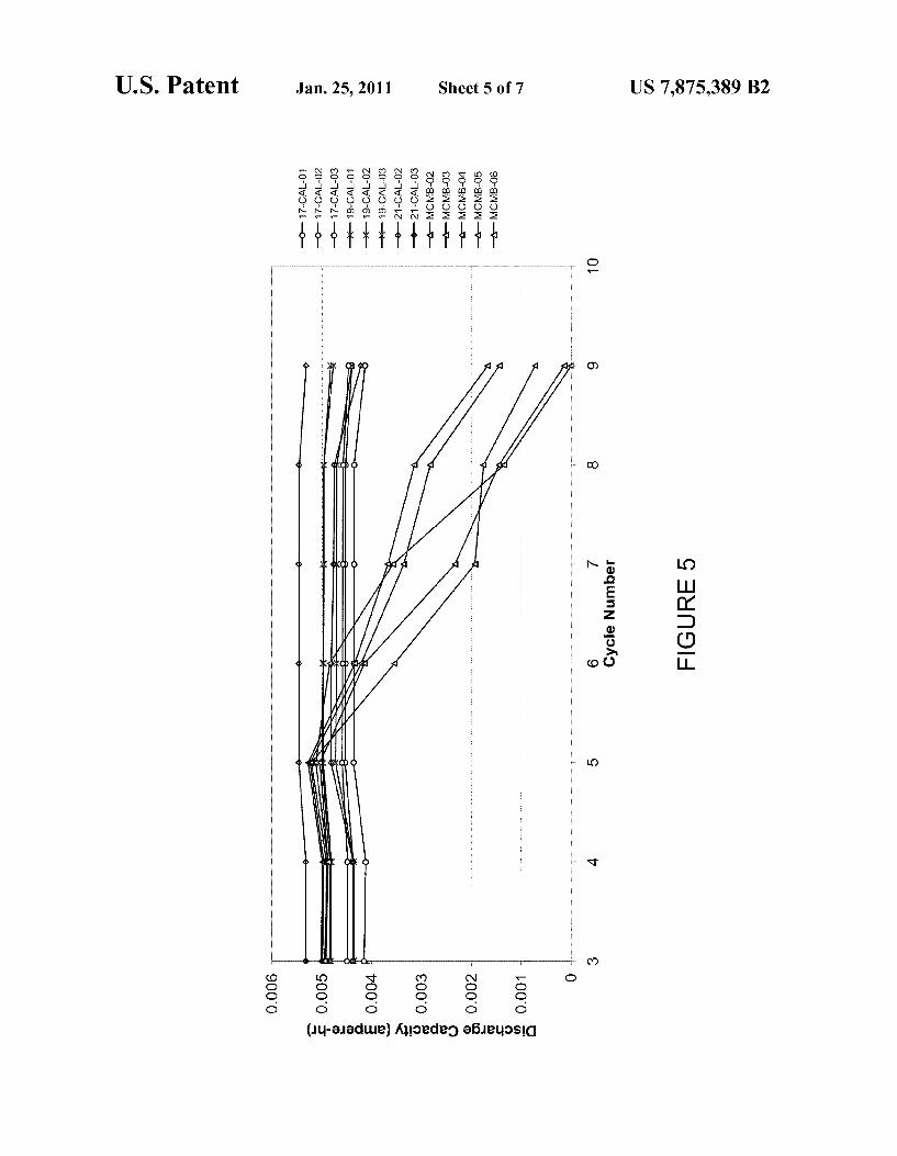
FIG. 5 is a graph illustrating the discharge capacity of battery cells and the effect of overdischarge cycling of such cells.
FIG. 6 is a graph illustrating Voltage traces for a cell using a Li TiO2 active material on an aluminum negative current collector.
FIG. 7 is a graph illustrating Voltage traces for a compara tive cell using a carbon active material on a copper negative current collector.
FIG. 8 is a schematic view of a system in the form of an implantable medical device implanted within a body or torso of a patient.
FIG. 9 is schematic view of another system in the form of an implantable medical device.
DETAILED DESCRIPTION OF THE EXEMPLARY EMBODIMENTS
With reference to FIG.3, a schematic cross-sectional view of a portion of a lithium-ion battery 200 is shown according to an exemplary embodiment. According to an exemplary embodiment, the battery 200 has a rating of between approxi mately 10 and 1000 milliampere hours (mAh). According to another exemplary embodiment, the battery has a rating of between approximately 100 and 400 mAh. According to another exemplary embodiment, the battery is an approxi mately 300 mAh battery. According to another exemplary embodiment, the battery is an approximately 75 mAh battery. The battery 200 includes at least one positive electrode 210
and at least one negative electrode 220. The electrodes may be provided as flat or planar components of the battery 200, may be wound in a spiral or other configuration, or may be pro vided in a folded configuration. For example, the electrodes may be wrapped around a relatively rectangular mandrel Such that they form an oval wound coil for insertion into a rela tively prismatic battery case. According to other exemplary embodiments, the battery may be provided as a button cell battery, a thin film solid state battery, or as another lithium-ion battery configuration. The battery case (not shown) may be made of a metal Such
as aluminum or an aluminum alloy or another metal. Accord ing to an exemplary embodiment, the battery case may be made of titanium, a titanium alloy, or stainless steel. Accord ing to another exemplary embodiment, the battery case may be made of a plastic material or a plastic-foil laminate mate rial (e.g., an aluminum foil provided intermediate a polyolefin layer and a polyester layer).
According to an exemplary embodiment, the negative elec trode is coupled to an aluminum case by a member or tab comprising aluminum oran aluminum alloy. An aluminum or aluminum alloy member or tab may be coupled or attached to the positive electrode. The tabs may serve as terminals for the battery according to an exemplary embodiment. The dimensions of the battery 200 may differ according to
a variety of exemplary embodiments. For example, according to one exemplary embodiment in which the electrodes are wound such that they may be provided in a relatively pris matic battery case, the battery has dimensions of between approximately 30-40 mm by between approximately 20-30 mm by between approximately 5-7 mm. According to another exemplary embodiment, the dimensions of the battery are approximately 20 mm by 20 mm by 3 mm. According to

US 7,875,389 B2 5
another exemplary embodiment, a battery may be provided in the form of a button cell type battery having a diameter of approximately 30 mm and a thickness of approximately 3 mm. It will be appreciated by those of skill in the art that such dimensions and configurations as are described herein are illustrative only, and that batteries in a wide variety of sizes, shapes, and configurations may be produced in accordance with the novel concepts described herein. An electrolyte 230 is provided intermediate or between the
positive and negative electrodes to provide a medium through which lithium ions may travel. The electrolyte may be a liquid (e.g., a lithium salt dissolved in one or more non-aqueous Solvents). According to an exemplary embodiment, the elec trolyte may be a mixture of polycarbonate (PC) and a 1.0 M salt of LiPF. According to another exemplary embodiment, an electrolyte may be used that is free of ethylene carbonate, vinylene carbonate or a lithium bis-Oxalatoborate Salt (some times referred to as LiBOB) that may be used in conventional lithium batteries.
Various other electrolytes may be used according to other exemplary embodiments. According to an exemplary embodiment, the electrolyte may be a lithium salt dissolved in a polymeric material Such as poly(ethylene oxide) or silicone. According to another exemplary embodiment, the electrolyte may be an ionic liquid such as N-methyl-N-alkylpyrroli dinium bis(trifluoromethanesulfonyl)imide Salts. According to another exemplary embodiment, the electrolyte may be a Solid state electrolyte Such as a lithium-ion conducting glass such as lithium phosphorous oxynitride (LiPON). According to another exemplary embodiment, the electrolyte may be a 1:1 mixture of ethylene carbonate to diethylene carbonate (EC:DEC) in a 1.0 M salt of LiPF. According to another exemplary embodiment, the electrolyte may include a polypropylene carbonate solvent and a lithium bis-Oxalatobo rate salt. According to other exemplary embodiments, the electrolyte may comprise one or more of a PVDF copolymer, a PVDF-polyimide material, and organosilicon polymer, a thermal polymerization gel, a radiation cured acrylate, a par ticulate with polymer gel, an inorganic gel polymer electro lyte, an inorganic gel-polymer electrolyte, a PVDF gel, poly ethylene oxide (PEO), a glass ceramic electrolyte, phosphate glasses, lithium conducting glasses, lithium conducting ceramics, and an inorganic ionic liquid gel, among others. A separator 250 is provided intermediate or between the
positive electrode 210 and the negative electrode 220. According to an exemplary embodiment, the separator 250 is a polymeric material Such as a polypropylene/polyethelene copolymer or another polyolefin multilayer laminate that includes micropores formed therein to allow electrolyte and lithium ions to flow from one side of the separator to the other. The thickness of the separator 250 is between approximately 10 micrometers (Lm) and 50 um according to an exemplary embodiment. According to a particular exemplary embodi ment, the thickness of the separator is approximately 25um and the average pore size of the separator is between approxi mately 0.02 um and 0.1 um. The positive electrode 210 includes a current collector 212
made of a conductive material Such as a metal. According to an exemplary embodiment, the current collector 212 com prises aluminum or an aluminum alloy.
According to an exemplary embodiment, the thickness of the current collector 212 is between approximately 5um and 75um. According to a particular exemplary embodiment, the thickness of the current collector 212 is approximately 20um. It should also be noted that while the positive current collector 212 has been illustrated and described as being a thin foil material, the positive current collector may have any of a
5
10
15
25
30
35
40
45
50
55
60
65
6 variety of other configurations according to various exem plary embodiments. For example, the positive current collec tor may be a grid Such as a mesh grid, an expanded metal grid, a photochemically etched grid, or the like. The current collector 212 has a layer of active material 216
provided thereon (e.g., coated on the current collector). While FIG.3 shows that the active material 216 is provided on only one side of the current collector 212, it should be understood that a layer of active material similar or identical to that shown as active material 216 may be provided or coated on both sides of the current collector 212.
According to an exemplary embodiment, the active mate rial 216 is a material or compound that includes lithium. The lithium included in the primary active material 216 may be doped and undoped during discharging and charging of the battery, respectively. According to an exemplary embodi ment, the primary active material 216 is lithium cobalt oxide (LiCoO). According to another exemplary embodiment, the active material provided on the current collector 212 is LiMn2O4. According to another exemplary embodiment, the active material provided on the current collector 212 is a material of the form LiCo, Ni-O, where x is between approximately 0.05 and 0.8. According to another exemplary embodiment, the active material provided on the current col lector 212 is a material of the form LiNiCo, MnO, (e.g., LiNiCoaMn2O2). According to another exem plary embodiment, the active material provided on the current collector 212 is a metal-doped variety of one of these mate rials, such as a material of the form LiM,Co.Ni--O. where M is aluminum or titanium and X is between approxi mately 0.05 and 0.3 and y is between approximately 0.1 and O3.
For certain applications, it may be desirable to provide a battery having a cell Voltage of greater than approximately 3 Volts. In such cases, a higher-Voltage active material may be utilized on the positive current collector, Such as a material in the form Li-Co, Fe,Mn4-g-Os (e.g., LiCooFeo, MnOs). It is believed that such an active material may charge up to 5.2 Volts versus a lithium reference electrode, making it possible to obtain an overall cell Voltage of up to approximately 3.7 volts. Other relatively high-volt age active materials that may be used for the positive elec trode include LiCoPO: LiCoPOF; LiNiPO; LiNio.2Lio2MnoglC2. and LiCo,Mn2O (e.g., LiCuo, Mn,O4).
According to various other exemplary embodiments, the active material may include a material Such as a material of the form Li MO, where M is a metal (e.g., LiCoO, LiNiO, and LiMnO.), a material of the form Li(M', M") O where M and M" are different metals (e.g., Li(Cr, Mn.) O. Li (AllMn)O, Li (CoM)O where M is a metal, LiCo,Ni)O, and Li (CoFe)O)), a material of the form L-(Mn, Ni, CO.).O. (e.g., Li(Mn/NiaCos)O. LiCMn/Ni Co-Mg)O, Li(Mino-Nio-CO)O, and LiCMno. Nio Coos)O), a material of the form Li(Mn NiCo).O., a material of the form Li(Mn, Ni, Co-Al...) O., a material of the form Li(NiCo,Al)O, (e.g., LiONiosCoos Aloos)O2), a material of the form Li(Ni CoM)O, where M is a metal, a material of the form Li (Ni, Mn, M)O, where M is a metal, a material of the form Li(Ni, Mn, Cr)O, LiMnO, a material of the form LiM"M"O where M' and M" are different metals (e.g., LiMn., Ni, O. Li O, LiMns Nios.O., LiNiCuO, LiMn-AlO4, LiNiosTios C4, and Lios Aloi MinissO4. F.), Li2MnO, a material of the form Li, V.O. (e.g., LiVOs, LiVOs, and LiVO), a material of the form LiMPO where Mis a metal or LiM"M"PO, where M' and M" are different

US 7,875,389 B2 7
metals (e.g., LiFePO, LiFe,MPO where M is a metal, LiVOPO and LiV(PO), and LiMPO, where M is a metal Such as iron or vanadium and X is a halogen Such as fluorine, and combinations thereof. A binder material may also be utilized in conjunction with
the layer of active material 216 to bond or hold the various electrode components together. For example, according to an exemplary embodiment, the layer of active material may include a conductive additive such as carbon black and a binder such as polyvinylidine fluoride (PVDF) or an elasto meric polymer.
According to an exemplary embodiment, the thickness of the layer of active material 216 is between approximately 0.1 um and 3 mm. According to another exemplary embodiment, the thickness of the layer of active material 216 is between approximately 25um and 300 Lum. According to a particular exemplary embodiment, the thickness of the layer of active material 216 is approximately 75um. The negative electrode 220 includes a current collector 222
that is made of a conductive material Such as a metal. Accord ing to an exemplary embodiment, the current collector 222 is aluminum oran aluminum alloy. One advantageous feature of utilizing an aluminum or aluminum alloy current collector is that Such a material is relatively inexpensive and may be relatively easily formed into a current collector. Other advan tageous features of utilizing an aluminum or aluminum cur rent collector is that such a material may exhibit a relatively low density, a relatively high conductivity, is relatively readily weldable, and is generally commercially available. According to another exemplary embodiment, the current collector 222 is titanium or a titanium alloy. According to another exemplary embodiment, the current collector 222 is silver or a silver alloy.
While the negative current collector 222 has been illus trated and described as being a thin foil material, the negative current collector may have any of a variety of other configu rations according to various exemplary embodiments. For example, the negative current collector may be a grid Such as a mesh grid, an expanded metal grid, a photochemically etched grid, or the like.
According to an exemplary embodiment, the thickness of the current collector 222 is between approximately 100 nm and 100 um. According to another exemplary embodiment, the thickness of the current collector 222 is between approxi mately 5 um and 25um. According to a particular exemplary embodiment, the thickness of the current collector 222 is approximately 10 Jum. The negative current collector 222 has an active material
224 provided thereon. While FIG. 3 shows that the active material 224 is provided on only one side of the current collector 222, it should be understood that a layer of active material similar or identical to that shown may be provided or coated on both sides of the current collector 222.
According to an exemplary embodiment, the negative active material 224 is a lithium titanate material Such as Li TiO2 (sometimes referred to as Li Li TissO4, with Osx<1). Other lithium titanate materials which may be suit able for use as the negative active material may include one or more of the following lithium titanate spinel materials: H, Li, TiO,O4, H, Li, TiO,O4, Li M., Tis-O2, Li, TiO4. Li, TiO, Lia Tig, Lioss-MIO4. Li-TiO, Li-Ti47s Vo25O12, Lia Ti47s Feo.25O1 iss, Li Ti 4s Minoso2. and LiM"M"XO (where M' is a metal such as nickel, cobalt, iron, manganese, Vanadium, copper, chromium, molybde num, niobium, or combinations thereof M" is an optional three Valent non-transition metal, and X is Zirconium, tita nium, or a combination of these two). Note that such lithium
5
10
15
25
30
35
40
45
50
55
60
65
8 titanate spinel materials may be used in any state of lithiation (e.g., Li TiO2, where 0sXs3). A binder material may also be utilized in conjunction with
the layer of active material 224. For example, according to an exemplary embodiment, the layer of active material may include a binder such as polyvinylidine fluoride (PVDF) or an elastomeric polymer. The active material 224 may also include a conductive material Such as carbon (e.g., carbon black) at weight loadings of between Zero and ten percent to provide increased electronic conductivity.
According to various exemplary embodiments, the thick ness of the active material 224 is between approximately 0.1 um and 3 mm. According to other exemplary embodiments, the thickness of the active material 224 may be between approximately 25 um and 300 um. According to another exemplary embodiment, the thickness of the active material 224 may be between approximately 20 Lum and 90 um, and according to a particular exemplary embodiment, approxi mately 75 um.
FIG. 4 is a graph 300 illustrating the theoretical charging and discharging behavior for a lithium-ion battery con structed in accordance with an exemplary embodiment Such as that shown and described with regard to FIG. 3. Curve 310 represents the electrode potential versus a lithium reference electrode for a positive electrode (e.g., positive electrode 210) that includes an aluminum current collector having a LiCoO. primary active material provided thereon.
Curve 320 represents the electrode potential versus a lithium reference electrode for a negative electrode that includes an aluminum current collector having a lithium titanate active material provided thereon. The difference between curves 310 and 320 is representative of the overall cell voltage of the battery, and is represented as curve 340 in FIG. 4. As shown in FIG.4, the relatively flat portion (labeled with
reference numeral 324) of the curve 320 representing the Voltage of the negative electrode (e.g., electrode 220) is at a level of between approximately 1.5 and 1.6 volts. Thus, the relatively flat portion 324 of the curve 320 is at a level that is significantly greater than that of an electrode utilizing a car bon active material (see, e.g., curve 120 in FIG. 2, which represents the theoretical voltage versus a lithium reference electrode for a negative electrode incorporating a carbon active material). When the cell is charged, the potentials of the positive and
negative electrodes progress to the right along curves 310 and 320, respectively. When the cell is discharged, the potentials of the positive and negative electrode potentials progress toward the left along curves 310 and 320, respectively, with a Zero Voltage crossing potential of approximately 3.8 volts (shown as point 330 in FIG. 4). As the cell approaches a zero Voltage condition (e.g., curve 340 drops to Zero Volts, repre senting the Voltage differential between the positive and nega tive electrodes), the voltage of the positive electrode is above the decomposition potential of the LiCoO active material provided thereon, which is shown as dashed line 322 in FIG. 4. Additionally, because an aluminum current collector is utilized for the negative electrode, the negative electrode has increased resistance to corrosion as compared to copper materials which may be utilized for the negative electrode.
It is intended that a lithium-ion battery such as that described herein may be fully discharged while the materials for both electrodes, including their corresponding current collectors, are stable (e.g., corrosion of the current collectors and/or the decomposition of active material may be avoided, etc.). For example, it is intended that a battery produced using a positive electrode including an aluminum current collector

US 7,875,389 B2
and a LiCoO active material and a negative electrode includ ing an aluminum current collector and a lithium titanate active material will allow for repeated cycling of the battery to Zero or near-Zero Voltage conditions without a significant decline in battery charging capacity or battery performance. One potential advantageous feature of such an arrangement is that the occurrence of reduced device functionality (i.e., the need to recharge more frequently) and corrosion of the cur rent collectors and battery case (with the incumbent possibil ity of leaking potentially corrosive and toxic battery contents) may be reduced or avoided.
Various advantageous features may be obtained by batter ies such as those shown and described herein. For example, use of batteries which utilize a lithium titanate active material on an aluminum electrode may eliminate the need to utilize circuitry to disconnect batteries approaching near-Zero Volt age conditions, since Such batteries may be cycled to Zero Voltage and near-Zero Voltage repeatedly without a significant loss in battery performance or capacity. By not utilizing cir cuitry for this function, Volume and cost reductions may be obtained. One advantageous feature of using a lithium titanate mate
rial is that it is believed that when used in a negative electrode of a lithium-ion battery, such materials will cycle lithium at a potential plateau of about 1.55 volts versus a lithium refer ence electrode. This is Substantially higher than graphitic carbon, which cycles lithium at approximately 0.1 volts in the fully charged state (see, e.g., FIG. 2, in which curve 120 is representative of the charging/discharging behavior of a negative electrode utilizing graphitic carbon). As a result, the battery using lithium titanate is believed to be less likely to result in plating of lithium (which occurs at 0 volts versus a lithium reference) while being charged. Lithium plating is a well-known phenomenon that can lead to loss in performance of lithium ion batteries.
Another advantage of using a lithium titanate material instead of a carbonaceous material for the negative active material is that it is believed that the use of a lithium titanate material allows for charging and discharging of the battery at higher rates than is capable using carbonaceous materials. For example, a common upper limit for the rate of charge in lithium ion batteries is about 1 C (meaning that the battery can be fully charged from the discharged State in one hour). Con versely, it has been reported in literature that lithium titanate may be charged at rates up to 10 C (i.e., attaining full charge in /10 hour, or six minutes). One potential reason for this is that negative electrodes utilizing a lithium titanate active material are believed to be less susceptible to the risk of lithium plating. The ability to recharge a battery more quickly may substantially increase the functionality of devices that employ such a battery.
It is also believed that the use of negative electrodes that include a lithium titanate active material may allow for charg ing of the battery at Voltages that exceed those used in the charging of batteries in which the negative electrodes utilize carbon active materials. One potential advantage of Such a property is that nonhermetic cells (e.g., cells using a rivet polymer feedthrough, foil package, etc.) may be produced. Nonhermetic cells typically have greater energy density than other cells, are relatively inexpensive to manufacture, and may be produced using a wider variety of materials (e.g., polymer foil laminates, etc.). In medical applications in par ticular, such cells have conventionally utilized with polymer or gel electrolytes which have lower vapor pressure to provide a reduced risk of leakage. However, Such electrolytes are typically less conductive than liquid electrolytes, resulting in relatively low power and/or charge rate. By utilizing a battery
10
15
25
30
35
40
45
50
55
60
65
10 that includes a lithium titanate active material on an alumi num current collector, the charge Voltage of the cell may be increased to compensate for resistive losses (e.g., IR drops) in the electrolyte.
Lithium titanate materials are also believed to offer supe rior cycle life because they are so called “Zero-strain mate rials. Zero strain materials have crystal lattices which do not experience shrinkage or contraction with lithium doping/de doping, making them free from Strain-related degradation mechanisms. Such materials also have a relatively high spe cific capacity (approximately 155 mAh/g) and a similar volu metric capacity density to graphitic carbon. A further advantage of the higher potential of the lithium
titanate material is that it avoids decomposition of organic Solvents (such as propylene carbonate) commonly used in lithium ion batteries. In so doing, it may reduce negative consequences such as formation of gas, cell Swelling, and reduction of reversible battery capacity.
Another potential advantageous feature of utilizing a lithium titanate material for the negative electrode active material is that more favorable design rules may be possible. For example, in conventional lithium-ion cells, the negative electrode must overlap the positive electrode by approxi mately 1 mm on all edges in order to avoid plating of lithium. For applications in which space is a concern, this may result in significant wasted Volume (e.g., for a cranial implant cell that is approximately 22 mm high, this may result in wasted Volume of approximately 10 percent). Because use of a titan ate material reduces the risk of lithium plating, it is believed that the design requirement of overlapping positive and nega tive electrodes may be unnecessary, thus allowing the pro duction of lithium-ion batteries with improved energy den sity. The lithium diffusion coefficient for lithium titanate mate
rials may be on the order of approximately 2x10 cm/s, which is approximately ten times that of carbon, thus allow ing a comparatively rapid Sustained rate capability. The use of Such materials may allow the manufacture of batteries having lower Surface area electrodes while still achieving adequate power and recharge rates. According to an exemplary embodiment, a battery utilizes monolithic (i.e., single-plate) electrodes in a coin cellor a foil laminate package. Due to the comparatively rapid Sustained rate capability of the lithium titanate material, the battery may be relatively thin (e.g., approximately 1 mm) and inexpensive. Further, according to other exemplary embodiments, batteries may be produced in contoured shapes, which may allow for packaging of Such batteries unobtrusively and in unconventional ways in a device (such as along an inner Surface of a device housing or case, such as the housing or case of a medical device Such as a pacemaker). This may be especially advantageous in a device such as a cranial implant, where it may be desirable to provide the device having a contour to match the curvature of the skull.
Conventional lithium-ion cells are balanced with a nominal excess negative active material of between approximately five and ten percent to avoid plating of lithium. The use of excess active material results in a larger battery, which results in a cell having reduced energy density. According to an exemplary embodiment, a battery or cell using a lithium titanate active material on an aluminum negative current col

US 7,875,389 B2 11
lector may be produced without excess negative active mate rial (e.g., as a “balanced design).
Comparative Example #1
This example illustrates the overdischarge performance of lithium ion batteries utilizing a negative electrode having Li TiO2 active material coated onto an aluminum current collector as compared to the performance of lithium ion bat teries in which a carbon active material (graphitized MCMB) is coated onto a copper current collector. In all cases, the electrodes were cycled against positive electrodes having a LiCoO active material with a capacity of 5.53 mAh coated on an aluminum current collector.
Negative electrodes were produced by mixing lithium titanate (commercially available from Sid Chemie Corpora tion) with a poly(vinylidine fluoride) binder, carbon black and 1-methyl-2-pyrolidone (NMP) into a slurry and depositing the mixture onto an aluminum foil current collector and dry ing on a heated drum. The active weight percent of the dried coating was 89.25%. Three coating deposition levels of the coating were used: 17.37, 18.78 and 20.69 mg/cm. Based on the theoretical specific capacity of Li TiO2 (155 mAh/g), the capacity of these electrodes was 4.76, 5.14 and 5.67 mAh, respectively. Thus, when cycled against the positive elec trodes, the cell balance (i.e., the ratio of the negative and positive electrode capacities) was 0.85, 0.93 and 1.02, respec tively.
After drying, the electrode coatings were calendared to a density of about 2.2 g/cm and cut into circular disks having an area of 1.98 cm. Lithium ion cells were produced by assembling these electrodes into type-2032 coin cell hard ware. A microporous polyolefin separator was used to sepa rate the negative and positive electrodes, and the cells were activated by the addition of electrolyte consisting of 1 M LiPF in a mixture of propylene carbonate, ethylene carbon ate and diethyl carbonate.
Comparative cells were manufactured in identical fashion, with the exception of the fact that the negative electrodes utilized graphite active material (mesocarbon microbeads) coated on copper foil.
Group/Serial
5
10
15
25
30
35
Number
17-CAL-01 17-CAL-02 17-CAL-03
19-CAL-01 19-CAL-02 19-CAL-03
21-CAL-02 21-CAL-03
MCMB-02 MCMB-03 MCMB-04 MCMB-OS MCMB-06
12 Cells were charged and discharged at a rate of 0.2 mA using
an ARBIN BT2000 battery cycler. For the first four cycles, the cells were cycled over a normal operating Voltage range (3.0 to 1.8 V for the Li TiO, cells, 4.075 to 2.75 volts for the comparative cells). After completing four cycles, the cells then underwent four overdischarge cycles, where they were discharged to 0 Volts and charged back to their normal charge Voltage. The overdischarge took place as a sequence of steps at progressively lower currents: 0.2 mA down to 1.8 volts, 0.05 mA to 1.0 volts and 0.01 mA to 0 volts. Following the overdischarge cycles, the cells were then cycled over the original Voltage range to measure the recovered capacity for the cells.
A graph showing the discharge capacity versus cycle num ber for each of the cells tested is shown in FIG. 5. Test data revealed a loss of discharge capacity over time after repeated overdischarge cycling for the comparative cells (i.e., cells using carbon active material on copper current collectors), while little or no loss of discharge capacity was observed for cells utilizing Li TisC) negative active material and an alu minum foil current collector.
TABLE 1 lists the cell discharge capacity of the cells dur ing the fourth and ninth cycles of testing (i.e., the cycles immediately preceding and immediately following the over discharge cycles). For cells using negative electrodes with a Li TiO2 active material on an aluminum current collector, there is little or no loss in capacity following the overdis charge cycles. For the comparative cells (graphite active material on copper current collector), the average capacity loss was observed to be 84%.
TABLE 1 also lists the ratio of theoretical capacity of the negative and positive electrodes for the Li TiO2 cells. This data indicates that little or no capacity loss may be obtained regardless of whether the cells are negative limited (ratio of negative to positive electrode capacity less than 1) or positive limited (ratio of negative to positive electrode capacity greater than 1).
TABLE 1.
Negative/Positive Cycle 4 Cycle 9 Negative Electrode Capacity Discharge Discharge Capacity LOSS Active Ratio for Capacity Capacity Due to Material LiTiO2 Cells (mAh) (mAh) Overdischarge
LiTis012 O.86 4.12 4.13 -O.3% Li Ti5012 O.86 4.37 4.40 -0.6% Li Ti5012 O.86 4.49 4.47 O.4%
Average 4.33 4.33 -0.2% Standard Dev. O.19 O.18 O.S90
Li Ti5012 O.93 4.81 4.83 -0.4% Li Ti5012 O.93 4.36 4.40 -O.8% Li Ti5012 O.93 4.84 4.78 1.2%
Average 4.67 4.67 O.0% Standard Dev. 0.27 O.24 1.1%
Li Ti5012 1.02 5.32 5.32 O.1% LiTis012 1.02 4.37 4.23 3.2%
Average 4.84 4.77 1.6% Standard Dev. 0.67 O.77 2.2%
Carbon na 4.99 1.68 66.4% Carbon na 4.96 1.44 71.0% Carbon na 4.88 O.14 97.1% Carbon na 4.91 0.72 85.3% Carbon na 4.88 O.OO 100.0%
Average 4.93 O.80 84.0% Standard Dev. O.OS 0.75 15.1%

US 7,875,389 B2 13
Comparative Example #2
This example illustrates potential advantageous features of utilizing a Li TisC) active material on a negative current collector made of aluminum as opposed to a negative current collector made of copper. In all cases described below, the negative electrodes were cycled against positive electrodes having a LiCoO active material having a capacity of 14.1 mAh. A negative electrode was produced by mixing lithium
titanate (commercially available from Sid Chemie Corpora tion) with poly(vinylidine flouride) binder, carbon black and 1-methyl-2-pyrolidone (NMP) into a slurry and depositing the slurry onto an aluminum foil current collector and drying on a heated drum. The active weight percent of the dried coating was 89.25%. The coating deposition level was 18.78 mg/cm. The active area of the electrode was 5.04 cm. Based on the theoretical specific capacity of Li TisC) (155 mAh/ g), the capacity of this electrode was 13.1 mAh. A battery was assembled by combining the above-men
tioned negative and positive electrodes, spaced by a microporous separator, inside of a hermetic stainless Steel can. The negative electrode was welded onto the inside of the can, and the positive electrode was connected to a an electri cal feedthrough. A lithium reference electrode was placed on the end of a second feedthrough pin, such that the lithium was located in the headspace of the cell. A polyolefin spacer was placed inside the can, parallel to the positive electrodes, to maintain uniform contact across the entire electrode surface. The cell was activated by filling with electrolyte consisting of 1 M LiPF in a mixture of propylene carbonate, ethylene carbonate and diethyl carbonate. The battery was cycled by charging and discharging at a
current of 0.5 mA using an ARBIN BT2000 battery cycler. For the first four cycles, the cell was cycled over a typical operational Voltage range (charge to 3.0 Volts, discharge to 1.8 volts). Next, the cell was subjected to four overdischarge steps consisting of a normal charge followed by overdis charge to 0 Volts. The overdischarge took place as a sequence of galvanostatic steps, as follows: 0.5 mA down to 1.8 volts, 0.125 mA down to 1.0 volts, 0.05 mA down to 0 volts. After the overdischarge steps, the cell was again charged and dis charged per the original method. An auxiliary Voltage mea Suring channel was used to record the potential of the negative electrode versus the lithium reference electrode. The poten tial of the positive electrode was obtained by summing the total battery voltage with the auxiliary voltage.
FIG. 6 shows three voltage traces for the cell. Curve 630 is the total cell voltage, curve 620 is the positive electrode (versus Li reference) and curve 610 is the negative electrode (versus Li reference). During normal cycling, the potential of the negative electrode ranges between about 1.2 and 2.1 Volts. However, during overdischarge, the potential of the negative electrode increases until it meets the potential of the positive electrode. The two electrodes meet at a potential of approxi mately 3.9 volts. At this point, known as the “Zero-volt cross ing potential.” the cell voltage (defined as the difference between the positive and negative electrode potentials) is 0 Volts. If this cell were to have been made using a copper current collector for the negative electrodes, it is expected that the copper would have corroded, because 3.9 volts is several hundred millivolts more anodic than the corrosion potential of copper (approximately 3.5 volts). A battery was fabricated and tested using methods identi
cal to those described above. The battery utilized a negative electrode including a graphitized carbon active material on a copper current collector. FIG. 7 shows the voltage traces for
5
10
15
25
30
35
40
45
50
55
60
65
14 this battery (i.e., curve 710 is the total cell voltage, curve 720 is the positive electrode (versus Li reference) and curve 730 is the negative electrode (versus Li reference)). During the over discharge cycle, the potential of the negative electrode was never above approximately 3.5 volts. It is believed that the reason for this is that at this point, the copper current collector was freely corroding, with the driving force for the corrosion reaction being Supplied by the positive electrode.
According to an exemplary embodiment, lithium-ion bat teries such as those described above may be used in conjunc tion with medical devices such as medical devices that may be implanted in the human body (referred to as “implantable medical devices” or “IMD's').
FIG. 8 illustrates a schematic view of a system 400 (e.g., an implantable medical device) implanted within a body or torso 432 of a patient 430. The system 400 includes a device 410 in the form of an implantable medical device that for purposes of illustration is shown as a defibrillator configured to provide a therapeutic high voltage (e.g., 700 volt) treatment for the patient 430. The device 410 includes a container or housing 414 that is
hermetically sealed and biologically inert according to an exemplary embodiment. The container may be made of a conductive material. One or more leads 416 electrically con nect the device 410 and to the patient’s heart 420 via a vein 422. Electrodes 417 are provided to sense cardiac activity and/or provide an electrical potential to the heart 420. At least a portion of the leads 416 (e.g., an end portion of the leads shown as exposed electrodes 417) may be provided adjacent or in contact with one or more of a Ventricle and an atrium of the heart 420. The device 410 includes a battery 440 provided therein to
provide powerfor the device 410. According to another exem plary embodiment, the battery 440 may be provided external to the device or external to the patient 430 (e.g., to allow for removal and replacement and/or charging of the battery). The size and capacity of the battery 440 may be chosen based on a number of factors, including the amount of charge required for a given patient’s physical or medical characteristics, the size or configuration of the device, and any of a variety of other factors. According to an exemplary embodiment, the battery is a 5 mAh battery. According to another exemplary embodiment, the battery is a 300 mAh battery. According to various other exemplary embodiments, the battery may have a capacity of between approximately 10 and 1000 mAh.
According to other exemplary embodiments, more than one battery may be provided to power the device 410. In such exemplary embodiments, the batteries may have the same capacity or one or more of the batteries may have a higher or lower capacity than the other battery or batteries. For example, according to an exemplary embodiment, one of the batteries may have a capacity of approximately 500 mAh while another of the batteries may have a capacity of approxi mately 75 mAh.
According to another exemplary embodiment shown in FIG. 9, an implantable neurological stimulation device 500 (an implantable neuro stimulator or INS) may include a bat tery 502 such as those described above with respect to the various exemplary embodiments. Examples of Some neuro stimulation products and related components are shown and described in a brochure titled “Implantable Neurostimulation Systems’ available from Medtronic, Inc. An INS generates one or more electrical stimulation sig
nals that are used to influence the human nervous system or organs. Electrical contacts carried on the distal end of a lead are placed at the desired stimulation site Such as the spine or brain and the proximal end of the lead is connected to the INS.

US 7,875,389 B2 15
The INS is then surgically implanted into an individual such as into a subcutaneous pocket in the abdomen, pectoral region, or upper buttocks area. A clinician programs the INS with a therapy using a programmer. The therapy configures parameters of the stimulation signal for the specific patients therapy. An INS can be used to treat conditions such as pain, incontinence, movement disorders such as epilepsy and Par kinson's disease, and sleep apnea. Additional therapies appear promising to treat a variety of physiological, psycho logical, and emotional conditions. Before an INS is implanted to deliver a therapy, an external screener that replicates some or all of the INS functions is typically connected to the patient to evaluate the efficacy of the proposed therapy.
The INS 500 includes a lead extension 522 and a stimula tion lead 524. The stimulation lead 524 is one or more insu lated electrical conductors with a connector 532 on the proxi mal end and electrical contacts (not shown) on the distal end. Some stimulation leads are designed to be inserted into a patient percutaneously, such as the Model 3487A Pisces QuadR) lead available from Medtronic, Inc. of Minneapolis Minn., and stimulation some leads are designed to be Surgi cally implanted, such as the Model 3998 Specify(R) lead also available from Medtronic.
Although the lead connector 532 can be connected directly to the INS 500 (e.g., at a point 536), typically the lead con nector 532 is connected to a lead extension 522. The lead extension 522, such as a Model 7495 available from Medtronic, is then connected to the INS 500.
Implantation of an INS 520 typically begins with implan tation of at least one stimulation lead 524, usually while the patient is under a local anesthetic. The stimulation lead 524 can either be percutaneously or surgically implanted. Once the stimulation lead 524 has been implanted and positioned, the stimulation leads 524 distal end is typically anchored into position to minimize movement of the stimulation lead 524 after implantation. The stimulation leads 524 proximal end can be configured to connect to a lead extension 522. The INS500 is programmed with a therapy and the therapy
is often modified to optimize the therapy for the patient (i.e., the INS may be programmed with a plurality of programs or therapies such that an appropriate therapy may be adminis tered in a given situation). In the event that the battery 502 requires recharging, an external lead (not shown) may be used to electrically couple the battery to a charging device or apparatus. A physician programmer and a patient programmer (not
shown) may also be provided to allow a physician or a patient to control the administration of various therapies. A physician programmer, also known as a console programmer, uses telemetry to communicate with the implanted INS 500, so a clinician can program and manage a patients therapy stored in the INS 500, troubleshoot the patient’s INS 500 system, and/or collect data. An example of a physician programmer is a Model 7432 Console Programmer available from Medtronic. A patient programmer also uses telemetry to com municate with the INS 500, so the patient can manage some aspects of her therapy as defined by the clinician. An example of a patient programmer is a Model 7434 Itrel(R) 3 EZ Patient Programmer available from Medtronic.
While the medical devices described herein (e.g., systems 400 and 500) are shown and described as a defibrillator and a neurological stimulation device, it should be appreciated that other types of implantable medical devices may be utilized according to other exemplary embodiments, such as pace makers, cardioverters, cardiac contractility modules, drug administering devices, diagnostic recorders, cochlear implants, and the like for alleviating the adverse effects of
10
15
25
30
35
40
45
50
55
60
65
16 various health ailments. According to still other embodi ments, non-implantable medical devices or other types of devices may utilize batteries as are shown and described in this disclosure.
It is also contemplated that the medical devices described herein may be charged or recharged when the medical device is implanted within a patient. That is, according to an exem plary embodiment, there is no need to disconnect or remove the medical device from the patient in order to charge or recharge the medical device. For example, transcutaneous energy transfer (TET) may be used, in which magnetic induc tion is used to deliver energy from outside the body to the implanted battery, without the need to make direct physical contact to the implanted battery, and without the need for any portion of the implant to protrude from the patient’s skin. According to another exemplary embodiment, a connector may be provided external to the patient’s body that may be electrically coupled to a charging device in order to charge or recharge the battery. According to other exemplary embodi ments, medical devices may be provided that may require removal or detachment from the patient in order to charge or recharge the battery.
It is important to note that the construction and arrange ment of the lithium-ion battery as shown and described with respect to the various exemplary embodiments is illustrative only. Although only a few embodiments of the present inven tions have been described in detail in this disclosure, those skilled in the art who review this disclosure will readily appre ciate that many modifications are possible (e.g., variations in sizes, dimensions, structures, shapes and proportions of the various elements, values of parameters, mounting arrange ments, use of materials, colors, orientations, etc.) without materially departing from the novel teachings and advantages of the Subject matter recited in the claims. Accordingly, all such modifications are intended to be included within the Scope of the present invention as defined in the appended claims. Other Substitutions, modifications, changes and omis sions may be made in the design, operating conditions and arrangement of the preferred and other exemplary embodi ments without departing from the scope of the present inven tion as expressed in the appended claims. What is claimed is: 1. A lithium-ion battery comprising: a positive electrode comprising a LiCoO active material; a polymeric separator configured to allow electrolyte and
lithium ions to flow between a first side of the separator and an opposite second side of the separator;
a liquid electrolyte comprising a lithium salt dissolved in at least one non-aqueous solvent;
a negative electrode comprising a lithium titanate active material;
wherein the positive electrode has a first capacity and the negative electrode has a second capacity that is less than the first capacity.
2. The lithium-ion battery of claim 1, wherein the lithium titanate material comprises Li TisC).
3. The lithium-ion battery of claim 1, wherein the ratio of the second capacity to the first capacity is 0.85.
4. The lithium-ion battery of claim 1, wherein the ratio of the second capacity to the first capacity is 0.93.
5. The lithium-ion battery of claim 1, wherein edges of the negative electrode do not extend beyond adjacent edges of the positive electrode.
6. The lithium-ion battery of claim 1, wherein the positive electrode and the negative electrode each include foil current collectors.

US 7,875,389 B2 17
7. The lithium-ion battery of claim 6, wherein the foil current collector of at least one of the positive electrode and the negative electrode comprises aluminum.
8. The lithium-ion battery of claim 1, wherein the LiCoO. active material of the positive electrode further comprises a binder and a conductive additive.
9. The lithium-ion battery of claim 1, wherein the battery has a nonhermetic construction.
10. The lithium-ion battery of claim 1, further comprising a battery housing that comprises aluminum.
11. The lithium-ion battery of claim 1, wherein the positive electrode and the negative electrode have a Zero Voltage cross ing potential above the decomposition potential of the active material of the positive electrode.
12. The lithium-ion battery of claim 1, wherein the sepa rator comprises a polyolefin material.
13. A lithium-ion battery comprising: a positive electrode having a first capacity and comprising
a foil current collector and a LiCoO active material; a polymeric separator; a liquid electrolyte; and a negative electrode having a second capacity that is not
greater than the first capacity, the negative electrode comprising a foil current collector and a lithium titanate active material.
14. The lithium-ion battery of claim 13, wherein the lithium titanate active material comprises Li TisC).
15. The lithium-ion battery of claim 13, wherein the second capacity is less than the first capacity.
16. The lithium-ion battery of claim 13, wherein the ratio of the second capacity to the first capacity is 0.85.
17. The lithium-ion battery of claim 13, whereintheratio of the second capacity to the first capacity is 0.93.
18. The lithium-ion battery of claim 13, wherein at least one edge of the negative electrode does not extend beyond an adjacent edge of the positive electrode.
19. The lithium-ion battery of claim 13, further comprising a porous polymeric separator provided between the positive electrode and the negative electrode.
20. The lithium-ion battery of claim 13, wherein the liquid electrolyte comprises a lithium salt dissolved in at least one non-aqueous solvent.
21. The lithium-ion battery of claim 20, wherein the elec trolyte comprises LiPF and at least non-aqueous solvent selected from the group consisting of propylene carbonate, ethylene carbone, and diethylene carbonate.
22. The lithium-ion battery of claim 13, wherein the current collector of the negative electrode comprises aluminum.
23. The lithium-ion battery of claim 13, wherein the current collector of the negative electrode comprises at least one material selected from the group consisting of silver and titanium.
10
15
25
30
35
40
45
50
18 24. The lithium-ion battery of claim 23, wherein the posi
tive current collector comprises aluminum. 25. The lithium-ion battery of claim 13, wherein the battery
is nonhermetic. 26. The lithium-ion battery of claim 13, further comprising
a battery case in contact with the negative electrode, the battery case comprising aluminum.
27. The lithium-ion battery of claim 13, wherein the active material of the negative electrode further comprises carbon and a poly(vinylidine fluoride) binder.
28. A lithium-ion battery comprising: a positive electrode having a first capacity and comprising
a foil current collector and an active material comprising LiCoO, a binder, and a conductive additive;
a liquid electrolyte; a negative electrode having a second capacity that is not
greater than the first capacity, the negative electrode comprising a foil current collector and a Li TisC) active material; and
a porous polymeric separator provided between the posi tive electrode and the negative electrode.
29. The lithium-ion battery of claim 28, wherein the ratio of the second capacity to the first capacity is 0.85.
30. The lithium-ion battery of claim 28, wherein the ratio of the second capacity to the first capacity is 0.93.
31. The lithium-ion battery of claim 28, wherein at least one edge of the negative electrode does not extend beyond an adjacent edge of the positive electrode.
32. The lithium-ion battery of claim 28, wherein the elec trolyte comprises LiPF and at least one material selected from the group consisting of propylene carbonate, ethylene carbone, and diethylene carbonate.
33. The lithium-ion battery of claim 28, wherein the nega tive electrode comprises an aluminum current collector.
34. The lithium-ion battery of claim 28, wherein the battery is nonhermetic.
35. The lithium-ion battery of claim 28, wherein the posi tive electrode and the negative electrode have Zero voltage below a corrosion potential of the aluminum current collector of the negative electrode.
36. The lithium-ion battery of claim 28, further comprising a polymeric separator provided intermediate the positive electrode and the negative electrode.
37. The lithium-ion battery of claim 28, further comprising a battery housing in contact with the negative electrode, the battery housing comprising aluminum.
38. The lithium-ion battery of claim 28, wherein the sepa rator is configured to allow the electrolyte and lithium ions to flow through the separator.
k k k k k
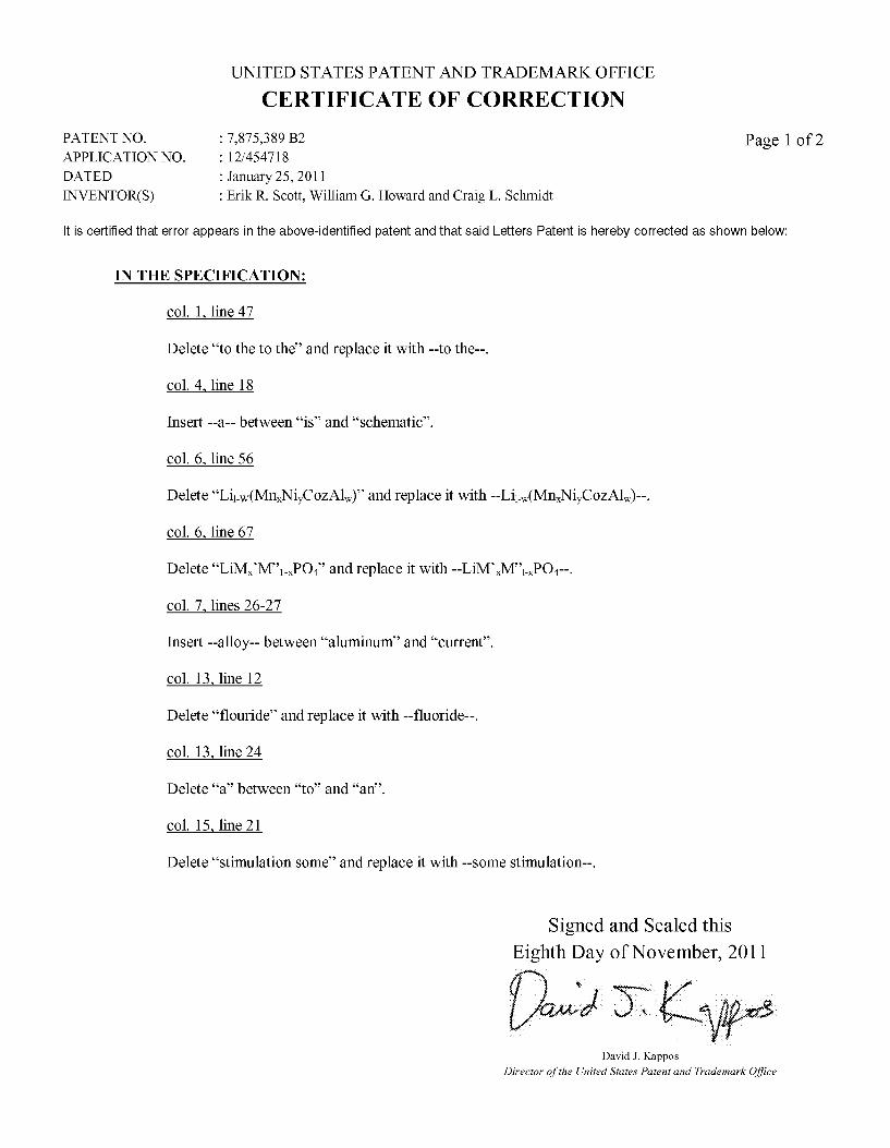
UNITED STATES PATENT AND TRADEMARK OFFICE
CERTIFICATE OF CORRECTION
PATENT NO. : 7,875,389 B2 Page 1 of 2 APPLICATIONNO. : 12/454718 DATED : January 25, 2011 INVENTOR(S) : Erik R. Scott, William G. Howard and Craig L. Schmidt
It is certified that error appears in the above-identified patent and that said Letters Patent is hereby corrected as shown below:
IN THE SPECIFICATION:
col. 1 line 47
Delete “to the to the and replace it with--to the--.
col. 4 line 18
Insert --a-- between “is and “Schematic.
col. 6, line 56
Delete “Liw(Mn,NiCoZAlw) and replace it with --Lilw(Mn,NiCoZAlw)--.
col. 6, line 67
Delete “LiMM-PO, and replace it with --LiMMPO4--.
col. 7, lines 26-27
Insert --alloy-- between “aluminum and “current.
col. 13 line 12
Delete “flouride' and replace it with --fluoride--.
col. 13 line 24
Delete “a between “to and “an.
col. 15, line 21
Delete “stimulation some and replace it with --some stimulation--.
Signed and Sealed this Eighth Day of November, 2011
David J. Kappos Director of the United States Patent and Trademark Office

CERTIFICATE OF CORRECTION (continued) Page 2 of 2 U.S. Pat. No. 7,875,389 B2
IN THE CLAIMS:
Claim 21 col. 17 line 46
Delete the word “carbone and replace it with --carbonate--.
Claim 32 col. 18 line 33
Delete the word “carbone and replace it with --carbonate--.