1117-16-018 Subgrade Exploration Report Engineer Senior Reviewer Attachments ... 5.3 Unsuitable...
32
Subgrade Exploration Smothers Road Roundabout Franklin/Delaware County, Ohio S&ME Project No. 1117-16-018 Prepared for: AECOM 277 West Nationwide Boulevard Columbus, OH 43215-2566 Prepared by: S&ME, Inc. 6190 Enterprise Court Dublin, OH 43016 May 13, 2016
Transcript of 1117-16-018 Subgrade Exploration Report Engineer Senior Reviewer Attachments ... 5.3 Unsuitable...
Subgrade Exploration
Smothers Road Roundabout
Franklin/Delaware County, Ohio
S&ME Project No. 1117-16-018
Prepared for:
AECOM
277 West Nationwide Boulevard
Columbus, OH 43215-2566
Prepared by:
S&ME, Inc.
6190 Enterprise Court
Dublin, OH 43016
May 13, 2016

S&ME, Inc. | 6190 Enterprise Court | Dublin, OH 43016 | p 614.793.2226 | f 614.793.2410 | www.smeinc.com
May 13, 2016
AECOM
277 West Nationwide Boulevard
Columbus, OH 43215-2566
Attention: Mr. Ed Kisiel, PE
Reference: Subgrade Exploration
Smothers Road Roundabout
Franklin & Delaware County, Ohio
S&ME Project No. 1117-16-018
Mr. Kisiel:
In accordance with our proposal dated November 20, 2015, which was authorized by AECOM Task Order
No. 73961 dated April 7, 2016, S&ME, Inc. (S&ME) has completed a Subgrade Exploration for the
proposed roundabout planned at the intersection of Smothers Road, Schott Road, and Red Bank Road
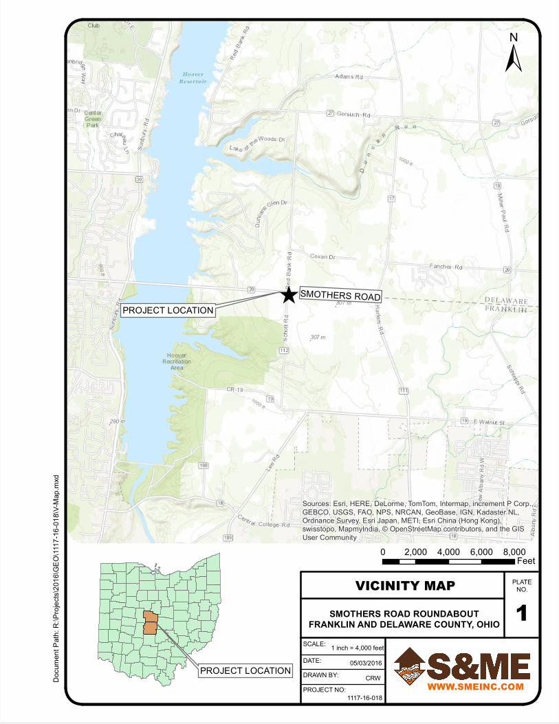
located in both Franklin and Delaware County, Ohio. The project location is illustrated on the Vicinity Map
included as Plate 1 in the Appendix of this report. Our report of this investigation is herewith submitted.
We appreciate having been given the opportunity to be of service on this project. If you require additional
assistance or have any questions, please feel free to contact our office at any time.
Respectfully,
S&ME, Inc.
Richard S. Weigand, PE Bethanie L. Meek, PE
Senior Engineer Senior Reviewer
Attachments: Appendix (17 sheets)
Submitted: 1 Email Copy

Subgrade Exploration
Smothers Road Roundabout
Franklin & Delaware County, Ohio
S&ME Project No. 1117-16-018
May 13, 2016 i
Table of Contents
1.0 Introduction............................................................................................................ 1
2.0 Geology and Observations of the Project......................................................... 1
2.1 Geology ....................................................................................................................................1
2.2 Reconnaissance .......................................................................................................................1
3.0 Exploration.............................................................................................................. 2
3.1 Field Investigation..................................................................................................................2
3.2 Laboratory Testing .................................................................................................................2
4.0 Findings................................................................................................................... 3
4.1 Existing Pavement ..................................................................................................................3
4.2 Subsurface Stratigraphy.........................................................................................................3
4.3 Groundwater Observations...................................................................................................3
5.0 Analyses and Recommendations ....................................................................... 4
5.1 Geotechnical Evaluation ........................................................................................................4
5.2 Subgrade Support Parameters ..............................................................................................4
5.3 Unsuitable Subgrade Materials ............................................................................................5
5.3.1 Silt ..............................................................................................................................5
5.3.2 Bedrock.......................................................................................................................5
5.3.3 Other Materials/Conditions.......................................................................................5
5.4 ODOT GB1 Subgrade Analysis.............................................................................................6
5.5 Additional Subgrade Remediation Considerations...........................................................7
5.6 Earthen Embankment Construction.....................................................................................7
5.6.1 Embankment Foundation Preparation.......................................................................8
5.6.2 Benching.....................................................................................................................9
5.6.3 Borrow Requirements and Compaction Criteria........................................................9
5.6.4 Compaction/Moisture Conditioning Concerns..........................................................9
5.6.5 Subgrade Preparation...............................................................................................10
5.7 Groundwater Considerations .............................................................................................10
6.0 Final Considerations........................................................................................... 10
Subgrade Exploration
Smothers Road Roundabout
Franklin & Delaware County, Ohio
S&ME Project No. 1117-16-018
May 13, 2016 ii
AppendixPlate No.
Important Information About Your Geotechnical Engineering Report.......................................................................1
Vicinity Map........................................................................................................................................................................................2
Plan of Borings ..................................................................................................................................................................................3
Explanation of Symbols and Terms (Soil and Rock) .......................................................................................................4-5
Boring Logs..................................................................................................................................................................................6-11
GB1: Subgrade Analyses Spreadsheet .................................................................................................................................. 12
ODOT Geotechnical Checklists ..........................................................................................................................................13-17
Subgrade Exploration
Smothers Road Roundabout
Franklin & Delaware County, Ohio
S&ME Project No. 1117-16-018
May 13, 2016 1
1.0 Introduction
S&ME understands that improvements, including the construction of a roundabout, are being planned for
the intersection of Smothers, Schott, and Red Bank Roads which is in both Franklin and Delaware County,
Ohio. The planned realignment of the legs of the intersection are planned to extend approximately 325
feet west, 475 feet east, 425 feet north, and 525 feet south of the intersection of the existing roadway
centerlines, with the new roundabout centered roughly 80 east of the existing intersection. Although
preliminary profile information was not available at the time of this report, AECOM has indicated that the
vertical alignment will be raised approximately 1 to 1.5 feet at the roundabout, with the majority of the
approach roadways remaining at approximately the same elevation as the existing grade.
This geotechnical exploration program was performed in general accordance with the ODOT
Specifications for Geotechnical Explorations (SGE) including the January 2016 updates, and ODOT
Geotechnical Bulletin GB1, “Plan Subgrades”, revised January 15, 2016.
2.0 Geology and Observations of the Project
2.1 Geology
The project site is located in a portion of Ohio which was glaciated, and is within the Galion Glaciated Low
Plateau physiographic region. This site is located just east of Hoover Reservoir in a transitional area of
rolling uplands with a layer of Wisconsin-aged glacial till overlying Mississippian-aged, Berea formation
sandstones over Bedford formation shale. Ohio Department of Natural Resources (ODNR) bedrock
topography mapping indicates that bedrock is located within roughly 5 to 15 feet of the existing ground
surface near this intersection. The ODNR “Ohio Karst Areas” map indicates that karst features are not
known to be present in the general area of the site.
2.2 Reconnaissance
A site reconnaissance visit was made on April 8, 2016, prior to the field exploration program. The land
usage along the majority of the project is either rural residential or agricultural, and the terrain is primarily
flat. Overhead wires were observed along the south side of Smothers Road, and an area with several
utility boxes was present just northeast of the existing intersection. The existing pavement condition of all
three roadways was generally noted to be in fair to good condition.
S&ME selected and marked the proposed boring locations during this site visit. Boring locations were
either painted on the existing pavement or staked using wooden lath and surveying ribbon in the farm
field to the southeast of the existing intersection (Boring B-002-0-16).

Subgrade Exploration
Smothers Road Roundabout
Franklin & Delaware County, Ohio
S&ME Project No. 1117-16-018
May 13, 2016 2
3.0 Exploration
3.1 Field Investigation
On April 14, 2016, a total of six (6) roadway borings were performed to investigate the subgrade soil for
the proposed intersection improvement. These borings were numbered B-001-0-16 through B-006-0-16,
and are hereinafter referred to as B-001 through B-006. The approximate locations of the borings are
shown on the Plan of Borings included as Plate 3 of the Appendix. Surveyed state plane coordinates and
ground surface elevations at the boring locations were provided to S&ME by AECOM.
The borings were performed by an ATV-mounted drilling rig using a 2¼-inch I.D. hollow-stem auger to
advance the borings between sampling attempts. At regular intervals, disturbed but representative soil
samples were obtained by lowering a 2-inch O.D. split-barrel sampler through the auger stem to the
bottom of the boring and then driving the sampler into the soil with blows from a 140-pound hammer
freely falling 30 inches (ASTM D1586 - Standard Penetration Test). Continuous SPT sampling was
performed in the four borings advanced through the existing pavement as little to no profile adjustment
was anticipated at these locations. The borings performed near the proposed roundabout were sampled
at 2½-foot intervals, as the final profile of the roundabout pavement was not known at the time of the
field work. In accordance with the current ODOT SGE, the hammer system on the drilling rig had been
calibrated in accordance with ASTM D 4633 to determine the drill rod energy ratio. This value (91%) is
included on each boring log.
At the completion of drilling, the borings were backfilled or sealed in accordance with Appendix F of the
ODOT SGE. Where borings were advanced through existing pavement, the surface of the pavement was
repaired using cold-patch asphalt. All recovered samples were transported to the soils laboratory of
S&ME for further examination and testing.
In the field, experienced S&ME personnel performed the following: 1) examined all samples recovered
from the borings; 2) preserved representative portions of all samples in airtight glass jars; 3) prepared a
log of each boring; 4) made seepage and groundwater observations; 5) made hand-penetrometer
measurements in soil specimens exhibiting cohesion; and, 6) provided liaison between the field work and
the Project Engineer so that the exploration program could be modified in the event unusual or
unexpected subsurface conditions were encountered.
3.2 Laboratory Testing
In the laboratory, all recovered soil samples were visually identified and tested for natural moisture
content. In addition, two (2) liquid and plastic limit determinations and gradation analyses were
performed on selected samples retrieved at or just below the anticipated subgrade level. The results of
these tests are reported numerically on the individual boring logs.
Based upon the results of the laboratory testing program, the field logs were modified, if necessary, and
copies of the laboratory corrected boring logs are submitted as Plates 6 through 11 of the Appendix.
Shown on these logs are: descriptions of the soil stratigraphy encountered; depths from which samples
were preserved; sampling efforts (blow-counts) required to obtain the specimens in the borings;
calculated N60 values; seepage and groundwater observations; and, values of hand-penetrometer
Subgrade Exploration
Smothers Road Roundabout
Franklin & Delaware County, Ohio
S&ME Project No. 1117-16-018
May 13, 2016 3
measurements made in soil samples exhibiting cohesion. For your reference, hand-penetrometer values
are roughly equivalent to the unconfined compressive strength of the cohesive fraction of the soil sample.
Soils have been classified in general accordance with Section 603 of the ODOT SGE, and described in
general accordance with Section 602. Bedrock descriptions in general accordance with Section 605 of the
SGE are also provided. An explanation of the symbols and terms used on the boring logs and the
definitions of the special adjectives used to denote the minor soil components is presented on Plates 3
and 4 of the Appendix.
4.0 Findings
4.1 Existing Pavement
Four (4) of the six (6) borings performed as part of this investigation were performed within the existing
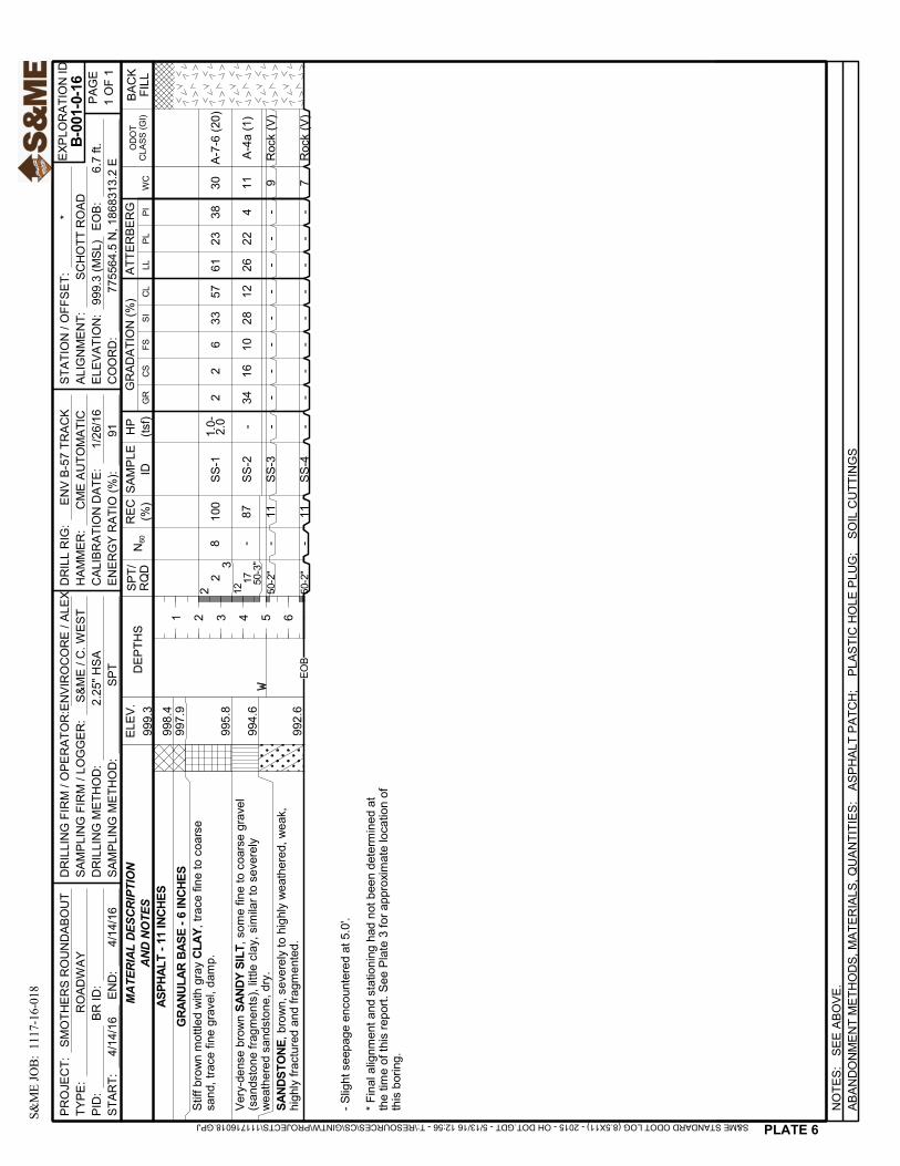
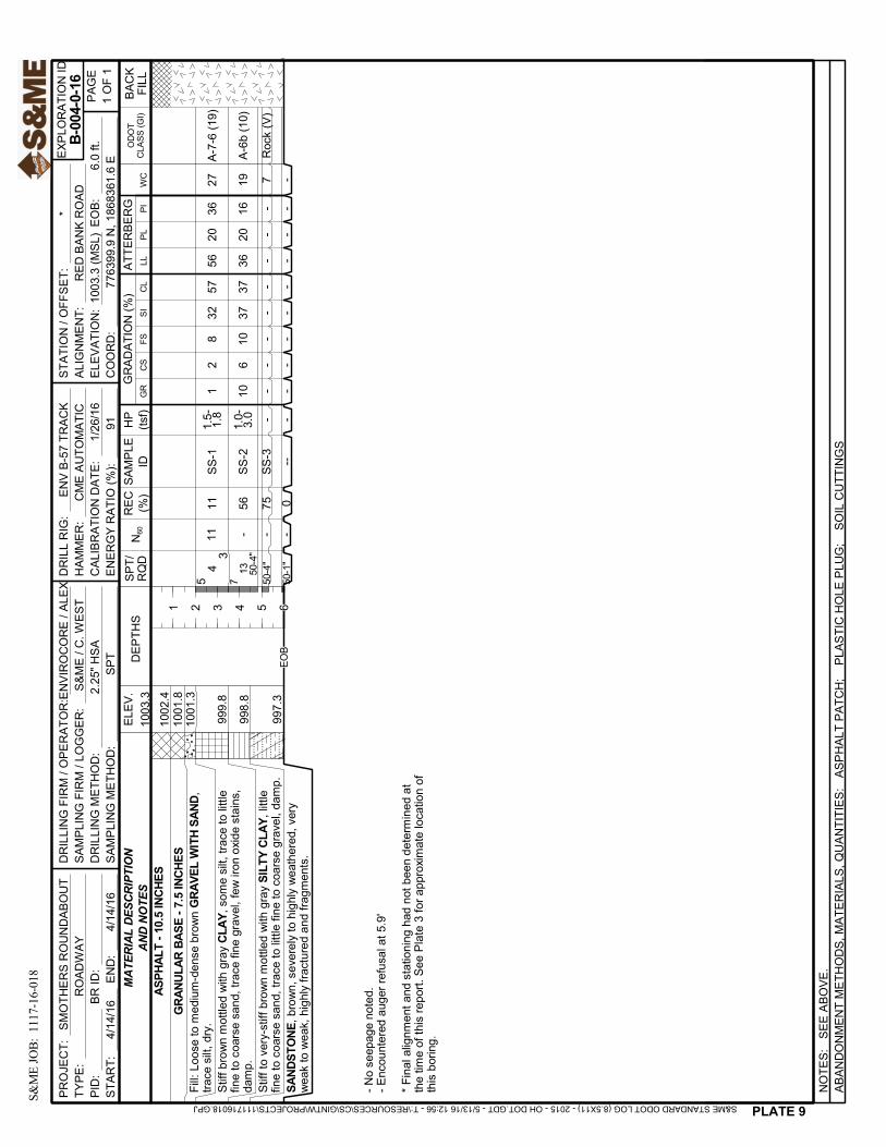
pavement of Smothers, Schott, or Red Bank Roads. Borings B-001 and B-004, advanced through Schott
and Red Bank Roads, respectively, encountered 11 and 10.5 inches of asphalt over 6 and 7.5 inches of
granular base. Borings B-005 and B-006 were drilled through the existing Smothers Road pavement and
encountered 13 and 10 inches of asphalt over 5 and 7 inches of granular base. Boring B-003, which was
drilled just north and east of the existing intersection in the partially paved area adjacent to the utility
boxes, encountered 6 inches of asphalt over 7 inches of granular base.
4.2 Subsurface Stratigraphy
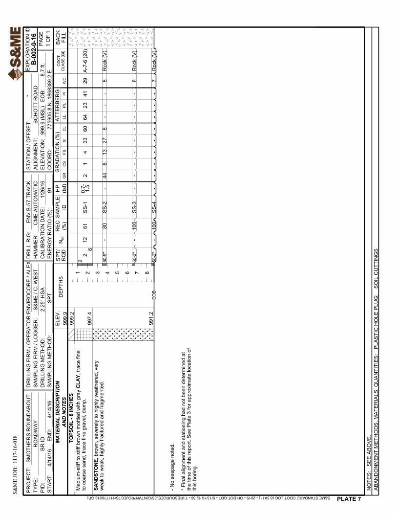
Beneath 8 inches of topsoil and rootmat in Boring B-002, and beneath the pavement sections in Borings
B-001, B-003, B-004, and B-006, the borings encountered cohesive soil consisting of medium-stiff to very-
stiff brown mottled with gray CLAY (A-7-6) and SILTY CLAY (A-6b). N60 values in these materials generally
ranged from 8 to 18, and Group Index values ranged from 10 to 20. In Boring B-006, this cohesive layer
was overlain by 1.1 feet of slightly organic SILT (A-4b). Boring B-005 also encountered cohesive soil (A-6a
and A-6b); however, this soil was described as existing fill.
Beneath this upper cohesive soil, Borings B-001 and B-003 encountered a granular layer consisting of
very-dense SANDY SILT (A-4a) containing numerous sandstone fragments and described as being similar
to severely weathered sandstone, and Boring B-005 encountered very-dense GRAVEL WITH SAND. Boring
B-005 was terminated within this layer.
Borings B-001 through B-004 and Boring B-006 were terminated after penetrating 1.5 to 6.2 feet into
SANDSTONE which was described as being severely to highly weathered, very-weak to weak, and highly
fractured and fragmented.
4.3 Groundwater Observations
During drilling, groundwater was noted in Borings B-001 and B-003 at the depths of 5.0 and 6.0 feet,
respectively. At the completion of drilling, no measureable amount of water had accumulated in Boring
B-001, but had accumulated inside the auger stem to a depth of 4.8 feet below the ground surface in
Boring B-003. No groundwater seepage was noted in the remaining four borings.

Subgrade Exploration
Smothers Road Roundabout
Franklin & Delaware County, Ohio
S&ME Project No. 1117-16-018
May 13, 2016 4
5.0 Analyses and Recommendations
5.1 Geotechnical Evaluation
S&ME understands that it is proposed to improve the intersection of Smothers Road with Schott and Red
Bank Roads in Franklin and Delaware County, Ohio, by providing a roundabout. Roadway improvements
and reconstruction will extend approximately 325 feet west, 475 feet east, 425 feet north, and 525 feet
south of the existing intersection, with the new roundabout centered approximately 80 feet east of the
existing intersection. Preliminary information from AECOM indicates the proposed profile near the
roundabout will be raised slightly (1 to 1.5 feet), with the majority of the approach roadways remaining at
approximately the same elevation as the existing grade. New fill placement will also be required where
the alignment crosses existing ditches that parallel the current roadways.
5.2 Subgrade Support Parameters
Plate 12 in the Appendix is an ODOT Geotechnical Bulletin GB1 spreadsheet (Ver. 13.00) created by the
ODOT Office of Geotechnical Engineering (OGE) to summarize the soil type (by ODOT/HRB classification),
group indices, depth, blow-counts, and Atterberg Limit values of the proposed subgrade soils
encountered in the borings drilled for this project. This table also computes an average of the estimated
values of the California Bearing Ratio (CBR) for the soils encountered at or below the anticipated subgrade
level of the proposed roadway profile.
Based on the preliminary profile information provided verbally by AECOM at the time of this report, the
following average California Bearing Ratio (CBR) is computed by the ODOT GB1 spreadsheet for the
anticipated subgrade soils encountered during this investigation:
CBR: 5%
Based on this average value, and Section 203.1 of the current ODOT Pavement Design Manual, the
following value of Resilient Modulus (MR) may be used during new pavement section design for this
project.
MR: 6,000 psi
These subgrade support values may be used during pavement design for this project provided that the
entire proposed pavement subgrade is prepared in strict accordance with Item 204 of the 2016 ODOT
Construction and Materials Specifications (CMS), and that all borrow soil placed within 3 feet of the final
subgrade level of a new fill embankment is capable of providing average subgrade support parameters
which meet or exceed the above values. This subgrade evaluation also assumes that the subgrade for the
new roadways is composed of the materials encountered in the borings. If, at the time of construction, it
is determined that the subgrade consists of materials different than those encountered in the borings, the
pavement design subgrade criteria should be reviewed and, if necessary, modified.

Subgrade Exploration
Smothers Road Roundabout
Franklin & Delaware County, Ohio
S&ME Project No. 1117-16-018
May 13, 2016 5
5.3 Unsuitable Subgrade Materials
5.3.1 Silt
Boring B-006 encountered 1.1 feet of frost-susceptible silt soil with an ODOT classification of A-4b
immediately beneath the existing granular base of Smothers Road. In accordance with Item 203.03.A of
the 2016 ODOT CMS, soil with this classification (A-4b) is not permitted within 3 feet of the subgrade
level. Therefore, it is recommended that this soil type be completely overexcavated where present to
depths less than 3 feet, or be removed to a depth of at least 3 feet below the proposed subgrade level if
thicker deposits are present, and the overexcavation replaced with acceptable borrow soil (see “Borrow
Requirements and Compaction Criteria” section on page 9 of this report). This A-4b soil was also
described as being slightly organic.
5.3.2 Bedrock
Five of the six borings performed for this project encountered very-weak to weak and severely weathered
sandstone bedrock. In Borings B-001 and B-003, the sandstone was overlain by 1.2 to 2.5 feet of very-
dense brown SANDY SILT which contained gravel consisting of sandstone fragments and was described as
being similar to severely weathered and degraded sandstone. None of the borings, however,
encountered either sandstone or the very-dense SANDY SILT containing sandstone fragments within 2
feet of the estimated roadway subgrade based on the estimated profile information provided by AECOM.
Because of the wide spacing of the explorations, however, it is possible that bedrock may be present at
elevations higher than that encountered in the borings. If areas of bedrock are encountered where the
rock is within 2 feet of the bottom of the pavement materials, it will be necessary to overexcavate the
bedrock to a depth in accordance with ODOT CMS Item 204.05 (i.e., undercut to at least 2 feet below the
bottom of asphalt or concrete pavement). This overexcavated material must be replaced with compacted,
suitable embankment material (ODOT CMS Item 203.02) meeting the minimum subgrade support
characteristics consistent with the design CBR for the pavement section (see Section 4.2).
Based on the results of the borings, S&ME recommends that provisions for encountering bedrock be
made where excavations for utilities or other aspects of this project extend more than 2 to 3 feet below
the proposed roadway subgrade level.
Although several of the borings were able to penetrate a few feet into the bedrock before encountering
“auger refusal”, it must be emphasized that a direct correlation should not be made between the
performance of the drilling rig and the ability of construction equipment to excavate the bedrock
at this site.
5.3.3 Other Materials/Conditions
None of the borings performed during this investigation encountered any other soil which ODOT GB1
considers to be unsuitable either by classification (A-2-5, A-5, A-7-5, A-8a, A-8b) or which has a Liquid
Limit value in excess of 65%.
Subgrade Exploration
Smothers Road Roundabout
Franklin & Delaware County, Ohio
S&ME Project No. 1117-16-018
May 13, 2016 6
If deposits of unsuitable soils such as topsoil, silt, or organic materials are encountered during earthwork
or proofrolling operations, S&ME recommends that test pits or hand sampling methods be used to
further investigate and delineate the extent of these deposits.
Existing underground utility lines are present beneath or adjacent to the existing roadways, and the type
of material used and the relative compactness of backfill within any such utility trenches are unknown.
Some instability of utility trench backfill may occur during earthwork operations and/or proofrolling, and
some recompaction of granular utility trench backfill may become necessary. Additionally, if water has
accumulated within the utility backfill, the subgrade soil in the vicinity of any saturated utility trenches
may have become sufficiently weak, soft, and/or wet that proofrolling may identify these additional areas
as requiring overexcavation and replacement. In any case, care should be taken not to disturb any
shallow utilities during proofrolling and overexcavation activities.
Particular attention should also be given to the ditches and drainage swales adjacent to the existing
roadways, as unstable or unsuitable (e.g., soft, saturated, possibly organic) soil requiring removal may be
present in the ditches or swales. S&ME recommends that these areas be closely examined and the
bottoms of the ditches probed prior to commencing earthwork operations, and all weak, wet, or organic
soil should be removed prior to commencing fill placement. For this reason, AECOM may consider
including a 1- to 2-foot deep overexcavation of existing ditches in the project excavation quantities.
These ditch overexcavations should be backfilled with properly compacted soil (ODOT CMS Item 203, or
Item 204 if within 12 inches of proposed subgrade).
Because of the variable nature of the wide spacing of the explorations, it is possible that other areas of
unsuitable organic or silt materials that were not encountered in any of the borings may be encountered
during earthwork and proofrolling operations. Visual observation of the proofrolling procedures by the
Geotechnical Engineer of Record may potentially result in a reduction of overexcavation of unsuitable soils
in these areas. Additionally, S&ME recommends that construction traffic be minimized or restricted once
the planned soil subgrade level has been exposed or attained.
5.4 ODOT GB1 Subgrade Analysis
ODOT’s Geotechnical Bulletin GB1 “Plan Subgrades” indicates that a comparison of the laboratory-
measured moisture content to the estimated optimum moisture content of the subgrade soil, along with
the normalized blow-count (N60) from SPT sampling, may be used as an indicator of the potential need for
subgrade treatment or remediation of unstable subgrade soil. The acceptable options presented by GB1
to remediate and establish a stable soil subgrade are either to “excavate and replace”, or chemical
stabilization.
Plate 12 in the Appendix summarizes the laboratory-measured moisture content of the samples obtained
from each boring with respect to their estimated optimum moisture contents, along with the lowest N
value (N60L) obtained from the Standard Penetration Tests performed in each of these borings. This table
also indicates the recommended Item 204 “excavate and replace” depths per GB1 at each boring location,
along with an overall assessment of the suitability of various types of chemical stabilization on this project.
Plate 12 indicates that 67% (4 of 6) of the borings performed as part of this investigation encountered soil
at or just below the proposed subgrade level with characteristics defined as problematic (excessive soil
Subgrade Exploration
Smothers Road Roundabout
Franklin & Delaware County, Ohio
S&ME Project No. 1117-16-018
May 13, 2016 7
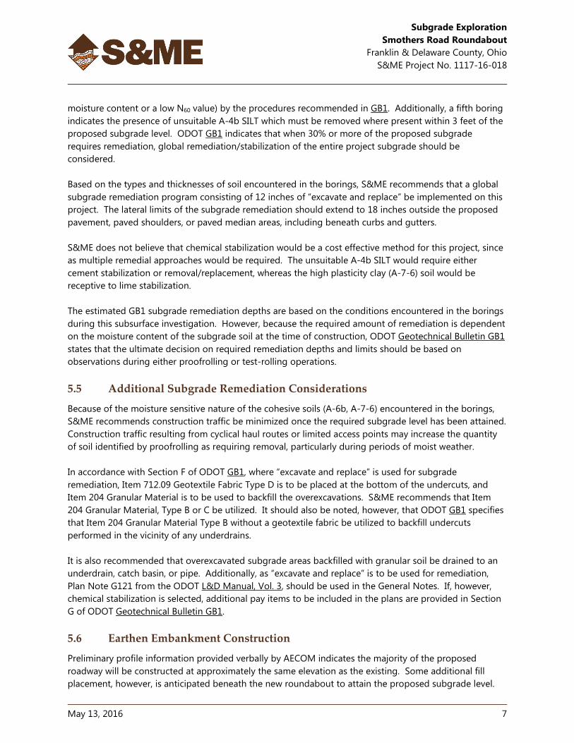
moisture content or a low N60 value) by the procedures recommended in GB1. Additionally, a fifth boring
indicates the presence of unsuitable A-4b SILT which must be removed where present within 3 feet of the
proposed subgrade level. ODOT GB1 indicates that when 30% or more of the proposed subgrade
requires remediation, global remediation/stabilization of the entire project subgrade should be
considered.
Based on the types and thicknesses of soil encountered in the borings, S&ME recommends that a global
subgrade remediation program consisting of 12 inches of “excavate and replace” be implemented on this
project. The lateral limits of the subgrade remediation should extend to 18 inches outside the proposed
pavement, paved shoulders, or paved median areas, including beneath curbs and gutters.
S&ME does not believe that chemical stabilization would be a cost effective method for this project, since
as multiple remedial approaches would be required. The unsuitable A-4b SILT would require either
cement stabilization or removal/replacement, whereas the high plasticity clay (A-7-6) soil would be
receptive to lime stabilization.
The estimated GB1 subgrade remediation depths are based on the conditions encountered in the borings
during this subsurface investigation. However, because the required amount of remediation is dependent
on the moisture content of the subgrade soil at the time of construction, ODOT Geotechnical Bulletin GB1
states that the ultimate decision on required remediation depths and limits should be based on
observations during either proofrolling or test-rolling operations.
5.5 Additional Subgrade Remediation Considerations
Because of the moisture sensitive nature of the cohesive soils (A-6b, A-7-6) encountered in the borings,
S&ME recommends construction traffic be minimized once the required subgrade level has been attained.
Construction traffic resulting from cyclical haul routes or limited access points may increase the quantity
of soil identified by proofrolling as requiring removal, particularly during periods of moist weather.
In accordance with Section F of ODOT GB1, where “excavate and replace” is used for subgrade
remediation, Item 712.09 Geotextile Fabric Type D is to be placed at the bottom of the undercuts, and
Item 204 Granular Material is to be used to backfill the overexcavations. S&ME recommends that Item
204 Granular Material, Type B or C be utilized. It should also be noted, however, that ODOT GB1 specifies
that Item 204 Granular Material Type B without a geotextile fabric be utilized to backfill undercuts
performed in the vicinity of any underdrains.
It is also recommended that overexcavated subgrade areas backfilled with granular soil be drained to an
underdrain, catch basin, or pipe. Additionally, as “excavate and replace” is to be used for remediation,
Plan Note G121 from the ODOT L&D Manual, Vol. 3, should be used in the General Notes. If, however,
chemical stabilization is selected, additional pay items to be included in the plans are provided in Section
G of ODOT Geotechnical Bulletin GB1.
5.6 Earthen Embankment Construction
Preliminary profile information provided verbally by AECOM indicates the majority of the proposed
roadway will be constructed at approximately the same elevation as the existing. Some additional fill
placement, however, is anticipated beneath the new roundabout to attain the proposed subgrade level.

Subgrade Exploration
Smothers Road Roundabout
Franklin & Delaware County, Ohio
S&ME Project No. 1117-16-018
May 13, 2016 8
5.6.1 Embankment Foundation Preparation
Prior to commencing earthwork operations, it is recommended that all existing pavement, granular base,
sod, topsoil, vegetation, and other miscellaneous materials be completely removed from the entire
footprint of the proposed roadway embankments. Following the removal of these materials, it is
recommended that the entire exposed subgrade and embankment foundation surface be examined by
the Geotechnical Engineer of Record or their designated representative to identify any weak, wet, organic,
or otherwise unsuitable soils that were not encountered during the subsurface investigation, especially in
“at-grade” and fill areas. Any such materials identified should be removed and replaced with suitable
compacted fill (Item 203, or Item 204 when within 12 inches of the proposed subgrade).
Recommendations for existing ditches have been previously presented in Section 5.3, “Unsuitable
Subgrade Materials” of this report.
5.6.1.1 “Fill” Areas
Because the realigned roadways will require a thin layer of new fill to be placed in a few areas, S&ME
recommends that consideration be given to test rolling the exposed embankment foundation prior to
commencing fill placement in these areas. This additional proofrolling, performed in accordance with
Item 204.06 of the 2016 ODOT CMS and Section 204 of the 2013 ODOT Construction Inspection Manual
of Procedures, would assist in identifying soft, wet or weak zones that may be present in areas where the
thickness of new fill embankment is insufficient to “bridge” an underlying weak or wet soil. If any such
zones are present, the materials contained in these zones should be either scarified, dried, and thoroughly
recompacted in place in accordance with ODOT Item 203.07, or be removed and the overexcavation filled
in a controlled manner with compacted, suitable embankment material (Item 203.02) and the
recommendations presented in the following section of this report.
Although Item 203.05 permits the use of a “bridge lift” to aid in spanning soft or wet foundation areas,
S&ME recommends that this practice not be permitted except where more than 3 feet of new
embankment fill placement is required. Soft, weak, wet, or unsuitable soils that are not removed from
beneath a thin layer of fill may result in significant difficulties in achieving the compaction percentages
required for the new fill (Items 203.07 or 204.03) such that final subgrade acceptance proofrolling may
require overexcavation of the new fill where weak soils were “bridged” by a minimal thickness of new fill.
Additionally, even if more than 3 feet of new fill is required in existing roadway ditches, S&ME does not
recommend that bridge lift be permitted in these areas because of the potential for organic soil in the
existing ditches. Long term settlement within any organic soil left in the existing ditch lines may result in
the development of a depression in the pavement surface.
5.6.1.2 “At-Grade” and “Cut” Areas
Once the desired subgrade elevation has been attained in all “cut” and “at-grade” areas, and after
overexcavation of all existing unsuitable subgrade materials has been completed, the subgrade soil
beneath the entire roadway and shoulder pavement area should be scarified and recompacted to a depth
of 12 inches below the subgrade level in accordance with ODOT Item 204.03. During recompaction, the
moisture content of the subgrade soil should be maintained or adjusted in accordance with ODOT Item
203.07.A.
Subgrade Exploration
Smothers Road Roundabout
Franklin & Delaware County, Ohio
S&ME Project No. 1117-16-018
May 13, 2016 9
Following the completion of the scarification and recompaction of the subgrade in these “cut” and “at-
grade” areas, it is strongly recommended that construction traffic be restricted from traveling on the
compacted subgrade until final acceptance proofrolling has been performed. Cohesive subgrade soils
subjected to repeated moisture fluctuations, which may occur as a result of exposure to rainfall and/or
surface water runoff, may exhibit subgrade instability.
5.6.2 Benching
Where new fill is to be placed on an existing ground surface with a slope that is between 4(H):1(V) and
8(H):1(V), benching of the existing ground surface should be performed in accordance with Item 203.05 of
the ODOT CMS. However, at any locations where the existing ground surface is steeper than 4(H):1(V),
“Special Benching” should be performed in accordance with the procedures outlined in the current ODOT
Geotechnical Bulletin GB2, “Special Benching and Sidehill Embankment Fills”, and the ODOT Construction
Inspection Manual of Procedures.
As stated in the ODOT Geotechnical Bulletin GB2, wherever “Special Benching” is used, Plan Note G109
from the ODOT L&D Manual, Vol. 3, should be included in the General Notes.
5.6.3 Borrow Requirements and Compaction Criteria
New fill should consist of inorganic soil free of all miscellaneous materials, cobbles, and boulders, which is
placed in uniform, thin layers and then compacted in accordance with either Item 203, “Roadway
Excavation and Embankment”, or when within 12 inches of the proposed subgrade level, Item 204
“Subgrade Compaction and Proofrolling”, of the ODOT CMS. Borrow materials should not be placed in a
frozen condition or upon a frozen surface, and any sloping surfaces on which new fill is to be placed
should first be benched in accordance with either Item 203.05 or ODOT GB2, depending on the slope of
the existing ground surface at each location.
Also, as recommended in Section 5.2 of this report, any borrow materials to be used as new fill or backfill
within 3 feet of the proposed subgrade level be tested in the laboratory to determine that the borrow
materials are capable of exhibiting subgrade support characteristics that are no less than the CBR value
used during the pavement design.
Compaction requirements for the construction of earthen embankments are based on ODOT CMS Item
203.07.B (or Item 204.03 when within 12 inches of subgrade level), which specifies a minimum percent
compaction based on the dry unit weight of the type of soil fill being placed as borrow. At the time of
this submittal, it is unknown if a borrow source will be required for this project. S&ME recommends that,
if a borrow site is required, that sampling and testing of this borrow material be performed prior to
construction to verify that the borrow soils are suitable for the planned construction.
5.6.4 Compaction/Moisture Conditioning Concerns
The cohesive soils encountered in the borings performed for this project, if exposed to inclement weather
or rainfall, may rapidly absorb additional moisture and weaken. It is imperative that these soil types not
be exposed to rainfall while in a loosened state (such as during discing and drying for moisture
conditioning during fill placement). Should these materials become sufficiently saturated that additional
moisture conditioning is impractical, the material should be wasted. Therefore, it is recommended that

Subgrade Exploration
Smothers Road Roundabout
Franklin & Delaware County, Ohio
S&ME Project No. 1117-16-018
May 13, 2016 10
moisture conditioning only be performed when extended periods of suitable weather are anticipated, and
that only the amount of borrow soil be exposed that may be moisture conditioned and properly
compacted during suitable weather periods.
5.6.5 Subgrade Preparation
Once the design subgrade elevation has been attained for the proposed roadway embankments, the
subgrade should be compacted and proofrolled in accordance with Item 204 of the ODOT Construction
and Material Specifications, with any weak or unsuitable areas repaired in accordance with Item 204.07.
5.7 Groundwater Considerations
Based upon observations made at the time of this investigation, significant groundwater problems are not
anticipated in connection with the proposed roadway improvements and extension. The new roadway
subgrade should be graded to prevent surface runoff from pooling on the cohesive soils during
construction as exposure of cohesive soils to moisture will result in a decrease in strength and an increase
in compressibility. Soil softened by standing water or disturbed by construction activities should be
removed before proceeding with construction.
The presence of water bearing granular layers or seams in the walls of any excavation may also result in
caving or sloughing of the excavation walls. S&ME recommends that all excavations be braced, or sloped
back at a safe angle, in accordance with current OSHA Excavation Regulations.
6.0 Final Considerations
The analyses, conclusions and recommendations presented in this report are based on project information
provided by AECOM. We request that S&ME be retained to review the final design plans and
specifications to verify that the intent of our engineering recommendations have been properly
incorporated into the design documents. It is also recommended that S&ME be retained to observe the
subgrade proofrolling and roadway subgrade construction for the project to confirm that our
recommendations are valid or to modify them accordingly. S&ME cannot assume responsibility or liability
for the adequacy of recommendations if S&ME is not retained to observe construction.
The contents of this report are also based on the subsurface conditions as they existed at the time of our
field investigation, and further on the assumption that the exploratory borings are representative of actual
subsurface conditions throughout the area investigated. It should be noted that actual subsurface
conditions between and beyond the borings might differ from those encountered at the boring locations.
If subsurface conditions varying from those discussed in this report are encountered during construction,
S&ME should be notified immediately so that we may evaluate the effects, if any, on design and
construction.

Subgrade Exploration
Smothers Road Roundabout
Franklin & Delaware County, Ohio
S&ME Project No. 1117-16-018
Appendix
Portion obtained with permission from “Important Information About Your Geotechnical Engineering Report”, ASFE, 2004 © S&ME, Inc. 2010
Important Information About Your
Geotechnical Engineering Report
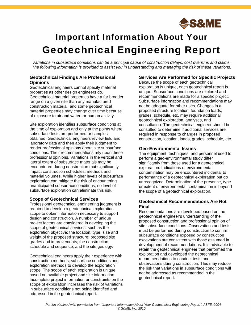
Variations in subsurface conditions can be a principal cause of construction delays, cost overruns and claims. The following information is provided to assist you in understanding and managing the risk of these variations.
Geotechnical Findings Are Professional Opinions Geotechnical engineers cannot specify material properties as other design engineers do. Geotechnical material properties have a far broader range on a given site than any manufactured construction material, and some geotechnical material properties may change over time because of exposure to air and water, or human activity. Site exploration identifies subsurface conditions at the time of exploration and only at the points where subsurface tests are performed or samples obtained. Geotechnical engineers review field and laboratory data and then apply their judgment to render professional opinions about site subsurface conditions. Their recommendations rely upon these professional opinions. Variations in the vertical and lateral extent of subsurface materials may be encountered during construction that significantly impact construction schedules, methods and material volumes. While higher levels of subsurface exploration can mitigate the risk of encountering unanticipated subsurface conditions, no level of subsurface exploration can eliminate this risk. Scope of Geotechnical Services Professional geotechnical engineering judgment is required to develop a geotechnical exploration scope to obtain information necessary to support design and construction. A number of unique project factors are considered in developing the scope of geotechnical services, such as the exploration objective; the location, type, size and weight of the proposed structure; proposed site grades and improvements; the construction schedule and sequence; and the site geology. Geotechnical engineers apply their experience with construction methods, subsurface conditions and exploration methods to develop the exploration scope. The scope of each exploration is unique based on available project and site information. Incomplete project information or constraints on the scope of exploration increases the risk of variations in subsurface conditions not being identified and addressed in the geotechnical report.
Services Are Performed for Specific Projects Because the scope of each geotechnical exploration is unique, each geotechnical report is unique. Subsurface conditions are explored and recommendations are made for a specific project. Subsurface information and recommendations may not be adequate for other uses. Changes in a proposed structure location, foundation loads, grades, schedule, etc. may require additional geotechnical exploration, analyses, and consultation. The geotechnical engineer should be consulted to determine if additional services are required in response to changes in proposed construction, location, loads, grades, schedule, etc. Geo-Environmental Issues The equipment, techniques, and personnel used to perform a geo-environmental study differ significantly from those used for a geotechnical exploration. Indications of environmental contamination may be encountered incidental to performance of a geotechnical exploration but go unrecognized. Determination of the presence, type or extent of environmental contamination is beyond the scope of a geotechnical exploration. Geotechnical Recommendations Are Not Final Recommendations are developed based on the geotechnical engineer’s understanding of the proposed construction and professional opinion of site subsurface conditions. Observations and tests must be performed during construction to confirm subsurface conditions exposed by construction excavations are consistent with those assumed in development of recommendations. It is advisable to retain the geotechnical engineer that performed the exploration and developed the geotechnical recommendations to conduct tests and observations during construction. This may reduce the risk that variations in subsurface conditions will not be addressed as recommended in the geotechnical report.
Sources: Esri, HERE, DeLorme, TomTom, Intermap, increment P Corp.,GEBCO, USGS, FAO, NPS, NRCAN, GeoBase, IGN, Kadaster NL,Ordnance Survey, Esri Japan, METI, Esri China (Hong Kong),swisstopo, MapmyIndia, © OpenStreetMap contributors, and the GISUser Community
Docu
ment
Path:
R:\P
rojec
ts\20
16\G
EO\11
17-16
-018\V
-Map
.mxd
0 2,000 4,000 6,000 8,000Feet
±
VICINITY MAPSMOTHERS ROAD ROUNDABOUT
FRANKLIN AND DELAWARE COUNTY, OHIO
PLATENO.1
WWW.SMEINC.COM1117-16-018
PROJECT NO:DRAWN BY: CRW
DATE:
SCALE:
05/03/20161 inch = 4,000 feet
PROJECT LOCATION
PROJECT LOCATION ^SMOTHERS ROAD
rweigand
Text Box
2

Ó́
Ó́Ó́
Ó́
Ó́
Ó́B-002-0-16
B-004-0-16
B-003-0-16
B-005-0-16B-006-0-16
B-001-0-16
AERIAL IMAGERY OBTAINED FROM THE OHIO GEOGRAPHICALLY REFERENCED INFORMATION PROGRAM'S (OGRIPS) 2014 OHIO STATEWIDE IMAGERY PROGRAM (OSIP II). ALL FEATURE LOCATIONSDISPLAYED ARE APPROXIMATED.
REFERENCE:
PLAN OF BORINGSSMOTHERS ROAD ROUNDABOUT
FRANKLIN AND DELAWARE COUNTY, OHIO1
1117-16-018
CRW
SCALE:
PROJECT NO:
DATE:
DRAWN BY:
PLATENO.
WWW.SMEINC.COMDocu
ment
Path:
R:\P
rojec
ts\20
16\G
EO\11
17-16
-018\1
117-1
6-018
POB.m
xd
0 400200Feet
±
Legend
Ó́ BORING LOCATION
1 inch = 200 feet5/5/2016
B-001-0-16
SMOTHERS ROAD
SCHO
TT R
OAD
RED
BANK
ROA
D
rweigand
Text Box
3

PLATE 3
EXPLANATION OF SYMBOLS AND TERMS USED ON BORING LOGSFOR SAMPLING AND DESCRIPTION OF SOIL
UUSAMPLING DATA
- Indicates sample was attempted within this depth interval.
- The number of blows required for each 6-inch increment of penetration of a “Standard”2-inch O.D. split-barrel sampler, driven a distance of 18 inches by a 140-poundhammer freely falling 30 inches (SPT). The raw “blowcount” or “N” is equal to the sumof the second and third 6-inch increments of penetration.
N60 - Corrected Blowcount = [(Drill Rod Energy Ratio) / (0.60 Standard)] X N
SS - Split-barrel sampler, any size.
ST - Shelby tube sampler, 3″ O.D., hydraulically pushed.
R - Refusal of sampler in very-hard or dense soil, or on a resistant surface.
50-3” - Number of blows (50) to drive a split-barrel sampler a certain distance (3 inches) otherthan the normal 6-inch increment.
DEPTH DATA
W - Depth of water or seepage encountered during drilling.
AD - Depth to water in boring after drilling (AD) is teminated.
5 days - Depth to water in a monitoring well, or a piezometer in a boring, a certain number ofdays (5) after termination of drilling.
TR - Depth to top of rock.
SOIL DESCRIPTIONSUU
Soils have been classified in general accordance with Section 603 of the most recent ODOTSGE, and described in general accordance with Section 602, including the use of specialadjectives to designate approximate percentages of minor components as follows:
UUAdjectiveUU UUPercent by WeightUU
tracelittle
some“and”
1 to 1010 to 2020 to 3535 to 50
The following terms are used to describe density and consistency of soils:
UUTerm (Granular Soils)UU UUBlows per foot (N60)UU
Very-looseLoose
Medium-denseDense
Very-dense
Less than 55 to 1011 to 3031 to 50Over 50
UUTerm (Cohesive Soils)UU UUQu (tsf)UU
Very-softSoft
Medium-stiffStiff
Very-stiffHard
Less than 0.250.25 to 0.50.5 to 1.01.0 to 2.02.0 to 4.0Over 4.0
23
5
rweigand
Text Box
PLATE 4
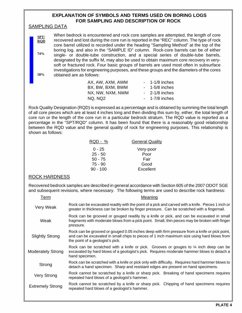
PLATE 4
EXPLANATION OF SYMBOLS AND TERMS USED ON BORING LOGS FOR SAMPLING AND DESCRIPTION OF ROCK
SAMPLING DATA
When bedrock is encountered and rock core samples are attempted, the length of core recovered and lost during the core run is reported in the “REC” column. The type of rock core barrel utilized is recorded under the heading “Sampling Method” at the top of the boring log, and also in the “SAMPLE ID” column. Rock-core barrels can be of either single- or double-tube construction, and a special series of double-tube barrels, designated by the suffix M, may also be used to obtain maximum core recovery in very-soft or fractured rock. Four basic groups of barrels are used most often in subsurface investigations for engineering purposes, and these groups and the diameters of the cores obtained are as follows:
AX, AW, AXM, AWM - 1-1/8 inches BX, BW, BXM, BWM - 1-5/8 inches
NX, NW, NXM, NWM - 2-1/8 inches NQ, NQ2 - 1-7/8 inches Rock Quality Designation (RQD) is expressed as a percentage and is obtained by summing the total length of all core pieces which are at least 4 inches long and then dividing this sum by, either, the total length of core run or the length of the core run in a particular bedrock stratum. The RQD value is reported as a percentage in the “SPT/RQD” column. It has been found that there is a reasonably good relationship between the RQD value and the general quality of rock for engineering purposes. This relationship is shown as follows:
RQD - % General Quality
0 - 25 Very-poor 25 - 50 Poor 50 - 75 Fair 75 - 90 Good
90 - 100 Excellent
ROCK HARDNESS
Recovered bedrock samples are described in general accordance with Section 605 of the 2007 ODOT SGE and subsequent revisions, where necessary. The following terms are used to describe rock hardness:
Term Meaning
Very Weak Rock can be excavated readily with the point of a pick and carved with a knife. Pieces 1 inch or greater in thickness can be broken by finger pressure. Can be scratched with a fingernail.
Weak Rock can be grooved or gouged readily by a knife or pick, and can be excavated in small fragments with moderate blows from a pick point. Small, thin pieces may be broken with finger pressure.
Slightly Strong Rock can be grooved or gouged 0.05 inches deep with firm pressure from a knife or pick point, and can be excavated in small chips to pieces of 1 inch maximum size using hard blows from the point of a geologist’s pick.
Moderately Strong Rock can be scratched with a knife or pick. Grooves or gouges to ¼ inch deep can be excavated by hard blows of a geologist’s pick. Requires moderate hammer blows to detach a hand specimen.
Strong Rock can be scratched with a knife or pick only with difficulty. Requires hard hammer blows to detach a hand specimen. Sharp and resistant edges are present on hand specimens.
Very Strong Rock cannot be scratched by a knife or sharp pick. Breaking of hand specimens requires repeated hard blows of a geologist’s hammer.
Extremely Strong Rock cannot be scratched by a knife or sharp pick. Chipping of hand specimens requires repeated hard blows of a geologist’s hammer.
SPT/RQD 74% 58%
rweigand
Text Box
PLATE 5
AS
PH
AL
T -
11
INC
HE
S
GR
AN
UL
AR
BA
SE
- 6
INC
HE
SS
tiff
brow
n m
ottle
d w
ith g
ray
CL
AY
, tr
ace
fine
to c
oars
esa
nd,
trac
e fin
e gr
avel
, da
mp.
Ver
y-de
nse
brow
n S
AN
DY
SIL
T,
som
e fin
e to
coa
rse
grav
el(s
ands
tone
fra
gmen
ts),
litt
le c
lay,
sim
ilar
to s
ever
ely
wea
ther
ed s
ands
tone
, dr
y.S
AN
DS
TO
NE
, br
own,
sev
erel
y to
hig
hly
wea
ther
ed,
wea
k,hi
ghly
frac
ture
d an
d fr
agm
ente
d.
- S
light
see
page
enc
ount
ered
at
5.0'
.
* F
inal
alig
nmen
t an
d st
atio
ning
had
not
bee
n de
term
ined
at
the
time
of t
his
repo
rt.
See
Pla
te 3
for
app
roxi
mat
e lo
catio
n of
this
bor
ing.
30 11 9 7
6 10 - -
2 34 - -
2 16 - -
38 4 - -
23 22 - -
61 26 - -
33 28 - -
998.
499
7.9
995.
8
994.
6
992.
6
22
312
17 50-3
"50
-2"
50-2
"
8 - - -
100
87 11 11
57 12 - -
1.0-
2.0 - - -
SS
-1
SS
-2
SS
-3
SS
-4
A-7
-6 (
20)
A-4
a (1
)
Roc
k (V
)
Roc
k (V
)
SA
MP
LIN
G M
ET
HO
D:
SP
T
PA
GE
1 O
F 1
999.
3
ELE
VA
TIO
N:
999.
3 (M
SL)
DR
ILLI
NG
ME
TH
OD
:2.
25"
HS
AS
TA
RT
:4/
14/1
6E
ND
:4/
14/1
6
SA
MP
LIN
G F
IRM
/ L
OG
GE
R:
S&
ME
/ C
. WE
ST
ALI
GN
ME
NT
:S
CH
OT
T R
OA
DD
RIL
LIN
G F
IRM
/ O
PE
RA
TO
R:E
NV
IRO
CO
RE
/ A
LEX
BR
ID:
PID
:
EX
PLO
RA
TIO
N ID
ST
AT
ION
/ O
FF
SE
T:
*
EO
B:
6.7
ft.
TY
PE
:R
OA
DW
AY
CA
LIB
RA
TIO
N D
AT
E:
1/26
/16
HA
MM
ER
:C
ME
AU
TO
MA
TIC
DR
ILL
RIG
:E
NV
B-5
7 T
RA
CK
B-0
01-0
-16
EN
ER
GY
RA
TIO
(%
):91
PR
OJE
CT
:S
MO
TH
ER
S R
OU
ND
AB
OU
T
CO
OR
D:
7755
64.5
N, 1
8683
13.2
E
MA
TE
RIA
L D
ES
CR
IPT
ION
AN
D N
OT
ES
WC
FS
GR
CS
PI
PL
LLS
I
ELE
V.
SP
T/
RQ
DB
AC
KF
ILL
DE
PT
HS
N60
RE
C(%
)
S&M
E J
OB
: 11
17-1
6-01
8
CL
HP
(tsf
)S
AM
PLE
IDO
DO
TC
LAS
S (
GI)
GR
AD
AT
ION
(%
)A
TT
ER
BE
RG
PLATE 6
S&ME STANDARD ODOT LOG (8.5X11) - 2015 - OH DOT.GDT - 5/13/16 12:56 - T:\RESOURCES\CS\GINTW\PROJECTS\111716018.GPJ
NO
TE
S:
SE
E A
BO
VE
.A
BA
ND
ON
ME
NT
ME
TH
OD
S,
MA
TE
RIA
LS,
QU
AN
TIT
IES
:A
SP
HA
LT P
AT
CH
;
PLA
ST
IC H
OLE
PLU
G;
S
OIL
CU
TT
ING
S
EO
B
1 2 3 4 5 6
TO
PS
OIL
- 8
INC
HE
SM
ediu
m-s
tiff
to s
tiff
brow
n m
ottle
d w
ith g
ray
CL
AY
, tr
ace
fine
to c
oars
e sa
nd, t
race
fin
e gr
avel
, dam
p.
SA
ND
ST
ON
E,
brow
n, s
ever
ely
to h
ighl
y w
eath
ered
, ve
ryw
eak
to w
eak,
hig
hly
frac
ture
d an
d fr
agm
ente
d.
- N
o se
epag
e no
ted.
* F
inal
alig
nmen
t an
d st
atio
ning
had
not
bee
n de
term
ined
at
the
time
of t
his
repo
rt.
See
Pla
te 3
for
app
roxi
mat
e lo
catio
n of
this
bor
ing.
29 8 8 7
4 13 - -
2 44 - -
1 8 - -
41 - - -
23 - - -
64 - - -
33 27 - -
999.
2
997.
4
991.
2
22
6
50-5
"
50-3
"
50-2
"
12 - - -
61 80 100
100
60 8 - -
0.7-
1.5 - - -
SS
-1
SS
-2
SS
-3
SS
-4
A-7
-6 (
20)
Roc
k (V
)
Roc
k (V
)
Roc
k (V
)
SA
MP
LIN
G M
ET
HO
D:
SP
T
PA
GE
1 O
F 1
999.
9
ELE
VA
TIO
N:
999.
9 (M
SL)
DR
ILLI
NG
ME
TH
OD
:2.
25"
HS
AS
TA
RT
:4/
14/1
6E
ND
:4/
14/1
6
SA
MP
LIN
G F
IRM
/ L
OG
GE
R:
S&
ME
/ C
. WE
ST
ALI
GN
ME
NT
:S
CH
OT
T R
OA
DD
RIL
LIN
G F
IRM
/ O
PE
RA
TO
R:E
NV
IRO
CO
RE
/ A
LEX
BR
ID:
PID
:
EX
PLO
RA
TIO
N ID
ST
AT
ION
/ O
FF
SE
T:
*
EO
B:
8.7
ft.
TY
PE
:R
OA
DW
AY
CA
LIB
RA
TIO
N D
AT
E:
1/26
/16
HA
MM
ER
:C
ME
AU
TO
MA
TIC
DR
ILL
RIG
:E
NV
B-5
7 T
RA
CK
B-0
02-0
-16
EN
ER
GY
RA
TIO
(%
):91
PR
OJE
CT
:S
MO
TH
ER
S R
OU
ND
AB
OU
T
CO
OR
D:
7759
05.8
N, 1
8683
89.2
E
MA
TE
RIA
L D
ES
CR
IPT
ION
AN
D N
OT
ES
WC
FS
GR
CS
PI
PL
LLS
I
ELE
V.
SP
T/
RQ
DB
AC
KF
ILL
DE
PT
HS
N60
RE
C(%
)
S&M
E J
OB
: 11
17-1
6-01
8
CL
HP
(tsf
)S
AM
PLE
IDO
DO
TC
LAS
S (
GI)
GR
AD
AT
ION
(%
)A
TT
ER
BE
RG
PLATE 7
S&ME STANDARD ODOT LOG (8.5X11) - 2015 - OH DOT.GDT - 5/13/16 12:56 - T:\RESOURCES\CS\GINTW\PROJECTS\111716018.GPJ
NO
TE
S:
SE
E A
BO
VE
.A
BA
ND
ON
ME
NT
ME
TH
OD
S,
MA
TE
RIA
LS,
QU
AN
TIT
IES
:P
LAS
TIC
HO
LE P
LUG
;
SO
IL C
UT
TIN
GS
EO
B
1 2 3 4 5 6 7 8

AS
PH
AL
T -
6 IN
CH
ES
GR
AN
UL
AR
BA
SE
- 7
INC
HE
SS
tiff
to v
ery-
stiff
bro
wn
mot
tled
with
gra
y C
LA
Y,
little
fine
toco
arse
san
d, t
race
fin
e gr
avel
, dam
p.
Ver
y-de
nse
brow
n S
AN
DY
SIL
T,
little
fine
to c
oars
e gr
avel
(san
dsto
ne f
ragm
ents
), s
ome
clay
, sim
ilar
to s
ever
ely
wea
ther
ed s
ands
tone
, dr
y.
SA
ND
ST
ON
E,
brow
n, s
ever
ely
to h
ighl
y w
eath
ered
, ve
ryw
eak
to w
eak,
hig
hly
frac
ture
d an
d fr
agm
ente
d, p
oorly
cem
ente
d.
- E
ncou
nter
ed w
ater
at
6.0'
.-
Wat
er a
ccum
ulat
ed t
o 4.
8' in
HS
A a
t com
plet
ion
of b
orin
g.
* F
inal
alig
nmen
t an
d st
atio
ning
had
not
bee
n de
term
ined
at
the
time
of t
his
repo
rt.
See
Pla
te 3
for
app
roxi
mat
e lo
catio
n of
this
bor
ing.
24 13 - -
12 16 - -
4 15 - -
5 6 - -
28 2 - -
22 24 - -
50 26 - -
27 42 - -
1001
.810
01.2
999.
3
996.
8
993.
6
23
5
50-4
"
50-3
"
50-3
"
12 - - -
56 75 33 33
52 21 - -
1.7-
3.5 - - -
SS
-1
SS
-2
SS
-3
SS
-4
A-7
-6 (
17)
A-4
a (6
)
Roc
k (V
)
Roc
k (V
)
SA
MP
LIN
G M
ET
HO
D:
SP
T
PA
GE
1 O
F 1
1002
.3
ELE
VA
TIO
N:
1002
.3 (
MS
L)D
RIL
LIN
G M
ET
HO
D:
2.25
" H
SA
ST
AR
T:
4/14
/16
EN
D:
4/14
/16
SA
MP
LIN
G F
IRM
/ L
OG
GE
R:
S&
ME
/ C
. WE
ST
ALI
GN
ME
NT
:R
ED
BA
NK
RO
AD
DR
ILLI
NG
FIR
M /
OP
ER
AT
OR
:EN
VIR
OC
OR
E /
ALE
X
BR
ID:
PID
:
EX
PLO
RA
TIO
N ID
ST
AT
ION
/ O
FF
SE
T:
*
EO
B:
8.7
ft.
TY
PE
:R
OA
DW
AY
CA
LIB
RA
TIO
N D
AT
E:
1/26
/16
HA
MM
ER
:C
ME
AU
TO
MA
TIC
DR
ILL
RIG
:E
NV
B-5
7 T
RA
CK
B-0
03-0
-16
EN
ER
GY
RA
TIO
(%
):91
PR
OJE
CT
:S
MO
TH
ER
S R
OU
ND
AB
OU
T
CO
OR
D:
7761
07.5
N, 1
8683
57.3
E
MA
TE
RIA
L D
ES
CR
IPT
ION
AN
D N
OT
ES
WC
FS
GR
CS
PI
PL
LLS
I
ELE
V.
SP
T/
RQ
DB
AC
KF
ILL
DE
PT
HS
N60
RE
C(%
)
S&M
E J
OB
: 11
17-1
6-01
8
CL
HP
(tsf
)S
AM
PLE
IDO
DO
TC
LAS
S (
GI)
GR
AD
AT
ION
(%
)A
TT
ER
BE
RG
PLATE 8
S&ME STANDARD ODOT LOG (8.5X11) - 2015 - OH DOT.GDT - 5/13/16 12:56 - T:\RESOURCES\CS\GINTW\PROJECTS\111716018.GPJ
NO
TE
S:
SE
E A
BO
VE
.A
BA
ND
ON
ME
NT
ME
TH
OD
S,
MA
TE
RIA
LS,
QU
AN
TIT
IES
:1
BA
G B
EN
TO
NIT
E C
HIP
S;
P
LAS
TIC
HO
LE P
LUG
;
SO
IL C
UT
TIN
GS
EO
BAD
1 2 3 4 5 6 7 8
AS
PH
AL
T -
10.
5 IN
CH
ES
GR
AN
UL
AR
BA
SE
- 7
.5 IN
CH
ES
Fill
: Lo
ose
to m
ediu
m-d
ense
bro
wn
GR
AV
EL
WIT
H S
AN
D,
trac
e si
lt, d
ry.
Stif
f br
own
mot
tled
with
gra
y C
LA
Y,
som
e si
lt, t
race
to li
ttle
fine
to c
oars
e sa
nd,
trac
e fin
e gr
avel
, fe
w ir
on o
xide
sta
ins,
dam
p.S
tiff
to v
ery-
stiff
bro
wn
mot
tled
with
gra
y S
ILT
Y C
LA
Y,
little
fine
to c
oars
e sa
nd,
trac
e to
litt
le f
ine
to c
oars
e gr
avel
, dam
p.S
AN
DS
TO
NE
, br
own,
sev
erel
y to
hig
hly
wea
ther
ed,
very
wea
k to
wea
k, h
ighl
y fr
actu
red
and
frag
men
ts.
- N
o se
epag
e no
ted.
- E
ncou
nter
ed a
uger
ref
usal
at
5.9'
* F
inal
alig
nmen
t an
d st
atio
ning
had
not
bee
n de
term
ined
at
the
time
of t
his
repo
rt.
See
Pla
te 3
for
app
roxi
mat
e lo
catio
n of
this
bor
ing.
27 19 7 -
8 10 - -
1 10 - -
2 6 - -
36 16 - -
20 20 - -
56 36 - -
32 37 - -
1002
.410
01.8
1001
.3
999.
8
998.
8
997.
3
54
37
13 50-4
"50
-4"
50-1
"
11 - - -
11 56 75 0
57 37 - -
1.5-
1.8
1.0-
3.0 - -
SS
-1
SS
-2
SS
-3 --
A-7
-6 (
19)
A-6
b (1
0)
Roc
k (V
)
SA
MP
LIN
G M
ET
HO
D:
SP
T
PA
GE
1 O
F 1
1003
.3
ELE
VA
TIO
N:
1003
.3 (
MS
L)D
RIL
LIN
G M
ET
HO
D:
2.25
" H
SA
ST
AR
T:
4/14
/16
EN
D:
4/14
/16
SA
MP
LIN
G F
IRM
/ L
OG
GE
R:
S&
ME
/ C
. WE
ST
ALI
GN
ME
NT
:R
ED
BA
NK
RO
AD
DR
ILLI
NG
FIR
M /
OP
ER
AT
OR
:EN
VIR
OC
OR
E /
ALE
X
BR
ID:
PID
:
EX
PLO
RA
TIO
N ID
ST
AT
ION
/ O
FF
SE
T:
*
EO
B:
6.0
ft.
TY
PE
:R
OA
DW
AY
CA
LIB
RA
TIO
N D
AT
E:
1/26
/16
HA
MM
ER
:C
ME
AU
TO
MA
TIC
DR
ILL
RIG
:E
NV
B-5
7 T
RA
CK
B-0
04-0
-16
EN
ER
GY
RA
TIO
(%
):91
PR
OJE
CT
:S
MO
TH
ER
S R
OU
ND
AB
OU
T
CO
OR
D:
7763
99.9
N, 1
8683
61.6
E
MA
TE
RIA
L D
ES
CR
IPT
ION
AN
D N
OT
ES
WC
FS
GR
CS
PI
PL
LLS
I
ELE
V.
SP
T/
RQ
DB
AC
KF
ILL
DE
PT
HS
N60
RE
C(%
)
S&M
E J
OB
: 11
17-1
6-01
8
CL
HP
(tsf
)S
AM
PLE
IDO
DO
TC
LAS
S (
GI)
GR
AD
AT
ION
(%
)A
TT
ER
BE
RG
PLATE 9
S&ME STANDARD ODOT LOG (8.5X11) - 2015 - OH DOT.GDT - 5/13/16 12:56 - T:\RESOURCES\CS\GINTW\PROJECTS\111716018.GPJ
NO
TE
S:
SE
E A
BO
VE
.A
BA
ND
ON
ME
NT
ME
TH
OD
S,
MA
TE
RIA
LS,
QU
AN
TIT
IES
:A
SP
HA
LT P
AT
CH
;
PLA
ST
IC H
OLE
PLU
G;
S
OIL
CU
TT
ING
S
EO
B
1 2 3 4 5 6

AS
PH
AL
T -
13
INC
HE
S
GR
AN
UL
AR
BA
SE
- 5
INC
HE
SF
ill:
Ver
y-st
iff t
o ha
rd b
row
n m
ottle
d w
ith g
ray
SIL
TY
CL
AY
,lit
tle fi
ne to
coa
rse
sand
, tra
ce f
ine
grav
el, d
amp.
Fill
: V
ery-
stiff
to
hard
bro
wn,
gra
y an
d re
d-br
own
SIL
T A
ND
CL
AY
, lit
tle fi
ne to
coa
rse
sand
, tr
ace
fine
grav
el,
dry.
Ver
y-de
nse
gray
and
bro
wn
GR
AV
EL
WIT
H S
AN
D,
little
silt
,fe
w s
ands
tone
fra
gmen
ts,
dry.
- N
o se
epag
e no
ted.
* F
inal
alig
nmen
t an
d st
atio
ning
had
not
bee
n de
term
ined
at
the
time
of t
his
repo
rt.
See
Pla
te 3
for
app
roxi
mat
e lo
catio
n of
this
bor
ing.
19 14 7 -
10 9 - -
5 8 - -
4 7 - -
17 14 - -
19 20 - -
36 34 - -
38 33 - -
1005
.710
05.3
1003
.8
1002
.3
1000
.5
34
84
8 1011 50
-5"
50-4
"
18 27 - -
61 89 67 0
43 43 - -
3.0-
4.5
4.0-
4.5 - -
SS
-1
SS
-2
SS
-3 --
A-6
b (1
1)
A-6
a (1
0)
A-1
-b (
V)
SA
MP
LIN
G M
ET
HO
D:
SP
T
PA
GE
1 O
F 1
1006
.8
ELE
VA
TIO
N:
1006
.8 (
MS
L)D
RIL
LIN
G M
ET
HO
D:
2.25
" H
SA
ST
AR
T:
4/14
/16
EN
D:
4/14
/16
SA
MP
LIN
G F
IRM
/ L
OG
GE
R:
S&
ME
/ C
. WE
ST
ALI
GN
ME
NT
:S
MO
TH
ER
S R
OA
DD
RIL
LIN
G F
IRM
/ O
PE
RA
TO
R:E
NV
IRO
CO
RE
/ A
LEX
BR
ID:
PID
:
EX
PLO
RA
TIO
N ID
ST
AT
ION
/ O
FF
SE
T:
*
EO
B:
6.3
ft.
TY
PE
:R
OA
DW
AY
CA
LIB
RA
TIO
N D
AT
E:
1/26
/16
HA
MM
ER
:C
ME
AU
TO
MA
TIC
DR
ILL
RIG
:E
NV
B-5
7 T
RA
CK
B-0
05-0
-16
EN
ER
GY
RA
TIO
(%
):91
PR
OJE
CT
:S
MO
TH
ER
S R
OU
ND
AB
OU
T
CO
OR
D:
7760
39.9
N, 1
8680
19.5
E
MA
TE
RIA
L D
ES
CR
IPT
ION
AN
D N
OT
ES
WC
FS
GR
CS
PI
PL
LLS
I
ELE
V.
SP
T/
RQ
DB
AC
KF
ILL
DE
PT
HS
N60
RE
C(%
)
S&M
E J
OB
: 11
17-1
6-01
8
CL
HP
(tsf
)S
AM
PLE
IDO
DO
TC
LAS
S (
GI)
GR
AD
AT
ION
(%
)A
TT
ER
BE
RG
PLATE 10
S&ME STANDARD ODOT LOG (8.5X11) - 2015 - OH DOT.GDT - 5/13/16 12:56 - T:\RESOURCES\CS\GINTW\PROJECTS\111716018.GPJ
NO
TE
S:
SE
E A
BO
VE
.A
BA
ND
ON
ME
NT
ME
TH
OD
S,
MA
TE
RIA
LS,
QU
AN
TIT
IES
:A
SP
HA
LT P
AT
CH
;
PLA
ST
IC H
OLE
PLU
G;
S
OIL
CU
TT
ING
S
EO
B
1 2 3 4 5 6

AS
PH
AL
T -
10
INC
HE
S
GR
AN
UL
AR
BA
SE
- 7
INC
HE
SP
ossi
ble
Fill
: M
ediu
m-d
ense
bro
wn
and
gray
SIL
T,
som
ecl
ay, l
ittle
fin
e to
coa
rse
sand
, tr
ace
fine
grav
el,
slig
htly
orga
nic,
dry
.S
tiff
to v
ery-
stiff
bro
wn
mot
tled
with
gra
y C
LA
Y,
som
e si
lt,tr
ace
to li
ttle
fin
e to
coa
rse
sand
, tr
ace
fine
grav
el,
dam
p.
Stif
f br
own
mot
tled
with
gra
y S
ILT
Y C
LA
Y,
little
to s
ome
fine
to c
oars
e sa
nd, t
race
fin
e to
coa
rse
grav
el, d
amp.
SA
ND
ST
ON
E,
brow
n, h
ighl
y w
eath
ered
, ve
ry w
eak
to w
eak,
high
ly fr
actu
red
and
frag
men
ted.
- S
ampl
es S
S-4
and
SS
-5 w
ere
obta
ined
from
an
offs
et b
orin
glo
cate
d im
med
iate
ly a
djac
ent
to B
-006
-0-1
6.-
Sam
ple
SS
-4: D
riven
fro
m 2
.5' -
4.0
'; S
PT
= 2
/2/4
; N60
= 9
- S
ampl
e S
S-5
: Driv
en f
rom
5.0
' - 6
.5';
SP
T =
4/2
/14;
N60
= 2
4
- N
o se
epag
e en
coun
tere
d.
* F
inal
alig
nmen
t an
d st
atio
ning
had
not
bee
n de
term
ined
at
the
time
of t
his
repo
rt.
See
Pla
te 3
for
app
roxi
mat
e lo
catio
n of
this
bor
ing.
6 19 26 31 19 26 -
- 8 7 - - - -
- 1 2 - - - -
- 6 11 - - - -
- 8 33 - - - -
- 20 22 - - - -
- 28 55 - - - -
- 54 30 - - - -
1002
.910
02.3
1001
.2
998.
7
997.
4
995.
0
146
6
22
3
50-4
"
50-2
"
18 8 - -
78 40 17 73 100 0
- 31 50 - - - -
-2.
5-4.
01.
2-1.
7
1.0-
1.7
1.2-
2.0
1.2-
2.0
SS
-1A
SS
-1B
SS
-4
SS
-2
SS
-5S
S-3 --
A-1
-b (
V)
A-4
b (8
)
A-7
-6 (
19)
A-7
-6 (
V)
A-6
b (V
)A
-6b
(V)
SA
MP
LIN
G M
ET
HO
D:
SP
T
PA
GE
1 O
F 1
1003
.7
ELE
VA
TIO
N:
1003
.7 (
MS
L)D
RIL
LIN
G M
ET
HO
D:
2.25
" H
SA
ST
AR
T:
4/14
/16
EN
D:
4/14
/16
SA
MP
LIN
G F
IRM
/ L
OG
GE
R:
S&
ME
/ C
. WE
ST
ALI
GN
ME
NT
:S
MO
TH
ER
S R
OA
DD
RIL
LIN
G F
IRM
/ O
PE
RA
TO
R:E
NV
IRO
CO
RE
/ A
LEX
BR
ID:
PID
:
EX
PLO
RA
TIO
N ID
ST
AT
ION
/ O
FF
SE
T:
*
EO
B:
8.7
ft.
TY
PE
:R
OA
DW
AY
CA
LIB
RA
TIO
N D
AT
E:
1/26
/16
HA
MM
ER
:C
ME
AU
TO
MA
TIC
DR
ILL
RIG
:E
NV
B-5
7 T
RA
CK
B-0
06-0
-16
EN
ER
GY
RA
TIO
(%
):91
PR
OJE
CT
:S
MO
TH
ER
S R
OU
ND
AB
OU
T
CO
OR
D:
7759
92.5
N, 1
8687
21.9
E
MA
TE
RIA
L D
ES
CR
IPT
ION
AN
D N
OT
ES
WC
FS
GR
CS
PI
PL
LLS
I
ELE
V.
SP
T/
RQ
DB
AC
KF
ILL
DE
PT
HS
N60
RE
C(%
)
S&M
E J
OB
: 11
17-1
6-01
8
CL
HP
(tsf
)S
AM
PLE
IDO
DO
TC
LAS
S (
GI)
GR
AD
AT
ION
(%
)A
TT
ER
BE
RG
PLATE 11
S&ME STANDARD ODOT LOG (8.5X11) - 2015 - OH DOT.GDT - 5/13/16 12:56 - T:\RESOURCES\CS\GINTW\PROJECTS\111716018.GPJ
NO
TE
S:
SE
E A
BO
VE
.A
BA
ND
ON
ME
NT
ME
TH
OD
S,
MA
TE
RIA
LS,
QU
AN
TIT
IES
:A
SP
HA
LT P
AT
CH
;
PLA
ST
IC H
OLE
PLU
G;
S
OIL
CU
TT
ING
S
EO
B
1 2 3 4 5 6 7 8

OD
OT
Geo
tech
nic
al
Bu
lleti
nG
B-1
Su
bg
rad
eA
naly
sis
Sp
read
sh
eet
Sm
oth
ers
Ro
ad
Ro
un
dab
ou
t,F
ran
kli
n/D
ela
ware
Co
un
ty,
Oh
io Surf
ace
Cla
ss
%S
urf
ace
Rig
320
R&
RR
1a
1b
33a
2-4
2-5
2-6
2-7
4a
4b
56a
6b
7-5
7-6
8a
8b
2-5
0N
60L<
=5
0%
83%
AV
.1
3.0
00
1/1
5/1
6206
CS
80
10
00
00
02
10
14
06
00
4b
117%
<=
10
33%
17%
67%
B
LS
35
%4
%9
%4
%4
%1
7%
26
%5
0>
=20
0%
C
Desig
n206
Dep
th35%
7-5
0M
+83%
D
CB
R7-6
467%
R67%
EN
60
N60L
PI
Cla
yM
MO
PT
GI
8a
0F
614.7
11.5
21.5
42.1
17.1
16.7
11.6
78b
0G
PID
27
18
64
24
41
54
60
93
31
20
20
R0
HLocatio
n8
826
19
227
12
40
76
0
Sta
ndard
Penetr
atio
nP
hys
icalC
hara
cte
ristic
sP
roble
m
#B
#B
oring
Locatio
nD
epth
To
Depth
To
n2
n3
NR
igN
60
N60L
LL
PL
PI
% Silt
%
Cla
y
P 200
MM
OP
T
Ohio
DO
TG
I
w/
Cla
ss
w/
MN
UC
Cla
ss
UC
MN
2.0
3.5
0.8
2.3
23
5A
861
23
38
33
57
90
30
20
7-6
20
N12
1B
-001
3.5
4.6
2.3
3.4
26
22
428
12
40
11
17
4a
1
5.0
5.1
3.8
3.9
9R
BR
24
6.5
6.7
5.3
5.5
87
RB
R24
1.0
1.9
0.8
1.7
26
8A
12
64
23
41
33
60
93
29
20
7-6
20
MN
12
2B
-002
3.5
3.8
3.3
3.6
8R
BR
24
6.5
6.8
6.3
6.6
8R
BR
24
8.5
8.7
8.3
8.5
12
7R
BR
24
1.0
1.8
0.8
1.6
35
8A
12
50
22
28
27
52
79
24
19
7-6
17
MN
12
3B
-003
3.5
3.7
3.3
3.5
26
24
242
21
63
13
19
4a
6
6.0
6.1
5.8
5.9
RB
R24
8.5
8.6
8.3
8.4
12
RB
R24
2.0
3.5
0.8
2.3
43
7A
11
56
20
36
32
57
89
27
18
7-6
19
N12
4B
-004
3.5
4.9
2.3
3.7
36
20
16
37
37
74
19
16
6b
10
5.0
5.2
3.8
4.0
11
7R
BR
24
1.5
2.9
0.3
1.7
48
12
A18
36
19
17
38
43
81
19
16
6b
11
5B
-005
3.0
4.3
1.8
3.1
810
18
27
34
20
14
33
43
76
14
15
6a
10
4.5
5.1
3.3
3.9
18
76
1b
0
1.4
2.2
0.2
1.0
66
12
A18
28
20
854
31
85
19
15
4b
84b
36
6B
-006
2.5
3.1
1.3
1.9
24
69
55
22
33
30
50
80
26
19
7-6
19
N12
3.5
4.7
2.3
3.5
23
58
31
18
7-6
14
N12
5.0
6.0
3.8
4.8
214
16
24
19
16
6b
10
6.0
6.3
4.8
5.1
826
16
6b
10
M12
776399.9
N
1868361.6
E
Ex.
Sm
oth
ers
Road
776039.9
N
1868019.5
E
Ex.
Sm
oth
ers
Road
775992.5
N
1868721.9
E
-1.2
Ex.
Schott
Road
775564.5
N
1868313.2
E
Pro
p.
Schott
Road
775905.8
N
1868389.2
E
Boring
54%
61%
Maxi
mum
Min
imum
-0.2
-0.2
-1.2
-1.2
Subg
rade
Underc
uts
Mois
ture
Sulfa
te
Analy
sis
/C
om
ments
UC
12"
or
LS
14"
UC
12"
or
LS
12"
UC
12"
or
LS
12"
UC
12"
or
LS
12"
Repla
ce
A-4
b
Exc
avate
and
Pro
p.
Red
Bank
Road
776107.5
N
1868357.3
E
Ex.
Red
Bank
Road
(appro
x.12"
belo
w
pro
posed
SG
)
Cla
ss
Cut
Fill
*
-1.2
Sm
oth
ers
/Schott
/Red
Bank
Roundabout
36
12
Su
bg
rad
eA
na
lys
isC
lassifi
catio
nC
ounts
by
Sam
ple
Tota
lBoring
s
No
No
12
Avera
ge
Glo
bal
Op
tio
ns
Op
tio
n
ER
UC
@S
urf
ace
16.8
%B
oring
s91
Underc
ut
*C
ut/
Fill
Depth
anticip
ate
sa
1.2
-foot-
thic
kpro
posed
pave
ment
section.
rweigand
Text Box
PLATE 12
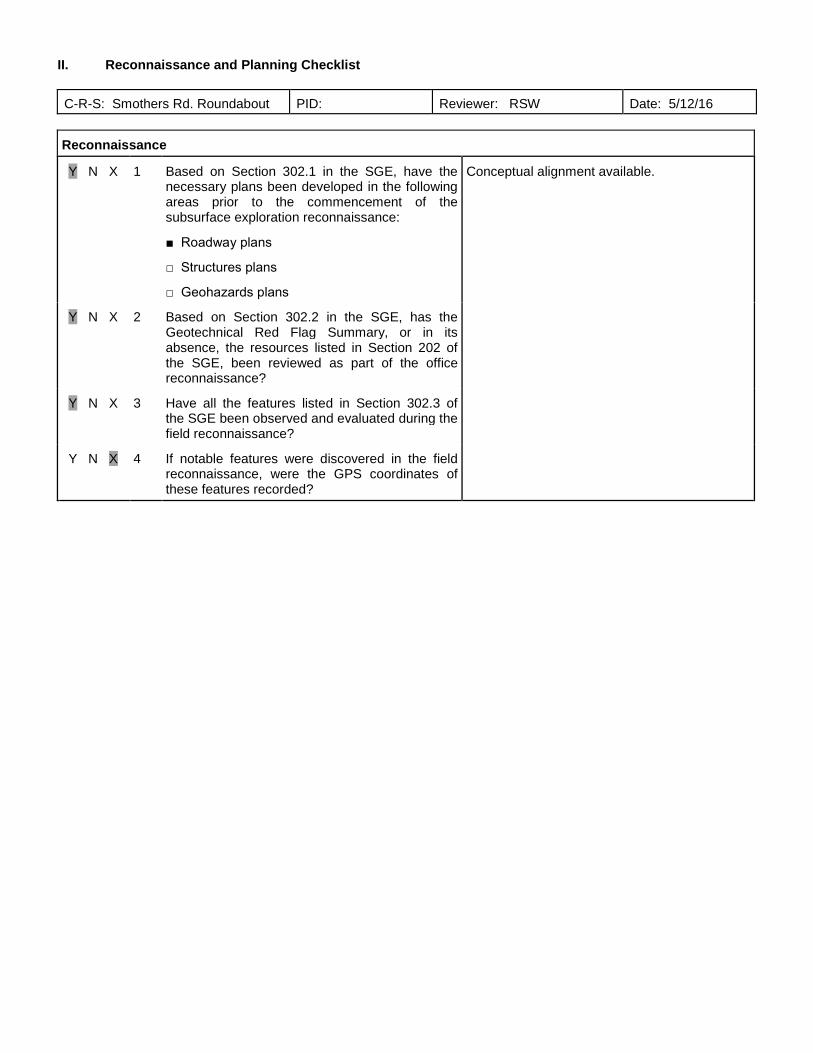
II. Reconnaissance and Planning Checklist
C-R-S: Smothers Rd. Roundabout PID: Reviewer: RSW Date: 5/12/16
Reconnaissance
Y N X 1 Based on Section 302.1 in the SGE, have thenecessary plans been developed in the followingareas prior to the commencement of thesubsurface exploration reconnaissance:
■ Roadway plans
□ Structures plans
□ Geohazards plans
Conceptual alignment available.
Y N X 2 Based on Section 302.2 in the SGE, has theGeotechnical Red Flag Summary, or in itsabsence, the resources listed in Section 202 ofthe SGE, been reviewed as part of the officereconnaissance?
Y N X 3 Have all the features listed in Section 302.3 ofthe SGE been observed and evaluated during thefield reconnaissance?
Y N X 4 If notable features were discovered in the fieldreconnaissance, were the GPS coordinates ofthese features recorded?
rweigand
Text Box
PLATE 13
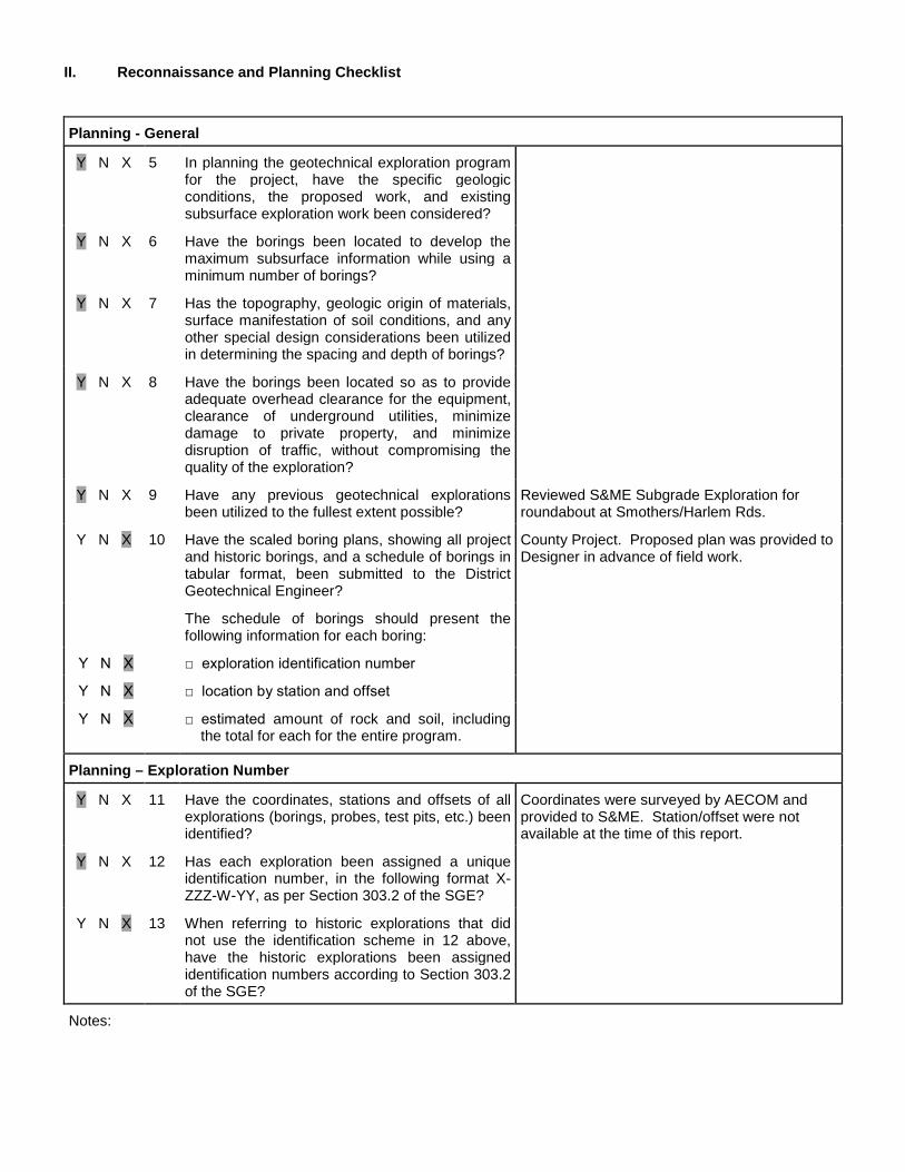
II. Reconnaissance and Planning Checklist
Planning - General
Y N X 5 In planning the geotechnical exploration programfor the project, have the specific geologicconditions, the proposed work, and existingsubsurface exploration work been considered?
Y N X 6 Have the borings been located to develop themaximum subsurface information while using aminimum number of borings?
Y N X 7 Has the topography, geologic origin of materials,surface manifestation of soil conditions, and anyother special design considerations been utilizedin determining the spacing and depth of borings?
Y N X 8 Have the borings been located so as to provideadequate overhead clearance for the equipment,clearance of underground utilities, minimizedamage to private property, and minimizedisruption of traffic, without compromising thequality of the exploration?
Y N X 9 Have any previous geotechnical explorationsbeen utilized to the fullest extent possible?
Reviewed S&ME Subgrade Exploration forroundabout at Smothers/Harlem Rds.
Y N X 10 Have the scaled boring plans, showing all projectand historic borings, and a schedule of borings intabular format, been submitted to the DistrictGeotechnical Engineer?
County Project. Proposed plan was provided toDesigner in advance of field work.
The schedule of borings should present thefollowing information for each boring:
Y N X □ exploration identification number
Y N X □ location by station and offset
Y N X □ estimated amount of rock and soil, includingthe total for each for the entire program.
Planning – Exploration Number
Y N X 11 Have the coordinates, stations and offsets of allexplorations (borings, probes, test pits, etc.) beenidentified?
Coordinates were surveyed by AECOM andprovided to S&ME. Station/offset were notavailable at the time of this report.
Y N X 12 Has each exploration been assigned a uniqueidentification number, in the following format X-ZZZ-W-YY, as per Section 303.2 of the SGE?
Y N X 13 When referring to historic explorations that didnot use the identification scheme in 12 above,have the historic explorations been assignedidentification numbers according to Section 303.2of the SGE?
Notes:
rweigand
Text Box
PLATE 14

II. Reconnaissance and Planning Checklist
Planning – Boring Types
Y N X 14 Based on Sections 303.3 to 303.76 of the SGE,have the location, depth, and samplingrequirements for the following boring types beendetermined for the project?
Check all boring types utilized for this project:
■ Existing Subgrades (Type A)
■ Roadway Borings (Type B)
□ Embankment Foundations (Type B1)
□ Cut Sections (Type B2)
□ Sidehill Cut Sections (Type B3)
□ Sidehill Cut-Fill Sections (Type B4)
□ Sidehill Fill Sections on Unstable Slopes (TypeB5)
□ Geohazard Borings (Type C)
□ Lakes, Ponds, and Low-Lying Areas (Type C1)
□ Peat Deposits, Compressible Soils, and LowStrength Soils (Type C2)
□ Uncontrolled Fills, Waste Pits, and ReclaimedSurface Mines (Type C3)
□ Underground Mines (C4)
□ Landslides (Type C5)
□ Karst (Type C6)
□ Proposed Underground Utilities (Type D)
□ Structure Borings (Type E)
□ Bridges (Type E1)
□ Culverts (Type E2 a,b,c)
□ Retaining Walls (Type E3 a,b,c)
□ Noise Barrier (Type E4)
□ High Mast Lighting Towers (Type E5)
□ Buildings and Salt Domes (Type E6)
Notes:
rweigand
Text Box
PLATE 15

III.C. Subgrade Checklist
C-R-S: Smothers Rd. Roundabout PID: Reviewer: RSW Date: 5/12/16
If you do not have any subgrade work on the project, you do not have to fill out this checklist.
Y N X 1 Has the subsurface investigation adequatelycharacterized the soil or rock according toGeotechnical Bulletin 1: Plan Subgrades (GB1)?
Y N X 2 If soils classified as A-2-5, A-4b, A-5, A-7-5, A-8a,or A-8b, or having a LL>65, are present at theproposed subgrade (soil profile), do the plansspecify that these materials need to be removedand replaced or chemically stabilized?
Y N X a If these materials are to be removed andreplaced, have the station limits, depth, andlateral limits for the planned removal beenprovided?
Removal should occur as part of recommendedglobal subgrade remediation program.
Y N X 3 If there is any rock, shale, or coal present at theproposed subgrade (CMS 204.05), do the plansspecify the removal of the material?
By others. See Section 5.3.2 of SubgradeExploration Report.
Y N X a If removal of any rock, shale, or coal isrequired, have the station limits, depth, andlateral limits for the planned removal of thematerial at proposed subgrade beenprovided?
Rock not encountered within 2 feet of theestimated subgrade level.
Y N X 4 In accordance with GB1, do the SPT values andexisting moisture contents for the proposedsubgrade soils indicate the need for subgradestabilization?
Y N X a If removal and replacement is applicable, hasthe detail of subgrade removal been shown onthe plans, including depth of removal, stationlimits, lateral extent, replacement material,and plan notes (Item 204 – SubgradeCompaction and Proof Rolling)?
By others.
Y N X b If chemical stabilization is applicable, has thedetail of this treatment been shown on theplans, including depth, percentage ofchemical, station limits, lateral extent, andplan notes?
Indicate type of subgrade treatment specified:
□ cement treatment □ lime treatment
□ lime kiln dust □ other
Y N X 5 If drainage or groundwater is an issue with theproposed subgrade, has an appropriate drainagesystem (e.g., pipe, underdrains) been provided?
By others.
Y N X 6 Has an appropriate quantity of Proof Rolling beenincluded in the plans (CMS 204.06)?
By others.
Y N X 7 Has a design CBR value been provided? Section 5.2
rweigand
Text Box
PLATE 16

III.C. Subgrade Checklist
Notes:
Stage 1:
rweigand
Text Box
PLATE 17