10 transport and storage of fluids
163
-
Upload
nguyennha1211 -
Category
Education
-
view
690 -
download
4
description
Transcript of 10 transport and storage of fluids

Copyright © 2008, 1997, 1984, 1973, 1963, 1950, 1941, 1934 by The McGraw-Hill Companies, Inc. All rights reserved. Manufactured in the UnitedStates of America. Except as permitted under the United States Copyright Act of 1976, no part of this publication may be reproduced or distributedin any form or by any means, or stored in a database or retrieval system, without the prior written permission of the publisher.
0-07-154217-5
The material in this eBook also appears in the print version of this title: 0-07-151133-4.
All trademarks are trademarks of their respective owners. Rather than put a trademark symbol after every occurrence of a trademarked name, we usenames in an editorial fashion only, and to the benefit of the trademark owner, with no intention of infringement of the trademark. Where such designations appear in this book, they have been printed with initial caps.
McGraw-Hill eBooks are available at special quantity discounts to use as premiums and sales promotions, or for use in corporate training programs.For more information, please contact George Hoare, Special Sales, at [email protected] or (212) 904-4069.
TERMS OF USE
This is a copyrighted work and The McGraw-Hill Companies, Inc. (“McGraw-Hill”) and its licensors reserve all rights in and to the work. Use of thiswork is subject to these terms. Except as permitted under the Copyright Act of 1976 and the right to store and retrieve one copy of the work, you maynot decompile, disassemble, reverse engineer, reproduce, modify, create derivative works based upon, transmit, distribute, disseminate, sell, publishor sublicense the work or any part of it without McGraw-Hill’s prior consent. You may use the work for your own noncommercial and personal use;any other use of the work is strictly prohibited. Your right to use the work may be terminated if you fail to comply with these terms.
THE WORK IS PROVIDED “AS IS.” McGRAW-HILL AND ITS LICENSORS MAKE NO GUARANTEES OR WARRANTIES AS TO THEACCURACY, ADEQUACY OR COMPLETENESS OF OR RESULTS TO BE OBTAINED FROM USING THE WORK, INCLUDING ANYINFORMATION THAT CAN BE ACCESSED THROUGH THE WORK VIA HYPERLINK OR OTHERWISE, AND EXPRESSLY DISCLAIMANY WARRANTY, EXPRESS OR IMPLIED, INCLUDING BUT NOT LIMITED TO IMPLIED WARRANTIES OF MERCHANTABILITY ORFITNESS FOR A PARTICULAR PURPOSE. McGraw-Hill and its licensors do not warrant or guarantee that the functions contained in the work willmeet your requirements or that its operation will be uninterrupted or error free. Neither McGraw-Hill nor its licensors shall be liable to you or anyone else for any inaccuracy, error or omission, regardless of cause, in the work or for any damages resulting therefrom. McGraw-Hill has noresponsibility for the content of any information accessed through the work. Under no circumstances shall McGraw-Hill and/or its licensors be liablefor any indirect, incidental, special, punitive, consequential or similar damages that result from the use of or inability to use the work, even if any ofthem has been advised of the possibility of such damages. This limitation of liability shall apply to any claim or cause whatsoever whether such claimor cause arises in contract, tort or otherwise.
DOI: 10.1036/0071511334

This page intentionally left blank
MEASUREMENT OF FLOWIntroduction . . . . . . . . . . . . . . . . . . . . . . . . . . . . . . . . . . . . . . . . . . . . . . . 10-6Properties and Behavior of Fluids . . . . . . . . . . . . . . . . . . . . . . . . . . . . . . 10-6Total Temperature . . . . . . . . . . . . . . . . . . . . . . . . . . . . . . . . . . . . . . . . . . 10-7
Thermocouples . . . . . . . . . . . . . . . . . . . . . . . . . . . . . . . . . . . . . . . . . . . 10-7Resistive Thermal Detectors (RTDs) . . . . . . . . . . . . . . . . . . . . . . . . . 10-7
Static Temperature . . . . . . . . . . . . . . . . . . . . . . . . . . . . . . . . . . . . . . . . . . 10-7Dry- and Wet-Bulb Temperatures . . . . . . . . . . . . . . . . . . . . . . . . . . . . . . 10-7Pressure Measurements . . . . . . . . . . . . . . . . . . . . . . . . . . . . . . . . . . . . . . 10-7
Liquid-Column Manometers . . . . . . . . . . . . . . . . . . . . . . . . . . . . . . . . 10-8
Tube Size for Manometers . . . . . . . . . . . . . . . . . . . . . . . . . . . . . . . . . . 10-8Multiplying Gauges. . . . . . . . . . . . . . . . . . . . . . . . . . . . . . . . . . . . . . . . 10-8Mechanical Pressure Gauges . . . . . . . . . . . . . . . . . . . . . . . . . . . . . . . . 10-9Conditions of Use . . . . . . . . . . . . . . . . . . . . . . . . . . . . . . . . . . . . . . . . . 10-9Calibration of Gauges . . . . . . . . . . . . . . . . . . . . . . . . . . . . . . . . . . . . . . 10-9
Static Pressure. . . . . . . . . . . . . . . . . . . . . . . . . . . . . . . . . . . . . . . . . . . . . . 10-10Local Static Pressure . . . . . . . . . . . . . . . . . . . . . . . . . . . . . . . . . . . . . . 10-10Average Static Pressure . . . . . . . . . . . . . . . . . . . . . . . . . . . . . . . . . . . . 10-10Specifications for Piezometer Taps . . . . . . . . . . . . . . . . . . . . . . . . . . . 10-10
Velocity Measurements . . . . . . . . . . . . . . . . . . . . . . . . . . . . . . . . . . . . . . 10-11
10-1
Section 10
Transport and Storage of Fluids
Meherwan P. Boyce, Ph.D., P.E. Chairman and Principal Consultant, The Boyce Con-sultancy Group, LLC; Fellow, American Society of Mechanical Engineers; Registered Profes-sional Engineer (Texas) (Section Editor, Measurement of Flow, Pumps and Compressors)
Victor H. Edwards, Ph.D., P.E. Process Director, Aker Kvaerner, Inc.; Fellow, AmericanInstitute of Chemical Engineers; Member, American Association for the Advancement of Science,American Chemical Society, National Society of Professional Engineers; Life Member, New YorkAcademy of Sciences; Registered Professional Engineer (Texas) (Section Editor, Measurement of Flow)
Terry W. Cowley, B.S., M.A. Consultant, DuPont Engineering; Member, American Soci-ety of Mechanical Engineers, American Welding Society, National Association of CorrosionEngineers (Polymeric Materials)
Timothy Fan, P.E., M.Sc. Chief Project Engineer, Foster Wheeler USA; Member, AmericanSociety of Mechanical Engineers, Registered Professional Engineer (Massachusetts and Texas)(Piping)
Hugh D. Kaiser, P.E., B.S., MBA Principal Engineer, PB Energy Storage Services, Inc.;Senior Member, American Institute of Chemical Engineers; Registered Professional Engineer(Texas) (Underground Storage of Liquids and Gases, Cost of Storage Facilities, Bulk Transportof Fluids)
Wayne B. Geyer, P.E. Executive Vice President, Steel Tank Institute and Steel Plate Fab-ricators Association; Registered Professional Engineer (Atmospheric Tanks)
David Nadel, P.E., M.S. Senior Principal Mechanical Engineer, Aker Kvaerner, Inc.;Registered Professional Engineer (Pressure Vessels)
Larry Skoda, P.E. Principal Piping Engineer, Aker Kvaerner, Inc.; Registered ProfessionalEngineer (Texas) (Piping)
Shawn Testone Product Manager, De Dietrich Process Systems (Glass Piping and Glass-Lined Piping)
Kenneth L. Walter, Ph.D. Process Manager—Technology, Aker Kvaerner, Inc.; SeniorMember, American Institute of Chemical Engineers, Sigma Xi, Tau Beta Pi (Storage and ProcessVessels)
Copyright © 2008, 1997, 1984, 1973, 1963, 1950, 1941, 1934 by The McGraw-Hill Companies, Inc. Click here for terms of use.
Variables Affecting Measurement . . . . . . . . . . . . . . . . . . . . . . . . . . . . 10-11Velocity Profile Effects . . . . . . . . . . . . . . . . . . . . . . . . . . . . . . . . . . . . . 10-11Other Flow Disturbances . . . . . . . . . . . . . . . . . . . . . . . . . . . . . . . . . . . 10-11Pitot Tubes . . . . . . . . . . . . . . . . . . . . . . . . . . . . . . . . . . . . . . . . . . . . . . 10-11Special Tubes . . . . . . . . . . . . . . . . . . . . . . . . . . . . . . . . . . . . . . . . . . . . 10-13Traversing for Mean Velocity . . . . . . . . . . . . . . . . . . . . . . . . . . . . . . . . 10-13
Flowmeters . . . . . . . . . . . . . . . . . . . . . . . . . . . . . . . . . . . . . . . . . . . . . . . . 10-14Industry Guidelines and Standards . . . . . . . . . . . . . . . . . . . . . . . . . . . . . 10-14Classification of Flowmeters . . . . . . . . . . . . . . . . . . . . . . . . . . . . . . . . . . 10-14
Differential Pressure Meters . . . . . . . . . . . . . . . . . . . . . . . . . . . . . . . . 10-14Velocity Meters . . . . . . . . . . . . . . . . . . . . . . . . . . . . . . . . . . . . . . . . . . . 10-14Mass Meters . . . . . . . . . . . . . . . . . . . . . . . . . . . . . . . . . . . . . . . . . . . . . 10-14Volumetric Meters . . . . . . . . . . . . . . . . . . . . . . . . . . . . . . . . . . . . . . . . 10-14Variable-Area Meters . . . . . . . . . . . . . . . . . . . . . . . . . . . . . . . . . . . . . . 10-14Open-Channel Flow Measurement . . . . . . . . . . . . . . . . . . . . . . . . . . . 10-14
Differential Pressure Flowmeters . . . . . . . . . . . . . . . . . . . . . . . . . . . . . . 10-15General Principles . . . . . . . . . . . . . . . . . . . . . . . . . . . . . . . . . . . . . . . . 10-15Orifice Meters. . . . . . . . . . . . . . . . . . . . . . . . . . . . . . . . . . . . . . . . . . . . 10-16Venturi Meters . . . . . . . . . . . . . . . . . . . . . . . . . . . . . . . . . . . . . . . . . . . 10-18Flow Nozzles. . . . . . . . . . . . . . . . . . . . . . . . . . . . . . . . . . . . . . . . . . . . . 10-19Critical Flow Nozzle . . . . . . . . . . . . . . . . . . . . . . . . . . . . . . . . . . . . . . . 10-19Elbow Meters . . . . . . . . . . . . . . . . . . . . . . . . . . . . . . . . . . . . . . . . . . . . 10-20Accuracy . . . . . . . . . . . . . . . . . . . . . . . . . . . . . . . . . . . . . . . . . . . . . . . . 10-20
Velocity Meters . . . . . . . . . . . . . . . . . . . . . . . . . . . . . . . . . . . . . . . . . . . . . 10-21Anemometers . . . . . . . . . . . . . . . . . . . . . . . . . . . . . . . . . . . . . . . . . . . . 10-21Turbine Flowmeters . . . . . . . . . . . . . . . . . . . . . . . . . . . . . . . . . . . . . . . 10-21
Mass Flowmeters . . . . . . . . . . . . . . . . . . . . . . . . . . . . . . . . . . . . . . . . . . . 10-21General Principles . . . . . . . . . . . . . . . . . . . . . . . . . . . . . . . . . . . . . . . . 10-21Axial-Flow Transverse-Momentum Mass Flowmeter . . . . . . . . . . . . . . . . . . . . . . . . . . . . . . . . . . . . . . . . . 10-21
Inferential Mass Flowmeter. . . . . . . . . . . . . . . . . . . . . . . . . . . . . . . . . 10-21Coriolis Mass Flowmeter . . . . . . . . . . . . . . . . . . . . . . . . . . . . . . . . . . . 10-22
Variable-Area Meters . . . . . . . . . . . . . . . . . . . . . . . . . . . . . . . . . . . . . . . . 10-22General Principles . . . . . . . . . . . . . . . . . . . . . . . . . . . . . . . . . . . . . . . . 10-22Rotameters . . . . . . . . . . . . . . . . . . . . . . . . . . . . . . . . . . . . . . . . . . . . . . 10-22
Two-Phase Systems. . . . . . . . . . . . . . . . . . . . . . . . . . . . . . . . . . . . . . . . . . 10-22Gas-Solid Mixtures . . . . . . . . . . . . . . . . . . . . . . . . . . . . . . . . . . . . . . . . 10-23Gas-Liquid Mixtures. . . . . . . . . . . . . . . . . . . . . . . . . . . . . . . . . . . . . . . 10-23Liquid-Solid Mixtures. . . . . . . . . . . . . . . . . . . . . . . . . . . . . . . . . . . . . . 10-23
Flowmeter Selection. . . . . . . . . . . . . . . . . . . . . . . . . . . . . . . . . . . . . . . . . 10-23Weirs . . . . . . . . . . . . . . . . . . . . . . . . . . . . . . . . . . . . . . . . . . . . . . . . . . . . . 10-23
PUMPS AND COMPRESSORSIntroduction . . . . . . . . . . . . . . . . . . . . . . . . . . . . . . . . . . . . . . . . . . . . . . . 10-24Terminology . . . . . . . . . . . . . . . . . . . . . . . . . . . . . . . . . . . . . . . . . . . . . . . 10-25
Displacement . . . . . . . . . . . . . . . . . . . . . . . . . . . . . . . . . . . . . . . . . . . . 10-25Centrifugal Force . . . . . . . . . . . . . . . . . . . . . . . . . . . . . . . . . . . . . . . . . 10-25Electromagnetic Force. . . . . . . . . . . . . . . . . . . . . . . . . . . . . . . . . . . . . 10-25Transfer of Momentum . . . . . . . . . . . . . . . . . . . . . . . . . . . . . . . . . . . . 10-25Mechanical Impulse . . . . . . . . . . . . . . . . . . . . . . . . . . . . . . . . . . . . . . . 10-25Measurement of Performance . . . . . . . . . . . . . . . . . . . . . . . . . . . . . . . 10-25Capacity. . . . . . . . . . . . . . . . . . . . . . . . . . . . . . . . . . . . . . . . . . . . . . . . . 10-25Total Dynamic Head. . . . . . . . . . . . . . . . . . . . . . . . . . . . . . . . . . . . . . . 10-25Total Suction Head . . . . . . . . . . . . . . . . . . . . . . . . . . . . . . . . . . . . . . . . 10-25Static Suction Head . . . . . . . . . . . . . . . . . . . . . . . . . . . . . . . . . . . . . . . 10-26Total Discharge Head. . . . . . . . . . . . . . . . . . . . . . . . . . . . . . . . . . . . . . 10-26Static Discharge Head . . . . . . . . . . . . . . . . . . . . . . . . . . . . . . . . . . . . . 10-26Velocity . . . . . . . . . . . . . . . . . . . . . . . . . . . . . . . . . . . . . . . . . . . . . . . . . 10-27Velocity Head . . . . . . . . . . . . . . . . . . . . . . . . . . . . . . . . . . . . . . . . . . . . 10-27Viscosity. . . . . . . . . . . . . . . . . . . . . . . . . . . . . . . . . . . . . . . . . . . . . . . . . 10-27Friction Head . . . . . . . . . . . . . . . . . . . . . . . . . . . . . . . . . . . . . . . . . . . . 10-27Work Performed in Pumping . . . . . . . . . . . . . . . . . . . . . . . . . . . . . . . . 10-27
Pump Selection. . . . . . . . . . . . . . . . . . . . . . . . . . . . . . . . . . . . . . . . . . . . . 10-27Range of Operation . . . . . . . . . . . . . . . . . . . . . . . . . . . . . . . . . . . . . . . 10-27
Net Positive Suction Head . . . . . . . . . . . . . . . . . . . . . . . . . . . . . . . . . . . . 10-27Suction Limitations of a Pump. . . . . . . . . . . . . . . . . . . . . . . . . . . . . . . 10-27NPSH Requirements for Other Liquids . . . . . . . . . . . . . . . . . . . . . . . 10-28Example 1: NPSH Calculation. . . . . . . . . . . . . . . . . . . . . . . . . . . . . . . 10-28
Pump Specifications . . . . . . . . . . . . . . . . . . . . . . . . . . . . . . . . . . . . . . . . . 10-28Positive-Displacement Pumps . . . . . . . . . . . . . . . . . . . . . . . . . . . . . . . . . 10-28
Reciprocating Pumps . . . . . . . . . . . . . . . . . . . . . . . . . . . . . . . . . . . . . . 10-28Piston Pumps . . . . . . . . . . . . . . . . . . . . . . . . . . . . . . . . . . . . . . . . . . . . 10-30Diaphragm Pumps . . . . . . . . . . . . . . . . . . . . . . . . . . . . . . . . . . . . . . . . 10-30Rotary Pumps . . . . . . . . . . . . . . . . . . . . . . . . . . . . . . . . . . . . . . . . . . . . 10-31Gear Pumps . . . . . . . . . . . . . . . . . . . . . . . . . . . . . . . . . . . . . . . . . . . . . 10-31Screw Pumps. . . . . . . . . . . . . . . . . . . . . . . . . . . . . . . . . . . . . . . . . . . . . 10-32Fluid-Displacement Pumps . . . . . . . . . . . . . . . . . . . . . . . . . . . . . . . . . 10-32
Centrifugal Pumps . . . . . . . . . . . . . . . . . . . . . . . . . . . . . . . . . . . . . . . . . . 10-32Casings . . . . . . . . . . . . . . . . . . . . . . . . . . . . . . . . . . . . . . . . . . . . . . . . . 10-33Action of a Centrifugal Pump . . . . . . . . . . . . . . . . . . . . . . . . . . . . . . . 10-33
Centrifugal Pump Characteristics . . . . . . . . . . . . . . . . . . . . . . . . . . . . 10-33System Curves. . . . . . . . . . . . . . . . . . . . . . . . . . . . . . . . . . . . . . . . . . . . 10-34Pump Selection. . . . . . . . . . . . . . . . . . . . . . . . . . . . . . . . . . . . . . . . . . . 10-34Process Pumps . . . . . . . . . . . . . . . . . . . . . . . . . . . . . . . . . . . . . . . . . . . 10-34Sealing the Centrifugal Chemical Pump . . . . . . . . . . . . . . . . . . . . . . . 10-35Double-Suction Single-Stage Pumps. . . . . . . . . . . . . . . . . . . . . . . . . . 10-35Close-Coupled Pumps . . . . . . . . . . . . . . . . . . . . . . . . . . . . . . . . . . . . . 10-35Canned-Motor Pumps . . . . . . . . . . . . . . . . . . . . . . . . . . . . . . . . . . . . . 10-36Vertical Pumps . . . . . . . . . . . . . . . . . . . . . . . . . . . . . . . . . . . . . . . . . . . 10-36Sump Pumps . . . . . . . . . . . . . . . . . . . . . . . . . . . . . . . . . . . . . . . . . . . . . 10-37Multistage Centrifugal Pumps . . . . . . . . . . . . . . . . . . . . . . . . . . . . . . . 10-37
Propeller and Turbine Pumps . . . . . . . . . . . . . . . . . . . . . . . . . . . . . . . . . 10-37Axial-Flow (Propeller) Pumps . . . . . . . . . . . . . . . . . . . . . . . . . . . . . . . 10-37Turbine Pumps . . . . . . . . . . . . . . . . . . . . . . . . . . . . . . . . . . . . . . . . . . . 10-38Regenerative Pumps. . . . . . . . . . . . . . . . . . . . . . . . . . . . . . . . . . . . . . . 10-38
Jet Pumps . . . . . . . . . . . . . . . . . . . . . . . . . . . . . . . . . . . . . . . . . . . . . . . . . 10-39Electromagnetic Pumps . . . . . . . . . . . . . . . . . . . . . . . . . . . . . . . . . . . . . . 10-39Pump Diagnostics . . . . . . . . . . . . . . . . . . . . . . . . . . . . . . . . . . . . . . . . . . . 10-40Compressors . . . . . . . . . . . . . . . . . . . . . . . . . . . . . . . . . . . . . . . . . . . . . . . 10-40
Compressor Selection. . . . . . . . . . . . . . . . . . . . . . . . . . . . . . . . . . . . . . 10-42Compression of Gases . . . . . . . . . . . . . . . . . . . . . . . . . . . . . . . . . . . . . . . 10-42
Theory of Compression . . . . . . . . . . . . . . . . . . . . . . . . . . . . . . . . . . . . 10-42Adiabatic Calculations . . . . . . . . . . . . . . . . . . . . . . . . . . . . . . . . . . . . . 10-44Reciprocating Compressors . . . . . . . . . . . . . . . . . . . . . . . . . . . . . . . . . 10-45
Fans and Blowers . . . . . . . . . . . . . . . . . . . . . . . . . . . . . . . . . . . . . . . . . . . 10-49Axial-Flow Fans . . . . . . . . . . . . . . . . . . . . . . . . . . . . . . . . . . . . . . . . . . 10-49Centrifugal Blowers . . . . . . . . . . . . . . . . . . . . . . . . . . . . . . . . . . . . . . . 10-49Forward-Curved Blade Blowers . . . . . . . . . . . . . . . . . . . . . . . . . . . . . 10-50Backward-Curved Blade Blowers . . . . . . . . . . . . . . . . . . . . . . . . . . . . 10-50Fan Performance . . . . . . . . . . . . . . . . . . . . . . . . . . . . . . . . . . . . . . . . . 10-52
Continuous-Flow Compressors . . . . . . . . . . . . . . . . . . . . . . . . . . . . . . . . 10-52Centrifugal Compressors . . . . . . . . . . . . . . . . . . . . . . . . . . . . . . . . . . . 10-52Compressor Configuration . . . . . . . . . . . . . . . . . . . . . . . . . . . . . . . . . . 10-53Impeller Fabrication. . . . . . . . . . . . . . . . . . . . . . . . . . . . . . . . . . . . . . . 10-54Axial-Flow Compressors. . . . . . . . . . . . . . . . . . . . . . . . . . . . . . . . . . . . 10-54Positive-Displacement Compressors . . . . . . . . . . . . . . . . . . . . . . . . . . 10-56Rotary Compressors . . . . . . . . . . . . . . . . . . . . . . . . . . . . . . . . . . . . . . . 10-56
Ejectors . . . . . . . . . . . . . . . . . . . . . . . . . . . . . . . . . . . . . . . . . . . . . . . . . . . 10-57Ejector Performance . . . . . . . . . . . . . . . . . . . . . . . . . . . . . . . . . . . . . . 10-57Uses of Ejectors . . . . . . . . . . . . . . . . . . . . . . . . . . . . . . . . . . . . . . . . . . 10-58
Vacuum Systems . . . . . . . . . . . . . . . . . . . . . . . . . . . . . . . . . . . . . . . . . . . . 10-58Vacuum Equipment . . . . . . . . . . . . . . . . . . . . . . . . . . . . . . . . . . . . . . . 10-58
Sealing of Rotating Shafts. . . . . . . . . . . . . . . . . . . . . . . . . . . . . . . . . . . . . 10-59Noncontact Seals . . . . . . . . . . . . . . . . . . . . . . . . . . . . . . . . . . . . . . . . . 10-59Labyrinth Seals . . . . . . . . . . . . . . . . . . . . . . . . . . . . . . . . . . . . . . . . . . . 10-59Ring Seals . . . . . . . . . . . . . . . . . . . . . . . . . . . . . . . . . . . . . . . . . . . . . . . 10-62Fixed Seal Rings . . . . . . . . . . . . . . . . . . . . . . . . . . . . . . . . . . . . . . . . . . 10-62Floating Seal Rings . . . . . . . . . . . . . . . . . . . . . . . . . . . . . . . . . . . . . . . . 10-62Packing Seal . . . . . . . . . . . . . . . . . . . . . . . . . . . . . . . . . . . . . . . . . . . . . 10-62Mechanical Face Seals . . . . . . . . . . . . . . . . . . . . . . . . . . . . . . . . . . . . . 10-63Mechanical Seal Selection . . . . . . . . . . . . . . . . . . . . . . . . . . . . . . . . . . 10-63Internal and External Seals . . . . . . . . . . . . . . . . . . . . . . . . . . . . . . . . . 10-64Throttle Bushings . . . . . . . . . . . . . . . . . . . . . . . . . . . . . . . . . . . . . . . . . 10-64Materials . . . . . . . . . . . . . . . . . . . . . . . . . . . . . . . . . . . . . . . . . . . . . . . . 10-65
Bearings. . . . . . . . . . . . . . . . . . . . . . . . . . . . . . . . . . . . . . . . . . . . . . . . . . . 10-65Types of Bearings . . . . . . . . . . . . . . . . . . . . . . . . . . . . . . . . . . . . . . . . . 10-65Thrust Bearings. . . . . . . . . . . . . . . . . . . . . . . . . . . . . . . . . . . . . . . . . . . 10-66Thrust-Bearing Power Loss . . . . . . . . . . . . . . . . . . . . . . . . . . . . . . . . . 10-67
Centrifugal Compressor Problems. . . . . . . . . . . . . . . . . . . . . . . . . . . . . . 10-67Compressor Fouling . . . . . . . . . . . . . . . . . . . . . . . . . . . . . . . . . . . . . . . 10-68Compressor Failures. . . . . . . . . . . . . . . . . . . . . . . . . . . . . . . . . . . . . . . 10-69Impeller Problems . . . . . . . . . . . . . . . . . . . . . . . . . . . . . . . . . . . . . . . . 10-69Rotor Thrust Problems. . . . . . . . . . . . . . . . . . . . . . . . . . . . . . . . . . . . . 10-69Journal Bearing Failures. . . . . . . . . . . . . . . . . . . . . . . . . . . . . . . . . . . . 10-70Thrust Bearing Failures . . . . . . . . . . . . . . . . . . . . . . . . . . . . . . . . . . . . 10-70Compressor Seal Problems . . . . . . . . . . . . . . . . . . . . . . . . . . . . . . . . . 10-70
Rotor Dynamics . . . . . . . . . . . . . . . . . . . . . . . . . . . . . . . . . . . . . . . . . . . . 10-70Vibration Monitoring . . . . . . . . . . . . . . . . . . . . . . . . . . . . . . . . . . . . . . . . 10-71
Example 2: Vibration . . . . . . . . . . . . . . . . . . . . . . . . . . . . . . . . . . . . . . 10-72
PROCESS PLANT PIPINGIntroduction . . . . . . . . . . . . . . . . . . . . . . . . . . . . . . . . . . . . . . . . . . . . . . . 10-73Codes and Standards . . . . . . . . . . . . . . . . . . . . . . . . . . . . . . . . . . . . . . . . 10-73
Units: Pipe and Tubing Sizes and Ratings . . . . . . . . . . . . . . . . . . . . . . 10-73Pressure-Piping Codes . . . . . . . . . . . . . . . . . . . . . . . . . . . . . . . . . . . . . 10-73National Standards . . . . . . . . . . . . . . . . . . . . . . . . . . . . . . . . . . . . . . . . 10-73Government Regulations: OSHA. . . . . . . . . . . . . . . . . . . . . . . . . . . . . 10-73International Regulations . . . . . . . . . . . . . . . . . . . . . . . . . . . . . . . . . . . 10-74
Code Contents and Scope . . . . . . . . . . . . . . . . . . . . . . . . . . . . . . . . . . . . 10-74Selection of Pipe System Materials . . . . . . . . . . . . . . . . . . . . . . . . . . . . . 10-74
10-2 TRANSPORT AND STORAGE OF FLUIDS

General Considerations . . . . . . . . . . . . . . . . . . . . . . . . . . . . . . . . . . . . 10-74Specific Material Considerations—Metals . . . . . . . . . . . . . . . . . . . . . 10-75Specific Material Considerations—Nonmetals . . . . . . . . . . . . . . . . . . 10-76
Metallic Piping System Components. . . . . . . . . . . . . . . . . . . . . . . . . . . . 10-76Seamless Pipe and Tubing . . . . . . . . . . . . . . . . . . . . . . . . . . . . . . . . . . 10-76Welded Pipe and Tubing . . . . . . . . . . . . . . . . . . . . . . . . . . . . . . . . . . . 10-76Tubing . . . . . . . . . . . . . . . . . . . . . . . . . . . . . . . . . . . . . . . . . . . . . . . . . . 10-77Methods of Joining Pipe. . . . . . . . . . . . . . . . . . . . . . . . . . . . . . . . . . . . 10-77Flanged Joints . . . . . . . . . . . . . . . . . . . . . . . . . . . . . . . . . . . . . . . . . . . . 10-81Ring Joint Flanges . . . . . . . . . . . . . . . . . . . . . . . . . . . . . . . . . . . . . . . . 10-85Bolting . . . . . . . . . . . . . . . . . . . . . . . . . . . . . . . . . . . . . . . . . . . . . . . . . . 10-85Miscellaneous Mechanical Joints . . . . . . . . . . . . . . . . . . . . . . . . . . . . . 10-87Pipe Fittings and Bends . . . . . . . . . . . . . . . . . . . . . . . . . . . . . . . . . . . . 10-89Valves. . . . . . . . . . . . . . . . . . . . . . . . . . . . . . . . . . . . . . . . . . . . . . . . . . . 10-93
Cast Iron, Ductile Iron, and High-Silicon Iron Piping Systems. . . . . . . 10-98Cast Iron and Ductile Iron. . . . . . . . . . . . . . . . . . . . . . . . . . . . . . . . . . 10-98High-Silicon Iron . . . . . . . . . . . . . . . . . . . . . . . . . . . . . . . . . . . . . . . . . 10-99
Nonferrous Metal Piping Systems . . . . . . . . . . . . . . . . . . . . . . . . . . . . . . 10-99Aluminum . . . . . . . . . . . . . . . . . . . . . . . . . . . . . . . . . . . . . . . . . . . . . . . 10-99Copper and Copper Alloys . . . . . . . . . . . . . . . . . . . . . . . . . . . . . . . . . . 10-100Nickel and Nickel Alloys . . . . . . . . . . . . . . . . . . . . . . . . . . . . . . . . . . . 10-100Titanium . . . . . . . . . . . . . . . . . . . . . . . . . . . . . . . . . . . . . . . . . . . . . . . . 10-101Flexible Metal Hose . . . . . . . . . . . . . . . . . . . . . . . . . . . . . . . . . . . . . . . 10-101
Nonmetallic Pipe and Metallic Piping Systems with Nonmetallic Linings . . . . . . . . . . . . . . . . . . . . . . . . . . . . . . . . . . . . . . . 10-103Cement-Lined Carbon-Steel Pipe . . . . . . . . . . . . . . . . . . . . . . . . . . . . 10-103Concrete Pipe . . . . . . . . . . . . . . . . . . . . . . . . . . . . . . . . . . . . . . . . . . . . 10-104Glass Pipe and Fittings . . . . . . . . . . . . . . . . . . . . . . . . . . . . . . . . . . . . . 10-104Glass-Lined Steel Pipe and Fittings. . . . . . . . . . . . . . . . . . . . . . . . . . . 10-105Fused Silica or Fused Quartz. . . . . . . . . . . . . . . . . . . . . . . . . . . . . . . . 10-105Plastic-Lined Steel Pipe . . . . . . . . . . . . . . . . . . . . . . . . . . . . . . . . . . . . 10-105Rubber-Lined Steel Pipe . . . . . . . . . . . . . . . . . . . . . . . . . . . . . . . . . . . 10-106Plastic Pipe . . . . . . . . . . . . . . . . . . . . . . . . . . . . . . . . . . . . . . . . . . . . . . 10-106Reinforced-Thermosetting-Resin (RTR) Pipe . . . . . . . . . . . . . . . . . . 10-107
Design of Piping Systems . . . . . . . . . . . . . . . . . . . . . . . . . . . . . . . . . . . . . 10-107Safeguarding . . . . . . . . . . . . . . . . . . . . . . . . . . . . . . . . . . . . . . . . . . . . . 10-107Classification of Fluid Services . . . . . . . . . . . . . . . . . . . . . . . . . . . . . . 10-107Category D . . . . . . . . . . . . . . . . . . . . . . . . . . . . . . . . . . . . . . . . . . . . . . 10-107Category M . . . . . . . . . . . . . . . . . . . . . . . . . . . . . . . . . . . . . . . . . . . . . . 10-107Design Conditions . . . . . . . . . . . . . . . . . . . . . . . . . . . . . . . . . . . . . . . . 10-107Effects of Support, Anchor, and Terminal Movements . . . . . . . . . . . 10-108Reduced Ductility. . . . . . . . . . . . . . . . . . . . . . . . . . . . . . . . . . . . . . . . . 10-108Cyclic Effects . . . . . . . . . . . . . . . . . . . . . . . . . . . . . . . . . . . . . . . . . . . . 10-108Air Condensation Effects . . . . . . . . . . . . . . . . . . . . . . . . . . . . . . . . . . . 10-108Design Criteria: Metallic Pipe . . . . . . . . . . . . . . . . . . . . . . . . . . . . . . . 10-108Limits of Calculated Stresses due to Sustained Loadsand Displacement Strains. . . . . . . . . . . . . . . . . . . . . . . . . . . . . . . . . . 10-111
Pressure Design of Metallic Components . . . . . . . . . . . . . . . . . . . . . . 10-111Test Conditions . . . . . . . . . . . . . . . . . . . . . . . . . . . . . . . . . . . . . . . . . . . 10-113Thermal Expansion and Flexibility: Metallic Piping . . . . . . . . . . . . . . 10-114Reactions: Metallic Piping . . . . . . . . . . . . . . . . . . . . . . . . . . . . . . . . . . 10-120Pipe Supports . . . . . . . . . . . . . . . . . . . . . . . . . . . . . . . . . . . . . . . . . . . . 10-122Design Criteria: Nonmetallic Pipe. . . . . . . . . . . . . . . . . . . . . . . . . . . . 10-123
Fabrication, Assembly, and Erection . . . . . . . . . . . . . . . . . . . . . . . . . . . . 10-123Welding, Brazing, or Soldering . . . . . . . . . . . . . . . . . . . . . . . . . . . . . . 10-123
Bending and Forming. . . . . . . . . . . . . . . . . . . . . . . . . . . . . . . . . . . . . . 10-126Preheating and Heat Treatment. . . . . . . . . . . . . . . . . . . . . . . . . . . . . . 10-126Joining Nonmetallic Pipe . . . . . . . . . . . . . . . . . . . . . . . . . . . . . . . . . . . 10-126Assembly and Erection. . . . . . . . . . . . . . . . . . . . . . . . . . . . . . . . . . . . . 10-126
Examination, Inspection, and Testing . . . . . . . . . . . . . . . . . . . . . . . . . . . 10-126Examination and Inspection. . . . . . . . . . . . . . . . . . . . . . . . . . . . . . . . . 10-126Examination Methods . . . . . . . . . . . . . . . . . . . . . . . . . . . . . . . . . . . . . . 10-128Type and Extent of Required Examination . . . . . . . . . . . . . . . . . . . . . 10-131Impact Testing . . . . . . . . . . . . . . . . . . . . . . . . . . . . . . . . . . . . . . . . . . . 10-133Pressure Testing . . . . . . . . . . . . . . . . . . . . . . . . . . . . . . . . . . . . . . . . . . 10-133
Cost Comparison of Piping Systems . . . . . . . . . . . . . . . . . . . . . . . . . . . . 10-135Forces of Piping on Process Machinery and Piping Vibration . . . . . . . . 10-135Heat Tracing of Piping Systems . . . . . . . . . . . . . . . . . . . . . . . . . . . . . . . . 10-135
Types of Heat-Tracing Systems . . . . . . . . . . . . . . . . . . . . . . . . . . . . . . 10-137Choosing the Best Tracing System. . . . . . . . . . . . . . . . . . . . . . . . . . . . 10-140
STORAGE AND PROCESS VESSELSStorage of Liquids. . . . . . . . . . . . . . . . . . . . . . . . . . . . . . . . . . . . . . . . . . . 10-140
Atmospheric Tanks . . . . . . . . . . . . . . . . . . . . . . . . . . . . . . . . . . . . . . . . 10-140Shop-Fabricated Storage Tanks . . . . . . . . . . . . . . . . . . . . . . . . . . . . . . 10-140USTs versus ASTs . . . . . . . . . . . . . . . . . . . . . . . . . . . . . . . . . . . . . . . . . 10-140Aboveground Storage Tanks. . . . . . . . . . . . . . . . . . . . . . . . . . . . . . . . . 10-140Pressure Tanks . . . . . . . . . . . . . . . . . . . . . . . . . . . . . . . . . . . . . . . . . . . 10-144Calculation of Tank Volume . . . . . . . . . . . . . . . . . . . . . . . . . . . . . . . . . 10-144Container Materials and Safety . . . . . . . . . . . . . . . . . . . . . . . . . . . . . . 10-145Pond Storage. . . . . . . . . . . . . . . . . . . . . . . . . . . . . . . . . . . . . . . . . . . . . 10-146Underground Cavern Storage . . . . . . . . . . . . . . . . . . . . . . . . . . . . . . . 10-146
Storage of Gases . . . . . . . . . . . . . . . . . . . . . . . . . . . . . . . . . . . . . . . . . . . . 10-148Gas Holders . . . . . . . . . . . . . . . . . . . . . . . . . . . . . . . . . . . . . . . . . . . . . 10-148Solution of Gases in Liquids. . . . . . . . . . . . . . . . . . . . . . . . . . . . . . . . . 10-148Storage in Pressure Vessels, Bottles, and Pipe Lines . . . . . . . . . . . . . 10-148Materials . . . . . . . . . . . . . . . . . . . . . . . . . . . . . . . . . . . . . . . . . . . . . . . . 10-149Cavern Storage . . . . . . . . . . . . . . . . . . . . . . . . . . . . . . . . . . . . . . . . . . . 10-149
Cost of Storage Facilities . . . . . . . . . . . . . . . . . . . . . . . . . . . . . . . . . . . . . 10-149Bulk Transport of Fluids. . . . . . . . . . . . . . . . . . . . . . . . . . . . . . . . . . . . . . 10-149
Pipe Lines . . . . . . . . . . . . . . . . . . . . . . . . . . . . . . . . . . . . . . . . . . . . . . . 10-149Tanks . . . . . . . . . . . . . . . . . . . . . . . . . . . . . . . . . . . . . . . . . . . . . . . . . . . 10-149Tank Cars . . . . . . . . . . . . . . . . . . . . . . . . . . . . . . . . . . . . . . . . . . . . . . . 10-150Tank Trucks . . . . . . . . . . . . . . . . . . . . . . . . . . . . . . . . . . . . . . . . . . . . . . 10-151Marine Transportation . . . . . . . . . . . . . . . . . . . . . . . . . . . . . . . . . . . . . 10-151Materials of Construction for Bulk Transport . . . . . . . . . . . . . . . . . . . 10-151
Pressure Vessels . . . . . . . . . . . . . . . . . . . . . . . . . . . . . . . . . . . . . . . . . . . . 10-151Code Administration. . . . . . . . . . . . . . . . . . . . . . . . . . . . . . . . . . . . . . . 10-151ASME Code Section VIII, Division 1 . . . . . . . . . . . . . . . . . . . . . . . . . 10-152ASME Code Section VIII, Division 2 . . . . . . . . . . . . . . . . . . . . . . . . . 10-155Additional ASME Code Considerations . . . . . . . . . . . . . . . . . . . . . . . 10-155Other Regulations and Standards . . . . . . . . . . . . . . . . . . . . . . . . . . . . 10-157Vessels with Unusual Construction . . . . . . . . . . . . . . . . . . . . . . . . . . . 10-157ASME Code Developments. . . . . . . . . . . . . . . . . . . . . . . . . . . . . . . . . 10-158Vessel Codes Other than ASME . . . . . . . . . . . . . . . . . . . . . . . . . . . . . 10-158Vessel Design and Construction. . . . . . . . . . . . . . . . . . . . . . . . . . . . . . 10-158Care of Pressure Vessels . . . . . . . . . . . . . . . . . . . . . . . . . . . . . . . . . . . . 10-158Pressure-Vessel Cost and Weight. . . . . . . . . . . . . . . . . . . . . . . . . . . . . 10-159
TRANSPORT AND STORAGE OF FLUIDS 10-3
10-4 TRANSPORT AND STORAGE OF FLUIDS
U.S. customarySymbol Definition SI units units
A Area m2 ft2
A Factor for determiningminimum value of R1
A∞ Free-stream speed of sounda Area m2 ft2
a Duct or channel width m fta Coefficient, generalB Height m ftb Duct or channel height m ftb Coefficient, generalC Coefficient, generalC Conductance m3/s ft3/sC Sum of mechanical mm in
allowances (thread orgroove depth) pluscorrosion or erosionallowances
C Cold-spring factorC ConstantCa Capillary number Dimensionless DimensionlessC1 Estimated self-spring or
relaxation factorcp Constant-pressure J/(kg⋅K) Btu/(lb⋅°R)
specific heatcv Constant-volume J/(kg⋅K) Btu/(lb⋅°R)
specific heatD Diameter m ftD, D0 Outside diameter of pipe mm ind Diameter m ftE Modulus of elasticity N/m2 lbf/ft2
E Quality factorEa As-installed Young’s MPa kip/in2 (ksi)
modulusEc Casting quality factorEj Joint quality factorEm Minimum value of MPa kip/in2 (ksi)
Young’s modulusF Force N lbfF Friction loss (N⋅m)/kg (ft⋅lbf)/lbF Correction factor Dimensionless Dimensionlessf Frequency Hz l/sf Friction factor Dimensionless Dimensionlessf Stress-range reduction
factorG Mass velocity kg/(s⋅m2) lb/(s⋅ft2)g Local acceleration due to m/s2 ft/s2
gravitygc Dimensional constant 1.0 (kg⋅m)/(N⋅s2) 32.2 (lb⋅ft)/
(lbf⋅s2)H Depth of liquid m ftH, h Head of fluid, height m ftHad Adiabatic head N⋅m/kg lbf⋅ft/lbmh Flexibility characteristich Height of truncated m in
cone; depth of headi Specific enthalpy J/kg Btu/lbi Stress-intensification factorii In-plane stress-
intensification factorio Out-plane stress
intensification factorI Electric current A AJ Mechanical equivalent of 1.0 (N⋅m)/J 778 (ft⋅lbf)/
heat BtuK Index, constant or
flow parameter
U.S. customarySymbol Definition SI units units
K Fluid bulk modulus of N/m2 lbf/ft2
elasticityK1 Constant in empirical
flexibility equationk Ratio of specific heats Dimensionless Dimensionlessk Flexibility factork Adiabatic exponent cp /cv
L Length m ftL Developed length of m ft
piping between anchorsL Dish radius m inM Molecular weight kg/mol lb/molMi, mi In-plane bending moment N⋅mm in⋅lbfMo Out-plane bending N⋅mm in⋅lbf
momentMt Torsional moment N⋅mm in⋅lbfM∞ Free stream Mach numberm Mass kg lbm Thickness m ftN Number of data Dimensionless Dimensionless
points or itemsN Frictional resistance Dimensionless DimensionlessN Equivalent full
temperature cyclesNS Strouhal number Dimensionless DimensionlessNDe Dean number Dimensionless DimensionlessNFr Froude number Dimensionless DimensionlessNRe Reynolds number Dimensionless DimensionlessNWe Weber number Dimensionless DimensionlessNPSH Net positive suction head m ftn Polytropic exponentn Pulsation frequency Hz 1/sn Constant, generaln Number of items Dimensionless DimensionlessP Design gauge pressure kPa lbf/in2
Pad Adiabatic power kW hpp Pressure Pa lbf/ft2
p Power kW hpQ Heat J BtuQ Volume m3 ft3
Q Volume rate of flow m3/h gal/min(liquids)
Q Volume rate of flow m3/h ft3/min (cfm)(gases)
q Volume flow rate m3/s ft3/sR Gas constant 8314 J/ 1545 (ft⋅lbf)/
(K⋅mol) (mol⋅°R)R Radius m ftR Electrical resistance Ω ΩR Head reading m ftR Range of reaction forces N or N⋅mm lbf or in⋅lbf
or moments in flexibilityanalysis
R Cylinder radius m ftR Universal gas constant J/(kg⋅K) (ft⋅lbf)/(lbm⋅°R)Ra Estimated instantaneous N or N⋅mm lbf or in⋅lbf
reaction force ormoment at installationtemperature
Rm Estimated instantaneous N or N⋅mm lbf or in⋅lbfmaximum reactionforce or moment atmaximum or minimummetal temperature
R1 Effective radius of miter mm inbend
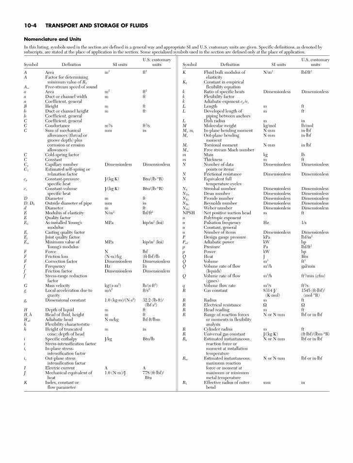
Nomenclature and Units
In this listing, symbols used in the section are defined in a general way and appropriate SI and U.S. customary units are given. Specific definitions, as denoted bysubscripts, are stated at the place of application in the section. Some specialized symbols used in the section are defined only at the place of application.
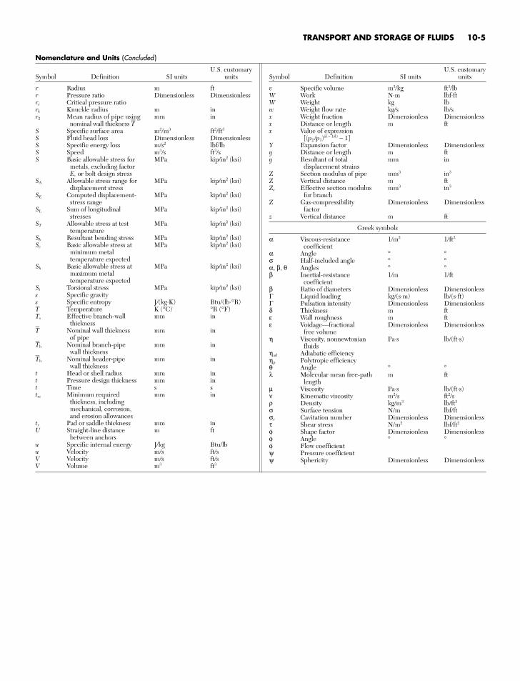
U.S. customarySymbol Definition SI units units
r Radius m ftr Pressure ratio Dimensionless Dimensionlessrc Critical pressure ratiork Knuckle radius m inr2 Mean radius of pipe using mm in
nominal wall thickness TS Specific surface area m2/m3 ft2/ft3
S Fluid head loss Dimensionless DimensionlessS Specific energy loss m/s2 lbf/lbS Speed m3/s ft3/sS Basic allowable stress for MPa kip/in2 (ksi)
metals, excluding factorE, or bolt design stress
SA Allowable stress range for MPa kip/in2 (ksi)displacement stress
SE Computed displacement- MPa kip/in2 (ksi)stress range
SL Sum of longitudinal MPa kip/in2 (ksi)stresses
ST Allowable stress at test MPa kip/in2 (ksi)temperature
Sb Resultant bending stress MPa kip/in2 (ksi)Sc Basic allowable stress at MPa kip/in2 (ksi)
minimum metaltemperature expected
Sh Basic allowable stress at MPa kip/in2 (ksi)maximum metaltemperature expected
St Torsional stress MPa kip/in2 (ksi)s Specific gravitys Specific entropy J/(kg⋅K) Btu/(lb⋅°R)T Temperature K (°C) °R (°F)Ts Effective branch-wall mm in
thicknessT Nominal wall thickness mm in
of pipeTb Nominal branch-pipe mm in
wall thicknessTh Nominal header-pipe mm in
wall thicknesst Head or shell radius mm int Pressure design thickness mm int Time s stm Minimum required mm in
thickness, includingmechanical, corrosion,and erosion allowances
tr Pad or saddle thickness mm inU Straight-line distance m ft
between anchorsu Specific internal energy J/kg Btu/lbu Velocity m/s ft/sV Velocity m/s ft/sV Volume m3 ft3
U.S. customarySymbol Definition SI units units
v Specific volume m3/kg ft3/lbW Work N⋅m lbf⋅ftW Weight kg lbw Weight flow rate kg/s lb/sx Weight fraction Dimensionless Dimensionlessx Distance or length m ftx Value of expression
[(p2 /p1)(k − 1/k) − 1]Y Expansion factor Dimensionless Dimensionlessy Distance or length m fty Resultant of total mm in
displacement strainsZ Section modulus of pipe mm3 in3
Z Vertical distance m ftZe Effective section modulus mm3 in3
for branchZ Gas-compressibility Dimensionless Dimensionless
factorz Vertical distance m ft
Greek symbols
α Viscous-resistance 1/m2 1/ft2
coefficientα Angle ° °σ Half-included angle ° °α, β, θ Angles ° °β Inertial-resistance 1/m 1/ft
coefficientβ Ratio of diameters Dimensionless DimensionlessΓ Liquid loading kg/(s⋅m) lb/(s⋅ft)Γ Pulsation intensity Dimensionless Dimensionlessδ Thickness m ftε Wall roughness m ftε Voidage—fractional Dimensionless Dimensionless
free volumeη Viscosity, nonnewtonian Pa⋅s lb/(ft⋅s)
fluidsηad Adiabatic efficiencyηp Polytropic efficiencyθ Angle ° °λ Molecular mean free-path m ft
lengthµ Viscosity Pa⋅s lb/(ft⋅s)ν Kinematic viscosity m2/s ft2/sρ Density kg/m3 lb/ft3
σ Surface tension N/m lbf/ftσc Cavitation number Dimensionless Dimensionlessτ Shear stress N/m2 lbf/ft2
φ Shape factor Dimensionless Dimensionlessφ Angle ° °φ Flow coefficientψ Pressure coefficientψ Sphericity Dimensionless Dimensionless
Nomenclature and Units (Concluded )
TRANSPORT AND STORAGE OF FLUIDS 10-5
GENERAL REFERENCES: ASME, Performance Test Code on Compressors andExhausters, PTC 10-1997, American Society of Mechanical Engineers (ASME),New York, 1997. Norman A. Anderson, Instrumentation for Process Measure-ment and Control, 3d ed., CRC Press, Boca Raton, Fla., 1997. Roger C. Baker,Flow Measurement Handbook: Industrial Designs, Operating Principles, Perfor-mance, and Applications, Cambridge University Press, Cambridge, United King-dom, 2000. Roger C. Baker, An Introductory Guide to Flow Measurement,ASME, New York, 2003. Howard S. Bean, ed., Fluid Meters—Their Theory andApplication—Report of the ASME Research Committee on Fluid Meters, 6th ed.,ASME, New York, 1971. Douglas M. Considine, Editor-in-Chief, Process/Indus-trial Instruments and Controls Handbook, 4th ed., McGraw-Hill, New York,1993. Bela G. Liptak, Editor-in-Chief, Process Measurement and Analysis, 4thed., CRC Press, Boca Raton, Fla., 2003. Richard W. Miller, Flow MeasurementEngineering Handbook, 3d ed., McGraw-Hill, New York, 1996. Ower andPankhurst, The Measurement of Air Flow, Pergamon, Oxford, United Kingdom,1966. Brian Price et al., Engineering Data Book, 12th ed., Gas Processors Sup-pliers Association, Tulsa, Okla., 2004. David W. Spitzer, Flow Measurement, 2ded., Instrument Society of America, Research Triangle Park, N.C., 2001. DavidW. Spitzer, Industrial Flow Measurement, 3d ed., Instrument Society of America,Research Triangle Park, N.C., 2005.
INTRODUCTION
The flow rate of fluids is a critical variable in most chemical engineer-ing applications, ranging from flows in the process industries to envi-ronmental flows and to flows within the human body. Flow is definedas mass flow or volume flow per unit of time at specified temperatureand pressure conditions for a given fluid. This subsection deals withthe techniques of measuring pressure, temperature, velocities, andflow rates of flowing fluids. For more detailed discussion of these vari-ables, consult Sec. 8. Section 8 introduces methods of measuring flowrate, temperature, and pressure. This subsection builds on the cover-age in Sec. 8 with emphasis on measurement of the flow of fluids.
PROPERTIES AND BEHAVIOR OF FLUIDS
Transportation and the storage of fluids (gases and liquids) involvesthe understanding of the properties and behavior of fluids. The studyof fluid dynamics is the study of fluids and their motion in a force field.
Flows can be classified into two major categories: (a) incompressibleand (b) compressible flow. Most liquids fall into the incompressible-flow category, while most gases are compressible in nature. A perfectfluid can be defined as a fluid that is nonviscous and nonconduct-ing. Fluid flow, compressible or incompressible, can be classified bythe ratio of the inertial forces to the viscous forces. This ratio is repre-sented by the Reynolds number (NRe). At a low Reynolds number, theflow is considered to be laminar, and at high Reynolds numbers, the
flow is considered to be turbulent. The limiting types of flow are theinertialess flow, sometimes called Stokes flow, and the inviscid flow thatoccurs at an infinitely large Reynolds number. Reynolds numbers(dimensionless) for flow in a pipe is given as:
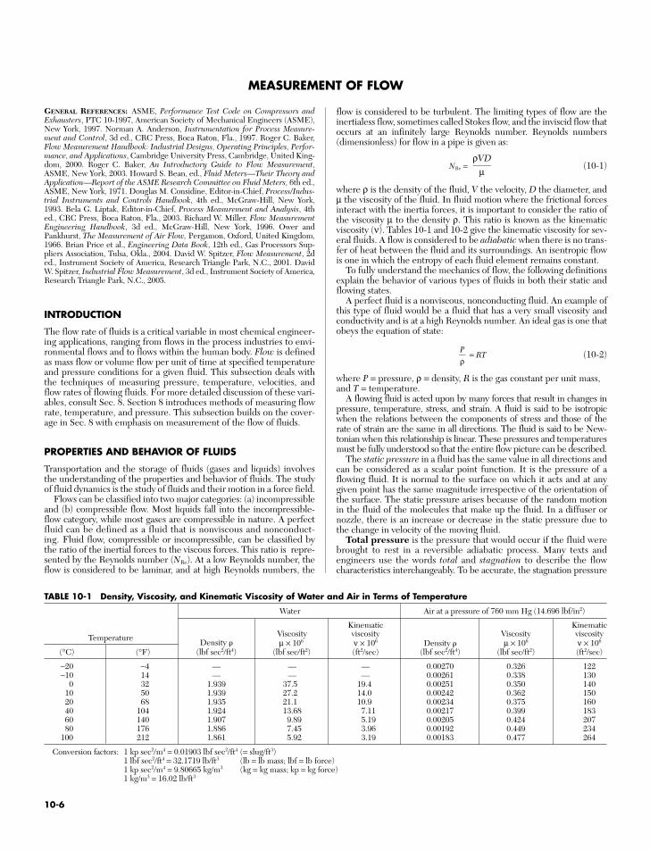
NRe = (10-1)
where ρ is the density of the fluid, V the velocity, D the diameter, andµ the viscosity of the fluid. In fluid motion where the frictional forcesinteract with the inertia forces, it is important to consider the ratio ofthe viscosity µ to the density ρ. This ratio is known as the kinematicviscosity (ν). Tables 10-1 and 10-2 give the kinematic viscosity for sev-eral fluids. A flow is considered to be adiabatic when there is no trans-fer of heat between the fluid and its surroundings. An isentropic flowis one in which the entropy of each fluid element remains constant.
To fully understand the mechanics of flow, the following definitionsexplain the behavior of various types of fluids in both their static andflowing states.
A perfect fluid is a nonviscous, nonconducting fluid. An example ofthis type of fluid would be a fluid that has a very small viscosity andconductivity and is at a high Reynolds number. An ideal gas is one thatobeys the equation of state:
= RT (10-2)
where P = pressure, ρ = density, R is the gas constant per unit mass,and T = temperature.
A flowing fluid is acted upon by many forces that result in changes inpressure, temperature, stress, and strain. A fluid is said to be isotropicwhen the relations between the components of stress and those of therate of strain are the same in all directions. The fluid is said to be New-tonian when this relationship is linear. These pressures and temperaturesmust be fully understood so that the entire flow picture can be described.
The static pressure in a fluid has the same value in all directions andcan be considered as a scalar point function. It is the pressure of aflowing fluid. It is normal to the surface on which it acts and at anygiven point has the same magnitude irrespective of the orientation ofthe surface. The static pressure arises because of the random motionin the fluid of the molecules that make up the fluid. In a diffuser ornozzle, there is an increase or decrease in the static pressure due tothe change in velocity of the moving fluid.
Total pressure is the pressure that would occur if the fluid werebrought to rest in a reversible adiabatic process. Many texts andengineers use the words total and stagnation to describe the flowcharacteristics interchangeably. To be accurate, the stagnation pressure
Pρ
ρVD
µ
MEASUREMENT OF FLOW
TABLE 10-1 Density, Viscosity, and Kinematic Viscosity of Water and Air in Terms of Temperature
Water Air at a pressure of 760 mm Hg (14.696 lbf/in2)
Kinematic KinematicViscosity viscosity Viscosity viscosityTemperature Density µ × 106 ν × 106 Density µ × 106 ν × 106
(°C) (°F) (lbf sec2/ft4) (lbf sec/ft2) (ft2/sec) (lbf sec2/ft4) (lbf sec/ft2) (ft2/sec)
−20 −4 — — — 0.00270 0.326 122−10 14 — — — 0.00261 0.338 130
0 32 1.939 37.5 19.4 0.00251 0.350 14010 50 1.939 27.2 14.0 0.00242 0.362 15020 68 1.935 21.1 10.9 0.00234 0.375 16040 104 1.924 13.68 7.11 0.00217 0.399 18360 140 1.907 9.89 5.19 0.00205 0.424 20780 176 1.886 7.45 3.96 0.00192 0.449 234
100 212 1.861 5.92 3.19 0.00183 0.477 264
Conversion factors: 1 kp sec2/m4 = 0.01903 lbf sec2/ft4 (= slug/ft3)1 lbf sec2/ft4 = 32.1719 lb/ft3 (lb = lb mass; lbf = lb force)1 kp sec2/m4 = 9.80665 kg/m3 (kg = kg mass; kp = kg force)1 kg/m3 = 16.02 lb/ft3
10-6
is the pressure that would occur if the fluid were brought to rest adi-abatically or diabatically.
Total pressure will only change in a fluid if shaft work or work ofextraneous forces are introduced. Therefore, total pressure wouldincrease in the impeller of a compressor or pump; it would remainconstant in the diffuser. Similarly, total pressure would decrease in theturbine impeller but would remain constant in the nozzles.
Static temperature is the temperature of the flowing fluid. Like sta-tic pressure, it arises because of the random motion of the fluid mole-cules. Static temperature is in most practical installations impossibleto measure since it can be measured only by a thermometer or ther-mocouple at rest relative to the flowing fluid that is moving with thefluid. Static temperature will increase in a diffuser and decrease in anozzle.
Total temperature is the temperature that would occur when thefluid is brought to rest in a reversible adiabatic manner. Just like itscounterpart total pressure, total and stagnation temperatures are usedinterchangeably by many test engineers.
Dynamic temperature and pressure are the difference between thetotal and static conditions.
Pd = PT − Ps (10-3)
Td = TT − Ts (10-4)
where subscript d refers to dynamic, T to total, and s to static.Another helpful formula is:
PK = ρV2 (10-5)
For incompressible fluids, PK = Pd.
TOTAL TEMPERATURE
For most points requiring temperature monitoring, either thermo-couples or resistive thermal detectors (RTDs) can be used. Each typeof temperature transducer has its own advantages and disadvantages,and both should be considered when temperature is to be measured.Since there is considerable confusion in this area, a short discussion ofthe two types of transducers is necessary.
Thermocouples The various types of thermocouples providetransducers suitable for measuring temperatures from −330 to 5000°F(−201 to 2760°C). Thermocouples function by producing a voltageproportional to the temperature differences between two junctions ofdissimilar metals. By measuring this voltage, the temperature differ-ence can be determined. It is assumed that the temperature is knownat one of the junctions; therefore, the temperature at the other junc-tion can be determined. Since the thermocouples produce a voltage,no external power supply is required to the test junction; however, foraccurate measurement, a reference junction is required. For a tem-perature monitoring system, reference junctions must be placed ateach thermocouple or similar thermocouple wire installed from thethermocouple to the monitor where there is a reference junction.Properly designed thermocouple systems can be accurate to approxi-mately ±2°F (±1°C).
Resistive Thermal Detectors (RTDs) RTDs determine tem-perature by measuring the change in resistance of an element due totemperature. Platinum is generally utilized in RTDs because itremains mechanically and electrically stable, resists contaminations,and can be highly refined. The useful range of platinum RTDs is
12
−454–1832°F (−270−1000°C). Since the temperature is deter-mined by the resistance in the element, any type of electrical con-ductor can be utilized to connect the RTD to the indicator;however, an electrical current must be provided to the RTD. A prop-erly designed temperature monitoring system utilizing RTDs can beaccurate ±0.02°F (±0.01°C).
STATIC TEMPERATURE
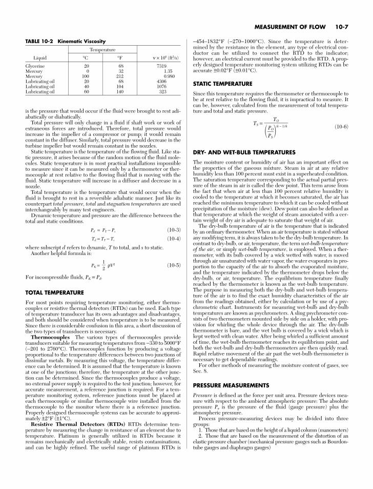
Since this temperature requires the thermometer or thermocouple tobe at rest relative to the flowing fluid, it is impractical to measure. Itcan be, however, calculated from the measurement of total tempera-ture and total and static pressure.
TS =(10-6)
DRY- AND WET-BULB TEMPERATURES
The moisture content or humidity of air has an important effect onthe properties of the gaseous mixture. Steam in air at any relativehumidity less than 100 percent must exist in a superheated condition.The saturation temperature corresponding to the actual partial pres-sure of the steam in air is called the dew point. This term arose fromthe fact that when air at less than 100 percent relative humidity iscooled to the temperature at which it becomes saturated, the air hasreached the minimum temperature to which it can be cooled withoutprecipitation of the moisture (dew). Dew point can also be defined asthat temperature at which the weight of steam associated with a cer-tain weight of dry air is adequate to saturate that weight of air.
The dry-bulb temperature of air is the temperature that is indicatedby an ordinary thermometer. When an air temperature is stated withoutany modifying term, it is always taken to be the dry-bulb temperature. Incontrast to dry-bulb, or air, temperature, the term wet-bulb temperatureof the air, or simply wet-bulb temperature, is employed. When a ther-mometer, with its bulb covered by a wick wetted with water, is movedthrough air unsaturated with water vapor, the water evaporates in pro-portion to the capacity of the air to absorb the evaporated moisture,and the temperature indicated by the thermometer drops below thedry-bulb, or air, temperature. The equilibrium temperature finallyreached by the thermometer is known as the wet-bulb temperature.The purpose in measuring both the dry-bulb and wet-bulb tempera-ture of the air is to find the exact humidity characteristics of the airfrom the readings obtained, either by calculation or by use of a psy-chrometric chart. Instruments for measuring wet-bulb and dry-bulbtemperatures are known as psychrometers. A sling psychrometer con-sists of two thermometers mounted side by side on a holder, with pro-vision for whirling the whole device through the air. The dry-bulbthermometer is bare, and the wet bulb is covered by a wick which iskept wetted with clean water. After being whirled a sufficient amountof time, the wet-bulb thermometer reaches its equilibrium point, andboth the wet-bulb and dry-bulb thermometers are then quickly read.Rapid relative movement of the air past the wet-bulb thermometer isnecessary to get dependable readings.
For other methods of measuring the moisture content of gases, seeSec. 8.
PRESSURE MEASUREMENTS
Pressure is defined as the force per unit area. Pressure devices mea-sure with respect to the ambient atmospheric pressure: The absolutepressure Pa is the pressure of the fluid (gauge pressure) plus theatmospheric pressure.
Process pressure-measuring devices may be divided into threegroups:
1. Those that are based on the height of a liquid column (manometers)2. Those that are based on the measurement of the distortion of an
elastic pressure chamber (mechanical pressure gauges such as Bourdon-tube gauges and diaphragm gauges)
TO
PP
S
O
(k − 1)/k
MEASUREMENT OF FLOW 10-7
TABLE 10-2 Kinematic Viscosity
Temperature
Liquid °C °F ν × 106 (ft2/s)
Glycerine 20 68 7319Mercury 0 32 1.35Mercury 100 212 0.980Lubricating oil 20 68 4306Lubricating oil 40 104 1076Lubricating oil 60 140 323
3. Electric sensing devices (strain gauges, piezoresistive transduc-ers, and piezoelectric transducers)
This subsection contains an expanded discussion of manometricmethods. See Sec. 8 for other methods.
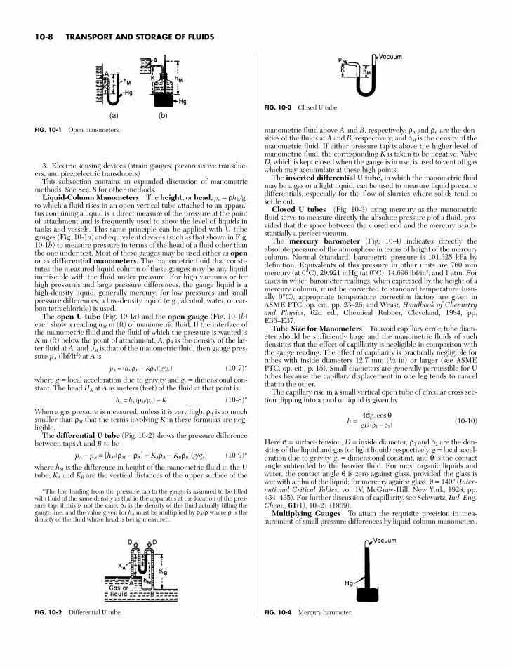
Liquid-Column Manometers The height, or head, pn = ρhggc
to which a fluid rises in an open vertical tube attached to an appara-tus containing a liquid is a direct measure of the pressure at the pointof attachment and is frequently used to show the level of liquids intanks and vessels. This same principle can be applied with U-tubegauges (Fig. 10-1a) and equivalent devices (such as that shown in Fig.10-1b) to measure pressure in terms of the head of a fluid other thanthe one under test. Most of these gauges may be used either as openor as differential manometers. The manometric fluid that consti-tutes the measured liquid column of these gauges may be any liquidimmiscible with the fluid under pressure. For high vacuums or forhigh pressures and large pressure differences, the gauge liquid is ahigh-density liquid, generally mercury; for low pressures and smallpressure differences, a low-density liquid (e.g., alcohol, water, or car-bon tetrachloride) is used.
The open U tube (Fig. 10-1a) and the open gauge (Fig. 10-1b)each show a reading hM m (ft) of manometric fluid. If the interface ofthe manometric fluid and the fluid of which the pressure is wanted isK m (ft) below the point of attachment, A, ρA is the density of the lat-ter fluid at A, and ρM is that of the manometric fluid, then gauge pres-sure pA (lbf/ft2) at A is
pA = (hMρM − KρA)(ggc) (10-7)*
where g = local acceleration due to gravity and gc = dimensional con-stant. The head HA at A as meters (feet) of the fluid at that point is
hA = hM(ρMρA) − K (10-8)*
When a gas pressure is measured, unless it is very high, ρA is so muchsmaller than ρM that the terms involving K in these formulas are neg-ligible.
The differential U tube (Fig. 10-2) shows the pressure differencebetween taps A and B to be
pA − pB = [hM(ρM − ρA) + KAρA − KBρB](ggc) (10-9)*
where hM is the difference in height of the manometric fluid in the Utube; KA and KB are the vertical distances of the upper surface of the
manometric fluid above A and B, respectively; ρA and ρB are the den-sities of the fluids at A and B, respectively; and ρM is the density of themanometric fluid. If either pressure tap is above the higher level ofmanometric fluid, the corresponding K is taken to be negative. ValveD, which is kept closed when the gauge is in use, is used to vent off gaswhich may accumulate at these high points.
The inverted differential U tube, in which the manometric fluidmay be a gas or a light liquid, can be used to measure liquid pressuredifferentials, especially for the flow of slurries where solids tend tosettle out.
Closed U tubes (Fig. 10-3) using mercury as the manometricfluid serve to measure directly the absolute pressure p of a fluid, pro-vided that the space between the closed end and the mercury is sub-stantially a perfect vacuum.
The mercury barometer (Fig. 10-4) indicates directly theabsolute pressure of the atmosphere in terms of height of the mercurycolumn. Normal (standard) barometric pressure is 101.325 kPa bydefinition. Equivalents of this pressure in other units are 760 mmmercury (at 0°C), 29.921 inHg (at 0°C), 14.696 lbf/in2, and 1 atm. Forcases in which barometer readings, when expressed by the height of amercury column, must be corrected to standard temperature (usu-ally 0°C), appropriate temperature correction factors are given inASME PTC, op. cit., pp. 23–26; and Weast, Handbook of Chemistryand Physics, 62d ed., Chemical Rubber, Cleveland, 1984, pp.E36–E37.
Tube Size for Manometers To avoid capillary error, tube diam-eter should be sufficiently large and the manometric fluids of suchdensities that the effect of capillarity is negligible in comparison withthe gauge reading. The effect of capillarity is practically negligible fortubes with inside diameters 12.7 mm (1⁄2 in) or larger (see ASMEPTC, op. cit., p. 15). Small diameters are generally permissible for Utubes because the capillary displacement in one leg tends to cancelthat in the other.
The capillary rise in a small vertical open tube of circular cross sec-tion dipping into a pool of liquid is given by
h = (10-10)
Here σ = surface tension, D = inside diameter, ρ1 and ρ2 are the den-sities of the liquid and gas (or light liquid) respectively, g = local accel-eration due to gravity, gc = dimensional constant, and θ is the contactangle subtended by the heavier fluid. For most organic liquids andwater, the contact angle θ is zero against glass, provided the glass iswet with a film of the liquid; for mercury against glass, θ = 140° (Inter-national Critical Tables, vol. IV, McGraw-Hill, New York, 1928, pp.434–435). For further discussion of capillarity, see Schwartz, Ind. Eng.Chem., 61(1), 10–21 (1969).
Multiplying Gauges To attain the requisite precision in mea-surement of small pressure differences by liquid-column manometers,
4σgc cos θgD(ρ1 − ρ2)
10-8 TRANSPORT AND STORAGE OF FLUIDS
(a) (b)
FIG. 10-1 Open manometers.
FIG. 10-2 Differential U tube.
FIG. 10-3 Closed U tube.
*The line leading from the pressure tap to the gauge is assumed to be filledwith fluid of the same density as that in the apparatus at the location of the pres-sure tap; if this is not the case, ρA is the density of the fluid actually filling thegauge line, and the value given for hA must be multiplied by ρAρ where ρ is thedensity of the fluid whose head is being measured.
FIG. 10-4 Mercury barometer.
means must often be devised to magnify the readings. Of the schemesthat follow, the second and third may give tenfold multiplication; thefourth, as much as thirtyfold. In general, the greater the multiplication,the more elaborate must be the precautions in the use of the gauge ifthe gain in precision is not to be illusory.
1. Change of manometric fluid. In open manometers, choose afluid of lower density. In differential manometers, choose a fluid suchthat the difference between its density and that of the fluid beingmeasured is as small as possible.
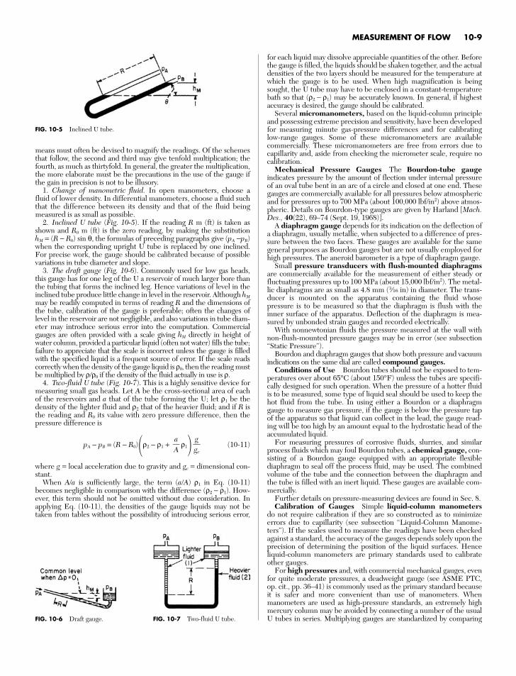
2. Inclined U tube (Fig. 10-5). If the reading R m (ft) is taken asshown and R0 m (ft) is the zero reading, by making the substitutionhM = (R − R0) sin θ, the formulas of preceding paragraphs give (pA −pB)when the corresponding upright U tube is replaced by one inclined.For precise work, the gauge should be calibrated because of possiblevariations in tube diameter and slope.
3. The draft gauge (Fig. 10-6). Commonly used for low gas heads,this gauge has for one leg of the U a reservoir of much larger bore thanthe tubing that forms the inclined leg. Hence variations of level in theinclined tube produce little change in level in the reservoir. Although hM
may be readily computed in terms of reading R and the dimensions ofthe tube, calibration of the gauge is preferable; often the changes oflevel in the reservoir are not negligible, and also variations in tube diam-eter may introduce serious error into the computation. Commercialgauges are often provided with a scale giving hM directly in height ofwater column, provided a particular liquid (often not water) fills the tube;failure to appreciate that the scale is incorrect unless the gauge is filledwith the specified liquid is a frequent source of error. If the scale readscorrectly when the density of the gauge liquid is ρ0, then the reading mustbe multiplied by ρρ0 if the density of the fluid actually in use is ρ.
4. Two-fluid U tube (Fig. 10-7). This is a highly sensitive device formeasuring small gas heads. Let A be the cross-sectional area of eachof the reservoirs and a that of the tube forming the U; let ρ1 be thedensity of the lighter fluid and ρ2 that of the heavier fluid; and if R isthe reading and R0 its value with zero pressure difference, then thepressure difference is
pA − pB = (R − R0)ρ2 − ρ1 + ρ1 (10-11)
where g = local acceleration due to gravity and gc = dimensional con-stant.
When A/a is sufficiently large, the term (a/A) ρ1 in Eq. (10-11)becomes negligible in comparison with the difference (ρ2 − ρ1). How-ever, this term should not be omitted without due consideration. Inapplying Eq. (10-11), the densities of the gauge liquids may not betaken from tables without the possibility of introducing serious error,
ggc
aA
for each liquid may dissolve appreciable quantities of the other. Beforethe gauge is filled, the liquids should be shaken together, and the actualdensities of the two layers should be measured for the temperature atwhich the gauge is to be used. When high magnification is beingsought, the U tube may have to be enclosed in a constant-temperaturebath so that (ρ2 − ρ1) may be accurately known. In general, if highestaccuracy is desired, the gauge should be calibrated.
Several micromanometers, based on the liquid-column principleand possessing extreme precision and sensitivity, have been developedfor measuring minute gas-pressure differences and for calibratinglow-range gauges. Some of these micromanometers are availablecommercially. These micromanometers are free from errors due tocapillarity and, aside from checking the micrometer scale, require nocalibration.
Mechanical Pressure Gauges The Bourdon-tube gaugeindicates pressure by the amount of flection under internal pressureof an oval tube bent in an arc of a circle and closed at one end. Thesegauges are commercially available for all pressures below atmosphericand for pressures up to 700 MPa (about 100,000 lbf/in2) above atmos-pheric. Details on Bourdon-type gauges are given by Harland [Mach.Des., 40(22), 69–74 (Sept. 19, 1968)].
A diaphragm gauge depends for its indication on the deflection ofa diaphragm, usually metallic, when subjected to a difference of pres-sure between the two faces. These gauges are available for the samegeneral purposes as Bourdon gauges but are not usually employed forhigh pressures. The aneroid barometer is a type of diaphragm gauge.
Small pressure transducers with flush-mounted diaphragmsare commercially available for the measurement of either steady orfluctuating pressures up to 100 MPa (about 15,000 lbf/in2). The metal-lic diaphragms are as small as 4.8 mm (3⁄16 in) in diameter. The trans-ducer is mounted on the apparatus containing the fluid whosepressure is to be measured so that the diaphragm is flush with theinner surface of the apparatus. Deflection of the diaphragm is mea-sured by unbonded strain gauges and recorded electrically.
With nonnewtonian fluids the pressure measured at the wall withnon-flush-mounted pressure gauges may be in error (see subsection“Static Pressure”).
Bourdon and diaphragm gauges that show both pressure and vacuumindications on the same dial are called compound gauges.
Conditions of Use Bourdon tubes should not be exposed to tem-peratures over about 65°C (about 150°F) unless the tubes are specifi-cally designed for such operation. When the pressure of a hotter fluidis to be measured, some type of liquid seal should be used to keep thehot fluid from the tube. In using either a Bourdon or a diaphragmgauge to measure gas pressure, if the gauge is below the pressure tapof the apparatus so that liquid can collect in the lead, the gauge read-ing will be too high by an amount equal to the hydrostatic head of theaccumulated liquid.
For measuring pressures of corrosive fluids, slurries, and similarprocess fluids which may foul Bourdon tubes, a chemical gauge, con-sisting of a Bourdon gauge equipped with an appropriate flexiblediaphragm to seal off the process fluid, may be used. The combinedvolume of the tube and the connection between the diaphragm andthe tube is filled with an inert liquid. These gauges are available com-mercially.
Further details on pressure-measuring devices are found in Sec. 8.Calibration of Gauges Simple liquid-column manometers
do not require calibration if they are so constructed as to minimizeerrors due to capillarity (see subsection “Liquid-Column Manome-ters”). If the scales used to measure the readings have been checkedagainst a standard, the accuracy of the gauges depends solely upon theprecision of determining the position of the liquid surfaces. Henceliquid-column manometers are primary standards used to calibrateother gauges.
For high pressures and, with commercial mechanical gauges, evenfor quite moderate pressures, a deadweight gauge (see ASME PTC,op. cit., pp. 36–41) is commonly used as the primary standard becauseit is safer and more convenient than use of manometers. Whenmanometers are used as high-pressure standards, an extremely highmercury column may be avoided by connecting a number of the usualU tubes in series. Multiplying gauges are standardized by comparing
MEASUREMENT OF FLOW 10-9
FIG. 10-5 Inclined U tube.
FIG. 10-6 Draft gauge. FIG. 10-7 Two-fluid U tube.
them with a micromanometer. Procedure in the calibration of a gaugeconsists merely of connecting it, in parallel with a standard gauge, to areservoir wherein constant pressure may be maintained. Readings ofthe unknown gauge are then made for various reservoir pressures asdetermined by the standard.
Calibration of high-vacuum gauges is described by Sellenger[Vacuum, 18(12), 645–650 (1968)].
STATIC PRESSURE
Local Static Pressure In a moving fluid, the local static pressureis equal to the pressure on a surface which moves with the fluid or tothe normal pressure (for newtonian fluids) on a stationary surfacewhich parallels the flow. The pressure on such a surface is measured bymaking a small hole perpendicular to the surface and connecting theopening to a pressure-sensing element (Fig. 10-8a). The hole is knownas a piezometer opening or pressure tap.
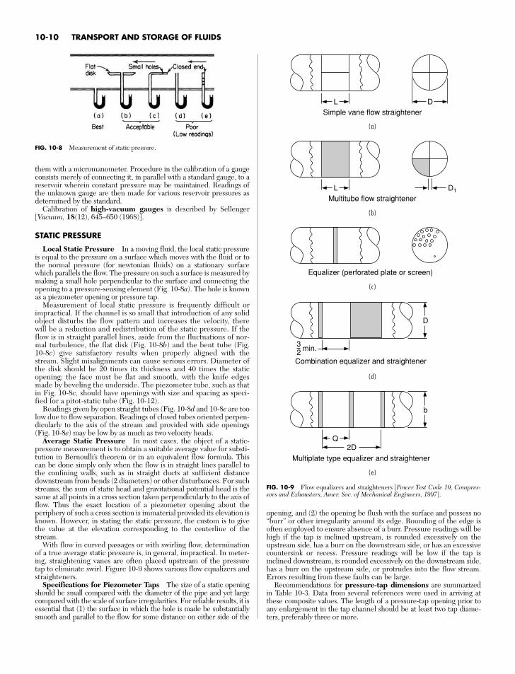
Measurement of local static pressure is frequently difficult orimpractical. If the channel is so small that introduction of any solidobject disturbs the flow pattern and increases the velocity, therewill be a reduction and redistribution of the static pressure. If theflow is in straight parallel lines, aside from the fluctuations of nor-mal turbulence, the flat disk (Fig. 10-8b) and the bent tube (Fig.10-8c) give satisfactory results when properly aligned with thestream. Slight misalignments can cause serious errors. Diameter ofthe disk should be 20 times its thickness and 40 times the staticopening; the face must be flat and smooth, with the knife edgesmade by beveling the underside. The piezometer tube, such as thatin Fig. 10-8c, should have openings with size and spacing as speci-fied for a pitot-static tube (Fig. 10-12).
Readings given by open straight tubes (Fig. 10-8d and 10-8e are toolow due to flow separation. Readings of closed tubes oriented perpen-dicularly to the axis of the stream and provided with side openings(Fig. 10-8e) may be low by as much as two velocity heads.
Average Static Pressure In most cases, the object of a static-pressure measurement is to obtain a suitable average value for substi-tution in Bernoulli’s theorem or in an equivalent flow formula. Thiscan be done simply only when the flow is in straight lines parallel tothe confining walls, such as in straight ducts at sufficient distancedownstream from bends (2 diameters) or other disturbances. For suchstreams, the sum of static head and gravitational potential head is thesame at all points in a cross section taken perpendicularly to the axis offlow. Thus the exact location of a piezometer opening about theperiphery of such a cross section is immaterial provided its elevation isknown. However, in stating the static pressure, the custom is to givethe value at the elevation corresponding to the centerline of thestream.
With flow in curved passages or with swirling flow, determinationof a true average static pressure is, in general, impractical. In meter-ing, straightening vanes are often placed upstream of the pressuretap to eliminate swirl. Figure 10-9 shows various flow equalizers andstraighteners.
Specifications for Piezometer Taps The size of a static openingshould be small compared with the diameter of the pipe and yet largecompared with the scale of surface irregularities. For reliable results, it isessential that (1) the surface in which the hole is made be substantiallysmooth and parallel to the flow for some distance on either side of the
opening, and (2) the opening be flush with the surface and possess no“burr” or other irregularity around its edge. Rounding of the edge isoften employed to ensure absence of a burr. Pressure readings will behigh if the tap is inclined upstream, is rounded excessively on theupstream side, has a burr on the downstream side, or has an excessivecountersink or recess. Pressure readings will be low if the tap isinclined downstream, is rounded excessively on the downstream side,has a burr on the upstream side, or protrudes into the flow stream.Errors resulting from these faults can be large.
Recommendations for pressure-tap dimensions are summarizedin Table 10-3. Data from several references were used in arriving atthese composite values. The length of a pressure-tap opening prior toany enlargement in the tap channel should be at least two tap diame-ters, preferably three or more.
10-10 TRANSPORT AND STORAGE OF FLUIDS
FIG. 10-8 Measurement of static pressure.
LSimple vane flow straightener
D
Equalizer (perforated plate or screen)
LMultitube flow straightener
32 min.
D
Combination equalizer and straightener
D1
Q2D
b
Multiplate type equalizer and straightener
( d )
( b )
( a )
( c )
( e )
FIG. 10-9 Flow equalizers and straighteners [Power Test Code 10, Compres-sors and Exhausters, Amer. Soc. of Mechanical Engineers, 1997].
A piezometer ring is a toroidal manifold into which are connectedseveral sidewall static taps located around the perimeter of a commoncross section. Its intent is to give an average pressure if differences inpressure other than those due to static head exist around the perime-ter. However, there is generally no assurance that a true average isprovided thereby. The principal advantage of the ring is that use ofseveral holes in place of a single hole reduces the possibility of com-pletely plugging the static openings.
For information on prediction of static-hole error, see Shaw, J.Fluid Mech., 7, 550–564 (1960); Livesey, Jackson, and Southern,Aircr. Eng., 34, 43–47 (February 1962).
For nonnewtonian fluids, pressure readings with taps may also below because of fluid-elasticity effects. This error can be largely elimi-nated by using flush-mounted diaphragms.
For information on the pressure-hole error for nonnewtonian flu-ids, see Han and Kim, Trans. Soc. Rheol., 17, 151–174 (1973);Novotny and Eckert, Trans. Soc. Rheol., 17, 227–241 (1973); andHigashitani and Lodge, Trans. Soc. Rheol., 19, 307–336 (1975).
VELOCITY MEASUREMENTS
Measurement of flow can be based on the measurement of velocity inducts or pipes by using devices such as pitot tubes and hot wireanemometers. The local velocity is measured at various sectionsof a conduit and then averaged for the area under consideration.
= A × V = Q (10-12)
where w = mass flow rate, lbms, kgsρ = density, lbmft3, kgm3
A = area, fts, msV = velocity, fts, msQ = volumetric flow rate, ft3s, m3s
Equation (10-12) shows that the fluid density directly affects the rela-tionship between mass flow rate and both velocity and volumetric flowrate. Liquid temperature affects liquid density and hence volumetricflow rate at a constant mass flow rate. Liquid density is relatively insen-sitive to pressure. Both temperature and pressure affect gas densityand thus volumetric flow rate.
Variables Affecting Measurement Flow measurement meth-ods may sense local fluid velocity, volumetric flow rate, total or cumu-lative volumetric flow (the integral of volumetric flow rate withrespect to elapsed time), mass flow rate, and total mass flow.
Velocity Profile Effects Many variables can influence the accu-racy of specific flow measurement methods. For example, the velocityprofile in a closed conduit affects many types of flow-measuring devices.The velocity of a fluid varies from zero at the wall and at other station-ary solid objects in the flow channel to a maximum at a distance fromthe wall. In the entry region of a conduit, the velocity field mayapproach plug flow and a constant velocity across the conduit, drop-ping to zero only at the wall. As a newtonian fluid progresses down apipe, a velocity profile develops that is parabolic for laminar flow[Eq. (6-41)] and that approaches plug flow for highly turbulent flow.Once a steady flow profile has developed, the flow is said to be fullydeveloped; the length of conduit necessary to achieve fully devel-
wρ
oped flow is called the entrance region. For long cylindrical, hori-zontal pipe (L < 40D, where D is the inside diameter of the pipe andL is the upstream length of pipe), the velocity profile becomes fullydeveloped. Velocity profiles in flowing fluids are discussed in greaterdetail in Sec. 6 (p. 6-11).
For steady-state, isothermal, single-phase, uniform, fully developednewtonian flow in straight pipes, the velocity is greatest at the centerof the channel and symmetric about the axis of the pipe. Of thoseflowmeters that are dependent on the velocity profile, they are usuallycalibrated for this type of flow. Thus any disturbances in flow condi-tions can affect flowmeter readings.
Upstream and downstream disturbances in the flow field are causedby valves, elbows, and other types of fittings. Two upstream elbows intwo perpendicular planes will impart swirl in the fluid downstream.Swirl, similar to atypical velocity profiles, can lead to erroneous flowmeasurements. Although the effect is not as great as in upstream flowdisturbances, downstream flow disturbances can also lead to erroneousflow measurements.
Other Flow Disturbances Other examples of deviations fromfully developed, single-phase newtonian flow include nonnewtonianflow, pulsating flow, cavitation, multiphase flow, boundary layer flows,and nonisothermal flows. See Sec. 6.
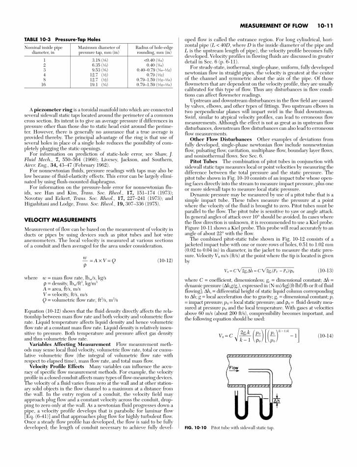
Pitot Tubes The combination of pitot tubes in conjunction withsidewall static taps measures local or point velocities by measuring thedifference between the total pressure and the static pressure. Thepitot tube shown in Fig. 10-10 consists of an impact tube whose open-ing faces directly into the stream to measure impact pressure, plus oneor more sidewall taps to measure local static pressure.
Dynamic pressure may be measured by use of a pitot tube that is asimple impact tube. These tubes measure the pressure at a pointwhere the velocity of the fluid is brought to zero. Pitot tubes must beparallel to the flow. The pitot tube is sensitive to yaw or angle attack.In general angles of attack over 10° should be avoided. In cases wherethe flow direction is unknown, it is recommended to use a Kiel probe.Figure 10-11 shows a Kiel probe. This probe will read accurately to anangle of about 22° with the flow.
The combined pitot-static tube shown in Fig. 10-12 consists of ajacketed impact tube with one or more rows of holes, 0.51 to 1.02 mm(0.02 to 0.04 in) in diameter, in the jacket to measure the static pres-sure. Velocity V0 m/s (ft/s) at the point where the tip is located is givenby
V0 = C2gc∆h = C2gc(PT − PS)ρ0 (10-13)
where C = coefficient, dimensionless; gc = dimensional constant; ∆h =dynamic pressure (∆hsggc), expressed in (N⋅m)kg[(ft⋅lbf)lb or ft of fluidflowing]; ∆hs = differential height of static liquid column correspondingto ∆h; g = local acceleration due to gravity; gc = dimensional constant; pi
= impact pressure; p0 = local static pressure; and ρ0 = fluid density mea-sured at pressure p0 and the local temperature. With gases at velocitiesabove 60 m/s (about 200 ft/s), compressibility becomes important, andthe following equation should be used:
V0 = C (
k −
1)
/k
− 1 (10-14)pip0
p0ρ0
2gckk − 1
MEASUREMENT OF FLOW 10-11
TABLE 10-3 Pressure-Tap Holes
Nominal inside pipe Maximum diameter of Radius of hole-edgediameter, in pressure tap, mm (in) rounding, mm (in)
1 3.18 (f) <0.40 (1⁄64)2 6.35 (d) 0.40 (1⁄64)3 9.53 (r) 0.40–0.79 (1⁄64–h)4 12.7 (a) 0.79 (h)8 12.7 (a) 0.79–1.59 (h–g)
16 19.1 (e) 0.79–1.59 (h–g)
FIG. 10-10 Pitot tube with sidewall static tap.
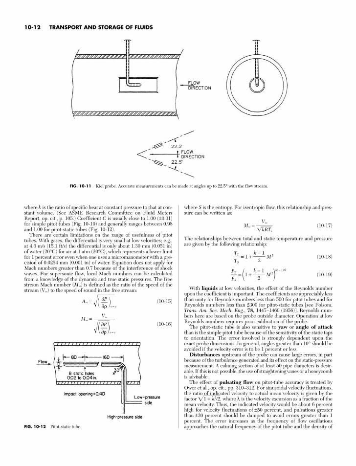
where k is the ratio of specific heat at constant pressure to that at con-stant volume. (See ASME Research Committee on Fluid MetersReport, op. cit., p. 105.) Coefficient C is usually close to 1.00 (±0.01)for simple pitot tubes (Fig. 10-10) and generally ranges between 0.98and 1.00 for pitot-static tubes (Fig. 10-12).
There are certain limitations on the range of usefulness of pitottubes. With gases, the differential is very small at low velocities; e.g.,at 4.6 m/s (15.1 ft/s) the differential is only about 1.30 mm (0.051 in)of water (20°C) for air at 1 atm (20°C), which represents a lower limitfor 1 percent error even when one uses a micromanometer with a pre-cision of 0.0254 mm (0.001 in) of water. Equation does not apply forMach numbers greater than 0.7 because of the interference of shockwaves. For supersonic flow, local Mach numbers can be calculatedfrom a knowledge of the dynamic and true static pressures. The freestream Mach number (M∞) is defined as the ratio of the speed of thestream (V∞) to the speed of sound in the free stream:
A∞ = s = c
(10-15)
M∞ =(10-16)
V∞
∂∂Pρ
s = c
∂P∂ρ
where S is the entropy. For isentropic flow, this relationship and pres-sure can be written as:
M∞ = (10-17)
The relationships between total and static temperature and pressureare given by the following relationship:
= 1 + M 2 (10-18)
= 1 + M 2(k − 1)/k
(10-19)
With liquids at low velocities, the effect of the Reynolds numberupon the coefficient is important. The coefficients are appreciably lessthan unity for Reynolds numbers less than 500 for pitot tubes and forReynolds numbers less than 2300 for pitot-static tubes [see Folsom,Trans. Am. Soc. Mech. Eng., 78, 1447–1460 (1956)]. Reynolds num-bers here are based on the probe outside diameter. Operation at lowReynolds numbers requires prior calibration of the probe.
The pitot-static tube is also sensitive to yaw or angle of attackthan is the simple pitot tube because of the sensitivity of the static tapsto orientation. The error involved is strongly dependent upon theexact probe dimensions. In general, angles greater than 10° should beavoided if the velocity error is to be 1 percent or less.
Disturbances upstream of the probe can cause large errors, in partbecause of the turbulence generated and its effect on the static-pressuremeasurement. A calming section of at least 50 pipe diameters is desir-able. If this is not possible, the use of straightening vanes or a honeycombis advisable.
The effect of pulsating flow on pitot-tube accuracy is treated byOwer et al., op. cit., pp. 310–312. For sinusoidal velocity fluctuations,the ratio of indicated velocity to actual mean velocity is given by thefactor 1 + λ22, where λ is the velocity excursion as a fraction of themean velocity. Thus, the indicated velocity would be about 6 percenthigh for velocity fluctuations of ±50 percent, and pulsations greaterthan ±20 percent should be damped to avoid errors greater than 1percent. The error increases as the frequency of flow oscillationsapproaches the natural frequency of the pitot tube and the density of
k − 1
2PTPS
k − 1
2TTTS
V∞kRTs
10-12 TRANSPORT AND STORAGE OF FLUIDS
FIG. 10-11 Kiel probe. Accurate measurements can be made at angles up to 22.5° with the flow stream.
FIG. 10-12 Pitot-static tube.
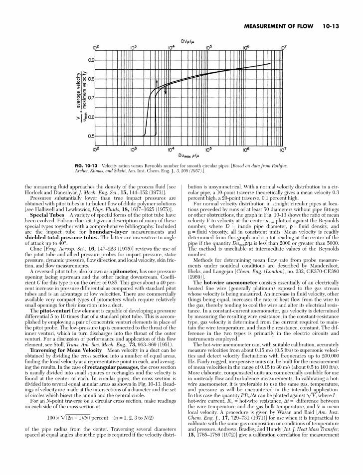
the measuring fluid approaches the density of the process fluid [seeHorlock and Daneshyar, J. Mech. Eng. Sci., 15, 144–152 (1973)].
Pressures substantially lower than true impact pressures areobtained with pitot tubes in turbulent flow of dilute polymer solutions[see Halliwell and Lewkowicz, Phys. Fluids, 18, 1617–1625 (1975)].
Special Tubes A variety of special forms of the pitot tube havebeen evolved. Folsom (loc. cit.) gives a description of many of thesespecial types together with a comprehensive bibliography. Includedare the impact tube for boundary-layer measurements andshielded total-pressure tubes. The latter are insensitive to angleof attack up to 40°.
Chue [Prog. Aerosp. Sci., 16, 147–223 (1975)] reviews the use ofthe pitot tube and allied pressure probes for impact pressure, staticpressure, dynamic pressure, flow direction and local velocity, skin fric-tion, and flow measurements.
A reversed pitot tube, also known as a pitometer, has one pressureopening facing upstream and the other facing downstream. Coeffi-cient C for this type is on the order of 0.85. This gives about a 40 per-cent increase in pressure differential as compared with standard pitottubes and is an advantage at low velocities. There are commerciallyavailable very compact types of pitometers which require relativelysmall openings for their insertion into a duct.
The pitot-venturi flow element is capable of developing a pressuredifferential 5 to 10 times that of a standard pitot tube. This is accom-plished by employing a pair of concentric venturi elements in place ofthe pitot probe. The low-pressure tap is connected to the throat of theinner venturi, which in turn discharges into the throat of the outerventuri. For a discussion of performance and application of this flowelement, see Stoll, Trans. Am. Soc. Mech. Eng., 73, 963–969 (1951).
Traversing for Mean Velocity Mean velocity in a duct can beobtained by dividing the cross section into a number of equal areas,finding the local velocity at a representative point in each, and averag-ing the results. In the case of rectangular passages, the cross sectionis usually divided into small squares or rectangles and the velocity isfound at the center of each. In circular pipes, the cross section isdivided into several equal annular areas as shown in Fig. 10-13. Read-ings of velocity are made at the intersections of a diameter and the setof circles which bisect the annuli and the central circle.
For an N-point traverse on a circular cross section, make readingson each side of the cross section at
100 × (2n − 1)/N) percent (n = 1, 2, 3 to N/2)
of the pipe radius from the center. Traversing several diametersspaced at equal angles about the pipe is required if the velocity distri-
bution is unsymmetrical. With a normal velocity distribution in a cir-cular pipe, a 10-point traverse theoretically gives a mean velocity 0.3percent high; a 20-point traverse, 0.1 percent high.
For normal velocity distribution in straight circular pipes at loca-tions preceded by runs of at least 50 diameters without pipe fittingsor other obstructions, the graph in Fig. 10-13 shows the ratio of meanvelocity V to velocity at the center umax plotted against the Reynoldsnumber, where D = inside pipe diameter, ρ = fluid density, andµ = fluid viscosity, all in consistent units. Mean velocity is readilydetermined from this graph and a pitot reading at the center of thepipe if the quantity Dumaxρµ is less than 2000 or greater than 5000.The method is unreliable at intermediate values of the Reynoldsnumber.
Methods for determining mean flow rate from probe measure-ments under nonideal conditions are described by Mandersloot,Hicks, and Langejan [Chem. Eng. (London), no. 232, CE370-CE380(1969)].
The hot-wire anemometer consists essentially of an electricallyheated fine wire (generally platinum) exposed to the gas streamwhose velocity is being measured. An increase in fluid velocity, otherthings being equal, increases the rate of heat flow from the wire tothe gas, thereby tending to cool the wire and alter its electrical resis-tance. In a constant-current anemometer, gas velocity is determinedby measuring the resulting wire resistance; in the constant-resistancetype, gas velocity is determined from the current required to main-tain the wire temperature, and thus the resistance, constant. The dif-ference in the two types is primarily in the electric circuits andinstruments employed.
The hot-wire anemometer can, with suitable calibration, accuratelymeasure velocities from about 0.15 m/s (0.5 ft/s) to supersonic veloci-ties and detect velocity fluctuations with frequencies up to 200,000Hz. Fairly rugged, inexpensive units can be built for the measurementof mean velocities in the range of 0.15 to 30 m/s (about 0.5 to 100 ft/s).More elaborate, compensated units are commercially available for usein unsteady flow and turbulence measurements. In calibrating a hot-wire anemometer, it is preferable to use the same gas, temperature,and pressure as will be encountered in the intended application. In this case the quantity I2Rw∆t can be plotted against V, where I =hot-wire current, Rw = hot-wire resistance, ∆t = difference betweenthe wire temperature and the gas bulk temperature, and V = meanlocal velocity. A procedure is given by Wasan and Baid [Am. Inst.Chem. Eng. J., 17, 729–731 (1971)] for use when it is impractical tocalibrate with the same gas composition or conditions of temperatureand pressure. Andrews, Bradley, and Hundy [Int. J. Heat Mass Transfer,15, 1765–1786 (1972)] give a calibration correlation for measurement
MEASUREMENT OF FLOW 10-13
FIG. 10-13 Velocity ration versus Reynolds number for smooth circular pipes. [Based on data from Rothfus,Archer, Klimas, and Sikchi, Am. Inst. Chem. Eng. J., 3, 208 (1957).]
of small gas velocities. The hot-wire anemometer is treated in consid-erable detail in Dean, op. cit., chap. VI; in Ladenburg et al., op. cit.,art. F-2; by Grant and Kronauer, Symposium on Measurement inUnsteady Flow, American Society of Mechanical Engineers, NewYork, 1962, pp. 44–53; ASME Research Committee on Fluid MetersReport, op. cit., pp. 105–107; and by Compte-Bellot, Ann. Rev. FluidMech., 8, pp. 209–231 (1976).
The hot-wire anemometer can be modified for liquid measure-ments, although difficulties are encountered because of bubbles anddirt adhering to the wire. See Stevens, Borden, and Strausser, DavidTaylor Model Basin Rep. 953, December 1956; Middlebrook andPiret, Ind. Eng. Chem., 42, 1511–1513 (1950); and Piret et al., Ind.Eng. Chem., 39, 1098–1103 (1947).
The hot-film anemometer has been developed for applications inwhich use of the hot-wire anemometer presents problems. It consistsof a platinum-film sensing element deposited on a glass substrate. Var-ious geometries can be used. The most common involves a wedge witha 30° included angle at the end of a tapered rod. The wedge is com-monly 1 mm (0.039 in) long and 0.2 mm (0.0079 in) wide on each face.Compared with the hot wire, it is less susceptible to fouling by bub-bles or dirt when used in liquids, has greater mechanical strengthwhen used with gases at high velocities and high temperatures, andcan give a higher signal-to-noise ratio. For additional information seeLing and Hubbard, J. Aeronaut. Sci., 23, 890–891 (1956); and Ling, J.Basic Eng., 82, 629–634 (1960).
The heated-thermocouple anemometer measures gas velocityfrom the cooling effect of the gas stream flowing across the hotjunctions of a thermopile supplied with constant electrical powerinput. Alternate junctions are maintained at ambient temperature,thus compensating for the effect of ambient temperature. Fordetails see Bunker, Proc. Instrum. Soc. Am., 9, pap. 54-43-2 (1954).
A glass-coated bead thermistor anemometer can be used for themeasurement of low fluid velocities, down to 0.001 m/s (0.003 ft/s) inair and 0.0002 m/s (0.0007 ft/s) in water [see Murphy and Sparks, Ind.Eng. Chem. Fundam., 7, 642–645 (1968)].
The laser-Doppler anemometer measures local fluid velocityfrom the change in frequency of radiation, between a stationarysource and a receiver, due to scattering by particles along the wavepath. A laser is commonly used as the source of incident illumina-tion. The measurements are essentially independent of local tem-perature and pressure. This technique can be used in many differentflow systems with transparent fluids containing particles whosevelocity is actually measured. For a brief review of the laser-Dopplertechnique see Goldstein, Appl. Mech. Rev., 27, 753–760 (1974). Foradditional details see Durst, Melling, and Whitelaw, Principles andPractice of Laser-Doppler Anemometry, Academic, New York, 1976.
FLOWMETERS
In the process industries, flow measurement devices are the largestmarket in the process instrumentation field. Two web sites forprocess equipment and instrumentation, www.globalspec.com, andwww.thomasnet.com, both list more than 800 companies that offer flowmeasurement products. There are more than one hundred types offlowmeters commercially available. The aforementioned web sites notonly facilitate selection and specification of commercial flowmeters, butalso provide electronic access to manufacturers’ technical literature.
Devices that measure flow can be categorized in two areas as fol-lows:
1. All types of measuring devices in which the material passes with-out being divided into isolated quantities. Movement of the material isusually sensed by a primary measuring element which activates a sec-ondary device. The flow rate is then inferred from the response of thesecondary device by means of known physical laws or from empiricalrelationships.
2. A positive-displacement meter, which applies to a device inwhich the flow is divided into isolated measured volumes. The num-ber of fillings of these known volumes are measured with respect totime.
The most common application of flow measurement in processplants is flow in pipes, ducts, and tubing. Table 10-4 lists widely used
flowmeters for these closed conduits as well as the two major classesof open-channel flowmeters. Table 10-4 also lists many other types offlowmeters that are discussed later in this subsection.
This subsection summarizes selection and installation of flowme-ters, including the measurement of pressure and velocities of fluidswhen the flow measurement technique requires it.
INDUSTRY GUIDELINES AND STANDARDS
Because flow measurement is important, many engineering societiesand trade organizations have developed flow-related guidelines, stan-dards, and other publications (Table 10-5). The reader should consultthe appropriate standards when specifying, installing, and calibratingflow measurement systems.
There are also numerous articles in scholarly journals, trade maga-zines, and manufacturers’ literature related to flow measurement.
Different types of flowmeters differ markedly in their degrees ofsensitivity to flow disturbances. In the most extreme cases, obtaininghighly accurate flow measurements with certain types of flowmetersmay require 60D upstream straight pipe and 20D downstream. Valvescan be particularly problematic because their effects on a flowmetervary with valve position. Numerous types of flow straighteners or con-ditioners, as shown in Fig. 10-9, can significantly reduce the requiredrun of straight pipe upstream of a given flowmeter.
CLASSIFICATION OF FLOWMETERS
Table 10-4 lists the major classes of flowmeters, along with commonexamples of each. Brief descriptions are provided in this subsection,followed by more details in subsequent subsections.
Differential Pressure Meters Differential pressure metersor head meters measure the change in pressure across a special flowelement. The differential pressure increases with increasing flowrate. The pitot tubes described previously work on this principle.Other examples include orifices [see also Eqs. (6-111) and (8-102),and Fig. 10-14], nozzles (Fig. 10-19), targets, venturis (see also Sec.8 and Fig. 10-17), and elbow meters. Averaging pitot tubes producea pressure differential that is based on multiple measuring pointsacross the flow path.
Differential pressure meters are widely used. Temperature, pres-sure, and density affect gas density and readings of differential pres-sure meters. For that reason, many commercial flowmeters that arebased on measurement of differential pressure often have integraltemperature and absolute pressure measurements in addition to dif-ferential pressure. They also frequently have automatic temperatureand pressure compensation.
Velocity Meters Velocity meters measure fluid velocity. Exam-ples include electromagnetic, propeller, turbine, ultrasonic Doppler,ultrasonic transit time, and vortex meters. Section 8 describes theprinciples of operation of electromagnetic, turbine, ultrasonic, andvortex flowmeters.
Mass Meters Mass flowmeters measure the rate of mass flowthrough a conduit. Examples include Coriolis flowmeters and thermalmass flowmeters. Coriolis flowmeters can measure fluid densitysimultaneously with mass flow rate. This permits calculation of volu-metric flow rate as well. Section 8 includes brief descriptions of Cori-olis and thermal mass flowmeters.
Volumetric Meters Volumetric meters (also called positive-displacement flowmeters) are devices that mechanically divide afluid stream into discrete, known volumes and count the number ofvolumes that pass through the device. See Spitzer (2005, op. cit.).
Variable-Area Meters Variable-area meters, which are alsocalled rotameters, offer popular and inexpensive flow measurementdevices. These meters employ a float inside a tube that has an inter-nal cross-sectional area that increases with distance upward in theflow path through the tube. As the flow rate increases, the float risesin the tube to provide a larger area for the flowing fluid to pass.
Open-Channel Flow Measurement Open-channel flow mea-surements are usually based on measurement of liquid level in a flowchannel constructed of a specified geometry. The two most commonflow channels used are weirs and flumes. See Spitzer (2005, op. cit.).
10-14 TRANSPORT AND STORAGE OF FLUIDS
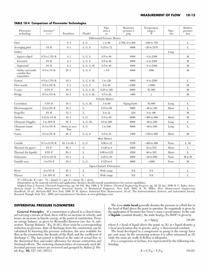
MEASUREMENT OF FLOW 10-15
DIFFERENTIAL PRESSURE FLOWMETERS
General Principles If a constriction is placed in a closed chan-nel carrying a stream of fluid, there will be an increase in velocity, andhence an increase in kinetic energy, at the point of constriction. Froman energy balance, as given by Bernoulli’s theorem [see Sec. 6, sub-section “Energy Balance,” Eq. (6-16)], there must be a correspondingreduction in pressure. Rate of discharge from the constriction can becalculated by knowing this pressure reduction, the area available forflow at the constriction, the density of the fluid, and the coefficient ofdischarge C. The last-named is defined as the ratio of actual flow tothe theoretical flow and makes allowance for stream contraction andfrictional effects. The metering characteristics of commonly used dif-ferential pressure meters are reviewed and grouped by Halmi [J. Flu-ids Eng., 95, 127–141 (1973)].
The term static head generally denotes the pressure in a fluid due tothe head of fluid above the point in question. Its magnitude is given bythe application of Newton’s law (force = mass × acceleration). In the caseof liquids (constant density), the static head ph Pa (lbf/ft2) is given by
ph = hρggc (10-20)
where h = head of liquid above the point, m (ft); ρ = liquid density; g= local acceleration due to gravity; and gc = dimensional constant.
The head developed in a compressor or pump is the energy forceper unit mass. In the measuring systems it is often misnamed as (ft)while the units are really ft-lb/lbm or kilojoules.
For a compressor or turbine, it is represented by the following rela-tionship:
E = U1Vθ1 − U2Vθ2 (10-21)
TABLE 10-4 Comparison of Flowmeter Technologies
Pipe Maximum Temperature RelativeFlowmeter Accuracy* sizes,‡ pressure,‡ range,‡ Pipe pressuretechnology (+/–) Turndown Fluids† in psig oF run loss
Differential Pressure Meters
Pitot 8 :1 L, G 1 to 96 2.76E-4 to 200 −200 to 750 L
Averaging pitot 1% R 8 :1 L, G, S 0.25 to 72 8800 −20 to 2370 L
Orifice Long
Square-edged 0.5 to 1.5% R 4 :1 L, G, S 0.5 to 40 8800 −4 to 2300 M
Eccentric 2% R 4 :1 L, G, S 0.5 to 40 8800 −4 to 2300 M
Segmental 2% R 4 :1 L, G, S, SL 0.5 to 40 8800 −4 to 2300 M
Orifice and multi- 0.5 to 1% R 10 :1 L, G, S > 0.5 4000 1000 Mvariable flowtransmitter
Venturi 0.5 to 1.5% R 10 :1 L, G, S, SL 1 to 120 8800 −4 to 2300 L
Flow nozzle 0.5 to 2% R 8 :1 L, G, S 2 to 80 >1000 <1000 M
V cone 0.5% F 10 :1 L, G, S, SL 0.25 to 120 6000 To 400 M
Wedge 0.5 to 5% R 10 :1 L, G, S, SL 0.5 to 24 >600 ‡ M
Velocity Meters
Correlation 0.5% R 10 :1 L, G, SL 1 to 60 Piping limits To 600 Long L
Electromagnetic 0.2 to 2% R 10 :1 L 0.15 to 60 5000 −40 to 350 Short L
Propeller 2% R 15 :1 L 2 to 12 230 0 to 300 M
Turbine 0.15 to 1% R 10 :1 L, G 0.5 to 30 6000 −450 to 600 Short M
Ultrasonic Doppler 1 to 30% R 50 :1 L, G, SL 0.5 to 200 6000 −40 to 250 Long L
Ultrasonic transit 0.5 to 5% R Down to zero L, G 1 to 540 6000 −40 to 650 Long Ltime flow
Vortex 0.5 to 2% R 20 :1 L, G, S 0.5 to 16 1500 −330 to 800 Short M
Mass Meters
Coriolis 0.1 to 0.3% R 10 :1 to 80 :1 L, G 0.06 to 12 5700 −400 to 800 None L, M
Thermal (for gases) 1% F 50 :1 G 0.125 to 8 4500 32 to 572 Short L
Thermal (for liquids) 0.5% F 50 :1 L 0.06 to 0.25 4500 40 to 165 Short L
Volumetric 0.15 to 2% R 10 :1 L 0.25 to 16 2000 −40 to 600 None M to H
Variable area 1 to 5% F 10 :1 L, G 0.125 to 6 6000 <1000 None M
Open-Channel Flowmeters
Weirs 2 to 5% R 25 :1 L Wide range NA NA L
Flumes 3 to 10% R 40 :1 L Wide range NA NA L
*F = full scale, R = rate. †L = liquid, G = gas, S = steam, SL = slurry.‡Dependent on the material selection and application. Readers should consult manufacturers for current capabilities.Adapted from J. Pomroy, Chemical Engineering, pp. 94–102, May 1996; J. W. Dolenc, Chemical Engineering Progress, pp. 22–32, Jan. 1996; R. C. Baker, Intro-
ductory Guide to Flow Measurement, American Society of Mechanical Engineers, New York, 2003; R. W. Miller, Flow Measurement EngineeringHandbook, 3d ed., McGraw-Hill, New York, 1996; D. W. Spitzer, Industrial Flow Measurement, 3d ed., The Instrumentation, Systems, and Automation Society,Research Triangle Park, N.C., 2005; and manufacturers’ literature at www.globalspec.com.
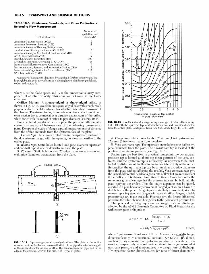
where U is the blade speed and Vθ is the tangential velocity com-ponent of absolute velocity. This equation is known as the Eulerequation.
Orifice Meters A square-edged or sharp-edged orifice, asshown in Fig. 10-14, is a clean-cut square-edged hole with straight wallsperpendicular to the flat upstream face of a thin plate placed crosswise ofthe channel. The stream issuing from such an orifice attains its minimumcross section (vena contracta) at a distance downstream of the orificewhich varies with the ratio β of orifice to pipe diameter (see Fig. 10-15).
For a centered circular orifice in a pipe, the pressure differential iscustomarily measured between one of the following pressure-tappairs. Except in the case of flange taps, all measurements of distancefrom the orifice are made from the upstream face of the plate.
1. Corner taps. Static holes drilled one in the upstream and one inthe downstream flange, with the openings as close as possible to theorifice plate.
2. Radius taps. Static holes located one pipe diameter upstreamand one-half pipe diameter downstream from the plate.
3. Pipe taps. Static holes located 21⁄2 pipe diameters upstream andeight pipe diameters downstream from the plate.
4. Flange taps. Static holes located 25.4 mm (1 in) upstream and25.4 mm (1 in) downstream from the plate.
5. Vena-contracta taps. The upstream static hole is one-half to twopipe diameters from the plate. The downstream tap is located at theposition of minimum pressure (see Fig. 10-15).
Radius taps are best from a practical standpoint; the downstreampressure tap is located at about the mean position of the vena con-tracta, and the upstream tap is sufficiently far upstream to be unaf-fected by distortion of the flow in the immediate vicinity of the orifice(in practice, the upstream tap can be as much as two pipe diametersfrom the plate without affecting the results). Vena-contracta taps givethe largest differential head for a given rate of flow but are inconvenientif the orifice size is changed from time to time. Corner taps offer thesometimes great advantage that the pressure taps can be built into theplate carrying the orifice. Thus the entire apparatus can be quicklyinserted in a pipe line at any convenient flanged joint without having todrill holes in the pipe. Flange taps are similarly convenient, since bymerely replacing standard flanges with special orifice flanges, suitablepressure taps are made available. Pipe taps give the lowest differentialpressure, the value obtained being close to the permanent pressure loss.
The practical working equation for weight rate of discharge,adopted by the ASME Research Committee on Fluid Meters for usewith either gases or liquids, is
w = q1ρ1 = CYA2 = KYA2 2gc(p1− p2)ρ1 (10-22)
where A2 = cross-sectional area of throat; C = coefficient of discharge,dimensionless; gc = dimensional constant; K = C1 − β4, dimen-sionless; p1, p2 = pressure at upstream and downstream static pres-sure taps respectively; q1 = volumetric rate of discharge measured atupstream pressure and temperature; w = weight rate of discharge; Y = expansion factor, dimensionless; β = ratio of throat diameter to
2gc(p1 − p2)ρ1
1 − β4
10-16 TRANSPORT AND STORAGE OF FLUIDS
TABLE 10-5 Guidelines, Standards, and Other PublicationsRelated to Flow Measurement
Number ofguidelines and
Technical society standards*
American Gas Association (AGA) 2American Petroleum Institute (API) 11American Society of Heating, Refrigeration, and Air Conditioning Engineers (ASHRAE) 5
American Society of Mechanical Engineers (ASME) 18ASTM International (ASTM) 17British Standards Institution (BSI) 100Deutsches Institut fur Normung E. V. (DIN) 48International Electrotechnical Commission (IEC) 6Instrumentation, Systems, and Automation Society (ISA) 3International Organization for Standardization (ISO) 212SAE International (SAE) 6
*Number of documents identified by searching for flow measurement onhttp://global.ihs.com, the web site of a clearinghouse of industry guidelines,codes, and standards.
(a)
(b)
FIG. 10-14 Square-edged or sharp-edged orifices. The plate at the orificeopening must not be thicker than one-thirtieth of the pipe diameter, one-eighthof the orifice diameter, or one-fourth of the distance from the pipe wall to theedge of the opening. (a) Pipe-line orifice. (b) Types of plates.
FIG. 10-15 Coefficient of discharge for square-edged circular orifices for NRe
> 30,000 with the upstream tap located between one and two pipe diametersfrom the orifice plate. [Spitzglass, Trans. Am. Soc. Mech. Eng., 44, 919 (1922).]
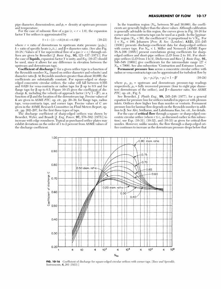
pipe diameter, dimensionless; and ρ1 = density at upstream pressureand temperature.
For the case of subsonic flow of a gas (rc < r < 1.0), the expansionfactor Y for orifices is approximated by
Y = 1 − [(1 − r)k](0.41 + 0.35β4) (10-23)
where r = ratio of downstream to upstream static pressure (p2/p1),k = ratio of specific heats (cp/cv), and β = diameter ratio. (See also Fig.10-18.) Values of Y for supercritical flow of a gas (r < rc) through ori-fices are given by Benedict [J. Basic Eng., 93, 121–137 (1971)]. Forthe case of liquids, expansion factor Y is unity, and Eq. (10-27) shouldbe used, since it allows for any difference in elevation between theupstream and downstream taps.
Coefficient of discharge C for a given orifice type is a function ofthe Reynolds number NRe (based on orifice diameter and velocity) anddiameter ratio β. At Reynolds numbers greater than about 30,000, thecoefficients are substantially constant. For square-edged or sharp-edged concentric circular orifices, the value will fall between 0.595and 0.620 for vena-contracta or radius taps for β up to 0.8 and forflange taps for β up to 0.5. Figure 10-15 gives the coefficient of dis-charge K, including the velocity-of-approach factor (11 − β4), as afunction of β and the location of the downstream tap. Precise values ofK are given in ASME PTC, op. cit., pp. 20–39, for flange taps, radiustaps, vena-contracta taps, and corner taps. Precise values of C aregiven in the ASME Research Committee on Fluid Meters Report, op.cit., pp. 202–207, for the first three types of taps.
The discharge coefficient of sharp-edged orifices was shown byBenedict, Wyler, and Brandt [J. Eng. Power, 97, 576–582 (1975)] toincrease with edge roundness. Typical as-purchased orifice plates mayexhibit deviations on the order of 1 to 2 percent from ASME values ofthe discharge coefficient.
In the transition region (NRe between 50 and 30,000), the coeffi-cients are generally higher than the above values. Although calibrationis generally advisable in this region, the curves given in Fig. 10-16 forcorner and vena-contracta taps can be used as a guide. In the laminar-flow region (NRe < 50), the coefficient C is proportional to NRe. For1 < NRe < 100, Johansen [Proc. R. Soc. (London), A121, 231–245(1930)] presents discharge-coefficient data for sharp-edged orificeswith corner taps. For NRe < 1, Miller and Nemecek [ASME Paper 58-A-106 (1958)] present correlations giving coefficients for sharp-edged orifices and short-pipe orifices (L/D from 2 to 10). For short-pipe orifices (L/D from 1 to 4), Dickerson and Rice [ J. Basic Eng., 91,546–548 (1969)] give coefficients for the intermediate range (27 <NRe < 7000). See also subsection “Contraction and Entrance Losses.”
Permanent pressure loss across a concentric circular orifice withradius or vena-contracta taps can be approximated for turbulent flow by
(p1 − p4)(p1 − p2) = 1 − β2 (10-24)
where p1, p2 = upstream and downstream pressure-tap readingsrespectively, p4 = fully recovered pressure (four to eight pipe diame-ters downstream of the orifice), and β = diameter ratio. See ASMEPTC, op. cit., Fig. 5.
See Benedict, J. Fluids Eng., 99, 245–248 (1977), for a generalequation for pressure loss for orifices installed in pipes or with plenuminlets. Orifices show higher loss than nozzles or venturis. Permanentpressure loss for laminar flow depends on the Reynolds number in addi-tion to β. See Alvi, Sridharan, and Lakshmana Rao, loc. cit., for details.
For the case of critical flow through a square- or sharp-edged con-centric circular orifice (where r ≤ rc, as discussed earlier in this subsec-tion), use Eqs. (10-31), (10-32), and (10-33) as given for critical-flownozzles. However, unlike nozzles, the flow through a sharp-edged ori-fice continues to increase as the downstream pressure drops below that
MEASUREMENT OF FLOW 10-17
FIG. 10-16 Coefficient of discharge for square-edged circular orifices with corner taps. [Tuve and Sprenkle,Instruments, 6, 201 (1933).]
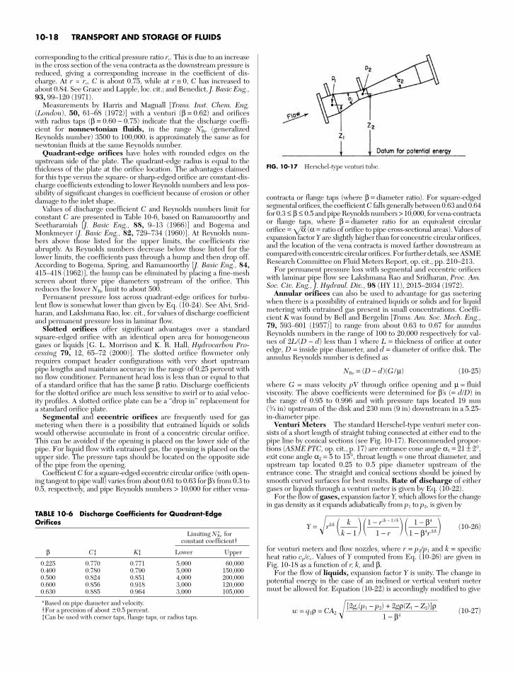
corresponding to the critical pressure ratio rc. This is due to an increasein the cross section of the vena contracta as the downstream pressure isreduced, giving a corresponding increase in the coefficient of dis-charge. At r = rc, C is about 0.75, while at r ≅ 0, C has increased toabout 0.84. See Grace and Lapple, loc. cit.; and Benedict, J. Basic Eng.,93, 99–120 (1971).
Measurements by Harris and Magnall [Trans. Inst. Chem. Eng.(London), 50, 61–68 (1972)] with a venturi (β = 0.62) and orificeswith radius taps (β = 0.60 − 0.75) indicate that the discharge coeffi-cient for nonnewtonian fluids, in the range N′Re (generalizedReynolds number) 3500 to 100,000, is approximately the same as fornewtonian fluids at the same Reynolds number.
Quadrant-edge orifices have holes with rounded edges on theupstream side of the plate. The quadrant-edge radius is equal to thethickness of the plate at the orifice location. The advantages claimedfor this type versus the square- or sharp-edged orifice are constant-dis-charge coefficients extending to lower Reynolds numbers and less pos-sibility of significant changes in coefficient because of erosion or otherdamage to the inlet shape.
Values of discharge coefficient C and Reynolds numbers limit forconstant C are presented in Table 10-6, based on Ramamoorthy andSeetharamiah [J. Basic Eng., 88, 9–13 (1966)] and Bogema andMonkmeyer (J. Basic Eng., 82, 729–734 (1960)]. At Reynolds num-bers above those listed for the upper limits, the coefficients riseabruptly. As Reynolds numbers decrease below those listed for thelower limits, the coefficients pass through a hump and then drop off.According to Bogema, Spring, and Ramamoorthy [J. Basic Eng., 84,415–418 (1962)], the hump can be eliminated by placing a fine-meshscreen about three pipe diameters upstream of the orifice. Thisreduces the lower NRe limit to about 500.
Permanent pressure loss across quadrant-edge orifices for turbu-lent flow is somewhat lower than given by Eq. (10-24). See Alvi, Srid-haran, and Lakshmana Rao, loc. cit., for values of discharge coefficientand permanent pressure loss in laminar flow.
Slotted orifices offer significant advantages over a standardsquare-edged orifice with an identical open area for homogeneousgases or liquids [G. L. Morrison and K. R. Hall, Hydrocarbon Pro-cessing 79, 12, 65–72 (2000)]. The slotted orifice flowmeter onlyrequires compact header configurations with very short upstreampipe lengths and maintains accuracy in the range of 0.25 percent withno flow conditioner. Permanent head loss is less than or equal to thatof a standard orifice that has the same β ratio. Discharge coefficientsfor the slotted orifice are much less sensitive to swirl or to axial veloc-ity profiles. A slotted orifice plate can be a “drop in” replacement fora standard orifice plate.
Segmental and eccentric orifices are frequently used for gasmetering when there is a possibility that entrained liquids or solidswould otherwise accumulate in front of a concentric circular orifice.This can be avoided if the opening is placed on the lower side of thepipe. For liquid flow with entrained gas, the opening is placed on theupper side. The pressure taps should be located on the opposite sideof the pipe from the opening.
Coefficient C for a square-edged eccentric circular orifice (with open-ing tangent to pipe wall) varies from about 0.61 to 0.63 for β’s from 0.3 to0.5, respectively, and pipe Reynolds numbers > 10,000 for either vena-
contracta or flange taps (where β = diameter ratio). For square-edgedsegmental orifices, the coefficient C falls generally between 0.63 and 0.64for 0.3 ≤ β ≤ 0.5 and pipe Reynolds numbers > 10,000, for vena-contractaor flange taps, where β = diameter ratio for an equivalent circularorifice = α (α = ratio of orifice to pipe cross-sectional areas). Values ofexpansion factor Y are slightly higher than for concentric circular orifices,and the location of the vena contracta is moved farther downstream ascompared with concentric circular orifices. For further details, see ASMEResearch Committee on Fluid Meters Report, op. cit., pp. 210–213.
For permanent pressure loss with segmental and eccentric orificeswith laminar pipe flow see Lakshmana Rao and Sridharan, Proc. Am.Soc. Civ. Eng., J. Hydraul. Div., 98 (HY 11), 2015–2034 (1972).
Annular orifices can also be used to advantage for gas meteringwhen there is a possibility of entrained liquids or solids and for liquidmetering with entrained gas present in small concentrations. Coeffi-cient K was found by Bell and Bergelin [Trans. Am. Soc. Mech. Eng.,79, 593–601 (1957)] to range from about 0.63 to 0.67 for annulusReynolds numbers in the range of 100 to 20,000 respectively for val-ues of 2L/(D − d) less than 1 where L = thickness of orifice at outeredge, D = inside pipe diameter, and d = diameter of orifice disk. Theannulus Reynolds number is defined as
NRe = (D − d)(G /µ) (10-25)
where G = mass velocity pV through orifice opening and µ = fluidviscosity. The above coefficients were determined for β’s (= d/D) inthe range of 0.95 to 0.996 and with pressure taps located 19 mm(3⁄4 in) upstream of the disk and 230 mm (9 in) downstream in a 5.25-in-diameter pipe.
Venturi Meters The standard Herschel-type venturi meter con-sists of a short length of straight tubing connected at either end to thepipe line by conical sections (see Fig. 10-17). Recommended propor-tions (ASME PTC, op. cit., p. 17) are entrance cone angle α1 = 21 ± 2°,exit cone angle α2 = 5 to 15°, throat length = one throat diameter, andupstream tap located 0.25 to 0.5 pipe diameter upstream of theentrance cone. The straight and conical sections should be joined bysmooth curved surfaces for best results. Rate of discharge of eithergases or liquids through a venturi meter is given by Eq. (10-22).
For the flow of gases, expansion factor Y, which allows for the changein gas density as it expands adiabatically from p1 to p2, is given by
Y = r2/k (10-26)
for venturi meters and flow nozzles, where r = p2/p1 and k = specificheat ratio cp/cv. Values of Y computed from Eq. (10-26) are given inFig. 10-18 as a function of r, k, and β.
For the flow of liquids, expansion factor Y is unity. The change inpotential energy in the case of an inclined or vertical venturi metermust be allowed for. Equation (10-22) is accordingly modified to give
w = q1ρ = CA2 (10-27)[2gc(p1 − p2) + 2gρ(Z1 − Z2)]ρ
1 − β4
1 − β4
1 − β4r 2/k
1 − r(k − 1)/k
1 − r
kk − 1
10-18 TRANSPORT AND STORAGE OF FLUIDS
TABLE 10-6 Discharge Coefficients for Quadrant-EdgeOrifices
Limiting NRe* forconstant coefficient†
β C‡ K‡ Lower Upper
0.225 0.770 0.771 5,000 60,0000.400 0.780 0.790 5,000 150,0000.500 0.824 0.851 4,000 200,0000.600 0.856 0.918 3,000 120,0000.630 0.885 0.964 3,000 105,000
*Based on pipe diameter and velocity.†For a precision of about 0.5 percent.‡Can be used with corner taps, flange taps, or radius taps.
FIG. 10-17 Herschel-type venturi tube.
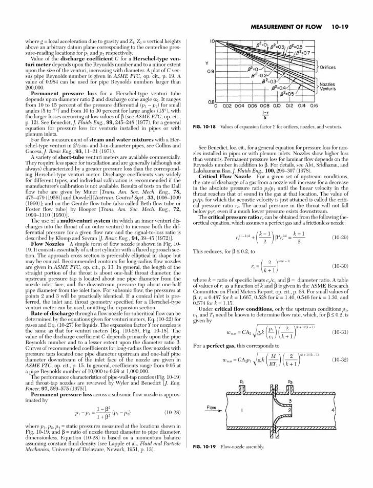
where g = local acceleration due to gravity and Z1, Z2 = vertical heightsabove an arbitrary datum plane corresponding to the centerline pres-sure-reading locations for p1 and p2 respectively.
Value of the discharge coefficient C for a Herschel-type ven-turi meter depends upon the Reynolds number and to a minor extentupon the size of the venturi, increasing with diameter. A plot of C ver-sus pipe Reynolds number is given in ASME PTC, op. cit., p. 19. Avalue of 0.984 can be used for pipe Reynolds numbers larger than200,000.
Permanent pressure loss for a Herschel-type venturi tubedepends upon diameter ratio β and discharge cone angle α2. It rangesfrom 10 to 15 percent of the pressure differential (p1 − p2) for smallangles (5 to 7°) and from 10 to 30 percent for large angles (15°), withthe larger losses occurring at low values of β (see ASME PTC, op. cit.,p. 12). See Benedict, J. Fluids Eng., 99, 245–248 (1977), for a generalequation for pressure loss for venturis installed in pipes or withplenum inlets.
For flow measurement of steam and water mixtures with a Her-schel-type venturi in 21⁄2-in- and 3-in-diameter pipes, see Collins andGacesa, J. Basic Eng., 93, 11–21 (1971).
A variety of short-tube venturi meters are available commercially.They require less space for installation and are generally (although notalways) characterized by a greater pressure loss than the correspond-ing Herschel-type venturi meter. Discharge coefficients vary widelyfor different types, and individual calibration is recommended if themanufacturer’s calibration is not available. Results of tests on the Dallflow tube are given by Miner [Trans. Am. Soc. Mech. Eng., 78,475–479 (1956)] and Dowdell [Instrum. Control Syst., 33, 1006–1009(1960)]; and on the Gentile flow tube (also called Beth flow tube orFoster flow tube) by Hooper [Trans. Am. Soc. Mech. Eng., 72,1099–1110 (1950)].
The use of a multiventuri system (in which an inner venturi dis-charges into the throat of an outer venturi) to increase both the dif-ferential pressure for a given flow rate and the signal-to-loss ratio isdescribed by Klomp and Sovran [J. Basic Eng., 94, 39–45 (1972)].
Flow Nozzles A simple form of flow nozzle is shown in Fig. 10-19. It consists essentially of a short cylinder with a flared approach sec-tion. The approach cross section is preferably elliptical in shape butmay be conical. Recommended contours for long-radius flow nozzlesare given in ASME PTC, op. cit., p. 13. In general, the length of thestraight portion of the throat is about one-half throat diameter, theupstream pressure tap is located about one pipe diameter from thenozzle inlet face, and the downstream pressure tap about one-halfpipe diameter from the inlet face. For subsonic flow, the pressures atpoints 2 and 3 will be practically identical. If a conical inlet is pre-ferred, the inlet and throat geometry specified for a Herschel-typeventuri meter can be used, omitting the expansion section.
Rate of discharge through a flow nozzle for subcritical flow can bedetermined by the equations given for venturi meters, Eq. (10-22) forgases and Eq. (10-27) for liquids. The expansion factor Y for nozzles isthe same as that for venturi meters [Eq. (10-26), Fig. 10-18]. Thevalue of the discharge coefficient C depends primarily upon the pipeReynolds number and to a lesser extent upon the diameter ratio β.Curves of recommended coefficients for long-radius flow nozzles withpressure taps located one pipe diameter upstream and one-half pipediameter downstream of the inlet face of the nozzle are given inASME PTC, op. cit., p. 15. In general, coefficients range from 0.95 ata pipe Reynolds number of 10,000 to 0.99 at 1,000,000.
The performance characteristics of pipe-wall-tap nozzles (Fig. 10-19)and throat-tap nozzles are reviewed by Wyler and Benedict [J. Eng.Power, 97, 569–575 (1975)].
Permanent pressure loss across a subsonic flow nozzle is approx-imated by
p1 − p4 = (p1 − p2) (10-28)
where p1, p2, p4 = static pressures measured at the locations shown inFig. 10-19; and β = ratio of nozzle throat diameter to pipe diameter,dimensionless. Equation (10-28) is based on a momentum balanceassuming constant fluid density (see Lapple et al., Fluid and ParticleMechanics, University of Delaware, Newark, 1951, p. 13).
1 − β2
1 + β2
See Benedict, loc. cit., for a general equation for pressure loss for noz-zles installed in pipes or with plenum inlets. Nozzles show higher lossthan venturis. Permanent pressure loss for laminar flow depends on theReynolds number in addition to β. For details, see Alvi, Sridharan, andLakshamana Rao, J. Fluids Eng., 100, 299–307 (1978).
Critical Flow Nozzle For a given set of upstream conditions,the rate of discharge of a gas from a nozzle will increase for a decreasein the absolute pressure ratio p2/p1 until the linear velocity in thethroat reaches that of sound in the gas at that location. The value ofp2/p1 for which the acoustic velocity is just attained is called the criti-cal pressure ratio rc. The actual pressure in the throat will not fallbelow p1rc even if a much lower pressure exists downstream.
The critical pressure ratio rc can be obtained from the following the-oretical equation, which assumes a perfect gas and a frictionless nozzle:
rc(1 − k)/k + β4rc
2/k = (10-29)
This reduces, for β ≤ 0.2, to
rc = k/(k − 1)
(10-30)
where k = ratio of specific heats cp/cv and β = diameter ratio. A tableof values of rc as a function of k and β is given in the ASME ResearchCommittee on Fluid Meters Report, op. cit., p. 68. For small values ofβ, rc = 0.487 for k = 1.667, 0.528 for k = 1.40, 0.546 for k = 1.30, and0.574 for k = 1.15.
Under critical flow conditions, only the upstream conditions p1,v1, and T1 need be known to determine flow rate, which, for β ≤ 0.2, isgiven by
wmax = CA2 gck(
k +
1)
/(k
−
1)
(10-31)
For a perfect gas, this corresponds to
wmax = CA2p1 gck(
k +
1)
/(k
−
1)
(10-32)2
k + 1
MRT1
2k + 1
p1v1
2k + 1
k + 1
2k − 1
2
MEASUREMENT OF FLOW 10-19
FIG. 10-18 Values of expansion factor Y for orifices, nozzles, and venturis.
FIG. 10-19 Flow-nozzle assembly.
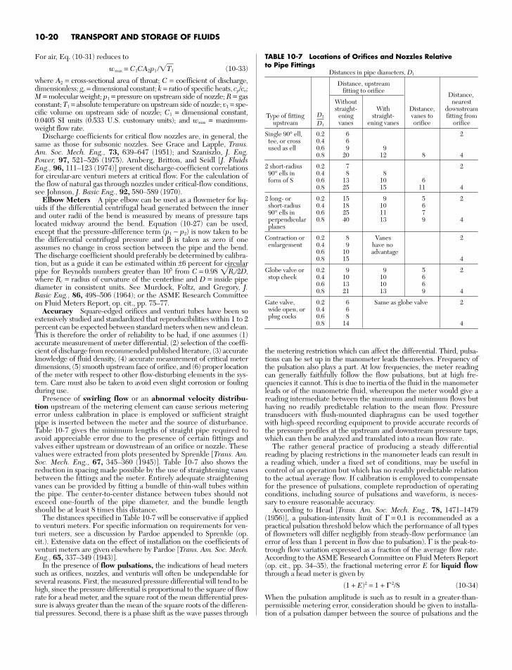
For air, Eq. (10-31) reduces to
wmax = C1CA2p1 /T1 (10-33)
where A2 = cross-sectional area of throat; C = coefficient of discharge,dimensionless; gc = dimensional constant; k = ratio of specific heats, cp/cv;M = molecular weight; p1 = pressure on upstream side of nozzle; R = gasconstant; T1 = absolute temperature on upstream side of nozzle; v1 = spe-cific volume on upstream side of nozzle; C1 = dimensional constant,0.0405 SI units (0.533 U.S. customary units); and wmax = maximum-weight flow rate.
Discharge coefficients for critical flow nozzles are, in general, thesame as those for subsonic nozzles. See Grace and Lapple, Trans.Am. Soc. Mech. Eng., 73, 639–647 (1951); and Szaniszlo, J. Eng.Power, 97, 521–526 (1975). Arnberg, Britton, and Seidl [J. FluidsEng., 96, 111–123 (1974)] present discharge-coefficient correlationsfor circular-arc venturi meters at critical flow. For the calculation ofthe flow of natural gas through nozzles under critical-flow conditions,see Johnson, J. Basic Eng., 92, 580–589 (1970).
Elbow Meters A pipe elbow can be used as a flowmeter for liq-uids if the differential centrifugal head generated between the innerand outer radii of the bend is measured by means of pressure tapslocated midway around the bend. Equation (10-27) can be used,except that the pressure-difference term (p1 − p2) is now taken to bethe differential centrifugal pressure and β is taken as zero if oneassumes no change in cross section between the pipe and the bend.The discharge coefficient should preferably be determined by calibra-tion, but as a guide it can be estimated within ±6 percent for circularpipe for Reynolds numbers greater than 105 from C = 0.98 Rc2D,where Rc = radius of curvature of the centerline and D = inside pipediameter in consistent units. See Murdock, Foltz, and Gregory, J.Basic Eng., 86, 498–506 (1964); or the ASME Research Committeeon Fluid Meters Report, op. cit., pp. 75–77.
Accuracy Square-edged orifices and venturi tubes have been soextensively studied and standardized that reproducibilities within 1 to 2percent can be expected between standard meters when new and clean.This is therefore the order of reliability to be had, if one assumes (1)accurate measurement of meter differential, (2) selection of the coeffi-cient of discharge from recommended published literature, (3) accurateknowledge of fluid density, (4) accurate measurement of critical meterdimensions, (5) smooth upstream face of orifice, and (6) proper locationof the meter with respect to other flow-disturbing elements in the sys-tem. Care must also be taken to avoid even slight corrosion or foulingduring use.
Presence of swirling flow or an abnormal velocity distribu-tion upstream of the metering element can cause serious meteringerror unless calibration in place is employed or sufficient straightpipe is inserted between the meter and the source of disturbance.Table 10-7 gives the minimum lengths of straight pipe required toavoid appreciable error due to the presence of certain fittings andvalves either upstream or downstream of an orifice or nozzle. Thesevalues were extracted from plots presented by Sprenkle [Trans. Am.Soc. Mech. Eng., 67, 345–360 (1945)]. Table 10-7 also shows thereduction in spacing made possible by the use of straightening vanesbetween the fittings and the meter. Entirely adequate straighteningvanes can be provided by fitting a bundle of thin-wall tubes withinthe pipe. The center-to-center distance between tubes should notexceed one-fourth of the pipe diameter, and the bundle lengthshould be at least 8 times this distance.
The distances specified in Table 10-7 will be conservative if appliedto venturi meters. For specific information on requirements for ven-turi meters, see a discussion by Pardoe appended to Sprenkle (op.cit.). Extensive data on the effect of installation on the coefficients ofventuri meters are given elsewhere by Pardoe [Trans. Am. Soc. Mech.Eng., 65, 337–349 (1943)].
In the presence of flow pulsations, the indications of head meterssuch as orifices, nozzles, and venturis will often be undependable forseveral reasons. First, the measured pressure differential will tend to behigh, since the pressure differential is proportional to the square of flowrate for a head meter, and the square root of the mean differential pres-sure is always greater than the mean of the square roots of the differen-tial pressures. Second, there is a phase shift as the wave passes through
the metering restriction which can affect the differential. Third, pulsa-tions can be set up in the manometer leads themselves. Frequency ofthe pulsation also plays a part. At low frequencies, the meter readingcan generally faithfully follow the flow pulsations, but at high fre-quencies it cannot. This is due to inertia of the fluid in the manometerleads or of the manometric fluid, whereupon the meter would give areading intermediate between the maximum and minimum flows buthaving no readily predictable relation to the mean flow. Pressuretransducers with flush-mounted diaphragms can be used togetherwith high-speed recording equipment to provide accurate records ofthe pressure profiles at the upstream and downstream pressure taps,which can then be analyzed and translated into a mean flow rate.
The rather general practice of producing a steady differentialreading by placing restrictions in the manometer leads can result ina reading which, under a fixed set of conditions, may be useful incontrol of an operation but which has no readily predictable relationto the actual average flow. If calibration is employed to compensatefor the presence of pulsations, complete reproduction of operatingconditions, including source of pulsations and waveform, is neces-sary to ensure reasonable accuracy.
According to Head [Trans. Am. Soc. Mech. Eng., 78, 1471–1479(1956)], a pulsation-intensity limit of Γ = 0.1 is recommended as apractical pulsation threshold below which the performance of all typesof flowmeters will differ negligibly from steady-flow performance (anerror of less than 1 percent in flow due to pulsation). Γ is the peak-to-trough flow variation expressed as a fraction of the average flow rate.According to the ASME Research Committee on Fluid Meters Report(op. cit., pp. 34–35), the fractional metering error E for liquid flowthrough a head meter is given by
(1 + E)2 = 1 + Γ 2/8 (10-34)
When the pulsation amplitude is such as to result in a greater-than-permissible metering error, consideration should be given to installa-tion of a pulsation damper between the source of pulsations and the
10-20 TRANSPORT AND STORAGE OF FLUIDS
TABLE 10-7 Locations of Orifices and Nozzles Relative to Pipe Fittings
Distances in pipe diameters, D1
Distance, upstreamfitting to orifice
Distance,Without neareststraight- With Distance, downstream
Type of fitting D2 ening straight- vanes to fitting fromupstream D1 vanes ening vanes orifice orifice
Single 90° ell, 0.2 6 2tee, or cross 0.4 6used as ell 0.6 9 9
0.8 20 12 8 4
2 short-radius 0.2 7 290° ells in 0.4 8 8form of S 0.6 13 10 6
0.8 25 15 11 4
2 long- or 0.2 15 9 5 2short-radius 0.4 18 10 690° ells in 0.6 25 11 7perpendicular 0.8 40 13 9 4planes
Contraction or 0.2 8 Vanes 2enlargement 0.4 9 have no
0.6 10 advantage0.8 15 4
Globe valve or 0.2 9 9 5 2stop check 0.4 10 10 6
0.6 13 10 60.8 21 13 9 4
Gate valve, 0.2 6 Same as globe valve 2wide open, or 0.4 6plug cocks 0.6 8
0.8 14 4
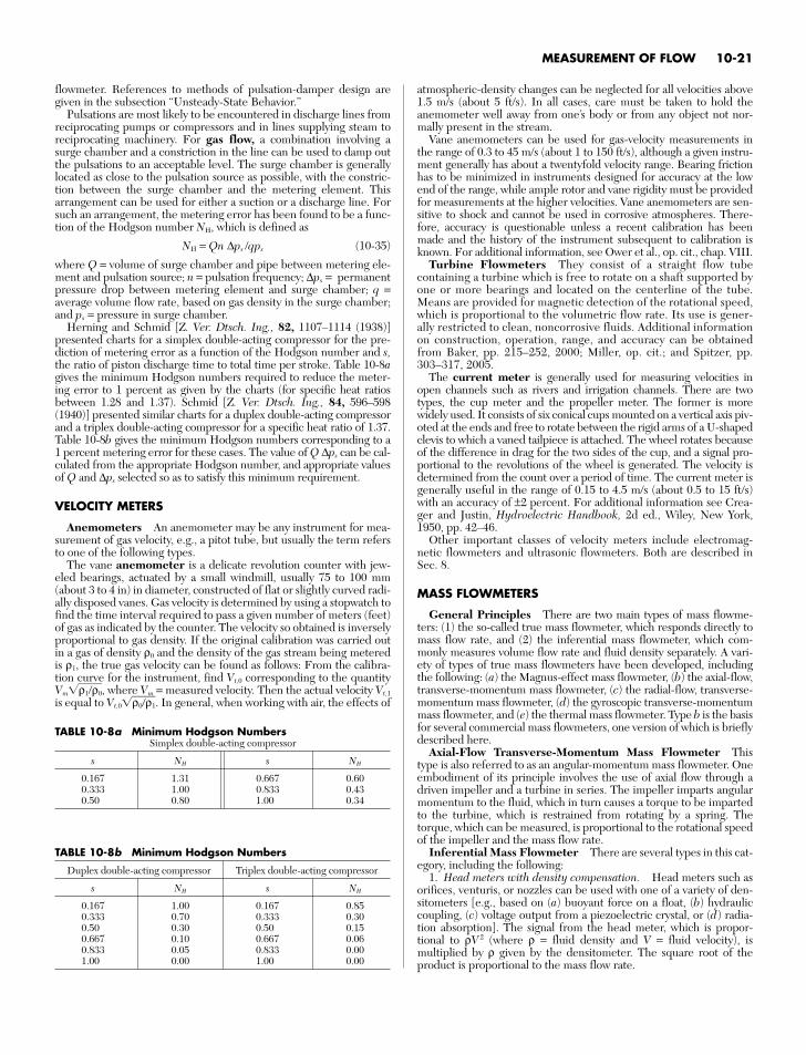
flowmeter. References to methods of pulsation-damper design aregiven in the subsection “Unsteady-State Behavior.”
Pulsations are most likely to be encountered in discharge lines fromreciprocating pumps or compressors and in lines supplying steam toreciprocating machinery. For gas flow, a combination involving asurge chamber and a constriction in the line can be used to damp outthe pulsations to an acceptable level. The surge chamber is generallylocated as close to the pulsation source as possible, with the constric-tion between the surge chamber and the metering element. Thisarrangement can be used for either a suction or a discharge line. Forsuch an arrangement, the metering error has been found to be a func-tion of the Hodgson number NH, which is defined as
NH = Qn ∆ps /qps (10-35)
where Q = volume of surge chamber and pipe between metering ele-ment and pulsation source; n = pulsation frequency; ∆ps = permanentpressure drop between metering element and surge chamber; q =average volume flow rate, based on gas density in the surge chamber;and ps = pressure in surge chamber.
Herning and Schmid [Z. Ver. Dtsch. Ing., 82, 1107–1114 (1938)]presented charts for a simplex double-acting compressor for the pre-diction of metering error as a function of the Hodgson number and s,the ratio of piston discharge time to total time per stroke. Table 10-8agives the minimum Hodgson numbers required to reduce the meter-ing error to 1 percent as given by the charts (for specific heat ratiosbetween 1.28 and 1.37). Schmid [Z. Ver. Dtsch. Ing., 84, 596–598(1940)] presented similar charts for a duplex double-acting compressorand a triplex double-acting compressor for a specific heat ratio of 1.37.Table 10-8b gives the minimum Hodgson numbers corresponding to a1 percent metering error for these cases. The value of Q ∆ps can be cal-culated from the appropriate Hodgson number, and appropriate valuesof Q and ∆ps selected so as to satisfy this minimum requirement.
VELOCITY METERS
Anemometers An anemometer may be any instrument for mea-surement of gas velocity, e.g., a pitot tube, but usually the term refersto one of the following types.
The vane anemometer is a delicate revolution counter with jew-eled bearings, actuated by a small windmill, usually 75 to 100 mm(about 3 to 4 in) in diameter, constructed of flat or slightly curved radi-ally disposed vanes. Gas velocity is determined by using a stopwatch tofind the time interval required to pass a given number of meters (feet)of gas as indicated by the counter. The velocity so obtained is inverselyproportional to gas density. If the original calibration was carried outin a gas of density ρ0 and the density of the gas stream being meteredis ρ1, the true gas velocity can be found as follows: From the calibra-tion curve for the instrument, find Vt,0 corresponding to the quantityVmρ1/ρ0, where Vm = measured velocity. Then the actual velocity Vt,1
is equal to Vt,0ρ0/ρ1. In general, when working with air, the effects of
atmospheric-density changes can be neglected for all velocities above1.5 m/s (about 5 ft/s). In all cases, care must be taken to hold theanemometer well away from one’s body or from any object not nor-mally present in the stream.
Vane anemometers can be used for gas-velocity measurements inthe range of 0.3 to 45 m/s (about 1 to 150 ft/s), although a given instru-ment generally has about a twentyfold velocity range. Bearing frictionhas to be minimized in instruments designed for accuracy at the lowend of the range, while ample rotor and vane rigidity must be providedfor measurements at the higher velocities. Vane anemometers are sen-sitive to shock and cannot be used in corrosive atmospheres. There-fore, accuracy is questionable unless a recent calibration has beenmade and the history of the instrument subsequent to calibration isknown. For additional information, see Ower et al., op. cit., chap. VIII.
Turbine Flowmeters They consist of a straight flow tubecontaining a turbine which is free to rotate on a shaft supported byone or more bearings and located on the centerline of the tube.Means are provided for magnetic detection of the rotational speed,which is proportional to the volumetric flow rate. Its use is gener-ally restricted to clean, noncorrosive fluids. Additional informationon construction, operation, range, and accuracy can be obtainedfrom Baker, pp. 215–252, 2000; Miller, op. cit.; and Spitzer, pp.303–317, 2005.
The current meter is generally used for measuring velocities inopen channels such as rivers and irrigation channels. There are twotypes, the cup meter and the propeller meter. The former is morewidely used. It consists of six conical cups mounted on a vertical axis piv-oted at the ends and free to rotate between the rigid arms of a U-shapedclevis to which a vaned tailpiece is attached. The wheel rotates becauseof the difference in drag for the two sides of the cup, and a signal pro-portional to the revolutions of the wheel is generated. The velocity isdetermined from the count over a period of time. The current meter isgenerally useful in the range of 0.15 to 4.5 m/s (about 0.5 to 15 ft/s)with an accuracy of ±2 percent. For additional information see Crea-ger and Justin, Hydroelectric Handbook, 2d ed., Wiley, New York,1950, pp. 42–46.
Other important classes of velocity meters include electromag-netic flowmeters and ultrasonic flowmeters. Both are described inSec. 8.
MASS FLOWMETERS
General Principles There are two main types of mass flowme-ters: (1) the so-called true mass flowmeter, which responds directly tomass flow rate, and (2) the inferential mass flowmeter, which com-monly measures volume flow rate and fluid density separately. A vari-ety of types of true mass flowmeters have been developed, includingthe following: (a) the Magnus-effect mass flowmeter, (b) the axial-flow,transverse-momentum mass flowmeter, (c) the radial-flow, transverse-momentum mass flowmeter, (d) the gyroscopic transverse-momentummass flowmeter, and (e) the thermal mass flowmeter. Type b is the basisfor several commercial mass flowmeters, one version of which is brieflydescribed here.
Axial-Flow Transverse-Momentum Mass Flowmeter Thistype is also referred to as an angular-momentum mass flowmeter. Oneembodiment of its principle involves the use of axial flow through adriven impeller and a turbine in series. The impeller imparts angularmomentum to the fluid, which in turn causes a torque to be impartedto the turbine, which is restrained from rotating by a spring. Thetorque, which can be measured, is proportional to the rotational speedof the impeller and the mass flow rate.
Inferential Mass Flowmeter There are several types in this cat-egory, including the following:
1. Head meters with density compensation. Head meters such asorifices, venturis, or nozzles can be used with one of a variety of den-sitometers [e.g., based on (a) buoyant force on a float, (b) hydrauliccoupling, (c) voltage output from a piezoelectric crystal, or (d) radia-tion absorption]. The signal from the head meter, which is propor-tional to ρV 2 (where ρ = fluid density and V = fluid velocity), ismultiplied by ρ given by the densitometer. The square root of theproduct is proportional to the mass flow rate.
MEASUREMENT OF FLOW 10-21
TABLE 10-8a Minimum Hodgson NumbersSimplex double-acting compressor
s NH s NH
0.167 1.31 0.667 0.600.333 1.00 0.833 0.430.50 0.80 1.00 0.34
TABLE 10-8b Minimum Hodgson Numbers
Duplex double-acting compressor Triplex double-acting compressor
s NH s NH
0.167 1.00 0.167 0.850.333 0.70 0.333 0.300.50 0.30 0.50 0.150.667 0.10 0.667 0.060.833 0.05 0.833 0.001.00 0.00 1.00 0.00
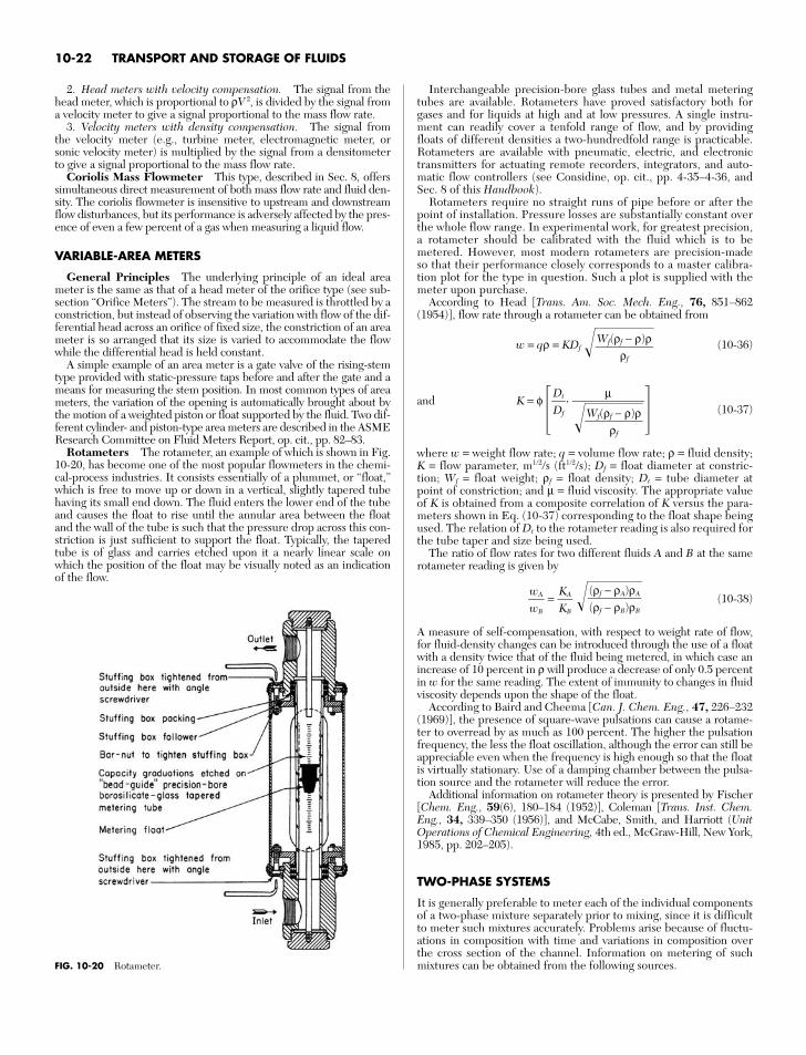
2. Head meters with velocity compensation. The signal from thehead meter, which is proportional to ρV 2, is divided by the signal froma velocity meter to give a signal proportional to the mass flow rate.
3. Velocity meters with density compensation. The signal fromthe velocity meter (e.g., turbine meter, electromagnetic meter, orsonic velocity meter) is multiplied by the signal from a densitometerto give a signal proportional to the mass flow rate.
Coriolis Mass Flowmeter This type, described in Sec. 8, offerssimultaneous direct measurement of both mass flow rate and fluid den-sity. The coriolis flowmeter is insensitive to upstream and downstreamflow disturbances, but its performance is adversely affected by the pres-ence of even a few percent of a gas when measuring a liquid flow.
VARIABLE-AREA METERS
General Principles The underlying principle of an ideal areameter is the same as that of a head meter of the orifice type (see sub-section “Orifice Meters”). The stream to be measured is throttled by aconstriction, but instead of observing the variation with flow of the dif-ferential head across an orifice of fixed size, the constriction of an areameter is so arranged that its size is varied to accommodate the flowwhile the differential head is held constant.
A simple example of an area meter is a gate valve of the rising-stemtype provided with static-pressure taps before and after the gate and ameans for measuring the stem position. In most common types of areameters, the variation of the opening is automatically brought about bythe motion of a weighted piston or float supported by the fluid. Two dif-ferent cylinder- and piston-type area meters are described in the ASMEResearch Committee on Fluid Meters Report, op. cit., pp. 82–83.
Rotameters The rotameter, an example of which is shown in Fig.10-20, has become one of the most popular flowmeters in the chemi-cal-process industries. It consists essentially of a plummet, or “float,”which is free to move up or down in a vertical, slightly tapered tubehaving its small end down. The fluid enters the lower end of the tubeand causes the float to rise until the annular area between the floatand the wall of the tube is such that the pressure drop across this con-striction is just sufficient to support the float. Typically, the taperedtube is of glass and carries etched upon it a nearly linear scale onwhich the position of the float may be visually noted as an indicationof the flow.
Interchangeable precision-bore glass tubes and metal meteringtubes are available. Rotameters have proved satisfactory both forgases and for liquids at high and at low pressures. A single instru-ment can readily cover a tenfold range of flow, and by providingfloats of different densities a two-hundredfold range is practicable.Rotameters are available with pneumatic, electric, and electronictransmitters for actuating remote recorders, integrators, and auto-matic flow controllers (see Considine, op. cit., pp. 4-35–4-36, andSec. 8 of this Handbook).
Rotameters require no straight runs of pipe before or after thepoint of installation. Pressure losses are substantially constant overthe whole flow range. In experimental work, for greatest precision,a rotameter should be calibrated with the fluid which is to bemetered. However, most modern rotameters are precision-madeso that their performance closely corresponds to a master calibra-tion plot for the type in question. Such a plot is supplied with themeter upon purchase.
According to Head [Trans. Am. Soc. Mech. Eng., 76, 851–862(1954)], flow rate through a rotameter can be obtained from
w = qρ = KDf (10-36)
and K = φ , (10-37)
where w = weight flow rate; q = volume flow rate; ρ = fluid density; K = flow parameter, m1/2/s (ft1/2/s); Df = float diameter at constric-tion; Wf = float weight; ρf = float density; Dt = tube diameter atpoint of constriction; and µ = fluid viscosity. The appropriate valueof K is obtained from a composite correlation of K versus the para-meters shown in Eq. (10-37) corresponding to the float shape beingused. The relation of Dt to the rotameter reading is also required forthe tube taper and size being used.
The ratio of flow rates for two different fluids A and B at the samerotameter reading is given by
= (10-38)
A measure of self-compensation, with respect to weight rate of flow,for fluid-density changes can be introduced through the use of a floatwith a density twice that of the fluid being metered, in which case anincrease of 10 percent in ρ will produce a decrease of only 0.5 percentin w for the same reading. The extent of immunity to changes in fluidviscosity depends upon the shape of the float.
According to Baird and Cheema [Can. J. Chem. Eng., 47, 226–232(1969)], the presence of square-wave pulsations can cause a rotame-ter to overread by as much as 100 percent. The higher the pulsationfrequency, the less the float oscillation, although the error can still beappreciable even when the frequency is high enough so that the floatis virtually stationary. Use of a damping chamber between the pulsa-tion source and the rotameter will reduce the error.
Additional information on rotameter theory is presented by Fischer[Chem. Eng., 59(6), 180–184 (1952)], Coleman [Trans. Inst. Chem.Eng., 34, 339–350 (1956)], and McCabe, Smith, and Harriott (UnitOperations of Chemical Engineering, 4th ed., McGraw-Hill, New York,1985, pp. 202–205).
TWO-PHASE SYSTEMS
It is generally preferable to meter each of the individual componentsof a two-phase mixture separately prior to mixing, since it is difficultto meter such mixtures accurately. Problems arise because of fluctu-ations in composition with time and variations in composition overthe cross section of the channel. Information on metering of suchmixtures can be obtained from the following sources.
(ρf − ρA)ρA(ρf − ρB)ρB
KAKB
wAwB
µ
Wf(ρρ
f −fρ)ρ
DtDf
Wf(ρf − ρ)ρ
ρf
10-22 TRANSPORT AND STORAGE OF FLUIDS
FIG. 10-20 Rotameter.
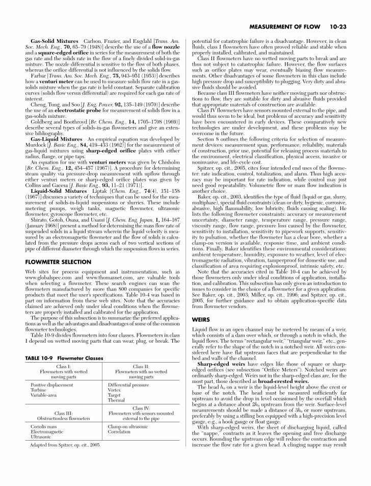
Gas-Solid Mixtures Carlson, Frazier, and Engdahl [Trans. Am.Soc. Mech. Eng., 70, 65–79 (1948)] describe the use of a flow nozzleand a square-edged orifice in series for the measurement of both thegas rate and the solids rate in the flow of a finely divided solid-in-gasmixture. The nozzle differential is sensitive to the flow of both phases,whereas the orifice differential is not influenced by the solids flow.
Farbar [Trans. Am. Soc. Mech. Eng., 75, 943–951 (1953)] describeshow a venturi meter can be used to measure solids flow rate in a gas-solids mixture when the gas rate is held constant. Separate calibrationcurves (solids flow versus differential) are required for each gas rate ofinterest.
Cheng, Tung, and Soo [J. Eng. Power, 92, 135–149 (1970)] describethe use of an electrostatic probe for measurement of solids flow in agas-solids mixture.
Goldberg and Boothroyd [Br. Chem. Eng., 14, 1705–1708 (1969)]describe several types of solids-in-gas flowmeters and give an exten-sive bibliography.
Gas-Liquid Mixtures An empirical equation was developed byMurdock [J. Basic Eng., 84, 419–433 (1962)] for the measurement ofgas-liquid mixtures using sharp-edged orifice plates with eitherradius, flange, or pipe taps.
An equation for use with venturi meters was given by Chisholm[Br. Chem. Eng., 12, 454–457 (1967)]. A procedure for determiningsteam quality via pressure-drop measurement with upflow througheither venturi meters or sharp-edged orifice plates was given byCollins and Gacesa [J. Basic Eng., 93, 11–21 (1971)].
Liquid-Solid Mixtures Liptak [Chem. Eng., 74(4), 151–158(1967)] discusses a variety of techniques that can be used for the mea-surement of solids-in-liquid suspensions or slurries. These includemetering pumps, weigh tanks, magnetic flowmeter, ultrasonicflowmeter, gyroscope flowmeter, etc.
Shirato, Gotoh, Osasa, and Usami [J. Chem. Eng. Japan, 1, 164–167(January 1968)] present a method for determining the mass flow rate ofsuspended solids in a liquid stream wherein the liquid velocity is mea-sured by an electromagnetic flowmeter and the flow of solids is calcu-lated from the pressure drops across each of two vertical sections ofpipe of different diameter through which the suspension flows in series.
FLOWMETER SELECTION
Web sites for process equipment and instrumentation, such aswww.globalspec.com and www.thomasnet.com, are valuable toolswhen selecting a flowmeter. These search engines can scan theflowmeters manufactured by more than 800 companies for specificproducts that meet the user’s specifications. Table 10-4 was based inpart on information from these web sites. Note that the accuraciesclaimed are achieved only under ideal conditions when the flowme-ters are properly installed and calibrated for the application.
The purpose of this subsection is to summarize the preferred applica-tions as well as the advantages and disadvantages of some of the commonflowmeter technologies.
Table 10-9 divides flowmeters into four classes. Flowmeters in classI depend on wetted moving parts that can wear, plug, or break. The
potential for catastrophic failure is a disadvantage. However, in cleanfluids, class I flowmeters have often proved reliable and stable whenproperly installed, calibrated, and maintained.
Class II flowmeters have no wetted moving parts to break and arethus not subject to catastrophic failure. However, the flow surfacessuch as orifice plates may wear, eventually biasing flow measure-ments. Other disadvantages of some flowmeters in this class includehigh pressure drop and susceptibility to plugging. Very dirty and abra-sive fluids should be avoided.
Because class III flowmeters have neither moving parts nor obstruc-tions to flow, they are suitable for dirty and abrasive fluids providedthat appropriate materials of construction are available.
Class IV flowmeters have sensors mounted external to the pipe, andwould thus seem to be ideal, but problems of accuracy and sensitivityhave been encountered in early devices. These comparatively newtechnologies are under development, and these problems may beovercome in the future.
Section 8 outlines the following criteria for selection of measure-ment devices: measurement span, performance, reliability, materialsof construction, prior use, potential for releasing process materials tothe environment, electrical classification, physical access, invasive ornoninvasive, and life-cycle cost.
Spitzer, op. cit., 2005, cites four intended end uses of the flowme-ter: rate indication, control, totalization, and alarm. Thus high accu-racy may be important for rate indication, while control may justneed good repeatability. Volumetric flow or mass flow indication isanother choice.
Baker, op. cit., 2003, identifies the type of fluid (liquid or gas, slurry,multiphase), special fluid constraints (clean or dirty, hygienic, corrosive,abrasive, high flammability, low lubricity, fluids causing scaling). Helists the following flowmeter constraints: accuracy or measurementuncertainty, diameter range, temperature range, pressure range,viscosity range, flow range, pressure loss caused by the flowmeter,sensitivity to installation, sensitivity to pipework supports, sensitiv-ity to pulsation, whether the flowmeter has a clear bore, whether aclamp-on version is available, response time, and ambient condi-tions. Finally, Baker identifies these environmental considerations:ambient temperature, humidity, exposure to weather, level of elec-tromagnetic radiation, vibration, tamperproof for domestic use, andclassification of area requiring explosionproof, intrinsic safety, etc.
Note that the accuracies cited in Table 10-4 can be achieved bythose flowmeters only under ideal conditions of application, installa-tion, and calibration. This subsection has only given an introduction toissues to consider in the choice of a flowmeter for a given application.See Baker, op. cit., 2003; Miller, op. cit., 1996; and Spitzer, op. cit.,2005, for further guidance and to obtain application-specific datafrom flowmeter vendors.
WEIRS
Liquid flow in an open channel may be metered by means of a weir,which consists of a dam over which, or through a notch in which, theliquid flows. The terms “rectangular weir,” “triangular weir,” etc., gen-erally refer to the shape of the notch in a notched weir. All weirs con-sidered here have flat upstream faces that are perpendicular to thebed and walls of the channel.
Sharp-edged weirs have edges like those of square or sharp-edged orifices (see subsection “Orifice Meters”). Notched weirs areordinarily sharp-edged. Weirs not in the sharp-edged class are, for themost part, those described as broad-crested weirs.
The head h0 on a weir is the liquid-level height above the crest orbase of the notch. The head must be measured sufficiently farupstream to avoid the drop in level occasioned by the overfall whichbegins at a distance about 2h0 upstream from the weir. Surface-levelmeasurements should be made a distance of 3h0 or more upstream,preferably by using a stilling box equipped with a high-precision levelgauge, e.g., a hook gauge or float gauge.
With sharp-edged weirs, the sheet of discharging liquid, calledthe “nappe,” contracts as it leaves the opening and free dischargeoccurs. Rounding the upstream edge will reduce the contraction andincrease the flow rate for a given head. A clinging nappe may result
MEASUREMENT OF FLOW 10-23
TABLE 10-9 Flowmeter Classes
Class I: Class II:Flowmeters with wetted Flowmeters with no wetted
moving parts moving parts
Positive displacement Differential pressureTurbine VortexVariable-area Target
Thermal
Class IV:Class III: Flowmeters with sensors mounted
Obstructionless flowmeters external to the pipe
Coriolis mass Clamp-on ultrasonicElectromagnetic CorrelationUltrasonic
Adapted from Spitzer, op. cit., 2005.
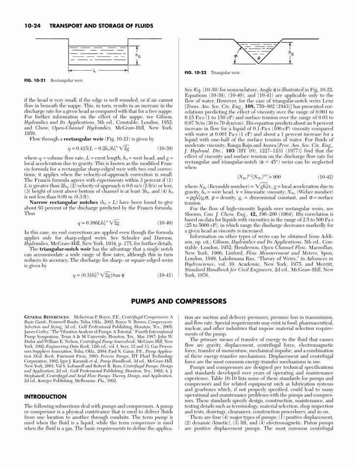
if the head is very small, if the edge is well rounded, or if air cannotflow in beneath the nappe. This, in turn, results in an increase in thedischarge rate for a given head as compared with that for a free nappe.For further information on the effect of the nappe, see Gibson,Hydraulics and Its Applications, 5th ed., Constable, London, 1952;and Chow, Open-Channel Hydraulics, McGraw-Hill, New York,1959.
Flow through a rectangular weir (Fig. 10-21) is given by
q = 0.415(L − 0.2h0)h01.5 2g (10-39)
where q = volume flow rate, L = crest length, h0 = weir head, and g =local acceleration due to gravity. This is known as the modified Fran-cis formula for a rectangular sharp-edged weir with two end correc-tions; it applies when the velocity-of-approach correction is small.The Francis formula agrees with experiments within 3 percent if (1)L is greater than 2h0, (2) velocity of approach is 0.6 m/s (2 ft/s) or less,(3) height of crest above bottom of channel is at least 3h0, and (4) h0
is not less than 0.09 m (0.3 ft).Narrow rectangular notches (h0 > L) have been found to give
about 93 percent of the discharge predicted by the Francis formula.Thus
q = 0.386Lh01.5 2g (10-40)
In this case, no end corrections are applied even though the formulaapplies only for sharp-edged weirs. See Schoder and Dawson,Hydraulics, McGraw-Hill, New York, 1934, p. 175, for further details.
The triangular-notch weir has the advantage that a single notchcan accommodate a wide range of flow rates, although this in turnreduces its accuracy. The discharge for sharp- or square-edged weirsis given by
q = (0.31h02.5 2g)/tan φ (10-41)
See Eq. (10-39) for nomenclature. Angle φ is illustrated in Fig. 10-22.Equations (10-39), (10-40), and (10-41) are applicable only to theflow of water. However, for the case of triangular-notch weirs Lenz[Trans. Am. Soc. Civ. Eng., 108, 759–802 (1943)] has presented cor-relations predicting the effect of viscosity over the range of 0.001 to0.15 Pa⋅s (1 to 150 cP) and surface tension over the range of 0.03 to0.07 N/m (30 to 70 dyn/cm). His equation predicts about an 8 percentincrease in flow for a liquid of 0.1-Pa⋅s (100-cP) viscosity comparedwith water at 0.001 Pa⋅s (1 cP) and about a 1 percent increase for aliquid with one-half of the surface tension of water. For fluids ofmoderate viscosity, Ranga Raju and Asawa [Proc. Am. Soc. Civ. Eng.,J. Hydraul. Div., 103 (HY 10), 1227–1231 (1977)] find that theeffect of viscosity and surface tension on the discharge flow rate forrectangular and triangular-notch (φ 45°) weirs can be neglectedwhen
(NRe)0.2(NWe)0.6 > 900 (10-42)
where NRe (Reynolds number) = gh30v, g = local acceleration due to
gravity, h0 = weir head, ν = kinematic viscosity; NWe (Weber number)= ρgh2
0gcσ, ρ = density, gc = dimensional constant, and σ = surfacetension.
For the flow of high-viscosity liquids over rectangular weirs, seeSlocum, Can. J. Chem. Eng., 42, 196–200 (1964). His correlation isbased on data for liquids with viscosities in the range of 2.5 to 500 Pa⋅s(25 to 5000 cP), in which range the discharge decreases markedly fora given head as viscosity is increased.
Information on other types of weirs can be obtained from Addi-son, op. cit.; Gibson, Hydraulics and Its Applications, 5th ed., Con-stable, London, 1952; Henderson, Open Channel Flow, Macmillan,New York, 1966; Linford, Flow Measurement and Meters, Spon,London, 1949; Lakshmana Rao, “Theory of Weirs,” in Advances inHydroscience, vol. 10, Academic, New York, 1975; and Merritt,Standard Handbook for Civil Engineers, 2d ed., McGraw-Hill, NewYork, 1976.
10-24 TRANSPORT AND STORAGE OF FLUIDS
FIG. 10-21 Rectangular weir.
FIG. 10-22 Triangular weir.
PUMPS AND COMPRESSORS
GENERAL REFERENCES: Meherwan P. Boyce, P.E., Centrifugal Compressors: ABasic Guide, Pennwell Books, Tulsa, Okla., 2002; Royce N. Brown, Compressors:Selection and Sizing, 3d ed., Gulf Professional Publishing, Houston, Tex., 2005;James Corley, “The Vibration Analysis of Pumps: A Tutorial,” Fourth InternationalPump Symposium, Texas A & M University, Houston, Tex., May 1987; John W.Dufor and William E. Nelson, Centrifugal Pump Sourcebook, McGraw-Hill, NewYork, 1992; Engineering Data Book, 12th ed., vol. I, Secs. 12 and 13, Gas Proces-sors Suppliers Association, Tulsa, Okla., 2004; Paul N. Garay, P.E., Pump Applica-tion Desk Book, Fairmont Press, 1993; Process Pumps, IIT Fluid TechnologyCorporation, 1992; Igor J. Karassik et al., Pump Handbook, 3d ed., McGraw-Hill,New York, 2001; Val S. Lobanoff and Robert R. Ross, Centrifugal Pumps: Designand Application, 2d ed., Gulf Professional Publishing, Houston, Tex., 1992; A. J.Stephanoff, Centrifugal and Axial Flow Pumps: Theory, Design, and Application,2d ed., Krieger Publishing, Melbourne, Fla., 1992.
INTRODUCTION
The following subsections deal with pumps and compressors. A pumpor compressor is a physical contrivance that is used to deliver fluidsfrom one location to another through conduits. The term pump isused when the fluid is a liquid, while the term compressor is usedwhen the fluid is a gas. The basic requirements to define the applica-
tion are suction and delivery pressures, pressure loss in transmission,and flow rate. Special requirements may exist in food, pharmaceutical,nuclear, and other industries that impose material selection require-ments of the pump.
The primary means of transfer of energy to the fluid that causesflow are gravity, displacement, centrifugal force, electromagneticforce, transfer of momentum, mechanical impulse, and a combinationof these energy-transfer mechanisms. Displacement and centrifugalforce are the most common energy-transfer mechanisms in use.
Pumps and compressors are designed per technical specificationsand standards developed over years of operating and maintenanceexperience. Table 10-10 lists some of these standards for pumps andcompressors and for related equipment such as lubrication systemsand gearboxes which, if not properly specified, could lead to manyoperational and maintenance problems with the pumps and compres-sors. These standards specify design, construction, maintenance, andtesting details such as terminology, material selection, shop inspectionand tests, drawings, clearances, construction procedures, and so on.
There are four (4) major types of pumps: (1) positive displacement,(2) dynamic (kinetic), (3) lift, and (4) electromagnetic. Piston pumpsare positive displacement pumps. The most common centrifugal
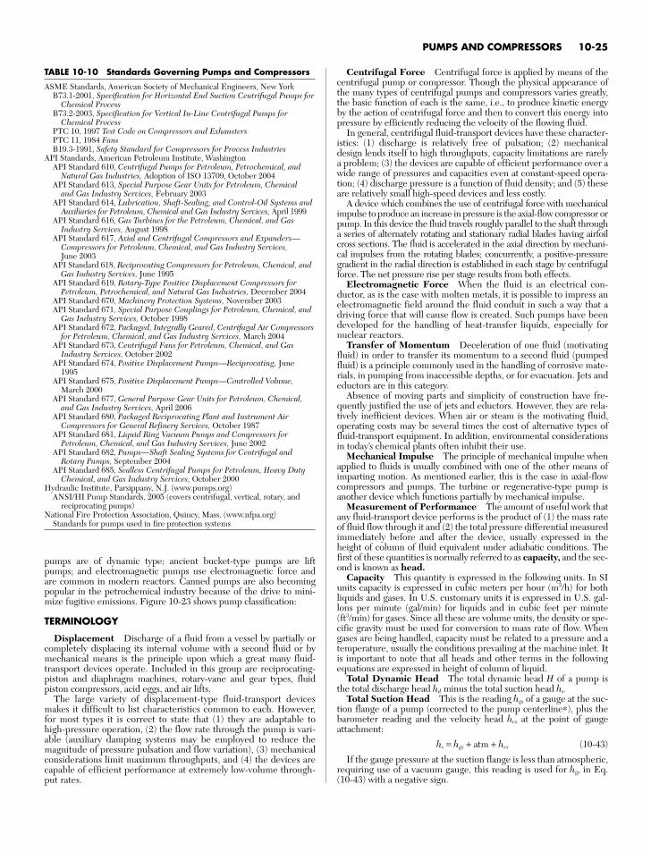
pumps are of dynamic type; ancient bucket-type pumps are liftpumps; and electromagnetic pumps use electromagnetic force andare common in modern reactors. Canned pumps are also becomingpopular in the petrochemical industry because of the drive to mini-mize fugitive emissions. Figure 10-23 shows pump classification:
TERMINOLOGY
Displacement Discharge of a fluid from a vessel by partially orcompletely displacing its internal volume with a second fluid or bymechanical means is the principle upon which a great many fluid-transport devices operate. Included in this group are reciprocating-piston and diaphragm machines, rotary-vane and gear types, fluidpiston compressors, acid eggs, and air lifts.
The large variety of displacement-type fluid-transport devicesmakes it difficult to list characteristics common to each. However,for most types it is correct to state that (1) they are adaptable tohigh-pressure operation, (2) the flow rate through the pump is vari-able (auxiliary damping systems may be employed to reduce themagnitude of pressure pulsation and flow variation), (3) mechanicalconsiderations limit maximum throughputs, and (4) the devices arecapable of efficient performance at extremely low-volume through-put rates.
Centrifugal Force Centrifugal force is applied by means of thecentrifugal pump or compressor. Though the physical appearance ofthe many types of centrifugal pumps and compressors varies greatly,the basic function of each is the same, i.e., to produce kinetic energyby the action of centrifugal force and then to convert this energy intopressure by efficiently reducing the velocity of the flowing fluid.
In general, centrifugal fluid-transport devices have these character-istics: (1) discharge is relatively free of pulsation; (2) mechanicaldesign lends itself to high throughputs, capacity limitations are rarelya problem; (3) the devices are capable of efficient performance over awide range of pressures and capacities even at constant-speed opera-tion; (4) discharge pressure is a function of fluid density; and (5) theseare relatively small high-speed devices and less costly.
A device which combines the use of centrifugal force with mechanicalimpulse to produce an increase in pressure is the axial-flow compressor orpump. In this device the fluid travels roughly parallel to the shaft througha series of alternately rotating and stationary radial blades having airfoilcross sections. The fluid is accelerated in the axial direction by mechani-cal impulses from the rotating blades; concurrently, a positive-pressuregradient in the radial direction is established in each stage by centrifugalforce. The net pressure rise per stage results from both effects.
Electromagnetic Force When the fluid is an electrical con-ductor, as is the case with molten metals, it is possible to impress anelectromagnetic field around the fluid conduit in such a way that adriving force that will cause flow is created. Such pumps have beendeveloped for the handling of heat-transfer liquids, especially fornuclear reactors.
Transfer of Momentum Deceleration of one fluid (motivatingfluid) in order to transfer its momentum to a second fluid (pumpedfluid) is a principle commonly used in the handling of corrosive mate-rials, in pumping from inaccessible depths, or for evacuation. Jets andeductors are in this category.
Absence of moving parts and simplicity of construction have fre-quently justified the use of jets and eductors. However, they are rela-tively inefficient devices. When air or steam is the motivating fluid,operating costs may be several times the cost of alternative types offluid-transport equipment. In addition, environmental considerationsin today’s chemical plants often inhibit their use.
Mechanical Impulse The principle of mechanical impulse whenapplied to fluids is usually combined with one of the other means ofimparting motion. As mentioned earlier, this is the case in axial-flowcompressors and pumps. The turbine or regenerative-type pump isanother device which functions partially by mechanical impulse.
Measurement of Performance The amount of useful work thatany fluid-transport device performs is the product of (1) the mass rateof fluid flow through it and (2) the total pressure differential measuredimmediately before and after the device, usually expressed in theheight of column of fluid equivalent under adiabatic conditions. Thefirst of these quantities is normally referred to as capacity, and the sec-ond is known as head.
Capacity This quantity is expressed in the following units. In SIunits capacity is expressed in cubic meters per hour (m3/h) for bothliquids and gases. In U.S. customary units it is expressed in U.S. gal-lons per minute (gal/min) for liquids and in cubic feet per minute(ft3/min) for gases. Since all these are volume units, the density or spe-cific gravity must be used for conversion to mass rate of flow. Whengases are being handled, capacity must be related to a pressure and atemperature, usually the conditions prevailing at the machine inlet. Itis important to note that all heads and other terms in the followingequations are expressed in height of column of liquid.
Total Dynamic Head The total dynamic head H of a pump isthe total discharge head hd minus the total suction head hs.
Total Suction Head This is the reading hgs of a gauge at the suc-tion flange of a pump (corrected to the pump centerline∗), plus thebarometer reading and the velocity head hvs at the point of gaugeattachment:
hs = hgs + atm + hvs (10-43)
If the gauge pressure at the suction flange is less than atmospheric,requiring use of a vacuum gauge, this reading is used for hgs in Eq.(10-43) with a negative sign.
PUMPS AND COMPRESSORS 10-25
TABLE 10-10 Standards Governing Pumps and Compressors
ASME Standards, American Society of Mechanical Engineers, New YorkB73.1-2001, Specification for Horizontal End Suction Centrifugal Pumps for
Chemical ProcessB73.2-2003, Specification for Vertical In-Line Centrifugal Pumps for
Chemical ProcessPTC 10, 1997 Test Code on Compressors and ExhaustersPTC 11, 1984 FansB19.3-1991, Safety Standard for Compressors for Process Industries
API Standards, American Petroleum Institute, WashingtonAPI Standard 610, Centrifugal Pumps for Petroleum, Petrochemical, and
Natural Gas Industries, Adoption of ISO 13709, October 2004API Standard 613, Special Purpose Gear Units for Petroleum, Chemical
and Gas Industry Services, February 2003API Standard 614, Lubrication, Shaft-Sealing, and Control-Oil Systems and
Auxiliaries for Petroleum, Chemical and Gas Industry Services, April 1999API Standard 616, Gas Turbines for the Petroleum, Chemical, and Gas
Industry Services, August 1998API Standard 617, Axial and Centrifugal Compressors and Expanders—
Compressors for Petroleum, Chemical, and Gas Industry Services,June 2003
API Standard 618, Reciprocating Compressors for Petroleum, Chemical, andGas Industry Services, June 1995
API Standard 619, Rotary-Type Positive Displacement Compressors forPetroleum, Petrochemical, and Natural Gas Industries, December 2004
API Standard 670, Machinery Protection Systems, November 2003API Standard 671, Special Purpose Couplings for Petroleum, Chemical, and
Gas Industry Services, October 1998API Standard 672, Packaged, Integrally Geared, Centrifugal Air Compressors
for Petroleum, Chemical, and Gas Industry Services, March 2004API Standard 673, Centrifugal Fans for Petroleum, Chemical, and Gas
Industry Services, October 2002API Standard 674, Positive Displacement Pumps—Reciprocating, June
1995API Standard 675, Positive Displacement Pumps—Controlled Volume,
March 2000API Standard 677, General Purpose Gear Units for Petroleum, Chemical,
and Gas Industry Services, April 2006API Standard 680, Packaged Reciprocating Plant and Instrument Air
Compressors for General Refinery Services, October 1987API Standard 681, Liquid Ring Vacuum Pumps and Compressors for
Petroleum, Chemical, and Gas Industry Services, June 2002API Standard 682, Pumps—Shaft Sealing Systems for Centrifugal and
Rotary Pumps, September 2004API Standard 685, Sealless Centrifugal Pumps for Petroleum, Heavy Duty
Chemical, and Gas Industry Services, October 2000Hydraulic Institute, Parsippany, N.J. (www.pumps.org)
ANSI/HI Pump Standards, 2005 (covers centrifugal, vertical, rotary, andreciprocating pumps)
National Fire Protection Association, Quincy, Mass. (www.nfpa.org) Standards for pumps used in fire protection systems
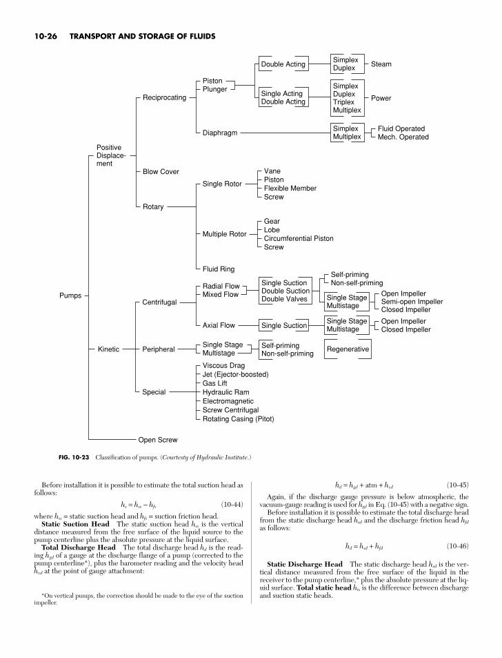
Before installation it is possible to estimate the total suction head asfollows:
hs = hss − hfs (10-44)
where hss = static suction head and hfs = suction friction head.Static Suction Head The static suction head hss is the vertical
distance measured from the free surface of the liquid source to thepump centerline plus the absolute pressure at the liquid surface.
Total Discharge Head The total discharge head hd is the read-ing hgd of a gauge at the discharge flange of a pump (corrected to thepump centerline*), plus the barometer reading and the velocity headhvd at the point of gauge attachment:
hd = hgd + atm + hvd (10-45)
Again, if the discharge gauge pressure is below atmospheric, thevacuum-gauge reading is used for hgd in Eq. (10-45) with a negative sign.
Before installation it is possible to estimate the total discharge headfrom the static discharge head hsd and the discharge friction head hfd
as follows:
hd = hsd + hfd (10-46)
Static Discharge Head The static discharge head hsd is the ver-tical distance measured from the free surface of the liquid in thereceiver to the pump centerline,* plus the absolute pressure at the liq-uid surface. Total static head hts is the difference between dischargeand suction static heads.
10-26 TRANSPORT AND STORAGE OF FLUIDS
Pumps
PositiveDisplace-ment
Reciprocating
Blow Cover
Rotary
Single Rotor
Multiple Rotor
Fluid Ring
Viscous DragJet (Ejector-boosted)Gas LiftHydraulic RamElectromagneticScrew CentrifugalRotating Casing (Pitot)
Open Screw
VanePistonFlexible MemberScrew
Double Acting
Single ActingDouble Acting
PistonPlunger
DiaphragmFluid OperatedMech. Operated
GearLobeCircumferential PistonScrew
SimplexDuplex Steam
Power
SimplexDuplexTriplexMultiplex
SimplexMultiplex
Kinetic
Centrifugal
Peripheral
Special
Single SuctionDouble SuctionDouble Valves
Single Suction
Radial FlowMixed Flow
Axial FlowOpen ImpellerClosed Impeller
Open ImpellerSemi-open ImpellerClosed Impeller
Self-primingNon-self-priming
Single StageMultistage
Single StageMultistage
Single StageMultistage
Self-primingNon-self-priming
Regenerative
FIG. 10-23 Classification of pumps. (Courtesty of Hydraulic Institute.)
*On vertical pumps, the correction should be made to the eye of the suctionimpeller.
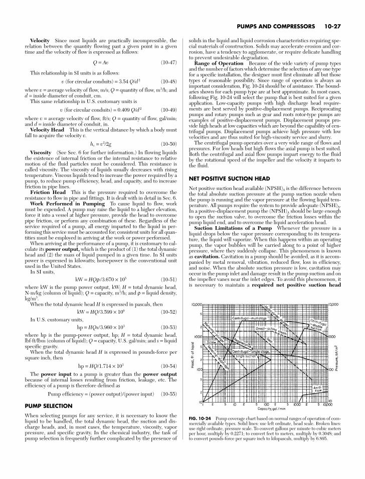
Velocity Since most liquids are practically incompressible, therelation between the quantity flowing past a given point in a giventime and the velocity of flow is expressed as follows:
Q = Av (10-47)
This relationship in SI units is as follows:
v (for circular conduits) = 3.54 Q/d 2 (10-48)
where v = average velocity of flow, m/s; Q = quantity of flow, m3/h; andd = inside diameter of conduit, cm.
This same relationship in U.S. customary units is
v (for circular conduits) = 0.409 Q/d 2 (10-49)
where v = average velocity of flow, ft/s; Q = quantity of flow, gal/min;and d = inside diameter of conduit, in.
Velocity Head This is the vertical distance by which a body mustfall to acquire the velocity v.
hv = v2/2g (10-50)
Viscosity (See Sec. 6 for further information.) In flowing liquidsthe existence of internal friction or the internal resistance to relativemotion of the fluid particles must be considered. This resistance iscalled viscosity. The viscosity of liquids usually decreases with risingtemperature. Viscous liquids tend to increase the power required by apump, to reduce pump efficiency, head, and capacity, and to increasefriction in pipe lines.
Friction Head This is the pressure required to overcome theresistance to flow in pipe and fittings. It is dealt with in detail in Sec. 6.
Work Performed in Pumping To cause liquid to flow, workmust be expended. A pump may raise the liquid to a higher elevation,force it into a vessel at higher pressure, provide the head to overcomepipe friction, or perform any combination of these. Regardless of theservice required of a pump, all energy imparted to the liquid in per-forming this service must be accounted for; consistent units for all quan-tities must be employed in arriving at the work or power performed.
When arriving at the performance of a pump, it is customary to cal-culate its power output, which is the product of (1) the total dynamichead and (2) the mass of liquid pumped in a given time. In SI unitspower is expressed in kilowatts; horsepower is the conventional unitused in the United States.
In SI units,kW = HQρ /3.670 × 105 (10-51)
where kW is the pump power output, kW; H = total dynamic head,N⋅m/kg (column of liquid); Q = capacity, m3/h; and ρ = liquid density,kg/m3.
When the total dynamic head H is expressed in pascals, thenkW = HQ/3.599 × 106 (10-52)
In U.S. customary units,hp = HQs/3.960 × 103 (10-53)
where hp is the pump-power output, hp; H = total dynamic head,lbf⋅ft/lbm (column of liquid); Q = capacity, U.S. gal/min; and s = liquidspecific gravity.
When the total dynamic head H is expressed in pounds-force persquare inch, then
hp = HQ/1.714 × 103 (10-54)The power input to a pump is greater than the power output
because of internal losses resulting from friction, leakage, etc. Theefficiency of a pump is therefore defined as
Pump efficiency = (power output)/(power input) (10-55)
PUMP SELECTION
When selecting pumps for any service, it is necessary to know theliquid to be handled, the total dynamic head, the suction and dis-charge heads, and, in most cases, the temperature, viscosity, vaporpressure, and specific gravity. In the chemical industry, the task ofpump selection is frequently further complicated by the presence of
solids in the liquid and liquid corrosion characteristics requiring spe-cial materials of construction. Solids may accelerate erosion and cor-rosion, have a tendency to agglomerate, or require delicate handlingto prevent undesirable degradation.
Range of Operation Because of the wide variety of pump typesand the number of factors which determine the selection of any one typefor a specific installation, the designer must first eliminate all but thosetypes of reasonable possibility. Since range of operation is always animportant consideration, Fig. 10-24 should be of assistance. The bound-aries shown for each pump type are at best approximate. In most cases,following Fig. 10-24 will select the pump that is best suited for a givenapplication. Low-capacity pumps with high discharge head require-ments are best served by positive-displacement pumps. Reciprocatingpumps and rotary pumps such as gear and roots rotor-type pumps areexamples of positive-displacement pumps. Displacement pumps pro-vide high heads at low capacities which are beyond the capability of cen-trifugal pumps. Displacement pumps achieve high pressure with lowvelocities and are thus suited for high-viscosity service and slurry.
The centrifugal pump operates over a very wide range of flows andpressures. For low heads but high flows the axial pump is best suited.Both the centrifugal and axial flow pumps impart energy to the fluidby the rotational speed of the impeller and the velocity it imparts tothe fluid.
NET POSITIVE SUCTION HEAD
Net positive suction head available (NPSH)A is the difference betweenthe total absolute suction pressure at the pump suction nozzle whenthe pump is running and the vapor pressure at the flowing liquid tem-perature. All pumps require the system to provide adequate (NPSH)A.In a positive-displacement pump the (NPSH)A should be large enoughto open the suction valve, to overcome the friction losses within thepump liquid end, and to overcome the liquid acceleration head.
Suction Limitations of a Pump Whenever the pressure in aliquid drops below the vapor pressure corresponding to its tempera-ture, the liquid will vaporize. When this happens within an operatingpump, the vapor bubbles will be carried along to a point of higherpressure, where they suddenly collapse. This phenomenon is knownas cavitation. Cavitation in a pump should be avoided, as it is accom-panied by metal removal, vibration, reduced flow, loss in efficiency,and noise. When the absolute suction pressure is low, cavitation mayoccur in the pump inlet and damage result in the pump suction and onthe impeller vanes near the inlet edges. To avoid this phenomenon, itis necessary to maintain a required net positive suction head
PUMPS AND COMPRESSORS 10-27
FIG. 10-24 Pump coverage chart based on normal ranges of operation of com-mercially available types. Solid lines: use left ordinate, head scale. Broken lines:use right ordinate, pressure scale. To convert gallons per minute to cubic metersper hour, multiply by 0.2271; to convert feet to meters, multiply by 0.3048; andto convert pounds-force per square inch to kilopascals, multiply by 6.895.
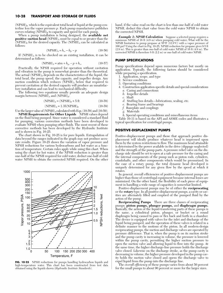
(NPSH)R, which is the equivalent total head of liquid at the pump cen-terline less the vapor pressure p. Each pump manufacturer publishescurves relating (NPSH)R to capacity and speed for each pump.
When a pump installation is being designed, the available netpositive suction head (NPSH)A must be equal to or greater than the(NPSH)R for the desired capacity. The (NPSH)A can be calculated asfollows:
(NPSH)A = hss − hfs − p (10-56)If (NPSH)A is to be checked on an existing installation, it can be
determined as follows:(NPSH)A = atm + hgs − p + hvs (10-57)
Practically, the NPSH required for operation without cavitationand vibration in the pump is somewhat greater than the theoretical.The actual (NPSH)R depends on the characteristics of the liquid, thetotal head, the pump speed, the capacity, and impeller design. Anysuction condition which reduces (NPSH)A below that required toprevent cavitation at the desired capacity will produce an unsatisfac-tory installation and can lead to mechanical difficulty.
The following two equations usually provide an adequate designmargin between (NPSH)A and (NPSH)R:
(NPSH)A = (NPSH)R + 5 ft (10-58)
(NPSH)A = 1.35(NPSH)R (10-59)Use the larger value of (NPSH)A calculated with Eqs. (10-58) and (10-59).
NPSH Requirements for Other Liquids NPSH values dependon the fluid being pumped. Since water is considered a standard fluidfor pumping, various correction methods have been developed toevaluate NPSH when pumping other fluids. The most recent of thesecorrective methods has been developed by the Hydraulic Instituteand is shown in Fig. 10-25.
The chart shown in Fig. 10-25 is for pure liquids. Extrapolation ofdata beyond the ranges indicated in the graph may not produce accu-rate results. Figure 10-25 shows the variation of vapor pressure andNPSH reductions for various hydrocarbons and hot water as a func-tion of temperature. Certain rules apply while using this chart. Whenusing the chart for hot water, if the NPSH reduction is greater thanone-half of the NPSH required for cold water, deduct one-half of coldwater NPSH to obtain the corrected NPSH required. On the other
hand, if the value read on the chart is less than one-half of cold waterNPSH, deduct this chart value from the cold water NPSH to obtainthe corrected NPSH.
Example 1: NPSH Calculation Suppose a selected pump requires aminimum NPSH of 16 ft (4.9 m) when pumping cold water; What will be theNPSH limitation to pump propane at 55°F (12.8°C) with a vapor pressure of100 psi? Using the chart in Fig. 10-25, NPSH reduction for propane gives 9.5 ft(2.9 m). This is greater than one-half of cold water NPSH of 16 ft (4.9 m). Thecorrected NPSH is therefore 8 ft (2.2 m) or one-half of cold water NPSH.
PUMP SPECIFICATIONS
Pump specifications depend upon numerous factors but mostly onapplication. Typically, the following factors should be consideredwhile preparing a specification.
1. Application, scope, and type2. Service conditions3. Operating conditions4. Construction application-specific details and special considerations
a. Casing and connectionsb. Impeller detailsc. Shaftd. Stuffing box details—lubrications, sealing, etc.e. Bearing frame and bearingsf. Baseplate and couplingsg. Materialsh. Special operating conditions and miscellaneous items
Table 10-11 is based on the API and ASME codes and illustrates atypical specification for centrifugal pumps.
POSITIVE-DISPLACEMENT PUMPS
Positive-displacement pumps and those that approach positive dis-placement will ideally produce whatever head is impressed uponthem by the system restrictions to flow. The maximum head attainableis determined by the power available in the drive (slippage neglected)and the strength of the pump parts. A pressure relief valve on the dis-charge side should be set to open at a safe pressure for the casing andthe internal components of the pump such as piston rods, cylinders,crankshafts, and other components which would be pressurized. Inthe case of a rotary pump, the total dynamic head developed isuniquely determined for any given flow by the speed at which itrotates.
In general, overall efficiencies of positive-displacement pumps arehigher than those of centrifugal equipment because internal losses areminimized. On the other hand, the flexibility of each piece of equip-ment in handling a wide range of capacities is somewhat limited.
Positive-displacement pumps may be of either the reciprocatingor the rotary type. In all positive-displacement pumps, a cavity or cav-ities are alternately filled and emptied of the pumped fluid by theaction of the pump.
Reciprocating Pumps There are three classes of reciprocatingpumps: piston pumps, plunger pumps, and diaphragm pumps.Basically, the action of the liquid-transferring parts of these pumps isthe same, a cylindrical piston, plunger, or bucket or a rounddiaphragm being caused to pass or flex back and forth in a chamber.The device is equipped with valves for the inlet and discharge of theliquid being pumped, and the operation of these valves is related in adefinite manner to the motions of the piston. In all modern-designreciprocating pumps, the suction and discharge valves are operated bypressure difference. That is, when the pump is on its suction strokeand the pump cavity is increasing in volume, the pressure is loweredwithin the pump cavity, permitting the higher suction pressure toopen the suction valve and allowing liquid to flow into the pump. Atthe same time, the higher discharge-line pressure holds the dischargevalve closed. Likewise on the discharge stroke, as the pump cavity isdecreasing in volume, the higher pressure developed in the pump cav-ity holds the suction valve closed and opens the discharge valve toexpel liquid from the pump into the discharge line.
The overall efficiency of these pumps varies from about 50 percentfor the small pumps to about 90 percent or more for the larger sizes.
10-28 TRANSPORT AND STORAGE OF FLUIDS
1000
500
10865
1.0
0.5
1.5234
400300200150
100
504030
2015
10
543
21.5
1.00 50 100
Temperature, F
NP
SH
red
uctio
ns, f
eet
Vap
or p
ress
ure,
PS
IA
150 200 250 300 400
Propane
Isobu
tane
Butane
Refrig
eran
t R-1
1
Met
hyl a
lcoh
olW
ater
Isobu
tane
Butane
Refrig
eran
t R-1
1
Met
hyl a
lcoh
olW
ater
FIG. 10-25 NPSH reductions for pumps handling hydrocarbon liquids andhigh-temperature water. This chart has been constructed from test dataobtained using the liquids shown (Hydraulic Institute Standards).
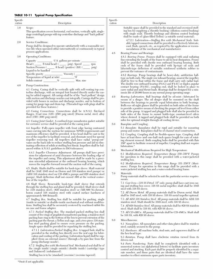
Specifi-cation Description
1.0 Scope:This specification covers horizontal, end suction, vertically split, single-stage centrifugal pumps with top centerline discharge and “back pullout”feature.
2.0 Service Conditions:Pump shall be designed to operate satisfactorily with a reasonable ser-vice life when operated either intermittently or continuously in typicalprocess applications.
3.0 Operating Conditions:Capacity U.S. gallons per minuteHead ( ft total head) ( psig). Speed rpmSuction Pressure ( ft head) (positive) (lift) ( psig)Liquid to be handledSpecific gravity Viscosity ( )Temperature of liquid at inlet °FSolids content % Max. size
4.0 Pump Construction:4.1 Casing. Casing shall be vertically split with self-venting top cen-terline discharge, with an integral foot located directly under the cas-ing for added support. All casings shall be of the “back pullout” designwith suction and discharge nozzles cast integrally. Casings shall be pro-vided with bosses in suction and discharge nozzles, and in bottom ofcasing for gauge taps and drain tap. (Threaded taps with plugs shall beprovided for these features.)4.2 Casing Connections. Connections shall be A.N.S.I. flat-facedflanges. [Cast iron (125) (250) psig rated] [Duron metal, steel, alloysteel (150) (300) psig rated]4.3 Casing Joint Gasket. A confined-type nonasbestos gasket suitablefor corrosive service shall be provided at the casing joint.4.4 Impeller. Fully-open impeller with front edge having contouredvanes curving into the suction for minimum NPSH requirements andmaximum efficiency shall be provided. A hex head shall be cast in theeye of the impeller to facilitate removal, and eliminate need for specialimpeller removing tool. All impellers shall have radial “pump-out”vanes on the back side to reduce stuffing box pressure and aid in elim-inating collection of solids at stuffing box throat. Impellers shall be bal-anced within A.N.S.I. guidelines to ISO tolerances.
4.4.1 Impeller Clearance Adjustment. All pumps shall have provi-sions for adjustment of axial clearance between the leading edge ofthe impeller and casing. This adjustment shall be made by a preci-sion microdial adjustment at the outboard bearing housing, whichmoves the impeller forward toward the suction wall of the casing.
4.5 Shafts. Shafts shall be suitable for hook-type sleeve. Shaft materialshall be (SAE 1045 steel on Duron and 316 stainless steel pumps) or(AISI 316 stainless steel on CD-4MCu pumps and #20 stainless steelpumps). Shaft deflection shall not exceed .005 at the vertical center-line of the impeller.4.6 Shaft Sleeve. Renewable hook-type shaft sleeve that extendsthrough the stuffing box and gland shall be provided. Shaft sleeve shallbe (316 stainless steel), (#20 stainless steel) or (XH-800 Ni-chrome-boron coated 316 stainless steel with coated surface hardness ofapproximately 800 Brinnell).4.7 Stuffing Box. Stuffing box shall be suitable for packing, single(inside or outside) or double-inside mechanical seal without modifica-tions. Stuffing box shall be accurately centered by machined rabbit fitson case and frame adapter.
4.7.1 Packed Stuffing Box. The standard packed stuffing box shallconsist of five rings of graphited nonasbestos packing; a stainless steelpacking base ring in the bottom of the box to prevent extrusion of thepacking past the throat; a Teflon seal cage, and a two-piece 316 stain-less steel packing gland to ensure even pressure on the packing.Ample space shall be provided for repacking the stuffing box.
4.7.1.1 Lubrication-Packed Stuffing Box. A tapped hole shall beprovided in the stuffing box directly over the seal cage for lubri-cation and cooling of the packing. Lubrication liquid shall be sup-plied (from an external source) (through a by-pass line from thepump discharge nozzle).
4.7.2 Stuffing Box with Mechanical Seal. Mechanical seal shall be ofthe (single inside) (single outside) (double inside) (cartridge) typeand (balanced) (unbalanced).Stuffing box is to be (standard) (oversize) (oversize tapered).
Specifi-cation Description
Suitable space shall be provided in the standard and oversized stuff-ing box for supplying a (throttle bushing) (dilution control bushing)with single seals. Throttle bushings and dilution control bushingsshall be made of (glass-filled Teflon) (a suitable metal material).
4.7.2.1 Lubrication—Stuffing Box with Mechanical Seals. Suit-able tapped connections shall be provided to effectively lubricate,cool, flush, quench, etc., as required by the application or recom-mendations of the mechanical seal manufacturer.
4.8 Bearing Frame and Bearings:4.8.1 Bearing Frame. Frames shall be equipped with axial radiatingfins extending the length of the frame to aid in heat dissipation. Frameshall be provided with ductile iron outboard bearing housing. Bothends of the frame shall be provided with lip-type oil seals andlabyrinth-type deflectors of metallic reinforced synthetic rubber toprevent the entrance of contaminants.4.8.2 Bearings. Pump bearings shall be heavy-duty, antifriction ball-type on both ends. The single row inboard bearing, nearest the impeller,shall be free to float within the frame and shall carry only radial load.The double row outboard bearing (F4-G1 and F4-I1) or duplex angularcontact bearing (F4-H1), coupling end, shall be locked in place tocarry radial and axial thrust loads. Bearings shall be designed for a min-imum life of 20,000 hours in any normal pump operating range.
4.9 Bearing Lubrication. Ball bearings shall be oil-mist—lubricated bymeans of a slinger. The oil slinger shall be mounted on the shaftbetween the bearings to provide equal lubrication to both bearings.Bulls-eye oil-sight glasses shall be provided on both sides of the frameto provide a positive means of checking the proper oil level from eitherside of the pump. A tapped and plugged hole shall also be provided inboth sides of the frame to mount bottle-type constant-level oilerswhere desired. A tapped and plugged hole shall be provided on bothsides for optional straight-through oil cooling device.
5.0 Baseplate and Coupling:5.1 Baseplate. Baseplates shall be rigid and suitable for mountingpump and motor. Baseplates shall be of channel steel construction.5.2 Coupling. Coupling shall be flexible-spacer type. Coupling shallhave at least three–and–one-half–inch spacer length for ease of rotat-ing element removal. Both coupling hubs shall be provided with flats180° apart to facilitate removal of impeller. Coupling shall not requirelubrication.*
6.0 Mechanical Modifications Required for High Temperature:6.1 Modifications Required, Temperature Range 250–350°F. Pumpsfor operation in this range shall be provided with a water-jacketedstuffing box.6.2 Modifications Required, Temperature Range 351–550°F (Maxi-mum). Pumps for operation in this range shall be provided with awater-jacketed stuffing box and a water-cooled bearing frame.
7.0 Materials:Pump materials shall be selected to suit the particular service require-ments.7.1 Cast Iron—316 SS Fitted. 15″ only; pump shall have cast iron cas-ing and stuffing box cover. 316 SS metal impeller; shaft shall be 1045steel with 316 SS sleeve.7.2 All Duron Metal. All pump materials shall be Duron metal. Shaftshall be 1045 steel, with 316 SS sleeve. 316 SS metal impeller optional.7.3 All AISI 316 Stainless Steel. All pump materials shall be AISI 316stainless steel. Shaft should be 1045 steel, with 316 SS sleeve.7.4 All #20 Stainless Steel. All pump materials shall be #20 SS stainlesssteel. Shaft shall be 316 SS, with #20 SS sleeve.7.5 All CD-4MCu. All pump materials shall be CD-4MCu. Shaft shallbe 316 SS, with #20 SS sleeve.
8.0 Miscellaneous:8.1 Nameplates. All nameplates and other data plates shall be stainlesssteel, suitably secured to the pump.8.2 Hardware. All machine bolts, stud nuts, and capscrews shall be ofthe hex-head type.8.3 Rotation. Pump shall have clockwise rotation viewed from itsdriven end.8.4 Parts Numbering. Parts shall be completely identified with anumerical system (no alphabetical letters) to facilitate parts inventorycontrol and stocking. Each part shall be properly identified by a sepa-rate number, and those parts that are identical shall have the samenumber to effect minimum spare parts inventory.
TABLE 10-11 Typical Pump Specification
*Omit if not applicable.
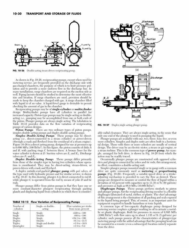
As shown in Fig. 10-26, reciprocating pumps, except when used formetering service, are frequently provided on the discharge side withgas-charged chambers, the purpose of which is to limit pressure pul-sation and to provide a more uniform flow in the discharge line. Inmany installations, surge chambers are required on the suction side aswell. Piping layouts should be studied to determine the most effectivesize and location. If surge chambers are used, provision should bemade to keep the chamber charged with gas. A surge chamber filledwith liquid is of no value. A liquid-level gauge is desirable to permitchecking the amount of gas in the chamber.
Reciprocating pumps may be of single-cylinder or multicylinderdesign. Multicylinder pumps have all cylinders in parallel forincreased capacity. Piston-type pumps may be single-acting or double-acting; i.e., pumping may be accomplished from one or both ends ofthe piston. Plunger pumps are always single-acting. The tabulation inTable 10-12 provides data on the flow variation of reciprocatingpumps of various designs.
Piston Pumps There are two ordinary types of piston pumps,simplex double-acting pumps and duplex double-acting pumps.
Simplex Double-Acting Pumps These pumps may be direct-acting (i.e., direct-connected to a steam cylinder) or power-driven(through a crank and flywheel from the crosshead of a steam engine).Figure 10-26 is a direct-acting pump, designed for use at pressures upto 0.690 MPa (100 lbf/in2). In this figure, the piston consists of disks Aand B, with packing rings C between them. A bronze liner for thewater cylinder is shown at D. Suction valves are E1 and E2. Dischargevalves are F1 and F2.
Duplex Double-Acting Pumps These pumps differ primarilyfrom those of the simplex type in having two cylinders whose opera-tion is coordinated. They may be direct-acting, steam-driven, orpower-driven with crank and flywheel.
A duplex outside-end-packed plunger pump with pot valves, ofthe type used with hydraulic presses and for similar service, is shownin Fig. 10-27. In this drawing, plunger A is direct-connected to rod B,while plunger C is operated from the rod by means of yoke D and tierods.
Plunger pumps differ from piston pumps in that they have one ormore constant-diameter plungers reciprocating through packingglands and displacing liquid from cylinders in which there is consider-
able radial clearance. They are always single-acting, in the sense thatonly one end of the plunger is used in pumping the liquid.
Plunger pumps are available with one, two, three, four, five, or evenmore cylinders. Simplex and duplex units are often built in a horizon-tal design. Those with three or more cylinders are usually of verticaldesign. The driver may be an electric motor, a steam or gas engine, ora steam turbine. This is the common type of power pump. An exam-ple, arranged for belt drive, is shown in Fig. 10-28 from which theaction may be readily traced.
Occasionally plunger pumps are constructed with opposed cylin-ders and plungers connected by yokes and tie rods; this arrangement,in effect, constitutes a double-acting unit.
Simplex plunger pumps mounted singly or in gangs with a commondrive are quite commonly used as metering or proportioningpumps (Fig. 10-29). Frequently a variable-speed drive or a stroke-adjusting mechanism is provided to vary the flow as desired. Thesepumps are designed to measure or control the flow of liquid within adeviation of ±2 percent with capacities up to 11.35 m3/h (50 gal/min)and pressures as high as 68.9 MPa (10,000 lbf/in2).
Diaphragm Pumps These pumps perform similarly to pistonand plunger pumps, but the reciprocating driving member is a flexiblediaphragm fabricated of metal, rubber, or plastic. The chief advantageof this arrangement is the elimination of all packing and seals exposedto the liquid being pumped. This, of course, is an important asset forequipment required to handle hazardous or toxic liquids.
A common type of low-capacity diaphragm pump designed formetering service employs a plunger working in oil to actuate a metal-lic or plastic diaphragm. Built for pressures in excess of 6.895 MPa(1000 lbf/in2) with flow rates up to about 1.135 m3/h (5 gal/min) percylinder, such pumps possess all the characteristics of plunger-typemetering pumps with the added advantage that the pumping head canbe mounted in a remote (even a submerged) location entirely separatefrom the drive.
10-30 TRANSPORT AND STORAGE OF FLUIDS
TABLE 10-12 Flow Variation of Reciprocating Pumps
Number of Single- or double- Flow variation per strokecylinders acting from mean, percent
Single Single +220 to −100Single Double +60 to −100Duplex Single +24.1 to −100Duplex Double +6.1 to −21.5Triplex Single and double +1.8 to −16.9Quintuplex Single +1.8 to −5.2
(a)
(b)
FIG. 10-27 Duplex single-acting plunger pump.
FIG. 10-26 Double-acting steam-driven reciprocating pump.
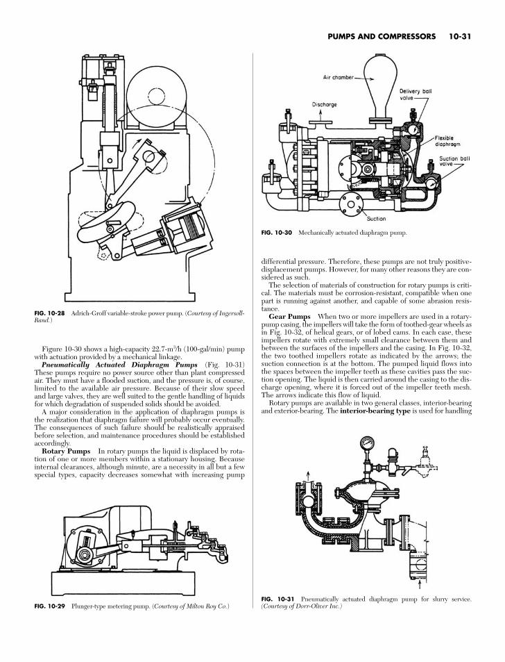
differential pressure. Therefore, these pumps are not truly positive-displacement pumps. However, for many other reasons they are con-sidered as such.
The selection of materials of construction for rotary pumps is criti-cal. The materials must be corrosion-resistant, compatible when onepart is running against another, and capable of some abrasion resis-tance.
Gear Pumps When two or more impellers are used in a rotary-pump casing, the impellers will take the form of toothed-gear wheels asin Fig. 10-32, of helical gears, or of lobed cams. In each case, theseimpellers rotate with extremely small clearance between them andbetween the surfaces of the impellers and the casing. In Fig. 10-32,the two toothed impellers rotate as indicated by the arrows; thesuction connection is at the bottom. The pumped liquid flows intothe spaces between the impeller teeth as these cavities pass the suc-tion opening. The liquid is then carried around the casing to the dis-charge opening, where it is forced out of the impeller teeth mesh.The arrows indicate this flow of liquid.
Rotary pumps are available in two general classes, interior-bearingand exterior-bearing. The interior-bearing type is used for handling
PUMPS AND COMPRESSORS 10-31
FIG. 10-28 Adrich-Groff variable-stroke power pump. (Courtesy of Ingersoll-Rand.)
Figure 10-30 shows a high-capacity 22.7-m3/h (100-gal/min) pumpwith actuation provided by a mechanical linkage.
Pneumatically Actuated Diaphragm Pumps (Fig. 10-31)These pumps require no power source other than plant compressedair. They must have a flooded suction, and the pressure is, of course,limited to the available air pressure. Because of their slow speedand large valves, they are well suited to the gentle handling of liquidsfor which degradation of suspended solids should be avoided.
A major consideration in the application of diaphragm pumps isthe realization that diaphragm failure will probably occur eventually.The consequences of such failure should be realistically appraisedbefore selection, and maintenance procedures should be establishedaccordingly.
Rotary Pumps In rotary pumps the liquid is displaced by rota-tion of one or more members within a stationary housing. Becauseinternal clearances, although minute, are a necessity in all but a fewspecial types, capacity decreases somewhat with increasing pump
FIG. 10-29 Plunger-type metering pump. (Courtesy of Milton Roy Co.)
FIG. 10-30 Mechanically actuated diaphragm pump.
FIG. 10-31 Pneumatically actuated diaphragm pump for slurry service.(Courtesy of Dorr-Oliver Inc.)
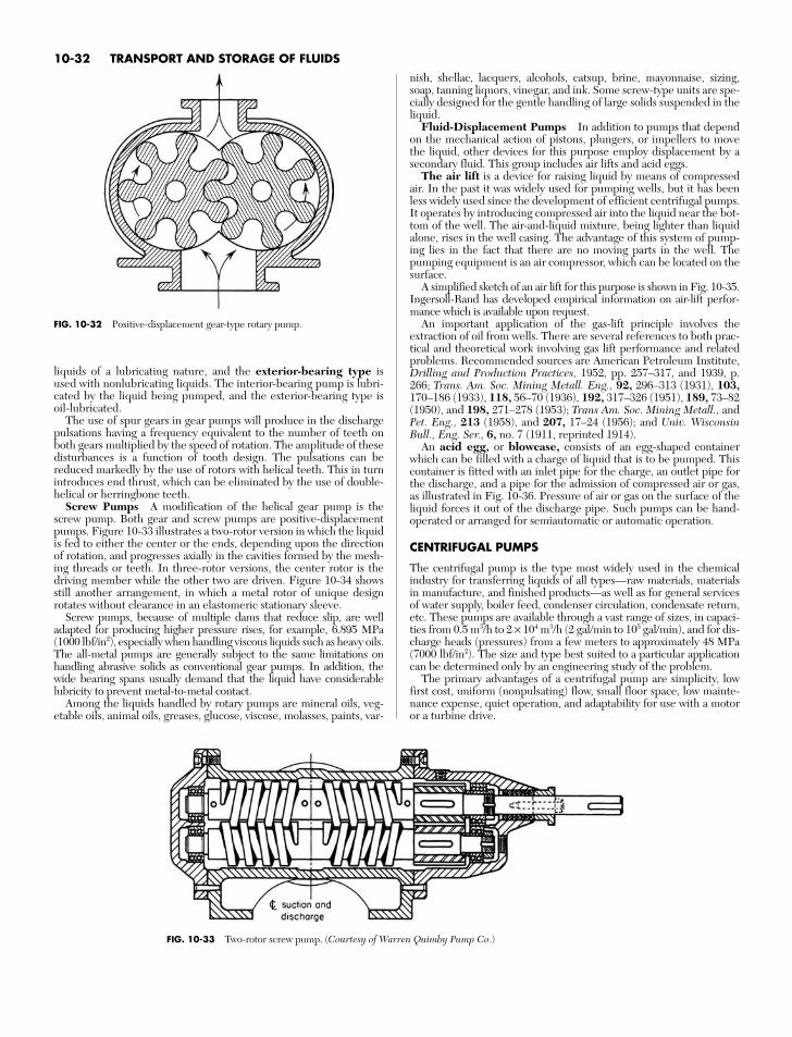
liquids of a lubricating nature, and the exterior-bearing type isused with nonlubricating liquids. The interior-bearing pump is lubri-cated by the liquid being pumped, and the exterior-bearing type isoil-lubricated.
The use of spur gears in gear pumps will produce in the dischargepulsations having a frequency equivalent to the number of teeth onboth gears multiplied by the speed of rotation. The amplitude of thesedisturbances is a function of tooth design. The pulsations can bereduced markedly by the use of rotors with helical teeth. This in turnintroduces end thrust, which can be eliminated by the use of double-helical or herringbone teeth.
Screw Pumps A modification of the helical gear pump is thescrew pump. Both gear and screw pumps are positive-displacementpumps. Figure 10-33 illustrates a two-rotor version in which the liquidis fed to either the center or the ends, depending upon the directionof rotation, and progresses axially in the cavities formed by the mesh-ing threads or teeth. In three-rotor versions, the center rotor is thedriving member while the other two are driven. Figure 10-34 showsstill another arrangement, in which a metal rotor of unique designrotates without clearance in an elastomeric stationary sleeve.
Screw pumps, because of multiple dams that reduce slip, are welladapted for producing higher pressure rises, for example, 6.895 MPa(1000 lbf/in2), especially when handling viscous liquids such as heavy oils.The all-metal pumps are generally subject to the same limitations onhandling abrasive solids as conventional gear pumps. In addition, thewide bearing spans usually demand that the liquid have considerablelubricity to prevent metal-to-metal contact.
Among the liquids handled by rotary pumps are mineral oils, veg-etable oils, animal oils, greases, glucose, viscose, molasses, paints, var-
10-32 TRANSPORT AND STORAGE OF FLUIDS
FIG. 10-32 Positive-displacement gear-type rotary pump.
FIG. 10-33 Two-rotor screw pump. (Courtesy of Warren Quimby Pump Co.)
nish, shellac, lacquers, alcohols, catsup, brine, mayonnaise, sizing,soap, tanning liquors, vinegar, and ink. Some screw-type units are spe-cially designed for the gentle handling of large solids suspended in theliquid.
Fluid-Displacement Pumps In addition to pumps that dependon the mechanical action of pistons, plungers, or impellers to movethe liquid, other devices for this purpose employ displacement by asecondary fluid. This group includes air lifts and acid eggs.
The air lift is a device for raising liquid by means of compressedair. In the past it was widely used for pumping wells, but it has beenless widely used since the development of efficient centrifugal pumps.It operates by introducing compressed air into the liquid near the bot-tom of the well. The air-and-liquid mixture, being lighter than liquidalone, rises in the well casing. The advantage of this system of pump-ing lies in the fact that there are no moving parts in the well. Thepumping equipment is an air compressor, which can be located on thesurface.
A simplified sketch of an air lift for this purpose is shown in Fig. 10-35.Ingersoll-Rand has developed empirical information on air-lift perfor-mance which is available upon request.
An important application of the gas-lift principle involves theextraction of oil from wells. There are several references to both prac-tical and theoretical work involving gas lift performance and relatedproblems. Recommended sources are American Petroleum Institute,Drilling and Production Practices, 1952, pp. 257–317, and 1939, p.266; Trans. Am. Soc. Mining Metall. Eng., 92, 296–313 (1931), 103,170–186 (1933), 118, 56–70 (1936), 192, 317–326 (1951), 189, 73–82(1950), and 198, 271–278 (1953); Trans Am. Soc. Mining Metall., andPet. Eng., 213 (1958), and 207, 17–24 (1956); and Univ. WisconsinBull., Eng. Ser., 6, no. 7 (1911, reprinted 1914).
An acid egg, or blowcase, consists of an egg-shaped containerwhich can be filled with a charge of liquid that is to be pumped. Thiscontainer is fitted with an inlet pipe for the charge, an outlet pipe forthe discharge, and a pipe for the admission of compressed air or gas,as illustrated in Fig. 10-36. Pressure of air or gas on the surface of theliquid forces it out of the discharge pipe. Such pumps can be hand-operated or arranged for semiautomatic or automatic operation.
CENTRIFUGAL PUMPS
The centrifugal pump is the type most widely used in the chemicalindustry for transferring liquids of all types—raw materials, materialsin manufacture, and finished products—as well as for general servicesof water supply, boiler feed, condenser circulation, condensate return,etc. These pumps are available through a vast range of sizes, in capaci-ties from 0.5 m3/h to 2 × 10⁴ m3/h (2 gal/min to 105 gal/min), and for dis-charge heads (pressures) from a few meters to approximately 48 MPa(7000 lbf/in2). The size and type best suited to a particular applicationcan be determined only by an engineering study of the problem.
The primary advantages of a centrifugal pump are simplicity, lowfirst cost, uniform (nonpulsating) flow, small floor space, low mainte-nance expense, quiet operation, and adaptability for use with a motoror a turbine drive.
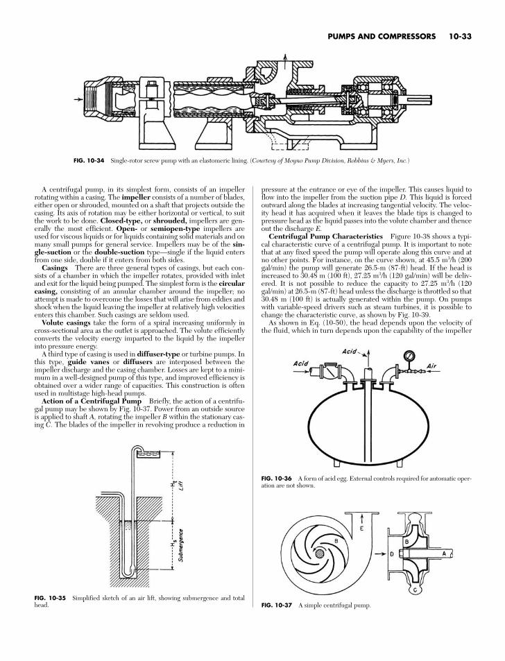
A centrifugal pump, in its simplest form, consists of an impellerrotating within a casing. The impeller consists of a number of blades,either open or shrouded, mounted on a shaft that projects outside thecasing. Its axis of rotation may be either horizontal or vertical, to suitthe work to be done. Closed-type, or shrouded, impellers are gen-erally the most efficient. Open- or semiopen-type impellers areused for viscous liquids or for liquids containing solid materials and onmany small pumps for general service. Impellers may be of the sin-gle-suction or the double-suction type—single if the liquid entersfrom one side, double if it enters from both sides.
Casings There are three general types of casings, but each con-sists of a chamber in which the impeller rotates, provided with inletand exit for the liquid being pumped. The simplest form is the circularcasing, consisting of an annular chamber around the impeller; noattempt is made to overcome the losses that will arise from eddies andshock when the liquid leaving the impeller at relatively high velocitiesenters this chamber. Such casings are seldom used.
Volute casings take the form of a spiral increasing uniformly incross-sectional area as the outlet is approached. The volute efficientlyconverts the velocity energy imparted to the liquid by the impellerinto pressure energy.
A third type of casing is used in diffuser-type or turbine pumps. Inthis type, guide vanes or diffusers are interposed between theimpeller discharge and the casing chamber. Losses are kept to a mini-mum in a well-designed pump of this type, and improved efficiency isobtained over a wider range of capacities. This construction is oftenused in multistage high-head pumps.
Action of a Centrifugal Pump Briefly, the action of a centrifu-gal pump may be shown by Fig. 10-37. Power from an outside sourceis applied to shaft A, rotating the impeller B within the stationary cas-ing C. The blades of the impeller in revolving produce a reduction in
pressure at the entrance or eye of the impeller. This causes liquid toflow into the impeller from the suction pipe D. This liquid is forcedoutward along the blades at increasing tangential velocity. The veloc-ity head it has acquired when it leaves the blade tips is changed topressure head as the liquid passes into the volute chamber and thenceout the discharge E.
Centrifugal Pump Characteristics Figure 10-38 shows a typi-cal characteristic curve of a centrifugal pump. It is important to notethat at any fixed speed the pump will operate along this curve and atno other points. For instance, on the curve shown, at 45.5 m3/h (200gal/min) the pump will generate 26.5-m (87-ft) head. If the head isincreased to 30.48 m (100 ft), 27.25 m3/h (120 gal/min) will be deliv-ered. It is not possible to reduce the capacity to 27.25 m3/h (120gal/min) at 26.5-m (87-ft) head unless the discharge is throttled so that30.48 m (100 ft) is actually generated within the pump. On pumpswith variable-speed drivers such as steam turbines, it is possible tochange the characteristic curve, as shown by Fig. 10-39.
As shown in Eq. (10-50), the head depends upon the velocity ofthe fluid, which in turn depends upon the capability of the impeller
PUMPS AND COMPRESSORS 10-33
FIG. 10-34 Single-rotor screw pump with an elastomeric lining. (Courtesy of Moyno Pump Division, Robbins & Myers, Inc.)
FIG. 10-35 Simplified sketch of an air lift, showing submergence and totalhead.
FIG. 10-36 A form of acid egg. External controls required for automatic oper-ation are not shown.
FIG. 10-37 A simple centrifugal pump.
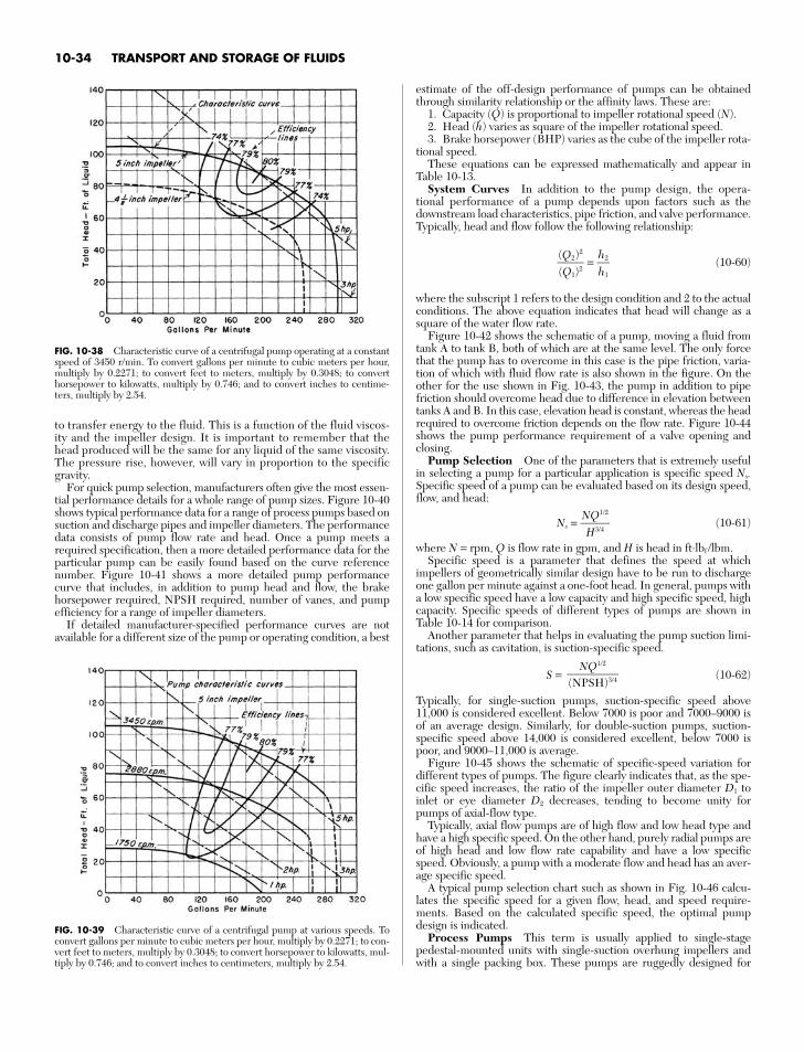
to transfer energy to the fluid. This is a function of the fluid viscos-ity and the impeller design. It is important to remember that thehead produced will be the same for any liquid of the same viscosity.The pressure rise, however, will vary in proportion to the specificgravity.
For quick pump selection, manufacturers often give the most essen-tial performance details for a whole range of pump sizes. Figure 10-40shows typical performance data for a range of process pumps based onsuction and discharge pipes and impeller diameters. The performancedata consists of pump flow rate and head. Once a pump meets arequired specification, then a more detailed performance data for theparticular pump can be easily found based on the curve referencenumber. Figure 10-41 shows a more detailed pump performancecurve that includes, in addition to pump head and flow, the brakehorsepower required, NPSH required, number of vanes, and pumpefficiency for a range of impeller diameters.
If detailed manufacturer-specified performance curves are notavailable for a different size of the pump or operating condition, a best
estimate of the off-design performance of pumps can be obtainedthrough similarity relationship or the affinity laws. These are:
1. Capacity (Q) is proportional to impeller rotational speed (N).2. Head (h) varies as square of the impeller rotational speed.3. Brake horsepower (BHP) varies as the cube of the impeller rota-
tional speed.These equations can be expressed mathematically and appear in
Table 10-13.System Curves In addition to the pump design, the opera-
tional performance of a pump depends upon factors such as thedownstream load characteristics, pipe friction, and valve performance.Typically, head and flow follow the following relationship:
= (10-60)
where the subscript 1 refers to the design condition and 2 to the actualconditions. The above equation indicates that head will change as asquare of the water flow rate.
Figure 10-42 shows the schematic of a pump, moving a fluid fromtank A to tank B, both of which are at the same level. The only forcethat the pump has to overcome in this case is the pipe friction, varia-tion of which with fluid flow rate is also shown in the figure. On theother for the use shown in Fig. 10-43, the pump in addition to pipefriction should overcome head due to difference in elevation betweentanks A and B. In this case, elevation head is constant, whereas the headrequired to overcome friction depends on the flow rate. Figure 10-44shows the pump performance requirement of a valve opening andclosing.
Pump Selection One of the parameters that is extremely usefulin selecting a pump for a particular application is specific speed Ns.Specific speed of a pump can be evaluated based on its design speed,flow, and head:
Ns = (10-61)
where N = rpm, Q is flow rate in gpm, and H is head in ft⋅lbf /lbm.Specific speed is a parameter that defines the speed at which
impellers of geometrically similar design have to be run to dischargeone gallon per minute against a one-foot head. In general, pumps witha low specific speed have a low capacity and high specific speed, highcapacity. Specific speeds of different types of pumps are shown inTable 10-14 for comparison.
Another parameter that helps in evaluating the pump suction limi-tations, such as cavitation, is suction-specific speed.
S = (10-62)
Typically, for single-suction pumps, suction-specific speed above11,000 is considered excellent. Below 7000 is poor and 7000–9000 isof an average design. Similarly, for double-suction pumps, suction-specific speed above 14,000 is considered excellent, below 7000 ispoor, and 9000–11,000 is average.
Figure 10-45 shows the schematic of specific-speed variation fordifferent types of pumps. The figure clearly indicates that, as the spe-cific speed increases, the ratio of the impeller outer diameter D1 toinlet or eye diameter D2 decreases, tending to become unity forpumps of axial-flow type.
Typically, axial flow pumps are of high flow and low head type andhave a high specific speed. On the other hand, purely radial pumps areof high head and low flow rate capability and have a low specificspeed. Obviously, a pump with a moderate flow and head has an aver-age specific speed.
A typical pump selection chart such as shown in Fig. 10-46 calcu-lates the specific speed for a given flow, head, and speed require-ments. Based on the calculated specific speed, the optimal pumpdesign is indicated.
Process Pumps This term is usually applied to single-stagepedestal-mounted units with single-suction overhung impellers andwith a single packing box. These pumps are ruggedly designed for
NQ1/2
(NPSH)3/4
NQ1/2
H3/4
h2h1
(Q2)2
(Q1)2
10-34 TRANSPORT AND STORAGE OF FLUIDS
FIG. 10-38 Characteristic curve of a centrifugal pump operating at a constantspeed of 3450 r/min. To convert gallons per minute to cubic meters per hour,multiply by 0.2271; to convert feet to meters, multiply by 0.3048; to converthorsepower to kilowatts, multiply by 0.746; and to convert inches to centime-ters, multiply by 2.54.
FIG. 10-39 Characteristic curve of a centrifugal pump at various speeds. Toconvert gallons per minute to cubic meters per hour, multiply by 0.2271; to con-vert feet to meters, multiply by 0.3048; to convert horsepower to kilowatts, mul-tiply by 0.746; and to convert inches to centimeters, multiply by 2.54.
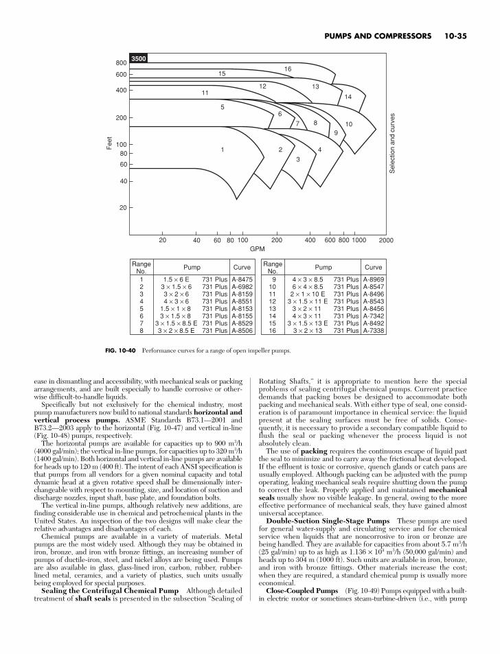
ease in dismantling and accessibility, with mechanical seals or packingarrangements, and are built especially to handle corrosive or other-wise difficult-to-handle liquids.
Specifically but not exclusively for the chemical industry, mostpump manufacturers now build to national standards horizontal andvertical process pumps. ASME Standards B73.1—2001 andB73.2—2003 apply to the horizontal (Fig. 10-47) and vertical in-line(Fig. 10-48) pumps, respectively.
The horizontal pumps are available for capacities up to 900 m3/h(4000 gal/min); the vertical in-line pumps, for capacities up to 320 m3/h(1400 gal/min). Both horizontal and vertical in-line pumps are availablefor heads up to 120 m (400 ft). The intent of each ANSI specification isthat pumps from all vendors for a given nominal capacity and totaldynamic head at a given rotative speed shall be dimensionally inter-changeable with respect to mounting, size, and location of suction anddischarge nozzles, input shaft, base plate, and foundation bolts.
The vertical in-line pumps, although relatively new additions, arefinding considerable use in chemical and petrochemical plants in theUnited States. An inspection of the two designs will make clear therelative advantages and disadvantages of each.
Chemical pumps are available in a variety of materials. Metalpumps are the most widely used. Although they may be obtained iniron, bronze, and iron with bronze fittings, an increasing number ofpumps of ductile-iron, steel, and nickel alloys are being used. Pumpsare also available in glass, glass-lined iron, carbon, rubber, rubber-lined metal, ceramics, and a variety of plastics, such units usuallybeing employed for special purposes.
Sealing the Centrifugal Chemical Pump Although detailedtreatment of shaft seals is presented in the subsection “Sealing of
Rotating Shafts,” it is appropriate to mention here the specialproblems of sealing centrifugal chemical pumps. Current practicedemands that packing boxes be designed to accommodate bothpacking and mechanical seals. With either type of seal, one consid-eration is of paramount importance in chemical service: the liquidpresent at the sealing surfaces must be free of solids. Conse-quently, it is necessary to provide a secondary compatible liquid toflush the seal or packing whenever the process liquid is notabsolutely clean.
The use of packing requires the continuous escape of liquid pastthe seal to minimize and to carry away the frictional heat developed.If the effluent is toxic or corrosive, quench glands or catch pans areusually employed. Although packing can be adjusted with the pumpoperating, leaking mechanical seals require shutting down the pumpto correct the leak. Properly applied and maintained mechanicalseals usually show no visible leakage. In general, owing to the moreeffective performance of mechanical seals, they have gained almostuniversal acceptance.
Double-Suction Single-Stage Pumps These pumps are usedfor general water-supply and circulating service and for chemicalservice when liquids that are noncorrosive to iron or bronze arebeing handled. They are available for capacities from about 5.7 m3/h(25 gal/min) up to as high as 1.136 × 10⁴ m3/h (50,000 gal/min) andheads up to 304 m (1000 ft). Such units are available in iron, bronze,and iron with bronze fittings. Other materials increase the cost;when they are required, a standard chemical pump is usually moreeconomical.
Close-Coupled Pumps (Fig. 10-49) Pumps equipped with a built-in electric motor or sometimes steam-turbine-driven (i.e., with pump
PUMPS AND COMPRESSORS 10-35
80
60
40
100
200
400
600
800
20
20
RangeNo.
CurvePump
12345678
731 Plus731 Plus731 Plus731 Plus731 Plus731 Plus731 Plus731 Plus
A-8475A-6982A-8159A-8551A-8153A-8155A-8529A-8506
1.5 × 6 E3 × 1.5 × 63 × 2 × 64 × 3 × 6
1.5 × 1 × 8 3 × 1.5 × 8
3 × 1.5 × 8.5 E3 × 2 × 8.5 E
100GPM
200 400 600 800 100040 60
Fee
t
Sel
ectio
n an
d cu
rves
80 2000
3500
15
1211
56
7 8
9
4
3
21
10
13
14
16
RangeNo.
CurvePump
910111213141516
731 Plus731 Plus731 Plus731 Plus731 Plus731 Plus731 Plus731 Plus
A-8969A-8547A-8496A-8543A-8456A-7342A-8492A-7338
4 × 3 × 8.56 × 4 × 8.5
2 × 1 × 10 E3 × 1.5 × 11 E
3 × 2 × 11 4 × 3 × 11
3 × 1.5 × 13 E3 × 2 × 13
FIG. 10-40 Performance curves for a range of open impeller pumps.
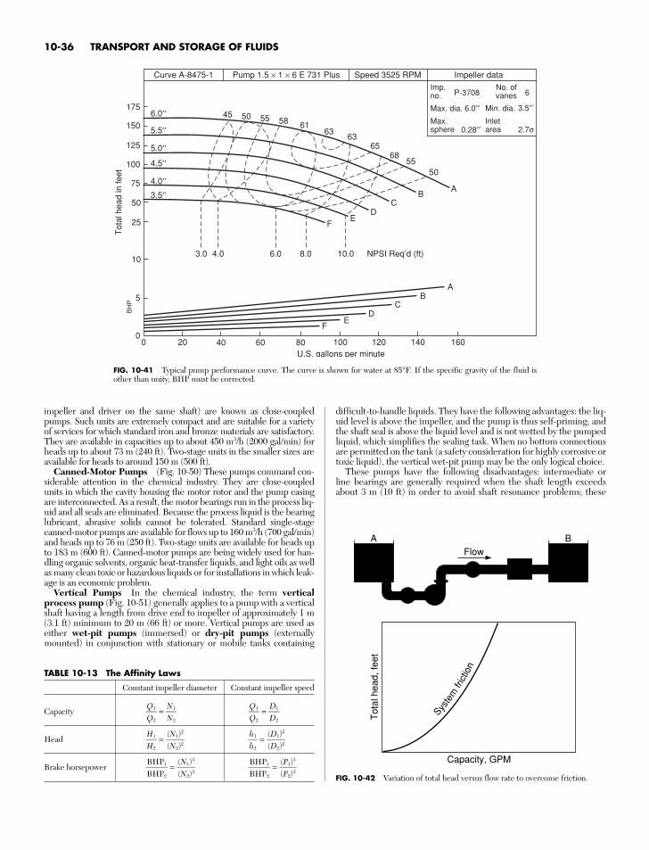
impeller and driver on the same shaft) are known as close-coupledpumps. Such units are extremely compact and are suitable for a varietyof services for which standard iron and bronze materials are satisfactory.They are available in capacities up to about 450 m3/h (2000 gal/min) forheads up to about 73 m (240 ft). Two-stage units in the smaller sizes areavailable for heads to around 150 m (500 ft).
Canned-Motor Pumps (Fig. 10-50) These pumps command con-siderable attention in the chemical industry. They are close-coupledunits in which the cavity housing the motor rotor and the pump casingare interconnected. As a result, the motor bearings run in the process liq-uid and all seals are eliminated. Because the process liquid is the bearinglubricant, abrasive solids cannot be tolerated. Standard single-stagecanned-motor pumps are available for flows up to 160 m3/h (700 gal/min)and heads up to 76 m (250 ft). Two-stage units are available for heads upto 183 m (600 ft). Canned-motor pumps are being widely used for han-dling organic solvents, organic heat-transfer liquids, and light oils as wellas many clean toxic or hazardous liquids or for installations in which leak-age is an economic problem.
Vertical Pumps In the chemical industry, the term verticalprocess pump (Fig. 10-51) generally applies to a pump with a verticalshaft having a length from drive end to impeller of approximately 1 m(3.1 ft) minimum to 20 m (66 ft) or more. Vertical pumps are used aseither wet-pit pumps (immersed) or dry-pit pumps (externallymounted) in conjunction with stationary or mobile tanks containing
10-36 TRANSPORT AND STORAGE OF FLUIDS
10
25
50
75
100
125
150
175
Curve A-8475-1
5
00 20 100
U.S. gallons per minute120 140 16040 60
Tot
al h
ead
in fe
etB
HP
80
AB
CD
E
3.0 4.0 6.0 8.0 10.0 NPSI Req’d (ft)
F
AB
CD
EF
6.0′′ 45 50 55 58 6163
6365
6855
50
5.5′′
5.0′′
4.5′′
4.0′′
3.5′′
Pump 1.5 × 1 × 6 E 731 Plus Speed 3525 RPM Impeller dataImp.no.
Max. dia. 6.0′′ Max.sphere
No. ofvanes
Inletarea 2.7σ
3.5′′
6P-3708
Min. dia.
0.28′′
FIG. 10-41 Typical pump performance curve. The curve is shown for water at 85°F. If the specific gravity of the fluid isother than unity, BHP must be corrected.
TABLE 10-13 The Affinity Laws
Constant impeller diameter Constant impeller speed
Capacity = =
Head = =
Brake horsepower = = (P1)3
(P2)3
BHP1BHP2
(N1)3
(N2)3
BHP1BHP2
(D1)2
(D2)2
h1h2
(N1)2
(N2)2
H1H2
D1D2
Q1Q2
N1N2
Q1Q2
Flow
Capacity, GPM
Tot
al h
ead,
feet
A B
Syste
mfri
ctio
n
FIG. 10-42 Variation of total head versus flow rate to overcome friction.
difficult-to-handle liquids. They have the following advantages: the liq-uid level is above the impeller, and the pump is thus self-priming; andthe shaft seal is above the liquid level and is not wetted by the pumpedliquid, which simplifies the sealing task. When no bottom connectionsare permitted on the tank (a safety consideration for highly corrosive ortoxic liquid), the vertical wet-pit pump may be the only logical choice.
These pumps have the following disadvantages: intermediate orline bearings are generally required when the shaft length exceedsabout 3 m (10 ft) in order to avoid shaft resonance problems; these
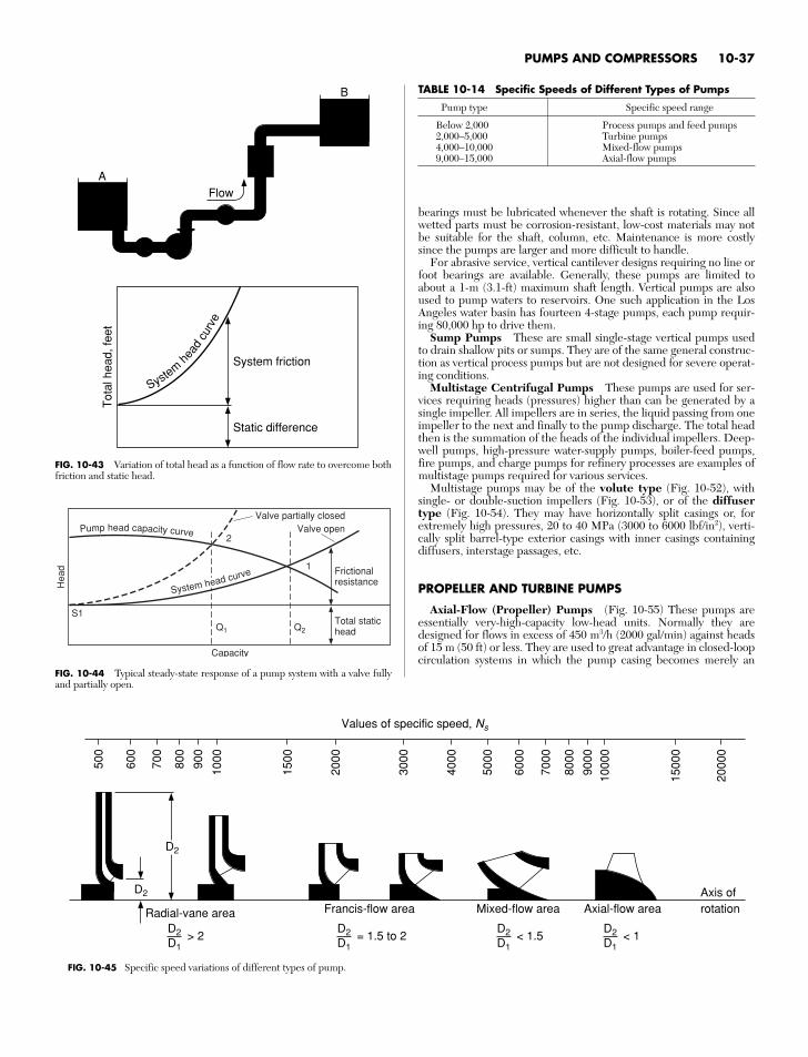
bearings must be lubricated whenever the shaft is rotating. Since allwetted parts must be corrosion-resistant, low-cost materials may notbe suitable for the shaft, column, etc. Maintenance is more costlysince the pumps are larger and more difficult to handle.
For abrasive service, vertical cantilever designs requiring no line orfoot bearings are available. Generally, these pumps are limited toabout a 1-m (3.1-ft) maximum shaft length. Vertical pumps are alsoused to pump waters to reservoirs. One such application in the LosAngeles water basin has fourteen 4-stage pumps, each pump requir-ing 80,000 hp to drive them.
Sump Pumps These are small single-stage vertical pumps usedto drain shallow pits or sumps. They are of the same general construc-tion as vertical process pumps but are not designed for severe operat-ing conditions.
Multistage Centrifugal Pumps These pumps are used for ser-vices requiring heads (pressures) higher than can be generated by asingle impeller. All impellers are in series, the liquid passing from oneimpeller to the next and finally to the pump discharge. The total headthen is the summation of the heads of the individual impellers. Deep-well pumps, high-pressure water-supply pumps, boiler-feed pumps,fire pumps, and charge pumps for refinery processes are examples ofmultistage pumps required for various services.
Multistage pumps may be of the volute type (Fig. 10-52), withsingle- or double-suction impellers (Fig. 10-53), or of the diffusertype (Fig. 10-54). They may have horizontally split casings or, forextremely high pressures, 20 to 40 MPa (3000 to 6000 lbf/in2), verti-cally split barrel-type exterior casings with inner casings containingdiffusers, interstage passages, etc.
PROPELLER AND TURBINE PUMPS
Axial-Flow (Propeller) Pumps (Fig. 10-55) These pumps areessentially very-high-capacity low-head units. Normally they aredesigned for flows in excess of 450 m3/h (2000 gal/min) against headsof 15 m (50 ft) or less. They are used to great advantage in closed-loopcirculation systems in which the pump casing becomes merely an
PUMPS AND COMPRESSORS 10-37
Flow
Static difference
System friction
Tot
al h
ead,
feet
A
B
System
head
curv
e
FIG. 10-43 Variation of total head as a function of flow rate to overcome bothfriction and static head.
Total statichead
Frictionalresistance
Valve partially closed
1
2
Q2Q1
S1
Hea
d
Pump head capacity curve Valve open
Capacity
System head curve
FIG. 10-44 Typical steady-state response of a pump system with a valve fullyand partially open.
TABLE 10-14 Specific Speeds of Different Types of Pumps
Pump type Specific speed range
Below 2,000 Process pumps and feed pumps2,000–5,000 Turbine pumps4,000–10,000 Mixed-flow pumps9,000–15,000 Axial-flow pumps
Values of specific speed, Ns
500
600
700
800
900
1000
1500
2000
3000
4000
5000
6000
7000
8000
9000
1000
0
1500
0
2000
0
D2
D2
D2D1
> 2D2D1
= 1.5 to 2D2D1
< 1.5D2D1
< 1
Radial-vane area
Axis ofrotationAxial-flow areaMixed-flow areaFrancis-flow area
FIG. 10-45 Specific speed variations of different types of pump.
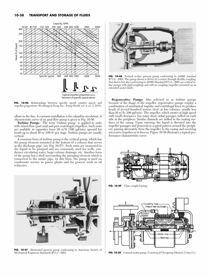
Regenerative Pumps Also referred to as turbine pumpsbecause of the shape of the impeller, regenerative pumps employ acombination of mechanical impulse and centrifugal force to produceheads of several hundred meters (feet) at low volumes, usually lessthan 20 m3/h (100 gal/min). The impeller, which rotates at high speedwith small clearances, has many short radial passages milled on eachside at the periphery. Similar channels are milled in the mating sur-faces of the casing. Upon entering, the liquid is directed into theimpeller passages and proceeds in a spiral pattern around the periph-ery, passing alternately from the impeller to the casing and receivingsuccessive impulses as it does so. Figure 10-58 illustrates a typical per-formance-characteristic curve.
10-38 TRANSPORT AND STORAGE OF FLUIDSH
ead,
ft o
f liq
uid
970 rpm
970 rpm
1150 rpm
1150 rpm
1450 rpm
1450 rpm
1770 rpm
1770 rpm
2950 rpm
2950 rpm
3550 rpm
3550 rpm
970 rpm
1150 rpm
1450 rpm
1770 rpm
2950 rpm
3550 rpm
50400
300
200
150
100
80
605040
30
60 80 100 150 200 300 400Capacity, GPM
600 800 1000 2000 4000
400Specific speed
Typical impeller proportion as afunction of specific speed above
600 800 1000 2000 4000
FIG. 10-46 Relationships between specific speed, rotative speed, andimpeller proportions (Worthington Pump Inc., Pump World, vol. 4, no. 2, 1978).
FIG. 10-47 Horizontal process pump conforming to American Society ofMechanical Engineers Standards B73.1—2001.
elbow in the line. A common installation is for calandria circulation. Acharacteristic curve of an axial-flow pump is given in Fig. 10-56.
Turbine Pumps The term “turbine pump” is applied to unitswith mixed-flow (part axial and part centrifugal) impellers. Such unitsare available in capacities from 20 m3/h (100 gal/min) upward forheads up to about 30 m (100 ft) per stage. Turbine pumps are usuallyvertical.
A common form of turbine pump is the vertical pump, which hasthe pump element mounted at the bottom of a column that servesas the discharge pipe (see Fig. 10-57). Such units are immersed inthe liquid to be pumped and are commonly used for wells, con-denser circulating water, large-volume drainage, etc. Another formof the pump has a shell surrounding the pumping element which isconnected to the intake pipe. In this form, the pump is used oncondensate service in power plants and for process work in oilrefineries.
FIG. 10-48 Vertical in-line process pump conforming to ASME standardB73.2—2003. The pump shown is driven by a motor through flexible coupling.Not shown but also conforming to ASME Standard B73.2—2003 are vertical in-line pumps with rigid couplings and with no coupling (impeller-mounted on anextended motor shaft).
FIG. 10-49 Close-coupled pump.
FIG. 10-50 Canned-motor pump. (Courtesy of Chempump Division, Crane Co.)
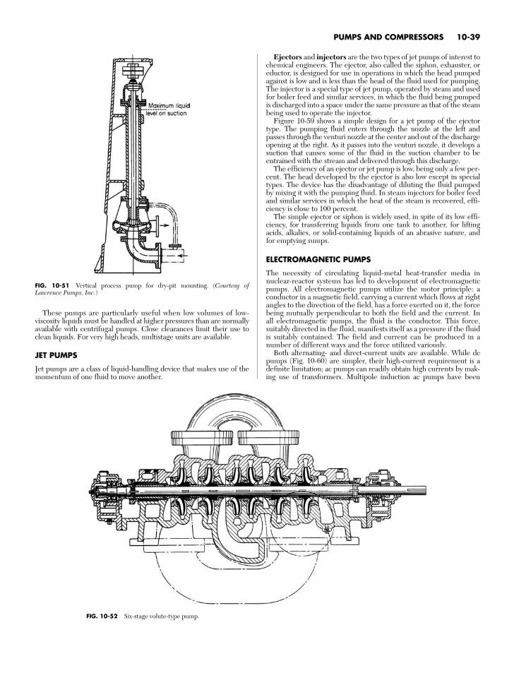
PUMPS AND COMPRESSORS 10-39
FIG. 10-51 Vertical process pump for dry-pit mounting. (Courtesy ofLawrence Pumps, Inc.)
These pumps are particularly useful when low volumes of low-viscosity liquids must be handled at higher pressures than are normallyavailable with centrifugal pumps. Close clearances limit their use toclean liquids. For very high heads, multistage units are available.
JET PUMPS
Jet pumps are a class of liquid-handling device that makes use of themomentum of one fluid to move another.
FIG. 10-52 Six-stage volute-type pump.
Ejectors and injectors are the two types of jet pumps of interest tochemical engineers. The ejector, also called the siphon, exhauster, oreductor, is designed for use in operations in which the head pumpedagainst is low and is less than the head of the fluid used for pumping.The injector is a special type of jet pump, operated by steam and usedfor boiler feed and similar services, in which the fluid being pumpedis discharged into a space under the same pressure as that of the steambeing used to operate the injector.
Figure 10-59 shows a simple design for a jet pump of the ejectortype. The pumping fluid enters through the nozzle at the left andpasses through the venturi nozzle at the center and out of the dischargeopening at the right. As it passes into the venturi nozzle, it develops asuction that causes some of the fluid in the suction chamber to beentrained with the stream and delivered through this discharge.
The efficiency of an ejector or jet pump is low, being only a few per-cent. The head developed by the ejector is also low except in specialtypes. The device has the disadvantage of diluting the fluid pumpedby mixing it with the pumping fluid. In steam injectors for boiler feedand similar services in which the heat of the steam is recovered, effi-ciency is close to 100 percent.
The simple ejector or siphon is widely used, in spite of its low effi-ciency, for transferring liquids from one tank to another, for liftingacids, alkalies, or solid-containing liquids of an abrasive nature, andfor emptying sumps.
ELECTROMAGNETIC PUMPS
The necessity of circulating liquid-metal heat-transfer media innuclear-reactor systems has led to development of electromagneticpumps. All electromagnetic pumps utilize the motor principle: aconductor in a magnetic field, carrying a current which flows at rightangles to the direction of the field, has a force exerted on it, the forcebeing mutually perpendicular to both the field and the current. Inall electromagnetic pumps, the fluid is the conductor. This force,suitably directed in the fluid, manifests itself as a pressure if the fluidis suitably contained. The field and current can be produced in anumber of different ways and the force utilized variously.
Both alternating- and direct-current units are available. While dcpumps (Fig. 10-60) are simpler, their high-current requirement is adefinite limitation; ac pumps can readily obtain high currents by mak-ing use of transformers. Multipole induction ac pumps have been
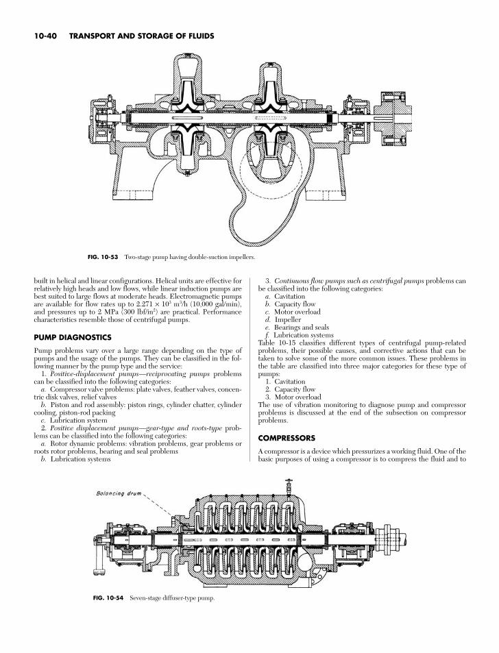
built in helical and linear configurations. Helical units are effective forrelatively high heads and low flows, while linear induction pumps arebest suited to large flows at moderate heads. Electromagnetic pumpsare available for flow rates up to 2.271 × 10³ m3/h (10,000 gal/min),and pressures up to 2 MPa (300 lbf/in2) are practical. Performancecharacteristics resemble those of centrifugal pumps.
PUMP DIAGNOSTICS
Pump problems vary over a large range depending on the type ofpumps and the usage of the pumps. They can be classified in the fol-lowing manner by the pump type and the service:
1. Positive-displacement pumps—reciprocating pumps problemscan be classified into the following categories:
a. Compressor valve problems: plate valves, feather valves, concen-tric disk valves, relief valves
b. Piston and rod assembly: piston rings, cylinder chatter, cylindercooling, piston-rod packing
c. Lubrication system2. Positive displacement pumps—gear-type and roots-type prob-
lems can be classified into the following categories:a. Rotor dynamic problems: vibration problems, gear problems or
roots rotor problems, bearing and seal problemsb. Lubrication systems
3. Continuous flow pumps such as centrifugal pumps problems canbe classified into the following categories:
a. Cavitationb. Capacity flowc. Motor overloadd. Impellere. Bearings and sealsf. Lubrication systems
Table 10-15 classifies different types of centrifugal pump-relatedproblems, their possible causes, and corrective actions that can betaken to solve some of the more common issues. These problems inthe table are classified into three major categories for these type ofpumps:
1. Cavitation2. Capacity flow3. Motor overload
The use of vibration monitoring to diagnose pump and compressorproblems is discussed at the end of the subsection on compressorproblems.
COMPRESSORS
A compressor is a device which pressurizes a working fluid. One of thebasic purposes of using a compressor is to compress the fluid and to
10-40 TRANSPORT AND STORAGE OF FLUIDS
FIG. 10-53 Two-stage pump having double-suction impellers.
FIG. 10-54 Seven-stage diffuser-type pump.
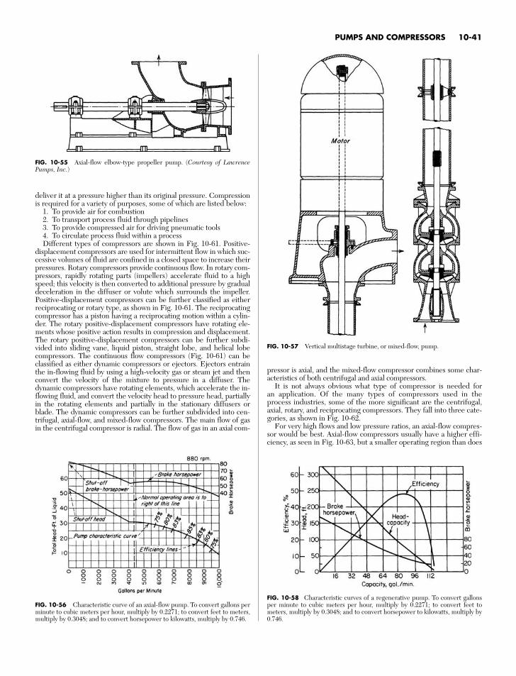
deliver it at a pressure higher than its original pressure. Compressionis required for a variety of purposes, some of which are listed below:
1. To provide air for combustion2. To transport process fluid through pipelines3. To provide compressed air for driving pneumatic tools4. To circulate process fluid within a processDifferent types of compressors are shown in Fig. 10-61. Positive-
displacement compressors are used for intermittent flow in which suc-cessive volumes of fluid are confined in a closed space to increase theirpressures. Rotary compressors provide continuous flow. In rotary com-pressors, rapidly rotating parts (impellers) accelerate fluid to a highspeed; this velocity is then converted to additional pressure by gradualdeceleration in the diffuser or volute which surrounds the impeller.Positive-displacement compressors can be further classified as eitherreciprocating or rotary type, as shown in Fig. 10-61. The reciprocatingcompressor has a piston having a reciprocating motion within a cylin-der. The rotary positive-displacement compressors have rotating ele-ments whose positive action results in compression and displacement.The rotary positive-displacement compressors can be further subdi-vided into sliding vane, liquid piston, straight lobe, and helical lobecompressors. The continuous flow compressors (Fig. 10-61) can beclassified as either dynamic compressors or ejectors. Ejectors entrainthe in-flowing fluid by using a high-velocity gas or steam jet and thenconvert the velocity of the mixture to pressure in a diffuser. Thedynamic compressors have rotating elements, which accelerate the in-flowing fluid, and convert the velocity head to pressure head, partiallyin the rotating elements and partially in the stationary diffusers orblade. The dynamic compressors can be further subdivided into cen-trifugal, axial-flow, and mixed-flow compressors. The main flow of gasin the centrifugal compressor is radial. The flow of gas in an axial com-
pressor is axial, and the mixed-flow compressor combines some char-acteristics of both centrifugal and axial compressors.
It is not always obvious what type of compressor is needed foran application. Of the many types of compressors used in theprocess industries, some of the more significant are the centrifugal,axial, rotary, and reciprocating compressors. They fall into three cate-gories, as shown in Fig. 10-62.
For very high flows and low pressure ratios, an axial-flow compres-sor would be best. Axial-flow compressors usually have a higher effi-ciency, as seen in Fig. 10-63, but a smaller operating region than does
PUMPS AND COMPRESSORS 10-41
FIG. 10-56 Characteristic curve of an axial-flow pump. To convert gallons perminute to cubic meters per hour, multiply by 0.2271; to convert feet to meters,multiply by 0.3048; and to convert horsepower to kilowatts, multiply by 0.746.
FIG. 10-55 Axial-flow elbow-type propeller pump. (Courtesy of LawrencePumps, Inc.)
FIG. 10-57 Vertical multistage turbine, or mixed-flow, pump.
FIG. 10-58 Characteristic curves of a regenerative pump. To convert gallonsper minute to cubic meters per hour, multiply by 0.2271; to convert feet tometers, multiply by 0.3048; and to convert horsepower to kilowatts, multiply by0.746.
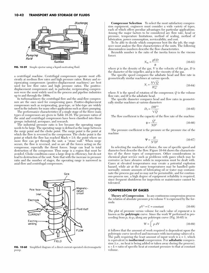
a centrifugal machine. Centrifugal compressors operate most effi-ciently at medium flow rates and high pressure ratios. Rotary and re-ciprocating compressors (positive-displacement machines) are bestused for low flow rates and high pressure ratios. The positive-displacement compressors and, in particular, reciprocating compres-sors were the most widely used in the process and pipeline industriesup to and through the 1960s.
In turbomachinery the centrifugal flow and the axial-flow compres-sors are the ones used for compressing gases. Positive-displacementcompressors such as reciprocating, gear-type, or lobe-type are widelyused in the industry for many other applications such as slurry pumping.
The performance characteristics of a single stage of the three maintypes of compressors are given in Table 10-16. The pressure ratios ofthe axial and centrifugal compressors have been classified into threegroups: industrial, aerospace, and research.
The industrial pressure ratio is low because the operating rangeneeds to be large. The operating range is defined as the range betweenthe surge point and the choke point. The surge point is the point atwhich the flow is reversed in the compressor. The choke point is thepoint at which the flow has reached Mach = 1.0, the point where nomore flow can get through the unit, a “stone wall.” When surgeoccurs, the flow is reversed, and so are all the forces acting on thecompressor, especially the thrust forces. Surge can lead to totaldestruction of the compressor. Thus surge is a region that must beavoided. Choke conditions cause a large drop in efficiency, but do notlead to destruction of the unit. Note that with the increase in pressureratio and the number of stages, the operating range is narrowed inaxial-flow and centrifugal compressors.
Compressor Selection To select the most satisfactory compres-sion equipment, engineers must consider a wide variety of types,each of which offers peculiar advantages for particular applications.Among the major factors to be considered are flow rate, head orpressure, temperature limitations, method of sealing, method oflubrication, power consumption, serviceability, and cost.
To be able to decide which compressor best fits the job, the engi-neer must analyze the flow characteristics of the units. The followingdimensionless numbers describe the flow characteristics.
Reynolds number is the ratio of the inertia forces to the viscousforces
NRe = (10-63)
where ρ is the density of the gas, V is the velocity of the gas, D isthe diameter of the impeller, and µ is the viscosity of the gas.
The specific speed compares the adiabatic head and flow rate ingeometrically similar machines at various speeds.
Ns = (10-64)
where N is the speed of rotation of the compressor, Q is the volumeflow rate, and H is the adiabatic head.
The specific diameter compares head and flow rates in geometri-cally similar machines at various diameters
DS = (10-65)
The flow coefficient is the capacity of the flow rate of the machine
φ = (10-66)
The pressure coefficient is the pressure or the pressure rise of themachine
Ψ = (10-67)
In selecting the machines of choice, the use of specific speed anddiameter best describe the flow. Figure 10-64 shows the characteris-tics of the three types of compressors. Other considerations inchemical plant service such as problems with gases which may becorrosive or have abrasive solids in suspension must be dealt with.Gases at elevated temperatures may create a potential explosionhazard, while air at the same temperatures may be handled quitenormally; minute amounts of lubricating oil or water may contami-nate the process gas and so may not be permissible, and for continu-ous-process use, a high degree of equipment reliability is required,since frequent shutdowns for inspection or maintenance cannot betolerated.
COMPRESSION OF GASES
Theory of Compression In any continuous compression processthe relation of absolute pressure p to volume V is expressed by the for-mula
pVn = C = constant (10-68)The plot of pressure versus volume for each value of exponent n isknown as the polytropic curve. Since the work W performed in pro-ceeding from p1 to p2 along any polytropic curve (Fig. 10-65) is
W = 2
1p dV (10-69)
it follows that the amount of work required is dependent upon thepolytropic curve involved and increases with increasing values of n.The path requiring the least amount of input work is n = 1, whichis equivalent to isothermal compression. For adiabatic compres-sion (i.e., no heat is being added or taken away during the process),n = k = ratio of specific heat at constant pressure to that at constantvolume.
HN 2D2
Q1
ND3
DH1/4
Q
NQ
Had3/4
ρVD
µ
10-42 TRANSPORT AND STORAGE OF FLUIDS
FIG. 10-59 Simple ejector using a liquid-motivating fluid.
FIG. 10-60 Simplified diagram of a direct-current-operated electromagneticpump.
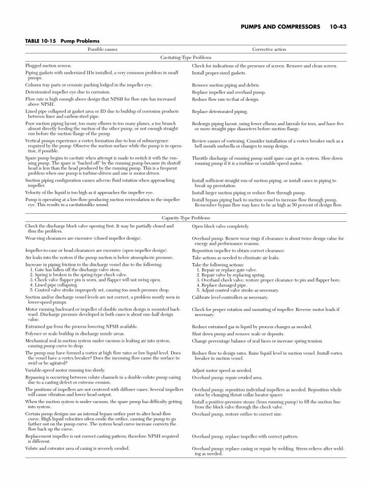
PUMPS AND COMPRESSORS 10-43
TABLE 10-15 Pump Problems
Possible causes Corrective action
Cavitating-Type Problems
Plugged suction screen.Piping gaskets with undersized IDs installed, a very common problem in small
pumps.Column tray parts or ceramic packing lodged in the impeller eye.Deteriorated impeller eye due to corrosion.Flow rate is high enough above design that NPSH for flow rate has increased
above NPSH.Lined pipe collapsed at gasket area or ID due to buildup of corrosion products
between liner and carbon-steel pipe.Poor suction piping layout, too many elbows in too many planes, a tee branch
almost directly feeding the suction of the other pump, or not enough straight run before the suction flange of the pump.
Vertical pumps experience a vortex formation due to loss of submergencerequired by the pump. Observe the suction surface while the pump is in opera-tion, if possible.
Spare pump begins to cavitate when attempt is made to switch it with the run-ning pump. The spare is “backed off” by the running pump because its shutoffhead is less than the head produced by the running pump. This is a frequentproblem when one pump is turbine-driven and one is motor-driven.
Suction piping configuration causes adverse fluid rotation when approachingimpeller.
Velocity of the liquid is too high as it approaches the impeller eye.Pump is operating at a low-flow-producing suction recirculation in the impeller
eye. This results in a cavitationlike sound.
Capacity-Type Problems
Check the discharge block valve opening first. It may be partially closed and thus the problem.
Wear-ring clearances are excessive (closed impeller design).
Impeller-to-case or head clearances are excessive (open impeller design).Air leaks into the system if the pump suction is below atmospheric pressure.Increase in piping friction to the discharge vessel due to the following:
1. Gate has fallen off the discharge valve stem.2. Spring is broken in the spring-type check valve.3. Check valve flapper pin is worn, and flapper will not swing open.4. Lined pipe collapsing.5. Control valve stroke improperly set, causing too much pressure drop.
Suction and/or discharge vessel levels are not correct, a problem mostly seen inlower-speed pumps.
Motor running backward or impeller of double suction design is mounted back-ward. Discharge pressure developed in both cases is about one-half designvalue.
Entrained gas from the process lowering NPSH available.Polymer or scale buildup in discharge nozzle areas.Mechanical seal in suction system under vacuum is leaking air into system,
causing pump curve to drop.The pump may have formed a vortex at high flow rates or low liquid level. Does
the vessel have a vortex breaker? Does the incoming flow cause the surface toswirl or be agitated?
Variable-speed motor running too slowly.Bypassing is occurring between volute channels in a double-volute pump casing
due to a casting defect or extreme erosion.The positions of impellers are not centered with diffuser vanes. Several impellers
will cause vibration and lower head output.When the suction system is under vacuum, the spare pump has difficulty getting
into system.Certain pump designs use an internal bypass orifice port to alter head-flow
curve. High liquid velocities often erode the orifice, causing the pump to gofarther out on the pump curve. The system head curve increase corrects theflow back up the curve.
Replacement impeller is not correct casting pattern; therefore NPSH required is different.
Volute and cutwater area of casing is severely eroded.
Check for indications of the presence of screen. Remove and clean screen.Install proper-sized gaskets.
Remove suction piping and debris.Replace impeller and overhaul pump.Reduce flow rate to that of design.
Replace deteriorated piping.
Redesign piping layout, using fewer elbows and laterals for tees, and have fiveor more straight pipe diameters before suction flange.
Review causes of vortexing. Consider installation of a vortex breaker such as abell mouth umbrella or changes to sump design.
Throttle discharge of running pump until spare can get in system. Slow downrunning pump if it is a turbine or variable-speed motor.
Install sufficient straight run of suction piping, or install vanes in piping tobreak up prerotation.
Install larger suction piping or reduce flow through pump.Install bypass piping back to suction vessel to increase flow through pump.
Remember bypass flow may have to be as high as 50 percent of design flow.
Open block valve completely.
Overhaul pump. Renew wear rings if clearance is about twice design value forenergy and performance reasons.
Reposition impeller to obtain correct clearance.Take actions as needed to eliminate air leaks.Take the following actions:
1. Repair or replace gate valve.2. Repair valve by replacing spring.3. Overhaul check valve; restore proper clearance to pin and flapper bore.4. Replace damaged pipe.5. Adjust control valve stroke as necessary.
Calibrate level controllers as necessary.
Check for proper rotation and mounting of impeller. Reverse motor leads ifnecessary.
Reduce entrained gas in liquid by process changes as needed.Shut down pump and remove scale or deposits.Change percentage balance of seal faces or increase spring tension.
Reduce flow to design rates. Raise liquid level in suction vessel. Install vortexbreaker in suction vessel.
Adjust motor speed as needed.Overhaul pump; repair eroded area.
Overhaul pump; reposition individual impellers as needed. Reposition wholerotor by changing thrust collar locator spacer.
Install a positive-pressure steam (from running pump) to fill the suction linefrom the block valve through the check valve.
Overhaul pump, restore orifice to correct size.
Overhaul pump, replace impeller with correct pattern.
Overhaul pump; replace casing or repair by welding. Stress-relieve after weld-ing as needed.
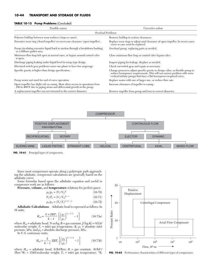
Since most compressors operate along a polytropic path approach-ing the adiabatic, compressor calculations are generally based on theadiabatic curve.
Some formulas based upon the adiabatic equation and useful incompressor work are as follows:
Pressure, volume, and temperature relations for perfect gases:p2 /p1 = (V1/V2)k (10-70)
T2 /T1 = (V1 /V2)k − 1 (10-71)
p2 /p1 = (T2 /T1)k / (k − 1) (10-72)
Adiabatic Calculations Adiabatic head is expressed as follows: InSI units,
Had = (k − 1) / k
− 1 (10-73a)
where Had = adiabatic head, N⋅m/kg; R = gas constant, J/(kg⋅K) = 8314/molecular weight; T1 = inlet gas temperature, K; p1 = absolute inletpressure, kPa; and p2 = absolute discharge pressure, kPa.
In U.S. customary units,
Had = ZRT1 (k − 1) / k
− 1 (10-73b)
where Had = adiabatic head, ft⋅lbf/lbm; R = gas constant, (ft⋅lbf)/(lbm⋅°R) = 1545/molecular weight; T1 = inlet gas temperature, °R;
p2p1
kk − 1
p2p1
k × ZRT1
k − 1
10-44 TRANSPORT AND STORAGE OF FLUIDS
TABLE 10-15 Pump Problems (Concluded )
Possible causes Corrective action
Overload Problems
Polymer buildup between wear surfaces (rings or vanes).Excessive wear ring (closed impeller) or cover-case clearance (open impeller).
Pump circulating excessive liquid back to suction through a breakdown bushingor a diffuser gasket area.
Minimum-flow loop left open at normal rates, or bypass around control valve is open.
Discharge piping leaking under liquid level in sump-type design.Electrical switch gear problems cause one phase to have low amperage.Specific gravity is higher than design specification.
Pump motor not sized for end of curve operation.Open impeller has slight rub on casing. Most often occurs in operations from
250 to 400°F due to piping strain and differential growth in the pump.A replacement impeller was not trimmed to the correct diameter.
Remove buildup to restore clearances.Replace wear rings or adjust axial clearance of open impeller. In severe cases,
cover or case must be replaced.Overhaul pump, replacing parts as needed.
Close minimum-flow loop or control valve bypass valve.
Inspect piping for leakage. Replace as needed.Check out switch gear and repair as necessary.Change process to adjust specific gravity to design value, or throttle pump to
reduce horsepower requirements. This will not correct problem with somevertical turbine pumps that have a flat horsepower-required curve.
Replace motor with one of larger size, or reduce flow rate.Increase clearance of impeller to casing.
Remove impeller from pump and turn to correct diameter.
RECIPROCATING
SLIDING VANE LIQUID PISTON STRAIGHT LOBE HELICAL
ROTARY
POSITIVE DISPLACEMENTIntermittent Flow
EJECTOR
CENTRIFUGAL AXIAL MIXED FLOW
DYNAMIC
CONTINUOUS FLOW
COMPRESSOR
FIG. 10-61 Principal types of compressors.
Axial Flow Compressor
PositiveDisplacement
Centrifugal Compressor
Flow, ft3/m
20
10
30
10510 103 104 1061
Pre
ssur
e R
atio
FIG. 10-62 Performance characteristics of different types of compressors.
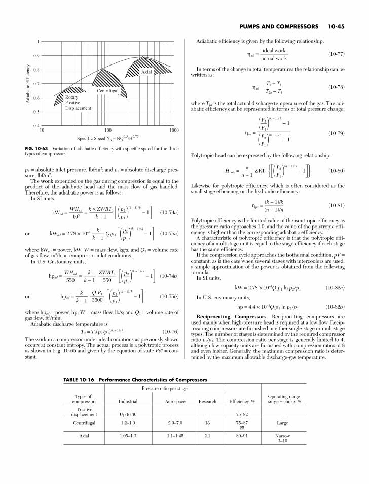
PUMPS AND COMPRESSORS 10-45
0.4
0.5
0.6
0.7
0.8
0.9
1
10 100 1000
Rotary Positive Displacement
Centrifugal
Axial
Specific Speed Ns = NQ0.5/H0.75
Adi
abat
ic E
ffic
ienc
y
FIG. 10-63 Variation of adiabatic efficiency with specific speed for the threetypes of compressors.
TABLE 10-16 Performance Characteristics of Compressors
Pressure ratio per stage
Types of Operating rangecompressors Industrial Aerospace Research Efficiency, % surge − choke, %
Positivedisplacement Up to 30 — — 75–82 —
Centrifugal 1.2–1.9 2.0–7.0 13 75–87 Large25
Axial 1.05–1.3 1.1–1.45 2.1 80–91 Narrow3–10
p1 = absolute inlet pressure, lbf/in2; and p2 = absolute discharge pres-sure, lbf/in2.
The work expended on the gas during compression is equal to theproduct of the adiabatic head and the mass flow of gas handled.Therefore, the adiabatic power is as follows:
In SI units,
kWad = = (k − 1) / k
− 1 (10-74a)
or kWad = 2.78 × 10⁻⁴ Q1p1 (k − 1) / k
− 1 (10-75a)
where kWad = power, kW; W = mass flow, kg/s; and Q1 = volume rateof gas flow, m3/h, at compressor inlet conditions.
In U.S. Customary units,
hpad = = (k − 1) / k
− 1 (10-74b)
or hpad = (k − 1) / k
− 1 (10-75b)
where hpad = power, hp; W = mass flow, lb/s; and Q1 = volume rate ofgas flow, ft3/min.
Adiabatic discharge temperature isT2 = T1(p2 /p1)(k − 1) / k (10-76)
The work in a compressor under ideal conditions as previously shownoccurs at constant entropy. The actual process is a polytropic processas shown in Fig. 10-65 and given by the equation of state Pvn = con-stant.
p2p1
Q1P13600
kk − 1
p2p1
ZWRT1
550k
k − 1
WHad
550
p2p1
kk − 1
p2p1
k × ZWRT1
k − 1WHad
103
Adiabatic efficiency is given by the following relationship:
ηad = (10-77)
In terms of the change in total temperatures the relationship can bewritten as:
ηad = (10-78)
where T2a is the total actual discharge temperature of the gas. The adi-abatic efficiency can be represented in terms of total pressure change:
ηad = (10-79)
Polytropic head can be expressed by the following relationship:
Hpoly = ZRT1 (n − 1 )/ n
− 1 (10-80)
Likewise for polytropic efficiency, which is often considered as thesmall stage efficiency, or the hydraulic efficiency:
ηpc = (10-81)
Polytropic efficiency is the limited value of the isentropic efficiency asthe pressure ratio approaches 1.0, and the value of the polytropic effi-ciency is higher than the corresponding adiabatic efficiency.
A characteristic of polytropic efficiency is that the polytropic effi-ciency of a multistage unit is equal to the stage efficiency if each stagehas the same efficiency.
If the compression cycle approaches the isothermal condition, pV =constant, as is the case when several stages with intercoolers are used,a simple approximation of the power is obtained from the followingformula:
In SI units,
kW = 2.78 × 10⁻⁴Q1p1 ln p2 /p1 (10-82a)
In U.S. customary units,
hp = 4.4 × 10⁻³Q1p1 ln p2 /p1 (10-82b)
Reciprocating Compressors Reciprocating compressors areused mainly when high-pressure head is required at a low flow. Recip-rocating compressors are furnished in either single-stage or multistagetypes. The number of stages is determined by the required compressorratio p2/p1. The compression ratio per stage is generally limited to 4,although low-capacity units are furnished with compression ratios of 8and even higher. Generally, the maximum compression ratio is deter-mined by the maximum allowable discharge-gas temperature.
(k − 1)/k(n − 1)/n
P2P1
nn − 1
PP
2
1
(k − 1 )/ k
− 1
PP
2
1
(n − 1 )/ n
− 1
T2 − T1T2a − T1
ideal workactual work
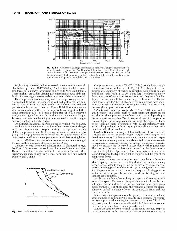
Single-acting air-cooled and water-cooled air compressors are avail-able in sizes up to about 75 kW (100 hp). Such units are available in one,two, three, or four stages for pressure as high as 24 MPa (3500 lbf/in2).These machines are seldom used for gas compression because of the dif-ficulty of preventing gas leakage and contamination of the lubricating oil.
The compressors most commonly used for compressing gases havea crosshead to which the connecting rod and piston rod are con-nected. This provides a straight-line motion for the piston rod andpermits simple packing to be used. Figure 10-66 illustrates a simplesingle-stage machine of this type having a double-acting piston. Eithersingle-acting (Fig. 10-67) or double-acting pistons (Fig. 10-68) may beused, depending on the size of the machine and the number of stages.In some machines double-acting pistons are used in the first stagesand single-acting in the later stages.
On multistage machines, intercoolers are provided between stages.These heat exchangers remove the heat of compression from the gasand reduce its temperature to approximately the temperature existingat the compressor intake. Such cooling reduces the volume of gasgoing to the high-pressure cylinders, reduces the power required forcompression, and keeps the temperature within safe operating limits.
Figure 10-69 illustrates a two-stage compressor end such as mightbe used on the compressor illustrated in Fig. 10-66.
Compressors with horizontal cylinders such as illustrated in Figs.10-66 to 10-68 are most commonly used because of their accessibility.However, machines are also built with vertical cylinders and otherarrangements such as right-angle (one horizontal and one verticalcylinder) and V-angle.
Compressors up to around 75 kW (100 hp) usually have a singlecenter-throw crank, as illustrated in Fig. 10-66. In larger sizes com-pressors are commonly of duplex construction with cranks on eachend of the shaft (see Fig. 10-70). Some large synchronous motor-driven units are of four-corner construction; i.e., they are of double-duplex construction with two connecting rods from each of the twocrank throws (see Fig. 10-71). Steam-driven compressors have one ormore steam cylinders connected directly by piston rod or tie rods tothe gas-cylinder piston or crosshead.
Valve Losses Above piston speeds of 2.5 m/s (500 ft/min), suctionand discharge valve losses begin to exert significant effects on theactual internal compression ratio of most compressors, depending onthe valve port area available. The obvious results are high temperaturerise and higher power requirements than might be expected. Theseeffects become more pronounced with higher-molecular-weightgases. Valve problems can be a very major contributor to down timeexperienced by these machines.
Control Devices In many installations the use of gas is intermit-tent, and some means of controlling the output of the compressor istherefore necessary. In other cases constant output is required despitevariations in discharge pressure, and the control device must operateto maintain a constant compressor speed. Compressor capacity,speed, or pressure may be varied in accordance with requirements.The nature of the control device will depend on the function to beregulated. Regulation of pressure, volume, temperature, or some otherfactor determines the type of regulation required and the type of thecompressor driver.
The most common control requirement is regulation of capacity.Many capacity controls, or unloading devices, as they are usuallytermed, are actuated by the pressure on the discharge side of the com-pressor. A falling pressure indicates that gas is being used faster thanit is being compressed and that more gas is required. A rising pressureindicates that more gas is being compressed than is being used andthat less gas is required.
An obvious method of controlling the capacity of a compressor isto vary the speed. This method is applicable to units driven by vari-able-speed drivers such as steam pistons, steam turbines, gas engines,diesel engines, etc. In these cases the regulator actuates the steam-admission or fuel-admission valve on the compressor driver and thuscontrols the speed.
Motor-driven compressors usually operate at constant speed, andother methods of controlling the capacity are necessary. On recipro-cating compressors discharging into receivers, up to about 75 kW (100hp), two types of control are usually available. These are automatic-start-and-stop control and constant-speed control.
Automatic-start-and-stop control, as its name implies, stops orstarts the compressor by means of a pressure-actuated switch as the
10-46 TRANSPORT AND STORAGE OF FLUIDS
FIG. 10-64 Compressor coverage chart based on the normal range of operation of com-mercially available types shown. Solid lines: use left ordinate, head. Broken lines: use rightordinate, pressure. To convert cubic feet per minute to cubic meters per hour, multiply by1.699; to convert feet to meters, multiply by 0.3048; and to convert pounds-force persquare inch to kilopascals, multiply by 6.895; (°F − 32)5⁄9 = °C.
Fig. 10-65 Polytropic compression curves.
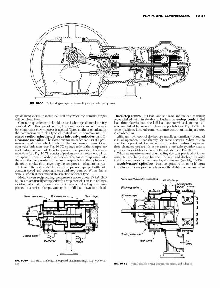
gas demand varies. It should be used only when the demand for gaswill be intermittent.
Constant-speed control should be used when gas demand is fairlyconstant. With this type of control, the compressor runs continuouslybut compresses only when gas is needed. Three methods of unloadingthe compressor with this type of control are in common use: (1)closed suction unloaders, (2) open inlet-valve unloaders, and (3)clearance unloaders. The closed suction unloader consists of a pres-sure-actuated valve which shuts off the compressor intake. Openinlet-valve unloaders (see Fig. 10-72) operate to hold the compressorinlet valves open and thereby prevent compression. Clearanceunloaders (see Fig. 10-73) consist of pockets or small reservoirs whichare opened when unloading is desired. The gas is compressed intothem on the compression stroke and reexpands into the cylinder onthe return stroke, thus preventing the compression of additional gas.
It is sometimes desirable to have a compressor equipped with bothconstant-speed and automatic-start-and-stop control. When this isdone, a switch allows immediate selection of either type.
Motor-driven reciprocating compressors above about 75 kW (100hp) in size are usually equipped with a step control. This is in reality avariation of constant-speed control in which unloading is accom-plished in a series of steps, varying from full load down to no load.
Three-step control (full load, one-half load, and no load) is usuallyaccomplished with inlet-valve unloaders. Five-step control (fullload, three-fourths load, one-half load, one-fourth load, and no load)is accomplished by means of clearance pockets (see Fig. 10-74). Onsome machines, inlet-valve and clearance-control unloading are usedin combination.
Although such control devices are usually automatically operated,manual operation is satisfactory for some services. When manualoperation is provided, it often consists of a valve or valves to open andclose clearance pockets. In some cases, a movable cylinder head isprovided for variable clearance in the cylinder (see Fig. 10-75).
When no capacity control or unloading device is provided, it is nec-essary to provide bypasses between the inlet and discharge in orderthat the compressor can be started against no load (see Fig. 10-76).
Nonlubricated Cylinders Most compressors use oil to lubricatethe cylinder. In some processes, however, the slightest oil contamination
PUMPS AND COMPRESSORS 10-47
FIG. 10-66 Typical single-stage, double-acting water-cooled compressor.
FIG. 10-67 Two-stage single-acting opposed piston in a single step-type cylin-der. FIG. 10-68 Typical double-acting compressor piston and cylinder.
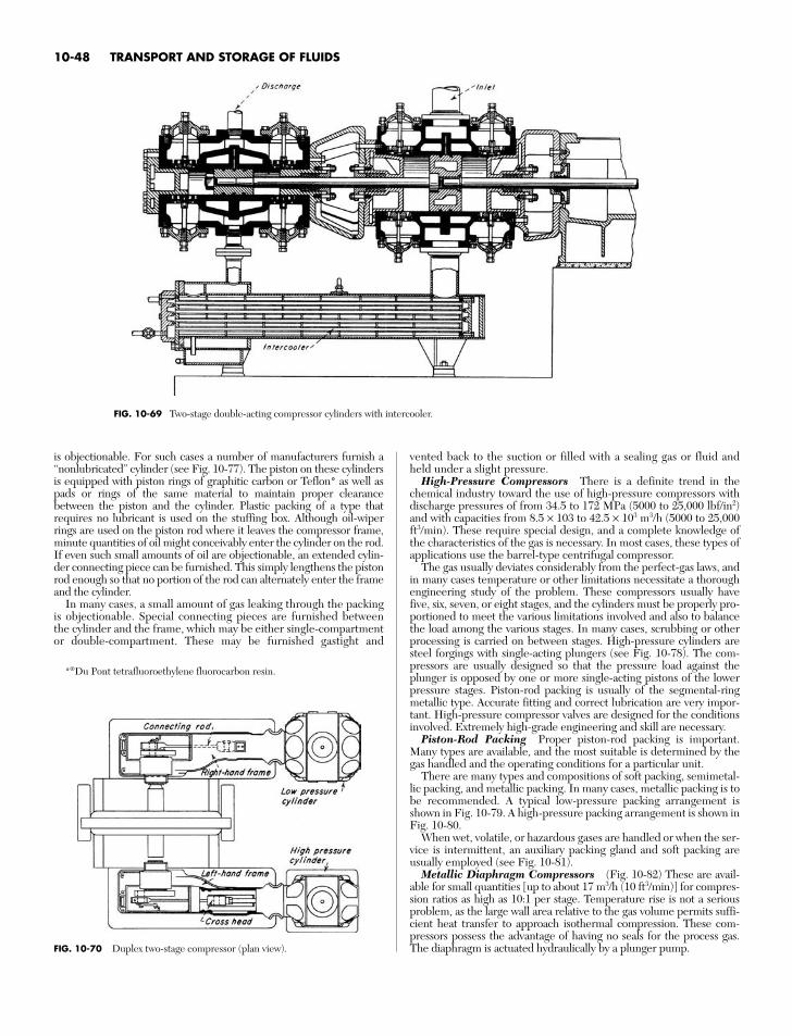
is objectionable. For such cases a number of manufacturers furnish a“nonlubricated” cylinder (see Fig. 10-77). The piston on these cylindersis equipped with piston rings of graphitic carbon or Teflon* as well aspads or rings of the same material to maintain proper clearancebetween the piston and the cylinder. Plastic packing of a type thatrequires no lubricant is used on the stuffing box. Although oil-wiperrings are used on the piston rod where it leaves the compressor frame,minute quantities of oil might conceivably enter the cylinder on the rod.If even such small amounts of oil are objectionable, an extended cylin-der connecting piece can be furnished. This simply lengthens the pistonrod enough so that no portion of the rod can alternately enter the frameand the cylinder.
In many cases, a small amount of gas leaking through the packingis objectionable. Special connecting pieces are furnished betweenthe cylinder and the frame, which may be either single-compartmentor double-compartment. These may be furnished gastight and
vented back to the suction or filled with a sealing gas or fluid andheld under a slight pressure.
High-Pressure Compressors There is a definite trend in thechemical industry toward the use of high-pressure compressors withdischarge pressures of from 34.5 to 172 MPa (5000 to 25,000 lbf/in2)and with capacities from 8.5 × 10³ to 42.5 × 10³ m3/h (5000 to 25,000ft3/min). These require special design, and a complete knowledge ofthe characteristics of the gas is necessary. In most cases, these types ofapplications use the barrel-type centrifugal compressor.
The gas usually deviates considerably from the perfect-gas laws, andin many cases temperature or other limitations necessitate a thoroughengineering study of the problem. These compressors usually havefive, six, seven, or eight stages, and the cylinders must be properly pro-portioned to meet the various limitations involved and also to balancethe load among the various stages. In many cases, scrubbing or otherprocessing is carried on between stages. High-pressure cylinders aresteel forgings with single-acting plungers (see Fig. 10-78). The com-pressors are usually designed so that the pressure load against theplunger is opposed by one or more single-acting pistons of the lowerpressure stages. Piston-rod packing is usually of the segmental-ringmetallic type. Accurate fitting and correct lubrication are very impor-tant. High-pressure compressor valves are designed for the conditionsinvolved. Extremely high-grade engineering and skill are necessary.
Piston-Rod Packing Proper piston-rod packing is important.Many types are available, and the most suitable is determined by thegas handled and the operating conditions for a particular unit.
There are many types and compositions of soft packing, semimetal-lic packing, and metallic packing. In many cases, metallic packing is tobe recommended. A typical low-pressure packing arrangement isshown in Fig. 10-79. A high-pressure packing arrangement is shown inFig. 10-80.
When wet, volatile, or hazardous gases are handled or when the ser-vice is intermittent, an auxiliary packing gland and soft packing areusually employed (see Fig. 10-81).
Metallic Diaphragm Compressors (Fig. 10-82) These are avail-able for small quantities [up to about 17 m3/h (10 ft3/min)] for compres-sion ratios as high as 10:1 per stage. Temperature rise is not a seriousproblem, as the large wall area relative to the gas volume permits suffi-cient heat transfer to approach isothermal compression. These com-pressors possess the advantage of having no seals for the process gas.The diaphragm is actuated hydraulically by a plunger pump.
10-48 TRANSPORT AND STORAGE OF FLUIDS
*®Du Pont tetrafluoroethylene fluorocarbon resin.
FIG. 10-69 Two-stage double-acting compressor cylinders with intercooler.
FIG. 10-70 Duplex two-stage compressor (plan view).
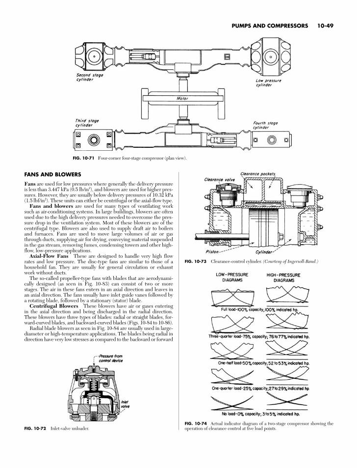
FANS AND BLOWERS
Fans are used for low pressures where generally the delivery pressureis less than 3.447 kPa (0.5 lb/in2), and blowers are used for higher pres-sures. However, they are usually below delivery pressures of 10.32 kPa(1.5 lbf/in2). These units can either be centrifugal or the axial-flow type.
Fans and blowers are used for many types of ventilating worksuch as air-conditioning systems. In large buildings, blowers are oftenused due to the high delivery pressures needed to overcome the pres-sure drop in the ventilation system. Most of these blowers are of thecentrifugal type. Blowers are also used to supply draft air to boilersand furnaces. Fans are used to move large volumes of air or gasthrough ducts, supplying air for drying, conveying material suspendedin the gas stream, removing fumes, condensing towers and other high-flow, low-pressure applications.
Axial-Flow Fans These are designed to handle very high flowrates and low pressure. The disc-type fans are similar to those of ahousehold fan. They are usually for general circulation or exhaustwork without ducts.
The so-called propeller-type fans with blades that are aerodynami-cally designed (as seen in Fig. 10-83) can consist of two or morestages. The air in these fans enters in an axial direction and leaves inan axial direction. The fans usually have inlet guide vanes followed bya rotating blade, followed by a stationary (stator) blade.
Centrifugal Blowers These blowers have air or gases enteringin the axial direction and being discharged in the radial direction.These blowers have three types of blades: radial or straight blades, for-ward-curved blades, and backward-curved blades (Figs. 10-84 to 10-86).
Radial blade blowers as seen in Fig. 10-84 are usually used in large-diameter or high-temperature applications. The blades being radial indirection have very low stresses as compared to the backward or forward
PUMPS AND COMPRESSORS 10-49
FIG. 10-71 Four-corner four-stage compressor (plan view).
FIG. 10-72 Inlet-valve unloader.
FIG. 10-73 Clearance-control cylinder. (Courtesy of Ingersoll-Rand.)
FIG. 10-74 Actual indicator diagram of a two-stage compressor showing theoperation of clearance control at five load points.
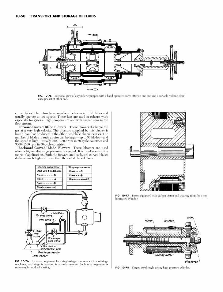
curve blades. The rotors have anywhere between 4 to 12 blades andusually operate at low speeds. These fans are used in exhaust workespecially for gases at high temperature and with suspensions in theflow stream.
Forward-Curved Blade Blowers These blowers discharge thegas at a very high velocity. The pressure supplied by this blower islower than that produced in the other two blade characteristics. Thenumber of blades in such a rotor can be large—up to 50 blades—andthe speed is high—usually 3600–1800 rpm in 60-cycle countries and3000–1500 rpm in 50-cycle countries.
Backward-Curved Blade Blowers These blowers are usedwhen a higher discharge pressure is needed. It is used over a widerange of applications. Both the forward and backward curved bladesdo have much higher stresses than the radial bladed blower.
10-50 TRANSPORT AND STORAGE OF FLUIDS
FIG. 10-75 Sectional view of a cylinder equipped with a hand-operated valve lifter on one end and a variable-volume clear-ance pocket at other end.
FIG. 10-76 Bypass arrangement for a single-stage compressor. On multistagemachines, each stage is bypassed in a similar manner. Such an arrangement isnecessary for no-load starting.
FIG. 10-77 Piston equipped with carbon piston and wearing rings for a non-lubricated cylinder.
FIG. 10-78 Forged-steel single-acting high-pressure cylinder.
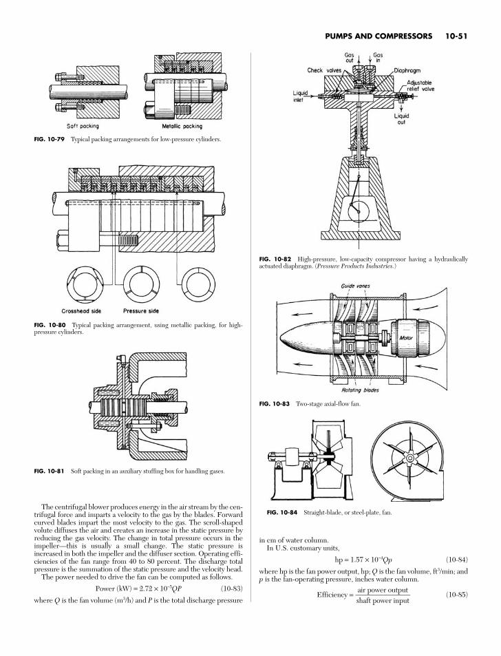
PUMPS AND COMPRESSORS 10-51
FIG. 10-79 Typical packing arrangements for low-pressure cylinders.
FIG. 10-80 Typical packing arrangement, using metallic packing, for high-pressure cylinders.
FIG. 10-81 Soft packing in an auxiliary stuffing box for handling gases.
FIG. 10-82 High-pressure, low-capacity compressor having a hydraulicallyactuated diaphragm. (Pressure Products Industries.)
FIG. 10-84 Straight-blade, or steel-plate, fan.The centrifugal blower produces energy in the air stream by the cen-
trifugal force and imparts a velocity to the gas by the blades. Forwardcurved blades impart the most velocity to the gas. The scroll-shapedvolute diffuses the air and creates an increase in the static pressure byreducing the gas velocity. The change in total pressure occurs in theimpeller—this is usually a small change. The static pressure isincreased in both the impeller and the diffuser section. Operating effi-ciencies of the fan range from 40 to 80 percent. The discharge totalpressure is the summation of the static pressure and the velocity head.
The power needed to drive the fan can be computed as follows.
Power (kW) = 2.72 × 10⁻⁵QP (10-83)
where Q is the fan volume (m3/h) and P is the total discharge pressure
in cm of water column.In U.S. customary units,
hp = 1.57 × 10⁻⁴Qp (10-84)
where hp is the fan power output, hp; Q is the fan volume, ft3/min; andp is the fan-operating pressure, inches water column.
Efficiency = (10-85)air power outputshaft power input
FIG. 10-83 Two-stage axial-flow fan.
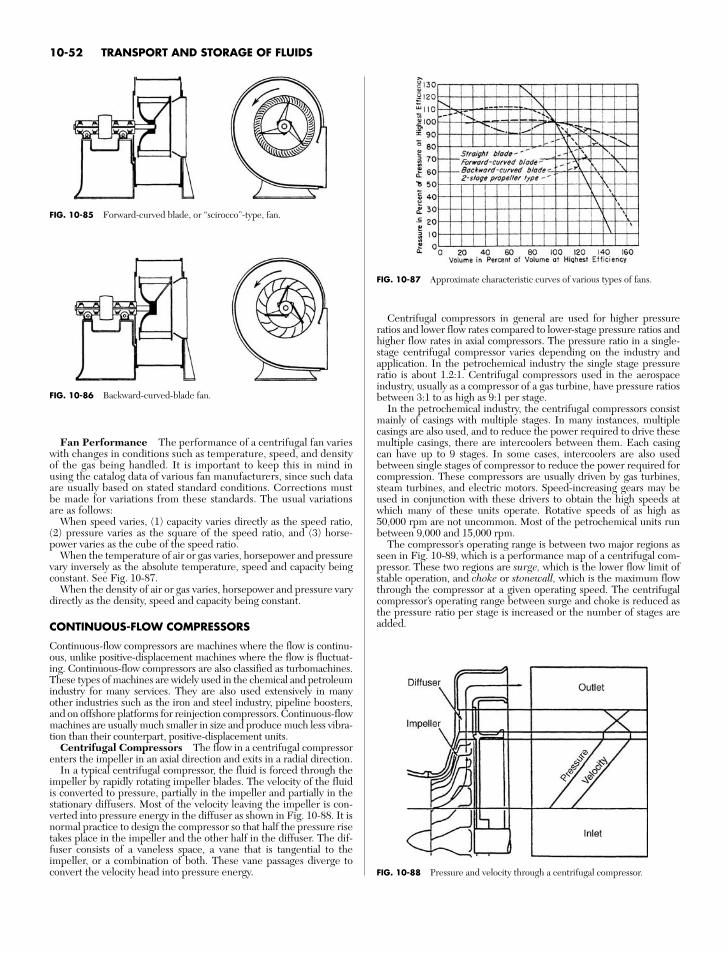
Fan Performance The performance of a centrifugal fan varieswith changes in conditions such as temperature, speed, and densityof the gas being handled. It is important to keep this in mind inusing the catalog data of various fan manufacturers, since such dataare usually based on stated standard conditions. Corrections mustbe made for variations from these standards. The usual variationsare as follows:
When speed varies, (1) capacity varies directly as the speed ratio,(2) pressure varies as the square of the speed ratio, and (3) horse-power varies as the cube of the speed ratio.
When the temperature of air or gas varies, horsepower and pressurevary inversely as the absolute temperature, speed and capacity beingconstant. See Fig. 10-87.
When the density of air or gas varies, horsepower and pressure varydirectly as the density, speed and capacity being constant.
CONTINUOUS-FLOW COMPRESSORS
Continuous-flow compressors are machines where the flow is continu-ous, unlike positive-displacement machines where the flow is fluctuat-ing. Continuous-flow compressors are also classified as turbomachines.These types of machines are widely used in the chemical and petroleumindustry for many services. They are also used extensively in manyother industries such as the iron and steel industry, pipeline boosters,and on offshore platforms for reinjection compressors. Continuous-flowmachines are usually much smaller in size and produce much less vibra-tion than their counterpart, positive-displacement units.
Centrifugal Compressors The flow in a centrifugal compressorenters the impeller in an axial direction and exits in a radial direction.
In a typical centrifugal compressor, the fluid is forced through theimpeller by rapidly rotating impeller blades. The velocity of the fluidis converted to pressure, partially in the impeller and partially in thestationary diffusers. Most of the velocity leaving the impeller is con-verted into pressure energy in the diffuser as shown in Fig. 10-88. It isnormal practice to design the compressor so that half the pressure risetakes place in the impeller and the other half in the diffuser. The dif-fuser consists of a vaneless space, a vane that is tangential to theimpeller, or a combination of both. These vane passages diverge toconvert the velocity head into pressure energy.
10-52 TRANSPORT AND STORAGE OF FLUIDS
FIG. 10-86 Backward-curved-blade fan.
FIG. 10-87 Approximate characteristic curves of various types of fans.
FIG. 10-88 Pressure and velocity through a centrifugal compressor.
Centrifugal compressors in general are used for higher pressureratios and lower flow rates compared to lower-stage pressure ratios andhigher flow rates in axial compressors. The pressure ratio in a single-stage centrifugal compressor varies depending on the industry andapplication. In the petrochemical industry the single stage pressureratio is about 1.2:1. Centrifugal compressors used in the aerospaceindustry, usually as a compressor of a gas turbine, have pressure ratiosbetween 3:1 to as high as 9:1 per stage.
In the petrochemical industry, the centrifugal compressors consistmainly of casings with multiple stages. In many instances, multiplecasings are also used, and to reduce the power required to drive thesemultiple casings, there are intercoolers between them. Each casingcan have up to 9 stages. In some cases, intercoolers are also usedbetween single stages of compressor to reduce the power required forcompression. These compressors are usually driven by gas turbines,steam turbines, and electric motors. Speed-increasing gears may beused in conjunction with these drivers to obtain the high speeds atwhich many of these units operate. Rotative speeds of as high as50,000 rpm are not uncommon. Most of the petrochemical units runbetween 9,000 and 15,000 rpm.
The compressor’s operating range is between two major regions asseen in Fig. 10-89, which is a performance map of a centrifugal com-pressor. These two regions are surge, which is the lower flow limit ofstable operation, and choke or stonewall, which is the maximum flowthrough the compressor at a given operating speed. The centrifugalcompressor’s operating range between surge and choke is reduced asthe pressure ratio per stage is increased or the number of stages areadded.
FIG. 10-85 Forward-curved blade, or “scirocco”-type, fan.
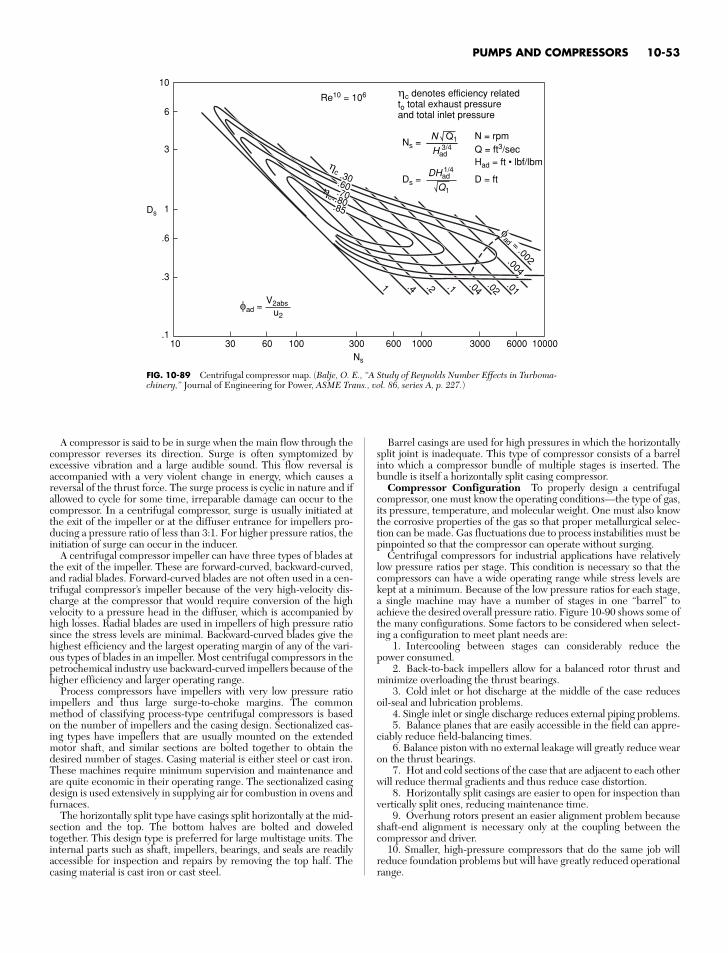
PUMPS AND COMPRESSORS 10-53
.60.60
.3
.6
1
3
6
10
Ds
Ns
Ns =N = rpmQ = ft3/secHad = ft • lbf/lbm
Ds = D = ft
ηc denotes efficiency relatedto total exhaust pressureand total inlet pressure
.13010 60 100 300
1 .4 .2 .1 .04.02
.01
600 1000 3000 6000 10000
.004
.30.70.70.80.80.85.85
.70.80.85
Re10 = 106
N Q1
Had
DHad
Q1
ηc 1/4
ηc
ηc
φad =V2abs
u2
3/4
.60.60.60
φad = .002
FIG. 10-89 Centrifugal compressor map. (Balje, O. E., “A Study of Reynolds Number Effects in Turboma-chinery,” Journal of Engineering for Power, ASME Trans., vol. 86, series A, p. 227.)
A compressor is said to be in surge when the main flow through thecompressor reverses its direction. Surge is often symptomized byexcessive vibration and a large audible sound. This flow reversal isaccompanied with a very violent change in energy, which causes areversal of the thrust force. The surge process is cyclic in nature and ifallowed to cycle for some time, irreparable damage can occur to thecompressor. In a centrifugal compressor, surge is usually initiated atthe exit of the impeller or at the diffuser entrance for impellers pro-ducing a pressure ratio of less than 3:1. For higher pressure ratios, theinitiation of surge can occur in the inducer.
A centrifugal compressor impeller can have three types of blades atthe exit of the impeller. These are forward-curved, backward-curved,and radial blades. Forward-curved blades are not often used in a cen-trifugal compressor’s impeller because of the very high-velocity dis-charge at the compressor that would require conversion of the highvelocity to a pressure head in the diffuser, which is accompanied byhigh losses. Radial blades are used in impellers of high pressure ratiosince the stress levels are minimal. Backward-curved blades give thehighest efficiency and the largest operating margin of any of the vari-ous types of blades in an impeller. Most centrifugal compressors in thepetrochemical industry use backward-curved impellers because of thehigher efficiency and larger operating range.
Process compressors have impellers with very low pressure ratioimpellers and thus large surge-to-choke margins. The commonmethod of classifying process-type centrifugal compressors is basedon the number of impellers and the casing design. Sectionalized cas-ing types have impellers that are usually mounted on the extendedmotor shaft, and similar sections are bolted together to obtain thedesired number of stages. Casing material is either steel or cast iron.These machines require minimum supervision and maintenance andare quite economic in their operating range. The sectionalized casingdesign is used extensively in supplying air for combustion in ovens andfurnaces.
The horizontally split type have casings split horizontally at the mid-section and the top. The bottom halves are bolted and doweledtogether. This design type is preferred for large multistage units. Theinternal parts such as shaft, impellers, bearings, and seals are readilyaccessible for inspection and repairs by removing the top half. Thecasing material is cast iron or cast steel.
Barrel casings are used for high pressures in which the horizontallysplit joint is inadequate. This type of compressor consists of a barrelinto which a compressor bundle of multiple stages is inserted. Thebundle is itself a horizontally split casing compressor.
Compressor Configuration To properly design a centrifugalcompressor, one must know the operating conditions—the type of gas,its pressure, temperature, and molecular weight. One must also knowthe corrosive properties of the gas so that proper metallurgical selec-tion can be made. Gas fluctuations due to process instabilities must bepinpointed so that the compressor can operate without surging.
Centrifugal compressors for industrial applications have relativelylow pressure ratios per stage. This condition is necessary so that thecompressors can have a wide operating range while stress levels arekept at a minimum. Because of the low pressure ratios for each stage,a single machine may have a number of stages in one “barrel” toachieve the desired overall pressure ratio. Figure 10-90 shows some ofthe many configurations. Some factors to be considered when select-ing a configuration to meet plant needs are:
1. Intercooling between stages can considerably reduce thepower consumed.
2. Back-to-back impellers allow for a balanced rotor thrust andminimize overloading the thrust bearings.
3. Cold inlet or hot discharge at the middle of the case reducesoil-seal and lubrication problems.
4. Single inlet or single discharge reduces external piping problems.5. Balance planes that are easily accessible in the field can appre-
ciably reduce field-balancing times.6. Balance piston with no external leakage will greatly reduce wear
on the thrust bearings.7. Hot and cold sections of the case that are adjacent to each other
will reduce thermal gradients and thus reduce case distortion.8. Horizontally split casings are easier to open for inspection than
vertically split ones, reducing maintenance time.9. Overhung rotors present an easier alignment problem because
shaft-end alignment is necessary only at the coupling between thecompressor and driver.
10. Smaller, high-pressure compressors that do the same job willreduce foundation problems but will have greatly reduced operationalrange.
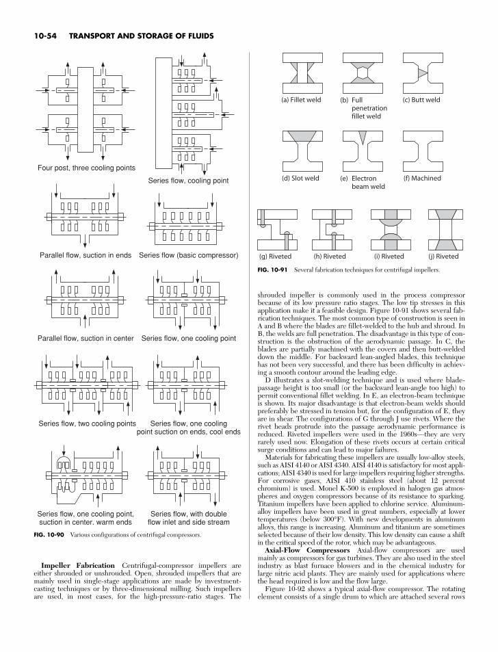
shrouded impeller is commonly used in the process compressorbecause of its low pressure ratio stages. The low tip stresses in thisapplication make it a feasible design. Figure 10-91 shows several fab-rication techniques. The most common type of construction is seen inA and B where the blades are fillet-welded to the hub and shroud. InB, the welds are full penetration. The disadvantage in this type of con-struction is the obstruction of the aerodynamic passage. In C, theblades are partially machined with the covers and then butt-weldeddown the middle. For backward lean-angled blades, this techniquehas not been very successful, and there has been difficulty in achiev-ing a smooth contour around the leading edge.
D illustrates a slot-welding technique and is used where blade-passage height is too small (or the backward lean-angle too high) topermit conventional fillet welding. In E, an electron-beam techniqueis shown. Its major disadvantage is that electron-beam welds shouldpreferably be stressed in tension but, for the configuration of E, theyare in shear. The configurations of G through J use rivets. Where therivet heads protrude into the passage aerodynamic performance isreduced. Riveted impellers were used in the 1960s—they are veryrarely used now. Elongation of these rivets occurs at certain criticalsurge conditions and can lead to major failures.
Materials for fabricating these impellers are usually low-alloy steels,such as AISI 4140 or AISI 4340. AISI 4140 is satisfactory for most appli-cations; AISI 4340 is used for large impellers requiring higher strengths.For corrosive gases, AISI 410 stainless steel (about 12 percentchromium) is used. Monel K-500 is employed in halogen gas atmos-pheres and oxygen compressors because of its resistance to sparking.Titanium impellers have been applied to chlorine service. Aluminum-alloy impellers have been used in great numbers, especially at lowertemperatures (below 300°F). With new developments in aluminumalloys, this range is increasing. Aluminum and titanium are sometimesselected because of their low density. This low density can cause a shiftin the critical speed of the rotor, which may be advantageous.
Axial-Flow Compressors Axial-flow compressors are usedmainly as compressors for gas turbines. They are also used in the steelindustry as blast furnace blowers and in the chemical industry forlarge nitric acid plants. They are mainly used for applications wherethe head required is low and the flow large.
Figure 10-92 shows a typical axial-flow compressor. The rotatingelement consists of a single drum to which are attached several rows
10-54 TRANSPORT AND STORAGE OF FLUIDS
Four post, three cooling points
Parallel flow, suction in ends
Series flow, cooling point
Series flow (basic compressor)
Parallel flow, suction in center Series flow, one cooling point
Series flow, two cooling points Series flow, one coolingpoint suction on ends, cool ends
Series flow, one cooling point,suction in center, warm ends
Series flow, with doubleflow inlet and side stream
FIG. 10-90 Various configurations of centrifugal compressors.
(c) Butt weldFullpenetrationfillet weld
(b)(a) Fillet weld
(f) MachinedElectronbeam weld
(e)(d) Slot weld
(g) Riveted (h) Riveted (i) Riveted (j) Riveted
FIG. 10-91 Several fabrication techniques for centrifugal impellers.
Impeller Fabrication Centrifugal-compressor impellers areeither shrouded or unshrouded. Open, shrouded impellers that aremainly used in single-stage applications are made by investment-casting techniques or by three-dimensional milling. Such impellersare used, in most cases, for the high-pressure-ratio stages. The
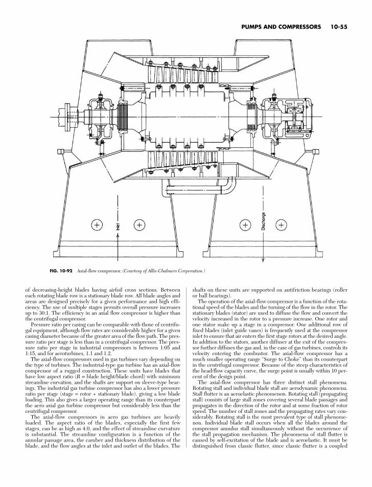
of decreasing-height blades having airfoil cross sections. Betweeneach rotating blade row is a stationary blade row. All blade angles andareas are designed precisely for a given performance and high effi-ciency. The use of multiple stages permits overall pressure increasesup to 30:1. The efficiency in an axial flow compressor is higher thanthe centrifugal compressor.
Pressure ratio per casing can be comparable with those of centrifu-gal equipment, although flow rates are considerably higher for a givencasing diameter because of the greater area of the flow path. The pres-sure ratio per stage is less than in a centrifugal compressor. The pres-sure ratio per stage in industrial compressors is between 1:05 and1:15, and for aeroturbines, 1.1 and 1.2.
The axial-flow compressors used in gas turbines vary depending onthe type of turbines. The industrial-type gas turbine has an axial-flowcompressor of a rugged construction. These units have blades thathave low aspect ratio (R = blade height/blade chord) with minimumstreamline curvation, and the shafts are support on sleeve-type bear-ings. The industrial gas turbine compressor has also a lower pressureratio per stage (stage = rotor + stationary blade), giving a low bladeloading. This also gives a larger operating range than its counterpartthe aero axial gas turbine compressor but considerably less than thecentrifugal compressor.
The axial-flow compressors in aero gas turbines are heavilyloaded. The aspect ratio of the blades, especially the first fewstages, can be as high as 4.0, and the effect of streamline curvatureis substantial. The streamline configuration is a function of theannular passage area, the camber and thickness distribution of theblade, and the flow angles at the inlet and outlet of the blades. The
shafts on these units are supported on antifriction bearings (rolleror ball bearings).
The operation of the axial-flow compressor is a function of the rota-tional speed of the blades and the turning of the flow in the rotor. Thestationary blades (stator) are used to diffuse the flow and convert thevelocity increased in the rotor to a pressure increase. One rotor andone stator make up a stage in a compressor. One additional row offixed blades (inlet guide vanes) is frequently used at the compressorinlet to ensure that air enters the first stage rotors at the desired angle.In addition to the stators, another diffuser at the exit of the compres-sor further diffuses the gas and, in the case of gas turbines, controls itsvelocity entering the combustor. The axial-flow compressor has amuch smaller operating range “Surge to Choke” than its counterpartin the centrifugal compressor. Because of the steep characteristics ofthe head/flow capacity curve, the surge point is usually within 10 per-cent of the design point.
The axial-flow compressor has three distinct stall phenomena.Rotating stall and individual blade stall are aerodynamic phenomena.Stall flutter is an aeroelastic phenomenon. Rotating stall (propagatingstall) consists of large stall zones covering several blade passages andpropagates in the direction of the rotor and at some fraction of rotorspeed. The number of stall zones and the propagating rates vary con-siderably. Rotating stall is the most prevalent type of stall phenome-non. Individual blade stall occurs when all the blades around thecompressor annulus stall simultaneously without the occurrence ofthe stall propagation mechanism. The phenomena of stall flutter iscaused by self-excitation of the blade and is aeroelastic. It must bedistinguished from classic flutter, since classic flutter is a coupled
PUMPS AND COMPRESSORS 10-55
FIG. 10-92 Axial-flow compressor. (Courtesy of Allis-Chalmers Corporation.)
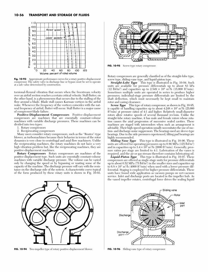
torsional-flexural vibration that occurs when the freestream velocityover an airfoil section reaches a certain critical velocity. Stall flutter, onthe other hand, is a phenomenon that occurs due to the stalling of theflow around a blade. Blade stall causes Karman vortices in the airfoilwake. Whenever the frequency of the vortices coincides with the nat-ural frequency of airfoil, flutter will occur. Stall flutter is a major causeof compressor-blade failure.
Positive-Displacement Compressors Positive-displacementcompressors are machines that are essentially constant-volumemachines with variable discharge pressures. These machines can bedivided into two types:
1. Rotary compressors2. Reciprocating compressorsMany users consider rotary compressors, such as the “Rootes”-type
blower, as turbomachines because their behavior in terms of the rotordynamics is very close to centrifugal and axial flow machinery. Unlikethe reciprocating machines, the rotary machines do not have a veryhigh vibration problem but, like the reciprocating machines, they arepositive-displacement machines.
Rotary Compressors Rotary compressors are machines of thepositive-displacement type. Such units are essentially constant-volumemachines with variable discharge pressure. The volume can be variedonly by changing the speed or by bypassing or wasting some of thecapacity of the machine. The discharge pressure will vary with the resis-tance on the discharge side of the system. A characteristic curve typicalof the form produced by these rotary units is shown in Fig. 10-93.
Rotary compressors are generally classified as of the straight-lobe type,screw type, sliding-vane type, and liquid-piston type.
Straight-Lobe Type This type is illustrated in Fig. 10-94. Suchunits are available for pressure differentials up to about 83 kPa(12 lbf/in2) and capacities up to 2.549 × 10⁴ m3/h (15,000 ft3/min).Sometimes multiple units are operated in series to produce higherpressures; individual-stage pressure differentials are limited by theshaft deflection, which must necessarily be kept small to maintainrotor and casing clearance.
Screw Type This type of rotary compressor, as shown in Fig. 10-95,is capable of handling capacities up to about 4.248 × 10⁴ m3/h (25,000ft3/min) at pressure ratios of 4:1 and higher. Relatively small-diameterrotors allow rotative speeds of several thousand rev/min. Unlike thestraight-lobe rotary machine, it has male and female rotors whose rota-tion causes the axial progression of successive sealed cavities. Thesemachines are staged with intercoolers when such an arrangement isadvisable. Their high-speed operation usually necessitates the use of suc-tion- and discharge-noise suppressors. The bearings used are sleeve-typebearings. Due to the side pressures experienced, tilting pad bearings arehighly recommended.
Sliding-Vane Type This type is illustrated in Fig. 10-96. Theseunits are offered for operating pressures up to 0.86 MPa (125 lbf/in2)and in capacities up to 3.4 × 10³ m3/h (2000 ft3/min). Generally, pres-sure ratios per stage are limited to 4:1. Lubrication of the vanes isrequired, and the air or gas stream therefore contains lubricating oil.
Liquid-Piston Type This type is illustrated in Fig. 10-97. Thesecompressors are offered as single-stage units for pressure differentialsup to about 0.52 MPa (75 lbf/in2) in the smaller sizes and capacities upto 6.8 × 10³ m3/h (4000 ft3/min) when used with a lower pressure dif-ferential. Staging is employed for higher pressure differentials. Theseunits have found wide application as vacuum pumps on wet-vacuumservice. Inlet and discharge ports are located in the impeller hub. Asthe vaned impeller rotates, centrifugal force drives the sealing liquid
10-56 TRANSPORT AND STORAGE OF FLUIDS
FIG. 10-96 Sliding-vane type of rotary compressor.
Fig. 10-93 Approximate performance curves for a rotary positive-displacementcompressor. The safety valve in discharge line or bypass must be set to operateat a safe value determined by construction.
FIG. 10-95 Screw-type rotary compressor.
FIG. 10-94 Two-impeller type of rotary positive-displacement blower.
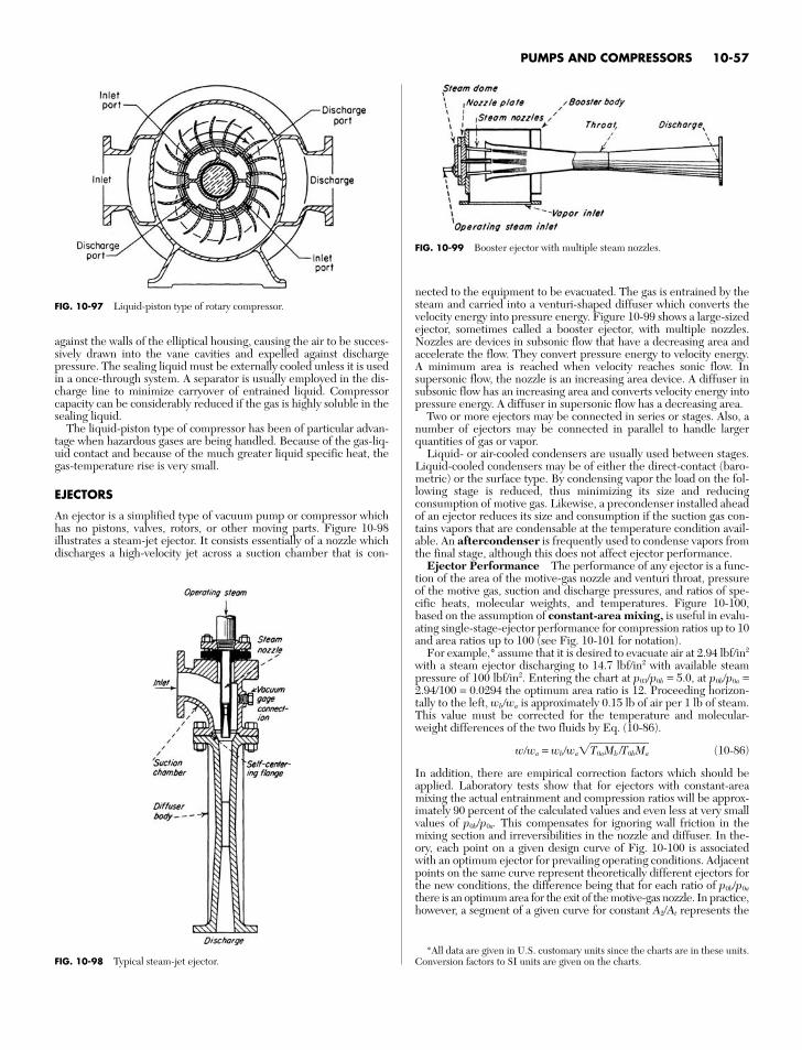
against the walls of the elliptical housing, causing the air to be succes-sively drawn into the vane cavities and expelled against dischargepressure. The sealing liquid must be externally cooled unless it is usedin a once-through system. A separator is usually employed in the dis-charge line to minimize carryover of entrained liquid. Compressorcapacity can be considerably reduced if the gas is highly soluble in thesealing liquid.
The liquid-piston type of compressor has been of particular advan-tage when hazardous gases are being handled. Because of the gas-liq-uid contact and because of the much greater liquid specific heat, thegas-temperature rise is very small.
EJECTORS
An ejector is a simplified type of vacuum pump or compressor whichhas no pistons, valves, rotors, or other moving parts. Figure 10-98illustrates a steam-jet ejector. It consists essentially of a nozzle whichdischarges a high-velocity jet across a suction chamber that is con-
nected to the equipment to be evacuated. The gas is entrained by thesteam and carried into a venturi-shaped diffuser which converts thevelocity energy into pressure energy. Figure 10-99 shows a large-sizedejector, sometimes called a booster ejector, with multiple nozzles.Nozzles are devices in subsonic flow that have a decreasing area andaccelerate the flow. They convert pressure energy to velocity energy.A minimum area is reached when velocity reaches sonic flow. Insupersonic flow, the nozzle is an increasing area device. A diffuser insubsonic flow has an increasing area and converts velocity energy intopressure energy. A diffuser in supersonic flow has a decreasing area.
Two or more ejectors may be connected in series or stages. Also, anumber of ejectors may be connected in parallel to handle largerquantities of gas or vapor.
Liquid- or air-cooled condensers are usually used between stages.Liquid-cooled condensers may be of either the direct-contact (baro-metric) or the surface type. By condensing vapor the load on the fol-lowing stage is reduced, thus minimizing its size and reducingconsumption of motive gas. Likewise, a precondenser installed aheadof an ejector reduces its size and consumption if the suction gas con-tains vapors that are condensable at the temperature condition avail-able. An aftercondenser is frequently used to condense vapors fromthe final stage, although this does not affect ejector performance.
Ejector Performance The performance of any ejector is a func-tion of the area of the motive-gas nozzle and venturi throat, pressureof the motive gas, suction and discharge pressures, and ratios of spe-cific heats, molecular weights, and temperatures. Figure 10-100,based on the assumption of constant-area mixing, is useful in evalu-ating single-stage-ejector performance for compression ratios up to 10and area ratios up to 100 (see Fig. 10-101 for notation).
For example,* assume that it is desired to evacuate air at 2.94 lbf/in2
with a steam ejector discharging to 14.7 lbf/in2 with available steampressure of 100 lbf/in2. Entering the chart at p03/p0b = 5.0, at p0b/p0a =2.94/100 = 0.0294 the optimum area ratio is 12. Proceeding horizon-tally to the left, wb/wa is approximately 0.15 lb of air per 1 lb of steam.This value must be corrected for the temperature and molecular-weight differences of the two fluids by Eq. (10-86).
w/wa = wb/waT0aMb /T0bMa (10-86)
In addition, there are empirical correction factors which should beapplied. Laboratory tests show that for ejectors with constant-areamixing the actual entrainment and compression ratios will be approx-imately 90 percent of the calculated values and even less at very smallvalues of p0b/p0a. This compensates for ignoring wall friction in themixing section and irreversibilities in the nozzle and diffuser. In the-ory, each point on a given design curve of Fig. 10-100 is associatedwith an optimum ejector for prevailing operating conditions. Adjacentpoints on the same curve represent theoretically different ejectors forthe new conditions, the difference being that for each ratio of p0b/p0a
there is an optimum area for the exit of the motive-gas nozzle. In practice,however, a segment of a given curve for constant A2/At represents the
PUMPS AND COMPRESSORS 10-57
FIG. 10-97 Liquid-piston type of rotary compressor.
FIG. 10-98 Typical steam-jet ejector.
FIG. 10-99 Booster ejector with multiple steam nozzles.
*All data are given in U.S. customary units since the charts are in these units.Conversion factors to SI units are given on the charts.
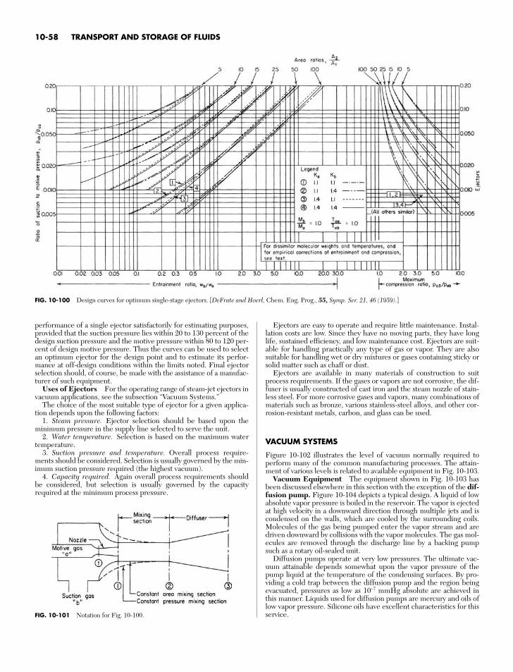
performance of a single ejector satisfactorily for estimating purposes,provided that the suction pressure lies within 20 to 130 percent of thedesign suction pressure and the motive pressure within 80 to 120 per-cent of design motive pressure. Thus the curves can be used to selectan optimum ejector for the design point and to estimate its perfor-mance at off-design conditions within the limits noted. Final ejectorselection should, of course, be made with the assistance of a manufac-turer of such equipment.
Uses of Ejectors For the operating range of steam-jet ejectors invacuum applications, see the subsection “Vacuum Systems.”
The choice of the most suitable type of ejector for a given applica-tion depends upon the following factors:
1. Steam pressure. Ejector selection should be based upon theminimum pressure in the supply line selected to serve the unit.
2. Water temperature. Selection is based on the maximum watertemperature.
3. Suction pressure and temperature. Overall process require-ments should be considered. Selection is usually governed by the min-imum suction pressure required (the highest vacuum).
4. Capacity required. Again overall process requirements shouldbe considered, but selection is usually governed by the capacityrequired at the minimum process pressure.
Ejectors are easy to operate and require little maintenance. Instal-lation costs are low. Since they have no moving parts, they have longlife, sustained efficiency, and low maintenance cost. Ejectors are suit-able for handling practically any type of gas or vapor. They are alsosuitable for handling wet or dry mixtures or gases containing sticky orsolid matter such as chaff or dust.
Ejectors are available in many materials of construction to suitprocess requirements. If the gases or vapors are not corrosive, the dif-fuser is usually constructed of cast iron and the steam nozzle of stain-less steel. For more corrosive gases and vapors, many combinations ofmaterials such as bronze, various stainless-steel alloys, and other cor-rosion-resistant metals, carbon, and glass can be used.
VACUUM SYSTEMS
Figure 10-102 illustrates the level of vacuum normally required toperform many of the common manufacturing processes. The attain-ment of various levels is related to available equipment in Fig. 10-103.
Vacuum Equipment The equipment shown in Fig. 10-103 hasbeen discussed elsewhere in this section with the exception of the dif-fusion pump. Figure 10-104 depicts a typical design. A liquid of lowabsolute vapor pressure is boiled in the reservoir. The vapor is ejectedat high velocity in a downward direction through multiple jets and iscondensed on the walls, which are cooled by the surrounding coils.Molecules of the gas being pumped enter the vapor stream and aredriven downward by collisions with the vapor molecules. The gas mol-ecules are removed through the discharge line by a backing pumpsuch as a rotary oil-sealed unit.
Diffusion pumps operate at very low pressures. The ultimate vac-uum attainable depends somewhat upon the vapor pressure of thepump liquid at the temperature of the condensing surfaces. By pro-viding a cold trap between the diffusion pump and the region beingevacuated, pressures as low as 10−7 mmHg absolute are achieved inthis manner. Liquids used for diffusion pumps are mercury and oils oflow vapor pressure. Silicone oils have excellent characteristics for thisservice.
10-58 TRANSPORT AND STORAGE OF FLUIDS
FIG. 10-100 Design curves for optimum single-stage ejectors. [DeFrate and Hoerl, Chem. Eng. Prog., 55, Symp. Ser. 21, 46 (1959).]
FIG. 10-101 Notation for Fig. 10-100.
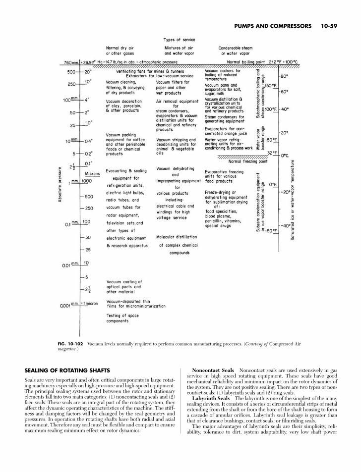
PUMPS AND COMPRESSORS 10-59
FIG. 10-102 Vacuum levels normally required to perform common manufacturing processes. (Courtesy of Compressed Airmagazine.)
SEALING OF ROTATING SHAFTS
Seals are very important and often critical components in large rotat-ing machinery especially on high-pressure and high-speed equipment.The principal sealing systems used between the rotor and stationaryelements fall into two main categories: (1) noncontacting seals and (2)face seals. These seals are an integral part of the rotating system, theyaffect the dynamic operating characteristics of the machine. The stiff-ness and damping factors will be changed by the seal geometry andpressures. In operation the rotating shafts have both radial and axialmovement. Therefore any seal must be flexible and compact to ensuremaximum sealing minimum effect on rotor dynamics.
Noncontact Seals Noncontact seals are used extensively in gasservice in high speed rotating equipment. These seals have goodmechanical reliability and minimum impact on the rotor dynamics ofthe system. They are not positive sealing. There are two types of non-contact seals: (1) labyrinth seals and (2) ring seals.
Labyrinth Seals The labyrinth is one of the simplest of the manysealing devices. It consists of a series of circumferential strips of metalextending from the shaft or from the bore of the shaft housing to forma cascade of annular orifices. Labyrinth seal leakage is greater thanthat of clearance bushings, contact seals, or filmriding seals.
The major advantages of labyrinth seals are their simplicity, reli-ability, tolerance to dirt, system adaptability, very low shaft power
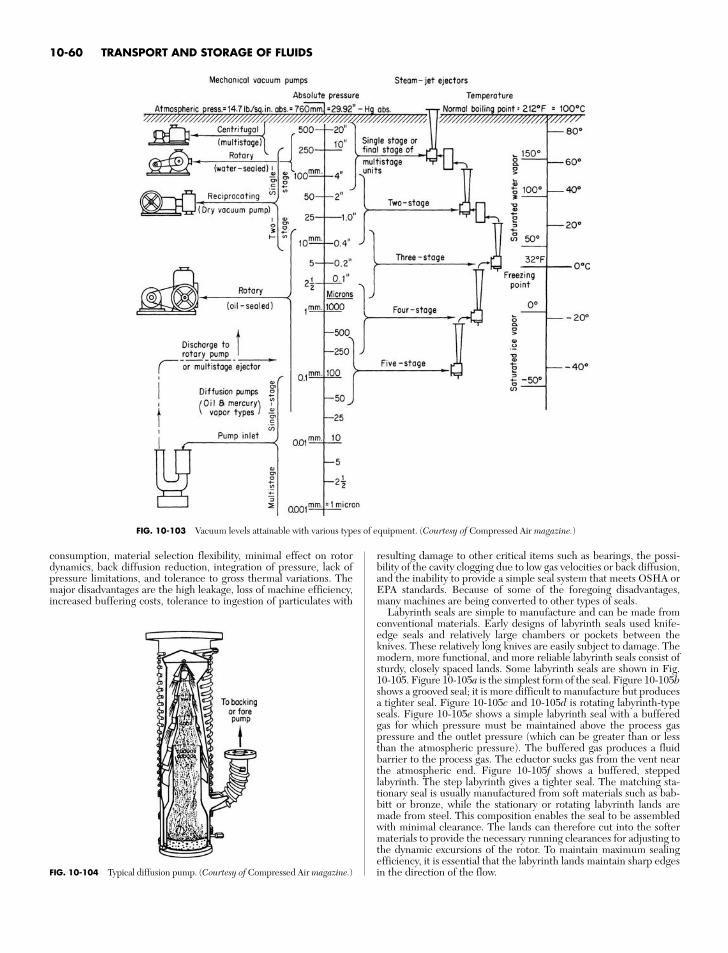
consumption, material selection flexibility, minimal effect on rotordynamics, back diffusion reduction, integration of pressure, lack ofpressure limitations, and tolerance to gross thermal variations. Themajor disadvantages are the high leakage, loss of machine efficiency,increased buffering costs, tolerance to ingestion of particulates with
resulting damage to other critical items such as bearings, the possi-bility of the cavity clogging due to low gas velocities or back diffusion,and the inability to provide a simple seal system that meets OSHA orEPA standards. Because of some of the foregoing disadvantages,many machines are being converted to other types of seals.
Labyrinth seals are simple to manufacture and can be made fromconventional materials. Early designs of labyrinth seals used knife-edge seals and relatively large chambers or pockets between theknives. These relatively long knives are easily subject to damage. Themodern, more functional, and more reliable labyrinth seals consist ofsturdy, closely spaced lands. Some labyrinth seals are shown in Fig.10-105. Figure 10-105a is the simplest form of the seal. Figure 10-105bshows a grooved seal; it is more difficult to manufacture but producesa tighter seal. Figure 10-105c and 10-105d is rotating labyrinth-typeseals. Figure 10-105e shows a simple labyrinth seal with a bufferedgas for which pressure must be maintained above the process gaspressure and the outlet pressure (which can be greater than or lessthan the atmospheric pressure). The buffered gas produces a fluidbarrier to the process gas. The eductor sucks gas from the vent nearthe atmospheric end. Figure 10-105f shows a buffered, steppedlabyrinth. The step labyrinth gives a tighter seal. The matching sta-tionary seal is usually manufactured from soft materials such as bab-bitt or bronze, while the stationary or rotating labyrinth lands aremade from steel. This composition enables the seal to be assembledwith minimal clearance. The lands can therefore cut into the softermaterials to provide the necessary running clearances for adjusting tothe dynamic excursions of the rotor. To maintain maximum sealingefficiency, it is essential that the labyrinth lands maintain sharp edgesin the direction of the flow.
10-60 TRANSPORT AND STORAGE OF FLUIDS
FIG. 10-103 Vacuum levels attainable with various types of equipment. (Courtesy of Compressed Air magazine.)
FIG. 10-104 Typical diffusion pump. (Courtesy of Compressed Air magazine.)
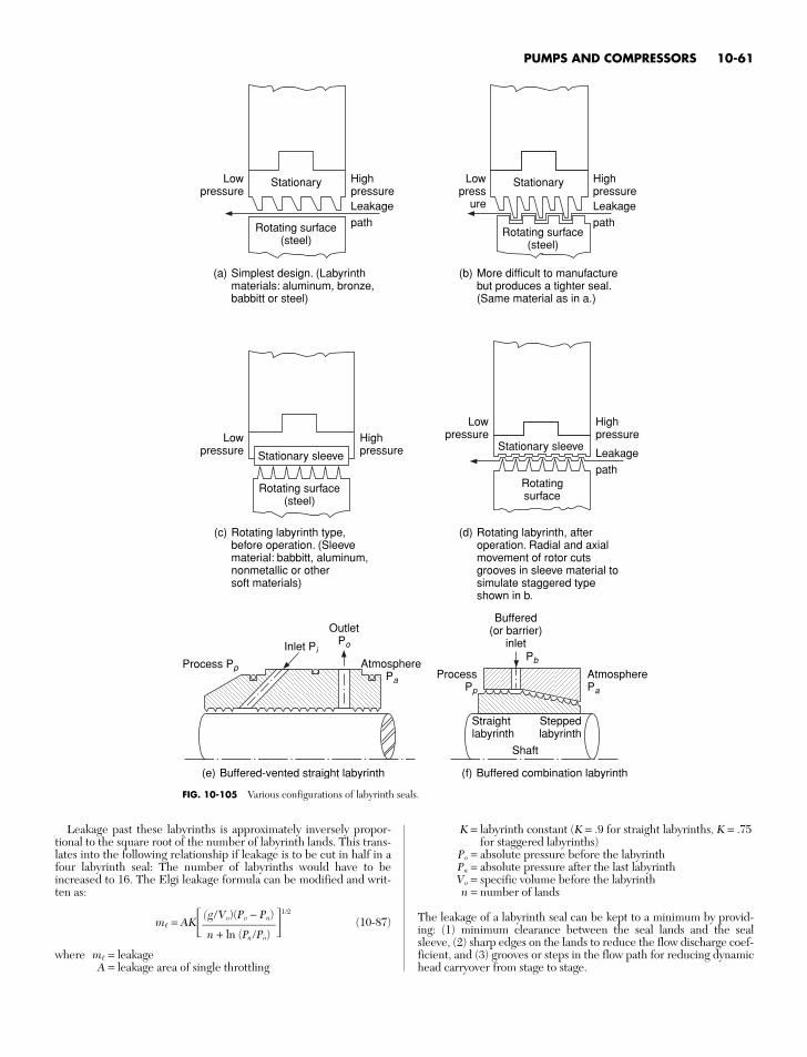
Leakage past these labyrinths is approximately inversely propor-tional to the square root of the number of labyrinth lands. This trans-lates into the following relationship if leakage is to be cut in half in afour labyrinth seal: The number of labyrinths would have to beincreased to 16. The Elgi leakage formula can be modified and writ-ten as:
m = AK 1/2
(10-87)
where m = leakageA = leakage area of single throttling
(g/Vo)(Po − Pn)n + ln (Pn /Po)
PUMPS AND COMPRESSORS 10-61
FIG. 10-105 Various configurations of labyrinth seals.
Stationary
Rotating surface(steel)
Simplest design. (Labyrinthmaterials: aluminum, bronze,babbitt or steel)
Lowpressure
HighpressureLeakage
path
Stationary
Rotating surface(steel)
Lowpress
ure
HighpressureLeakage
path
(a) More difficult to manufacturebut produces a tighter seal.(Same material as in a.)
(b)
Rotating labyrinth type,before operation. (Sleevematerial: babbitt, aluminum,nonmetallic or othersoft materials)
(c)
Rotating surface(steel)
Lowpressure
HighpressureStationary sleeve
Rotating labyrinth, afteroperation. Radial and axialmovement of rotor cutsgrooves in sleeve material tosimulate staggered typeshown in b.
(d)
Stationary sleeve
Rotatingsurface
Lowpressure
Highpressure
Leakage
path
Buffered-vented straight labyrinth(e)
Process Pp
Inlet Pi
OutletPo
Atmosphere Pa
ProcessPp
Buffered(or barrier)
inlet
AtmospherePa
Straightlabyrinth
Shaft
Buffered combination labyrinth(f)
Steppedlabyrinth
Pb
K = labyrinth constant (K = .9 for straight labyrinths, K = .75for staggered labyrinths)
Po = absolute pressure before the labyrinthPn = absolute pressure after the last labyrinthVo = specific volume before the labyrinthn = number of lands
The leakage of a labyrinth seal can be kept to a minimum by provid-ing: (1) minimum clearance between the seal lands and the sealsleeve, (2) sharp edges on the lands to reduce the flow discharge coef-ficient, and (3) grooves or steps in the flow path for reducing dynamichead carryover from stage to stage.
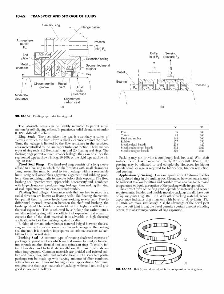
The labyrinth sleeve can be flexibly mounted to permit radialmotion for self-aligning effects. In practice, a radial clearance of under0.008 is difficult to achieve.
Ring Seals The restrictive ring seal is essentially a series ofsleeves in which the bores form a small clearance around the shaft.Thus, the leakage is limited by the flow resistance in the restrictedarea and controlled by the laminar or turbulent friction. There are twotypes of ring seals: (1) fixed seal rings and (2) floating seal rings. Thefloating rings permit a much smaller leakage; they can be either thesegmented type as shown in Fig. 10-106a or the rigid type as shown inFig. 10-106b.
Fixed Seal Rings The fixed-seal ring consists of a long sleeveaffixed to a housing in which the shaft rotates with small clearances.Long assemblies must be used to keep leakage within a reasonablelimit. Long seal assemblies aggravate alignment and rubbing prob-lems, thus requiring shafts to operate below their capacity. The fixedbushing seal operates with appreciable eccentricity and, combinedwith large clearances, produces large leakages, thus making this kindof seal impractical where leakage is undesirable.
Floating Seal Rings Clearance seals that are free to move in aradial direction are known as floating seals. The floating characteris-tics permit them to move freely, thus avoiding severe rubs. Due todifferential thermal expansion between the shaft and bushing, thebushings should be made of material with a higher coefficient ofthermal expansion. This is achieved by shrinking the carbon into ametallic retaining ring with a coefficient of expansion that equals orexceeds that of the shaft material. It is advisable in high shearingapplications to lock the bushings against rotation.
Buildup of dirt and other foreign material lodged between the sealring and seat will create an excessive spin and damage on the floatingseal ring unit. It is therefore improper to use soft material such as bab-bitt and silver as seal rings.
Packing Seal A common type of rotating shaft seal consists ofpacking composed of fibers which are first woven, twisted, or braidedinto strands and then formed into coils, spirals, or rings. To ensure ini-tial lubrication and to facilitate installation, the basic materials areoften impregnated. Common materials are braided and twisted rub-ber and duck, flax, jute, and metallic braids. The so-called plasticpackings can be made up with varying amounts of fiber combinedwith a binder and lubricant for high-speed applications. Maximumtemperatures that base materials of packings withstand and still givegood service are as follows:
°C °F
Flax 38 100Cotton 93 200Duck and rubber 149 300Rubber 177 350Metallic (lead-based) 218 425Metallic (aluminum-based) 552 1025Metallic (copper-based) 829 1525
Packing may not provide a completely leak-free seal. With shaftsurface speeds less than approximately 2.5 m/s (500 ft/min), thepacking may be adjusted to seal completely. However, for higherspeeds some leakage is required for lubrication, friction reduction,and cooling.
Application of Packing Coils and spirals are cut to form closed ornearly closed rings in the stuffing box. Clearance between ends shouldbe sufficient to allow for fitting and possible expansion due to increasedtemperature or liquid absorption of the packing while in operation.
The correct form of the ring joint depends on materials and servicerequirements. Braided and flexible metallic packings usually have buttor square joints (Fig. 10-107a). With other packing material, serviceexperience indicates that rings cut with bevel or skive joints (Fig.10-107b) are more satisfactory. A slight advantage of the bevel jointover the butt joint is that the bevel permits a certain amount of slidingaction, thus absorbing a portion of ring expansion.
10-62 TRANSPORT AND STORAGE OF FLUIDS
( a )
( b )
FIG. 10-107 Butt (a) and skive (b) joints for compression packing rings.
FIG. 10-106 Floating-type restrictive ring seal.
( a ) ( b )
Outlet
Bearing
Bufferinlet Pa
Sensingpressure Ps
Process PpPo
Radialvent
Circumferentialgroove Small
radialclearanceModerate
clearance
Metalchamber
Endplate
Atmosphere(outlet)
Po
Seal housingFlange gasket
Extension spring
Processgas(inlet) PL
Segmented metal retainer
Key
Segmentedcarbon seal
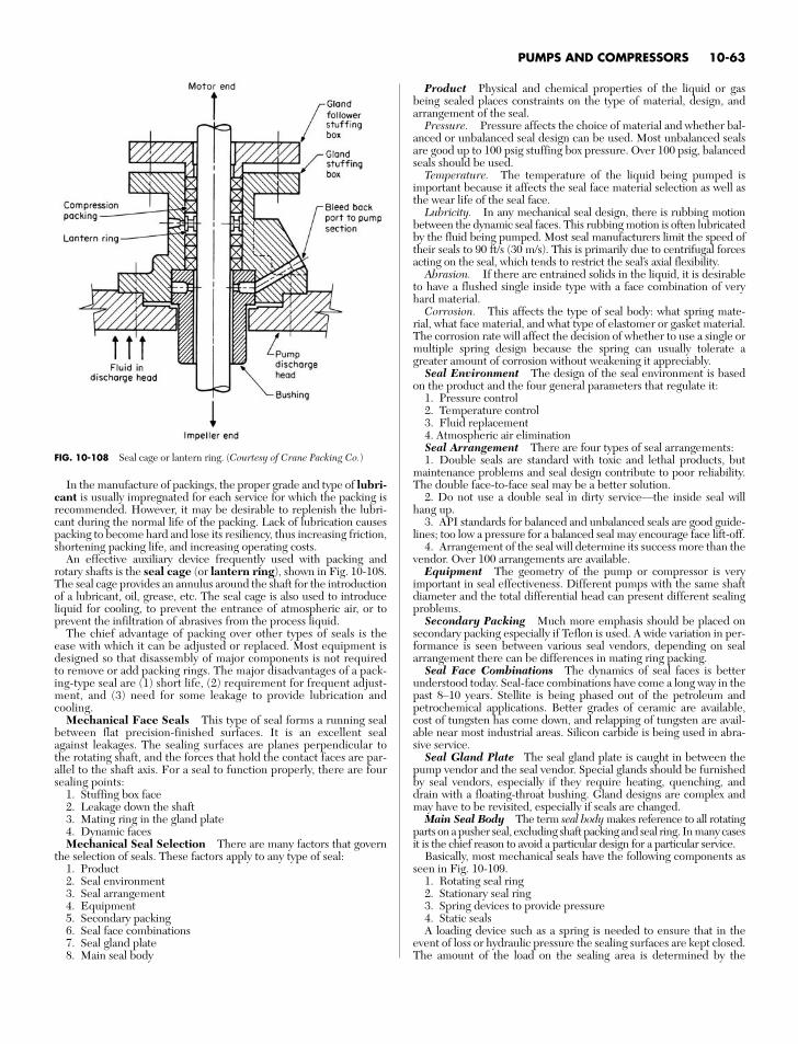
In the manufacture of packings, the proper grade and type of lubri-cant is usually impregnated for each service for which the packing isrecommended. However, it may be desirable to replenish the lubri-cant during the normal life of the packing. Lack of lubrication causespacking to become hard and lose its resiliency, thus increasing friction,shortening packing life, and increasing operating costs.
An effective auxiliary device frequently used with packing androtary shafts is the seal cage (or lantern ring), shown in Fig. 10-108.The seal cage provides an annulus around the shaft for the introductionof a lubricant, oil, grease, etc. The seal cage is also used to introduceliquid for cooling, to prevent the entrance of atmospheric air, or toprevent the infiltration of abrasives from the process liquid.
The chief advantage of packing over other types of seals is theease with which it can be adjusted or replaced. Most equipment isdesigned so that disassembly of major components is not requiredto remove or add packing rings. The major disadvantages of a pack-ing-type seal are (1) short life, (2) requirement for frequent adjust-ment, and (3) need for some leakage to provide lubrication andcooling.
Mechanical Face Seals This type of seal forms a running sealbetween flat precision-finished surfaces. It is an excellent sealagainst leakages. The sealing surfaces are planes perpendicular tothe rotating shaft, and the forces that hold the contact faces are par-allel to the shaft axis. For a seal to function properly, there are foursealing points:
1. Stuffing box face2. Leakage down the shaft3. Mating ring in the gland plate4. Dynamic facesMechanical Seal Selection There are many factors that govern
the selection of seals. These factors apply to any type of seal:1. Product2. Seal environment3. Seal arrangement4. Equipment5. Secondary packing6. Seal face combinations7. Seal gland plate8. Main seal body
Product Physical and chemical properties of the liquid or gasbeing sealed places constraints on the type of material, design, andarrangement of the seal.
Pressure. Pressure affects the choice of material and whether bal-anced or unbalanced seal design can be used. Most unbalanced sealsare good up to 100 psig stuffing box pressure. Over 100 psig, balancedseals should be used.
Temperature. The temperature of the liquid being pumped isimportant because it affects the seal face material selection as well asthe wear life of the seal face.
Lubricity. In any mechanical seal design, there is rubbing motionbetween the dynamic seal faces. This rubbing motion is often lubricatedby the fluid being pumped. Most seal manufacturers limit the speed oftheir seals to 90 ft/s (30 m/s). This is primarily due to centrifugal forcesacting on the seal, which tends to restrict the seal’s axial flexibility.
Abrasion. If there are entrained solids in the liquid, it is desirableto have a flushed single inside type with a face combination of veryhard material.
Corrosion. This affects the type of seal body: what spring mate-rial, what face material, and what type of elastomer or gasket material.The corrosion rate will affect the decision of whether to use a single ormultiple spring design because the spring can usually tolerate agreater amount of corrosion without weakening it appreciably.
Seal Environment The design of the seal environment is basedon the product and the four general parameters that regulate it:
1. Pressure control2. Temperature control3. Fluid replacement4. Atmospheric air eliminationSeal Arrangement There are four types of seal arrangements:1. Double seals are standard with toxic and lethal products, but
maintenance problems and seal design contribute to poor reliability.The double face-to-face seal may be a better solution.
2. Do not use a double seal in dirty service—the inside seal willhang up.
3. API standards for balanced and unbalanced seals are good guide-lines; too low a pressure for a balanced seal may encourage face lift-off.
4. Arrangement of the seal will determine its success more than thevendor. Over 100 arrangements are available.
Equipment The geometry of the pump or compressor is veryimportant in seal effectiveness. Different pumps with the same shaftdiameter and the total differential head can present different sealingproblems.
Secondary Packing Much more emphasis should be placed onsecondary packing especially if Teflon is used. A wide variation in per-formance is seen between various seal vendors, depending on sealarrangement there can be differences in mating ring packing.
Seal Face Combinations The dynamics of seal faces is betterunderstood today. Seal-face combinations have come a long way in thepast 8–10 years. Stellite is being phased out of the petroleum andpetrochemical applications. Better grades of ceramic are available,cost of tungsten has come down, and relapping of tungsten are avail-able near most industrial areas. Silicon carbide is being used in abra-sive service.
Seal Gland Plate The seal gland plate is caught in between thepump vendor and the seal vendor. Special glands should be furnishedby seal vendors, especially if they require heating, quenching, anddrain with a floating-throat bushing. Gland designs are complex andmay have to be revisited, especially if seals are changed.
Main Seal Body The term seal body makes reference to all rotatingparts on a pusher seal, excluding shaft packing and seal ring. In many casesit is the chief reason to avoid a particular design for a particular service.
Basically, most mechanical seals have the following components asseen in Fig. 10-109.
1. Rotating seal ring2. Stationary seal ring3. Spring devices to provide pressure4. Static sealsA loading device such as a spring is needed to ensure that in the
event of loss or hydraulic pressure the sealing surfaces are kept closed.The amount of the load on the sealing area is determined by the
PUMPS AND COMPRESSORS 10-63
FIG. 10-108 Seal cage or lantern ring. (Courtesy of Crane Packing Co.)
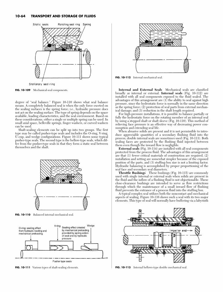
degree of “seal balance.” Figure 10-110 shows what seal balancemeans. A completely balanced seal is when the only force exerted onthe sealing surfaces is the spring force; i.e., hydraulic pressure doesnot act on the sealing surface. The type of spring depends on the spaceavailable, loading characteristics, and the seal environment. Based onthese considerations, either a single or multiple spring can be used. Insmall axial space, belleville springs, finger washers, or curved washerscan be used.
Shaft-sealing elements can be split up into two groups. The firsttype may be called pusher-type seals and includes the O-ring, V-ring,U-cup, and wedge configurations. Figure 10-111 shows some typicalpusher-type seals. The second type is the bellow-type seals, which dif-fer from the pusher-type seals in that they form a static seal betweenthemselves and the shaft.
Internal and External Seals Mechanical seals are classifiedbroadly as internal or external. Internal seals (Fig. 10-112) areinstalled with all seal components exposed to the fluid sealed. Theadvantages of this arrangement are (1) the ability to seal against highpressure, since the hydrostatic force is normally in the same directionas the spring force; (2) protection of seal parts from external mechan-ical damage; and (3) reduction in the shaft length required.
For high-pressure installations, it is possible to balance partially orfully the hydrostatic force on the rotating member of an internal sealby using a stepped shaft or shaft sleeve (Fig. 10-110). This method ofrelieving face pressure is an effective way of decreasing power con-sumption and extending seal life.
When abrasive solids are present and it is not permissible to intro-duce appreciable quantities of a secondary flushing fluid into theprocess, double internal seals are sometimes used (Fig. 10-113). Bothsealing faces are protected by the flushing fluid injected betweenthem even though the inward flow is negligible.
External seals (Fig. 10-114) are installed with all seal componentsprotected from the process fluid. The advantages of this arrangementare that (1) fewer critical materials of construction are required, (2)installation and setting are somewhat simpler because of the exposedposition of the parts, and (3) stuffing-box size is not a limiting factor.Hydraulic balancing is accomplished by proper proportioning of theseal face and secondary seal diameters.
Throttle Bushings These bushings (Fig. 10-115) are commonlyused with single internal or external seals when solids are present inthe fluid and the inflow of a flushing fluid is not objectionable. Theseclose-clearance bushings are intended to serve as flow restrictionsthrough which the maintenance of a small inward flow of flushingfluid prevents the entrance of a process fluid into the stuffing box.
A typical complex seal utilizes both the noncontact and mechanicalaspects of sealing. Figure 10-116 shows such a seal with its two majorelements. This type of seal will normally have buffering via a labyrinth
10-64 TRANSPORT AND STORAGE OF FLUIDS
FIG. 10-113 Internal bellows-type double mechanical seal.FIG. 10-111 Various types of shaft-sealing elements.
FIG. 10-110 Balanced internal mechanical seal.
FIG. 10-112 Internal mechanical seal.
FIG. 10-109 Mechanical-seal components.
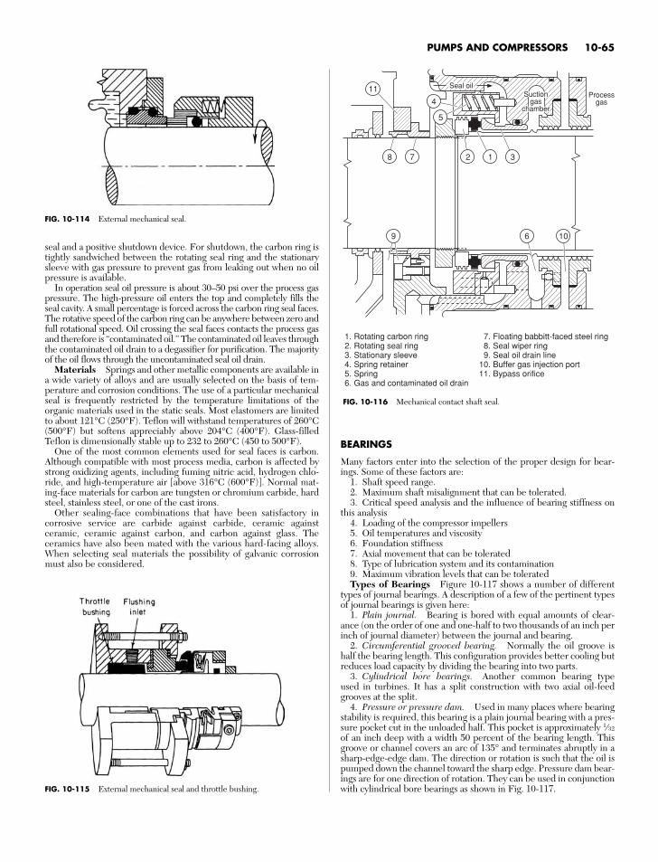
seal and a positive shutdown device. For shutdown, the carbon ring istightly sandwiched between the rotating seal ring and the stationarysleeve with gas pressure to prevent gas from leaking out when no oilpressure is available.
In operation seal oil pressure is about 30–50 psi over the process gaspressure. The high-pressure oil enters the top and completely fills theseal cavity. A small percentage is forced across the carbon ring seal faces.The rotative speed of the carbon ring can be anywhere between zero andfull rotational speed. Oil crossing the seal faces contacts the process gasand therefore is “contaminated oil.” The contaminated oil leaves throughthe contaminated oil drain to a degassifier for purification. The majorityof the oil flows through the uncontaminated seal oil drain.
Materials Springs and other metallic components are available ina wide variety of alloys and are usually selected on the basis of tem-perature and corrosion conditions. The use of a particular mechanicalseal is frequently restricted by the temperature limitations of theorganic materials used in the static seals. Most elastomers are limitedto about 121°C (250°F). Teflon will withstand temperatures of 260°C(500°F) but softens appreciably above 204°C (400°F). Glass-filledTeflon is dimensionally stable up to 232 to 260°C (450 to 500°F).
One of the most common elements used for seal faces is carbon.Although compatible with most process media, carbon is affected bystrong oxidizing agents, including fuming nitric acid, hydrogen chlo-ride, and high-temperature air [above 316°C (600°F)]. Normal mat-ing-face materials for carbon are tungsten or chromium carbide, hardsteel, stainless steel, or one of the cast irons.
Other sealing-face combinations that have been satisfactory incorrosive service are carbide against carbide, ceramic againstceramic, ceramic against carbon, and carbon against glass. Theceramics have also been mated with the various hard-facing alloys.When selecting seal materials the possibility of galvanic corrosionmust also be considered.
BEARINGS
Many factors enter into the selection of the proper design for bear-ings. Some of these factors are:
1. Shaft speed range.2. Maximum shaft misalignment that can be tolerated.3. Critical speed analysis and the influence of bearing stiffness on
this analysis4. Loading of the compressor impellers5. Oil temperatures and viscosity6. Foundation stiffness7. Axial movement that can be tolerated8. Type of lubrication system and its contamination9. Maximum vibration levels that can be toleratedTypes of Bearings Figure 10-117 shows a number of different
types of journal bearings. A description of a few of the pertinent typesof journal bearings is given here:
1. Plain journal. Bearing is bored with equal amounts of clear-ance (on the order of one and one-half to two thousands of an inch perinch of journal diameter) between the journal and bearing.
2. Circumferential grooved bearing. Normally the oil groove ishalf the bearing length. This configuration provides better cooling butreduces load capacity by dividing the bearing into two parts.
3. Cylindrical bore bearings. Another common bearing typeused in turbines. It has a split construction with two axial oil-feedgrooves at the split.
4. Pressure or pressure dam. Used in many places where bearingstability is required, this bearing is a plain journal bearing with a pres-sure pocket cut in the unloaded half. This pocket is approximately 1⁄32
of an inch deep with a width 50 percent of the bearing length. Thisgroove or channel covers an arc of 135° and terminates abruptly in asharp-edge-edge dam. The direction or rotation is such that the oil ispumped down the channel toward the sharp edge. Pressure dam bear-ings are for one direction of rotation. They can be used in conjunctionwith cylindrical bore bearings as shown in Fig. 10-117.
PUMPS AND COMPRESSORS 10-65
FIG. 10-114 External mechanical seal.
FIG. 10-115 External mechanical seal and throttle bushing.
Seal oilSeal oilSeal oilProcess
gasSuctionSuction
gaschamberchamber
Suctiongas
chamber
1069
8 7 2 1 3
1.2.3.4.5.6.
Rotating carbon ringRotating seal ringStationary sleeveSpring retainerSpringGas and contaminated oil drain
7.8.9.
10.11.
Floating babbitt-faced steel ringSeal wiper ringSeal oil drain lineBuffer gas injection portBypass orifice
11
4
5
FIG. 10-116 Mechanical contact shaft seal.
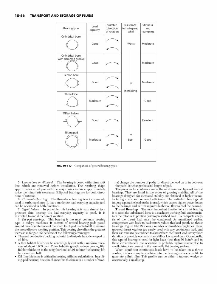
5. Lemon bore or elliptical. This bearing is bored with shims splitline, which are removed before installation. The resulting shapeapproximates an ellipse with the major axis clearance approximatelytwice the minor axis clearance. Elliptical bearings are for both direc-tions of rotation.
6. Three-lobe bearing. The three-lobe bearing is not commonlyused in turbomachines. It has a moderate load-carrying capacity andcan be operated in both directions.
7. Offset halves. In principle, this bearing acts very similar to apressure dam bearing. Its load-carrying capacity is good. It isrestricted to one direction of rotation.
8. Tilt-pad bearings. This bearing is the most common bearingtype in today’s machines. It consists of several bearing pads posedaround the circumference of the shaft. Each pad is able to tilt to assumethe most effective working position. This bearing also offers the greatestincrease in fatigue life because of the following advantages:• Thermal conductive backing material to dissipate heat developed in
oil film.• A thin babbitt layer can be centrifugally cast with a uniform thick-
ness of about 0.005 inch. Thick babbitts greatly reduce bearing life.Babbitt thickness in the neighborhood of .01 reduce the bearing lifeby more than half.
• Oil film thickness is critical in bearing stiffness calculations. In a tilt-ing-pad bearing, one can change this thickness in a number of ways:
(a) change the number of pads; (b) direct the load on or in betweenthe pads; (c) change the axial length of pad.The previous list contains some of the most common types of journal
bearings. They are listed in the order of growing stability. All of thebearings designed for increased stability are obtained at higher manu-facturing costs and reduced efficiency. The antiwhirl bearings allimpose a parasitic load on the journal, which causes higher-power lossesto the bearings and in turn requires higher oil flow to cool the bearing.
Thrust Bearings The most important function of a thrust bearingis to resist the unbalanced force in a machine’s working fluid and to main-tain the rotor in its position (within prescribed limits). A complete analy-sis of the thrust load must be conducted. As mentioned earlier,compressors with back-to-back rotors reduce this load greatly on thrustbearings. Figure 10-118 shows a number of thrust-bearing types. Plain,grooved thrust washers are rarely used with any continuous load, andtheir use tends to be confined to cases where the thrust load is very shortduration or possibly occurs at standstill or low speed only. Occasionally,this type of bearing is used for light loads (less than 50 lb/in2), and inthese circumstances the operation is probably hydrodynamic due tosmall distortions present in the nominally flat bearing surface.
When significant continuous loads have to be taken on a thrustwasher, it is necessary to machine into the bearing surface a profile togenerate a fluid film. This profile can be either a tapered wedge oroccasionally a small step.
10-66 TRANSPORT AND STORAGE OF FLUIDS
Bearing typeLoad
capacity
Suitabledirection
of rotation
Resistanceto half-speed
whirl
Stiffnessand
damping
Cylindrical bore
Cylindrical borewith dammed groove
Lemon bore
Three lobe
Moderate
Good
Good
Good Moderate
Good
Moderate
Good
Moderate
Moderate
Excellent
Good
Offset halves
Tilting pad
Worst
Best
Increasing
FIG. 10-117 Comparison of general bearing types.
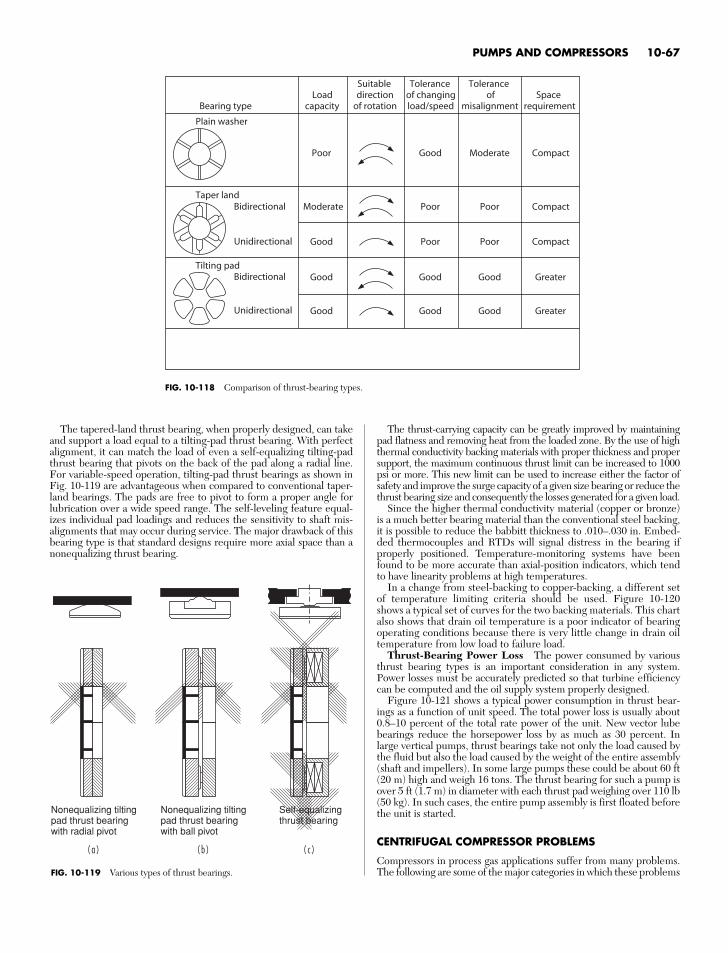
The tapered-land thrust bearing, when properly designed, can takeand support a load equal to a tilting-pad thrust bearing. With perfectalignment, it can match the load of even a self-equalizing tilting-padthrust bearing that pivots on the back of the pad along a radial line.For variable-speed operation, tilting-pad thrust bearings as shown inFig. 10-119 are advantageous when compared to conventional taper-land bearings. The pads are free to pivot to form a proper angle forlubrication over a wide speed range. The self-leveling feature equal-izes individual pad loadings and reduces the sensitivity to shaft mis-alignments that may occur during service. The major drawback of thisbearing type is that standard designs require more axial space than anonequalizing thrust bearing.
The thrust-carrying capacity can be greatly improved by maintainingpad flatness and removing heat from the loaded zone. By the use of highthermal conductivity backing materials with proper thickness and propersupport, the maximum continuous thrust limit can be increased to 1000psi or more. This new limit can be used to increase either the factor ofsafety and improve the surge capacity of a given size bearing or reduce thethrust bearing size and consequently the losses generated for a given load.
Since the higher thermal conductivity material (copper or bronze)is a much better bearing material than the conventional steel backing,it is possible to reduce the babbitt thickness to .010–.030 in. Embed-ded thermocouples and RTDs will signal distress in the bearing ifproperly positioned. Temperature-monitoring systems have beenfound to be more accurate than axial-position indicators, which tendto have linearity problems at high temperatures.
In a change from steel-backing to copper-backing, a different setof temperature limiting criteria should be used. Figure 10-120shows a typical set of curves for the two backing materials. This chartalso shows that drain oil temperature is a poor indicator of bearingoperating conditions because there is very little change in drain oiltemperature from low load to failure load.
Thrust-Bearing Power Loss The power consumed by variousthrust bearing types is an important consideration in any system.Power losses must be accurately predicted so that turbine efficiencycan be computed and the oil supply system properly designed.
Figure 10-121 shows a typical power consumption in thrust bear-ings as a function of unit speed. The total power loss is usually about0.8–10 percent of the total rate power of the unit. New vector lubebearings reduce the horsepower loss by as much as 30 percent. Inlarge vertical pumps, thrust bearings take not only the load caused bythe fluid but also the load caused by the weight of the entire assembly(shaft and impellers). In some large pumps these could be about 60 ft(20 m) high and weigh 16 tons. The thrust bearing for such a pump isover 5 ft (1.7 m) in diameter with each thrust pad weighing over 110 lb(50 kg). In such cases, the entire pump assembly is first floated beforethe unit is started.
CENTRIFUGAL COMPRESSOR PROBLEMS
Compressors in process gas applications suffer from many problems.The following are some of the major categories in which these problems
PUMPS AND COMPRESSORS 10-67
LoadcapacityBearing type
Suitabledirection
of rotation
Toleranceof changingload/speed
Toleranceof
misalignmentSpace
requirement
Bidirectional
Unidirectional
Bidirectional
Unidirectional
Good
Good
Good
Moderate
Poor
Plain washer
Taper land
Tilting pad
Poor
Good
Good
Poor
Good
Poor
Good
Good
Poor
Moderate
Compact
Greater
Greater
Compact
Compact
FIG. 10-118 Comparison of thrust-bearing types.
( a )
Nonequalizing tiltingpad thrust bearingwith radial pivot
( b ) ( c )
Nonequalizing tiltingpad thrust bearingwith ball pivot
Self-equalizingthrust bearing
FIG. 10-119 Various types of thrust bearings.
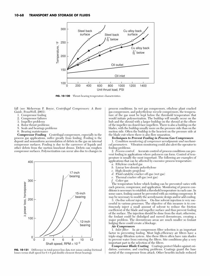
fall (see Meherwan P. Boyce, Centrifugal Compressors: A BasicGuide, PennWell, 2003):
1. Compressor fouling2. Compressor failures3. Impeller problems4. Rotor thrust problems5. Seals and bearings problems6. Bearing maintenanceCompressor Fouling Centrifugal compressors, especially in the
process gas applications, suffer greatly from fouling. Fouling is thedeposit and nonuniform accumulation of debris in the gas on internalcompressor surfaces. Fouling is due to the carryover of liquids andother debris from the suction knockout drums. Debris can roughencompressor surfaces. Polymerization can occur also due to changes in
process conditions. In wet gas compressors, ethylene plant crackedgas compressors, and polyethylene recycle compressors, the tempera-ture of the gas must be kept below the threshold temperature thatwould initiate polymerization. The buildup will usually occur on thehub and the shroud with a larger buildup on the shroud at the elbowof the impeller on closed-face impellers. There is also a buildup on theblades, with the buildup usually more on the pressure side than on thesuction side. Often the buildup is the heaviest on the pressure side atthe blade exit where there is also flow separation.
Techniques to Prevent Fouling in Process Gas Compressors1. Condition monitoring of compressor aerodynamic and mechani-
cal parameters. Vibration monitoring could also alert the operator tofouling problems.
2. Process control. Accurate control of process conditions can pre-vent fouling in applications where polymers can form. Control of tem-perature is usually the most important. The following are examples ofapplications that can be affected by excessive process temperature:
a. Ethylene cracked gasb. Linear low-density polyethylenec. High-density propylened. Fluid catalytic cracker off-gas (wet gas)e. Thermal cracker off-gas (wet gas)f. Coker gasThe temperature below which fouling can be prevented varies with
each process, compressor, and application. Monitoring of process con-ditions is necessary to establish a threshold temperature in each case. Insome cases, fouling cannot be prevented with an existing compressor. Itmay be necessary to modify the aerodynamic design and/or add cooling.
3. On-line solvent injection. On-line solvent injection is very suc-cessful in various processes. The objective of this measure is to con-tinuously inject a small amount of solvent to reduce the frictioncoefficient of the blade and impeller surface and thus prevent foulingof the surface. The injection should be done from the start; otherwise,the foulant could be dislodged and moved downstream, creating amajor problem. The downstream areas are much smaller so foulantlodging there could create a blockage.
Air Compressors1. Inlet filter. In air compressors filter selection is an important
factor in preventing fouling. Most high-efficiency air filters have atriple-stage filtration system. Also these filters often have rain shadesto prevent water from entering the filters. Site conditions play a veryimportant part in the selection of the filters.
Compressor Blade Coating Coatings protect blades against oxi-dation, corrosion, and cracking problems. Coatings guard the basemetal of the compressor from attack. Other benefits include reduced
10-68 TRANSPORT AND STORAGE OF FLUIDS
300
250
200
150
1000 200 400 600
Unit thrust load, PSI
Tem
pera
ture
,°F
800 1000 1200 1400
Steel backsurface
Cu alloy backsurfaceSteel back
below′′516
Cu alloy back
Oil outlet
Oil inlet
below′′516
FIG. 10-120 Thrust-bearing temperature characteristics.
300
400
200
100
00 2 4 6 8
Shaft speed, RPM × 10–3
∆ po
wer
loss
, hor
sepo
wer
10 12
17-inchbearing
15-inchbearing
12-inchbearing
FIG. 10-121 Difference in total-power-loss data test minus catalog frictionallosses versus shaft speed for 6 × 6 pad double-element thrust bearings.
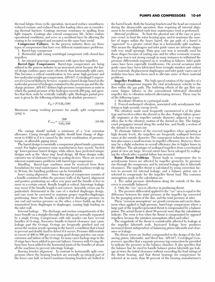
thermal fatigue from cyclic operation, increased surface smoothness,reduced erosion, and reduced heat flux loading when one is consider-ing thermal barriers. Coatings increase resistance to spalling fromlight impacts. Coatings also extend compressor life, better endureoperational conditions, and serve as a sacrificial layer by allowing thecoating to be restripped and recoated on the same base metal.
Compressor Failures In the process industry there are threetypes of compressors that have very different maintenance problems:
1. Barrel-type compressor2. Horizontal split casing centrifugal compressor with closed-face
impellers3. Air integral gear-type compressor with open-face impellersBarrel-Type Compressors Barrel-type compressors are being
utilized in the process industry to an increased extent because the bar-rel design confines gases more effectively than horizontally split cases.This becomes a critical consideration in two areas: high-pressure andlow-molecular-weight gas compression. API-617, Centrifugal Compres-sors for General Refinery Services, requires a barrel design based on themolecular percent of hydrogen contained in the process gas and the dis-charge pressure. API-617 defines high-pressure compressors as units inwhich the partial pressure of the hydrogen exceeds 200 psig, and speci-fies that these units be vertically (radially) split. Hydrogen partial pres-sure is given by the following relationship (in absolute pressures):
PH2 = P(%H2/100) (10-88)
Maximum casing working pressure for axially split compressors(psig) is
Pcasing = (10-89)
The casings should include a minimum of a 1⁄8-in corrosionallowance. Casing strength and rigidity should limit change of align-ment to 0.002 in if it is caused by the worst combination of pressure,torque, or allowable piping stress.
The barrel design is essentially a compressor placed inside a pressurevessel. For higher pressures some manufacturers have merely “beefedup” lower-pressure barrel designs, while others, have perfected uniquedesigns such as the “shear ring” head design. All these designs makeextensive use of elastomer O-rings as sealing devices. There are severalinherent maintenance problems with barrel-type compressors:
Handling. Barrel-type machines must be removed from theirfoundations for total maintenance. Because barrel machines weigh upto 30 tons, the handling problems can be formidable.
Inner casing alignment. Since this type of compressor consists ofa bundle contained within the pressure walls of the barrel, alignmentand positive positioning are often very poor and the bundle is free tomove to a certain extent. Bundle length is critical. Interstage leakagemay occur if the bundle length is not correct. Assembly errors can beparticularly detrimental in the case of a stacked diaphragm design,and care must be exercised to maintain proper impeller-diaphragmpositioning. Since the bundle is subjected to discharge pressure onone end and suction pressure on the other, a force builds up that istransmitted from diaphragm to diaphragm, causing high loading onthe inlet wall.
Internal leakage. The discharge and suction compartments of theinner bundle on a straight-through flow design are normally separatedby a single O-ring. Compressors with side nozzles can have severalbundles of O-rings, Excessive bundle-to-barrel clearance may causeleakage past the O-rings. O-rings are frequently pinched and cutacross the suction nozzle opening in the barrel, a condition that is hardto prevent and doubly hard to detect if it occurs. Pressure differentialsin excess of 400 to 500 psi even using good design practice can causeextrusion and failure of the O-rings. In many cases backup rings to theO-rings have been added to prevent failures. Grooves with O-ring rib-bons have been added to the horizontal joints of the bundles of almostall the machines to prevent interstage leakage.
Bearing bracket alignment. In contrast to horizontally split com-pressors where the bearing brackets are normally an integral part ofthe lower case half, in barrel machines bearing brackets are bolted to
200%H2/100
the barrel heads. Both the bearing brackets and the head are removedduring the disassembly operation, thus requiring all internal align-ment to be reestablished each time maintenance work is performed.
Material problems. To limit the physical size of the case or pres-sure vessel, to limit the rotor bearing span, and to maximize the num-ber of stages within the heavy barrel, the gas path of a barrel is“squeezed” to a greater extent than in a horizontally split machine.This means the diaphragms and inlet guide vanes are intricate shapeswith very small openings. Plain gray cast iron is normally used forthese shapes because of casting ease and for other economic reasons.The gray iron is not strong enough in many instances to withstand thepressure differentials imposed on it, resulting in failures. Inlet guidevanes have been especially troublesome. On several occasions inletguide vanes have been fabricated from wrought stainless and carbonsteel materials. Replacement diaphragms and inlet guide vanes cast ofnodular iron have also been used to alleviate some of these materialproblems.
Impeller Problems The high-speed rotation of the impeller of acentrifugal compressor imparts the vital aerodynamic velocity to theflow within the gas path. The buffeting effects of the gas flow cancause fatigue failures in the conventional fabricated shroudedimpeller due to vibration-induced alternating stresses. These may beof the following types:
1. Resultant vibration in a principal mode2. Forced-undamped vibration, associated with aerodynamic buf-
feting or high acoustic energy levelsThe vibratory mode most frequently encountered is of the plate
type and involves either the shroud or the disc. Fatigue failure gener-ally originates at the impeller outside diameter, adjacent to a vaneoften due to the vibratory motion of the shroud or disc. The fatiguecrack propagates inward along the nodal line, and finally a section ofthe shroud or disc tears out.
To eliminate failures of the covered impellers when operating athigh density levels, the impellers are frequently scalloped betweenvanes at the outside diameter. The consequent reduction in disc fric-tion also causes a small increase in impeller efficiency. However, theremay be a slight reduction in overall efficiency due to higher losses inthe diffuser. The advantages of scalloped impellers from a mechanicalpoint of view are large. Several rotors have been salvaged by scallop-ing the wheels after a partial failure has occurred.
Rotor Thrust Problems Thrust loads in compressors due toaerodynamic forces are affected by impeller geometry, by pressurerise through the compressor, and by internal leakage due to labyrinthclearances. The impeller thrust is calculated by using correction fac-tors to account for internal leakage, and a balance piston size isselected to compensate for the impeller thrust load. The commonassumptions made in the calculation are
1. The radial pressure distribution along the outside of the disccover is essentially balanced.
2. Only the “eye” area is effective in producing thrust.3. The pressure differential applied to the “eye” area is equal to the
difference between the static pressure at the impeller tip, correctedfor the pumping action of the disc, and the total pressure at inlet.
These “common assumptions” are grossly erroneous and can be disas-trous when applied to high-pressure, barrel-type compressors where alarge part of the impeller-generated thrust is compensated by a balancepiston. The actual thrust is about 50 percent more than the calculationsindicate. The error is less when the thrust is compensated by opposedimpellers, because the mistaken assumptions offset each other.
The magnitude of the thrust is considerably affected by leakage atthe impeller labyrinth seals. Increased leakage here producesincreased thrust independent of balancing piston labyrinth seal clear-ance or leakage.
The thrust errors are further compounded in the design of the bal-ancing piston, labyrinths, and bleed line. API-617, Centrifugal Com-pressors, specifies that a separate pressure tap connection be providedto indicate the pressure in the balance chamber. It also specifies thatthe balance line be sized to handle balance piston labyrinth gas leak-age at twice the initial clearance without exceeding the load ratings ofthe thrust bearing, and that thrust bearings for compressors beselected at no more than 50 percent of the bearing manufacturer’s
PUMPS AND COMPRESSORS 10-69
rating. The leaks and the consequential pressure change across thebalance piston destabilize the entire rotor system.
Journal Bearing Failures With high-speed machines, simplebearing failures are rare unless they are caused by faulty alignment,distortion, wrong clearance, or dirt. More common are failures causedby vibrations and rotor whirls. Some of these originate in the bearings;others can be amplified or attenuated by the bearings, the bearingcases, and the bearing support structure.
During inspection, all journal bearings should be closely inspected.If the machine has not suffered from excessive vibrations or lubrica-tion problems, the bearings can be reinstalled and utilized.
Four places should be checked for wear during inspection periods:1. Babbitted shoe surface2. Pivoting shoe surface and seat in retaining ring3. Seal ring bore or end plates4. The shoe thickness at the pivot point or across ball and socket
(all shoes should be within 0.0005 percent of the same thickness)Thrust Bearing Failures Tilting pad-type thrust bearings are
used in most major pieces of rotating equipment under the generalterm Kingsbury type. A thrust-bearing failure is one of the worstthings that can happen to a machine, since it often wrecks themachine. To evaluate the reliability of a thrust bearing arrangement,one must first consider how a failure is initiated and evaluate the mer-its of the various designs.
Failures caused by bearing overload during normal operation(design error) are rare today, but still far more thrust failures occurthan one would expect, considering all the precautions taken by thebearing designer. The causes in the following list are roughly insequence of importance:
1. Fluid slugging. Passing a slug of fluid through a turbine orcompressor can increase the thrust to many times its normal level.
2. Buildup of solids in rotor and/or stator passages (“plugging” ofturbine blades). This problem should be noticed from performanceor pressure distribution in the machine (first-stage pressure) longbefore the failure occurs.
3. Off-design operation. This arises especially from backpressure(vacuum), inlet pressure, extraction pressure, or moisture. Many fail-ures are caused by overload, off-design speed, and flow fluctuations.
4. Compressor surging. This problem occurs especially in double-flow machines.
5. Gear coupling thrust. This is a frequent cause of failure, espe-cially of upstream thrust bearings. The thrust is caused by friction inthe loaded teeth that opposes thermal expansion. Therefore, thrustcan get very high, since it has no relation to the normal thrust causedby pressure distribution inside the machine. The coupling thrust mayact either way, adding to or subtracting from normal thrust. Muchdepends on tooth geometry and coupling quality.
6. Dirt in oil. This is a common cause of failures, especially whencombined with other factors. The oil film at the end of the oil wedgeis only a small fraction of a thousandth inch thick. If dirt goes through,it can cause the film to rupture, and the bearing may burn out. There-fore, very fine filtering of the oil is required.
7. Momentary loss of oil pressure. This type of failure is usuallyencountered while switching filters or coolers, or in some instanceswhen the dc pump does not come on-line when the main pumps fail.
The thrust bearings must be closely maintained. This type of bearingconsists of pivoted segments or pads (usually six) against which thethrust collar revolves, forming a wedge-shaped oil film. This film plusminute misalignment of the thrust collar and the bearing pads causesmovement and wear of the various bearing parts. The erroneous thrustcalculations discussed earlier cause the bearing to be loaded moreheavily than desired. This accelerates the wear problem. There areseven wear points in the bearing. All these points must be checked forwear:
1. The soft babbitted shoe face2. The hardened steel shoe insert face3. The face of the hardened steel upper leveling plate4. The outer edge of the upper leveling plate5. The upper edge of lower leveling plate6. The pivot point of the lower leveling plate7. The inner face of the base ring
To protect thrust bearings, accurate and reliable instrumentation isnow available to monitor thrust bearings well enough to ensure safecontinuous operation and to prevent catastrophic failure in the eventof an upset to the system.
Temperature sensors, such as RTDs (resistance temperature detec-tors), thermocouples, and thermistors, can be installed directly in thethrust bearing to measure metal temperature.
Axial proximity probes are another means of monitoring rotor posi-tion and the integrity of the thrust bearing. This method detects thrustcollar runout and rotor movement. In most cases this ideal positioningof the probes is not possible. Many times the probes are indexed to therotor or other convenient locations and thus do not truly show themovement of the rotor with respect to the thrust bearing.
A critical installation should have the metal temperature sensors in thethrust pad. Axial proximity probes may be used as a backup system. Ifmetal temperatures are high and the rate of change of those tempera-tures begins to alter rapidly, thrust-bearing failure should be anticipated.
Compressor Seal Problems The extent of the leakage past theseals where the shaft comes through the casing frequently limits therunning time of the compressor, yet the seals and the seal systems arenot given adequate treatment in the maintenance manuals or in theoperating instructions furnished by the compressor manufacturer.
Shaft seals are divided into the following categories by API Stan-dard 617:• Labyrinth• Restrictive carbon rings• Mechanical (contact) type• Liquid film or floating bushing type• Liquid film type with pump bushings
The first two seal categories are usually operated dry, and the lastthree categories require seal oil consoles either separately or as part ofthe lube system. Each of these seal designs has its own characteristicsand maintenance difficulties.
Oil flows and critical clearances are not spelled out well in eitherthe operating instructions or the maintenance manuals. Because ofthis, several maintenance technique improvements are needed:
1. Radial clearances. Radial clearance between the bushing andthe shaft and the length of the bushing must be selected to obtainminimum leakage without exceeding fluid temperature limitations.
2. Quality control. The flatness, parallelism, and surface finish ofthe mating sleeve faces must be carefully controlled to obtain maxi-mum seal effectiveness.
3. Axial clearances. Axial clearance between the bushing orsleeve and the housing is critical, there should be 12 to 15 mils ofclearance per bushing between the bushing or sleeve and the housing;where the sleeves are mounted back-to-back, there will be 25 to 30mils of clearance total for the seal.
4. Seal design. In higher-pressure seals, more than one outboard(i.e., high differential) sleeve may be used. Generally, it is desirable touse a single sleeve because the inboard sleeve operates with up to 80percent of the total pressure drop across it. The outer sleeve with thelower differential causes lubrication and cooling problems that canshorten the life of one or both sleeves.
5. Guidelines. These should be explicit in indicating oil flow ratesand the interaction of various components.
6. Rules of thumb. There are a few rules of thumb that help inunderstanding seal operation and maintenance.
a. The oil flow rate will vary: (1) directly with the differential pressureand the wetted perimeter of the sleeve; (2) with the cube of the radialclearance; (3) with the square of the eccentricity of the sleeve and shaft;(4) inversely with oil viscosity, temperature, and length of the sleeve.
b. Shear work done on the sealing fluid during its passage throughthe sleeve raises its temperature to a much higher level than may beexpected.
ROTOR DYNAMICS
The rotating elements consist of the impeller and the shaft. Theshaft should be made of one-piece, heat-treated forged steel, withthe shaft ends tapered for coupling fits. Interstage sleeves should berenewable and made of material which is corrosion-resistant in the
10-70 TRANSPORT AND STORAGE OF FLUIDS
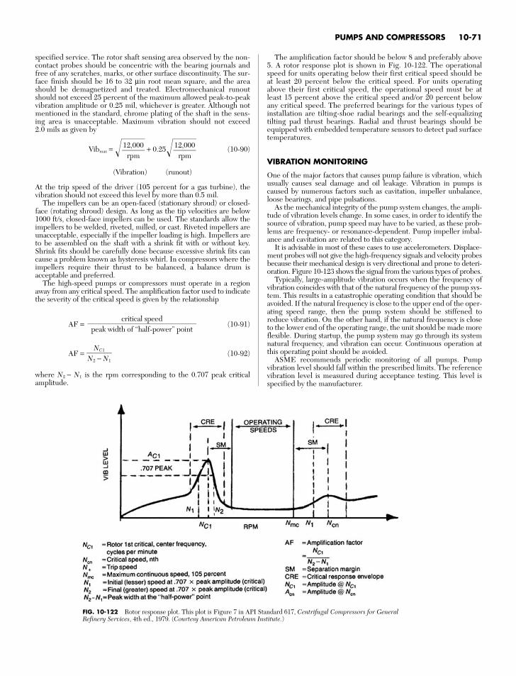
specified service. The rotor shaft sensing area observed by the non-contact probes should be concentric with the bearing journals andfree of any scratches, marks, or other surface discontinuity. The sur-face finish should be 16 to 32 µin root mean square, and the areashould be demagnetized and treated. Electromechanical runoutshould not exceed 25 percent of the maximum allowed peak-to-peakvibration amplitude or 0.25 mil, whichever is greater. Although notmentioned in the standard, chrome plating of the shaft in the sens-ing area is unacceptable. Maximum vibration should not exceed2.0 mils as given by
Vibmax = + 0.25 (10-90)
(Vibration) (runout)
At the trip speed of the driver (105 percent for a gas turbine), thevibration should not exceed this level by more than 0.5 mil.
The impellers can be an open-faced (stationary shroud) or closed-face (rotating shroud) design. As long as the tip velocities are below1000 ft/s, closed-face impellers can be used. The standards allow theimpellers to be welded, riveted, milled, or cast. Riveted impellers areunacceptable, especially if the impeller loading is high. Impellers areto be assembled on the shaft with a shrink fit with or without key.Shrink fits should be carefully done because excessive shrink fits cancause a problem known as hysteresis whirl. In compressors where theimpellers require their thrust to be balanced, a balance drum isacceptable and preferred.
The high-speed pumps or compressors must operate in a regionaway from any critical speed. The amplification factor used to indicatethe severity of the critical speed is given by the relationship
AF = (10-91)
AF = (10-92)
where N2 − N1 is the rpm corresponding to the 0.707 peak criticalamplitude.
NC1N2 − N1
critical speedpeak width of “half-power” point
12,000
rpm12,000
rpm
The amplification factor should be below 8 and preferably above5. A rotor response plot is shown in Fig. 10-122. The operationalspeed for units operating below their first critical speed should beat least 20 percent below the critical speed. For units operatingabove their first critical speed, the operational speed must be atleast 15 percent above the critical speed and/or 20 percent belowany critical speed. The preferred bearings for the various types ofinstallation are tilting-shoe radial bearings and the self-equalizingtilting pad thrust bearings. Radial and thrust bearings should beequipped with embedded temperature sensors to detect pad surfacetemperatures.
VIBRATION MONITORING
One of the major factors that causes pump failure is vibration, whichusually causes seal damage and oil leakage. Vibration in pumps iscaused by numerous factors such as cavitation, impeller unbalance,loose bearings, and pipe pulsations.
As the mechanical integrity of the pump system changes, the ampli-tude of vibration levels change. In some cases, in order to identify thesource of vibration, pump speed may have to be varied, as these prob-lems are frequency- or resonance-dependent. Pump impeller imbal-ance and cavitation are related to this category.
It is advisable in most of these cases to use accelerometers. Displace-ment probes will not give the high-frequency signals and velocity probesbecause their mechanical design is very directional and prone to deteri-oration. Figure 10-123 shows the signal from the various types of probes.
Typically, large-amplitude vibration occurs when the frequency ofvibration coincides with that of the natural frequency of the pump sys-tem. This results in a catastrophic operating condition that should beavoided. If the natural frequency is close to the upper end of the oper-ating speed range, then the pump system should be stiffened toreduce vibration. On the other hand, if the natural frequency is closeto the lower end of the operating range, the unit should be made moreflexible. During startup, the pump system may go through its systemnatural frequency, and vibration can occur. Continuous operation atthis operating point should be avoided.
ASME recommends periodic monitoring of all pumps. Pumpvibration level should fall within the prescribed limits. The referencevibration level is measured during acceptance testing. This level isspecified by the manufacturer.
PUMPS AND COMPRESSORS 10-71
FIG. 10-122 Rotor response plot. This plot is Figure 7 in API Standard 617, Centrifugal Compressors for GeneralRefinery Services, 4th ed., 1979. (Courtesy American Petroleum Institute.)
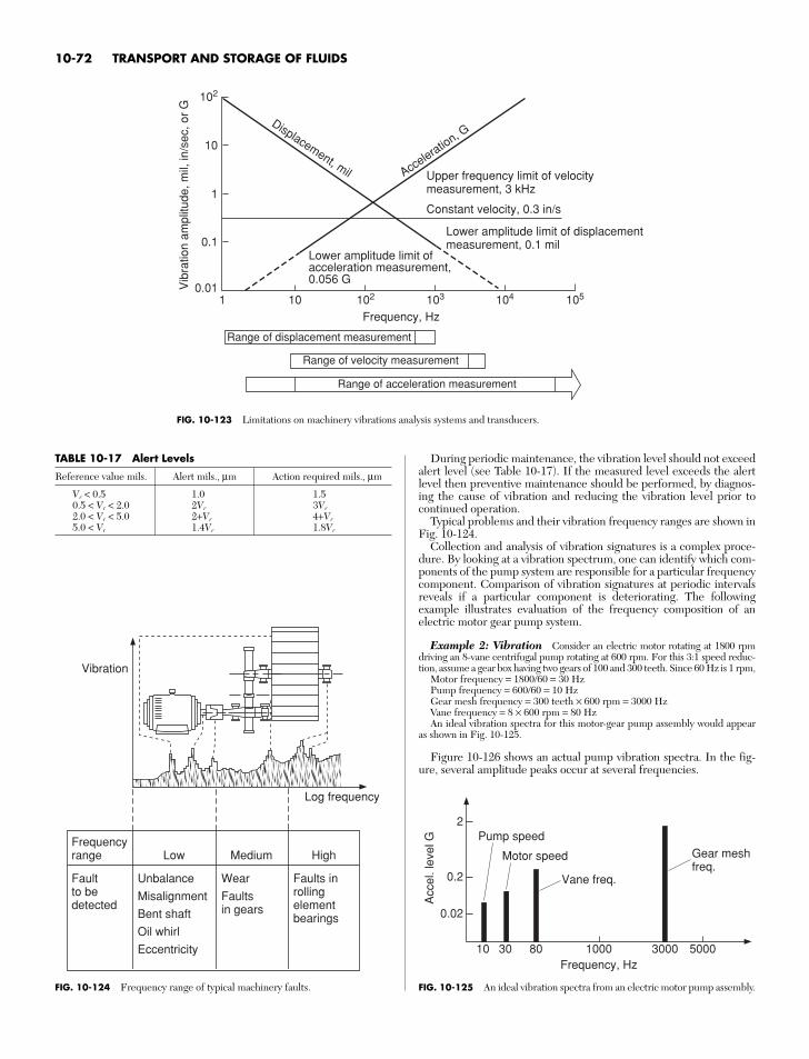
During periodic maintenance, the vibration level should not exceedalert level (see Table 10-17). If the measured level exceeds the alertlevel then preventive maintenance should be performed, by diagnos-ing the cause of vibration and reducing the vibration level prior tocontinued operation.
Typical problems and their vibration frequency ranges are shown inFig. 10-124.
Collection and analysis of vibration signatures is a complex proce-dure. By looking at a vibration spectrum, one can identify which com-ponents of the pump system are responsible for a particular frequencycomponent. Comparison of vibration signatures at periodic intervalsreveals if a particular component is deteriorating. The followingexample illustrates evaluation of the frequency composition of anelectric motor gear pump system.
Example 2: Vibration Consider an electric motor rotating at 1800 rpmdriving an 8-vane centrifugal pump rotating at 600 rpm. For this 3:1 speed reduc-tion, assume a gear box having two gears of 100 and 300 teeth. Since 60 Hz is 1 rpm,
Motor frequency = 1800/60 = 30 HzPump frequency = 600/60 = 10 HzGear mesh frequency = 300 teeth × 600 rpm = 3000 HzVane frequency = 8 × 600 rpm = 80 HzAn ideal vibration spectra for this motor-gear pump assembly would appear
as shown in Fig. 10-125.
Figure 10-126 shows an actual pump vibration spectra. In the fig-ure, several amplitude peaks occur at several frequencies.
10-72 TRANSPORT AND STORAGE OF FLUIDS
10
102
102 103 104 105
1
0.1
Vib
ratio
n am
plitu
de, m
il, in
/sec
, or
G
0.011 10
Frequency, Hz
Upper frequency limit of velocitymeasurement, 3 kHz
Constant velocity, 0.3 in/s
Lower amplitude limit of displacementmeasurement, 0.1 mil
Lower amplitude limit ofacceleration measurement,0.056 G
Acceleratio
n, GDisplacement, mil
Range of acceleration measurement
Range of velocity measurement
Range of displacement measurement
FIG. 10-123 Limitations on machinery vibrations analysis systems and transducers.
TABLE 10-17 Alert Levels
Reference value mils. Alert mils., µm Action required mils., µm
Vr < 0.5 1.0 1.50.5 < Vr < 2.0 2Vr 3Vr
2.0 < Vr < 5.0 2+Vr 4+Vr
5.0 < Vr 1.4Vr 1.8Vr
Vibration
Log frequency
Frequencyrange Low
Faultto bedetected
Unbalance
Misalignment
Bent shaft
Oil whirl
Eccentricity
Medium High
Wear
Faultsin gears
Faults inrollingelementbearings
FIG. 10-124 Frequency range of typical machinery faults.
2
0.2
Acc
el. l
evel
G
0.02
10 30 80 1000Frequency, Hz
3000 5000
Pump speed
Motor speed
Vane freq.
Gear meshfreq.
FIG. 10-125 An ideal vibration spectra from an electric motor pump assembly.
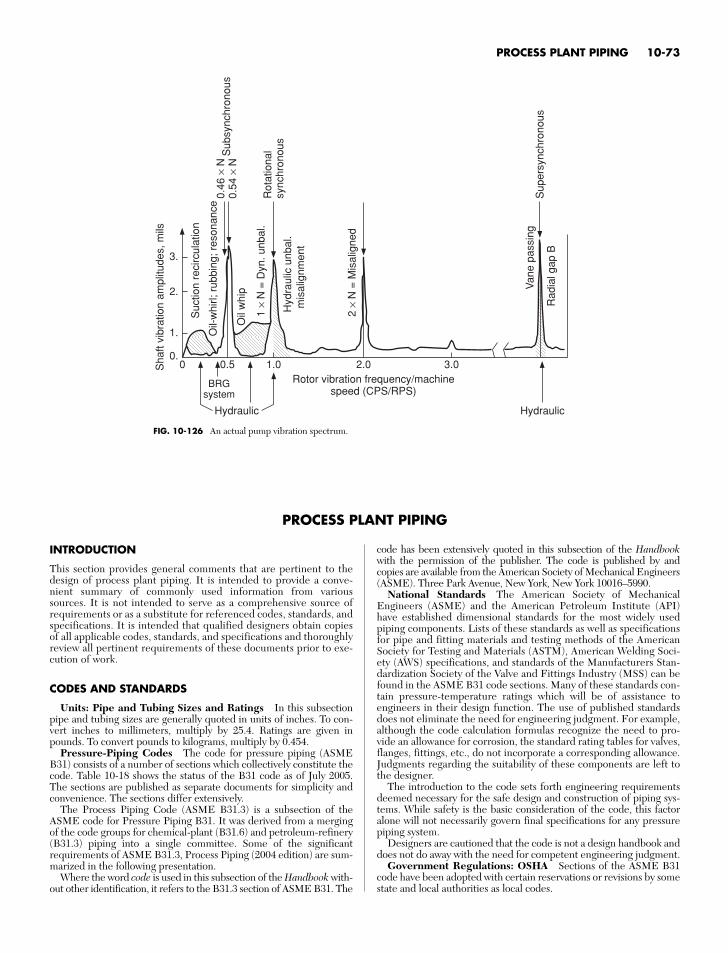
INTRODUCTION
This section provides general comments that are pertinent to thedesign of process plant piping. It is intended to provide a conve-nient summary of commonly used information from varioussources. It is not intended to serve as a comprehensive source ofrequirements or as a substitute for referenced codes, standards, andspecifications. It is intended that qualified designers obtain copiesof all applicable codes, standards, and specifications and thoroughlyreview all pertinent requirements of these documents prior to exe-cution of work.
CODES AND STANDARDS
Units: Pipe and Tubing Sizes and Ratings In this subsectionpipe and tubing sizes are generally quoted in units of inches. To con-vert inches to millimeters, multiply by 25.4. Ratings are given inpounds. To convert pounds to kilograms, multiply by 0.454.
Pressure-Piping Codes The code for pressure piping (ASMEB31) consists of a number of sections which collectively constitute thecode. Table 10-18 shows the status of the B31 code as of July 2005.The sections are published as separate documents for simplicity andconvenience. The sections differ extensively.
The Process Piping Code (ASME B31.3) is a subsection of theASME code for Pressure Piping B31. It was derived from a mergingof the code groups for chemical-plant (B31.6) and petroleum-refinery(B31.3) piping into a single committee. Some of the significantrequirements of ASME B31.3, Process Piping (2004 edition) are sum-marized in the following presentation.
Where the word code is used in this subsection of the Handbook with-out other identification, it refers to the B31.3 section of ASME B31. The
code has been extensively quoted in this subsection of the Handbookwith the permission of the publisher. The code is published by andcopies are available from the American Society of Mechanical Engineers(ASME). Three Park Avenue, New York, New York 10016–5990.
National Standards The American Society of MechanicalEngineers (ASME) and the American Petroleum Institute (API)have established dimensional standards for the most widely usedpiping components. Lists of these standards as well as specificationsfor pipe and fitting materials and testing methods of the AmericanSociety for Testing and Materials (ASTM), American Welding Soci-ety (AWS) specifications, and standards of the Manufacturers Stan-dardization Society of the Valve and Fittings Industry (MSS) can befound in the ASME B31 code sections. Many of these standards con-tain pressure-temperature ratings which will be of assistance toengineers in their design function. The use of published standardsdoes not eliminate the need for engineering judgment. For example,although the code calculation formulas recognize the need to pro-vide an allowance for corrosion, the standard rating tables for valves,flanges, fittings, etc., do not incorporate a corresponding allowance.Judgments regarding the suitability of these components are left tothe designer.
The introduction to the code sets forth engineering requirementsdeemed necessary for the safe design and construction of piping sys-tems. While safety is the basic consideration of the code, this factoralone will not necessarily govern final specifications for any pressurepiping system.
Designers are cautioned that the code is not a design handbook anddoes not do away with the need for competent engineering judgment.
Government Regulations: OSHA Sections of the ASME B31code have been adopted with certain reservations or revisions by somestate and local authorities as local codes.
PROCESS PLANT PIPING 10-73
FIG. 10-126 An actual pump vibration spectrum.
3.
2.
Sha
ft vi
brat
ion
ampl
itude
s, m
ils
1.
0.0 0.5
BRGsystem
Hydraulic Hydraulic
1.0Rotor vibration frequency/machine
speed (CPS/RPS)
2.0 3.0
Suc
tion
reci
rcul
atio
n
Oil-
whi
rl; r
ubbi
ng; r
eson
ance
Oil
whi
p
1×
N =
Dyn
. unb
al.
2×
N =
Mis
alig
ned
Van
e pa
ssin
g
Rad
ial g
ap B
Sup
ersy
nchr
onou
s
Rot
atio
nal
sync
hron
ous
Sub
sync
hron
ous
0.46
× N
0.54
× N
Hyd
raul
ic u
nbal
.m
isal
ignm
ent
PROCESS PLANT PIPING
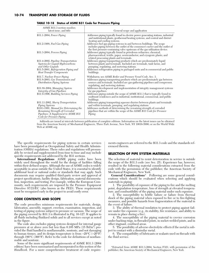
The specific requirements for piping systems in certain serviceshave been promulgated as Occupational Safety and Health Adminis-tration (OSHA) regulations. These rules and regulations will presum-ably be revised and supplemented from time to time and may includespecific requirements not addressed by the B31 sections.
International Regulations ASME piping codes have beenwidely used throughout the world for the design of facilities fallingwithin their defined scopes. Although the use of ASME codes is widelyacceptable in areas outside the United States, it is essential to identifyadditional local or national codes or standards that may apply. Suchdocuments may require qualified third-party review and approval ofproject specifications, facility design, fabrication, material documenta-tion, inspection, and testing. For example, within the European Com-munity, such requirements are imposed by the Pressure EquipmentDirective 97/23/EC (also known as the PED). These requirementsmust be recognized early in the project to avoid costly error.
CODE CONTENTS AND SCOPE
The code prescribes minimum requirements for materials, design,fabrication, assembly, support, erection, examination, inspection, andtesting of piping systems subject to pressure or vacuum. The scope ofthe piping covered by B31.3 is illustrated in Fig. 10-127. It applies toall fluids including fluidized solids and to all services except as notedin the figure.
The code also excludes piping systems designed for internal gaugepressures at or above zero but less than 0.105 MPa (15 lbf/in2) pro-vided the fluid handled is nonflammable, nontoxic, and not damagingto human tissues, and its design temperature is from −29°C (−20°F)through 186°C (366°F). Refer to the code for definitions of nonflam-mable and nontoxic.
Some of the more significant requirements of ASME B31.3 (2004edition) have been summarized and incorporated in this section of theHandbook. For a more comprehensive treatment of code require-
ments engineers are referred to the B31.3 code and the standards ref-erenced therein.
SELECTION OF PIPE SYSTEM MATERIALS
The selection of material to resist deterioration in service is outsidethe scope of the B31.3 code (see Sec. 25). Experience has, however,resulted in the following material considerations extracted from thecode with the permission of the publisher, the American Society ofMechanical Engineers, New York.
General Considerations* Following are some general consid-erations which should be evaluated when selecting and applyingmaterials in piping:
1. The possibility of exposure of the piping to fire and the meltingpoint, degradation temperature, loss of strength at elevated tempera-ture, and combustibility of the piping material under such exposure.
2. The susceptibility to brittle failure or failure from thermalshock of the piping material when exposed to fire or to fire-fightingmeasures, and possible hazards from fragmentation of the material inthe event of failure.
3. The ability of thermal insulation to protect piping against fail-ure under fire exposure (e.g., its stability, fire resistance, and ability toremain in place during a fire).
4. The susceptibility of the piping material to crevice corrosionunder backing rings, in threaded joints, in socket-welded joints, and inother stagnant, confined areas.
5. The possibility of adverse electrolytic effects if the metal is sub-ject to contact with a dissimilar metal.
6. The compatibility of lubricants or sealants used on threads withthe fluid service.
10-74 TRANSPORT AND STORAGE OF FLUIDS
TABLE 10-18 Status of ASME B31 Code for Pressure Piping
ASME B31.3 section number, latest issue, and title General scope and application
B31.1-2004, Power Piping Addresses piping typically found in electric power generating stations, industrial and institutional plants, geothermal heating systems, and central and districtheating and cooling systems.
B31.2-1968, Fuel Gas Piping Addresses fuel gas piping systems in and between buildings. The scope includes piping between the outlet of the consumer’s meter and the outlet ofthe first pressure-containing valve upstream of the gas utilization device.
B31.3-2004, Process Piping Addresses piping typically found in petroleum refineries; chemical, pharmaceutical, textile, paper, semiconductor, and cryogenic plants; andrelated processing plants and terminals.
B31.4-2002, Pipeline Transportation Addresses piping transporting products which are predominately liquid Systems for Liquid Hydrocarbons between plants and terminals. Included are terminals, tank farms, and and Other Liquids pumping, regulating, and metering stations.
B31.5-2001, Refrigeration Piping and Addresses refrigeration piping in packaged units and in commercial and public Heat Transfer Components buildings.
B31.7, Nuclear Power Piping Withdrawn; see ASME Boiler and Pressure Vessel Code, Sec. 3.B31.8-2003, Gas Transmission and Addresses piping transporting products which are predominately gas between Distribution Piping Systems sources and terminals. Included are gas-gathering pipelines and compressor,
regulating, and metering stations.B31.8S-2004, Managing System Addresses development and implementation of integrity management systems Integrity of Gas Pipelines for gas pipelines.
B31.9-1996, Building Services Piping Addresses piping outside the scope of ASME B31.1 that is typically found in multiunit residences and in industrial, institutional, commercial, and public buildings.
B31.11-2002, Slurry Transportation Addresses piping transporting aqueous slurries between plants and terminals Piping Systems and within terminals, pumping, and regulating stations.
B31G-1991, Manual for Determining the Addresses methods of determining the remaining strength of corroded Remaining Strength of Corroded pipelines that are within the scope of the ASME B31 Code for Pressure Pipelines: A Supplement to ASME B31 Piping.Code for Pressure Piping
Addenda are issued at intervals between publication of complete editions. Information on the latest issues can be obtainedfrom the American Society of Mechanical Engineers, Three Park Avenue, New York, NY 10016-5990; or on the World WideWeb at ASME.org.
*Extracted from ASME B31.3-2004, Section F323, with permission of thepublisher, the American Society of Mechanical Engineers, New York.
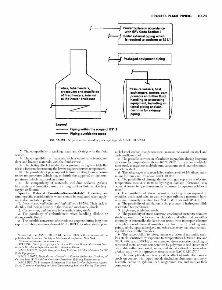
7. The compatibility of packing, seals, and O-rings with the fluidservice.
8. The compatibility of materials, such as cements, solvents, sol-ders, and brazing materials, with the fluid service.
9. The chilling effect of sudden loss of pressure on highly volatile flu-ids as a factor in determining the lowest expected service temperature.
10. The possibility of pipe support failure resulting from exposureto low temperatures (which may embrittle the supports) or high tem-peratures (which may weaken them).
11. The compatibility of materials, including sealants, gaskets,lubricants, and insulation, used in strong oxidizer fluid service (e.g.,oxygen or fluorine).
Specific Material Considerations—Metals* Following aresome specific considerations which should be evaluated when apply-ing certain metals in piping.
1. Irons—cast, malleable, and high silicon (14.5%). Their lack ofductility and their sensitivity to thermal and mechanical shock.
2. Carbon steel, and low and intermediate alloy steels.a. The possibility of embrittlement when handling alkaline or
strong caustic fluids.b. The possible conversion of carbides to graphite during long time
exposure to temperatures above 427°C (800°F) of carbon steels, plain
nickel steel, carbon-manganese steel, manganese-vanadium steel, andcarbon-silicon steel.
c. The possible conversion of carbides to graphite during long timeexposure to temperatures above 468°C (875°F) of carbon-molybde-num steel, manganese-molybdenum-vanadium steel, and chromium-vanadium steel.
d. The advantages of silicon-killed carbon steel (0.1% silicon mini-mum) for temperatures above 482°C (900°F).
e. The possibility of damage due to hydrogen exposure at elevatedtemperature (see API RP941); hydrogen damage (blistering) mayoccur at lower temperatures under exposure to aqueous acid solu-tions.†
f. The possibility of stress corrosion cracking when exposed tocyanides, acids, acid salts, or wet hydrogen sulfide; a maximum hard-ness limit is usually specified (see NACE MR0175 and RP0472).†
g. The possibility of sulfidation in the presence of hydrogen sulfideat elevated temperatures.
3. High-alloy (stainless) steels.a. The possibility of stress corrosion cracking of austenitic stainless
steels exposed to media such as chlorides and other halides eitherinternally or externally; the latter can result from improper selectionor application of thermal insulation, or from use of marking inks,paints, labels, tapes, adhesives, and other accessory materials contain-ing chlorides or other halides.
b. The susceptibility to intergranular corrosion of austenitic stain-less steels sensitized by exposure to temperatures between 427 and871°C (800 and 1600°F); as an example, stress corrosion cracking ofsensitized metal at room temperature by polythionic acid (reaction ofoxidizable sulfur compound, water, and air); stabilized or low-carbongrades may provide improved resistance (see NACE RP0170).†
c. The susceptibility to intercrystalline attack of austenitic stainlesssteels on contact with liquid metals (including aluminum, antimony,bismuth, cadmium, gallium, lead, magnesium, tin, and zinc) or theircompounds.
PROCESS PLANT PIPING 10-75
FIG. 10-127 Scope of work covered by process piping code ASME B31.3-2004.
*Extracted from ASME B31.3-2004, Section F323, with permission of thepublisher, the American Society of Mechanical Engineers, New York.
†Titles of referenced documents are:API RP941, Steels for Hydrogen Service at Elevated Temperatures and Pres-
sures in Petroleum Refineries and Petrochemical PlantsNACE MR0175, Sulfide Stress-Cracking Resistant Metallic Materials for Oil
Field EquipmentNACE RP0472, Methods and Controls to Prevent In-Service Cracking of
Carbon Steel (P-1) Welds in Corrosive Petroleum Refining EnvironmentsNACE RP0170, Protection of Austenitic Stainless Steel in Refineries Against
Stress Corrosion Cracking by Use of Neutralizing Solutions During Shutdown
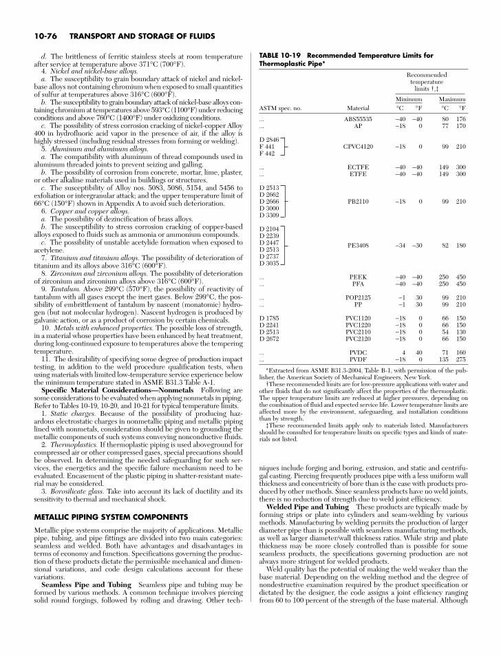
d. The brittleness of ferritic stainless steels at room temperatureafter service at temperature above 371°C (700°F).
4. Nickel and nickel-base alloys.a. The susceptibility to grain boundary attack of nickel and nickel-
base alloys not containing chromium when exposed to small quantitiesof sulfur at temperatures above 316°C (600°F).
b. The susceptibility to grain boundary attack of nickel-base alloys con-taining chromium at temperatures above 593°C (1100°F) under reducingconditions and above 760°C (1400°F) under oxidizing conditions.
c. The possibility of stress corrosion cracking of nickel-copper Alloy400 in hydrofluoric acid vapor in the presence of air, if the alloy ishighly stressed (including residual stresses from forming or welding).
5. Aluminum and aluminum alloys.a. The compatibility with aluminum of thread compounds used in
aluminum threaded joints to prevent seizing and galling.b. The possibility of corrosion from concrete, mortar, lime, plaster,
or other alkaline materials used in buildings or structures.c. The susceptibility of Alloy nos. 5083, 5086, 5154, and 5456 to
exfoliation or intergranular attack; and the upper temperature limit of66°C (150°F) shown in Appendix A to avoid such deterioration.
6. Copper and copper alloys.a. The possibility of dezincification of brass alloys.b. The susceptibility to stress corrosion cracking of copper-based
alloys exposed to fluids such as ammonia or ammonium compounds.c. The possibility of unstable acetylide formation when exposed to
acetylene.7. Titanium and titanium alloys. The possibility of deterioration of
titanium and its alloys above 316°C (600°F).8. Zirconium and zirconium alloys. The possibility of deterioration
of zirconium and zirconium alloys above 316°C (600°F).9. Tantalum. Above 299°C (570°F), the possibility of reactivity of
tantalum with all gases except the inert gases. Below 299°C, the pos-sibility of embrittlement of tantalum by nascent (monatomic) hydro-gen (but not molecular hydrogen). Nascent hydrogen is produced bygalvanic action, or as a product of corrosion by certain chemicals.
10. Metals with enhanced properties. The possible loss of strength,in a material whose properties have been enhanced by heat treatment,during long-continued exposure to temperatures above the temperingtemperature.
11. The desirability of specifying some degree of production impacttesting, in addition to the weld procedure qualification tests, whenusing materials with limited low-temperature service experience belowthe minimum temperature stated in ASME B31.3 Table A-1.
Specific Material Considerations—Nonmetals Following aresome considerations to be evaluated when applying nonmetals in piping.Refer to Tables 10-19, 10-20, and 10-21 for typical temperature limits.
1. Static charges. Because of the possibility of producing haz-ardous electrostatic charges in nonmetallic piping and metallic pipinglined with nonmetals, consideration should be given to grounding themetallic components of such systems conveying nonconductive fluids.
2. Thermoplastics. If thermoplastic piping is used aboveground forcompressed air or other compressed gases, special precautions shouldbe observed. In determining the needed safeguarding for such ser-vices, the energetics and the specific failure mechanism need to beevaluated. Encasement of the plastic piping in shatter-resistant mate-rial may be considered.
3. Borosilicate glass. Take into account its lack of ductility and itssensitivity to thermal and mechanical shock.
METALLIC PIPING SYSTEM COMPONENTS
Metallic pipe systems comprise the majority of applications. Metallicpipe, tubing, and pipe fittings are divided into two main categories:seamless and welded. Both have advantages and disadvantages interms of economy and function. Specifications governing the produc-tion of these products dictate the permissible mechanical and dimen-sional variations, and code design calculations account for thesevariations.
Seamless Pipe and Tubing Seamless pipe and tubing may beformed by various methods. A common technique involves piercingsolid round forgings, followed by rolling and drawing. Other tech-
niques include forging and boring, extrusion, and static and centrifu-gal casting. Piercing frequently produces pipe with a less uniform wallthickness and concentricity of bore than is the case with products pro-duced by other methods. Since seamless products have no weld joints,there is no reduction of strength due to weld joint efficiency.
Welded Pipe and Tubing These products are typically made byforming strips or plate into cylinders and seam-welding by variousmethods. Manufacturing by welding permits the production of largerdiameter pipe than is possible with seamless manufacturing methods,as well as larger diameter/wall thickness ratios. While strip and platethickness may be more closely controlled than is possible for someseamless products, the specifications governing production are notalways more stringent for welded products.
Weld quality has the potential of making the weld weaker than thebase material. Depending on the welding method and the degree ofnondestructive examination required by the product specification ordictated by the designer, the code assigns a joint efficiency rangingfrom 60 to 100 percent of the strength of the base material. Although
10-76 TRANSPORT AND STORAGE OF FLUIDS
TABLE 10-19 Recommended Temperature Limits forThermoplastic Pipe*
Recommendedtemperature
limits †,‡
Minimum MaximumASTM spec. no. Material °C °F °C °F
... ABS55535 −40 −40 80 176
... AP −18 0 77 170
D 2846F 441 CPVC4120 −18 0 99 210F 442
... ECTFE −40 −40 149 300
... ETFE −40 −40 149 300
D 2513D 2662D 2666 PB2110 −18 0 99 210D 3000D 3309
D 2104D 2239D 2447 PE3408 −34 −30 82 180D 2513D 2737D 3035
... PEEK −40 −40 250 450
... PFA −40 −40 250 450
... POP2125 −1 30 99 210
... PP −1 30 99 210
D 1785 PVC1120 −18 0 66 150D 2241 PVC1220 −18 0 66 150D 2513 PVC2110 −18 0 54 130D 2672 PVC2120 −18 0 66 150
... PVDC 4 40 71 160
... PVDF −18 0 135 275
*Extracted from ASME B31.3-2004, Table B-1, with permission of the pub-lisher, the American Society of Mechanical Engineers, New York.
†These recommended limits are for low-pressure applications with water andother fluids that do not significantly affect the properties of the thermoplastic.The upper temperature limits are reduced at higher pressures, depending onthe combination of fluid and expected service life. Lower temperature limits areaffected more by the environment, safeguarding, and installation conditionsthan by strength.
‡These recommended limits apply only to materials listed. Manufacturersshould be consulted for temperature limits on specific types and kinds of mate-rials not listed.
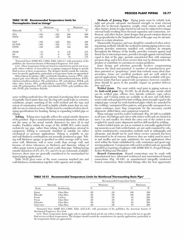
some welding methods have the potential of producing short sectionsof partially fused joints that may develop into small leaks in corrosiveconditions, proper matching of the weld method and the type andextent of examination will result in highly reliable joints that are suit-able for use in critical services. Welds must be considered when devel-oping specifications for bending, flaring or expanding welded pipe ortubing.
Tubing Tubing sizes typically reflect the actual outside diameterof the product. Pipe is manufactured to nominal diameters, which arenot the same as the actual outside diameters for sizes 12 in andsmaller. Facilities within the scope of the ASME B31 codes nearlyexclusively use pipe, rather than tubing, for applications external toequipment. Tubing is commonly classified as suitable for eithermechanical or pressure applications. Tubing is available in size and wall thickness combinations not normally produced as pipe. Tub-ing wall thickness (gauge) is specified as either average wall or mini-mum wall. Minimum wall is more costly than average wall, andbecause of closer tolerances on thickness and diameter, tubing ofeither gauge system is generally more costly than pipe. Tubing havingoutside diameters of 23⁄8, 27⁄8, 31⁄2, and 41⁄2 in are commonly available;however, these sizes are generally considered to be nonstandard fortypical piping applications.
Table 10-22 gives some of the more common standard size andwall-thickness combinations together with capacity and weight.
Methods of Joining Pipe Piping joints must be reliably leak-tight and provide adequate mechanical strength to resist externalloads due to thermal expansion, weight, wind, seismic activity, andother factors. Joints for pipe buried in soil may be subjected to uniqueexternal loads resulting from thermal expansion and contraction, set-tlement, and other factors. Joint designs that permit rotation about anaxis perpendicular to the longitudinal axis of the pipe may be advanta-geous in certain situations.
Disassembly frequency and ease should be considered when select-ing joining methods. Ideally the method for joining piping system com-ponents provides minimum installed cost, maintains its integritythroughout the lifetime of the facility, provides restraint against axialthrust due to internal pressure, provides strength against external loadsequal to that of the pipe, permits unrestricted flow with minimumpressure drop, and is free from crevices that may be detrimental to theproduct or contribute to corrosion or erosion problems.
Joint design and selection generally involves compromisingbetween the ideal and practical. A number of manufacturers pro-duce patented or “proprietary” joints that embody many ideal char-acteristics. Some are excellent products and are well suited tospecial applications. Valves and fittings are often available with pro-prietary joints that have gained wide acceptance; however, consider-ation should be given to the possible impact on product deliverytime and cost.
Welded Joints The most widely used joint in piping systems isthe butt-weld joint (Fig. 10-128). In all ductile pipe metals whichcan be welded, pipe, elbows, tees, laterals, reducers, caps, valves,flanges, and V-clamp joints are available in all sizes and wall thick-nesses with ends prepared for butt welding. Joint strength equal to theoriginal pipe (except for work-hardened pipes which are annealed bythe welding), unimpaired flow pattern, and generally unimpaired cor-rosion resistance more than compensate for the necessary carefulalignment, skilled labor, and equipment required.
Plain-end pipe used for socket-weld joints (Fig. 10-129) is availablein all sizes, but fittings and valves with socket-weld ends are limited tosizes 3 in and smaller, for which the extra cost of the socket is out-weighed by much easier alignment and less skill needed in welding.
Socket-welded joints are not as resistant to externally applied bend-ing moments as are butt-welded joints, are not easily examined by volu-metric nondestructive examination methods such as radiography andultrasonic, and should not be used where crevice corrosion has beendetermined to be of concern. However, they are widely used in sizes 2in and smaller and are quite satisfactory for most applications whenused within the limits established by code restrictions and good engi-neering judgment. Components with socket-welded ends are generallyspecified as requiring compliance with ASME B16.11, Forged-Fittings,Socket-Welding and Threaded.
Branch Connections Branch connections may be made withmanufactured tees, fabricated reinforced and nonreinforced branchconnections (Fig. 10-130), or manufactured integrally reinforcedbranch connections. Butt-welded fittings offer the best opportunity
PROCESS PLANT PIPING 10-77
TABLE 10-20 Recommended Temperature Limits forThermoplastics Used as Linings*
Minimum MaximumMaterials °C °F °C °F
PFA −198 −325 260 500PTFE −198 −325 260 500
FEP −198 −325 204 400ECTFE −198 −325 171 340ETFE −198 −325 149 300
PVDF −18 0 135 275PP −18 0 107 225PVDC −18 0 79 175
*Extracted from ASME B31.3-2004, Table A323.4.3, with permission of thepublisher, the American Society of Mechanical Engineers, New York.
NOTE: These temperature limits are based on material tests and do not neces-sarily reflect evidence of successful use as piping component linings in specificfluid services at these temperatures. The designer should consult the manufac-turer for specific applications, particularly as temperature limits are approached.
Abbreviations for plastics: ABS, acrylonitrile-butadiene-styrene; CPVC, chlo-rinated poly vinyl chloride; ECTFE, ethylene-chlorotrifluoroethylene; ETFE,ethylene-tetrafluoroethylene; PB, polybutylene; PE, polyethylene; PEEK, polyether ether ketone; PFA, perfluoroalkoxy copolymer; POP, poly phenyleneoxide; PP, polypropylene; PVC, poly vinyl chloride; PVDC, poly vinylidene chlo-ride; PVDF, poly vinylidene fluoride.
TABLE 10-21 Recommended Temperature Limits for Reinforced Thermosetting Resin Pipe*
Recommended temperature limits
Materials Minimum MaximumResin Reinforcing °C °F °C °F
Epoxy Glass fiber –29 –20 149 300Phenolic Glass fiber –29 –20 149 300Furan Carbon –29 –20 93 200Furan Glass fiber –29 –20 93 200Polyester Glass fiber –29 –20 93 200Vinyl ester Glass fiber –29 –20 93 200
*Extracted from ASME B31.3-2004, Table A323.4.2C, with permission of the publisher, the American Society ofMechanical Engineers, New York.
NOTE: These temperature limits apply only to materials listed and do not reflect evidence of successful use in specificfluid services at these temperatures. The designer should consult the manufacturer for specific applications, particularly asthe temperature limits are approached.
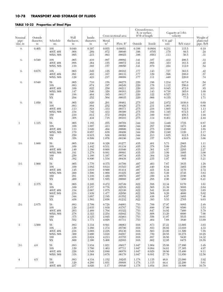
10-78 TRANSPORT AND STORAGE OF FLUIDS
TABLE 10-22 Properties of Steel Pipe
Circumference,ft, or surface, Capacity at 1-ft/s
Nominal Outside Wall InsideCross-sectional area ft2/ft of length velocity
Weight ofpipe diameter, Schedule thickness, diameter, Metal, U.S. gal/ plain-end
size, in in no. in in in2 Flow, ft2 Outside Inside min lb/h water pipe, lb/ft
f 0.405 10S 0.049 0.307 0.055 0.00051 0.106 0.0804 0.231 115.5 0.1940ST, 40S .068 .269 .072 .00040 .106 .0705 .179 89.5 .2480XS, 80S .095 .215 .093 .00025 .106 .0563 .113 56.5 .31
d 0.540 10S .065 .410 .097 .00092 .141 .107 .412 206.5 .3340ST, 40S .088 .364 .125 .00072 .141 .095 .323 161.5 .4280XS, 80S .119 .302 .157 .00050 .141 .079 .224 112.0 .54
r 0.675 10S .065 .545 .125 .00162 .177 .143 .727 363.5 .4240ST, 40S .091 .493 .167 .00133 .177 .129 .596 298.0 .5780XS, 80S .126 .423 .217 .00098 .177 .111 .440 220.0 .74
a 0.840 5S .065 .710 .158 .00275 .220 .186 1.234 617.0 .5410S .083 .674 .197 .00248 .220 .176 1.112 556.0 .6740ST, 40S .109 .622 .250 .00211 .220 .163 0.945 472.0 .8580XS, 80S .147 .546 .320 .00163 .220 .143 0.730 365.0 1.09160 .188 .464 .385 .00117 .220 .122 0.527 263.5 1.31XX .294 .252 .504 .00035 .220 .066 0.155 77.5 1.71
e 1.050 5S .065 .920 .201 .00461 .275 .241 2.072 1036.0 0.6910S .083 .884 .252 .00426 .275 .231 1.903 951.5 0.8640ST, 40S .113 .824 .333 .00371 .275 .216 1.665 832.5 1.1380XS, 80S .154 .742 .433 .00300 .275 .194 1.345 672.5 1.47160 .219 .612 .572 .00204 .275 .160 0.917 458.5 1.94XX .308 .434 .718 .00103 .275 .114 0.461 230.5 2.44
1 1.315 5S .065 1.185 .255 .00768 .344 .310 3.449 1725 0.8710S .109 1.097 .413 .00656 .344 .287 2.946 1473 1.4040ST, 40S .133 1.049 .494 .00600 .344 .275 2.690 1345 1.6880XS, 80S .179 0.957 .639 .00499 .344 .250 2.240 1120 2.17160 .250 0.815 .836 .00362 .344 .213 1.625 812.5 2.84XX .358 0.599 1.076 .00196 .344 .157 0.878 439.0 3.66
1d 1.660 5S .065 1.530 0.326 .01277 .435 .401 5.73 2865 1.1110S .109 1.442 0.531 .01134 .435 .378 5.09 2545 1.8140ST, 40S .140 1.380 0.668 .01040 .435 .361 4.57 2285 2.2780XS, 80S .191 1.278 0.881 .00891 .435 .335 3.99 1995 3.00160 .250 1.160 1.107 .00734 .435 .304 3.29 1645 3.76XX .382 0.896 1.534 .00438 .435 .235 1.97 985 5.21
1a 1.900 5S .065 1.770 0.375 .01709 .497 .463 7.67 3835 1.2810S .109 1.682 0.614 .01543 .497 .440 6.94 3465 2.0940ST, 40S .145 1.610 0.800 .01414 .497 .421 6.34 3170 2.7280XS, 80S .200 1.500 1.069 .01225 .497 .393 5.49 2745 3.63160 .281 1.338 1.429 .00976 .497 .350 4.38 2190 4.86XX .400 1.100 1.885 .00660 .497 .288 2.96 1480 6.41
2 2.375 5S .065 2.245 0.472 .02749 .622 .588 12.34 6170 1.6110S .109 2.157 0.776 .02538 .622 .565 11.39 5695 2.6440ST, 40S .154 2.067 1.075 .02330 .622 .541 10.45 5225 3.6580ST, 80S .218 1.939 1.477 .02050 .622 .508 9.20 4600 5.02160 .344 1.687 2.195 .01552 .622 .436 6.97 3485 7.46XX .436 1.503 2.656 .01232 .622 .393 5.53 2765 9.03
2a 2.875 5S .083 2.709 0.728 .04003 .753 .709 17.97 8985 2.4810S .120 2.635 1.039 .03787 .753 .690 17.00 8500 3.5340ST, 40S .203 2.469 1.704 .03322 .753 .647 14.92 7460 5.7980XS, 80S .276 2.323 2.254 .02942 .753 .608 13.20 6600 7.66160 .375 2.125 2.945 .02463 .753 .556 11.07 5535 10.01XX .552 1.771 4.028 .01711 .753 .464 7.68 3840 13.69
3 3.500 5S .083 3.334 0.891 .06063 .916 .873 27.21 13,605 3.0310S .120 3.260 1.274 .05796 .916 .853 26.02 13,010 4.3340ST, 40S .216 3.068 2.228 .05130 .916 .803 23.00 11,500 7.5880XS, 80S .300 2.900 3.016 .04587 .916 .759 20.55 10,275 10.25160 .438 2.624 4.213 .03755 .916 .687 16.86 8430 14.32XX .600 2.300 5.466 .02885 .916 .602 12.95 6475 18.58
3s 4.0 5S .083 3.834 1.021 .08017 1.047 1.004 35.98 17,990 3.4810S .120 3.760 1.463 .07711 1.047 0.984 34.61 17,305 4.9740ST, 40S .226 3.548 2.680 .06870 1.047 0.929 30.80 15,400 9.1180XS, 80S .318 3.364 3.678 .06170 1.047 0.881 27.70 13,850 12.50
4 4.5 5S .083 4.334 1.152 .10245 1.178 1.135 46.0 23,000 3.9210S .120 4.260 1.651 .09898 1.178 1.115 44.4 22,200 5.6140ST, 40S .237 4.026 3.17 .08840 1.178 1.054 39.6 19,800 10.79
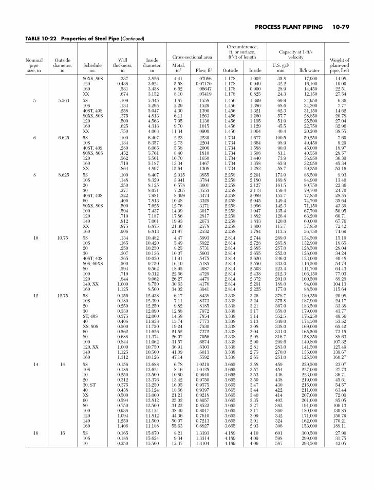
PROCESS PLANT PIPING 10-79
TABLE 10-22 Properties of Steel Pipe (Continued)
Circumference,ft, or surface, Capacity at 1-ft/s
Nominal Outside Wall InsideCross-sectional area ft2/ft of length velocity
Weight ofpipe diameter, Schedule thickness, diameter, Metal, U.S. gal/ plain-end
size, in in no. in in in2 Flow, ft2 Outside Inside min lb/h water pipe, lb/ft
80XS, 80S .337 3.826 4.41 .07986 1.178 1.002 35.8 17,900 14.98120 0.438 3.624 5.58 0.07170 1.178 0.949 32.2 16,100 19.00160 .531 3.438 6.62 .06647 1.178 0.900 28.9 14,450 22.51XX .674 3.152 8.10 .05419 1.178 0.825 24.3 12,150 27.54
5 5.563 5S .109 5.345 1.87 .1558 1.456 1.399 69.9 34,950 6.3610S .134 5.295 2.29 .1529 1.456 1.386 68.6 34,300 7.7740ST, 40S .258 5.047 4.30 .1390 1.456 1.321 62.3 31,150 14.6280XS, 80S .375 4.813 6.11 .1263 1.456 1.260 57.7 28,850 20.78120 .500 4.563 7.95 .1136 1.456 1.195 51.0 25,500 27.04160 .625 4.313 9.70 .1015 1.456 1.129 45.5 22,750 32.96XX .750 4.063 11.34 .0900 1.456 1.064 40.4 20,200 38.55
6 6.625 5S .109 6.407 2.23 .2239 1.734 1.677 100.5 50,250 7.6010S .134 6.357 2.73 .2204 1.734 1.664 98.9 49,450 9.2940ST, 40S .280 6.065 5.58 .2006 1.734 1.588 90.0 45,000 18.9780XS, 80S .432 5.761 8.40 .1810 1.734 1.508 81.1 40,550 28.57120 .562 5.501 10.70 .1650 1.734 1.440 73.9 36,950 36.39160 .719 5.187 13.34 .1467 1.734 1.358 65.9 32,950 45.34XX .864 4.897 15.64 .1308 1.734 1.282 58.7 29,350 53.16
8 8.625 5S .109 8.407 2.915 .3855 2.258 2.201 173.0 86,500 9.9310S .148 8.329 3.941 .3784 2.258 2.180 169.8 84,900 13.4020 .250 8.125 6.578 .3601 2.258 2.127 161.5 80,750 22.3630 .277 8.071 7.265 .3553 2.258 2.113 159.4 79,700 24.7040ST, 40S .322 7.981 8.399 .3474 2.258 2.089 155.7 77,850 28.5560 .406 7.813 10.48 .3329 2.258 2.045 149.4 74,700 35.6480XS, 80S .500 7.625 12.76 .3171 2.258 1.996 142.3 71,150 43.39100 .594 7.437 14.99 .3017 2.258 1.947 135.4 67,700 50.95120 .719 7.187 17.86 .2817 2.258 1.882 126.4 63,200 60.71140 .812 7.001 19.93 .2673 2.258 1.833 120.0 60,000 67.76XX .875 6.875 21.30 .2578 2.258 1.800 115.7 57,850 72.42160 .906 6.813 21.97 .2532 2.258 1.784 113.5 56,750 74.69
10 10.75 5S .134 10.482 4.47 .5993 2.814 2.744 269.0 134,500 15.1910S .165 10.420 5.49 .5922 2.814 2.728 265.8 132,900 18.6520 .250 10.250 8.25 .5731 2.814 2.685 257.0 128,500 28.0430 .307 10.136 10.07 .5603 2.814 2.655 252.0 126,000 34.2440ST, 40S .365 10.020 11.91 .5475 2.814 2.620 246.0 123,000 40.4880S, 60XS .500 9.750 16.10 .5185 2.814 2.550 233.0 116,500 54.7480 .594 9.562 18.95 .4987 2.814 2.503 223.4 111,700 64.43100 .719 9.312 22.66 .4729 2.814 2.438 212.3 106,150 77.03120 .844 9.062 26.27 .4479 2.814 2.372 201.0 100,500 89.29140, XX 1.000 8.750 30.63 .4176 2.814 2.291 188.0 94,000 104.13160 1.125 8.500 34.02 .3941 2.814 2.225 177.0 88,500 115.64
12 12.75 5S 0.156 12.438 6.17 .8438 3.338 3.26 378.7 189,350 20.9810S 0.180 12.390 7.11 .8373 3.338 3.24 375.8 187,900 24.1720 0.250 12.250 9.82 .8185 3.338 3.21 367.0 183,500 33.3830 0.330 12.090 12.88 .7972 3.338 3.17 358.0 179,000 43.77ST, 40S 0.375 12.000 14.58 .7854 3.338 3.14 352.5 176,250 49.5640 0.406 11.938 15.74 .7773 3.338 3.13 349.0 174,500 53.52XS, 80S 0.500 11.750 19.24 .7530 3.338 3.08 338.0 169,000 65.4260 0.562 11.626 21.52 .7372 3.338 3.04 331.0 165,500 73.1580 0.688 11.374 26.07 .7056 3.338 2.98 316.7 158,350 88.63100 0.844 11.062 31.57 .6674 3.338 2.90 299.6 149,800 107.32120, XX 1.000 10.750 36.91 .6303 3.338 2.81 283.0 141,500 125.49140 1.125 10.500 41.09 .6013 3.338 2.75 270.0 135,000 139.67160 1.312 10.126 47.14 .5592 3.338 2.65 251.0 125,500 160.27
14 14 5S 0.156 13.688 6.78 1.0219 3.665 3.58 459 229,500 23.0710S 0.188 13.624 8.16 1.0125 3.665 3.57 454 227,000 27.7310 0.250 13.500 10.80 0.9940 3.665 3.53 446 223,000 36.7120 0.312 13.376 13.42 0.9750 3.665 3.50 438 219,000 45.6130, ST 0.375 13.250 16.05 0.9575 3.665 3.47 430 215,000 54.5740 0.438 13.124 18.66 0.9397 3.665 3.44 422 211,000 63.44XS 0.500 13.000 21.21 0.9218 3.665 3.40 414 207,000 72.0960 0.594 12.812 25.02 0.8957 3.665 3.35 402 201,000 85.0580 0.750 12.500 31.22 0.8522 3.665 3.27 382 191,000 106.13100 0.938 12.124 38.49 0.8017 3.665 3.17 360 180,000 130.85120 1.094 11.812 44.36 0.7610 3.665 3.09 342 171,000 150.79140 1.250 11.500 50.07 0.7213 3.665 3.01 324 162,000 170.21160 1.406 11.188 55.63 0.6827 3.665 2.93 306 153,000 189.11
16 16 5S 0.165 15.670 8.21 1.3393 4.189 4.10 601 300,500 27.9010S 0.188 15.624 9.34 1.3314 4.189 4.09 598 299,000 31.7510 0.250 15.500 12.37 1.3104 4.189 4.06 587 293,500 42.05
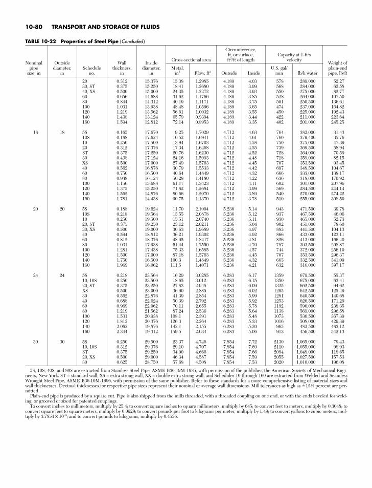
10-80 TRANSPORT AND STORAGE OF FLUIDS
TABLE 10-22 Properties of Steel Pipe (Concluded )
Circumference,ft, or surface, Capacity at 1-ft/s
Nominal Outside Wall InsideCross-sectional area ft2/ft of length velocity
Weight ofpipe diameter, Schedule thickness, diameter, Metal, U.S. gal/ plain-end
size, in in no. in in in2 Flow, ft2 Outside Inside min lb/h water pipe, lb/ft
20 0.312 15.376 15.38 1.2985 4.189 4.03 578 289,000 52.2730, ST 0.375 15.250 18.41 1.2680 4.189 3.99 568 284,000 62.5840, XS 0.500 15.000 24.35 1.2272 4.189 3.93 550 275,000 82.7760 0.656 14.688 31.62 1.1766 4.189 3.85 528 264,000 107.5080 0.844 14.312 40.19 1.1171 4.189 3.75 501 250,500 136.61100 1.031 13.938 48.48 1.0596 4.189 3.65 474 237,000 164.82120 1.219 13.562 56.61 1.0032 4.189 3.55 450 225,000 192.43140 1.438 13.124 65.79 0.9394 4.189 3.44 422 211,000 223.64160 1.594 12.812 72.14 0.8953 4.189 3.35 402 201,000 245.25
18 18 5S 0.165 17.670 9.25 1.7029 4.712 4.63 764 382,000 31.4310S 0.188 17.624 10.52 1.6941 4.712 4.61 760 379,400 35.7610 0.250 17.500 13.94 1.6703 4.712 4.58 750 375,000 47.3920 0.312 17.376 17.34 1.6468 4.712 4.55 739 369,500 58.94ST 0.375 17.250 20.76 1.6230 4.712 4.52 728 364,000 70.5930 0.438 17.124 24.16 1.5993 4.712 4.48 718 359,000 82.15XS 0.500 17.000 27.49 1.5763 4.712 4.45 707 353,500 93.4540 0.562 16.876 30.79 1.5533 4.712 4.42 697 348,500 104.6760 0.750 16.500 40.64 1.4849 4.712 4.32 666 333,000 138.1780 0.938 16.124 50.28 1.4180 4.712 4.22 636 318,000 170.92100 1.156 15.688 61.17 1.3423 4.712 4.11 602 301,000 207.96120 1.375 15.250 71.82 1.2684 4.712 3.99 569 284,500 244.14140 1.562 14.876 80.66 1.2070 4.712 3.89 540 270,000 274.22160 1.781 14.438 90.75 1.1370 4.712 3.78 510 255,000 308.50
20 20 5S 0.188 19.624 11.70 2.1004 5.236 5.14 943 471,500 39.7810S 0.218 19.564 13.55 2.0878 5.236 5.12 937 467,500 46.0610 0.250 19.500 15.51 2.0740 5.236 5.11 930 465,000 52.7320, ST 0.375 19.250 23.12 2.0211 5.236 5.04 902 451,000 78.6030, XS 0.500 19.000 30.63 1.9689 5.236 4.97 883 441,500 104.1340 0.594 18.812 36.21 1.9302 5.236 4.92 866 433,000 123.1160 0.812 18.376 48.95 1.8417 5.236 4.81 826 413,000 166.4080 1.031 17.938 61.44 1.7550 5.236 4.70 787 393,500 208.87100 1.281 17.438 75.33 1.6585 5.236 4.57 744 372,000 256.10120 1.500 17.000 87.18 1.5763 5.236 4.45 707 353,500 296.37140 1.750 16.500 100.3 1.4849 5.236 4.32 665 332,500 341.09160 1.969 16.062 111.5 1.4071 5.236 4.21 632 316,000 397.17
24 24 5S 0.218 23.564 16.29 3.0285 6.283 6.17 1359 679,500 55.3710, 10S 0.250 23.500 18.65 3.012 6.283 6.15 1350 675,000 63.4120, ST 0.375 23.250 27.83 2.948 6.283 6.09 1325 662,500 94.62XS 0.500 23.000 36.90 2.885 6.283 6.02 1295 642,500 125.4930 0.562 22.876 41.39 2.854 6.283 5.99 1281 640,500 140.6840 0.688 22.624 50.39 2.792 6.283 5.92 1253 626,500 171.2960 0.969 22.062 70.11 2.655 6.283 5.78 1192 596,000 238.3580 1.219 21.562 87.24 2.536 6.283 5.64 1138 569,000 296.58100 1.531 20.938 108.1 2.391 6.283 5.48 1073 536,500 367.39120 1.812 20.376 126.3 2.264 6.283 5.33 1016 508,000 429.39140 2.062 19.876 142.1 2.155 6.283 5.20 965 482,500 483.12160 2.344 19.312 159.5 2.034 6.283 5.06 913 456,500 542.13
30 30 5S 0.250 29.500 23.37 4.746 7.854 7.72 2130 1,065,000 79.4310, 10S 0.312 29.376 29.10 4.707 7.854 7.69 2110 1,055,000 98.93ST 0.375 29.250 34.90 4.666 7.854 7.66 2094 1,048,000 118.6520, XS 0.500 29.000 46.34 4.587 7.854 7.59 2055 1,027,500 157.5330 0.625 28.750 57.68 4.508 7.854 7.53 2020 1,010,000 196.08
5S, 10S, 40S, and 80S are extracted from Stainless Steel Pipe, ASME B36.19M-1985, with permission of the publisher, the American Society of Mechanical Engi-neers, New York. ST = standard wall, XS = extra strong wall, XX = double extra strong wall, and Schedules 10 through 160 are extracted from Welded and SeamlessWrought Steel Pipe, ASME B36.10M-1996, with permission of the same publisher. Refer to these standards for a more comprehensive listing of material sizes andwall thicknesses. Decimal thicknesses for respective pipe sizes represent their nominal or average wall dimensions. Mill tolerances as high as 12a percent are per-mitted.
Plain-end pipe is produced by a square cut. Pipe is also shipped from the mills threaded, with a threaded coupling on one end, or with the ends beveled for weld-ing, or grooved or sized for patented couplings.
To convert inches to millimeters, multiply by 25.4; to convert square inches to square millimeters, multiply by 645; to convert feet to meters, multiply by 0.3048; toconvert square feet to square meters, multiply by 0.0929; to convert pounds per foot to kilograms per meter, multiply by 1.49; to convert gallons to cubic meters, mul-tiply by 3.7854 × 10⁻³; and to convert pounds to kilograms, multiply by 0.4536.
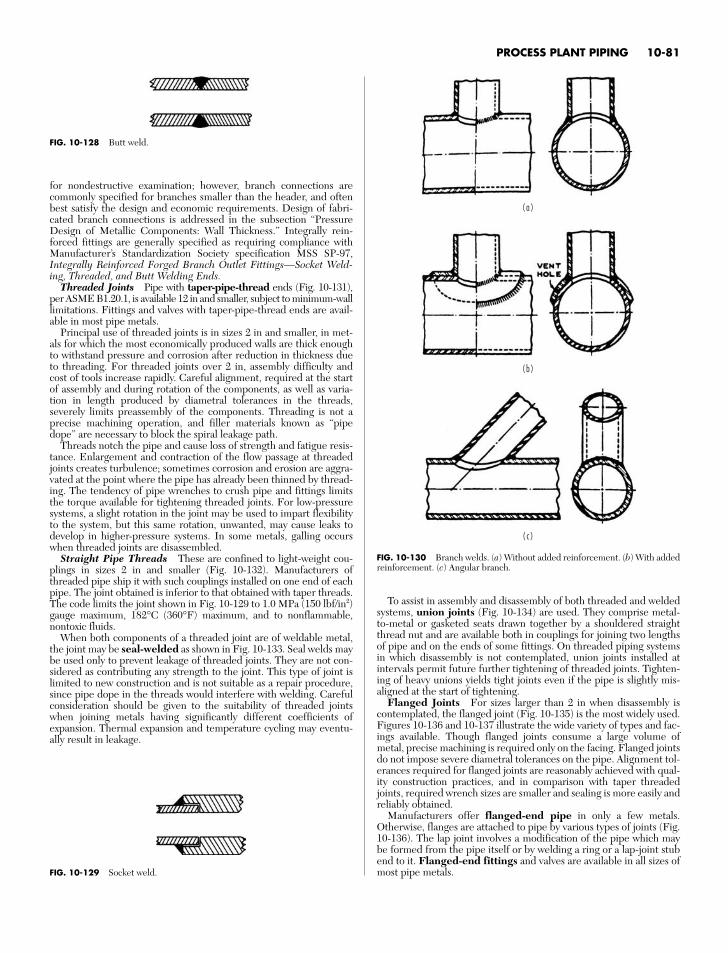
PROCESS PLANT PIPING 10-81
for nondestructive examination; however, branch connections arecommonly specified for branches smaller than the header, and oftenbest satisfy the design and economic requirements. Design of fabri-cated branch connections is addressed in the subsection “PressureDesign of Metallic Components: Wall Thickness.” Integrally rein-forced fittings are generally specified as requiring compliance withManufacturer’s Standardization Society specification MSS SP-97,Integrally Reinforced Forged Branch Outlet Fittings—Socket Weld-ing, Threaded, and Butt Welding Ends.
Threaded Joints Pipe with taper-pipe-thread ends (Fig. 10-131),per ASME B1.20.1, is available 12 in and smaller, subject to minimum-walllimitations. Fittings and valves with taper-pipe-thread ends are avail-able in most pipe metals.
Principal use of threaded joints is in sizes 2 in and smaller, in met-als for which the most economically produced walls are thick enoughto withstand pressure and corrosion after reduction in thickness dueto threading. For threaded joints over 2 in, assembly difficulty andcost of tools increase rapidly. Careful alignment, required at the startof assembly and during rotation of the components, as well as varia-tion in length produced by diametral tolerances in the threads,severely limits preassembly of the components. Threading is not aprecise machining operation, and filler materials known as “pipedope” are necessary to block the spiral leakage path.
Threads notch the pipe and cause loss of strength and fatigue resis-tance. Enlargement and contraction of the flow passage at threadedjoints creates turbulence; sometimes corrosion and erosion are aggra-vated at the point where the pipe has already been thinned by thread-ing. The tendency of pipe wrenches to crush pipe and fittings limitsthe torque available for tightening threaded joints. For low-pressuresystems, a slight rotation in the joint may be used to impart flexibilityto the system, but this same rotation, unwanted, may cause leaks todevelop in higher-pressure systems. In some metals, galling occurswhen threaded joints are disassembled.
Straight Pipe Threads These are confined to light-weight cou-plings in sizes 2 in and smaller (Fig. 10-132). Manufacturers ofthreaded pipe ship it with such couplings installed on one end of eachpipe. The joint obtained is inferior to that obtained with taper threads.The code limits the joint shown in Fig. 10-129 to 1.0 MPa (150 lbf/in2)gauge maximum, 182°C (360°F) maximum, and to nonflammable,nontoxic fluids.
When both components of a threaded joint are of weldable metal,the joint may be seal-welded as shown in Fig. 10-133. Seal welds maybe used only to prevent leakage of threaded joints. They are not con-sidered as contributing any strength to the joint. This type of joint islimited to new construction and is not suitable as a repair procedure,since pipe dope in the threads would interfere with welding. Carefulconsideration should be given to the suitability of threaded jointswhen joining metals having significantly different coefficients ofexpansion. Thermal expansion and temperature cycling may eventu-ally result in leakage.
To assist in assembly and disassembly of both threaded and weldedsystems, union joints (Fig. 10-134) are used. They comprise metal-to-metal or gasketed seats drawn together by a shouldered straightthread nut and are available both in couplings for joining two lengthsof pipe and on the ends of some fittings. On threaded piping systemsin which disassembly is not contemplated, union joints installed atintervals permit future further tightening of threaded joints. Tighten-ing of heavy unions yields tight joints even if the pipe is slightly mis-aligned at the start of tightening.
Flanged Joints For sizes larger than 2 in when disassembly iscontemplated, the flanged joint (Fig. 10-135) is the most widely used.Figures 10-136 and 10-137 illustrate the wide variety of types and fac-ings available. Though flanged joints consume a large volume ofmetal, precise machining is required only on the facing. Flanged jointsdo not impose severe diametral tolerances on the pipe. Alignment tol-erances required for flanged joints are reasonably achieved with qual-ity construction practices, and in comparison with taper threadedjoints, required wrench sizes are smaller and sealing is more easily andreliably obtained.
Manufacturers offer flanged-end pipe in only a few metals.Otherwise, flanges are attached to pipe by various types of joints (Fig.10-136). The lap joint involves a modification of the pipe which maybe formed from the pipe itself or by welding a ring or a lap-joint stubend to it. Flanged-end fittings and valves are available in all sizes ofmost pipe metals.
FIG. 10-128 Butt weld.
FIG. 10-129 Socket weld.
( a )
( b )
( c )
FIG. 10-130 Branch welds. (a) Without added reinforcement. (b) With addedreinforcement. (c) Angular branch.
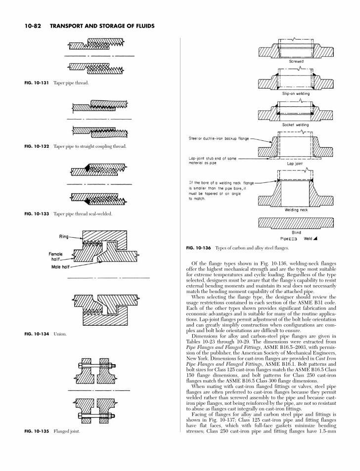
10-82 TRANSPORT AND STORAGE OF FLUIDS
FIG. 10-136 Types of carbon and alloy steel flanges.
FIG. 10-131 Taper pipe thread.
FIG. 10-132 Taper pipe to straight coupling thread.
FIG. 10-133 Taper pipe thread seal-welded.
FIG. 10-134 Union.
FIG. 10-135 Flanged joint.
Of the flange types shown in Fig. 10-136, welding-neck flangesoffer the highest mechanical strength and are the type most suitablefor extreme temperatures and cyclic loading. Regardless of the typeselected, designers must be aware that the flange’s capability to resistexternal bending moments and maintain its seal does not necessarilymatch the bending moment capability of the attached pipe.
When selecting the flange type, the designer should review theusage restrictions contained in each section of the ASME B31 code.Each of the other types shown provides significant fabrication andeconomic advantages and is suitable for many of the routine applica-tions. Lap-joint flanges permit adjustment of the bolt hole orientationand can greatly simplify construction when configurations are com-plex and bolt hole orientations are difficult to ensure.
Dimensions for alloy and carbon-steel pipe flanges are given inTables 10-23 through 10-29. The dimensions were extracted fromPipe Flanges and Flanged Fittings, ASME B16.5–2003, with permis-sion of the publisher, the American Society of Mechanical Engineers,New York. Dimensions for cast-iron flanges are provided in Cast IronPipe Flanges and Flanged Fittings, ASME B16.1. Bolt patterns andbolt sizes for Class 125 cast-iron flanges match the ASME B16.5 Class150 flange dimensions, and bolt patterns for Class 250 cast-ironflanges match the ASME B16.5 Class 300 flange dimensions.
When mating with cast-iron flanged fittings or valves, steel pipeflanges are often preferred to cast-iron flanges because they permitwelded rather than screwed assembly to the pipe and because cast-iron pipe flanges, not being reinforced by the pipe, are not so resistantto abuse as flanges cast integrally on cast-iron fittings.
Facing of flanges for alloy and carbon steel pipe and fittings isshown in Fig. 10-137; Class 125 cast-iron pipe and fitting flangeshave flat faces, which with full-face gaskets minimize bendingstresses; Class 250 cast-iron pipe and fitting flanges have 1.5-mm
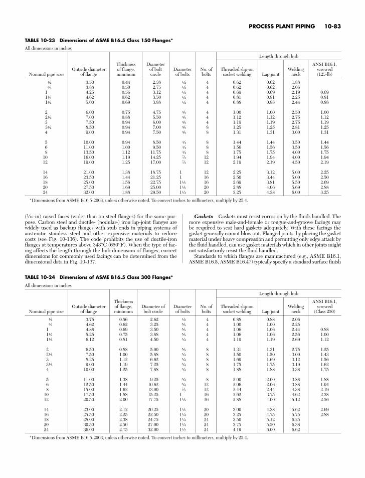
PROCESS PLANT PIPING 10-83
TABLE 10-23 Dimensions of ASME B16.5 Class 150 Flanges*
All dimensions in inches
Length through hub
Thickness Diameter ANSI B16.1,Outside diameter of flange, of bolt Diameter No. of Threaded slip-on Welding screwed
Nominal pipe size of flange minimum circle of bolts bolts socket welding Lap joint neck (125-lb)
a 3.50 0.44 2.38 a 4 0.62 0.62 1.88e 3.88 0.50 2.75 a 4 0.62 0.62 2.06
1 4.25 0.56 3.12 a 4 0.69 0.69 2.19 0.691d 4.62 0.62 3.50 a 4 0.81 0.81 2.25 0.811a 5.00 0.69 3.88 a 4 0.88 0.88 2.44 0.88
2 6.00 0.75 4.75 v 4 1.00 1.00 2.50 1.002a 7.00 0.88 5.50 v 4 1.12 1.12 2.75 1.123 7.50 0.94 6.00 v 4 1.19 1.19 2.75 1.193a 8.50 0.94 7.00 v 8 1.25 1.25 2.81 1.254 9.00 0.94 7.50 v 8 1.31 1.31 3.00 1.31
5 10.00 0.94 8.50 e 8 1.44 1.44 3.50 1.446 11.00 1.00 9.50 e 8 1.56 1.56 3.50 1.568 13.50 1.12 11.75 e 8 1.75 1.75 4.00 1.75
10 16.00 1.19 14.25 7⁄8 12 1.94 1.94 4.00 1.9412 19.00 1.25 17.00 7⁄8 12 2.19 2.19 4.50 2.19
14 21.00 1.38 18.75 1 12 2.25 3.12 5.00 2.2516 23.50 1.44 21.25 1 16 2.50 3.44 5.00 2.5018 25.00 1.56 22.75 1f 16 2.69 3.81 5.50 2.6920 27.50 1.69 25.00 1f 20 2.88 4.06 5.69 2.8824 32.00 1.88 29.50 1d 20 3.25 4.38 6.00 3.25
*Dimensions from ASME B16.5-2003, unless otherwise noted. To convert inches to millimeters, multiply by 25.4.
TABLE 10-24 Dimensions of ASME B16.5 Class 300 Flanges*
All dimensions in inches
Length through hub
Thickness ANSI B16.1,Outside diameter of flange, Diameter of Diameter No. of Threaded slip-on Welding screwed
Nominal pipe size of flange minimum bolt circle of bolts bolts socket welding Lap joint neck (Class 250)
a 3.75 0.56 2.62 a 4 0.88 0.88 2.06e 4.62 0.62 3.25 v 4 1.00 1.00 2.25
1 4.88 0.69 3.50 v 4 1.06 1.06 2.44 0.881d 5.25 0.75 3.88 v 4 1.06 1.06 2.56 1.001a 6.12 0.81 4.50 e 4 1.19 1.19 2.69 1.12
2 6.50 0.88 5.00 v 8 1.31 1.31 2.75 1.252a 7.50 1.00 5.88 e 8 1.50 1.50 3.00 1.433 8.25 1.12 6.62 e 8 1.69 1.69 3.12 1.563a 9.00 1.19 7.25 e 8 1.75 1.75 3.19 1.624 10.00 1.25 7.88 e 8 1.88 1.88 3.38 1.75
5 11.00 1.38 9.25 e 8 2.00 2.00 3.88 1.886 12.50 1.44 10.62 e 12 2.06 2.06 3.88 1.948 15.00 1.62 13.00 7⁄8 12 2.44 2.44 4.38 2.19
10 17.50 1.88 15.25 1 16 2.62 3.75 4.62 2.3812 20.50 2.00 17.75 1f 16 2.88 4.00 5.12 2.56
14 23.00 2.12 20.25 1f 20 3.00 4.38 5.62 2.6916 25.50 2.25 22.50 1d 20 3.25 4.75 5.75 2.8818 28.00 2.38 24.75 1d 24 3.50 5.12 6.2520 30.50 2.50 27.00 1d 24 3.75 5.50 6.3824 36.00 2.75 32.00 1a 24 4.19 6.00 6.62
*Dimensions from ASME B16.5-2003, unless otherwise noted. To convert inches to millimeters, multiply by 25.4.
(1⁄16-in) raised faces (wider than on steel flanges) for the same pur-pose. Carbon steel and ductile- (nodular-) iron lap-joint flanges arewidely used as backup flanges with stub ends in piping systems ofaustenitic stainless steel and other expensive materials to reducecosts (see Fig. 10-136). The code prohibits the use of ductile-ironflanges at temperatures above 343°C (650°F). When the type of fac-ing affects the length through the hub dimension of flanges, correctdimensions for commonly used facings can be determined from thedimensional data in Fig. 10-137.
Gaskets Gaskets must resist corrosion by the fluids handled. Themore expensive male-and-female or tongue-and-groove facings maybe required to seat hard gaskets adequately. With these facings thegasket generally cannot blow out. Flanged joints, by placing the gasketmaterial under heavy compression and permitting only edge attack bythe fluid handled, can use gasket materials which in other joints mightnot satisfactorily resist the fluid handled.
Standards to which flanges are manufactured (e.g., ASME B16.1,ASME B16.5, ASME B16.47) typically specify a standard surface finish
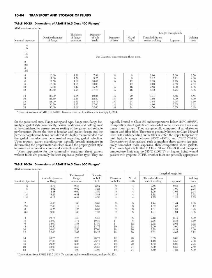
10-84 TRANSPORT AND STORAGE OF FLUIDS
for the gasket seal area. Flange rating and type, flange size, flange fac-ing type, gasket style, commodity, design conditions, and bolting mustall be considered to ensure proper seating of the gasket and reliableperformance. Unless the user is familiar with gasket design and theparticular application being considered, it is highly recommended thatthe gasket manufacturer be consulted regarding gasket selection.Upon request, gasket manufacturers typically provide assistance indetermining the proper material selection and the proper gasket styleto ensure an economical choice and a reliable system.
When appropriate for the commodity, elastomer sheet gasketswithout fillers are generally the least expensive gasket type. They are
typically limited to Class 150 and temperatures below 120°C (250°F).Composition sheet gaskets are somewhat more expensive than elas-tomer sheet gaskets. They are generally composed of an elastomerbinder with fiber filler. Their use is generally limited to Class 150 andClass 300, and depending on the filler selected the upper temperaturelimit typically ranges between 205°C (400°F) and 370°C (700°F).Nonelastomer sheet gaskets, such as graphite sheet gaskets, are gen-erally somewhat more expensive than composition sheet gaskets.Their use is typically limited to Class 150 and Class 300, and the uppertemperature limit may be 535°C (1000°F) or higher. Spiral-woundgaskets with graphite, PTFE, or other filler are generally appropriate
TABLE 10-26 Dimensions of ASME B16.5 Class 600 Flanges*
All dimensions in inches
Thickness of DiameterLength through hub
Outside diameter flange, of bolt Diameter No. of Threaded slip-on WeldingNominal pipe size of flange minimum circle of bolts bolts socket welding Lap joint neck
a 3.75 0.56 2.62 a 4 0.88 0.88 2.06e 4.62 0.62 3.25 v 4 1.00 1.00 2.25
1 4.88 0.69 3.50 v 4 1.06 1.06 2.441d 5.25 0.81 3.88 v 4 1.12 1.12 2.621a 6.12 0.88 4.50 e 4 1.25 1.25 2.75
2 6.50 1.00 5.00 v 8 1.44 1.44 2.882a 7.50 1.12 5.88 e 8 1.62 1.62 3.123 8.25 1.25 6.62 e 8 1.81 1.81 3.253a 9.00 1.38 7.25 7⁄8 8 1.94 1.94 3.38
4 10.75 1.50 8.50 7⁄8 8 2.12 2.12 4.005 13.00 1.75 10.50 1 8 2.38 2.38 4.506 14.00 1.88 11.50 1 12 2.62 2.62 4.628 16.50 2.19 13.75 1f 12 3.00 3.00 5.25
10 20.00 2.50 17.00 1d 16 3.38 4.38 6.0012 22.00 2.62 19.25 1d 20 3.62 4.62 6.12
14 23.75 2.75 20.75 1e 20 3.69 5.00 6.5016 27.00 3.00 23.75 1a 20 4.19 5.50 7.0018 29.25 3.25 25.75 1v 20 4.62 6.00 7.2520 32.00 3.50 28.50 1v 24 5.00 6.50 7.5024 37.00 4.00 33.00 17⁄8 24 5.50 7.25 8.00
*Dimensions from ASME B16.5-2003. To convert inches to millimeters, multiply by 25.4.
TABLE 10-25 Dimensions of ASME B16.5 Class 400 Flanges*
All dimensions in inches
Thickness DiameterLength through hub
Outside diameter of flange, of bolt Diameter No. of Threaded slip-on WeldingNominal pipe size of flange minimum circle of bolts bolts socket welding Lap joint neck
ae
11d1a Use Class 600 dimensions in these sizes.
22a33a
4 10.00 1.38 7.88 7⁄8 8 2.00 2.00 3.505 11.00 1.50 9.25 7⁄8 8 2.12 2.12 4.006 12.50 1.62 10.62 7⁄8 12 2.25 2.25 4.068 15.00 1.88 13.00 1 12 2.69 2.69 4.62
10 17.50 2.12 15.25 1d 16 2.88 4.00 4.8812 20.50 2.25 17.75 1d 16 3.12 4.25 5.38
14 23.00 2.38 20.25 1d 20 3.31 4.62 5.8816 25.50 2.50 22.50 1r 20 3.69 5.00 6.0018 28.00 2.62 24.75 1r 24 3.88 5.38 6.5020 30.50 2.75 27.00 1a 24 4.00 5.75 6.6224 36.00 3.00 32.00 1e 24 4.50 6.25 6.88
*Dimensions from ASME B16.5-2003. To convert inches to millimeters, multiply by 25.4.
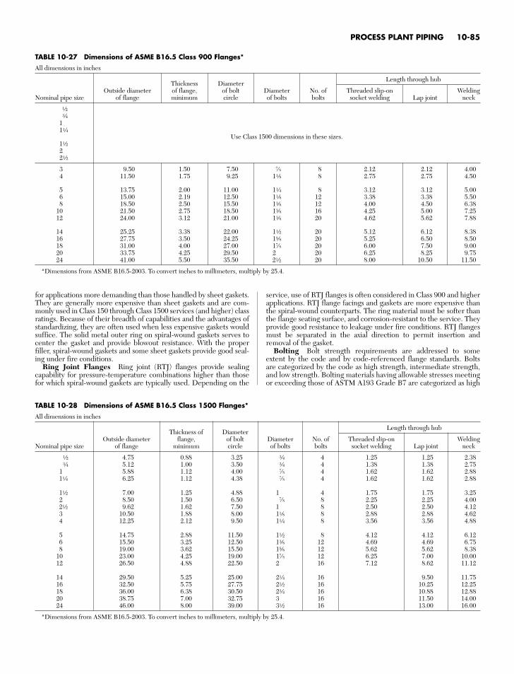
PROCESS PLANT PIPING 10-85
TABLE 10-27 Dimensions of ASME B16.5 Class 900 Flanges*
All dimensions in inches
Thickness DiameterLength through hub
Outside diameter of flange, of bolt Diameter No. of Threaded slip-on WeldingNominal pipe size of flange minimum circle of bolts bolts socket welding Lap joint neck
ae
11d
Use Class 1500 dimensions in these sizes.1a22a
3 9.50 1.50 7.50 7⁄8 8 2.12 2.12 4.004 11.50 1.75 9.25 1f 8 2.75 2.75 4.50
5 13.75 2.00 11.00 1d 8 3.12 3.12 5.006 15.00 2.19 12.50 1f 12 3.38 3.38 5.508 18.50 2.50 15.50 1r 12 4.00 4.50 6.38
10 21.50 2.75 18.50 1r 16 4.25 5.00 7.2512 24.00 3.12 21.00 1r 20 4.62 5.62 7.88
14 25.25 3.38 22.00 1a 20 5.12 6.12 8.3816 27.75 3.50 24.25 1v 20 5.25 6.50 8.5018 31.00 4.00 27.00 17⁄8 20 6.00 7.50 9.0020 33.75 4.25 29.50 2 20 6.25 8.25 9.7524 41.00 5.50 35.50 2a 20 8.00 10.50 11.50
*Dimensions from ASME B16.5-2003. To convert inches to millimeters, multiply by 25.4.
TABLE 10-28 Dimensions of ASME B16.5 Class 1500 Flanges*
All dimensions in inches
Thickness of DiameterLength through hub
Outside diameter flange, of bolt Diameter No. of Threaded slip-on WeldingNominal pipe size of flange minimum circle of bolts bolts socket welding Lap joint neck
a 4.75 0.88 3.25 e 4 1.25 1.25 2.38e 5.12 1.00 3.50 e 4 1.38 1.38 2.75
1 5.88 1.12 4.00 7⁄8 4 1.62 1.62 2.881d 6.25 1.12 4.38 7⁄8 4 1.62 1.62 2.88
1a 7.00 1.25 4.88 1 4 1.75 1.75 3.252 8.50 1.50 6.50 7⁄8 8 2.25 2.25 4.002a 9.62 1.62 7.50 1 8 2.50 2.50 4.123 10.50 1.88 8.00 1f 8 2.88 2.88 4.624 12.25 2.12 9.50 1d 8 3.56 3.56 4.88
5 14.75 2.88 11.50 1a 8 4.12 4.12 6.126 15.50 3.25 12.50 1r 12 4.69 4.69 6.758 19.00 3.62 15.50 1v 12 5.62 5.62 8.38
10 23.00 4.25 19.00 17⁄8 12 6.25 7.00 10.0012 26.50 4.88 22.50 2 16 7.12 8.62 11.12
14 29.50 5.25 25.00 2d 16 9.50 11.7516 32.50 5.75 27.75 2a 16 10.25 12.2518 36.00 6.38 30.50 2e 16 10.88 12.8820 38.75 7.00 32.75 3 16 11.50 14.0024 46.00 8.00 39.00 3a 16 13.00 16.00
*Dimensions from ASME B16.5-2003. To convert inches to millimeters, multiply by 25.4.
for applications more demanding than those handled by sheet gaskets.They are generally more expensive than sheet gaskets and are com-monly used in Class 150 through Class 1500 services (and higher) classratings. Because of their breadth of capabilities and the advantages ofstandardizing, they are often used when less expensive gaskets wouldsuffice. The solid metal outer ring on spiral-wound gaskets serves tocenter the gasket and provide blowout resistance. With the properfiller, spiral-wound gaskets and some sheet gaskets provide good seal-ing under fire conditions.
Ring Joint Flanges Ring joint (RTJ) flanges provide sealingcapability for pressure-temperature combinations higher than thosefor which spiral-wound gaskets are typically used. Depending on the
service, use of RTJ flanges is often considered in Class 900 and higherapplications. RTJ flange facings and gaskets are more expensive thanthe spiral-wound counterparts. The ring material must be softer thanthe flange seating surface, and corrosion-resistant to the service. Theyprovide good resistance to leakage under fire conditions. RTJ flangesmust be separated in the axial direction to permit insertion andremoval of the gasket.
Bolting Bolt strength requirements are addressed to someextent by the code and by code-referenced flange standards. Boltsare categorized by the code as high strength, intermediate strength,and low strength. Bolting materials having allowable stresses meetingor exceeding those of ASTM A193 Grade B7 are categorized as high
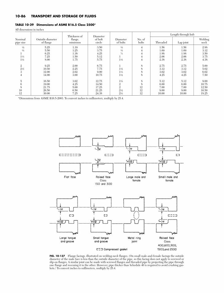
10-86 TRANSPORT AND STORAGE OF FLUIDS
FIG. 10-137 Flange facings, illustrated on welding-neck flanges. (On small male-and-female facings the outsidediameter of the male face is less than the outside diameter of the pipe, so this facing does not apply to screwed orslip-on flanges. A similar joint can be made with screwed flanges and threaded pipe by projecting the pipe throughone flange and recessing it in the other. However, pipe thicker than Schedule 40 is required to avoid crushing gas-kets.) To convert inches to millimeters, multiply by 25.4.
TABLE 10-29 Dimensions of ASME B16.5 Class 2500*
All dimensions in inches
Thickness of DiameterLength through hub
Nominal Outside diameter flange, of bolt Diameter No. of Weldingpipe size of flange minimum circle of bolts bolts Threaded Lap joint neck
a 5.25 1.19 3.50 e 4 1.56 1.56 2.88e 5.50 1.25 3.75 e 4 1.69 1.69 3.12
1 6.25 1.38 4.25 7⁄8 4 1.88 1.88 3.501d 7.25 1.50 5.12 1 4 2.06 2.06 3.751a 8.00 1.75 5.75 1f 4 2.38 2.38 4.38
2 9.25 2.00 6.75 1 8 2.75 2.75 5.002a 10.50 2.25 7.75 1f 8 3.12 3.12 5.623 12.00 2.62 9.00 1d 8 3.62 3.62 6.624 14.00 3.00 10.75 1a 8 4.25 4.25 7.50
5 16.50 3.62 12.75 1e 8 5.12 5.12 9.006 19.00 4.25 14.50 2 8 6.00 6.00 10.758 21.75 5.00 17.25 2 12 7.00 7.00 12.50
10 26.50 6.50 21.25 2a 12 9.00 9.00 16.5012 30.00 7.25 24.38 2e 12 10.00 10.00 18.25
*Dimensions from ASME B16.5-2003. To convert inches to millimeters, multiply by 25.4.
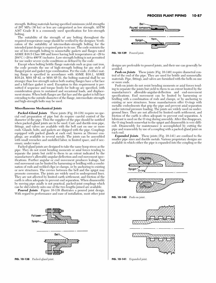
strength. Bolting materials having specified minimum yield strengthsof 207 MPa (30 ksi) or less are categorized as low strength. ASTMA307 Grade B is a commonly used specification for low-strengthbolting.
The suitability of the strength of any bolting throughout therequired temperature range should be verified by the designer. Verifi-cation of the suitability of intermediate-strength bolting for theintended joint design is required prior to its use. The code restricts theuse of low-strength bolting to nonmetallic gaskets and flanges ratedASME B16.5 Class 300 and lower having bolt temperatures at −29 to204°C (−20 to 400°F) inclusive. Low-strength bolting is not permittedfor use under severe cyclic conditions as defined by the code.
Except when bolting brittle flange materials such as gray cast iron,the code permits the use of high-strength bolting for any style offlanged joint and gasket type combination. Per the code, if either mat-ing flange is specified in accordance with ASME B16.1, ASMEB16.24, MSS SP-42, or MSS SP-51, the bolting material shall be nostronger than low-strength unless both mating flanges have a flat faceand a full-face gasket is used. Exception to this requirement is per-mitted if sequence and torque limits for bolt-up are specified, withconsideration given to sustained and occasional loads, and displace-ment strains. When both flanges are flat face and the gasket is full faceextending to the outside diameter of the flange, intermediate-strengthand high-strength bolts may be used.
Miscellaneous Mechanical JointsPacked-Gland Joints These joints (Fig. 10-138) require no spe-
cial end preparation of pipe but do require careful control of thediameter of the pipe. Thus the supplier of the pipe should be notifiedwhen packed-gland joints are to be used. Cast- and ductile-iron pipe,fittings, and valves are available with the bell cast on one or moreends. Glands, bolts, and gaskets are shipped with the pipe. Couplingsequipped with packed glands at each end, known as Dresser cou-plings, are available in several metals. The joints can be assembledwith small wrenches and unskilled labor, in limited space, and if nec-essary, under water.
Packed-gland joints are designed to take the same hoop stress as thepipe. They do not resist bending moments or axial forces tending toseparate the joints but yield to them to an extent indicated by themanufacturer’s allowable-angular-deflection and end movement spec-ifications. Further angular or end movement produces leakage, butend movement can be limited by harnessing or bridling with a combi-nation of rods and welded clips or clamps, or by anchoring to existingor new structures. The crevice between the bell and the spigot maypromote corrosion. The joints are widely used in underground lines.They are not affected by limited earth settlement, and friction of theearth is often adequate to prevent end separation. When disassemblyby moving pipe axially is not practical, packed-joint couplings whichcan be slid entirely onto one of the two lengths joined are available.
Poured Joints Figure 10-139 illustrates a poured joint design.With regard to performance and ease of installation, most other joint
designs are preferable to poured joints, and their use can generally beavoided.
Push-on Joints These joints (Fig. 10-140) require diametral con-trol of the end of the pipe. They are used for brittle and nonmetallicmaterials. Pipe, fittings, and valves are furnished with the bells on oneor more ends.
Push-on joints do not resist bending moments or axial forces tend-ing to separate the joints but yield to them to an extent limited by themanufacturer’s allowable-angular-deflection and end-movementspecifications. End movement can be limited by harnessing orbridling with a combination of rods and clamps, or by anchoring toexisting or new structures. Some manufacturers offer O-rings withmetallic embedments that grip the pipe and prevent axial separationunder internal pressure loading. The joints are widely used on under-ground lines. They are not affected by limited earth settlement, andfriction of the earth is often adequate to prevent end separation. Alubricant is used on the O ring during assembly. After this disappears,the O ring bonds somewhat to the spigot and disassembly is very diffi-cult. Disassembly for maintenance is accomplished by cutting thepipe and reassembly by use of a coupling with a packed-gland joint oneach end.
Expanded Joints These joints (Fig. 10-141) are confined to thesmaller pipe sizes and ductile metals. Various proprietary designs areavailable in which either the pipe is expanded into the coupling or the
PROCESS PLANT PIPING 10-87
FIG. 10-138 Packed-gland joint.
FIG. 10-139 Poured joint.
FIG. 10-140 Push-on joint.
FIG. 10-141 Expanded joint.
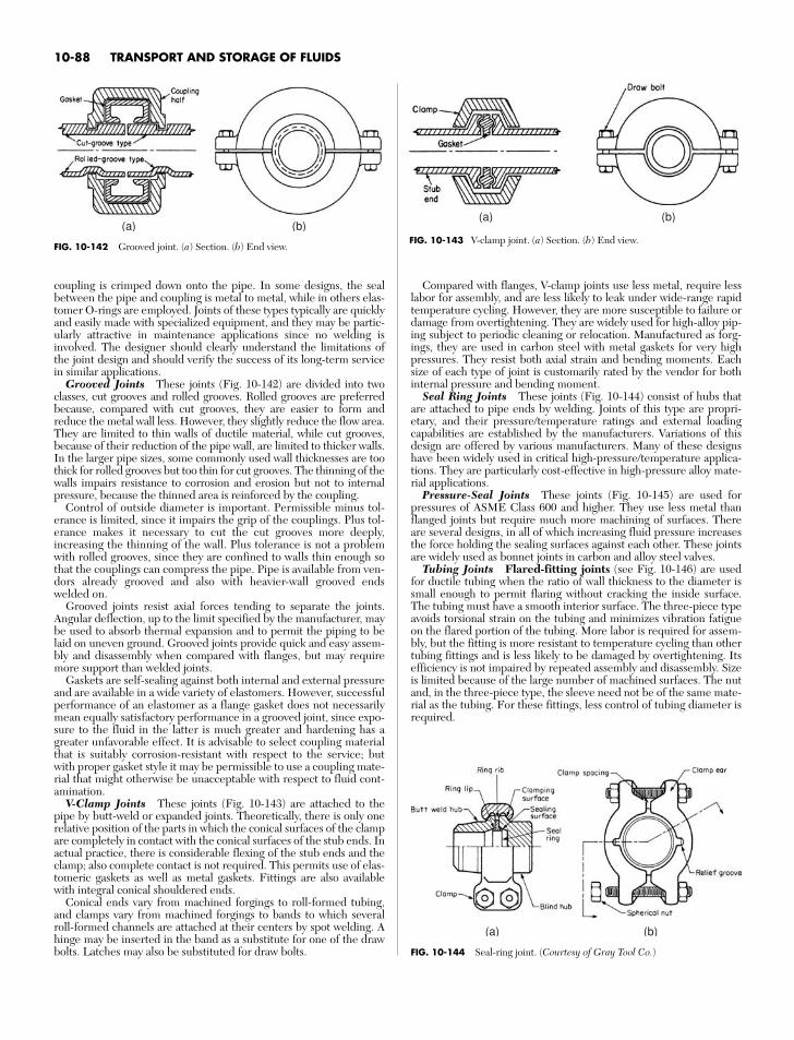
10-88 TRANSPORT AND STORAGE OF FLUIDS
FIG. 10-143 V-clamp joint. (a) Section. (b) End view.
(a) (b)
FIG. 10-144 Seal-ring joint. (Courtesy of Gray Tool Co.)
(a) (b)
coupling is crimped down onto the pipe. In some designs, the sealbetween the pipe and coupling is metal to metal, while in others elas-tomer O-rings are employed. Joints of these types typically are quicklyand easily made with specialized equipment, and they may be partic-ularly attractive in maintenance applications since no welding isinvolved. The designer should clearly understand the limitations ofthe joint design and should verify the success of its long-term servicein similar applications.
Grooved Joints These joints (Fig. 10-142) are divided into twoclasses, cut grooves and rolled grooves. Rolled grooves are preferredbecause, compared with cut grooves, they are easier to form andreduce the metal wall less. However, they slightly reduce the flow area.They are limited to thin walls of ductile material, while cut grooves,because of their reduction of the pipe wall, are limited to thicker walls.In the larger pipe sizes, some commonly used wall thicknesses are toothick for rolled grooves but too thin for cut grooves. The thinning of thewalls impairs resistance to corrosion and erosion but not to internalpressure, because the thinned area is reinforced by the coupling.
Control of outside diameter is important. Permissible minus tol-erance is limited, since it impairs the grip of the couplings. Plus tol-erance makes it necessary to cut the cut grooves more deeply,increasing the thinning of the wall. Plus tolerance is not a problemwith rolled grooves, since they are confined to walls thin enough sothat the couplings can compress the pipe. Pipe is available from ven-dors already grooved and also with heavier-wall grooved endswelded on.
Grooved joints resist axial forces tending to separate the joints.Angular deflection, up to the limit specified by the manufacturer, maybe used to absorb thermal expansion and to permit the piping to belaid on uneven ground. Grooved joints provide quick and easy assem-bly and disassembly when compared with flanges, but may requiremore support than welded joints.
Gaskets are self-sealing against both internal and external pressureand are available in a wide variety of elastomers. However, successfulperformance of an elastomer as a flange gasket does not necessarilymean equally satisfactory performance in a grooved joint, since expo-sure to the fluid in the latter is much greater and hardening has agreater unfavorable effect. It is advisable to select coupling materialthat is suitably corrosion-resistant with respect to the service; butwith proper gasket style it may be permissible to use a coupling mate-rial that might otherwise be unacceptable with respect to fluid cont-amination.
V-Clamp Joints These joints (Fig. 10-143) are attached to thepipe by butt-weld or expanded joints. Theoretically, there is only onerelative position of the parts in which the conical surfaces of the clampare completely in contact with the conical surfaces of the stub ends. Inactual practice, there is considerable flexing of the stub ends and theclamp; also complete contact is not required. This permits use of elas-tomeric gaskets as well as metal gaskets. Fittings are also availablewith integral conical shouldered ends.
Conical ends vary from machined forgings to roll-formed tubing,and clamps vary from machined forgings to bands to which severalroll-formed channels are attached at their centers by spot welding. Ahinge may be inserted in the band as a substitute for one of the drawbolts. Latches may also be substituted for draw bolts.
Compared with flanges, V-clamp joints use less metal, require lesslabor for assembly, and are less likely to leak under wide-range rapidtemperature cycling. However, they are more susceptible to failure ordamage from overtightening. They are widely used for high-alloy pip-ing subject to periodic cleaning or relocation. Manufactured as forg-ings, they are used in carbon steel with metal gaskets for very highpressures. They resist both axial strain and bending moments. Eachsize of each type of joint is customarily rated by the vendor for bothinternal pressure and bending moment.
Seal Ring Joints These joints (Fig. 10-144) consist of hubs thatare attached to pipe ends by welding. Joints of this type are propri-etary, and their pressure/temperature ratings and external loadingcapabilities are established by the manufacturers. Variations of thisdesign are offered by various manufacturers. Many of these designshave been widely used in critical high-pressure/temperature applica-tions. They are particularly cost-effective in high-pressure alloy mate-rial applications.
Pressure-Seal Joints These joints (Fig. 10-145) are used forpressures of ASME Class 600 and higher. They use less metal thanflanged joints but require much more machining of surfaces. Thereare several designs, in all of which increasing fluid pressure increasesthe force holding the sealing surfaces against each other. These jointsare widely used as bonnet joints in carbon and alloy steel valves.
Tubing Joints Flared-fitting joints (see Fig. 10-146) are usedfor ductile tubing when the ratio of wall thickness to the diameter issmall enough to permit flaring without cracking the inside surface.The tubing must have a smooth interior surface. The three-piece typeavoids torsional strain on the tubing and minimizes vibration fatigueon the flared portion of the tubing. More labor is required for assem-bly, but the fitting is more resistant to temperature cycling than othertubing fittings and is less likely to be damaged by overtightening. Itsefficiency is not impaired by repeated assembly and disassembly. Sizeis limited because of the large number of machined surfaces. The nutand, in the three-piece type, the sleeve need not be of the same mate-rial as the tubing. For these fittings, less control of tubing diameter isrequired.
FIG. 10-142 Grooved joint. (a) Section. (b) End view.
(a) (b)
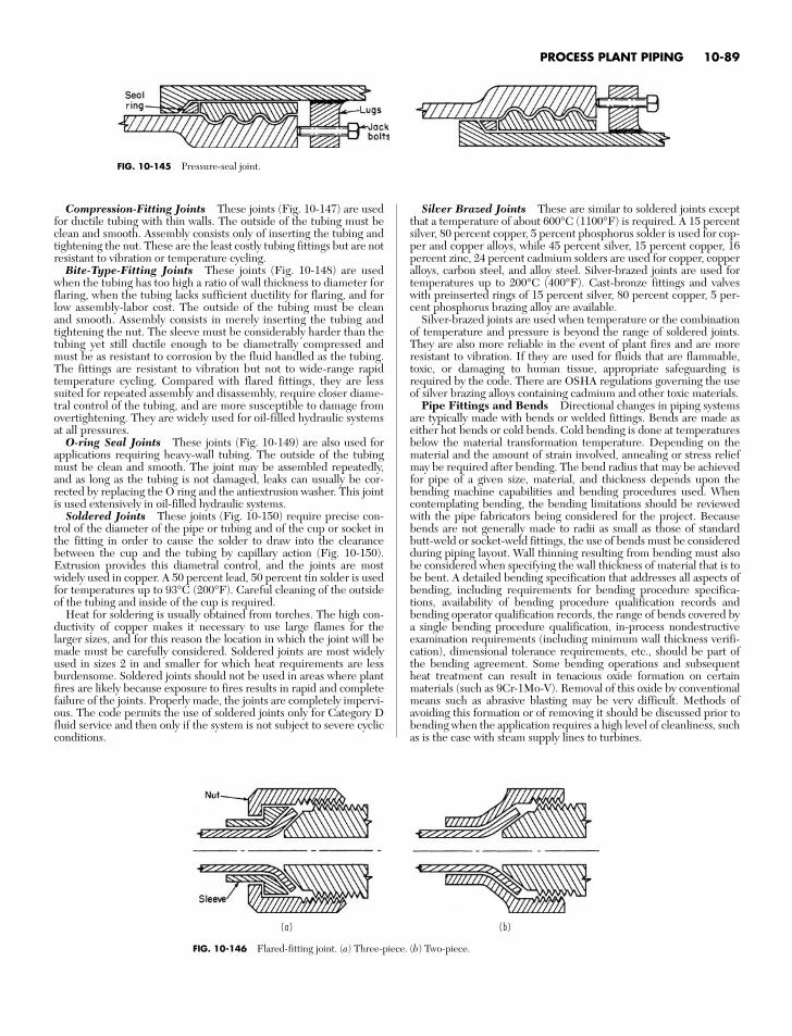
Compression-Fitting Joints These joints (Fig. 10-147) are usedfor ductile tubing with thin walls. The outside of the tubing must beclean and smooth. Assembly consists only of inserting the tubing andtightening the nut. These are the least costly tubing fittings but are notresistant to vibration or temperature cycling.
Bite-Type-Fitting Joints These joints (Fig. 10-148) are usedwhen the tubing has too high a ratio of wall thickness to diameter forflaring, when the tubing lacks sufficient ductility for flaring, and forlow assembly-labor cost. The outside of the tubing must be cleanand smooth. Assembly consists in merely inserting the tubing andtightening the nut. The sleeve must be considerably harder than thetubing yet still ductile enough to be diametrally compressed andmust be as resistant to corrosion by the fluid handled as the tubing.The fittings are resistant to vibration but not to wide-range rapidtemperature cycling. Compared with flared fittings, they are lesssuited for repeated assembly and disassembly, require closer diame-tral control of the tubing, and are more susceptible to damage fromovertightening. They are widely used for oil-filled hydraulic systemsat all pressures.
O-ring Seal Joints These joints (Fig. 10-149) are also used forapplications requiring heavy-wall tubing. The outside of the tubingmust be clean and smooth. The joint may be assembled repeatedly,and as long as the tubing is not damaged, leaks can usually be cor-rected by replacing the O ring and the antiextrusion washer. This jointis used extensively in oil-filled hydraulic systems.
Soldered Joints These joints (Fig. 10-150) require precise con-trol of the diameter of the pipe or tubing and of the cup or socket inthe fitting in order to cause the solder to draw into the clearancebetween the cup and the tubing by capillary action (Fig. 10-150).Extrusion provides this diametral control, and the joints are mostwidely used in copper. A 50 percent lead, 50 percent tin solder is usedfor temperatures up to 93°C (200°F). Careful cleaning of the outsideof the tubing and inside of the cup is required.
Heat for soldering is usually obtained from torches. The high con-ductivity of copper makes it necessary to use large flames for thelarger sizes, and for this reason the location in which the joint will bemade must be carefully considered. Soldered joints are most widelyused in sizes 2 in and smaller for which heat requirements are lessburdensome. Soldered joints should not be used in areas where plantfires are likely because exposure to fires results in rapid and completefailure of the joints. Properly made, the joints are completely impervi-ous. The code permits the use of soldered joints only for Category Dfluid service and then only if the system is not subject to severe cyclicconditions.
Silver Brazed Joints These are similar to soldered joints exceptthat a temperature of about 600°C (1100°F) is required. A 15 percentsilver, 80 percent copper, 5 percent phosphorus solder is used for cop-per and copper alloys, while 45 percent silver, 15 percent copper, 16percent zinc, 24 percent cadmium solders are used for copper, copperalloys, carbon steel, and alloy steel. Silver-brazed joints are used fortemperatures up to 200°C (400°F). Cast-bronze fittings and valveswith preinserted rings of 15 percent silver, 80 percent copper, 5 per-cent phosphorus brazing alloy are available.
Silver-brazed joints are used when temperature or the combinationof temperature and pressure is beyond the range of soldered joints.They are also more reliable in the event of plant fires and are moreresistant to vibration. If they are used for fluids that are flammable,toxic, or damaging to human tissue, appropriate safeguarding isrequired by the code. There are OSHA regulations governing the useof silver brazing alloys containing cadmium and other toxic materials.
Pipe Fittings and Bends Directional changes in piping systemsare typically made with bends or welded fittings. Bends are made aseither hot bends or cold bends. Cold bending is done at temperaturesbelow the material transformation temperature. Depending on thematerial and the amount of strain involved, annealing or stress reliefmay be required after bending. The bend radius that may be achievedfor pipe of a given size, material, and thickness depends upon thebending machine capabilities and bending procedures used. Whencontemplating bending, the bending limitations should be reviewedwith the pipe fabricators being considered for the project. Becausebends are not generally made to radii as small as those of standardbutt-weld or socket-weld fittings, the use of bends must be consideredduring piping layout. Wall thinning resulting from bending must alsobe considered when specifying the wall thickness of material that is tobe bent. A detailed bending specification that addresses all aspects ofbending, including requirements for bending procedure specifica-tions, availability of bending procedure qualification records andbending operator qualification records, the range of bends covered bya single bending procedure qualification, in-process nondestructiveexamination requirements (including minimum wall thickness verifi-cation), dimensional tolerance requirements, etc., should be part ofthe bending agreement. Some bending operations and subsequentheat treatment can result in tenacious oxide formation on certainmaterials (such as 9Cr-1Mo-V). Removal of this oxide by conventionalmeans such as abrasive blasting may be very difficult. Methods ofavoiding this formation or of removing it should be discussed prior tobending when the application requires a high level of cleanliness, suchas is the case with steam supply lines to turbines.
PROCESS PLANT PIPING 10-89
FIG. 10-145 Pressure-seal joint.
FIG. 10-146 Flared-fitting joint. (a) Three-piece. (b) Two-piece.
( a ) ( b )
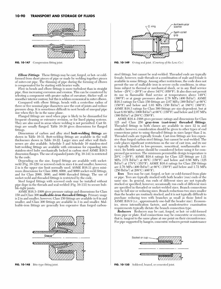
10-90 TRANSPORT AND STORAGE OF FLUIDS
FIG. 10-149 O-ring seal joint. (Courtesy of the Lenz Co.)
Socket or cup
FIG. 10-150 Soldered, brazed, or cemented joint.
Elbow Fittings These fittings may be cast, forged, or hot- or cold-formed from short pieces of pipe or made by welding together piecesof miter-cut pipe. The thinning of pipe during the forming of elbowsis compensated for by starting with heavier walls.
Flow in bends and elbow fittings is more turbulent than in straightpipe, thus increasing corrosion and erosion. This can be countered byselecting a component with greater radius of curvature, thicker wall, orsmoother interior contour, but this is seldom economical in miter elbows.
Compared with elbow fittings, bends with a centerline radius ofthree or five nominal pipe diameters save the cost of joints and reducepressure drop. It is sometimes difficult to nest bends of unequal pipesize when they lie in the same plane.
Flanged fittings are used when pipe is likely to be dismantled forfrequent cleaning or extensive revision, or for lined piping systems.They are also used in areas where welding is not permitted. Cast fit-tings are usually flanged. Table 10-30 gives dimensions for flangedfittings.
Dimensions of carbon and alloy steel butt-welding fittings areshown in Table 10-31. Butt-welding fittings are available in the wallthicknesses shown in Table 10-22. Larger sizes and other wall thick-nesses are also available. Schedule 5 and Schedule 10 stainless-steelbutt-welding fittings are available with extensions for expanding intostainless-steel hubs mechanically locked in carbon steel ASME B16.5dimension flanges. The use of expanded joints (Fig. 10-141) is restrictedby the code.
Depending on the size, forged fittings are available with socket-weld (Fig. 10-129) or screwed ends in sizes 4 in and smaller; however,2 in is the upper size limit normally used. ASME B16.11 gives mini-mum dimensions for Class 3000, 6000, and 9000 socket-weld fittings,and for Class 2000, 3000, and 6000 threaded fittings. The use ofsocket-weld and threaded fittings is restricted by the code.
Steel forged fittings with screwed ends may be installed withoutpipe dope in the threads and seal-welded (Fig. 10-133) to secure bub-ble-tight joints.
ASME B16.3–1998 gives pressure ratings and dimensions for Class150 and Class 300 malleable-iron threaded fittings. Primary usageis 2 in and smaller; however, Class 150 fittings are available in 6 in andsmaller, and Class 300 fittings are available in 3 in and smaller. Mal-leable-iron fittings are generally less expensive than forged carbon-
steel fittings, but cannot be seal-welded. Threaded ends are typicallyfemale; however, male threads or a combination of male and female isavailable in some fittings. Among other restrictions, the code does notpermit the use of malleable iron in severe cyclic conditions, in situa-tions subject to thermal or mechanical shock, or in any fluid servicebelow −29°C (−20°F) or above 343°C (650°F). It also does not permitits use in flammable fluid service at temperatures above 149°C(300°F) or at gauge pressures above 2.76 MPa (400 lbf/in2). ASMEB16.3 ratings for Class 150 fittings are 2.07 MPa (300 lbf/in2) at 66°C(150°F) and below and 1.03 MPa (150 lbf/in2) at 186°C (366°F).ASME B16.3 ratings for Class 300 fittings are size-dependent, but atleast 6.89 MPa (1000 lbf/in2) at 66°C (150°F) and below and 2.07 MPa(300 lbf/in2) at 288°C (550°F).
ASME B16.4–1998 gives pressure ratings and dimensions for Class125 and Class 250 gray-iron (cast-iron) threaded fittings.Threaded fittings in both classes are available in sizes 12 in andsmaller; however, consideration should be given to other types of endconnections prior to using threaded fittings in sizes larger than 2 in.Threaded ends are typically female. Cast-iron fittings are less expen-sive than forged carbon steel fittings, but cannot be seal-welded. Thecode places significant restrictions on the use of cast iron, and its useis typically limited to low-pressure, noncritical, nonflammable ser-vices. Its brittle nature should be considered before using it for com-pressed gas services. The minimum permissible design temperature is29°C (−20°F). ASME B16.4 ratings for Class 125 fittings are 1.21MPa (175 lbf/in2) at 66°C (150°F) and below and 0.86 MPa (125lbf/in2) at 178°C (353°F). ASME B16.4 ratings for Class 250 fittingsare 2.76 MPa (400 lbf/in2) at 66°C (150°F) and below and 1.72 MPa(250 lbf/in2) at 208°C (406°F).
Tees Tees may be cast, forged, or hot- or cold-formed from plateor pipe. Tees are typically stocked with both header (run) ends of thesame size. In general, run ends of different sizes are not typicallystocked or specified; however, occasionally run ends of different sizesare specified in threaded or socket-welded sizes. Branch connectionsmay be full size or reducing sizes. Branch reductions two sizes smallerthan the header are routinely stocked, and it is not typically difficult topurchase reducing tees with branches as small as those listed inASME B16.9 (i.e., approximately one-half the header size). Econom-ics, stress intensification factors, and nondestructive examinationrequirements typically dictate the branch connection type.
Reducers Reducers may be cast, forged, or hot- or cold-formedfrom pipe or plate. End connections may be concentric or eccentric,that is, tangent to the same plane at one point on their circumference.For pipe supported by hangers, concentric reducers permit maintenance
FIG. 10-147 Compression-fitting joint.
FIG. 10-148 Bite-type-fitting joint.
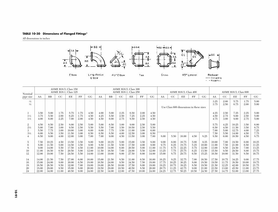
TABLE 10-30 Dimensions of Flanged Fittings*
All dimensions in inches
ASME B16.5, Class 150 ASME B16.5, Class 300
NominalASME B16.1, Class 125 ASME B16.1, Class 250 ASME B16.5, Class 400 ASME B16.5, Class 600
pipe size AA BB CC EE FF GG AA BB CC EE FF GG AA CC EE FF GG AA CC EE FF GG
a 3.25 2.00 5.75 1.75 5.00e 3.75 2.50 6.75 2.00 5.00
Use Class 600 dimensions in these sizes
1 3.50 5.00 1.75 5.75 1.75 4.50 4.00 5.00 2.25 6.50 2.00 4.50 4.25 2.50 7.25 2.25 5.001d 3.75 5.50 2.00 6.25 1.75 4.50 4.25 5.50 2.50 7.25 2.25 4.50 4.50 2.75 8.00 2.50 5.001a 4.00 6.00 2.25 7.00 2.00 4.50 4.50 6.00 2.75 8.50 2.50 4.50 4.75 3.00 9.00 2.75 5.00
2 4.50 6.50 2.50 8.00 2.50 5.00 5.00 6.50 3.00 9.00 2.50 5.00 5.75 4.25 10.25 3.50 6.002a 5.00 7.00 3.00 9.50 2.50 5.50 5.50 7.00 3.50 10.50 2.50 5.50 6.50 4.50 11.50 3.50 6.753 5.50 7.75 3.00 10.00 3.00 6.00 6.00 7.75 3.50 11.00 3.00 6.00 7.00 5.00 12.75 4.00 7.253a 6.00 8.50 3.50 11.50 3.00 6.50 6.50 8.50 4.00 12.50 3.00 6.50 7.50 5.50 14.00 4.50 7.754 6.50 9.00 4.00 12.00 3.00 7.00 7.00 9.00 4.50 13.50 3.00 7.00 8.00 5.50 16.00 4.50 8.25 8.50 6.00 16.50 4.50 8.75
5 7.50 10.25 4.50 13.50 3.50 8.00 8.00 10.25 5.00 15.00 3.50 8.00 9.00 6.00 16.75 5.00 9.25 10.00 7.00 19.50 6.00 10.256 8.00 11.50 5.00 14.50 3.50 9.00 8.50 11.50 5.50 17.50 4.00 9.00 9.75 6.25 18.75 5.25 10.00 11.00 7.50 21.00 6.50 11.258 9.00 14.00 5.50 17.50 4.50 11.00 10.00 14.00 6.00 20.50 5.00 11.00 11.75 6.75 22.25 5.75 12.00 13.00 8.50 24.50 7.00 13.25
10 11.00 16.50 6.50 20.50 5.00 12.00 11.50 16.50 7.00 24.00 5.50 12.00 13.25 7.75 25.75 6.25 13.50 15.50 9.50 29.50 8.00 15.7512 12.00 19.00 7.50 24.50 5.50 14.00 13.00 19.00 8.00 27.50 6.00 14.00 15.00 8.75 29.75 6.50 15.25 16.50 10.00 31.50 8.50 16.75
14 14.00 21.50 7.50 27.00 6.00 16.00 15.00 21.50 8.50 31.00 6.50 16.00 16.25 9.25 32.75 7.00 16.50 17.50 10.75 34.25 9.00 17.7516 15.00 24.00 8.00 30.00 6.50 18.00 16.50 24.00 9.50 34.50 7.50 18.00 17.75 10.25 36.25 8.00 18.50 19.50 11.75 38.50 10.00 19.7518 16.50 26.50 8.50 32.00 7.00 19.00 18.00 26.50 10.00 37.50 8.00 19.00 19.25 10.75 39.25 8.50 19.50 21.50 12.25 42.00 10.50 21.7520 18.00 29.00 9.50 35.00 8.00 20.00 19.50 29.00 10.50 40.50 8.50 20.00 20.75 11.25 42.75 9.00 21.00 23.50 13.00 45.50 11.00 23.7524 22.00 34.00 11.00 40.50 9.00 24.00 22.50 34.00 12.00 47.50 10.00 24.00 24.25 12.75 50.25 10.50 24.50 27.50 14.75 53.00 13.00 27.75
10
-91
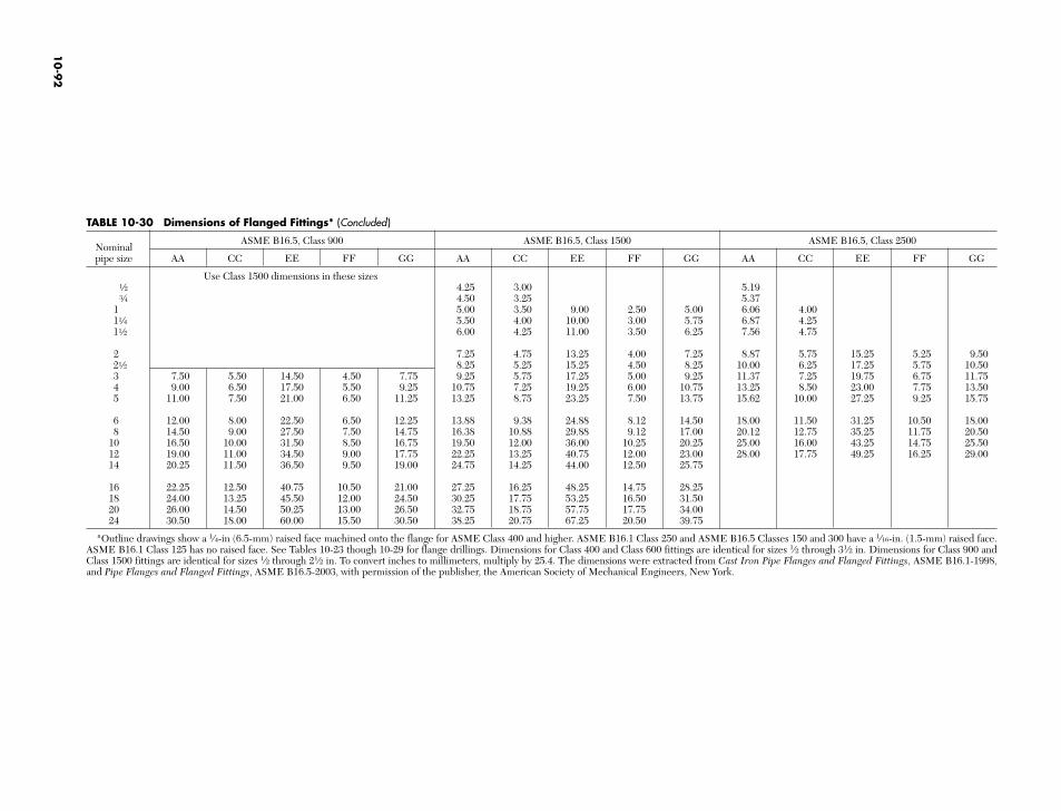
TABLE 10-30 Dimensions of Flanged Fittings* (Concluded)
NominalASME B16.5, Class 900 ASME B16.5, Class 1500 ASME B16.5, Class 2500
pipe size AA CC EE FF GG AA CC EE FF GG AA CC EE FF GG
Use Class 1500 dimensions in these sizesa 4.25 3.00 5.19e 4.50 3.25 5.37
1 5.00 3.50 9.00 2.50 5.00 6.06 4.001d 5.50 4.00 10.00 3.00 5.75 6.87 4.251a 6.00 4.25 11.00 3.50 6.25 7.56 4.75
2 7.25 4.75 13.25 4.00 7.25 8.87 5.75 15.25 5.25 9.502a 8.25 5.25 15.25 4.50 8.25 10.00 6.25 17.25 5.75 10.503 7.50 5.50 14.50 4.50 7.75 9.25 5.75 17.25 5.00 9.25 11.37 7.25 19.75 6.75 11.754 9.00 6.50 17.50 5.50 9.25 10.75 7.25 19.25 6.00 10.75 13.25 8.50 23.00 7.75 13.505 11.00 7.50 21.00 6.50 11.25 13.25 8.75 23.25 7.50 13.75 15.62 10.00 27.25 9.25 15.75
6 12.00 8.00 22.50 6.50 12.25 13.88 9.38 24.88 8.12 14.50 18.00 11.50 31.25 10.50 18.008 14.50 9.00 27.50 7.50 14.75 16.38 10.88 29.88 9.12 17.00 20.12 12.75 35.25 11.75 20.50
10 16.50 10.00 31.50 8.50 16.75 19.50 12.00 36.00 10.25 20.25 25.00 16.00 43.25 14.75 25.5012 19.00 11.00 34.50 9.00 17.75 22.25 13.25 40.75 12.00 23.00 28.00 17.75 49.25 16.25 29.0014 20.25 11.50 36.50 9.50 19.00 24.75 14.25 44.00 12.50 25.75
16 22.25 12.50 40.75 10.50 21.00 27.25 16.25 48.25 14.75 28.2518 24.00 13.25 45.50 12.00 24.50 30.25 17.75 53.25 16.50 31.5020 26.00 14.50 50.25 13.00 26.50 32.75 18.75 57.75 17.75 34.0024 30.50 18.00 60.00 15.50 30.50 38.25 20.75 67.25 20.50 39.75
*Outline drawings show a 1⁄4-in (6.5-mm) raised face machined onto the flange for ASME Class 400 and higher. ASME B16.1 Class 250 and ASME B16.5 Classes 150 and 300 have a 1⁄16-in. (1.5-mm) raised face.ASME B16.1 Class 125 has no raised face. See Tables 10-23 though 10-29 for flange drillings. Dimensions for Class 400 and Class 600 fittings are identical for sizes 1⁄2 through 31⁄2 in. Dimensions for Class 900 andClass 1500 fittings are identical for sizes 1⁄2 through 21⁄2 in. To convert inches to millimeters, multiply by 25.4. The dimensions were extracted from Cast Iron Pipe Flanges and Flanged Fittings, ASME B16.1-1998,and Pipe Flanges and Flanged Fittings, ASME B16.5-2003, with permission of the publisher, the American Society of Mechanical Engineers, New York.
10
-92
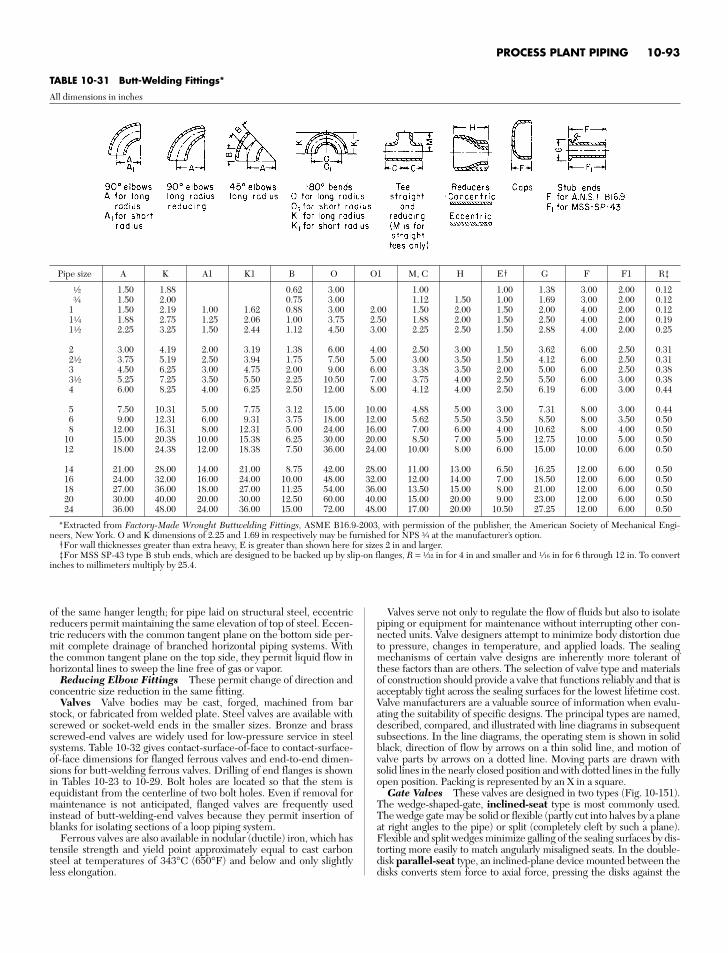
PROCESS PLANT PIPING 10-93
TABLE 10-31 Butt-Welding Fittings*
All dimensions in inches
Pipe size A K A1 K1 B O O1 M, C H E† G F F1 R‡
a 1.50 1.88 0.62 3.00 1.00 1.00 1.38 3.00 2.00 0.12e 1.50 2.00 0.75 3.00 1.12 1.50 1.00 1.69 3.00 2.00 0.12
1 1.50 2.19 1.00 1.62 0.88 3.00 2.00 1.50 2.00 1.50 2.00 4.00 2.00 0.121d 1.88 2.75 1.25 2.06 1.00 3.75 2.50 1.88 2.00 1.50 2.50 4.00 2.00 0.191a 2.25 3.25 1.50 2.44 1.12 4.50 3.00 2.25 2.50 1.50 2.88 4.00 2.00 0.25
2 3.00 4.19 2.00 3.19 1.38 6.00 4.00 2.50 3.00 1.50 3.62 6.00 2.50 0.312a 3.75 5.19 2.50 3.94 1.75 7.50 5.00 3.00 3.50 1.50 4.12 6.00 2.50 0.313 4.50 6.25 3.00 4.75 2.00 9.00 6.00 3.38 3.50 2.00 5.00 6.00 2.50 0.383a 5.25 7.25 3.50 5.50 2.25 10.50 7.00 3.75 4.00 2.50 5.50 6.00 3.00 0.384 6.00 8.25 4.00 6.25 2.50 12.00 8.00 4.12 4.00 2.50 6.19 6.00 3.00 0.44
5 7.50 10.31 5.00 7.75 3.12 15.00 10.00 4.88 5.00 3.00 7.31 8.00 3.00 0.446 9.00 12.31 6.00 9.31 3.75 18.00 12.00 5.62 5.50 3.50 8.50 8.00 3.50 0.508 12.00 16.31 8.00 12.31 5.00 24.00 16.00 7.00 6.00 4.00 10.62 8.00 4.00 0.50
10 15.00 20.38 10.00 15.38 6.25 30.00 20.00 8.50 7.00 5.00 12.75 10.00 5.00 0.5012 18.00 24.38 12.00 18.38 7.50 36.00 24.00 10.00 8.00 6.00 15.00 10.00 6.00 0.50
14 21.00 28.00 14.00 21.00 8.75 42.00 28.00 11.00 13.00 6.50 16.25 12.00 6.00 0.5016 24.00 32.00 16.00 24.00 10.00 48.00 32.00 12.00 14.00 7.00 18.50 12.00 6.00 0.5018 27.00 36.00 18.00 27.00 11.25 54.00 36.00 13.50 15.00 8.00 21.00 12.00 6.00 0.5020 30.00 40.00 20.00 30.00 12.50 60.00 40.00 15.00 20.00 9.00 23.00 12.00 6.00 0.5024 36.00 48.00 24.00 36.00 15.00 72.00 48.00 17.00 20.00 10.50 27.25 12.00 6.00 0.50
*Extracted from Factory-Made Wrought Buttwelding Fittings, ASME B16.9-2003, with permission of the publisher, the American Society of Mechanical Engi-neers, New York. O and K dimensions of 2.25 and 1.69 in respectively may be furnished for NPS e at the manufacturer’s option.
†For wall thicknesses greater than extra heavy, E is greater than shown here for sizes 2 in and larger.‡For MSS SP-43 type B stub ends, which are designed to be backed up by slip-on flanges, R = h in for 4 in and smaller and g in for 6 through 12 in. To convert
inches to millimeters multiply by 25.4.
of the same hanger length; for pipe laid on structural steel, eccentricreducers permit maintaining the same elevation of top of steel. Eccen-tric reducers with the common tangent plane on the bottom side per-mit complete drainage of branched horizontal piping systems. Withthe common tangent plane on the top side, they permit liquid flow inhorizontal lines to sweep the line free of gas or vapor.
Reducing Elbow Fittings These permit change of direction andconcentric size reduction in the same fitting.
Valves Valve bodies may be cast, forged, machined from barstock, or fabricated from welded plate. Steel valves are available withscrewed or socket-weld ends in the smaller sizes. Bronze and brassscrewed-end valves are widely used for low-pressure service in steelsystems. Table 10-32 gives contact-surface-of-face to contact-surface-of-face dimensions for flanged ferrous valves and end-to-end dimen-sions for butt-welding ferrous valves. Drilling of end flanges is shownin Tables 10-23 to 10-29. Bolt holes are located so that the stem isequidistant from the centerline of two bolt holes. Even if removal formaintenance is not anticipated, flanged valves are frequently usedinstead of butt-welding-end valves because they permit insertion ofblanks for isolating sections of a loop piping system.
Ferrous valves are also available in nodular (ductile) iron, which hastensile strength and yield point approximately equal to cast carbonsteel at temperatures of 343°C (650°F) and below and only slightlyless elongation.
Valves serve not only to regulate the flow of fluids but also to isolatepiping or equipment for maintenance without interrupting other con-nected units. Valve designers attempt to minimize body distortion dueto pressure, changes in temperature, and applied loads. The sealingmechanisms of certain valve designs are inherently more tolerant ofthese factors than are others. The selection of valve type and materialsof construction should provide a valve that functions reliably and that isacceptably tight across the sealing surfaces for the lowest lifetime cost.Valve manufacturers are a valuable source of information when evalu-ating the suitability of specific designs. The principal types are named,described, compared, and illustrated with line diagrams in subsequentsubsections. In the line diagrams, the operating stem is shown in solidblack, direction of flow by arrows on a thin solid line, and motion ofvalve parts by arrows on a dotted line. Moving parts are drawn withsolid lines in the nearly closed position and with dotted lines in the fullyopen position. Packing is represented by an X in a square.
Gate Valves These valves are designed in two types (Fig. 10-151).The wedge-shaped-gate, inclined-seat type is most commonly used.The wedge gate may be solid or flexible (partly cut into halves by a planeat right angles to the pipe) or split (completely cleft by such a plane).Flexible and split wedges minimize galling of the sealing surfaces by dis-torting more easily to match angularly misaligned seats. In the double-disk parallel-seat type, an inclined-plane device mounted between thedisks converts stem force to axial force, pressing the disks against the
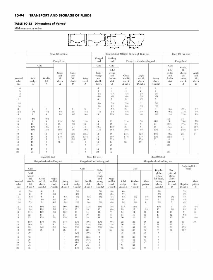
10-94 TRANSPORT AND STORAGE OF FLUIDS
TABLE 10-32 Dimensions of Valves*
All dimensions in inches
Class 125 cast iron Class 150 steel, MSS-SP-42 through 12-in size Class 250 cast iron
Flanged WeldingFlanged end end end Flanged end and welding end Flanged end
Gate Gate Gate GateGlobe,
Solid Solid liftGlobe Angle Solid wedge wedge check, Angle
and and wedge and Globe Angle and and andNominal Solid Double lift lift Swing and double and lift and lift Swing double swing lift
valve wedge disk check check check double disk check check check disk check checksize A A A D A disk A B A and B D and E A and B A A D
d 4 4 4 2 4r 4 4 4 2 4a 4d 4d 4d 2d 4de 4v 4v 4v 2a 4v
1 5 5 5 2e 5
1d 5a 5a 5a 3 5a1a 6a 6a 6a 3d 6a2 7 7 8 4 8 7 8a 8 4 8 8a 10a 5d2a 7a 7a 8a 4d 8a 7a 9a 8a 4d 8a 9a 11a 5e3 8 8 9a 4e 9a 8 11f 9a 4e 9a 11f 12a 6d
3a 8a 8a † 12 14 74 9 9 11a 5e 11a 9 12 11a 5e 11a 15 15e 77⁄85 10 10 13 6a 13 10 15 14 7 13 157⁄8 17a 8e6 10a 10a 14 7 14 10a 157⁄8 16 8 14 16a 21 10a8 11a 11a 19a 9e 19a 11a 16a 19a 9e 19a 18 24a 12d
10 13 13 24a 12d 24a 13 18 24a 12d 24a 19e 28 1412 14 14 27a 13e 27a 14 19e 27a 13e 27a 22a †14 15 † 31 15a 31 15 22a 31 15a 31 24 †16 16 † 36 18 † 16 24 36 18 † 2618 17 † † 17 26 † 28
20 18 † † 18 28 †24 20 † † 20 32 † 31
Class 300 steel Class 400 steel Class 600 steel
Flanged end and welding end Flanged end and welding end Flanged end and welding end
Angle and liftGate Gate
Globe,Gate
Regular Shortcheck
Solid lift globe, pattern‡wedge check, regular globe,
and Globe Angle and Angle lift check, shortNominal double and lift and lift Swing Solid Double swing and lift Solid Double Short swing pattern Short
valve disk check check check wedge disk check check wedge disk pattern‡ check lift check Regular patternsize A and B A and B D and E A and B A and B A and B A and B D and E A and B A and B B A and B B D and E E
a 5a 6 3 6a 6a 3d 6a 6a 3de 6 7 3a 7a 7a 3e 7a 7a 3e
1 6a§ 8 4 8a 8a 8a 8a 4d 8a 8a 5d 8a 5d 4d1d 7§ 8a 4d 9 9 9 9 4a 9 9 5e 9 5e 4a1a 7a 9 4a 9a 9a 9a 9a 4e 9a 9a 6 9a 6 4e
2 8a 10a 5d 10a 11a 11a 11a 5e 11a 11a 7 11a 7 5e 4d2a 9a 11a 5e 11a 13 13 13 6a 13 13 8a 13 8a 6a 53 11f 12a 6d 12a 14 14 14 7 14 14 10 14 10 7 64 12 14 7 14 16 16 16 8 17 17 12 17 12 8a 75 15 15e 77⁄8 15e 18 18 18 9 20 20 15 20 15 10 8a
6 157⁄8 17a 8e 17a 19a 19a 19a 9e 22 22 18 22 18 11 108 16a 22 11 21 23a 23a 23a 11e 26 26 23 26 23 13
10 18 24a 12d 24a 26a 26a 26a 13d 31 31 28 31 28 15a12 19e 28 14 28 30 30 30 15 33 33 32 33 32 16a14 30 † 32a 30a † 35 35 35 †
16 33 † 35a 35a † 39 39 39 †18 36 † 38a 38a † 43 43 43 †20 39 † 41a 41a † 47 47 47 †22 43 † 45 45 † 51 51 †24 45 † 48a 48a † 55 55 55 †
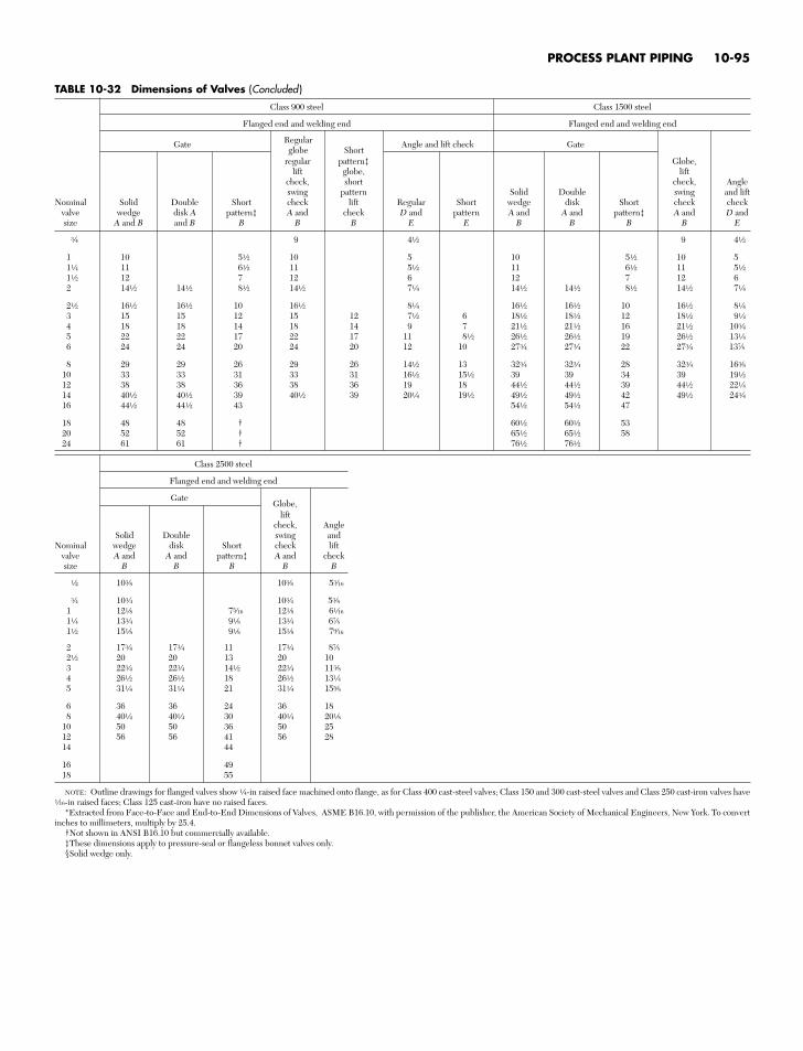
PROCESS PLANT PIPING 10-95
TABLE 10-32 Dimensions of Valves (Concluded )
Class 900 steel Class 1500 steel
Flanged end and welding end Flanged end and welding end
RegularGateglobe Short
Angle and lift check Gate
regular pattern‡ Globe,lift globe, lift
check, short check, Angleswing pattern Solid Double swing and lift
Nominal Solid Double Short check lift Regular Short wedge disk Short check checkvalve wedge disk A pattern‡ A and check D and pattern A and A and pattern‡ A and D andsize A and B and B B B B E E B B B B E
e 9 4a 9 4a
1 10 5a 10 5 10 5a 10 51d 11 6a 11 5a 11 6a 11 5a1a 12 7 12 6 12 7 12 62 14a 14a 8a 14a 7d 14a 14a 8a 14a 7d
2a 16a 16a 10 16a 8d 16a 16a 10 16a 8d3 15 15 12 15 12 7a 6 18a 18a 12 18a 9d4 18 18 14 18 14 9 7 21a 21a 16 21a 10e5 22 22 17 22 17 11 8a 26a 26a 19 26a 13d6 24 24 20 24 20 12 10 27e 27e 22 27e 137⁄8
8 29 29 26 29 26 14a 13 32e 32e 28 32e 16r10 33 33 31 33 31 16a 15a 39 39 34 39 19a12 38 38 36 38 36 19 18 44a 44a 39 44a 22d14 40a 40a 39 40a 39 20d 19a 49a 49a 42 49a 24e16 44a 44a 43 54a 54a 47
18 48 48 † 60a 60a 5320 52 52 † 65a 65a 5824 61 61 † 76a 76a
Class 2500 steel
Flanged end and welding end
GateGlobe,
liftcheck, Angle
Solid Double swing andNominal wedge disk Short check lift
valve A and A and pattern‡ A and checksize B B B B B
a 10r 10r 5t
e 10e 10e 5r1 12f 7b 12f 6g1d 13e 9f 13e 67⁄81a 15f 9f 15f 7z
2 17e 17e 11 17e 87⁄82a 20 20 13 20 103 22e 22e 14a 22e 11r4 26a 26a 18 26a 13d5 31d 31d 21 31d 15v
6 36 36 24 36 188 40d 40d 30 40d 20f
10 50 50 36 50 2512 56 56 41 56 2814 44
16 4918 55
NOTE: Outline drawings for flanged valves show d-in raised face machined onto flange, as for Class 400 cast-steel valves; Class 150 and 300 cast-steel valves and Class 250 cast-iron valves haveg-in raised faces; Class 125 cast-iron have no raised faces.
*Extracted from Face-to-Face and End-to-End Dimensions of Valves, ASME B16.10, with permission of the publisher, the American Society of Mechanical Engineers, New York. To convertinches to millimeters, multiply by 25.4.
†Not shown in ANSI B16.10 but commercially available.‡These dimensions apply to pressure-seal or flangeless bonnet valves only.§Solid wedge only.
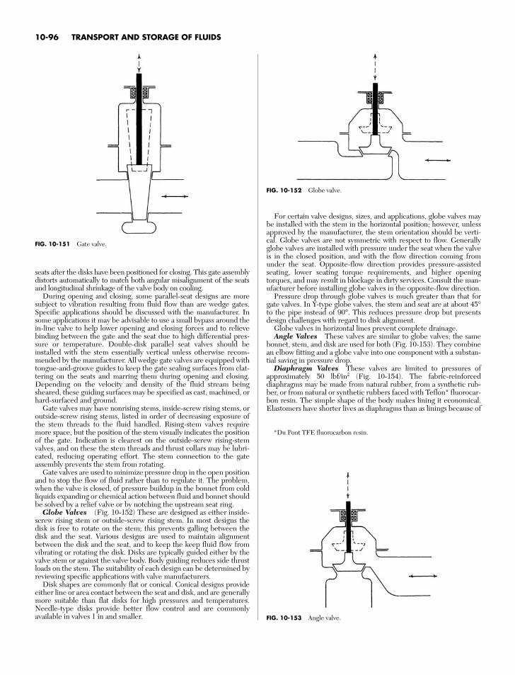
10-96 TRANSPORT AND STORAGE OF FLUIDS
FIG. 10-152 Globe valve.
FIG. 10-153 Angle valve.
*Du Pont TFE fluorocarbon resin.
seats after the disks have been positioned for closing. This gate assemblydistorts automatically to match both angular misalignment of the seatsand longitudinal shrinkage of the valve body on cooling.
During opening and closing, some parallel-seat designs are moresubject to vibration resulting from fluid flow than are wedge gates.Specific applications should be discussed with the manufacturer. Insome applications it may be advisable to use a small bypass around thein-line valve to help lower opening and closing forces and to relievebinding between the gate and the seat due to high differential pres-sure or temperature. Double-disk parallel seat valves should beinstalled with the stem essentially vertical unless otherwise recom-mended by the manufacturer. All wedge gate valves are equipped withtongue-and-groove guides to keep the gate sealing surfaces from clat-tering on the seats and marring them during opening and closing.Depending on the velocity and density of the fluid stream beingsheared, these guiding surfaces may be specified as cast, machined, orhard-surfaced and ground.
Gate valves may have nonrising stems, inside-screw rising stems, oroutside-screw rising stems, listed in order of decreasing exposure ofthe stem threads to the fluid handled. Rising-stem valves requiremore space, but the position of the stem visually indicates the positionof the gate. Indication is clearest on the outside-screw rising-stemvalves, and on these the stem threads and thrust collars may be lubri-cated, reducing operating effort. The stem connection to the gateassembly prevents the stem from rotating.
Gate valves are used to minimize pressure drop in the open positionand to stop the flow of fluid rather than to regulate it. The problem,when the valve is closed, of pressure buildup in the bonnet from coldliquids expanding or chemical action between fluid and bonnet shouldbe solved by a relief valve or by notching the upstream seat ring.
Globe Valves (Fig. 10-152) These are designed as either inside-screw rising stem or outside-screw rising stem. In most designs thedisk is free to rotate on the stem; this prevents galling between thedisk and the seat. Various designs are used to maintain alignmentbetween the disk and the seat, and to keep the keep fluid flow fromvibrating or rotating the disk. Disks are typically guided either by thevalve stem or against the valve body. Body guiding reduces side thrustloads on the stem. The suitability of each design can be determined byreviewing specific applications with valve manufacturers.
Disk shapes are commonly flat or conical. Conical designs provideeither line or area contact between the seat and disk, and are generallymore suitable than flat disks for high pressures and temperatures.Needle-type disks provide better flow control and are commonlyavailable in valves 1 in and smaller.
FIG. 10-151 Gate valve.
For certain valve designs, sizes, and applications, globe valves maybe installed with the stem in the horizontal position; however, unlessapproved by the manufacturer, the stem orientation should be verti-cal. Globe valves are not symmetric with respect to flow. Generallyglobe valves are installed with pressure under the seat when the valveis in the closed position, and with the flow direction coming fromunder the seat. Opposite-flow direction provides pressure-assistedseating, lower seating torque requirements, and higher openingtorques, and may result in blockage in dirty services. Consult the man-ufacturer before installing globe valves in the opposite-flow direction.
Pressure drop through globe valves is much greater than that forgate valves. In Y-type globe valves, the stem and seat are at about 45°to the pipe instead of 90°. This reduces pressure drop but presentsdesign challenges with regard to disk alignment.
Globe valves in horizontal lines prevent complete drainage.Angle Valves These valves are similar to globe valves; the same
bonnet, stem, and disk are used for both (Fig. 10-153). They combinean elbow fitting and a globe valve into one component with a substan-tial saving in pressure drop.
Diaphragm Valves These valves are limited to pressures ofapproximately 50 lbf/in2 (Fig. 10-154). The fabric-reinforceddiaphragms may be made from natural rubber, from a synthetic rub-ber, or from natural or synthetic rubbers faced with Teflon* fluorocar-bon resin. The simple shape of the body makes lining it economical.Elastomers have shorter lives as diaphragms than as linings because of
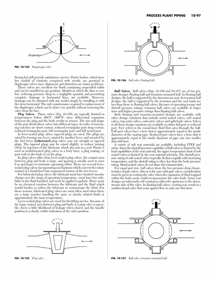
flexing but still provide satisfactory service. Plastic bodies, which havelow moduli of elasticity compared with metals, are practical indiaphragm valves since alignment and distortion are minor problems.
These valves are excellent for fluids containing suspended solidsand can be installed in any position. Models in which the dam is verylow, reducing pressure drop to a negligible quantity and permittingcomplete drainage in horizontal lines, are available. However,drainage can be obtained with any model simply by installing it withthe stem horizontal. The only maintenance required is replacement ofthe diaphragm, which can be done very quickly without removing thevalve from the line.
Plug Valves These valves (Fig. 10-155) are typically limited totemperatures below 260°C (500°F) since differential expansionbetween the plug and the body results in seizure. The size and shapeof the port divide these valves into different types. In order of increas-ing cost they are short venturi, reduced rectangular port; long venturi,reduced rectangular port; full rectangular port; and full round port.
In lever-sealed plug valves, tapered plugs are used. The plugs areraised by turning one lever, rotated by another lever, and reseated bythe first lever. Lubricated plug valves may use straight or taperedplugs. The tapered plugs may be raised slightly, to reduce turningeffort, by injection of the lubricant, which also acts as a seal. Plastic isused in nonlubricated plug valves as a body liner, a plug coating, orport seals in the body or on the plug.
In plug valves other than lever-sealed plug valves, the contact areabetween plug and body is large, and gearing is usually used in sizes6 in and larger to minimize operating effort. There are several lever-sealed plug valves incorporating mechanisms which convert the rotarymotion of a handwheel into sequenced motion of the two levers.
For lubricated plug valves, the lubricant must have limited viscositychange over the range of operating temperature, must have low solu-bility in the fluid handled, and must be applied regularly. There mustbe no chemical reaction between the lubricant and the fluid whichwould harden or soften the lubricant or contaminate the fluid. Forthese reasons, lubricated plug valves are most often used when thereare a large number handling the same or closely related fluids atapproximately the same temperature.
Lever-sealed plug valves are used for throttling service. Because ofthe large contact area between plug and body, if a plug valve is opera-ble, there is little likelihood of leakage when closed, and the handleposition is a clearly visible indication of the valve position.
Ball Valves Ball valves (Figs. 10-156 and 10-157) are of two pri-mary designs, floating ball and trunnion-mounted ball. In floating balldesigns, the ball is supported by the downstream seat. In trunnion balldesigns, the ball is supported by the trunnion and the seat loads areless than those in floating ball valves. Because of operating torque andshutoff pressure ratings, trunnion ball valves are available in largersizes and higher pressure ratings than floating ball valves.
Both floating and trunnion-mounted designs are available withother design variations that include metal seated valves, soft seatedvalves, top-entry valves, end-entry valves, and split body valves. Valvesin all these design variations are available as either full port or reducedport. Port refers to the round-bore fluid flow area through the ball.Full port valves have a bore that is approximately equal to the insidediameter of the mating pipe. Reduced port valves have a bore that isapproximately equal to the inside diameter of pipe one size smallerthan full bore.
A variety of soft seat materials are available, including PTFE andnylon. Since the shutoff pressure capability of ball valves is limited by theload capabilities of the seat material, the upper temperature limit of softseated valves is limited by the seat material selection. The shutoff pres-sure rating of soft seated valves typically declines rapidly with increasingtemperature, and the shutoff rating is often less than the body pressurerating. Metal seated valves do not share this characteristic.
For equal port size, ball valves share the low pressure drop charac-teristics of gate valves. Also as is the case with gate valves, considerationmust be given to venting the valve when the expansion of fluid trappedwithin the body cavity could overpressurize the valve body. Some seatdesigns are inherently self-venting to either the upstream or the down-stream side of the valve. In floating ball valves, venting may result in aunidirectional valve that seats against flow in only one direction.
PROCESS PLANT PIPING 10-97
FIG. 10-154 Diaphragm valve.
FIG. 10-155 Plug valve.
FIG. 10-156 Ball valve; floating ball.
FIG. 10-157 Ball valve; trunnion-mounted ball.
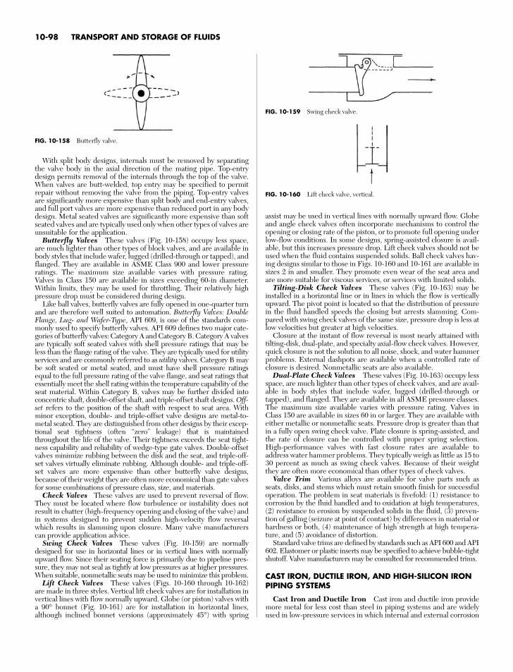
10-98 TRANSPORT AND STORAGE OF FLUIDS
FIG. 10-159 Swing check valve.
FIG. 10-160 Lift check valve, vertical.
With split body designs, internals must be removed by separatingthe valve body in the axial direction of the mating pipe. Top-entrydesign permits removal of the internals through the top of the valve.When valves are butt-welded, top entry may be specified to permitrepair without removing the valve from the piping. Top-entry valvesare significantly more expensive than split body and end-entry valves,and full port valves are more expensive than reduced port in any bodydesign. Metal seated valves are significantly more expensive than softseated valves and are typically used only when other types of valves areunsuitable for the application.
Butterfly Valves These valves (Fig. 10-158) occupy less space,are much lighter than other types of block valves, and are available inbody styles that include wafer, lugged (drilled-through or tapped), andflanged. They are available in ASME Class 900 and lower pressureratings. The maximum size available varies with pressure rating.Valves in Class 150 are available in sizes exceeding 60-in diameter.Within limits, they may be used for throttling. Their relatively highpressure drop must be considered during design.
Like ball valves, butterfly valves are fully opened in one-quarter turnand are therefore well suited to automation. Butterfly Valves: DoubleFlange, Lug- and Wafer-Type, API 609, is one of the standards com-monly used to specify butterfly valves. API 609 defines two major cate-gories of butterfly valves: Category A and Category B. Category A valvesare typically soft seated valves with shell pressure ratings that may beless than the flange rating of the valve. They are typically used for utilityservices and are commonly referred to as utility valves. Category B maybe soft seated or metal seated, and must have shell pressure ratingsequal to the full pressure rating of the valve flange, and seat ratings thatessentially meet the shell rating within the temperature capability of theseat material. Within Category B, valves may be further divided intoconcentric shaft, double-offset shaft, and triple-offset shaft designs. Off-set refers to the position of the shaft with respect to seat area. Withminor exception, double- and triple-offset valve designs are metal-to-metal seated. They are distinguished from other designs by their excep-tional seat tightness (often “zero” leakage) that is maintainedthroughout the life of the valve. Their tightness exceeds the seat tight-ness capability and reliability of wedge-type gate valves. Double-offsetvalves minimize rubbing between the disk and the seat, and triple-off-set valves virtually eliminate rubbing. Although double- and triple-off-set valves are more expensive than other butterfly valve designs,because of their weight they are often more economical than gate valvesfor some combinations of pressure class, size, and materials.
Check Valves These valves are used to prevent reversal of flow.They must be located where flow turbulence or instability does notresult in chatter (high-frequency opening and closing of the valve) andin systems designed to prevent sudden high-velocity flow reversalwhich results in slamming upon closure. Many valve manufacturerscan provide application advice.
Swing Check Valves These valves (Fig. 10-159) are normallydesigned for use in horizontal lines or in vertical lines with normallyupward flow. Since their seating force is primarily due to pipeline pres-sure, they may not seal as tightly at low pressures as at higher pressures.When suitable, nonmetallic seats may be used to minimize this problem.
Lift Check Valves These valves (Figs. 10-160 through 10-162)are made in three styles. Vertical lift check valves are for installation invertical lines with flow normally upward. Globe (or piston) valves witha 90° bonnet (Fig. 10-161) are for installation in horizontal lines,although inclined bonnet versions (approximately 45°) with spring
assist may be used in vertical lines with normally upward flow. Globeand angle check valves often incorporate mechanisms to control theopening or closing rate of the piston, or to promote full opening underlow-flow conditions. In some designs, spring-assisted closure is avail-able, but this increases pressure drop. Lift check valves should not beused when the fluid contains suspended solids. Ball check valves hav-ing designs similar to those in Figs. 10-160 and 10-161 are available insizes 2 in and smaller. They promote even wear of the seat area andare more suitable for viscous services, or services with limited solids.
Tilting-Disk Check Valves These valves (Fig. 10-163) may beinstalled in a horizontal line or in lines in which the flow is verticallyupward. The pivot point is located so that the distribution of pressurein the fluid handled speeds the closing but arrests slamming. Com-pared with swing check valves of the same size, pressure drop is less atlow velocities but greater at high velocities.
Closure at the instant of flow reversal is most nearly attained withtilting-disk, dual-plate, and specialty axial-flow check valves. However,quick closure is not the solution to all noise, shock, and water hammerproblems. External dashpots are available when a controlled rate ofclosure is desired. Nonmetallic seats are also available.
Dual-Plate Check Valves These valves (Fig. 10-163) occupy lessspace, are much lighter than other types of check valves, and are avail-able in body styles that include wafer, lugged (drilled-through ortapped), and flanged. They are available in all ASME pressure classes.The maximum size available varies with pressure rating. Valves inClass 150 are available in sizes 60 in or larger. They are available witheither metallic or nonmetallic seats. Pressure drop is greater than thatin a fully open swing check valve. Plate closure is spring-assisted, andthe rate of closure can be controlled with proper spring selection.High-performance valves with fast closure rates are available toaddress water hammer problems. They typically weigh as little as 15 to30 percent as much as swing check valves. Because of their weightthey are often more economical than other types of check valves.
Valve Trim Various alloys are available for valve parts such asseats, disks, and stems which must retain smooth finish for successfuloperation. The problem in seat materials is fivefold: (1) resistance tocorrosion by the fluid handled and to oxidation at high temperatures,(2) resistance to erosion by suspended solids in the fluid, (3) preven-tion of galling (seizure at point of contact) by differences in material orhardness or both, (4) maintenance of high strength at high tempera-ture, and (5) avoidance of distortion.
Standard valve trims are defined by standards such as API 600 and API602. Elastomer or plastic inserts may be specified to achieve bubble-tightshutoff. Valve manufacturers may be consulted for recommended trims.
CAST IRON, DUCTILE IRON, AND HIGH-SILICON IRONPIPING SYSTEMS
Cast Iron and Ductile Iron Cast iron and ductile iron providemore metal for less cost than steel in piping systems and are widelyused in low-pressure services in which internal and external corrosion
FIG. 10-158 Butterfly valve.
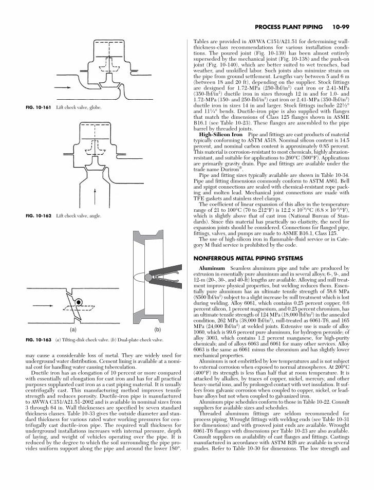
PROCESS PLANT PIPING 10-99
FIG. 10-161 Lift check valve, globe.
FIG. 10-162 Lift check valve, angle.
(a) (b)
FIG. 10-163 (a) Tilting-disk check valve. (b) Dual-plate check valve.
Tables are provided in AWWA C151/A21.51 for determining wall-thickness-class recommendations for various installation condi-tions. The poured joint (Fig. 10-139) has been almost entirelysuperseded by the mechanical joint (Fig. 10-138) and the push-onjoint (Fig. 10-140), which are better suited to wet trenches, badweather, and unskilled labor. Such joints also minimize strain onthe pipe from ground settlement. Lengths vary between 5 and 6 m(between 18 and 20 ft), depending on the supplier. Stock fittingsare designed for 1.72-MPa (250-lbf/in2) cast iron or 2.41-MPa(350-lbf/in2) ductile iron in sizes through 12 in and for 1.0- and1.72-MPa (150- and 250-lbf/in2) cast iron or 2.41-MPa (350-lbf/in2)ductile iron in sizes 14 in and larger. Stock fittings include 221⁄2°and 111⁄4° bends. Ductile-iron pipe is also supplied with flangesthat match the dimensions of Class 125 flanges shown in ASMEB16.1 (see Table 10-23). These flanges are assembled to the pipebarrel by threaded joints.
High-Silicon Iron Pipe and fittings are cast products of materialtypically conforming to ASTM A518. Nominal silicon content is 14.5percent, and nominal carbon content is approximately 0.85 percent.This material is corrosion-resistant to most chemicals, highly abrasion-resistant, and suitable for applications to 260°C (500°F). Applicationsare primarily gravity drain. Pipe and fittings are available under thetrade name Duriron®.
Pipe and fitting sizes typically available are shown in Table 10-34.Pipe and fitting dimensions commonly conform to ASTM A861. Belland spigot connections are sealed with chemical-resistant rope pack-ing and molten lead. Mechanical joint connections are made withTFE gaskets and stainless steel clamps.
The coefficient of linear expansion of this alloy in the temperaturerange of 21 to 100°C (70 to 212°F) is 12.2 × 10⁻⁶/°C (6.8 × 10⁻⁶/°F),which is slightly above that of cast iron (National Bureau of Stan-dards). Since this material has practically no elasticity, the need forexpansion joints should be considered. Connections for flanged pipe,fittings, valves, and pumps are made to ASME B16.1, Class 125.
The use of high-silicon iron in flammable-fluid service or in Cate-gory M fluid service is prohibited by the code.
NONFERROUS METAL PIPING SYSTEMS
Aluminum Seamless aluminum pipe and tube are produced byextrusion in essentially pure aluminum and in several alloys; 6-, 9-, and12-m (20-, 30-, and 40-ft) lengths are available. Alloying and mill treat-ment improve physical properties, but welding reduces them. Essen-tially pure aluminum has an ultimate tensile strength of 58.6 MPa(8500 lbf/in2) subject to a slight increase by mill treatment which is lostduring welding. Alloy 6061, which contains 0.25 percent copper, 0.6percent silicon, 1 percent magnesium, and 0.25 percent chromium, hasan ultimate tensile strength of 124 MPa (18,000 lbf/in2) in the annealedcondition, 262 MPa (38,000 lbf/in2), mill-treated as 6061-T6, and 165MPa (24,000 lbf/in2) at welded joints. Extensive use is made of alloy1060, which is 99.6 percent pure aluminum, for hydrogen peroxide; ofalloy 3003, which contains 1.2 percent manganese, for high-puritychemicals; and of alloys 6063 and 6061 for many other services. Alloy6063 is the same as 6061 minus the chromium and has slightly lowermechanical properties.
Aluminum is not embrittled by low temperatures and is not subjectto external corrosion when exposed to normal atmospheres. At 200°C(400°F) its strength is less than half that at room temperature. It isattacked by alkalies, by traces of copper, nickel, mercury, and otherheavy-metal ions, and by prolonged contact with wet insulation. It suf-fers from galvanic corrosion when coupled to copper, nickel, or lead-base alloys but not when coupled to galvanized iron.
Aluminum pipe schedules conform to those in Table 10-22. Consultsuppliers for available sizes and schedules.
Threaded aluminum fittings are seldom recommended forprocess piping. Wrought fittings with welding ends (see Table 10-31for dimensions) and with grooved joint ends are available. Wrought6061-T6 flanges with dimensions per Table 10-23 are also available.Consult suppliers on availability of cast flanges and fittings. Castingsmanufactured in accordance with ASTM B26 are available in severalgrades. Refer to Table 10-30 for dimensions. The low strength and
may cause a considerable loss of metal. They are widely used forunderground water distribution. Cement lining is available at a nomi-nal cost for handling water causing tuberculation.
Ductile iron has an elongation of 10 percent or more comparedwith essentially nil elongation for cast iron and has for all practicalpurposes supplanted cast iron as a cast piping material. It is usuallycentrifugally cast. This manufacturing method improves tensilestrength and reduces porosity. Ductile-iron pipe is manufacturedto AWWA C151/A21.51-2002 and is available in nominal sizes from3 through 64 in. Wall thicknesses are specified by seven standardthickness classes. Table 10-33 gives the outside diameter and stan-dard thickness for various rated water working pressures for cen-trifugally cast ductile-iron pipe. The required wall thickness forunderground installations increases with internal pressure, depthof laying, and weight of vehicles operating over the pipe. It isreduced by the degree to which the soil surrounding the pipe pro-vides uniform support along the pipe and around the lower 180°.
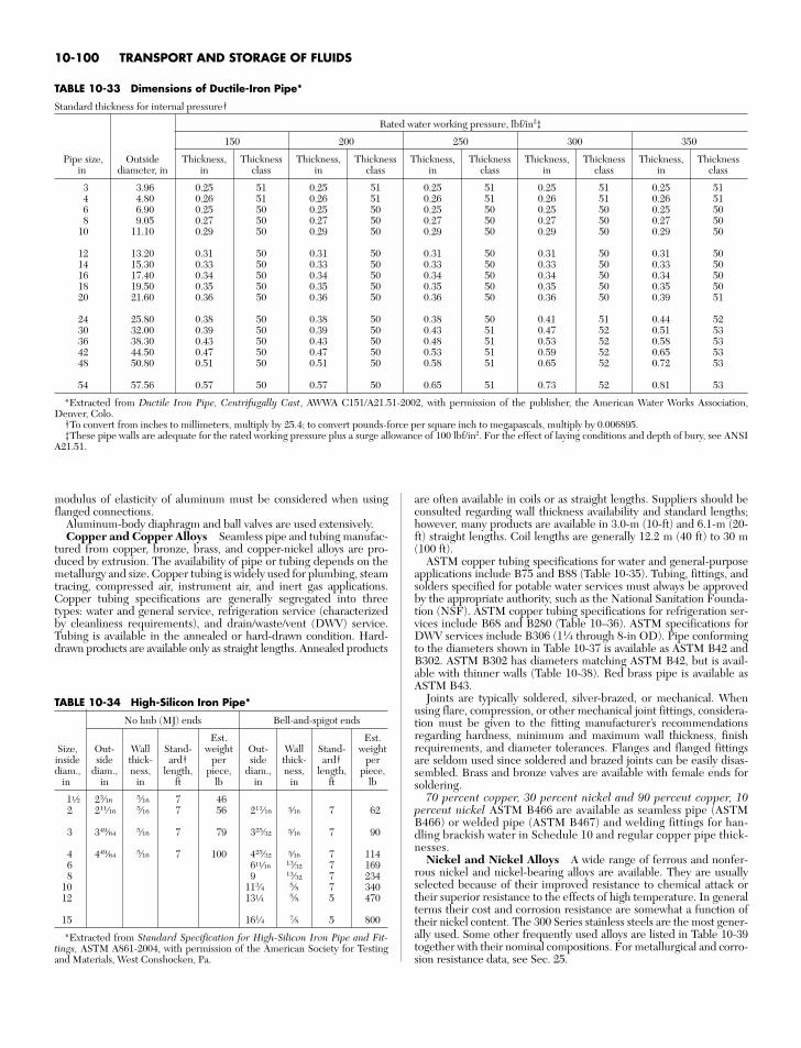
10-100 TRANSPORT AND STORAGE OF FLUIDS
TABLE 10-33 Dimensions of Ductile-Iron Pipe*
Standard thickness for internal pressure†
Rated water working pressure, lbf/in2‡
150 200 250 300 350
Pipe size, Outside Thickness, Thickness Thickness, Thickness Thickness, Thickness Thickness, Thickness Thickness, Thicknessin diameter, in in class in class in class in class in class
3 3.96 0.25 51 0.25 51 0.25 51 0.25 51 0.25 514 4.80 0.26 51 0.26 51 0.26 51 0.26 51 0.26 516 6.90 0.25 50 0.25 50 0.25 50 0.25 50 0.25 508 9.05 0.27 50 0.27 50 0.27 50 0.27 50 0.27 50
10 11.10 0.29 50 0.29 50 0.29 50 0.29 50 0.29 50
12 13.20 0.31 50 0.31 50 0.31 50 0.31 50 0.31 5014 15.30 0.33 50 0.33 50 0.33 50 0.33 50 0.33 5016 17.40 0.34 50 0.34 50 0.34 50 0.34 50 0.34 5018 19.50 0.35 50 0.35 50 0.35 50 0.35 50 0.35 5020 21.60 0.36 50 0.36 50 0.36 50 0.36 50 0.39 51
24 25.80 0.38 50 0.38 50 0.38 50 0.41 51 0.44 5230 32.00 0.39 50 0.39 50 0.43 51 0.47 52 0.51 5336 38.30 0.43 50 0.43 50 0.48 51 0.53 52 0.58 5342 44.50 0.47 50 0.47 50 0.53 51 0.59 52 0.65 5348 50.80 0.51 50 0.51 50 0.58 51 0.65 52 0.72 53
54 57.56 0.57 50 0.57 50 0.65 51 0.73 52 0.81 53
*Extracted from Ductile Iron Pipe, Centrifugally Cast, AWWA C151/A21.51-2002, with permission of the publisher, the American Water Works Association,Denver, Colo.
†To convert from inches to millimeters, multiply by 25.4; to convert pounds-force per square inch to megapascals, multiply by 0.006895.‡These pipe walls are adequate for the rated working pressure plus a surge allowance of 100 lbf/in2. For the effect of laying conditions and depth of bury, see ANSI
A21.51.
modulus of elasticity of aluminum must be considered when usingflanged connections.
Aluminum-body diaphragm and ball valves are used extensively.Copper and Copper Alloys Seamless pipe and tubing manufac-
tured from copper, bronze, brass, and copper-nickel alloys are pro-duced by extrusion. The availability of pipe or tubing depends on themetallurgy and size. Copper tubing is widely used for plumbing, steamtracing, compressed air, instrument air, and inert gas applications.Copper tubing specifications are generally segregated into threetypes: water and general service, refrigeration service (characterizedby cleanliness requirements), and drain/waste/vent (DWV) service.Tubing is available in the annealed or hard-drawn condition. Hard-drawn products are available only as straight lengths. Annealed products
are often available in coils or as straight lengths. Suppliers should beconsulted regarding wall thickness availability and standard lengths;however, many products are available in 3.0-m (10-ft) and 6.1-m (20-ft) straight lengths. Coil lengths are generally 12.2 m (40 ft) to 30 m(100 ft).
ASTM copper tubing specifications for water and general-purposeapplications include B75 and B88 (Table 10-35). Tubing, fittings, andsolders specified for potable water services must always be approvedby the appropriate authority, such as the National Sanitation Founda-tion (NSF). ASTM copper tubing specifications for refrigeration ser-vices include B68 and B280 (Table 10–36). ASTM specifications forDWV services include B306 (11⁄4 through 8-in OD). Pipe conformingto the diameters shown in Table 10-37 is available as ASTM B42 andB302. ASTM B302 has diameters matching ASTM B42, but is avail-able with thinner walls (Table 10-38). Red brass pipe is available asASTM B43.
Joints are typically soldered, silver-brazed, or mechanical. Whenusing flare, compression, or other mechanical joint fittings, considera-tion must be given to the fitting manufacturer’s recommendationsregarding hardness, minimum and maximum wall thickness, finishrequirements, and diameter tolerances. Flanges and flanged fittingsare seldom used since soldered and brazed joints can be easily disas-sembled. Brass and bronze valves are available with female ends forsoldering.
70 percent copper, 30 percent nickel and 90 percent copper, 10percent nickel ASTM B466 are available as seamless pipe (ASTMB466) or welded pipe (ASTM B467) and welding fittings for han-dling brackish water in Schedule 10 and regular copper pipe thick-nesses.
Nickel and Nickel Alloys A wide range of ferrous and nonfer-rous nickel and nickel-bearing alloys are available. They are usuallyselected because of their improved resistance to chemical attack ortheir superior resistance to the effects of high temperature. In generalterms their cost and corrosion resistance are somewhat a function oftheir nickel content. The 300 Series stainless steels are the most gener-ally used. Some other frequently used alloys are listed in Table 10-39together with their nominal compositions. For metallurgical and corro-sion resistance data, see Sec. 25.
TABLE 10-34 High-Silicon Iron Pipe*
No hub (MJ) ends Bell-and-spigot ends
Est. Est.Size, Out- Wall Stand- weight Out- Wall Stand- weightinside side thick- ard† per side thick- ard† perdiam., diam., ness, length, piece, diam., ness, length, piece,
in in in ft lb in in ft lb
1a 23⁄16 5⁄16 7 462 211⁄16 5⁄16 7 56 211⁄16 b 7 62
3 349⁄64 5⁄16 7 79 325⁄32 b 7 90
4 449⁄64 5⁄16 7 100 425⁄32 b 7 1146 6x 13⁄32 7 1698 9 13⁄32 7 234
10 113⁄4 5⁄8 7 34012 13d 5⁄8 5 470
15 161⁄4 7⁄8 5 800
*Extracted from Standard Specification for High-Silicon Iron Pipe and Fit-tings, ASTM A861-2004, with permission of the American Society for Testingand Materials, West Conshocken, Pa.
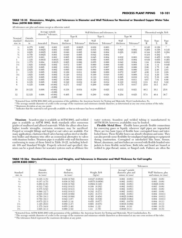
Titanium Seamless pipe is available as ASTM B861, and weldedpipe is available as ASTM B862. Both standards offer numerousgrades of unalloyed and alloyed materials. While the alloys often havehigher tensile strengths, corrosion resistance may be sacrificed.Forged or wrought fittings and forged or cast valves are available. Formany applications, elastomer-lined valves having carbon-steel or ductile-iron bodies and titanium trim offer an economical alternative to valveswith titanium bodies. Titanium pipe is available with wall thicknessesconforming to many of those listed in Table 10-22, including Sched-ule 10S and Standard Weight. Properly selected and specified, tita-nium can be a good choice for seawater systems such as offshore fire
water systems. Seamless and welded tubing is manufactured toASTM B338; however, availability may be limited.
Flexible Metal Hose Flexible hoses provide flexible connectionsfor conveying gases or liquids, wherever rigid pipes are impractical.There are two basic types of flexible hose: corrugated hoses and inter-locked hoses. These flexible hoses can absorb vibrations and noise. Theycan also provide some flexibility for misaligned rigid piping or equipmentduring construction. Corrugated or interlocked thin brass, bronze,Monel, aluminum, and steel tubes are covered with flexible braided-wirejackets to form flexible metal hose. Both tube and braid are brazed orwelded to pipe-thread, union, or flanged ends. Failures are often the
TABLE 10-35 Dimensions, Weights, and Tolerances in Diameter and Wall Thickness for Nominal or Standard Copper Water TubeSizes (ASTM B88-2003)*
All tolerances are plus and minus except as otherwise noted.
Average outsidediameterA tolerance,
Wall thickness and tolerances, in Theoretical weight, lb/ft
Nominal Outsidein Type K Type L Type M
standard diameter, Wall Wall Wall Type Type Typesize, in in Annealed Drawn thickness ToleranceB thickness ToleranceB thickness ToleranceB K L M
d 0.375 0.002 0.001 0.035 0.0035 0.030 0.003 C C 0.145 0.126 C
3⁄3 0.500 0.0025 0.001 0.049 0.005 0.035 0.004 0.025 0.002 0.269 0.198 0.145a 0.625 0.0025 0.001 0.049 0.005 0.040 0.004 0.028 0.003 0.344 0.285 0.2045⁄8 0.750 0.0025 0.001 0.049 0.005 0.042 0.004 C C 0.418 0.362 C
e 0.875 0.003 0.001 0.065 0.006 0.045 0.004 0.032 0.003 0.641 0.455 0.3281 1.125 0.0035 0.0015 0.065 0.006 0.050 0.005 0.035 0.004 0.839 0.655 0.4651d 1.375 0.004 0.0015 0.065 0.006 0.055 0.006 0.042 0.004 1.04 0.884 0.6821a 1.625 0.0045 0.002 0.072 0.007 0.060 0.006 0.049 0.005 1.36 1.14 0.9402 2.125 0.005 0.002 0.083 0.008 0.070 0.007 0.058 0.006 2.06 1.75 1.462a 2.625 0.005 0.002 0.095 0.010 0.080 0.008 0.065 0.006 2.93 2.48 2.033 3.125 0.005 0.002 0.109 0.011 0.090 0.009 0.072 0.007 4.00 3.33 2.683a 3.625 0.005 0.002 0.120 0.012 0.100 0.010 0.083 0.008 5.12 4.29 3.584 4.125 0.005 0.002 0.134 0.013 0.110 0.011 0.095 0.010 6.51 5.38 4.665 5.125 0.005 0.002 0.160 0.016 0.125 0.012 0.109 0.011 9.67 7.61 6.666 6.125 0.005 0.002 0.192 0.019 0.140 0.014 0.122 0.012 13.9 10.2 8.928 8.125 0.006 +0.002 0.271 0.027 0.200 0.020 0.170 0.017 25.9 19.3 16.5
−0.00410 10.125 0.008 +0.002 0.338 0.034 0.250 0.025 0.212 0.021 40.3 30.1 25.6
−0.00612 12.125 0.008 +0.002 0.405 0.040 0.280 0.028 0.254 0.025 57.8 40.4 36.7
−0.006
*Extracted from ASTM B88-2003 with permission of the publisher, the American Society for Testing and Materials, West Conshohocken, Pa.A The average outside diameter of a tube is the average of the maximum and minimum outside diameter, as determined at any one cross section of the tube.B Maximum deviation at any one point.C Indicates that the material is not generally available or that no tolerance has been established.
PROCESS PLANT PIPING 10-101
TABLE 10-36a Standard Dimensions and Weights, and Tolerances in Diameter and Wall Thickness for Coil Lengths (ASTM B280-2003*)
Tolerances
Outside Wall AverageA outsideStandard diameter, thickness, Weight, lb/ft diameter, plus and WallB thickness, plussize, in in (mm) in (mm) (kg/m) minus, in (mm) and minus, in (mm)
f 0.125 (3.18) 0.030 (0.762) 0.0347 (0.0516) 0.002 (0.051) 0.003 (0.08)t 0.187 (4.75) 0.030 (0.762) 0.0575 (0.0856) 0.002 (0.051) 0.003 (0.08)d 0.250 (6.35) 0.030 (0.762) 0.0804 (0.120) 0.002 (0.051) 0.0025 (0.08)b 0.312 (7.92) 0.032 (0.813) 0.109 (0.162) 0.002 (0.051) 0.003 (0.08)r 0.375 (9.52) 0.032 (0.813) 0.134 (0.199) 0.002 (0.051) 0.003 (0.08)a 0.500 (12.7) 0.032 (0.813) 0.182 (0.271) 0.002 (0.051) 0.003 (0.08)v 0.625 (15.9) 0.035 (0.889) 0.251 (0.373) 0.002 (0.051) 0.004 (0.011)e 0.750 (19.1) 0.042 (0.889) 0.305 (0.454) 0.0025 (0.064) 0.004 (0.011)e 0.750 (19.1) 0.042 (1.07) 0.362 (0.539) 0.0025 (0.064) 0.004 (0.011)7⁄8 0.875 (22.3) 0.045 (1.14) 0.455 (0.677) 0.003 (0.076) 0.004 (0.11)
1f 1.125 (28.6) 0.050 (1.27) 0.665 (0.975) 0.0035 (0.089) 0.005 (0.13)1r 1.375 (34.9) 0.055 (1.40) 0.884 (1.32) 0.004 (0.10) 0.006 (0.15)1v 1.625 (41.3) 0.060 (1.52) 1.14 (1.70) 0.0045 (0.11) 0.006 (0.15)
*Extracted from ASTM B280-2003 with permission of the publisher, the American Society for Testing and Materials, West Conshohocken, Pa.A The average outside diameter of a tube is the average of the maximum and minimum outside diameters as determined at any one cross section of the tube.B The tolerances listed represent the maximum deviation at any point.
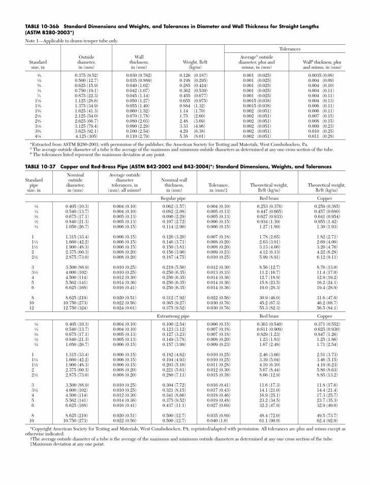
TABLE 10-37 Copper and Red-Brass Pipe (ASTM B42-2002 and B43-2004)*: Standard Dimensions, Weights, and Tolerances
Nominal Average outsideStandard outside diameter Nominal wall
pipe diameter, tolerances, in thickness, Tolerance, Theoretical weight, Theoretical weight,size, in in (mm) (mm), all minus† in (mm) in (mm)‡ lb/ft (kg/m) lb/ft (kg/m)
Regular pipe Red brass Copper
f 0.405 (10.3) 0.004 (0.10) 0.062 (1.57) 0.004 (0.10) 0.253 (0.376) 0.259 (0.385)d 0.540 (13.7) 0.004 (0.10) 0.082 (2.08) 0.005 (0.13) 0.447 (0.665) 0.457 (0.680)r 0.675 (17.1) 0.005 (0.13) 0.090 (2.29) 0.005 (0.13) 0.627 (0.933) 0.641 (0.954)a 0.840 (21.3) 0.005 (0.13) 0.107 (2.72) 0.006 (0.15) 0.934 (1.39) 0.955 (1.42)e 1.050 (26.7) 0.006 (0.15) 0.114 (2.90) 0.006 (0.15) 1.27 (1.89) 1.30 (1.93)
1 1.315 (33.4) 0.006 (0.15) 0.126 (3.20) 0.007 (0.18) 1.78 (2.65) 1.82 (2.71)1d 1.660 (42.2) 0.006 (0.15) 0.146 (3.71) 0.008 (0.20) 2.63 (3.91) 2.69 (4.00)1a 1.900 (48.3) 0.006 (0.15) 0.150 (3.81) 0.008 (0.20) 3.13 (4.66) 3.20 (4.76)2 2.375 (60.3) 0.008 (0.20) 0.156 (3.96) 0.009 (0.23) 4.12 (6.13) 4.22 (6.28)2a 2.875 (73.0) 0.008 (0.20) 0.187 (4.75) 0.010 (0.25) 5.99 (8.91) 6.12 (9.11)
3 3.500 (88.9) 0.010 (0.25) 0.219 (5.56) 0.012 (0.30) 8.56 (12.7) 8.76 (13.0)3a 4.000 (102) 0.010 (0.25) 0.250 (6.35) 0.013 (0.33) 11.2 (16.7) 11.4 (17.0)4 4.500 (114) 0.012 (0.30) 0.250 (6.35) 0.014 (0.36) 12.7 (18.9) 12.9 (19.2)5 5.562 (141) 0.014 (0.36) 0.250 (6.35) 0.014 (0.36) 15.8 (23.5) 16.2 (24.1)6 6.625 (168) 0.016 (0.41) 0.250 (6.35) 0.014 (0.36) 19.0 (28.3) 19.4 (28.9)
8 8.625 (219) 0.020 (0.51) 0.312 (7.92) 0.022 (0.56) 30.9 (46.0) 31.6 (47.0)10 10.750 (273) 0.022 (0.56) 0.365 (9.27) 0.030 (0.76) 45.2 (67.3) 46.2 (68.7)12 12.750 (324) 0.024 (0.61) 0.375 (9.52) 0.030 (0.76) 55.3 (82.3) 56.5 (84.1)
Extrastrong pipe Red brass Copper
f 0.405 (10.3) 0.004 (0.10) 0.100 (2.54) 0.006 (0.15) 0.363 (0.540) 0.371 (0.552)d 0.540 (13.7) 0.004 (0.10) 0.123 (3.12) 0.007 (0.18) 0.611 (0.909) 0.625 (0.930)r 0.675 (17.1) 0.005 (0.13) 0.127 (3.23) 0.007 (0.18) 0.829 (1.23) 0.847 (1.26)a 0.840 (21.3) 0.005 (0.13) 0.149 (3.78) 0.008 (0.20) 1.23 (1.83) 1.25 (1.86)e 1.050 (26.7) 0.006 (0.15) 0.157 (3.99) 0.009 (0.23) 1.67 (2.48) 1.71 (2.54)
1 1.315 (33.4) 0.006 (0.15) 0.182 (4.62) 0.010 (0.25) 2.46 (3.66) 2.51 (3.73)1d 1.660 (42.2) 0.006 (0.15) 0.194 (4.93) 0.010 (0.25) 3.39 (5.04) 3.46 (5.15)1a 1.900 (48.3) 0.006 (0.15) 0.203 (5.16) 0.011 (0.28) 4.10 (6.10) 4.19 (6.23)2 2.375 (60.3) 0.008 (0.20) 0.221 (5.61) 0.012 (0.30) 5.67 (8.44) 5.80 (8.63)2a 2.875 (73.0) 0.008 (0.20) 0.280 (7.11) 0.015 (0.38) 8.66 (12.9) 8.85 (13.2)
3 3.500 (88.9) 0.010 (0.25) 0.304 (7.72) 0.016 (0.41) 11.6 (17.3) 11.8 (17.6)3a 4.000 (102) 0.010 (0.25) 0.321 (8.15) 0.017 (0.43) 14.1 (21.0) 14.4 (21.4)4 4.500 (114) 0.012 (0.30) 0.341 (8.66) 0.018 (0.46) 16.9 (25.1) 17.3 (25.7)5 5.562 (141) 0.014 (0.36) 0.375 (9.52) 0.019 (0.48) 23.2 (34.5) 23.7 (35.3)6 6.625 (168) 0.016 (0.41) 0.437 (11.1) 0.027 (0.69) 32.2 (47.9) 32.9 (49.0)
8 8.625 (219) 0.020 (0.51) 0.500 (12.7) 0.035 (0.89) 48.4 (72.0) 49.5 (73.7)10 10.750 (273) 0.022 (0.56) 0.500 (12.7) 0.040 (1.0) 61.1 (90.9) 62.4 (92.9)
*Copyright American Society for Testing and Materials, West Conshohocken, PA; reprinted/adapted with permission. All tolerances are plus and minus except asotherwise indicated.
†The average outside diameter of a tube is the average of the maximum and minimum outside diameters as determined at any one cross section of the tube.‡Maximum deviation at any one point.
TABLE 10-36b Standard Dimensions and Weights, and Tolerances in Diameter and Wall Thickness for Straight Lengths (ASTM B280-2003*)
Note 1—Applicable to drawn temper tube only.
Tolerances
Outside Wall AverageA outsideStandard diameter, thickness, Weight, lb/ft diameter, plus and WallB thickness, plussize, in in (mm) in (mm) (kg/m) minus, in (mm) and minus, in (mm)
r 0.375 (9.52) 0.030 (0.762) 0.126 (0.187) 0.001 (0.025) 0.0035 (0.08)a 0.500 (12.7) 0.035 (0.889) 0.198 (0.295) 0.001 (0.025) 0.004 (0.09)v 0.625 (15.9) 0.040 (1.02) 0.285 (0.424) 0.001 (0.025) 0.004 (0.10)e 0.750 (19.1) 0.042 (1.07) 0.362 (0.539) 0.001 (0.025) 0.004 (0.11)7⁄8 0.875 (22.3) 0.045 (1.14) 0.455 (0.677) 0.001 (0.025) 0.004 (0.11)
1f 1.125 (28.6) 0.050 (1.27) 0.655 (0.975) 0.0015 (0.038) 0.004 (0.13)1r 1.375 (34.9) 0.055 (1.40) 0.884 (1.32) 0.0015 (0.038) 0.006 (0.11)1v 1.625 (41.3) 0.060 (1.52) 1.14 (1.70) 0.002 (0.051) 0.006 (0.11)2f 2.125 (54.0) 0.070 (1.78) 1.75 (2.60) 0.002 (0.051) 0.007 (0.15)2v 2.625 (66.7) 0.080 (2.03) 2.48 (3.69) 0.002 (0.051) 0.008 (0.15)3f 3.125 (79.4) 0.090 (2.29) 3.33 (4.96) 0.002 (0.051) 0.009 (0.23)3v 3.625 (92.1) 0.100 (2.54) 4.29 (6.38) 0.002 (0.051) 0.010 (0.25)4f 4.125 (105) 0.110 (2.79) 5.38 (8.01) 0.002 (0.051) 0.011 (0.28)
*Extracted from ASTM B280-2003, with permission of the publisher, the American Society for Testing and Materials, West Conshohocken, Pa.A The average outside diameter of a tube is the average of the maximum and minimum outside diameters as determined at any one cross section of the tube.B The tolerances listed represent the maximum deviation at any point.
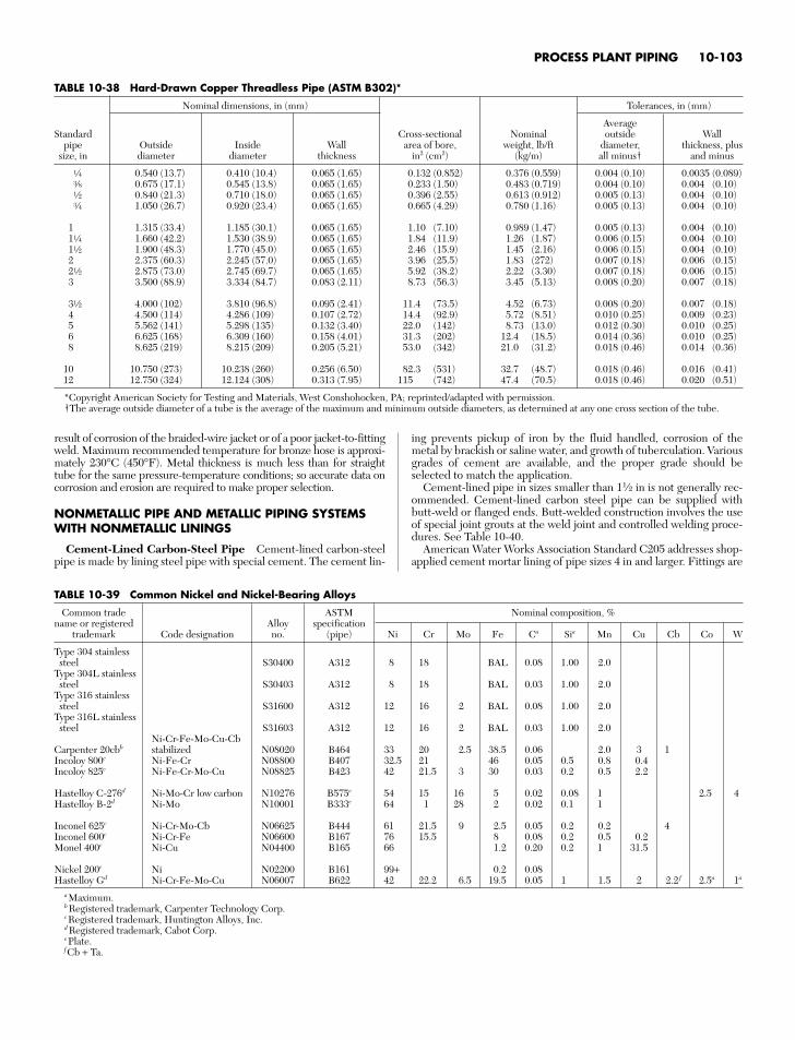
result of corrosion of the braided-wire jacket or of a poor jacket-to-fittingweld. Maximum recommended temperature for bronze hose is approxi-mately 230°C (450°F). Metal thickness is much less than for straighttube for the same pressure-temperature conditions; so accurate data oncorrosion and erosion are required to make proper selection.
NONMETALLIC PIPE AND METALLIC PIPING SYSTEMSWITH NONMETALLIC LININGS
Cement-Lined Carbon-Steel Pipe Cement-lined carbon-steelpipe is made by lining steel pipe with special cement. The cement lin-
ing prevents pickup of iron by the fluid handled, corrosion of themetal by brackish or saline water, and growth of tuberculation. Variousgrades of cement are available, and the proper grade should beselected to match the application.
Cement-lined pipe in sizes smaller than 11⁄2 in is not generally rec-ommended. Cement-lined carbon steel pipe can be supplied withbutt-weld or flanged ends. Butt-welded construction involves the useof special joint grouts at the weld joint and controlled welding proce-dures. See Table 10-40.
American Water Works Association Standard C205 addresses shop-applied cement mortar lining of pipe sizes 4 in and larger. Fittings are
PROCESS PLANT PIPING 10-103
TABLE 10-38 Hard-Drawn Copper Threadless Pipe (ASTM B302)*
Nominal dimensions, in (mm) Tolerances, in (mm)
AverageStandard Cross-sectional Nominal outside Wall
pipe Outside Inside Wall area of bore, weight, lb/ft diameter, thickness, plussize, in diameter diameter thickness in2 (cm2) (kg/m) all minus† and minus
d 0.540 (13.7) 0.410 (10.4) 0.065 (1.65) 0.132 (0.852) 0.376 (0.559) 0.004 (0.10) 0.0035 (0.089)r 0.675 (17.1) 0.545 (13.8) 0.065 (1.65) 0.233 (1.50) 0.483 (0.719) 0.004 (0.10) 0.004 (0.10)a 0.840 (21.3) 0.710 (18.0) 0.065 (1.65) 0.396 (2.55) 0.613 (0.912) 0.005 (0.13) 0.004 (0.10)e 1.050 (26.7) 0.920 (23.4) 0.065 (1.65) 0.665 (4.29) 0.780 (1.16) 0.005 (0.13) 0.004 (0.10)
1 1.315 (33.4) 1.185 (30.1) 0.065 (1.65) 1.10 (7.10) 0.989 (1.47) 0.005 (0.13) 0.004 (0.10)1d 1.660 (42.2) 1.530 (38.9) 0.065 (1.65) 1.84 (11.9) 1.26 (1.87) 0.006 (0.15) 0.004 (0.10)1a 1.900 (48.3) 1.770 (45.0) 0.065 (1.65) 2.46 (15.9) 1.45 (2.16) 0.006 (0.15) 0.004 (0.10)2 2.375 (60.3) 2.245 (57.0) 0.065 (1.65) 3.96 (25.5) 1.83 (272) 0.007 (0.18) 0.006 (0.15)2a 2.875 (73.0) 2.745 (69.7) 0.065 (1.65) 5.92 (38.2) 2.22 (3.30) 0.007 (0.18) 0.006 (0.15)3 3.500 (88.9) 3.334 (84.7) 0.083 (2.11) 8.73 (56.3) 3.45 (5.13) 0.008 (0.20) 0.007 (0.18)
3a 4.000 (102) 3.810 (96.8) 0.095 (2.41) 11.4 (73.5) 4.52 (6.73) 0.008 (0.20) 0.007 (0.18)4 4.500 (114) 4.286 (109) 0.107 (2.72) 14.4 (92.9) 5.72 (8.51) 0.010 (0.25) 0.009 (0.23)5 5.562 (141) 5.298 (135) 0.132 (3.40) 22.0 (142) 8.73 (13.0) 0.012 (0.30) 0.010 (0.25)6 6.625 (168) 6.309 (160) 0.158 (4.01) 31.3 (202) 12.4 (18.5) 0.014 (0.36) 0.010 (0.25)8 8.625 (219) 8.215 (209) 0.205 (5.21) 53.0 (342) 21.0 (31.2) 0.018 (0.46) 0.014 (0.36)
10 10.750 (273) 10.238 (260) 0.256 (6.50) 82.3 (531) 32.7 (48.7) 0.018 (0.46) 0.016 (0.41)12 12.750 (324) 12.124 (308) 0.313 (7.95) 115 (742) 47.4 (70.5) 0.018 (0.46) 0.020 (0.51)
*Copyright American Society for Testing and Materials, West Conshohocken, PA; reprinted/adapted with permission.†The average outside diameter of a tube is the average of the maximum and minimum outside diameters, as determined at any one cross section of the tube.
TABLE 10-39 Common Nickel and Nickel-Bearing Alloys
Common trade ASTM Nominal composition, %name or registered Alloy specification
trademark Code designation no. (pipe) Ni Cr Mo Fe Ca Sia Mn Cu Cb Co W
Type 304 stainlesssteel S30400 A312 8 18 BAL 0.08 1.00 2.0
Type 304L stainlesssteel S30403 A312 8 18 BAL 0.03 1.00 2.0
Type 316 stainlesssteel S31600 A312 12 16 2 BAL 0.08 1.00 2.0
Type 316L stainlesssteel S31603 A312 12 16 2 BAL 0.03 1.00 2.0
Ni-Cr-Fe-Mo-Cu-CbCarpenter 20cbb stabilized N08020 B464 33 20 2.5 38.5 0.06 2.0 3 1Incoloy 800c Ni-Fe-Cr N08800 B407 32.5 21 46 0.05 0.5 0.8 0.4Incoloy 825c Ni-Fe-Cr-Mo-Cu N08825 B423 42 21.5 3 30 0.03 0.2 0.5 2.2
Hastelloy C-276d Ni-Mo-Cr low carbon N10276 B575e 54 15 16 5 0.02 0.08 1 2.5 4Hastelloy B-2d Ni-Mo N10001 B333e 64 1 28 2 0.02 0.1 1
Inconel 625c Ni-Cr-Mo-Cb N06625 B444 61 21.5 9 2.5 0.05 0.2 0.2 4Inconel 600c Ni-Cr-Fe N06600 B167 76 15.5 8 0.08 0.2 0.5 0.2Monel 400c Ni-Cu N04400 B165 66 1.2 0.20 0.2 1 31.5
Nickel 200c Ni N02200 B161 99+ 0.2 0.08Hastelloy Gd Ni-Cr-Fe-Mo-Cu N06007 B622 42 22.2 6.5 19.5 0.05 1 1.5 2 2.2 f 2.5a 1a
aMaximum.bRegistered trademark, Carpenter Technology Corp.cRegistered trademark, Huntington Alloys, Inc.dRegistered trademark, Cabot Corp.ePlate.fCb + Ta.
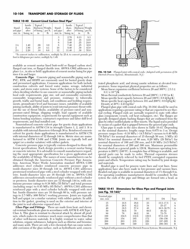
available as cement mortar lined butt-weld or flanged carbon steel,flanged cast iron, or flanged ductile iron. AWWA C602 addresses in-place (i.e., in situ or field) application of cement mortar lining for pipesizes 4 in and larger.
Concrete Pipe Concrete piping and nonmetallic piping such asPVC, RTR, and HDPE are commonly used for buried gravity drainand pressurized applications. Common applications for both includeconstruction culverts and forced water mains, sewage, industrialwaste, and storm water systems. Some of the factors to be consideredwhen deciding whether to use concrete or nonmetallic piping includelocal code requirements, pipe size, soil and commodity corrosivity,commodity temperature and pressure, resistance to tuberculingrowth, traffic and burial loads, soil conditions and bedding require-ments, groundwater level and buoyancy issues, suitability of availablejoining methods, ability of joints to resist internal pressure thrust with-out the use of thrust blocks, availability of pressure-rated and non-pressure-rated fittings, shipping weight, load capacity of availableconstruction equipment, requirements for special equipment such asfusion bonding machines, contractor’s experience and labor skill levelrequirements, and final installed cost.
Nonreinforced concrete culvert pipe for gravity drain applicationsis manufactured to ASTM C14 in strength Classes 1, 2, and 3. It isavailable with internal diameters 4 through 36 in. Reinforced concreteculvert for gravity drain applications is manufactured to ASTM C76with internal diameters of 12 through 144 in. Metric sizes are manu-factured to ASTM C14M and C76M. Joints are typically bell andspigot (or a similar variation) with rubber gaskets.
Concrete pressure pipe is typically custom-designed to three dif-ferent specifications. Each design provides a cement mortar liningor concrete interior. It is advisable to consult manufacturers regard-ing the most appropriate specification for a given application andthe availability of fittings. The names of some manufacturers can beobtained through the American Concrete Pressure Pipe Associa-tion. American Water Works Association standard AWWA C300addresses steel cylinder reinforced concrete pressure pipe ininside-diameter sizes 30 through 144 in. AWWA C301 addressesprestressed reinforced pipe with a steel cylinder wrapped with steelwire. Inside-diameter sizes are 16 through 144 in. AWWA C302addresses circumferentially reinforced pipe without a steel cylinderor prestress. Inside diameter sizes are 12 through 144 in, with con-tinuous pressure ratings to 0.38 MPa (55 lbf/in2) and total pressure(including surge) to 0.45 MPa (65 lbf/in2). AWWA C303 addressesreinforced pipe with a steel cylinder helically wrapped with steelbar. Inside-diameter sizes are 10 through 60 in, with pressure rat-ings to 2.7-MPa (400 lbf/in2) working pressure. Joints are typicallybell and spigot (or a similar variation) with rubber gaskets. In addi-tion to the gasket, grouting is used on the exterior and interior ofthe joint to seal otherwise exposed steel.
Glass Pipe and Fittings These are made from heat- and chemi-cal-resistant borosilicate glass in accordance with ASTM E-438 Type 1Class A. This glass is resistant to chemical attack by almost all prod-ucts, which makes its resistance much more comprehensive than thatof other well-known materials. It is highly resistant to water, salinesolutions, organic substances, halogens such as chlorine and bromine,and many acids. There are only a few chemicals that can cause notice-able corrosion of the glass surface, such as hydrofluoric acid, concen-
trated phosphoric acid, and strong caustic solutions at elevated tem-peratures. Some important physical properties are as follows:
Mean linear expansion coefficient between 20 and 300°C: [(3.3 ±0.1) × 10−6]/K
Mean thermal conductivity between 20 and 200°C: 1.2 W(m K)Mean specific heat capacity between 20 and 100°C: 0.8 kJ/kg(K)Mean specific heat capacity between 101 and 200°C: 0.9 kJ/kg(K)Density at 20°C: 2.23 kg/dm3
Flanged glass pipe with conical ends (Fig. 10-164) should be used inapplications requiring a pressure rating or that are expected to see ther-mal cycling. Flanged ends are normally required to mate with otherglass components (vessels, coil heat exchangers, etc). The flanges arespecially designed plastic backing flanges that are cushioned from theglass by either molded plastic or fiber inserts. The liquid seal is providedby means of a gasket that is gripped between the grooved pipe ends.
Glass pipe is made in the sizes shown in Table 10-41. Dependingon the nominal diameter, lengths range from 0.075 to 3 m. Designpressure ranges from −0.10 MPa (−14.5 lbf/in2) vacuum to 0.40 MPa(58 lbf/in2) for nominal diameters of 15 through 50 mm, 3 MPa (43lbf/in2) for nominal diameter of 80 mm, 0.20 MPa (29 lbf/in2) fornominal diameters of 100 and 150 mm, and 0.10 MPa (14.5 lbf/in2)for nominal diameters of 200 and 300 mm. Maximum permissiblethermal shock as a general guide is 120 K. Maximum operating tem-perature is 200°C (248°F). A complete line of fittings is available, andspecial parts can be made to order. Thermal expansion stressesshould be completely relieved by tied PTFE corrugated expansionjoints and offsets. Temperature rating may be limited by joint designand materials.
Beaded pipe is used for process waste lines and vent lines. Someapplications have also been made in low-pressure and vacuum lines.Beaded end pipe is available in nominal diameters of 11⁄2 through 6 in.For operating conditions manufacturers should be consulted. In thissystem the ends of the pipe and fittings are formed into a bead, as
10-104 TRANSPORT AND STORAGE OF FLUIDS
TABLE 10-40 Cement-Lined Carbon-Steel Pipe*
Inside Typical Inside TypicalStand- diam. thickness Weight, Stand- diam. thickness Weight
ard pipe after of lining, per ft, ard pipe after of lining, per ft,size, in lining, in in lb size, in lining, in in lb
3 2.70 0.13 8.34 3.60 .16 12.06 5.40 .25 24.0
1a 1.40 .09 3.0 8 7.40 .25 32.02 1.80 .10 4.1 10 9.40 .30 43.02a 2.20 .10 6.6 12 11.40 .30 55.0
*To convert inches to millimeters, multiply by 25.4; to convert pounds perfoot to kilograms per meter, multiply by 1.49.
FIG. 10-164 Flanged joint with conical ends. (Adapted with permission of DeDietrich Process Systems, Mountainside, N.J.)
TABLE 10-41 Dimensions for Glass Pipe and Flanged Joints(see Fig. 10-165)*
Nominal pipesize, mm D1 D2 D3 D4 Type
15 16.8 28.6 23 15.5–17.5 A25 26.5 42.2 34 25–27 A40 38.5 57.4 48 36.5–39.75 A50 50.5 70 60.5 48–52 A80 76 99.2 88 72–78 A
100 104.5 132.6 120.5 97.6–110 A150 154 185 172 150–156 A200 203 235 220 197–205 B300 300 340 321 299–303 B
*Adapted with permission of De Dietrich Process Systems, Mountainside, N.J.
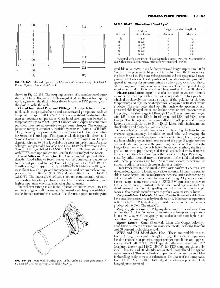
shown in Fig. 10-166. The coupling consists of a stainless steel outershell, a rubber collar, and a TFE liner-gasket. When the single couplingnut is tightened, the thick rubber sleeve forces the TFE gasket againstthe glass to make the seal.
Glass-Lined Steel Pipe and Fittings This pipe is fully resistantto all acids except hydrofluoric and concentrated phosphoric acids attemperatures up to 120°C (248°F). It is also resistant to alkaline solu-tions at moderate temperatures. Glass-lined steel pipe can be used attemperatures up to 220°C (428°F) under some exposure conditionsprovided there are no excessive temperature changes. The operatingpressure rating of commonly available systems is 1 MPa (145 lbf/in2).The glass lining is approximately 1.6 mm (1⁄16 in) thick. It is made by lin-ing Schedule 40 steel pipe. Fittings are available in glass-lined cast steel.Standard nominal pipe sizes available are 11⁄2 through 8 in. Larger-diameter pipe up to 48 in is available on a custom-order basis. A rangeof lengths are generally available. See Table 10-42 for dimensional data.Steel split flanges drilled to ANSI B16.5 Class 150 dimensions alongwith PTFE envelope gaskets are used for the assembly of the system.
Fused Silica or Fused Quartz Containing 99.8 percent silicondioxide, fused silica or fused quartz can be obtained as opaque ortransparent pipe and tubing. The melting point is 1710°C (3100°F).Tensile strength is approximately 48 MPa (7000 lbf/in2); specific grav-ity is about 2.2. The pipe and tubing can be used continuously at tem-peratures up to 1000°C (1830°F) and intermittently up to 1500°C(2730°F). The material’s chief assets are noncontamination of mostchemicals in high-temperature service, thermal-shock resistance, andhigh-temperature electrical insulating characteristics.
Transparent tubing is available in inside diameters from 1 to 125mm in a range of wall thicknesses. Satin-surface tubing is available ininside diameters from 1⁄18 to 2 in, and sand-surface pipe and tubing are
available in 1⁄2- to 24-in inside diameters and lengths up to 6 m (20 ft).Sand-surface pipe and tubing are obtainable in wall thicknesses vary-ing from 1⁄8 to 1 in. Pipe and tubing sections in both opaque and trans-parent fused silica or fused quartz can be readily machine-ground tospecial tolerances for pressure joints or other purposes. Also, fused-silica piping and tubing can be reprocessed to meet special-designrequirements. Manufacturers should be consulted for specific details.
Plastic-Lined Steel Pipe Use of a variety of polymeric materialsas liners for steel pipe rather than as piping systems solves problemswhich the relatively low tensile strength of the polymer at elevatedtemperature and high thermal expansion, compared with steel, wouldproduce. The steel outer shell permits much wider spacing of sup-ports, reliable flanged joints, and higher pressure and temperature inthe piping. The size range is 1 through 12 in. The systems are flangedwith 125-lb cast-iron, 150-lb ductile-iron, and 150- and 300-lb steelflanges. The linings are factory-installed in both pipe and fittings.Lengths are available up to 6 m (20 ft). Lined ball, diaphragm, andcheck valves and plug cocks are available.
One method of manufacture consists of inserting the liner into anoversize, approximately Schedule 40 steel tube and swaging theassembly to produce iron-pipe-size outside diameter, firmly engagingthe liner which projects from both ends of the pipe. Flanges are thenscrewed onto the pipe, and the projecting liner is hot-flared over theflange faces nearly to the bolt holes. In another method, the liner ispushed into steel pipe having cold-flared laps backed up by flanges atthe ends and then hot-flared over the faces of the laps. Pipe lengthsmade by either method may be shortened in the field and reflaredwith special procedures and tools. Square and tapered spacers are fur-nished to adjust for small discrepancies in assembly.
Liner types available are suitable for a wide variety of chemical ser-vices, including acids, alkalies, and various solvents. All liners are perme-able to some degree, and manufacturers use various methods to vent gasout of the interspace between the liner and casing. All plastics are sub-ject to environmental stress cracking (ESC). ESC can occur even whenthe liner is chemically resistant to the service. Lined pipe manufacturersshould always be consulted regarding liner selections and service appli-cations. Also consult manufacturers regarding vacuum service limits.
Polyvinylidene Chloride Liners Polyvinylidene chloride linershave excellent resistance to hydrochloric acid. Maximum temperatureis 80°C (175°F). Polyvinylidene chloride is also known as Saran, aproduct of the Dow Chemical Co.
Polypropylene Liners Polypropylene liners are used in sulfuricacid service. At 10 to 30 percent concentration the upper temperaturelimit is 93°C (200°F). Polypropylene is also suitable for higher con-centrations at lower temperatures.
Kynar Liners Kynar (Pennwalt Chemicals Corp.) polyvinyli-dene fluoride liners are used for many chemicals, including bromineand 50 percent hydrochloric acid.
PTFE and PFA Lined Steel Pipe These are available in sizesfrom 1 through 12 in and in lengths through 6 m (20 ft). Experiencehas determined that practical upper temperature limits are approxi-mately 204°C (400°F) for PTFE (polytetrafluoroethylene) and PFA(perfluoroalkoxy) and 149°C (300°F) for FEP (fluoroethylene poly-mer); Class 150 and 300 ductile-iron or steel flanged lined fittings andvalves are used. The nonadhesive properties of the liner make it idealfor handling sticky or viscous substances. Thickness of the lining variesfrom 1.5 to 3.8 mm (60 to 150 mil), depending on pipe size. Onlyflanged joints are used.
PROCESS PLANT PIPING 10-105
(a) (b)
D2
D3
D1
D4
D2
D3
D1
D4
FIG. 10-165 Flanged pipe ends. (Adapted with permission of De DietrichProcess Systems, Mountainside, N.J.)
FIG. 10-166 Joint with beaded pipe ends. (Adapted with permission of De Dietrich Process Systems, Mountainside, N.J.)
TABLE 10-42 Glass-Lined Steel Pipe*
Outside Range of standard lengths, in
Size, in. diameter, in Minimum Maximum
11⁄2 1.900 6 602 2.375 6 843 3.500 6 1204 4.500 6 1206 6.625 6 1208 8.625 6 120
*Adapted with permission of De Dietrich Process Systems, Mountainside,N.J. Other manufacturers may offer different standard lengths.
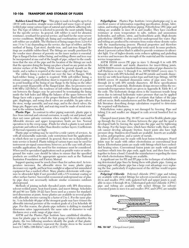
Rubber-Lined Steel Pipe This pipe is made in lengths up to 6 m(20 ft) with seamless, straight seam-welded and some types of spiral-welded pipe using various types of natural and synthetic adhering rub-ber. The type of rubber is selected to provide the most suitable liningfor the specific service. In general, soft rubber is used for abrasionresistance, semihard for general service, and hard for the more severeservice conditions. Multiple-ply lining and combinations of hard andsoft rubber are available. The thickness of lining ranges from 3.2 to 6.4mm (1⁄8 to 1⁄4 in) depending on the service, the type of rubber, and themethod of lining. Cast-steel, ductile-iron, and cast-iron flanged fit-tings are available rubber-lined. The fittings are usually purchased bythe vendor since absence of porosity on the inner surface is essential.Pipe is flanged before rubber lining, and welding elbows and tees maybe incorporated at one end of the length of pipe, subject to the condi-tions that the size of the pipe and the location of the fittings are suchthat the operator doing the lining can place a hand on any point on theinterior surface of the fitting. Welds must be ground smooth on theinside, and a radius is required at the inner edge of the flange face.
The rubber lining is extended out over the face of flanges. Withhard-rubber lining, a gasket is required. With soft-rubber lining, arelease coating or a polyethylene sheet is required in place of a gasketto avoid bonding of the lining of one flange to the lining on the otherand to permit disassembly of the flanged joint. Also, for pressures over0.86 MPa (125 lbf/in2), the tendency of soft-rubber linings to extrudeout between the flanges may be prevented by terminating the lininginside the bolt holes and filling the balance of the space between theflange faces with a spacer of the proper thickness. Hard-rubber-linedgate, diaphragm, and swing check valves are available. In gate valves,the stem, wedge assembly, and seat rings, and in the check valves, thehinge pin, flapper arm, disk, and seat ring must be made of metal resis-tant to the solution handled.
Plastic Pipe In contrast to other piping materials, plastic pipe isfree from internal and external corrosion, is easily cut and joined, anddoes not cause galvanic corrosion when coupled to other materials.Allowable stresses and upper temperature limits are low. Normaloperation is in the creep range. Fluids for which a plastic is not suitedpenetrate and soften it rather than dissolve surface layers. Coefficientsof thermal expansion are high.
Plastic pipe or tubing may be used for a wide variety of services. Aswith all nonmetallic materials, code restrictions limit the applicationsin which their use is permitted. In general, their use in flammable ortoxic service is limited. Plastic tubing of various types may be used forinstrument air-signal connections; however, as is the case with all non-metallic applications, the need for fire resistance must be considered.When used in specialized applications such as potable water or under-ground fire water, care should be taken to ensure that the specifiedproducts are certified by appropriate agencies such as the NationalSanitation Foundation and Factory Mutual.
Support spacing must be much closer than for carbon steel. As tem-perature increases, the allowable stress for many plastic pipesdecreases very rapidly, and heat from sunlight or adjacent hot uninsulatedequipment has a marked effect. Many plastics deteriorate with expo-sure to ultraviolet light if not provided with a UV-resistant coating orother surface barrier. Successful economical underground use of plas-tic pipe does not necessarily indicate similar economies outdoorsaboveground.
Methods of joining include threaded joints with IPS dimensions,solvent-welded joints, heat-fused joints, and insert fittings. Schedules40 and 80 (see Table 10-22) have been used as a source for standard-ized dimensions at joints. Some plastics are available in several gradeswith allowable stresses varying by a factor of 2 to 1. For the same plas-tic, 1⁄2-in Schedule 40 pipe of the strongest grade may have 4 times theallowable internal pressure of the weakest grade of a 2-in Schedule 40pipe. For this reason, the plastic-pipe industry is shifting to standarddimension ratios (approximately the same ratio of diameter to wallthickness over a wide range of pipe sizes).
ASTM and the Plastics Pipe Institute have established identifica-tions for plastic pipe in which the first group of letters identifies theplastic, the two following numbers identify the grade of that plastic,and the last two numbers represent the design stress in the nearestlower 0.7-MPa (100-lbf/in2) unit at 23°C (73.4°F).
Polyethylene Plastics Pipe Institute (www.plasticpipe.org) is anexcellent source of information regarding specification, design, fabri-cation, and testing of polyethylene piping. Polyethylene (PE) pipe andtubing are available in sizes 48 in and smaller. They have excellentresistance at room temperature to salts, sodium and ammoniumhydroxides, and sulfuric, nitric, and hydrochloric acids. High-densitypolyethylene (HDPE) is often used for underground fire water. Pipeand tubing are produced by extrusion from resins whose density varieswith the manufacturing process. Physical properties and thereforewall thickness depend on the particular resin used. In some products,about 3 percent carbon black is added to provide resistance to ultravi-olet light. Use of higher-density resin reduces splitting and pinholingin service and increases the strength of the material and the maximumservice temperature.
ASTM D2104 covers PE pipe in sizes 1⁄2 through 6 in with IPSSchedule 40 outside and inside diameters for insert-fitting joints.ASTM D2239 covers six standard dimension ratios of pipe diameter towall thickness in sizes 1⁄2 through 6 in. ASTM D2447 covers sizes 1⁄2through 12 in with IPS Schedule 40 and 80 outside and inside diame-ters for use with heat-fusion socket-type and butt-type fittings. ASTMD3035 covers 10 standard dimension ratios of pipe sizes from 1⁄2through 24 in with IPS outside diameters. All these specificationscover various PE materials. Hydrostatic design stresses within the rec-ommended temperature limits are given in Appendix B, Table B-1, ofthe code. The hydrostatic design stress is the maximum tensile hoopstress due to internal hydrostatic water pressure that can be appliedcontinuously with a high degree of certainty that failure of the pipewill not occur. Both manufacturers and the Plastic Pipe Institute pub-lish literature describing design calculations required to determinethe required wall thickness.
Polyethylene water piping is not damaged by freezing. Pipe andtubing 2 in and smaller are shipped in coils several hundred feet inlength.
Clamped-insert joints (Fig. 10-167) are used for flexible plastic pipeup through the 2-in size. Friction between the pipe and the spud isdeveloped both by forcing the spud into the pipe and by tighteningthe clamp. For the larger sizes, which have thicker walls, these meth-ods cannot develop adequate friction. Insert joints also have highpressure drop. Stainless-steel bands are available. Inserts are availablein nylon, polypropylene, and a variety of metals.
Joints of all sizes may be made with heat fusion techniques. Fusedjoints may be made with either electrofusion or conventional heatfusion. Electrofusion joints are made with fittings which have embed-ded heating wires. Conventional fusion joints are made with specialmachines which trim the pipe ends, apply heat, and then force themtogether to form a bond. Consult the manufacturer regarding the sizesfor which electrofusion fittings are available.
A significant use for PE and PP pipe is the technique of rehabilitat-ing deteriorated pipe lines by lining them with plastic pipe. Lining anexisting pipe with plastic pipe has a large cost advantage over replac-ing the line, particularly if replacement of the old line would requireexcavation.
Polyvinyl Chloride Polyvinyl chloride (PVC) pipe and tubingare available with socket fittings for solvent-cemented joints in sizes24 in and smaller. PVC with gasketed bell and spigot joints is avail-able in sizes 4 through 48 in. Chlorinated polyvinyl chloride (CPVC)pipe and tubing are available with socket fittings for solvent-cemented joints in sizes 4 in and smaller. PVC and CPVC are suitable
10-106 TRANSPORT AND STORAGE OF FLUIDS
FIG. 10-167 Clamped-insert joint.
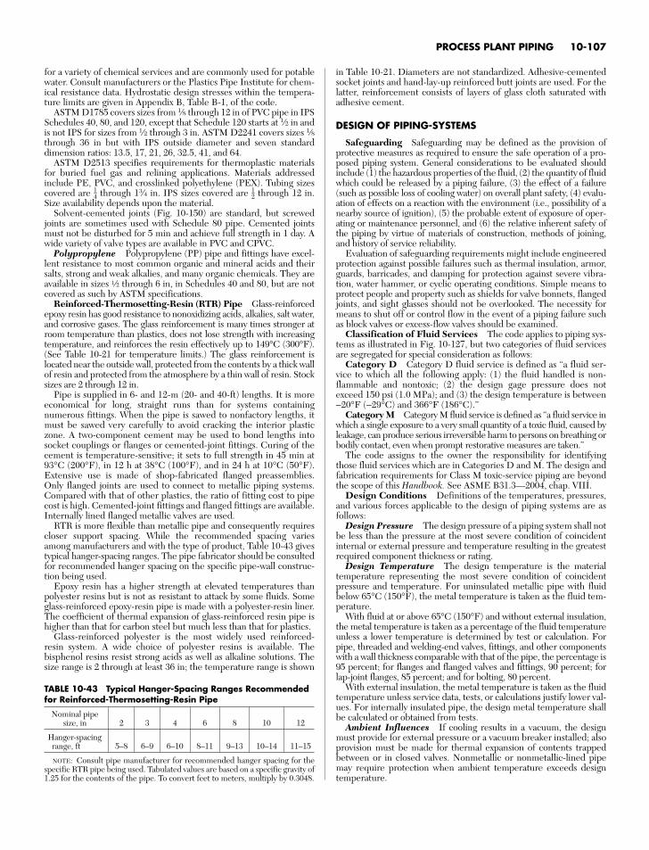
for a variety of chemical services and are commonly used for potablewater. Consult manufacturers or the Plastics Pipe Institute for chem-ical resistance data. Hydrostatic design stresses within the tempera-ture limits are given in Appendix B, Table B-1, of the code.
ASTM D1785 covers sizes from 1⁄8 through 12 in of PVC pipe in IPSSchedules 40, 80, and 120, except that Schedule 120 starts at 1⁄2 in andis not IPS for sizes from 1⁄2 through 3 in. ASTM D2241 covers sizes 1⁄8through 36 in but with IPS outside diameter and seven standarddimension ratios: 13.5, 17, 21, 26, 32.5, 41, and 64.
ASTM D2513 specifies requirements for thermoplastic materialsfor buried fuel gas and relining applications. Materials addressedinclude PE, PVC, and crosslinked polyethylene (PEX). Tubing sizescovered are 14 through 13⁄4 in. IPS sizes covered are 12 through 12 in.Size availability depends upon the material.
Solvent-cemented joints (Fig. 10-150) are standard, but screwedjoints are sometimes used with Schedule 80 pipe. Cemented jointsmust not be disturbed for 5 min and achieve full strength in 1 day. Awide variety of valve types are available in PVC and CPVC.
Polypropylene Polypropylene (PP) pipe and fittings have excel-lent resistance to most common organic and mineral acids and theirsalts, strong and weak alkalies, and many organic chemicals. They areavailable in sizes a through 6 in, in Schedules 40 and 80, but are notcovered as such by ASTM specifications.
Reinforced-Thermosetting-Resin (RTR) Pipe Glass-reinforcedepoxy resin has good resistance to nonoxidizing acids, alkalies, salt water,and corrosive gases. The glass reinforcement is many times stronger atroom temperature than plastics, does not lose strength with increasingtemperature, and reinforces the resin effectively up to 149°C (300°F).(See Table 10-21 for temperature limits.) The glass reinforcement islocated near the outside wall, protected from the contents by a thick wallof resin and protected from the atmosphere by a thin wall of resin. Stocksizes are 2 through 12 in.
Pipe is supplied in 6- and 12-m (20- and 40-ft) lengths. It is moreeconomical for long, straight runs than for systems containingnumerous fittings. When the pipe is sawed to nonfactory lengths, itmust be sawed very carefully to avoid cracking the interior plasticzone. A two-component cement may be used to bond lengths intosocket couplings or flanges or cemented-joint fittings. Curing of thecement is temperature-sensitive; it sets to full strength in 45 min at93°C (200°F), in 12 h at 38°C (100°F), and in 24 h at 10°C (50°F).Extensive use is made of shop-fabricated flanged preassemblies.Only flanged joints are used to connect to metallic piping systems.Compared with that of other plastics, the ratio of fitting cost to pipecost is high. Cemented-joint fittings and flanged fittings are available.Internally lined flanged metallic valves are used.
RTR is more flexible than metallic pipe and consequently requirescloser support spacing. While the recommended spacing variesamong manufacturers and with the type of product, Table 10-43 givestypical hanger-spacing ranges. The pipe fabricator should be consultedfor recommended hanger spacing on the specific pipe-wall construc-tion being used.
Epoxy resin has a higher strength at elevated temperatures thanpolyester resins but is not as resistant to attack by some fluids. Someglass-reinforced epoxy-resin pipe is made with a polyester-resin liner.The coefficient of thermal expansion of glass-reinforced resin pipe ishigher than that for carbon steel but much less than that for plastics.
Glass-reinforced polyester is the most widely used reinforced-resin system. A wide choice of polyester resins is available. Thebisphenol resins resist strong acids as well as alkaline solutions. Thesize range is 2 through at least 36 in; the temperature range is shown
in Table 10-21. Diameters are not standardized. Adhesive-cementedsocket joints and hand-lay-up reinforced butt joints are used. For thelatter, reinforcement consists of layers of glass cloth saturated withadhesive cement.
DESIGN OF PIPING-SYSTEMS
Safeguarding Safeguarding may be defined as the provision ofprotective measures as required to ensure the safe operation of a pro-posed piping system. General considerations to be evaluated shouldinclude (1) the hazardous properties of the fluid, (2) the quantity of fluidwhich could be released by a piping failure, (3) the effect of a failure(such as possible loss of cooling water) on overall plant safety, (4) evalu-ation of effects on a reaction with the environment (i.e., possibility of anearby source of ignition), (5) the probable extent of exposure of oper-ating or maintenance personnel, and (6) the relative inherent safety ofthe piping by virtue of materials of construction, methods of joining,and history of service reliability.
Evaluation of safeguarding requirements might include engineeredprotection against possible failures such as thermal insulation, armor,guards, barricades, and damping for protection against severe vibra-tion, water hammer, or cyclic operating conditions. Simple means toprotect people and property such as shields for valve bonnets, flangedjoints, and sight glasses should not be overlooked. The necessity formeans to shut off or control flow in the event of a piping failure suchas block valves or excess-flow valves should be examined.
Classification of Fluid Services The code applies to piping sys-tems as illustrated in Fig. 10-127, but two categories of fluid servicesare segregated for special consideration as follows:
Category D Category D fluid service is defined as “a fluid ser-vice to which all the following apply: (1) the fluid handled is non-flammable and nontoxic; (2) the design gage pressure does notexceed 150 psi (1.0 MPa); and (3) the design temperature is between−20°F (−29°C) and 366°F (186°C).”
Category M Category M fluid service is defined as “a fluid service inwhich a single exposure to a very small quantity of a toxic fluid, caused byleakage, can produce serious irreversible harm to persons on breathing orbodily contact, even when prompt restorative measures are taken.”
The code assigns to the owner the responsibility for identifyingthose fluid services which are in Categories D and M. The design andfabrication requirements for Class M toxic-service piping are beyondthe scope of this Handbook. See ASME B31.3—2004, chap. VIII.
Design Conditions Definitions of the temperatures, pressures,and various forces applicable to the design of piping systems are asfollows:
Design Pressure The design pressure of a piping system shall notbe less than the pressure at the most severe condition of coincidentinternal or external pressure and temperature resulting in the greatestrequired component thickness or rating.
Design Temperature The design temperature is the materialtemperature representing the most severe condition of coincidentpressure and temperature. For uninsulated metallic pipe with fluidbelow 65°C (150°F), the metal temperature is taken as the fluid tem-perature.
With fluid at or above 65°C (150°F) and without external insulation,the metal temperature is taken as a percentage of the fluid temperatureunless a lower temperature is determined by test or calculation. Forpipe, threaded and welding-end valves, fittings, and other componentswith a wall thickness comparable with that of the pipe, the percentage is95 percent; for flanges and flanged valves and fittings, 90 percent; forlap-joint flanges, 85 percent; and for bolting, 80 percent.
With external insulation, the metal temperature is taken as the fluidtemperature unless service data, tests, or calculations justify lower val-ues. For internally insulated pipe, the design metal temperature shallbe calculated or obtained from tests.
Ambient Influences If cooling results in a vacuum, the designmust provide for external pressure or a vacuum breaker installed; alsoprovision must be made for thermal expansion of contents trappedbetween or in closed valves. Nonmetallic or nonmetallic-lined pipemay require protection when ambient temperature exceeds designtemperature.
PROCESS PLANT PIPING 10-107
TABLE 10-43 Typical Hanger-Spacing Ranges Recommendedfor Reinforced-Thermosetting-Resin Pipe
Nominal pipesize, in 2 3 4 6 8 10 12
Hanger-spacingrange, ft 5–8 6–9 6–10 8–11 9–13 10–14 11–15
NOTE: Consult pipe manufacturer for recommended hanger spacing for thespecific RTR pipe being used. Tabulated values are based on a specific gravity of1.25 for the contents of the pipe. To convert feet to meters, multiply by 0.3048.
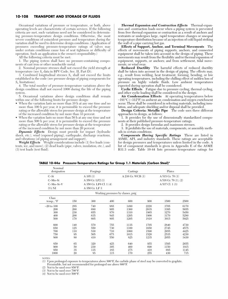
Occasional variations of pressure or temperature, or both, aboveoperating levels are characteristic of certain services. If the followingcriteria are met, such variations need not be considered in determin-ing pressure-temperature design conditions. Otherwise, the mostsevere conditions of coincident pressure and temperature during thevariation shall be used to determine design conditions. (Application ofpressures exceeding pressure-temperature ratings of valves mayunder certain conditions cause loss of seat tightness or difficulty ofoperation. Such an application is the owner’s responsibility.)
All the following criteria must be met:1. The piping system shall have no pressure-containing compo-
nents of cast iron or other nonductile metal.2. Nominal pressure stresses shall not exceed the yield strength at
temperature (see Sy data in BPV Code, Sec. II, Part D).3. Combined longitudinal stresses SL shall not exceed the limits
established in the code (see pressure design of piping components forSL limitations).
4. The total number of pressure-temperature variations above thedesign condition shall not exceed 1000 during the life of the pipingsystem.
5. Occasional variations above design conditions shall remainwithin one of the following limits for pressure design:• When the variation lasts no more than 10 h at any one time and no
more than 100 h per year, it is permissible to exceed the pressurerating or the allowable stress for pressure design at the temperatureof the increased condition by not more than 33 percent.
• When the variation lasts no more than 50 h at any one time and notmore than 500 h per year, it is permissible to exceed the pressurerating or the allowable stress for pressure design at the temperatureof the increased condition by not more than 20 percent.Dynamic Effects Design must provide for impact (hydraulic
shock, etc.), wind (exposed piping), earthquake, discharge reactions,and vibrations (of piping arrangement and support).
Weight Effects Weight considerations include (1) live loads (con-tents, ice, and snow), (2) dead loads (pipe, valves, insulation, etc.), and(3) test loads (test fluid).
Thermal Expansion and Contraction Effects Thermal-expan-sion and -contraction loads occur when a piping system is preventedfrom free thermal expansion or contraction as a result of anchors andrestraints or undergoes large, rapid temperature changes or unequaltemperature distribution because of an injection of cold liquid strikingthe wall of a pipe carrying hot gas.
Effects of Support, Anchor, and Terminal Movements Theeffects of movements of piping supports, anchors, and connectedequipment shall be taken into account in the design of piping. Thesemovements may result from the flexibility and/or thermal expansion ofequipment, supports, or anchors; and from settlement, tidal move-ments, or wind sway.
Reduced Ductility The harmful effects of reduced ductilityshall be taken into account in the design of piping. The effects may,e.g., result from welding, heat treatment, forming, bending, or lowoperating temperatures, including the chilling effect of sudden loss ofpressure on highly volatile fluids. Low ambient temperaturesexpected during operation shall be considered.
Cyclic Effects Fatigue due to pressure cycling, thermal cycling,and other cyclic loading shall be considered in the design.
Air Condensation Effects At operating temperatures below−191°C (−312°F) in ambient air, condensation and oxygen enrichmentoccur. These shall be considered in selecting materials, including insu-lation, and adequate shielding and/or disposal shall be provided.
Design Criteria: Metallic Pipe The code uses three differentapproaches to design, as follows:
1. It provides for the use of dimensionally standardized compo-nents at their published pressure-temperature ratings.
2. It provides design formulas and maximum stresses.3. It prohibits the use of materials, components, or assembly meth-
ods in certain conditions.Components Having Specific Ratings These are listed in
ASME, API, and industry standards. These ratings are acceptablefor design pressures and temperatures unless limited in the code. Alist of component standards is given in Appendix E of the ASMEB31.3 code. Table 10-44 lists pressure–temperature ratings for
10-108 TRANSPORT AND STORAGE OF FLUIDS
TABLE 10-44a Pressure–Temperature Ratings for Group 1.1 Materials (Carbon Steel)*
Nominaldesignation Forgings Castings Plates
C–Si A 105 (1) A 216 Gr. WCB (1) A 515 Gr. 70 (1)C–Mn–Si A 350 Gr. LF2 (1) A 516 Gr. 70 (1), (2)C–Mn–Si–V A 350 Gr. LF6 Cl. 1 (4) A 537 Cl. 1 (3)31⁄2 NI A 350 Gr. LF 3
Working pressures by classes, psig
Classtemp., °F 150 300 400 600 900 1500 2500
−20 to 100 285 740 985 1480 2220 3705 6170200 260 680 905 1360 2035 3395 5655300 230 655 870 1310 1965 3270 5450400 200 635 845 1265 1900 3170 5280500 170 605 805 1205 1810 3015 5025
600 140 570 755 1135 1705 2840 4730650 125 550 730 1100 1650 2745 4575700 110 530 710 1060 1590 2655 4425750 95 505 675 1015 1520 2535 4230800 80 410 550 825 1235 2055 3430
850 65 320 425 640 955 1595 2655900 50 230 305 460 690 1150 1915950 35 135 185 275 410 685 1145
1000 20 85 115 170 255 430 715
NOTES:(1) Upon prolonged exposure to temperatures above 800°F, the carbide phase of steel may be converted to graphite.
Permissible, but not recommended for prolonged use above 800°F.(2) Not to be used over 850°F.(3) Not to be used over 700°F.(4) Not to be used over 500°F.
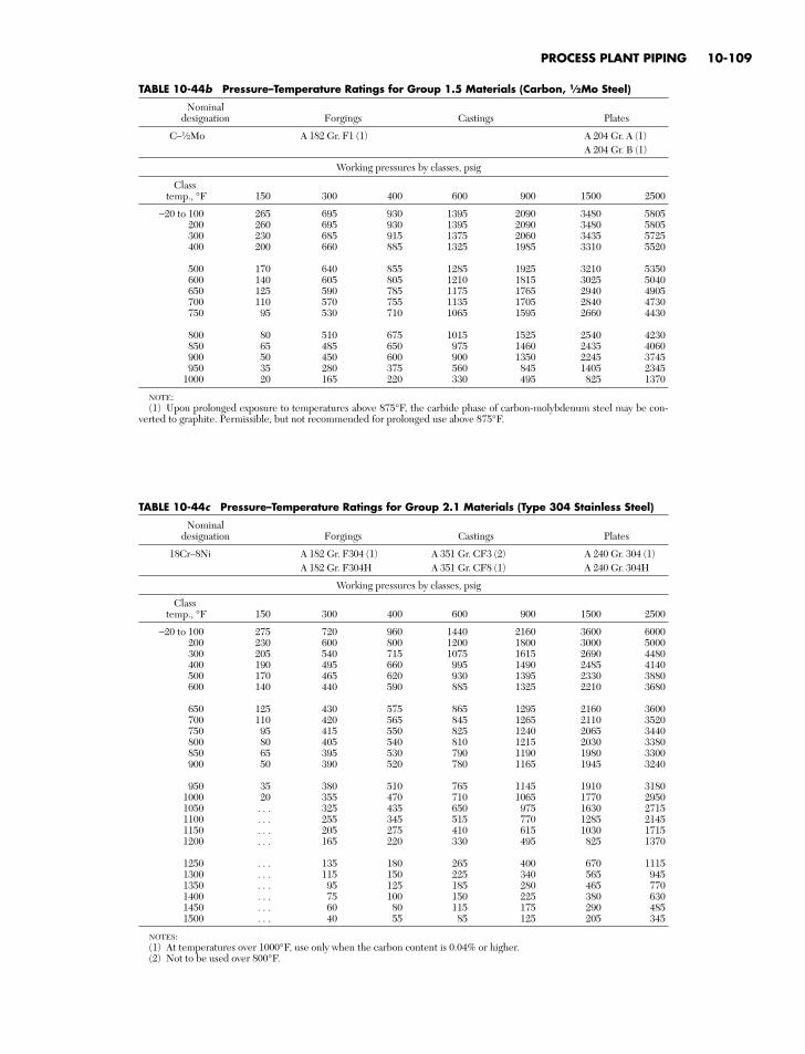
PROCESS PLANT PIPING 10-109
TABLE 10-44b Pressure–Temperature Ratings for Group 1.5 Materials (Carbon, 1⁄2Mo Steel)
Nominaldesignation Forgings Castings Plates
C–1⁄2Mo A 182 Gr. F1 (1) A 204 Gr. A (1)A 204 Gr. B (1)
Working pressures by classes, psig
Classtemp., °F 150 300 400 600 900 1500 2500
−20 to 100 265 695 930 1395 2090 3480 5805200 260 695 930 1395 2090 3480 5805300 230 685 915 1375 2060 3435 5725400 200 660 885 1325 1985 3310 5520
500 170 640 855 1285 1925 3210 5350600 140 605 805 1210 1815 3025 5040650 125 590 785 1175 1765 2940 4905700 110 570 755 1135 1705 2840 4730750 95 530 710 1065 1595 2660 4430
800 80 510 675 1015 1525 2540 4230850 65 485 650 975 1460 2435 4060900 50 450 600 900 1350 2245 3745950 35 280 375 560 845 1405 2345
1000 20 165 220 330 495 825 1370
NOTE:(1) Upon prolonged exposure to temperatures above 875°F, the carbide phase of carbon-molybdenum steel may be con-
verted to graphite. Permissible, but not recommended for prolonged use above 875°F.
TABLE 10-44c Pressure–Temperature Ratings for Group 2.1 Materials (Type 304 Stainless Steel)
Nominaldesignation Forgings Castings Plates
18Cr–8Ni A 182 Gr. F304 (1) A 351 Gr. CF3 (2) A 240 Gr. 304 (1)A 182 Gr. F304H A 351 Gr. CF8 (1) A 240 Gr. 304H
Working pressures by classes, psig
Classtemp., °F 150 300 400 600 900 1500 2500
−20 to 100 275 720 960 1440 2160 3600 6000200 230 600 800 1200 1800 3000 5000300 205 540 715 1075 1615 2690 4480400 190 495 660 995 1490 2485 4140500 170 465 620 930 1395 2330 3880600 140 440 590 885 1325 2210 3680
650 125 430 575 865 1295 2160 3600700 110 420 565 845 1265 2110 3520750 95 415 550 825 1240 2065 3440800 80 405 540 810 1215 2030 3380850 65 395 530 790 1190 1980 3300900 50 390 520 780 1165 1945 3240
950 35 380 510 765 1145 1910 31801000 20 355 470 710 1065 1770 29501050 . . . 325 435 650 975 1630 27151100 . . . 255 345 515 770 1285 21451150 . . . 205 275 410 615 1030 17151200 . . . 165 220 330 495 825 1370
1250 . . . 135 180 265 400 670 11151300 . . . 115 150 225 340 565 9451350 . . . 95 125 185 280 465 7701400 . . . 75 100 150 225 380 6301450 . . . 60 80 115 175 290 4851500 . . . 40 55 85 125 205 345
NOTES:(1) At temperatures over 1000°F, use only when the carbon content is 0.04% or higher.(2) Not to be used over 800°F.
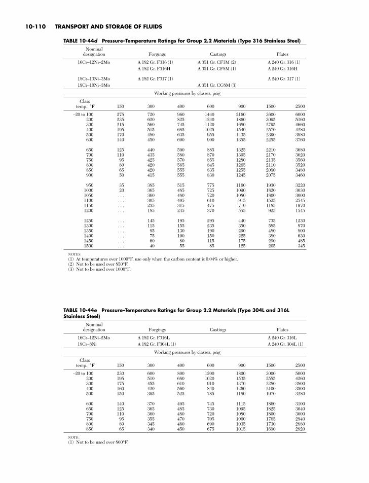
10-110 TRANSPORT AND STORAGE OF FLUIDS
TABLE 10-44d Pressure–Temperature Ratings for Group 2.2 Materials (Type 316 Stainless Steel)
Nominaldesignation Forgings Castings Plates
16Cr–12Ni–2Mo A 182 Gr. F316 (1) A 351 Gr. CF3M (2) A 240 Gr. 316 (1)A 182 Gr. F316H A 351 Gr. CF8M (1) A 240 Gr. 316H
18Cr–13Ni–3Mo A 182 Gr. F317 (1) A 240 Gr. 317 (1)19Cr–10Ni–3Mo A 351 Gr. CG8M (3)
Working pressures by classes, psig
Classtemp., °F 150 300 400 600 900 1500 2500
–20 to 100 275 720 960 1440 2160 3600 6000200 235 620 825 1240 1860 3095 5160300 215 560 745 1120 1680 2795 4660400 195 515 685 1025 1540 2570 4280500 170 480 635 955 1435 2390 3980600 140 450 600 900 1355 2255 3760
650 125 440 590 885 1325 2210 3680700 110 435 580 870 1305 2170 3620750 95 425 570 855 1280 2135 3560800 80 420 565 845 1265 2110 3520850 65 420 555 835 1255 2090 3480900 50 415 555 830 1245 2075 3460
950 35 385 515 775 1160 1930 32201000 20 365 485 725 1090 1820 30301050 . . . 360 480 720 1080 1800 30001100 . . . 305 405 610 915 1525 25451150 . . . 235 315 475 710 1185 19701200 . . . 185 245 370 555 925 1545
1250 . . . 145 195 295 440 735 12301300 . . . 115 155 235 350 585 9701350 . . . 95 130 190 290 480 8001400 . . . 75 100 150 225 380 6301450 . . . 60 80 115 175 290 4851500 . . . 40 55 85 125 205 345
NOTES:(1) At temperatures over 1000°F, use only when the carbon content is 0.04% or higher.(2) Not to be used over 850°F.(3) Not to be used over 1000°F.
TABLE 10-44e Pressure–Temperature Ratings for Group 2.2 Materials (Type 304L and 316LStainless Steel)
Nominaldesignation Forgings Castings Plates
16Cr–12Ni–2Mo A 182 Gr. F316L A 240 Gr. 316L18Cr–8Ni A 182 Gr. F304L (1) A 240 Gr. 304L (1)
Working pressures by classes, psig
Classtemp., °F 150 300 400 600 900 1500 2500
–20 to 100 230 600 800 1200 1800 3000 5000200 195 510 680 1020 1535 2555 4260300 175 455 610 910 1370 2280 3800400 160 420 560 840 1260 2100 3500500 150 395 525 785 1180 1970 3280
600 140 370 495 745 1115 1860 3100650 125 365 485 730 1095 1825 3040700 110 360 480 720 1080 1800 3000750 95 355 470 705 1060 1765 2940800 80 345 460 690 1035 1730 2880850 65 340 450 675 1015 1690 2820
NOTE:(1) Not to be used over 800°F.
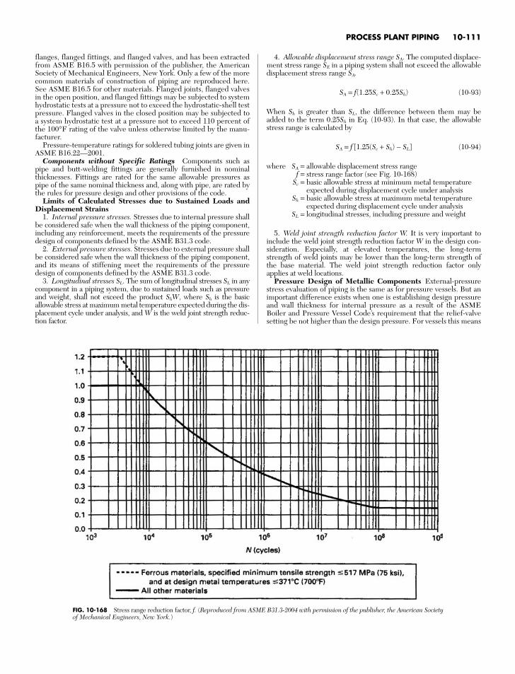
PROCESS PLANT PIPING 10-111
FIG. 10-168 Stress range reduction factor, f. (Reproduced from ASME B31.3-2004 with permission of the publisher, the American Societyof Mechanical Engineers, New York.)
flanges, flanged fittings, and flanged valves, and has been extractedfrom ASME B16.5 with permission of the publisher, the AmericanSociety of Mechanical Engineers, New York. Only a few of the morecommon materials of construction of piping are reproduced here.See ASME B16.5 for other materials. Flanged joints, flanged valvesin the open position, and flanged fittings may be subjected to systemhydrostatic tests at a pressure not to exceed the hydrostatic-shell testpressure. Flanged valves in the closed position may be subjected toa system hydrostatic test at a pressure not to exceed 110 percent ofthe 100°F rating of the valve unless otherwise limited by the manu-facturer.
Pressure-temperature ratings for soldered tubing joints are given inASME B16.22—2001.
Components without Specific Ratings Components such aspipe and butt-welding fittings are generally furnished in nominalthicknesses. Fittings are rated for the same allowable pressures aspipe of the same nominal thickness and, along with pipe, are rated bythe rules for pressure design and other provisions of the code.
Limits of Calculated Stresses due to Sustained Loads andDisplacement Strains
1. Internal pressure stresses. Stresses due to internal pressure shallbe considered safe when the wall thickness of the piping component,including any reinforcement, meets the requirements of the pressuredesign of components defined by the ASME B31.3 code.
2. External pressure stresses. Stresses due to external pressure shallbe considered safe when the wall thickness of the piping component,and its means of stiffening meet the requirements of the pressuredesign of components defined by the ASME B31.3 code.
3. Longitudinal stresses SL. The sum of longitudinal stresses SL in anycomponent in a piping system, due to sustained loads such as pressureand weight, shall not exceed the product ShW, where Sh is the basicallowable stress at maximum metal temperature expected during the dis-placement cycle under analysis, and W is the weld joint strength reduc-tion factor.
4. Allowable displacement stress range SA. The computed displace-ment stress range SE in a piping system shall not exceed the allowabledisplacement stress range SA.
SA = f(1.25Sc + 0.25Sh) (10-93)
When Sh is greater than SL, the difference between them may beadded to the term 0.25Sh in Eq. (10-93). In that case, the allowablestress range is calculated by
SA = f [1.25(Sc + Sh) − SL] (10-94)
where SA = allowable displacement stress rangef = stress range factor (see Fig. 10-168)
Sc = basic allowable stress at minimum metal temperatureexpected during displacement cycle under analysis
Sh = basic allowable stress at maximum metal temperatureexpected during displacement cycle under analysis
SL = longitudinal stresses, including pressure and weight
5. Weld joint strength reduction factor W. It is very important toinclude the weld joint strength reduction factor W in the design con-sideration. Especially, at elevated temperatures, the long-termstrength of weld joints may be lower than the long-term strength ofthe base material. The weld joint strength reduction factor onlyapplies at weld locations.
Pressure Design of Metallic Components External-pressurestress evaluation of piping is the same as for pressure vessels. But animportant difference exists when one is establishing design pressureand wall thickness for internal pressure as a result of the ASMEBoiler and Pressure Vessel Code’s requirement that the relief-valvesetting be not higher than the design pressure. For vessels this means

that the design is for a pressure 10 percent more or less above theintended maximum operating pressure to avoid popping or leakagefrom the valve during normal operation. However, on piping thedesign pressure and temperature are taken as the maximum intendedoperating pressure and coincident temperature combination whichresults in the maximum thickness. The temporary increased operat-ing conditions listed under “Design Criteria” cover temporary opera-tion at pressures that cause relief valves to leak or open fully.Allowable stresses for nearly 1000 materials are contained in thecode. For convenience, the allowable stresses for commonly usedcarbon and stainless steels have been extracted from the code andlisted in Table 10-44.
For straight metal pipe under internal pressure the formulafor minimum required wall thickness tm is applicable for:
1. t < D6. The internal pressure design thickness for straight pipeshall be not less than that calculated in accordance with the equationbelow. The more conservative Barlow and Lamé equations may alsobe used. Equation (10-95) includes a factor Y varying with materialand temperature to account for the redistribution of circumferential
stress which occurs under steady-state creep at high temperature andpermits slightly lesser thickness at this range.
tm = ÷ C (10-95)
where (in consistent units)P = design pressure
Do = outside diameter of pipeC = sum of allowances for corrosion, erosion, and any thread or
groove depth. For threaded components the depth is h ofASME B1.20.1, and for grooved components the depth isthe depth removed (0.02 in when no tolerance is specified).
SE = allowable stress (see Table 10-44)S = basic allowable stress for materials, excluding casting,
joint, or structural-grade quality factorsE = quality factor. The quality factor E is one or the product
of more than one of the following quality factors: castingquality factor Ec, joint quality factor Ej (see Fig. 10-169).
PDo2(SE + PY)
10-112 TRANSPORT AND STORAGE OF FLUIDS
Type of FactorNo. Type of Joint Seam Examination Ej
1 Furnace but weld, Straight As required by 0.60continuous weld listed specification [Note (1)]
2 Electric resistance Straight or As required by 0.85weld spiral listed specification [Note (1)]
3 Electric fusion weld
(a) Single butt weld Straight or As required by 0.80spiral listed specification
or this code
(with or without filler Additionally spot 0.90metal) radiographed per
para. 341.5.1,ASME B31.3
Additionally 100% 1.00radiographed perpara. 344.5.1 andTable 341.3.2,ASME B31.3
(b) Double butt weld Straight or spiral As required by 0.85[except as listed specificationprovided in 4(a) or this codebelow]
(with or without filler Additionally spot 0.90metal) radiographed per
para. 341.5.1,ASME B31.3
Additionally 100% 1.00radiographed perpara. 344.5.1 andTable 341.3.2,ASME B31.3
4 Per specific specification
(a) API 5L Submerged arc weld Straight with one As required by 0.95(SAW) or two seams specification
Gas metal arc weld Spiral(GMAW)
Combined GMAW,SAW
FIG. 10-169 Longitudinal weld joint quality factor, Ej. [NOTE (1): It is not permitted to increase the joint quality factor by additional examination for joint 1 or 2.](Reproduced from ASME B31.3 with permission of the publisher, the American Society of Mechanical Engineers, New York.)
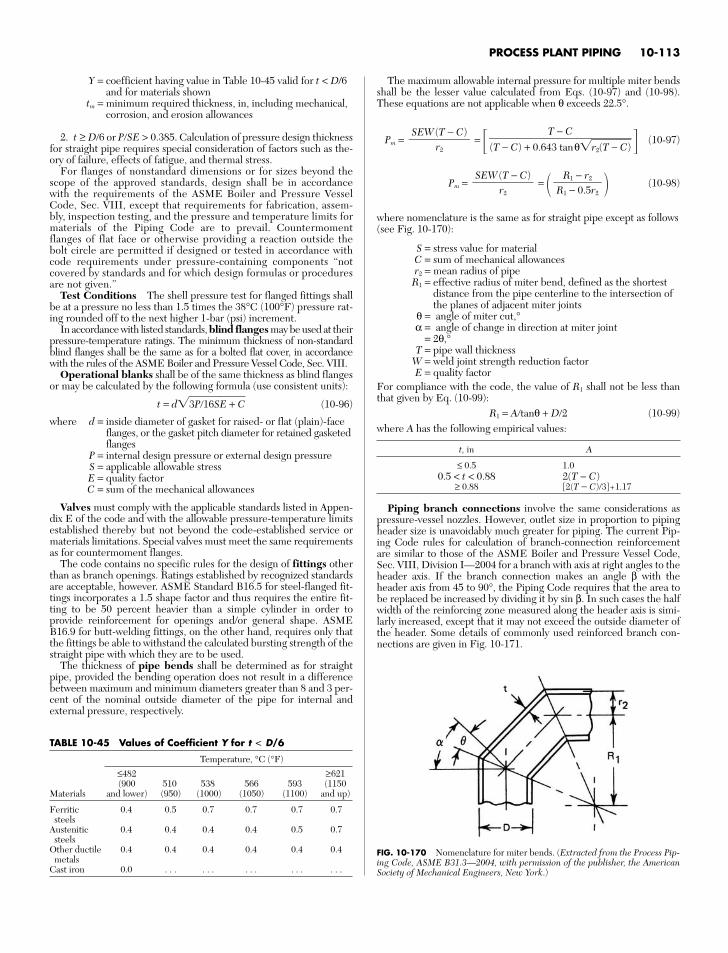
Y = coefficient having value in Table 10-45 valid for t < D/6and for materials shown
tm = minimum required thickness, in, including mechanical,corrosion, and erosion allowances
2. t ≥ D6 or PSE > 0.385. Calculation of pressure design thicknessfor straight pipe requires special consideration of factors such as the-ory of failure, effects of fatigue, and thermal stress.
For flanges of nonstandard dimensions or for sizes beyond thescope of the approved standards, design shall be in accordancewith the requirements of the ASME Boiler and Pressure VesselCode, Sec. VIII, except that requirements for fabrication, assem-bly, inspection testing, and the pressure and temperature limits formaterials of the Piping Code are to prevail. Countermomentflanges of flat face or otherwise providing a reaction outside thebolt circle are permitted if designed or tested in accordance withcode requirements under pressure-containing components “notcovered by standards and for which design formulas or proceduresare not given.”
Test Conditions The shell pressure test for flanged fittings shallbe at a pressure no less than 1.5 times the 38°C (100°F) pressure rat-ing rounded off to the next higher 1-bar (psi) increment.
In accordance with listed standards, blind flanges may be used at theirpressure-temperature ratings. The minimum thickness of non-standardblind flanges shall be the same as for a bolted flat cover, in accordancewith the rules of the ASME Boiler and Pressure Vessel Code, Sec. VIII.
Operational blanks shall be of the same thickness as blind flangesor may be calculated by the following formula (use consistent units):
t = d3P16SE + C (10-96)
where d = inside diameter of gasket for raised- or flat (plain)-faceflanges, or the gasket pitch diameter for retained gasketedflanges
P = internal design pressure or external design pressureS = applicable allowable stressE = quality factorC = sum of the mechanical allowances
Valves must comply with the applicable standards listed in Appen-dix E of the code and with the allowable pressure-temperature limitsestablished thereby but not beyond the code-established service ormaterials limitations. Special valves must meet the same requirementsas for countermoment flanges.
The code contains no specific rules for the design of fittings otherthan as branch openings. Ratings established by recognized standardsare acceptable, however. ASME Standard B16.5 for steel-flanged fit-tings incorporates a 1.5 shape factor and thus requires the entire fit-ting to be 50 percent heavier than a simple cylinder in order toprovide reinforcement for openings and/or general shape. ASMEB16.9 for butt-welding fittings, on the other hand, requires only thatthe fittings be able to withstand the calculated bursting strength of thestraight pipe with which they are to be used.
The thickness of pipe bends shall be determined as for straightpipe, provided the bending operation does not result in a differencebetween maximum and minimum diameters greater than 8 and 3 per-cent of the nominal outside diameter of the pipe for internal andexternal pressure, respectively.
The maximum allowable internal pressure for multiple miter bendsshall be the lesser value calculated from Eqs. (10-97) and (10-98).These equations are not applicable when θ exceeds 22.5°.
Pm = = (10-97)
Pm = = (10-98)
where nomenclature is the same as for straight pipe except as follows(see Fig. 10-170):
S = stress value for materialC = sum of mechanical allowancesr2 = mean radius of pipeR1 = effective radius of miter bend, defined as the shortest
distance from the pipe centerline to the intersection ofthe planes of adjacent miter joints
θ = angle of miter cut,°α = angle of change in direction at miter joint
= 2θ,°T = pipe wall thickness
W = weld joint strength reduction factorE = quality factor
For compliance with the code, the value of R1 shall not be less thanthat given by Eq. (10-99):
R1 = Atanθ + D2 (10-99)where A has the following empirical values:
t, in A
≤ 0.5 1.00.5 < t < 0.88 2(T − C)
≥ 0.88 [2(T − C)/3]+1.17
Piping branch connections involve the same considerations aspressure-vessel nozzles. However, outlet size in proportion to pipingheader size is unavoidably much greater for piping. The current Pip-ing Code rules for calculation of branch-connection reinforcementare similar to those of the ASME Boiler and Pressure Vessel Code,Sec. VIII, Division I—2004 for a branch with axis at right angles to theheader axis. If the branch connection makes an angle β with theheader axis from 45 to 90°, the Piping Code requires that the area tobe replaced be increased by dividing it by sin β. In such cases the halfwidth of the reinforcing zone measured along the header axis is simi-larly increased, except that it may not exceed the outside diameter ofthe header. Some details of commonly used reinforced branch con-nections are given in Fig. 10-171.
R1 − r2R1 − 0.5r2
SEW(T − C)
r2
T − C(T − C) + 0.643 tanθr2(T −C)
SEW(T − C)
r2
PROCESS PLANT PIPING 10-113
TABLE 10-45 Values of Coefficient Y for t < D/6
Temperature, °C (°F)
≤482 ≥621(900 510 538 566 593 (1150
Materials and lower) (950) (1000) (1050) (1100) and up)
Ferritic 0.4 0.5 0.7 0.7 0.7 0.7steels
Austenitic 0.4 0.4 0.4 0.4 0.5 0.7steels
Other ductile 0.4 0.4 0.4 0.4 0.4 0.4metals
Cast iron 0.0 . . . . . . . . . . . . . . .
FIG. 10-170 Nomenclature for miter bends. (Extracted from the Process Pip-ing Code, ASME B31.3—2004, with permission of the publisher, the AmericanSociety of Mechanical Engineers, New York.)
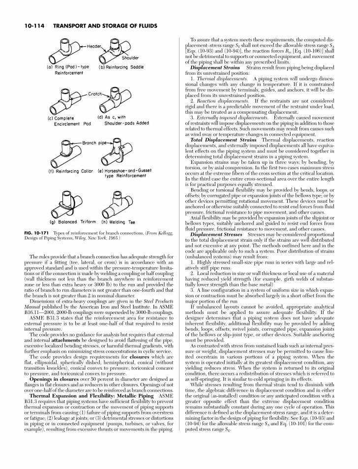
The rules provide that a branch connection has adequate strength forpressure if a fitting (tee, lateral, or cross) is in accordance with anapproved standard and is used within the pressure-temperature limita-tions or if the connection is made by welding a coupling or half coupling(wall thickness not less than the branch anywhere in reinforcementzone or less than extra heavy or 3000 lb) to the run and provided theratio of branch to run diameters is not greater than one-fourth and thatthe branch is not greater than 2 in nominal diameter.
Dimensions of extra-heavy couplings are given in the Steel ProductsManual published by the American Iron and Steel Institute. In ASMEB16.11—2001, 2000-lb couplings were superseded by 3000-lb couplings.
ASME B31.3 states that the reinforcement area for resistance toexternal pressure is to be at least one-half of that required to resistinternal pressure.
The code provides no guidance for analysis but requires that externaland internal attachments be designed to avoid flattening of the pipe,excessive localized bending stresses, or harmful thermal gradients, withfurther emphasis on minimizing stress concentrations in cyclic service.
The code provides design requirements for closures which areflat, ellipsoidal, spherically dished, hemispherical, conical (withouttransition knuckles), conical convex to pressure, toriconical concaveto pressure, and toriconical convex to pressure.
Openings in closures over 50 percent in diameter are designed asflanges in flat closures and as reducers in other closures. Openings of notover one-half of the diameter are to be reinforced as branch connections.
Thermal Expansion and Flexibility: Metallic Piping ASMEB31.3 requires that piping systems have sufficient flexibility to preventthermal expansion or contraction or the movement of piping supportsor terminals from causing (1) failure of piping supports from overstressor fatigue; (2) leakage at joints; or (3) detrimental stresses or distortionsin piping or in connected equipment (pumps, turbines, or valves, forexample), resulting from excessive thrusts or movements in the piping.
To assure that a system meets these requirements, the computed dis-placement–stress range SE shall not exceed the allowable stress range SA
[Eqs. (10-93) and (10-94)], the reaction forces Rm [Eq. (10-106)] shallnot be detrimental to supports or connected equipment, and movementof the piping shall be within any prescribed limits.
Displacement Strains Strains result from piping being displacedfrom its unrestrained position:
1. Thermal displacements. A piping system will undergo dimen-sional changes with any change in temperature. If it is constrainedfrom free movement by terminals, guides, and anchors, it will be dis-placed from its unrestrained position.
2. Reaction displacements. If the restraints are not consideredrigid and there is a predictable movement of the restraint under load,this may be treated as a compensating displacement.
3. Externally imposed displacements. Externally caused movementof restraints will impose displacements on the piping in addition to thoserelated to thermal effects. Such movements may result from causes suchas wind sway or temperature changes in connected equipment.
Total Displacement Strains Thermal displacements, reactiondisplacements, and externally imposed displacements all have equiva-lent effects on the piping system and must be considered together indetermining total displacement strains in a piping system.
Expansion strains may be taken up in three ways: by bending, bytorsion, or by axial compression. In the first two cases maximum stressoccurs at the extreme fibers of the cross section at the critical location.In the third case the entire cross-sectional area over the entire lengthis for practical purposes equally stressed.
Bending or torsional flexibility may be provided by bends, loops, oroffsets; by corrugated pipe or expansion joints of the bellows type; or byother devices permitting rotational movement. These devices must beanchored or otherwise suitably connected to resist end forces from fluidpressure, frictional resistance to pipe movement, and other causes.
Axial flexibility may be provided by expansion joints of the slipjoint orbellows types, suitably anchored and guided to resist end forces fromfluid pressure, frictional resistance to movement, and other causes.
Displacement Stresses Stresses may be considered proportionalto the total displacement strain only if the strains are well distributedand not excessive at any point. The methods outlined here and in thecode are applicable only to such a system. Poor distribution of strains(unbalanced systems) may result from:
1. Highly stressed small-size pipe runs in series with large and rel-atively stiff pipe runs
2. Local reduction in size or wall thickness or local use of a materialhaving reduced yield strength (for example, girth welds of substan-tially lower strength than the base metal)
3. A line configuration in a system of uniform size in which expan-sion or contraction must be absorbed largely in a short offset from themajor portion of the run
If unbalanced layouts cannot be avoided, appropriate analyticalmethods must be applied to assure adequate flexibility. If thedesigner determines that a piping system does not have adequateinherent flexibility, additional flexibility may be provided by addingbends, loops, offsets, swivel joints, corrugated pipe, expansion jointsof the bellows or slip-joint type, or other devices. Suitable anchoringmust be provided.
As contrasted with stress from sustained loads such as internal pres-sure or weight, displacement stresses may be permitted to cause lim-ited overstrain in various portions of a piping system. When thesystem is operated initially at its greatest displacement condition, anyyielding reduces stress. When the system is returned to its originalcondition, there occurs a redistribution of stresses which is referred toas self-springing. It is similar to cold springing in its effects.
While stresses resulting from thermal strain tend to diminish withtime, the algebraic difference in displacement condition and in eitherthe original (as-installed) condition or any anticipated condition with agreater opposite effect than the extreme displacement conditionremains substantially constant during any one cycle of operation. Thisdifference is defined as the displacement-stress range, and it is a deter-mining factor in the design of piping for flexibility. See Eqs. (10-93) and(10-94) for the allowable stress range SA and Eq. (10-101) for the com-puted stress range SE.
10-114 TRANSPORT AND STORAGE OF FLUIDS
FIG. 10-171 Types of reinforcement for branch connections. (From Kellogg,Design of Piping Systems, Wiley, New York, 1965.)
Cold Spring Cold spring is the intentional deformation of pipingduring assembly to produce a desired initial displacement and stress.For pipe operating at a temperature higher than that at which it wasinstalled, cold spring is accomplished by fabricating it slightly shorterthan design length. Cold spring is beneficial in that it serves to balancethe magnitude of stress under initial and extreme displacement condi-tions. When cold spring is properly applied, there is less likelihood ofoverstrain during initial operation; hence, it is recommended espe-cially for piping materials of limited ductility. There is also less devia-tion from as-installed dimensions during initial operation, so thathangers will not be displaced as far from their original settings.
Inasmuch as the service life of a system is affected more by the rangeof stress variation than by the magnitude of stress at a given time, nocredit for cold spring is permitted in stress-range calculations. However,in calculating the thrusts and moments when actual reactions as well astheir range of variations are significant, credit is given for cold spring.
Values of thermal-expansion coefficients to be used in determiningtotal displacement strains for computing the stress range are deter-mined from Table 10-46 as the algebraic difference between the valueat design maximum temperature and that at the design minimumtemperature for the thermal cycle under analysis.
Values for Reactions Values of thermal displacements to beused in determining total displacement strains for the computation ofreactions on supports and connected equipment shall be determinedas the algebraic difference between the value at design maximum (orminimum) temperature for the thermal cycle under analysis and thevalue at the temperature expected during installation.
The as-installed and maximum or minimum moduli of elasticity, Ea
and Em respectively, shall be taken as the values shown in Table 10-47.Poisson’s ratio may be taken as 0.3 at all temperatures for all metals.The allowable stress range for displacement stresses SA and permis-
sible additive stresses shall be as specified in Eqs. (10-93) and (10-94)for systems primarily stressed in bending and/or torsion. For pipe orpiping components containing longitudinal welds the basic allowablestress S may be used to determine SA.
Nominal thicknesses and outside diameters of pipe and fittings shallbe used in flexibility calculations.
In the absence of more directly applicable data, the flexibility factor kand stress-intensification factor i shown in Table 10-48 may be used inflexibility calculations in Eq. (10-102). For piping components or attach-ments (such as valves, strainers, anchor rings, and bands) not covered inthe table, suitable stress-intensification factors may be assumed by com-parison of their significant geometry with that of the components shown.
Requirements for Analysis No formal analysis of adequate flexi-bility is required in systems which (1) are duplicates of successfully oper-ating installations or replacements without significant change of systemswith a satisfactory service record; (2) can readily be judged adequate bycomparison with previously analyzed systems; or (3) are of uniform size,have no more than two points of fixation, have no intermediate restraints,and fall within the limitations of empirical Eq. (10-100):*
≤ K1 (10-100)
where D = ouside diameter of pipe, in (mm)y = resultant of total displacement strains, in (mm), to be
absorbed by the piping systemL = developed length of piping between anchors, ft (m)U = anchor distance, straight line between anchors, ft (m)
K1 = 0.03 for U.S. customary units listed= 208.3 for SI units listed in parentheses
Dy(L − U)2
1. All systems not meeting these criteria shall be analyzed by sim-plified, approximate, or comprehensive methods of analysis appropri-ate for the specific case.
2. Approximate or simplified methods may be applied only if theyare used in the range of configurations for which their adequacy hasbeen demonstrated.
3. Acceptable comprehensive methods of analysis include analyti-cal and chart methods which provide an evaluation of the forces,moments, and stresses caused by displacement strains.
4. Comprehensive analysis shall take into account stress-intensifi-cation factors for any component other than straight pipe. Credit maybe taken for the extra flexibility of such a component.
In calculating the flexibility of a piping system between anchorpoints, the system shall be treated as a whole. The significance of allparts of the line and of all restraints introduced for the purpose ofreducing moments and forces on equipment or small branch lines andalso the restraint introduced by support friction shall be recognized.Consider all displacements over the temperature range defined byoperating and shutdown conditions.
Flexibility Stresses Bending and torsional stresses shall be com-puted using the as-installed modulus of elasticity Ea and then com-bined in accordance with Eq. (10-101) to determine the computeddisplacement stress range SE, which shall not exceed the allowablestress range SA [Eqs. (10-93) and (10-94)]:
SE = S2b + 4St
2 (10-101)
where Sb = resultant bending stress, lbf/in2 (MPa)St = Mt/2Z = torsional stress, lbf/in2 (MPa)
Mt = torsional moment, in⋅lbf (N⋅mm)Z = section modulus of pipe, in3 (mm3)
The resultant bending stresses Sb to be used in Eq. (10-101) forelbows and miter bends shall be calculated in accordance with Eq.(10-102), with moments as shown in Fig. (10-172):
Sb = (10-102)
where Sb = resultant bending stress, lbf/in2 (MPa)ii = in-plane stress-intensification factor from Table 10-48io = out-plane stress-intensification factor from Table 10-48
Mi = in-plane bending moment, in⋅lbf (N⋅mm)Mo = out-plane bending moment, in⋅lbf (N⋅mm)
Z = section modulus of pipe, in3 (mm3)
The resultant bending stresses Sb to be used in Eq. (10-101) forbranch connections shall be calculated in accordance with Eqs. (10-103) and (10-104), with moments as shown in Fig. 10-173.
For header (legs 1 and 2):
Sb = (10-103)
For branch (leg 3):
Sb = (10-104)
where Sb = resultant bending stress, lbf/in2 (MPa)Ze = effective section modulus for branch, in3 (mm3)
Ze = πr22TS (10-105)
r2 = mean branch cross-sectional radius, in (mm)Ts = effective branch wall thickness, in (mm) [lesser of T
⎯h
and (io) (T⎯
b)]T⎯
h = thickness of pipe matching run of tee or header exclu-sive of reinforcing elements, in (mm)
(iiMi)2+ (ioMo)2
Ze
(iiMi)2+ (ioMo)2
Z
(iiMi)2+ (ioMo)2
Z
PROCESS PLANT PIPING 10-115
*WARNING: No general proof can be offered that this equation will yieldaccurate or consistently conservative results. It is not applicable to systems usedunder severe cyclic conditions. It should be used with caution in configurationssuch as unequal leg U bends (LU > 2.5) or near-straight sawtooth runs, or forlarge thin-wall pipe (i ≥ 5), or when extraneous displacements (not in the direc-tion connecting anchor points) constitute a large part of the total displacement.There is no assurance that terminal reactions will be acceptably low even if apiping system falls within the limitations of Eq. (10-100).
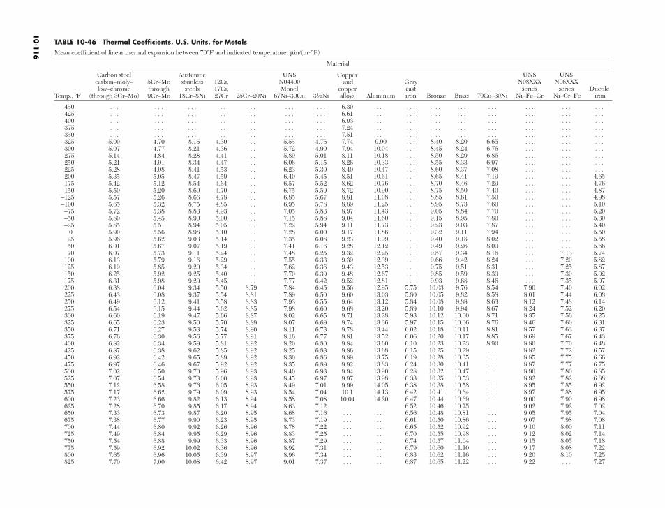
TABLE 10-46 Thermal Coefficients, U.S. Units, for Metals Mean coefficient of linear thermal expansion between 70°F and indicated temperature, µin/(in°F)
Material
Carbon steel Austenitic UNS Coppercarbon–moly– 5Cr–Mo stainless 12Cr, N04400 and low–chrome through steels 17Cr, Monel copper
Temp., ºF (through 3Cr–Mo) 9Cr–Mo 18Cr–8Ni 27Cr 25Cr–20Ni 67Ni–30Cu 31⁄2Ni alloys
−450 . . . . . . . . . . . . . . . . . . . . . 6.30−425 . . . . . . . . . . . . . . . . . . . . . 6.61−400 . . . . . . . . . . . . . . . . . . . . . 6.93−375 . . . . . . . . . . . . . . . . . . . . . 7.24−350 . . . . . . . . . . . . . . . . . . . . . 7.51−325 5.00 4.70 8.15 4.30 . . . 5.55 4.76 7.74−300 5.07 4.77 8.21 4.36 . . . 5.72 4.90 7.94−275 5.14 4.84 8.28 4.41 . . . 5.89 5.01 8.11−250 5.21 4.91 8.34 4.47 . . . 6.06 5.15 8.26−225 5.28 4.98 8.41 4.53 . . . 6.23 5.30 8.40−200 5.35 5.05 8.47 4.59 . . . 6.40 5.45 8.51−175 5.42 5.12 8.54 4.64 . . . 6.57 5.52 8.62−150 5.50 5.20 8.60 4.70 . . . 6.75 5.59 8.72−125 5.57 5.26 8.66 4.78 . . . 6.85 5.67 8.81−100 5.65 5.32 8.75 4.85 . . . 6.95 5.78 8.89−75 5.72 5.38 8.83 4.93 . . . 7.05 5.83 8.97−50 5.80 5.45 8.90 5.00 . . . 7.15 5.88 9.04−25 5.85 5.51 8.94 5.05 . . . 7.22 5.94 9.11
0 5.90 5.56 8.98 5.10 . . . 7.28 6.00 9.1725 5.96 5.62 9.03 5.14 . . . 7.35 6.08 9.2350 6.01 5.67 9.07 5.19 . . . 7.41 6.16 9.2870 6.07 5.73 9.11 5.24 . . . 7.48 6.25 9.32
100 6.13 5.79 9.16 5.29 . . . 7.55 6.33 9.39125 6.19 5.85 9.20 5.34 . . . 7.62 6.36 9.43150 6.25 5.92 9.25 5.40 . . . 7.70 6.39 9.48175 6.31 5.98 9.29 5.45 . . . 7.77 6.42 9.52200 6.38 6.04 9.34 5.50 8.79 7.84 6.45 9.56225 6.43 6.08 9.37 5.54 8.81 7.89 6.50 9.60250 6.49 6.12 9.41 5.58 8.83 7.93 6.55 9.64275 6.54 6.15 9.44 5.62 8.85 7.98 6.60 9.68300 6.60 6.19 9.47 5.66 8.87 8.02 6.65 9.71325 6.65 6.23 9.50 5.70 8.89 8.07 6.69 9.74350 6.71 6.27 9.53 5.74 8.90 8.11 6.73 9.78375 6.76 6.30 9.56 5.77 8.91 8.16 6.77 9.81400 6.82 6.34 9.59 5.81 8.92 8.20 6.80 9.84425 6.87 6.38 9.62 5.85 8.92 8.25 6.83 9.86450 6.92 6.42 9.65 5.89 8.92 8.30 6.86 9.89475 6.97 6.46 9.67 5.92 8.92 8.35 6.89 9.92500 7.02 6.50 9.70 5.96 8.93 8.40 6.93 9.94525 7.07 6.54 9.73 6.00 8.93 8.45 6.97 9.97550 7.12 6.58 9.76 6.05 8.93 8.49 7.01 9.99575 7.17 6.62 9.79 6.09 8.93 8.54 7.04 10.1600 7.23 6.66 9.82 6.13 8.94 8.58 7.08 10.04625 7.28 6.70 9.85 6.17 8.94 8.63 7.12 . . .650 7.33 6.73 9.87 6.20 8.95 8.68 7.16 . . .675 7.38 6.77 9.90 6.23 8.95 8.73 7.19 . . .700 7.44 6.80 9.92 6.26 8.96 8.78 7.22 . . .725 7.49 6.84 9.95 6.29 8.96 8.83 7.25 . . .750 7.54 6.88 9.99 6.33 8.96 8.87 7.29 . . .775 7.59 6.92 10.02 6.36 8.96 8.92 7.31 . . .800 7.65 6.96 10.05 6.39 8.97 8.96 7.34 . . .825 7.70 7.00 10.08 6.42 8.97 9.01 7.37 . . .
UNS UNSGray N08XXX N06XXXcast series series Ductile
Aluminum iron Bronze Brass 70Cu–30Ni Ni–Fe–Cr Ni–Cr–Fe iron
. . . . . . . . . . . . . . . . . . . . . . . .
. . . . . . . . . . . . . . . . . . . . . . . .
. . . . . . . . . . . . . . . . . . . . . . . .
. . . . . . . . . . . . . . . . . . . . . . . .
. . . . . . . . . . . . . . . . . . . . . . . .9.90 . . . 8.40 8.20 6.65 . . . . . . . . .10.04 . . . 8.45 8.24 6.76 . . . . . . . . .10.18 . . . 8.50 8.29 6.86 . . . . . . . . .10.33 . . . 8.55 8.33 6.97 . . . . . . . . .10.47 . . . 8.60 8.37 7.08 . . . . . . . . .10.61 . . . 8.65 8.41 7.19 . . . . . . 4.6510.76 . . . 8.70 8.46 7.29 . . . . . . 4.7610.90 . . . 8.75 8.50 7.40 . . . . . . 4.8711.08 . . . 8.85 8.61 7.50 . . . . . . 4.9811.25 . . . 8.95 8.73 7.60 . . . . . . 5.1011.43 . . . 9.05 8.84 7.70 . . . . . . 5.2011.60 . . . 9.15 8.95 7.80 . . . . . . 5.3011.73 . . . 9.23 9.03 7.87 . . . . . . 5.4011.86 . . . 9.32 9.11 7.94 . . . . . . 5.5011.99 . . . 9.40 9.18 8.02 . . . . . . 5.5812.12 . . . 9.49 9.26 8.09 . . . . . . 5.6612.25 . . . 9.57 9.34 8.16 . . . 7.13 5.7412.39 . . . 9.66 9.42 8.24 . . . 7.20 5.8212.53 . . . 9.75 9.51 8.31 . . . 7.25 5.8712.67 . . . 9.85 9.59 8.39 . . . 7.30 5.9212.81 . . . 9.93 9.68 8.46 . . . 7.35 5.9712.95 5.75 10.03 9.76 8.54 7.90 7.40 6.0213.03 5.80 10.05 9.82 8.58 8.01 7.44 6.0813.12 5.84 10.08 9.88 8.63 8.12 7.48 6.1413.20 5.89 10.10 9.94 8.67 8.24 7.52 6.2013.28 5.93 10.12 10.00 8.71 8.35 7.56 6.2513.36 5.97 10.15 10.06 8.76 8.46 7.60 6.3113.44 6.02 10.18 10.11 8.81 8.57 7.63 6.3713.52 6.06 10.20 10.17 8.85 8.69 7.67 6.4313.60 6.10 10.23 10.23 8.90 8.80 7.70 6.4813.68 6.15 10.25 10.29 . . . 8.82 7.72 6.5713.75 6.19 10.28 10.35 . . . 8.85 7.75 6.6613.83 6.24 10.30 10.41 . . . 8.87 7.77 6.7513.90 6.28 10.32 10.47 . . . 8.90 7.80 6.8513.98 6.33 10.35 10.53 . . . 8.92 7.82 6.8814.05 6.38 10.38 10.58 . . . 8.95 7.85 6.9214.13 6.42 10.41 10.64 . . . 8.97 7.88 6.9514.20 6.47 10.44 10.69 . . . 9.00 7.90 6.98. . . 6.52 10.46 10.75 . . . 9.02 7.92 7.02. . . 6.56 10.48 10.81 . . . 9.05 7.95 7.04. . . 6.61 10.50 10.86 . . . 9.07 7.98 7.08. . . 6.65 10.52 10.92 . . . 9.10 8.00 7.11. . . 6.70 10.55 10.98 . . . 9.12 8.02 7.14. . . 6.74 10.57 11.04 . . . 9.15 8.05 7.18. . . 6.79 10.60 11.10 . . . 9.17 8.08 7.22. . . 6.83 10.62 11.16 . . . 9.20 8.10 7.25. . . 6.87 10.65 11.22 . . . 9.22 . . . 7.27
10
-11
6
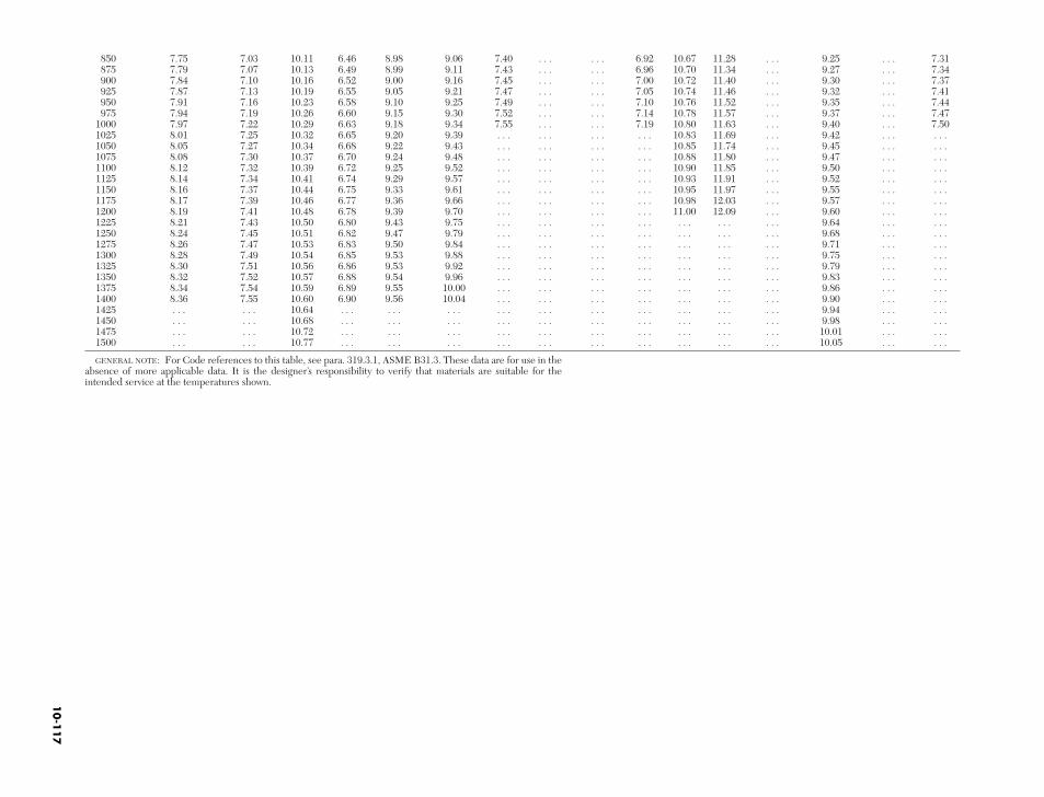
850 7.75 7.03 10.11 6.46 8.98 9.06 7.40 . . .875 7.79 7.07 10.13 6.49 8.99 9.11 7.43 . . .900 7.84 7.10 10.16 6.52 9.00 9.16 7.45 . . .925 7.87 7.13 10.19 6.55 9.05 9.21 7.47 . . .950 7.91 7.16 10.23 6.58 9.10 9.25 7.49 . . .975 7.94 7.19 10.26 6.60 9.15 9.30 7.52 . . .
1000 7.97 7.22 10.29 6.63 9.18 9.34 7.55 . . .1025 8.01 7.25 10.32 6.65 9.20 9.39 . . . . . .1050 8.05 7.27 10.34 6.68 9.22 9.43 . . . . . .1075 8.08 7.30 10.37 6.70 9.24 9.48 . . . . . .1100 8.12 7.32 10.39 6.72 9.25 9.52 . . . . . .1125 8.14 7.34 10.41 6.74 9.29 9.57 . . . . . .1150 8.16 7.37 10.44 6.75 9.33 9.61 . . . . . .1175 8.17 7.39 10.46 6.77 9.36 9.66 . . . . . .1200 8.19 7.41 10.48 6.78 9.39 9.70 . . . . . .1225 8.21 7.43 10.50 6.80 9.43 9.75 . . . . . .1250 8.24 7.45 10.51 6.82 9.47 9.79 . . . . . .1275 8.26 7.47 10.53 6.83 9.50 9.84 . . . . . .1300 8.28 7.49 10.54 6.85 9.53 9.88 . . . . . .1325 8.30 7.51 10.56 6.86 9.53 9.92 . . . . . .1350 8.32 7.52 10.57 6.88 9.54 9.96 . . . . . .1375 8.34 7.54 10.59 6.89 9.55 10.00 . . . . . .1400 8.36 7.55 10.60 6.90 9.56 10.04 . . . . . .1425 . . . . . . 10.64 . . . . . . . . . . . . . . .1450 . . . . . . 10.68 . . . . . . . . . . . . . . .1475 . . . . . . 10.72 . . . . . . . . . . . . . . .1500 . . . . . . 10.77 . . . . . . . . . . . . . . .
GENERAL NOTE: For Code references to this table, see para. 319.3.1, ASME B31.3. These data are for use in theabsence of more applicable data. It is the designer’s responsibility to verify that materials are suitable for theintended service at the temperatures shown.
. . . 6.92 10.67 11.28 . . . 9.25 . . . 7.31
. . . 6.96 10.70 11.34 . . . 9.27 . . . 7.34
. . . 7.00 10.72 11.40 . . . 9.30 . . . 7.37
. . . 7.05 10.74 11.46 . . . 9.32 . . . 7.41
. . . 7.10 10.76 11.52 . . . 9.35 . . . 7.44
. . . 7.14 10.78 11.57 . . . 9.37 . . . 7.47
. . . 7.19 10.80 11.63 . . . 9.40 . . . 7.50
. . . . . . 10.83 11.69 . . . 9.42 . . . . . .
. . . . . . 10.85 11.74 . . . 9.45 . . . . . .
. . . . . . 10.88 11.80 . . . 9.47 . . . . . .
. . . . . . 10.90 11.85 . . . 9.50 . . . . . .
. . . . . . 10.93 11.91 . . . 9.52 . . . . . .
. . . . . . 10.95 11.97 . . . 9.55 . . . . . .
. . . . . . 10.98 12.03 . . . 9.57 . . . . . .
. . . . . . 11.00 12.09 . . . 9.60 . . . . . .
. . . . . . . . . . . . . . . 9.64 . . . . . .
. . . . . . . . . . . . . . . 9.68 . . . . . .
. . . . . . . . . . . . . . . 9.71 . . . . . .
. . . . . . . . . . . . . . . 9.75 . . . . . .
. . . . . . . . . . . . . . . 9.79 . . . . . .
. . . . . . . . . . . . . . . 9.83 . . . . . .
. . . . . . . . . . . . . . . 9.86 . . . . . .
. . . . . . . . . . . . . . . 9.90 . . . . . .
. . . . . . . . . . . . . . . 9.94 . . . . . .
. . . . . . . . . . . . . . . 9.98 . . . . . .
. . . . . . . . . . . . . . . 10.01 . . . . . .
. . . . . . . . . . . . . . . 10.05 . . . . . .
10
-11
7
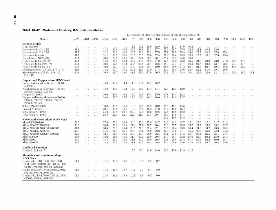
TABLE 10-47 Modulus of Elasticity, U.S. Units, for Metals
E = modulus of elasticity, Msi (millions of psi), at temperature, °F
Material –425 –400 –350 –325 –200 –100 70 200 300 400
Ferrous MetalsGray cast iron . . . . . . . . . . . . . . . . . . 13.4 13.2 12.9 12.6Carbon steels, C ≤ 0.3% 31.9 . . . . . . 31.4 30.8 30.2 29.5 28.8 28.3 27.7Carbon steels, C ≤ 0.3% 31.7 . . . . . . 31.2 30.6 30.0 29.3 28.6 28.1 27.5Carbon-moly steels 31.7 . . . . . . 31.1 30.5 29.9 29.2 28.5 28.0 27.4Nickel steels, Ni 2%–9% 30.1 . . . . . . 29.6 29.1 28.5 27.8 27.1 26.7 26.1Cr-Mo steels, Cr 1⁄2%–2% 32.1 . . . . . . 31.6 31.0 30.4 29.7 29.0 28.5 27.9Cr-Mo steels, Cr 21⁄4%–3% 33.1 . . . . . . 32.6 32.0 31.4 30.6 29.8 29.4 28.8Cr-Mo steels, Cr 5%–9% 33.4 . . . . . . 32.9 32.3 31.7 30.9 30.1 29.7 29.0Chromium steels, Cr 12%, 17%, 27% 31.8 . . . . . . 31.2 30.7 30.1 29.2 28.5 27.9 27.3Austenitic steels (TP304, 310, 316, 30.8 . . . . . . 30.3 29.7 29.0 28.3 27.6 27.0 26.5321, 347)
Copper and Copper Alloys (UNS Nos.)Comp. and leaded Sn-bronze (C83600, . . . . . . . . . 14.8 14.6 14.4 14.0 13.7 13.4 13.2C92200)
Naval brass, Si- & Al-bronze (C46400, . . . . . . . . . 15.9 15.6 15.4 15.0 14.6 14.4 14.1C65500, C95200, C95400)
Copper (C11000) . . . . . . . . . 16.9 16.6 16.5 16.0 15.6 15.4 15.0Copper, red brass, Al-bronze (C10200, . . . . . . . . . 18.0 17.7 17.5 17.0 16.6 16.3 16.0C12000, C12200, C12500, C14200, C23000, C61400)
90Cu 10Ni (C70600) . . . . . . . . . 19.0 18.7 18.5 18.0 17.6 17.3 16.9Leaded Ni-bronze . . . . . . . . . 20.1 19.8 19.6 19.0 18.5 18.2 17.980Cu-20Ni (C71000) . . . . . . . . . 21.2 20.8 20.6 20.0 19.5 19.2 18.870Cu-30Ni (C71500) . . . . . . . . . 23.3 22.9 22.7 22.0 21.5 21.1 20.7
Nickel and Nickel Alloys (UNS Nos.)Monel 400 N04400 28.3 . . . . . . 27.8 27.3 26.8 26.0 25.4 25.0 24.7Alloys N06007, N08320 30.3 . . . . . . 29.5 29.2 28.6 27.8 27.1 26.7 26.4Alloys N08800, N08810, N06002 31.1 . . . . . . 30.5 29.9 29.4 28.5 27.8 27.4 27.1Alloys N06455, N10276 32.5 . . . . . . 31.6 31.3 30.6 29.8 29.1 28.6 28.3Alloys N02200, N02201, N06625 32.7 . . . . . . 32.1 31.5 30.9 30.0 29.3 28.8 28.5Alloy N06600 33.8 . . . . . . 33.2 32.6 31.9 31.0 30.2 29.9 29.5Alloy N10001 33.9 . . . . . . 33.3 32.7 32.0 31.1 30.3 29.9 29.5Alloy N10665 34.2 . . . . . . 33.3 33.0 32.3 31.4 30.6 30.1 29.8
Unalloyed TitaniumGrades 1, 2, 3, and 7 . . . . . . . . . . . . . . . . . . 15.5 15.0 14.6 14.0
Aluminum and Aluminum Alloys (UNS Nos.)Grades 443, 1060, 1100, 3003, 3004, 11.4 . . . . . . 11.1 10.8 10.5 10.0 9.6 9.2 8.76061, 6063 (A24430, A91060, A91100, A93003, A93004, A96061, A96063)
Grades 5052, 5154, 5454, 5652 (A95052, 11.6 . . . . . . 11.3 11.0 10.7 10.2 9.7 9.4 8.9A95154, A95454, A95652)
Grades 356, 5083, 5086, 5456 (A03560, 11.7 . . . . . . 11.4 11.1 10.8 10.3 9.8 9.5 9.0A95083, A95086, A95456)
500 600 700 800 900 1000 1100 1200 1300 1400 1500
12.2 11.7 11.0 10.2 . . . . . . . . . . . . . . . . . . . . .27.3 26.7 25.5 24.2 22.4 20.4 18.0 . . . . . . . . . . . .27.1 26.5 25.3 24.0 22.2 20.2 17.9 15.4 . . . . . . . . .27.0 26.4 25.3 23.9 22.2 20.1 17.8 15.3 . . . . . . . . .25.7 25.2 24.6 23.0 . . . . . . . . . . . . . . . . . . . . .27.5 26.9 26.3 25.5 24.8 23.9 23.0 21.8 20.5 18.9 . . .28.3 27.7 27.1 26.3 25.6 24.6 23.7 22.5 21.1 19.4 . . .28.6 28.0 27.3 26.1 24.7 22.7 20.4 18.2 15.5 12.7 . . .26.7 26.1 25.6 24.7 22.2 21.5 19.1 16.6 . . . . . . . . .25.8 25.3 24.8 24.1 23.5 22.8 22.1 21.2 20.2 19.2 18.1
12.9 12.5 12.0 . . . . . . . . . . . . . . . . . . . . . . . .
13.8 13.4 12.8 . . . . . . . . . . . . . . . . . . . . . . . .14.7 14.2 13.7 . . . . . . . . . . . . . . . . . . . . . . . .
15.6 15.1 14.5 . . . . . . . . . . . . . . . . . . . . . . . .16.6 16.0 15.4 . . . . . . . . . . . . . . . . . . . . . . . .17.5 16.9 16.2 . . . . . . . . . . . . . . . . . . . . . . . .18.4 17.8 17.1 . . . . . . . . . . . . . . . . . . . . . . . .20.2 19.6 18.8 . . . . . . . . . . . . . . . . . . . . . . . .
24.3 24.1 23.7 23.1 22.6 22.1 21.7 21.2 . . . . . . . . .26.0 25.7 25.3 24.7 24.2 23.6 23.2 22.7 . . . . . . . . .26.6 26.4 25.9 25.4 24.8 24.2 23.8 23.2 . . . . . . . . .27.9 27.6 27.1 26.5 25.9 25.3 24.9 24.3 . . . . . . . . .28.1 27.8 27.3 26.7 26.1 25.5 25.1 24.5 . . . . . . . . .29.0 28.7 28.2 27.6 27.0 26.4 25.9 25.3 . . . . . . . . .29.1 28.8 28.3 27.7 27.1 26.4 26.0 25.3 . . . . . . . . .29.4 29.0 28.6 27.9 27.3 26.7 26.2 25.6 . . . . . . . . .
13.3 12.6 11.9 11.2 . . . . . . . . . . . . . . . . . . . . .
10
-11
8
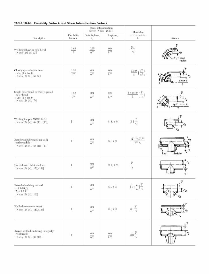
Welding elbow or pipe bend[Notes (2)], (4)-(7)]
Closely spaced miter bends < r2 (1 + tan θ) [Notes (2), (4), (5), (7)]
Single miter bend or widely spaced miter bend s ≥ r2 (1 + tan θ)[Notes (2), (4), (7)]
Welding tee per ASME B16.91 e io + d 3.1[Notes (2), (4), (6), (11), (13)]
Reinforced fabricated tee with pad or saddle 1 e io + d
[Notes (2), (4), (8), (12), (13)]
Unreinforced fabricated tee 1 e io + d[Notes (2), (4), (12), (13)]
Extruded welding tee withrx ≥ 0.05 Db
1 e ic + d 1 + Tc < 1.5 T[Notes (2), (4), (13)]
Welded-in contour insert1 e ic + d 3.1[Notes (2), (4), (11), (13)]
Branch welded-on fitting (integrally reinforced)[Notes (2), (4), (9), (12)]
1 3.3 Tr2
0.9h2/3
0.9h2/3
Tr2
0.9h2/3
Tr2
rxr2
0.9h2/3
Tr2
0.9h2/3
(T + 1⁄2 Tr)2.5
T 1.5 r2
0.9h2/3
Tr2
0.9h2/3
Tr2
1 + cot θ
20.9h2/3
0.9h2/3
1.52h5/6
sTr2
2
cot θ
2
0.9h2/3
0.9h2/3
1.52h5/6
TR1r2
20.9h2/3
0.75h2/3
1.65
h
TABLE 10-48 Flexibility Factor k and Stress Intensification Factor i
Stress intensificationfactor [Notes (2), (3)]
FlexibilityFlexibility Out-of-plane, In-plane, characteristic
Description factor k io ii h Sketch
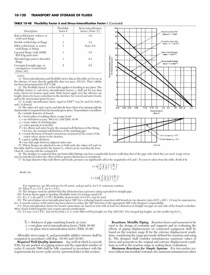
T⎯
b = thickness of pipe matching branch, in (mm)io = out-plane stress-intensification factor (Table 10-48)ii = in-plane stress-intensification factor (Table 10-48)
Allowable stress range SA and permissible additive stresses shall becomputed in accordance with Eqs. (10-93) and (10-94).
Required Weld Quality Assurance Any weld at which SE exceeds0.8SA for any portion of a piping system and the equivalent number ofcycles N exceeds 7000 shall be fully examined in accordance with therequirements for severe cyclic service (presented later in this section).
Reactions: Metallic Piping Reaction forces and moments to beused in the design of restraints and supports and in evaluating theeffects of piping displacements on connected equipment shall bebased on the reaction range R for the extreme displacement condi-tions, considering the range previously defined for reactions and usingEa. The designer shall consider instantaneous maximum values offorces and moments in the original and extreme displacement condi-tions as well as the reaction range in making these evaluations.
Maximum Reactions for Simple Systems For two-anchor sys-tems without intermediate restraints, the maximum instantaneous values
10-120 TRANSPORT AND STORAGE OF FLUIDS
TABLE 10-48 Flexibility Factor k and Stress-Intensification Factor i (Concluded)
Flexibility Stress intensificationDescription factor k factor i [Note (1)]
Butt-welded joint, reducer, or 1 1.0weld-neck flange
Double-welded slip-on flange 1 1.2Fillet welded joint, or socket 1 Note (14)weld flange or fitting
Lap joint flange (with ASME 1 1.6B16.9 lap joint stub)
Threaded pipe joint or threaded 1 2.3flange
Corrugated straight pipe, or 5 2.5corrugated or creased bend [Note (10)]
NOTES:(1) Stress intensification and flexibility factor data in this table are for use in
the absence of more directly applicable data (see para. 319.3.6). Their validityhas been demonstrated for D/T ≤ 100.
(2) The flexibility factor, k, in this table applies to bending in any plane. Theflexibility factors, k, and stress intensification factors, i, shall not be less thanunity; factors for torsion equal unity. Both factors apply over the effective arclength (shown by heavy centerlines in the sketches) for curved and miter bends,and to the intersection point for tees.
(3) A single intensification factor equal to 0.9/h2/3 may be used for both ii
and io if desired.(4) The values of k and i can be read directly from Chart A by entering with the
characteristic h computed from the formulas given above. Nomenclature is as follows:Db = outside diameter of branchR1 = bend radius of welding elbow or pipe bendrx = see definition in para. 304.3.4(c) and Table 10-48r2 = mean radius of matching pipes = miter spacing at centerline
T = for elbows and miter bends, the nominal wall thickness of the fitting,= for tees, the nominal wall thickness of the matching pipe
Tc = crotch thickness of branch connections measured at the center of the crotch where shown in the sketches
Tr = pad or saddle thicknessθ = one-half angle between adjacent miter axes
(5) Where flanges are attached to one or both ends, the values of k and i inthis table shall be corrected by the factors C1, which can be read directly from Chart B, entering with the computed h.
(6) The designer is cautioned that cast buttwelded fittings may have considerably heavier walls than that of the pipe with which they are used. Large errorsmay be introduced unless the effect of these greater thicknesses is considered.
(7) In large diameter thin-wall elbows and bends, pressure can significantly affect the magnitudes of k and i. To correct values from the table, divide k by
1 + 6 7/3 1/3
divide i by
1 + 3.25 5/2 2/3
For consistency, use kPa and mm for SI metric, and psi and in, for U.S. customary notation.(8) When T⎯r is > 1a T, use h = 4 T/r2.(9) The designer must be satisfied that this fabrication has a pressure rating equivalent to straight pipe.
(10) Factors shown apply to bending. Flexibility factor for torsion equals 0.9.(11) If rx ≥ 1/8 Db and Tc ≥ 1.5T a flexibility characteristic of 4.4 T/r2 may be used.(12) The out-of-plane stress intensification factor (SIF) for a reducing branch connection with branch-to-run diameter ratio of 0.5 < d/D < 1.0 may be nonconserva-
tive. A smooth concave weld contour has been shown to reduce the SIF. Selection of the appropriate SIF is the designer’s responsibility.(13) Stress intensification factors for branch connections are based on tests with at least two diameters of straight run pipe on each side of the branch centerline.
More closely loaded branches may require special consideration.(14) 2.1 max. or 2.1 T /Cx, but not less than 1.3. Cx is the fillet weld leg length (see Fig. 328.5.2C). For unequal leg lengths, use the smaller leg for Cx.
R1r2
r2T⎯
PE
R1r2
r2T⎯
PE
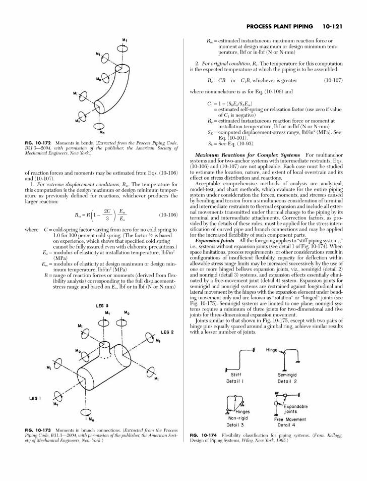
PROCESS PLANT PIPING 10-121
FIG. 10-172 Moments in bends. (Extracted from the Process Piping Code,B31.3—2004, with permission of the publisher, the American Society ofMechanical Engineers, New York.)
FIG. 10-173 Moments in branch connections. (Extracted from the ProcessPiping Code, B31.3—2004, with permission of the publisher, the American Soci-ety of Mechanical Engineers, New York.)
of reaction forces and moments may be estimated from Eqs. (10-106)and (10-107).
1. For extreme displacement conditions, Rm. The temperature forthis computation is the design maximum or design minimum temper-ature as previously defined for reactions, whichever produces thelarger reaction:
Rm = R 1 − (10-106)
where C = cold-spring factor varying from zero for no cold spring to1.0 for 100 percent cold spring. (The factor 2⁄3 is basedon experience, which shows that specified cold springcannot be fully assured even with elaborate precautions.)
Ea = modulus of elasticity at installation temperature, lbf/in2
(MPa)Em = modulus of elasticity at design maximum or design min-
imum temperature, lbf/in2 (MPa)R = range of reaction forces or moments (derived from flex-
ibility analysis) corresponding to the full displacement-stress range and based on Ea, lbf or in⋅lbf (N or N⋅mm)
EmEa
2C
3
Rm = estimated instantaneous maximum reaction force ormoment at design maximum or design minimum tem-perature, lbf or in⋅lbf (N or N⋅mm)
2. For original condition, Ra. The temperature for this computationis the expected temperature at which the piping is to be assembled.
Ra = CR or C1R, whichever is greater (10-107)
where nomenclature is as for Eq. (10-106) and
C1 = 1 − (ShEa/SEEm)= estimated self-spring or relaxation factor (use zero if value
of C1 is negative)Ra = estimated instantaneous reaction force or moment at
installation temperature, lbf or in⋅lbf (N or N⋅mm)SE = computed displacement-stress range, lbf/in2 (MPa). See
Eq. (10-101).Sh = See Eq. (10-93).
Maximum Reactions for Complex Systems For multianchorsystems and for two-anchor systems with intermediate restraints, Eqs.(10-106) and (10-107) are not applicable. Each case must be studiedto estimate the location, nature, and extent of local overstrain and itseffect on stress distribution and reactions.
Acceptable comprehensive methods of analysis are analytical,model-test, and chart methods, which evaluate for the entire pipingsystem under consideration the forces, moments, and stresses causedby bending and torsion from a simultaneous consideration of terminaland intermediate restraints to thermal expansion and include all exter-nal movements transmitted under thermal change to the piping by itsterminal and intermediate attachments. Correction factors, as pro-vided by the details of these rules, must be applied for the stress inten-sification of curved pipe and branch connections and may be appliedfor the increased flexibility of such component parts.
Expansion Joints All the foregoing applies to “stiff piping systems,”i.e., systems without expansion joints (see detail 1 of Fig. 10-174). Whenspace limitations, process requirements, or other considerations result inconfigurations of insufficient flexibility, capacity for deflection withinallowable stress range limits may be increased successively by the use ofone or more hinged bellows expansion joints, viz., semirigid (detail 2)and nonrigid (detail 3) systems, and expansion effects essentially elimi-nated by a free-movement joint (detail 4) system. Expansion joints forsemirigid and nonrigid systems are restrained against longitudinal andlateral movement by the hinges with the expansion element under bend-ing movement only and are known as “rotation” or “hinged” joints (seeFig. 10-175). Semirigid systems are limited to one plane; nonrigid sys-tems require a minimum of three joints for two-dimensional and fivejoints for three-dimensional expansion movement.
Joints similar to that shown in Fig. 10-175, except with two pairs ofhinge pins equally spaced around a gimbal ring, achieve similar resultswith a lesser number of joints.
FIG. 10-174 Flexibility classification for piping systems. (From Kellogg,Design of Piping Systems, Wiley, New York, 1965.)
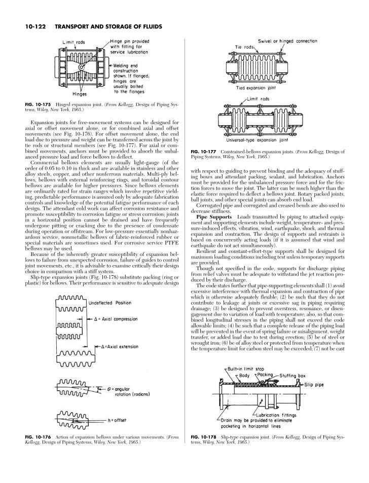
10-122 TRANSPORT AND STORAGE OF FLUIDS
Expansion joints for free-movement systems can be designed foraxial or offset movement alone, or for combined axial and offsetmovements (see Fig. 10-176). For offset movement alone, the endload due to pressure and weight can be transferred across the joint bytie rods or structural members (see Fig. 10-177). For axial or com-bined movements, anchors must be provided to absorb the unbal-anced pressure load and force bellows to deflect.
Commercial bellows elements are usually light-gauge (of theorder of 0.05 to 0.10 in thick and are available in stainless and otheralloy steels, copper, and other nonferrous materials. Multi-ply bel-lows, bellows with external reinforcing rings, and toroidal contourbellows are available for higher pressures. Since bellows elementsare ordinarily rated for strain ranges which involve repetitive yield-ing, predictable performance is assured only by adequate fabricationcontrols and knowledge of the potential fatigue performance of eachdesign. The attendant cold work can affect corrosion resistance andpromote susceptibility to corrosion fatigue or stress corrosion; jointsin a horizontal position cannot be drained and have frequentlyundergone pitting or cracking due to the presence of condensateduring operation or offstream. For low-pressure essentially nonhaz-ardous service, nonmetallic bellows of fabric-reinforced rubber orspecial materials are sometimes used. For corrosive service PTFEbellows may be used.
Because of the inherently greater susceptibility of expansion bel-lows to failure from unexpected corrosion, failure of guides to controljoint movements, etc., it is advisable to examine critically their designchoice in comparison with a stiff system.
Slip-type expansion joints (Fig. 10-178) substitute packing (ring orplastic) for bellows. Their performance is sensitive to adequate design
FIG. 10-175 Hinged expansion joint. (From Kellogg, Design of Piping Sys-tems, Wiley, New York, 1965.)
FIG. 10-176 Action of expansion bellows under various movements. (FromKellogg, Design of Piping Systems, Wiley, New York, 1965.)
FIG. 10-177 Constrained-bellows expansion joints. (From Kellogg, Design ofPiping Systems, Wiley, New York, 1965.)
FIG. 10-178 Slip-type expansion joint. (From Kellogg, Design of Piping Sys-tems, Wiley, New York, 1965.)
with respect to guiding to prevent binding and the adequacy of stuff-ing boxes and attendant packing, sealant, and lubrication. Anchorsmust be provided for the unbalanced pressure force and for the fric-tion forces to move the joint. The latter can be much higher than theelastic force required to deflect a bellows joint. Rotary packed joints,ball joints, and other special joints can absorb end load.
Corrugated pipe and corrugated and creased bends are also used todecrease stiffness.
Pipe Supports Loads transmitted by piping to attached equip-ment and supporting elements include weight, temperature- and pres-sure-induced effects, vibration, wind, earthquake, shock, and thermalexpansion and contraction. The design of supports and restraints isbased on concurrently acting loads (if it is assumed that wind andearthquake do not act simultaneously).
Resilient and constant-effort-type supports shall be designed formaximum loading conditions including test unless temporary supportsare provided.
Though not specified in the code, supports for discharge pipingfrom relief valves must be adequate to withstand the jet reaction pro-duced by their discharge.
The code states further that pipe-supporting elements shall (1) avoidexcessive interference with thermal expansion and contraction of pipewhich is otherwise adequately flexible; (2) be such that they do notcontribute to leakage at joints or excessive sag in piping requiringdrainage; (3) be designed to prevent overstress, resonance, or disen-gagement due to variation of load with temperature; also, so that com-bined longitudinal stresses in the piping shall not exceed the codeallowable limits; (4) be such that a complete release of the piping loadwill be prevented in the event of spring failure or misalignment, weighttransfer, or added load due to test during erection; (5) be of steel orwrought iron; (6) be of alloy steel or protected from temperature whenthe temperature limit for carbon steel may be exceeded; (7) not be cast
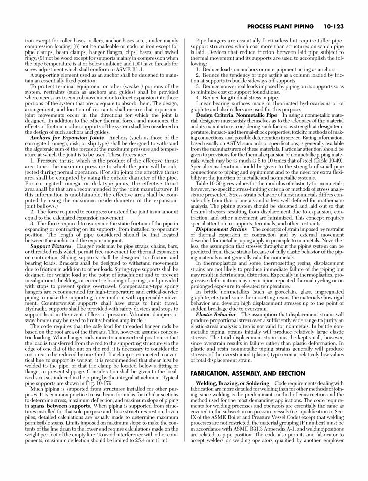
iron except for roller bases, rollers, anchor bases, etc., under mainlycompression loading; (8) not be malleable or nodular iron except forpipe clamps, beam clamps, hanger flanges, clips, bases, and swivelrings; (9) not be wood except for supports mainly in compression whenthe pipe temperature is at or below ambient; and (10) have threads forscrew adjustment which shall conform to ASME B1.1.
A supporting element used as an anchor shall be designed to main-tain an essentially fixed position.
To protect terminal equipment or other (weaker) portions of thesystem, restraints (such as anchors and guides) shall be providedwhere necessary to control movement or to direct expansion into thoseportions of the system that are adequate to absorb them. The design,arrangement, and location of restraints shall ensure that expansion-joint movements occur in the directions for which the joint isdesigned. In addition to the other thermal forces and moments, theeffects of friction in other supports of the system shall be considered inthe design of such anchors and guides.
Anchors for Expansion Joints Anchors (such as those of thecorrugated, omega, disk, or slip type) shall be designed to withstandthe algebraic sum of the forces at the maximum pressure and temper-ature at which the joint is to be used. These forces are:
1. Pressure thrust, which is the product of the effective thrustarea times the maximum pressure to which the joint will be sub-jected during normal operation. (For slip joints the effective thrustarea shall be computed by using the outside diameter of the pipe.For corrugated, omega, or disk-type joints, the effective thrustarea shall be that area recommended by the joint manufacturer. Ifthis information is unobtainable, the effective area shall be com-puted by using the maximum inside diameter of the expansion-joint bellows.)
2. The force required to compress or extend the joint in an amountequal to the calculated expansion movement.
3. The force required to overcome the static friction of the pipe inexpanding or contracting on its supports, from installed to operatingposition. The length of pipe considered should be that locatedbetween the anchor and the expansion joint.
Support Fixtures Hanger rods may be pipe straps, chains, bars,or threaded rods which permit free movement for thermal expansionor contraction. Sliding supports shall be designed for friction andbearing loads. Brackets shall be designed to withstand movementsdue to friction in addition to other loads. Spring-type supports shall bedesigned for weight load at the point of attachment and to preventmisalignment, buckling, or eccentric loading of springs, and providedwith stops to prevent spring overtravel. Compensating-type springhangers are recommended for high-temperature and critical-servicepiping to make the supporting force uniform with appreciable move-ment. Counterweight supports shall have stops to limit travel.Hydraulic supports shall be provided with safety devices and stops tosupport load in the event of loss of pressure. Vibration dampers orsway braces may be used to limit vibration amplitude.
The code requires that the safe load for threaded hanger rods bebased on the root area of the threads. This, however, assumes concen-tric loading. When hanger rods move to a nonvertical position so thatthe load is transferred from the rod to the supporting structure via theedge of one flat of the nut on the rod, it is necessary to consider theroot area to be reduced by one-third. If a clamp is connected to a ver-tical line to support its weight, it is recommended that shear lugs bewelded to the pipe, or that the clamp be located below a fitting orflange, to prevent slippage. Consideration shall be given to the local-ized stresses induced in the piping by the integral attachment. Typicalpipe supports are shown in Fig. 10-179.
Much piping is supported from structures installed for other pur-poses. It is common practice to use beam formulas for tubular sectionsto determine stress, maximum deflection, and maximum slope of pipingin spans between supports. When piping is supported from struc-tures installed for that sole purpose and those structures rest on drivenpiles, detailed calculations are usually made to determine maximumpermissible spans. Limits imposed on maximum slope to make the con-tents of the line drain to the lower end require calculations made on theweight per foot of the empty line. To avoid interference with other com-ponents, maximum deflection should be limited to 25.4 mm (1 in).
PROCESS PLANT PIPING 10-123
Pipe hangers are essentially frictionless but require taller pipe-support structures which cost more than structures on which pipeis laid. Devices that reduce friction between laid pipe subject tothermal movement and its supports are used to accomplish the fol-lowing:
1. Reduce loads on anchors or on equipment acting as anchors.2. Reduce the tendency of pipe acting as a column loaded by fric-
tion at supports to buckle sideways off supports.3. Reduce nonvertical loads imposed by piping on its supports so as
to minimize cost of support foundations.4. Reduce longitudinal stress in pipe.Linear bearing surfaces made of fluorinated hydrocarbons or of
graphite and also rollers are used for this purpose.Design Criteria: Nonmetallic Pipe In using a nonmetallic mate-
rial, designers must satisfy themselves as to the adequacy of the materialand its manufacture, considering such factors as strength at design tem-perature, impact- and thermal-shock properties, toxicity, methods of mak-ing connections, and possible deterioration in service. Rating information,based usually on ASTM standards or specifications, is generally availablefrom the manufacturers of these materials. Particular attention should begiven to provisions for the thermal expansion of nonmetallic piping mate-rials, which may be as much as 5 to 10 times that of steel (Table 10-49).Special consideration should be given to the strength of small pipeconnections to piping and equipment and to the need for extra flexi-bility at the junction of metallic and nonmetallic systems.
Table 10-50 gives values for the modulus of elasticity for nonmetals;however, no specific stress-limiting criteria or methods of stress analy-sis are presented. Stress-strain behavior of most nonmetals differs con-siderably from that of metals and is less well-defined for mathematicanalysis. The piping system should be designed and laid out so thatflexural stresses resulting from displacement due to expansion, con-traction, and other movement are minimized. This concept requiresspecial attention to supports, terminals, and other restraints.
Displacement Strains The concepts of strain imposed by restraintof thermal expansion or contraction and by external movementdescribed for metallic piping apply in principle to nonmetals. Neverthe-less, the assumption that stresses throughout the piping system can bepredicted from these strains because of fully elastic behavior of the pip-ing materials is not generally valid for nonmetals.
In thermoplastics and some thermosetting resins, displacementstrains are not likely to produce immediate failure of the piping butmay result in detrimental distortion. Especially in thermoplastics, pro-gressive deformation may occur upon repeated thermal cycling or onprolonged exposure to elevated temperature.
In brittle nonmetallics (such as porcelain, glass, impregnatedgraphite, etc.) and some thermosetting resins, the materials show rigidbehavior and develop high displacement stresses up to the point ofsudden breakage due to overstrain.
Elastic Behavior The assumption that displacement strains willproduce proportional stress over a sufficiently wide range to justify anelastic-stress analysis often is not valid for nonmetals. In brittle non-metallic piping, strains initially will produce relatively large elasticstresses. The total displacement strain must be kept small, however,since overstrain results in failure rather than plastic deformation. Inplastic and resin nonmetallic piping strains generally will producestresses of the overstrained (plastic) type even at relatively low valuesof total displacement strain.
FABRICATION, ASSEMBLY, AND ERECTION
Welding, Brazing, or Soldering Code requirements dealing withfabrication are more detailed for welding than for other methods of join-ing, since welding is the predominant method of construction and themethod used for the most demanding applications. The code require-ments for welding processes and operators are essentially the same ascovered in the subsection on pressure vessels (i.e., qualification to Sec.IX of the ASME Boiler and Pressure Vessel Code) except that weldingprocesses are not restricted, the material grouping (P number) must bein accordance with ASME B31.3 Appendix A-1, and welding positionsare related to pipe position. The code also permits one fabricator toaccept welders or welding operators qualified by another employer
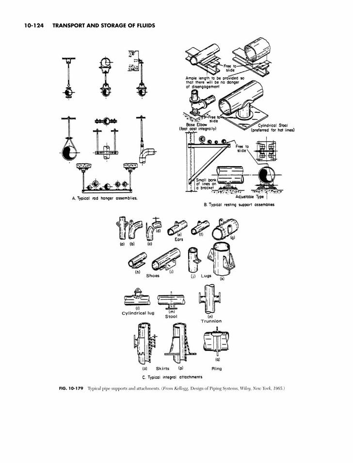
10-124 TRANSPORT AND STORAGE OF FLUIDS
FIG. 10-179 Typical pipe supports and attachments. (From Kellogg, Design of Piping Systems, Wiley, New York, 1965.)
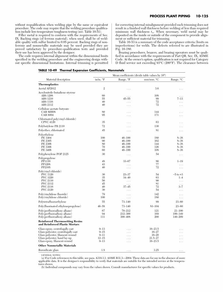
PROCESS PLANT PIPING 10-125
without requalification when welding pipe by the same or equivalentprocedure. The code may require that the welding procedure qualifica-tion include low-temperature toughness testing (see. Table 10-51).
Filler metal is required to conform with the requirements of Sec.IX. Backing rings (of ferrous material), when used, shall be of weld-able quality with sulfur limited to 0.05 percent. Backing rings of non-ferrous and nonmetallic materials may be used provided they areproved satisfactory by procedure-qualification tests and providedtheir use has been approved by the designer.
The code requires internal alignment within the dimensional limitsspecified in the welding procedure and the engineering design with-out specific dimensional limitations. Internal trimming is permitted
for correcting internal misalignment provided such trimming does notresult in a finished wall thickness before welding of less than requiredminimum wall thickness tm. When necessary, weld metal may bedeposited on the inside or outside of the component to provide align-ment or sufficient material for trimming.
Table 10-53 is a summary of the code acceptance criteria (limits onimperfections) for welds. The defects referred to are illustrated inFig. 10-180.
Brazing procedures, brazers, and brazing operators must be quali-fied in accordance with the requirements of Part QB, Sec. IX, ASMECode. At the owner’s option, qualification is not required for CategoryD fluid service not exceeding 93°C (200°F). The clearance between
TABLE 10-49 Thermal Expansion Coefficients, Nonmetals
Mean coefficients (divide table values by 106)Material description in/in, °F Range, °F mm/mm, °C Range, °C
ThermoplasticsAcetal AP2012 2 . . . 3.6 . . .Acrylonitrile-butadiene-styrene
ABS 1208 60 . . . 108 . . .ABS 1210 55 45–55 99 7–13ABS 1316 40 . . . 72 . . .ABS 2112 40 . . . 72 . . .
Cellulose acetate butyrateCAB MH08 80 . . . 144 . . .CAB S004 95 . . . 171 . . .
Chlorinated poly(vinyl chloride)CPVC 4120 35 . . . 63 . . .
Polybutylene PB 2110 72 . . . 130 . . .Polyether, chlorinated 45 . . . 81 . . .
PolyethylenePE 1404 100 46–100 180 8–38PE 2305 90 46–100 162 8–38PE 2306 80 46–100 144 8–38PE 3306 70 46–100 126 8–38PE 3406 60 46–100 108 8–38
Polyphenylene POP 2125 30 . . . 54 . . .Polypropylene
PP1110 48 33–67 86 1–19PP1208 43 . . . 77 . . .PP2105 40 . . . 72 . . .
Poly(vinyl chloride)PVC 1120 30 23–37 54 −5 to +3PVC 1220 35 34–40 63 1–4PVC 2110 50 . . . 90 . . .PVC 2112 45 . . . 81 . . .PVC 2116 40 37–45 72 3–7PVC 2120 30 . . . 54 . . .
Poly(vinylidene fluoride) 79 . . . 142 . . .Poly(vinylidene chloride) 100 . . . 180 . . .
Polytetrafluoroethylene 55 73–140 99 23–60
Poly(fluorinated ethylenepropylene) 46–58 73–140 83–104 23–60
Poly(perfluoroalkoxy alkane) 67 70–212 121 21–100Poly(perfluoroalkoxy alkane) 94 212–300 169 100–149Poly(perfluoroalkoxy alkane) 111 300–408 200 149–209
Reinforced Thermosetting Resins and Reinforced Plastic Mortars
Glass-epoxy, centrifugally cast 9–13 . . . 16–23.5 . . .Glass-polyester, centrifugally cast 9–15 . . . 16–27 . . .Glass-polyester, filament-wound 9–11 . . . 16–20 . . .Glass-polyester, hand lay-up 12–15 . . . 21.5–27 . . .Glass-epoxy, filament-wound 9–13 . . . 16–23.5 . . .
Other Nonmetallic Materials
Borosilicate glass 1.8 . . . 3.25 . . .
GENERAL NOTES:(a) For Code references to this table, see para. A319.3.1, ASME B31.3—2004. These data are for use in the absence of more
applicable data. It is the designer’s responsibility to verify that materials are suitable for the intended service at the tempera-tures shown.
(b) Individual compounds may vary from the values shown. Consult manufacturer for specific values for products.
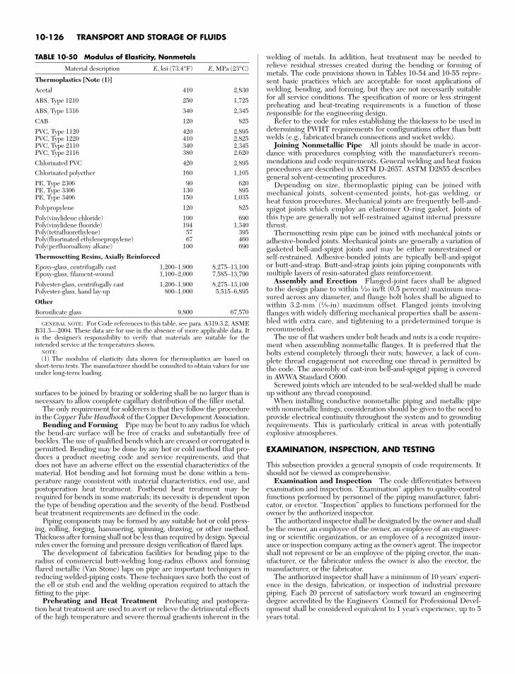
surfaces to be joined by brazing or soldering shall be no larger than isnecessary to allow complete capillary distribution of the filler metal.
The only requirement for solderers is that they follow the procedurein the Copper Tube Handbook of the Copper Development Association.
Bending and Forming Pipe may be bent to any radius for whichthe bend-arc surface will be free of cracks and substantially free ofbuckles. The use of qualified bends which are creased or corrugated ispermitted. Bending may be done by any hot or cold method that pro-duces a product meeting code and service requirements, and thatdoes not have an adverse effect on the essential characteristics of thematerial. Hot bending and hot forming must be done within a tem-perature range consistent with material characteristics, end use, andpostoperation heat treatment. Postbend heat treatment may berequired for bends in some materials; its necessity is dependent uponthe type of bending operation and the severity of the bend. Postbendheat treatment requirements are defined in the code.
Piping components may be formed by any suitable hot or cold press-ing, rolling, forging, hammering, spinning, drawing, or other method.Thickness after forming shall not be less than required by design. Specialrules cover the forming and pressure design verification of flared laps.
The development of fabrication facilities for bending pipe to theradius of commercial butt-welding long-radius elbows and formingflared metallic (Van Stone) laps on pipe are important techniques inreducing welded-piping costs. These techniques save both the cost ofthe ell or stub end and the welding operation required to attach thefitting to the pipe.
Preheating and Heat Treatment Preheating and postopera-tion heat treatment are used to avert or relieve the detrimental effectsof the high temperature and severe thermal gradients inherent in the
welding of metals. In addition, heat treatment may be needed torelieve residual stresses created during the bending or forming ofmetals. The code provisions shown in Tables 10-54 and 10-55 repre-sent basic practices which are acceptable for most applications ofwelding, bending, and forming, but they are not necessarily suitablefor all service conditions. The specification of more or less stringentpreheating and heat-treating requirements is a function of thoseresponsible for the engineering design.
Refer to the code for rules establishing the thickness to be used indetermining PWHT requirements for configurations other than buttwelds (e.g., fabricated branch connections and socket welds).
Joining Nonmetallic Pipe All joints should be made in accor-dance with procedures complying with the manufacturer’s recom-mendations and code requirements. General welding and heat fusionprocedures are described in ASTM D-2657. ASTM D2855 describesgeneral solvent-cementing procedures.
Depending on size, thermoplastic piping can be joined withmechanical joints, solvent-cemented joints, hot-gas welding, orheat fusion procedures. Mechanical joints are frequently bell-and-spigot joints which employ an elastomer O-ring gasket. Joints ofthis type are generally not self-restrained against internal pressurethrust.
Thermosetting resin pipe can be joined with mechanical joints oradhesive-bonded joints. Mechanical joints are generally a variation ofgasketed bell-and-spigot joints and may be either nonrestrained orself-restrained. Adhesive-bonded joints are typically bell-and-spigotor butt-and-strap. Butt-and-strap joints join piping components withmultiple layers of resin-saturated glass reinforcement.
Assembly and Erection Flanged-joint faces shall be alignedto the design plane to within 1⁄10 in/ft (0.5 percent) maximum mea-sured across any diameter, and flange bolt holes shall be aligned towithin 3.2-mm (1⁄8-in) maximum offset. Flanged joints involvingflanges with widely differing mechanical properties shall be assem-bled with extra care, and tightening to a predetermined torque isrecommended.
The use of flat washers under bolt heads and nuts is a code require-ment when assembling nonmetallic flanges. It is preferred that thebolts extend completely through their nuts; however, a lack of com-plete thread engagement not exceeding one thread is permitted bythe code. The assembly of cast-iron bell-and-spigot piping is coveredin AWWA Standard C600.
Screwed joints which are intended to be seal-welded shall be madeup without any thread compound.
When installing conductive nonmetallic piping and metallic pipewith nonmetallic linings, consideration should be given to the need toprovide electrical continuity throughout the system and to groundingrequirements. This is particularly critical in areas with potentiallyexplosive atmospheres.
EXAMINATION, INSPECTION, AND TESTING
This subsection provides a general synopsis of code requirements. Itshould not be viewed as comprehensive.
Examination and Inspection The code differentiates betweenexamination and inspection. “Examination” applies to quality-controlfunctions performed by personnel of the piping manufacturer, fabri-cator, or erector. “Inspection” applies to functions performed for theowner by the authorized inspector.
The authorized inspector shall be designated by the owner and shallbe the owner, an employee of the owner, an employee of an engineer-ing or scientific organization, or an employee of a recognized insur-ance or inspection company acting as the owner’s agent. The inspectorshall not represent or be an employee of the piping erector, the man-ufacturer, or the fabricator unless the owner is also the erector, themanufacturer, or the fabricator.
The authorized inspector shall have a minimum of 10 years’ experi-ence in the design, fabrication, or inspection of industrial pressurepiping. Each 20 percent of satisfactory work toward an engineeringdegree accredited by the Engineers’ Council for Professional Devel-opment shall be considered equivalent to 1 year’s experience, up to 5years total.
10-126 TRANSPORT AND STORAGE OF FLUIDS
TABLE 10-50 Modulus of Elasticity, Nonmetals
Material description E, ksi (73.4°F) E, MPa (23°C)
Thermoplastics [Note (1)]
Acetal 410 2,830
ABS, Type 1210 250 1,725
ABS, Type 1316 340 2,345
CAB 120 825
PVC, Type 1120 420 2,895PVC, Type 1220 410 2,825PVC, Type 2110 340 2,345PVC, Type 2116 380 2,620
Chlorinated PVC 420 2,895Chlorinated polyether 160 1,105
PE, Type 2306 90 620PE, Type 3306 130 895PE, Type 3406 150 1,035
Polypropylene 120 825
Poly(vinylidene chloride) 100 690Poly(vinylidene fluoride) 194 1,340Poly(tetrafluorethylene) 57 395Poly(fluorinated ethylenepropylene) 67 460Poly(perfluoroalkoxy alkane) 100 690
Thermosetting Resins, Axially Reinforced
Epoxy-glass, centrifugally cast 1,200–1,900 8,275–13,100Epoxy-glass, filament-wound 1,100–2,000 7,585–13,790
Polyester-glass, centrifugally cast 1,200–1,900 8,275–13,100Polyester-glass, hand lay-up 800–1,000 5,515–6,895
Other
Borosilicate glass 9,800 67,570
GENERAL NOTE: For Code references to this table, see para. A319.3.2, ASMEB31.3—2004. These data are for use in the absence of more applicable data. Itis the designer’s responsibility to verify that materials are suitable for theintended service at the temperatures shown.
NOTE:(1) The modulus of elasticity data shown for thermoplastics are based on
short-term tests. The manufacturer should be consulted to obtain values for useunder long-term loading.
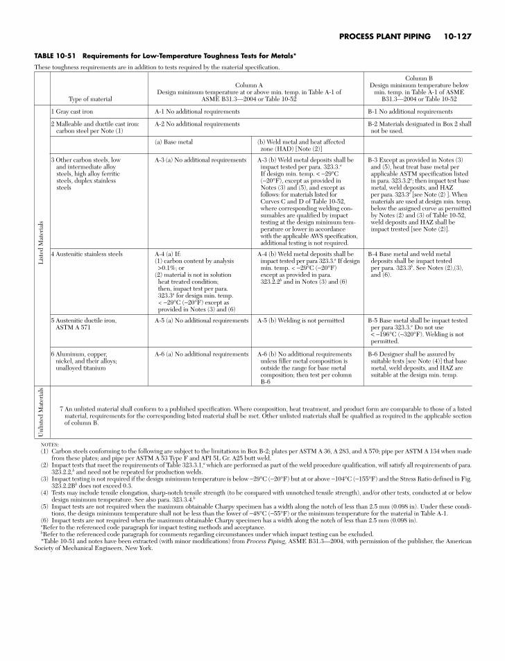
PROCESS PLANT PIPING 10-127
TABLE 10-51 Requirements for Low-Temperature Toughness Tests for Metals*
These toughness requirements are in addition to tests required by the material specification.
Column BColumn A Design minimum temperature below
Design minimum temperature at or above min. temp. in Table A-1 of min. temp. in Table A-1 of ASMEType of material ASME B31.3—2004 or Table 10-52 B31.3—2004 or Table 10-52
1 Gray cast iron A-1 No additional requirements B-1 No additional requirements
2 Malleable and ductile cast iron: A-2 No additional requirements B-2 Materials designated in Box 2 shall carbon steel per Note (1) not be used.
(a) Base metal (b) Weld metal and heat affectedzone (HAD) [Note (2)]
3 Other carbon steels, low A-3 (a) No additional requirements A-3 (b) Weld metal deposits shall be B-3 Except as provided in Notes (3)and intermediate alloy impact tested per para. 323.3.a and (5), heat treat base metal per steels, high alloy ferritic If design min. temp. < −29°C applicable ASTM specification listedsteels, duplex stainless (−20°F), except as provided in in para. 323.3.2a; then impact test basesteels Notes (3) and (5), and except as metal, weld deposits, and HAZ
follows: for materials listed for per para. 323.3a [see Note (2) ]. WhenCurves C and D of Table 10-52, materials are used at design min. temp.where corresponding welding con- below the assigned curve as permitted sumables are qualified by impact by Notes (2) and (3) of Table 10-52,testing at the design minimum tem- weld deposits and HAZ shall be perature or lower in accordance impact trested [see Note (2)].with the applicable AWS specification,additional testing is not required.
4 Austenitic stainless steels A-4 (a) If: A-4 (b) Weld metal deposits shall be B-4 Base metal and weld metal (1) carbon content by analysis impact tested per para 323.3.a If design deposits shall be impact tested >0.1%; or min. temp. < −29°C (−20°F) per para. 323.3b. See Notes (2),(3),
(2) material is not in solution except as provided in para. and (6).heat treated condition; 323.2.2b and in Notes (3) and (6)then, impact test per para.323.3a for design min. temp.< −29°C (−20°F) except asprovided in Notes (3) and (6)
5 Austenitic ductile iron, A-5 (a) No additional requirements A-5 (b) Welding is not permitted B-5 Base metal shall be impact testedASTM A 571 per para 323.3.a Do not use
< −196°C (−320°F). Welding is not permitted.
6 Aluminum, copper, A-6 (a) No additional requirements A-6 (b) No additional requirements B-6 Designer shall be assured by nickel, and their alloys; unless filler metal composition is suitable tests [see Note (4)] that baseunalloyed titanium outside the range for base metal metal, weld deposits, and HAZ are
composition; then test per column suitable at the design min. temp.B-6
7 An unlisted material shall conform to a published specification. Where composition, heat treatment, and product form are comparable to those of a listedmaterial, requirements for the corresponding listed material shall be met. Other unlisted materials shall be qualified as required in the applicable sectionof column B.
Unl
iste
d M
ater
ials
Lis
ted
Mat
eria
ls
NOTES:(1) Carbon steels conforming to the following are subject to the limitations in Box B-2; plates per ASTM A 36, A 283, and A 570; pipe per ASTM A 134 when made
from these plates; and pipe per ASTM A 53 Type F and API 5L Gr. A25 butt weld.(2) Impact tests that meet the requirements of Table 323.3.1,a which are performed as part of the weld procedure qualification, will satisfy all requirements of para.
323.2.2,b and need not be repeated for production welds.(3) Impact testing is not required if the design minimum temperature is below −29°C (−20°F) but at or above −104°C (−155°F) and the Stress Ratio defined in Fig.
323.2.2Bb does not exceed 0.3.(4) Tests may include tensile elongation, sharp-notch tensile strength (to be compared with unnotched tensile strength), and/or other tests, conducted at or below
design minimum temperature. See also para. 323.3.4.b(5) Impact tests are not required when the maximum obtainable Charpy specimen has a width along the notch of less than 2.5 mm (0.098 in). Under these condi-
tions, the design minimum temperature shall not be less than the lower of −48°C (−55°F) or the minimum temperature for the material in Table A-1.(6) Impact tests are not required when the maximum obtainable Charpy specimen has a width along the notch of less than 2.5 mm (0.098 in).aRefer to the referenced code paragraph for impact testing methods and acceptance.bRefer to the referenced code paragraph for comments regarding circumstances under which impact testing can be excluded.*Table 10-51 and notes have been extracted (with minor modifications) from Process Piping, ASME B31.3—2004, with permission of the publisher, the American
Society of Mechanical Engineers, New York.
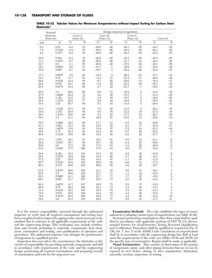
10-128 TRANSPORT AND STORAGE OF FLUIDS
TABLE 10-52 Tabular Values for Minimum Temperatures without Impact Testing for Carbon SteelMaterials*
Nominal Design minimum temperaturethickness Curve A Curve B Curve C[Note (6)] [Note (2)] [Note (3)] [Note (3)] Curve D
mm in ºC ºF ºC ºF ºC ºF ºC ºF
6.4 0.25 –9.4 15 –28.9 –20 –48.3 –55 –48.3 –557.9 0.3125 –9.4 15 –28.9 –20 –48.3 –55 –48.3 –559.5 0.375 –9.4 15 –28.9 –20 –48.3 –55 –48.3 –55
10.0 0.394 –9.4 15 –28.9 –20 –48.3 –55 –48.3 –5511.1 0.4375 –6.7 20 –28.9 –20 –41.7 –43 –48.3 –5512.7 0.5 –1.1 30 –28.9 –20 –37.8 –36 –48.3 –5514.3 0.5625 2.8 37 –21.7 –7 –35.0 –31 –45.6 –5015.9 0.625 6.1 43 –16.7 2 –32.2 –26 –43.9 –47
17.5 0.6875 8.9 48 –12.8 9 –29.4 –21 –41.7 –4319.1 0.75 11.7 53 –9.4 15 –27.2 –17 –40.0 –4020.6 0.8125 14.4 58 –6.7 20 –25.0 –13 –38.3 –3722.2 0.875 16.7 62 –3.9 25 –23.3 –10 –36.7 –3423.8 0.9375 18.3 65 –1.7 29 –21.7 –7 –35.6 –32
25.4 1.0 20.0 68 0.6 33 –19.4 –3 –34.4 –3027.0 1.0625 22.2 72 2.2 36 –18.3 –1 –33.3 –2828.6 1.125 23.9 75 3.9 39 –16.7 2 –32.2 –2630.2 1.1875 25.0 77 5.6 42 –15.6 4 –30.6 –2331.8 1.25 26.7 80 6.7 44 –14.4 6 –29.4 –21
33.3 1.3125 27.8 82 7.8 46 –13.3 8 –28.3 –1934.9 1.375 28.9 84 8.9 48 –12.2 10 –27.8 –1836.5 1.4375 30.0 86 9.4 49 –11.1 12 –26.7 –1638.1 1.5 31.1 88 10.6 51 –10.0 14 –25.6 –14
39.7 1.5625 32.2 90 11.7 53 –8.9 16 –25.0 –1341.3 1.625 33.3 92 12.8 55 –8.3 17 –23.9 –1142.9 1.6875 33.9 93 13.9 57 –7.2 19 –23.3 –1044.5 1.75 34.4 94 14.4 58 –6.7 20 –22.2 –846.0 1.8125 35.6 96 15.0 59 –5.6 22 –21.7 –7
47.6 1.875 36.1 97 16.1 61 –5.0 23 –21.1 –649.2 1.9375 36.7 98 16.7 62 –4.4 24 –20.6 –550.8 2.0 37.2 99 17.2 63 –3.3 26 –20.0 –451.6 2.0325 37.8 100 17.8 64 –2.8 27 –19.4 –3
54.0 2.125 38.3 101 18.3 65 –2.2 28 –18.9 –255.6 2.1875 38.9 102 18.9 66 –1.7 29 –18.3 –157.2 2.25 38.9 102 19.4 67 –1.1 30 –17.8 058.7 2.3125 39.4 103 20.0 68 –0.6 31 –17.2 160.3 2.375 40.0 104 20.6 69 0.0 32 –16.7 2
61.9 2.4375 40.6 105 21.1 70 0.6 33 –16.1 363.5 2.5 40.6 105 21.7 71 1.1 34 –15.6 465.1 2.5625 41.1 106 21.7 71 1.7 35 –15.0 566.7 2.625 41.7 107 22.8 73 2.2 36 –14.4 6
68.3 2.6875 41.7 107 22.8 73 2.8 37 –13.9 769.9 2.75 42.2 108 23.3 74 3.3 38 –13.3 871.4 2.8125 42.2 108 23.9 75 3.9 39 –13.3 873.0 2.875 42.8 109 24.4 76 4.4 40 –12.8 974.6 2.9375 42.8 109 25.0 77 4.4 40 –12.2 1076.2 3.0 43.3 110 25.0 77 5.0 41 –11.7 11
It is the owner’s responsibility, exercised through the authorizedinspector, to verify that all required examinations and testing havebeen completed and to inspect the piping to the extent necessary to besatisfied that it conforms to all applicable requirements of the codeand the engineering design. This verification may include certifica-tions and records pertaining to materials, components, heat treat-ment, examination and testing, and qualifications of operators andprocedures. The authorized inspector may delegate the performanceof inspection to a qualified person.
Inspection does not relieve the manufacturer, the fabricator, or theerector of responsibility for providing materials, components, and skillin accordance with requirements of the code and the engineeringdesign, performing all required examinations, and preparing recordsof examinations and tests for the inspector’s use.
Examination Methods The code establishes the types of exami-nations for evaluating various types of imperfections (see Table 10-56).
Personnel performing examinations other than visual shall be qual-ified in accordance with applicable portions of SNT TC-1A, Recom-mended Practice for Nondestructive Testing Personnel Qualificationand Certification. Procedures shall be qualified as required in Par. T-150, Art. 1, Sec. V of the ASME Code. Limitations on imperfectionsshall be in accordance with the engineering design but shall at leastmeet the requirements of the code (see Tables 10-54 and 10-55) forthe specific type of examination. Repairs shall be made as applicable.
Visual Examination This consists of observation of the portionof components, joints, and other piping elements that are or can beexposed to view before, during, or after manufacture, fabrication,assembly, erection, inspection, or testing.
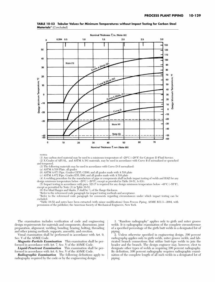
PROCESS PLANT PIPING 10-129
TABLE 10-52 Tabular Values for Minimum Temperatures without Impact Testing for Carbon Steel Materials* (Concluded )
NOTES:(1) Any carbon steel material may be used to a minimum temperature of −29°C (−20°F) for Category D Fluid Service.(2) X Grades of API SL, and ASTM A 381 materials, may be used in accordance with Curve B if normalized or quenched
and tempered.(3) The following materials may be used in accordance with Curve D if normalized:(a) ASTM A 516 Plate, all grades(b) ASTM A 671 Pipe, Grades CE55, CE60, and all grades made with A 516 plate(c) ASTM A 672 Pipe, Grades E55, E60, and all grades made with A 516 plate(4) A welding procedure for the manufacture of pipe or components shall include impact testing of welds and HAZ for any
design minimum temperature below −29°C (−20°F), except as provided in Table 10-51, A-3(b).(5) Impact testing in accordance with para. 323.3b is required for any design minimum temperature below −48°C (−55°F),
except as permitted by Note (3) in Table 10-51.(6) For blind flanges and blanks, T
⎯shall be 1/4 of the flange thickness.
aRefer to the referenced code paragraph for impact testing methods and acceptance.bRefer to the referenced code paragraph for comments regarding circumstances under which impact testing can be
excluded.*Table 10-52 and notes have been extracted (with minor modifications) from Process Piping, ASME B31.3—2004, with
permission of the publisher, the American Society of Mechanical Engineers, New York.
The examination includes verification of code and engineeringdesign requirements for materials and components, dimensions, jointpreparation, alignment, welding, bonding, brazing, bolting, threadingand other joining methods, supports, assembly, and erection.
Visual examination shall be performed in accordance with Art. 9,Sec. V of the ASME Code.
Magnetic-Particle Examination This examination shall be per-formed in accordance with Art. 7, Sec. V of the ASME Code.
Liquid-Penetrant Examination This examination shall be per-formed in accordance with Art. 6, Sec. V of the ASME Code.
Radiographic Examination The following definitions apply toradiography required by the code or by the engineering design:
1. “Random radiography” applies only to girth and miter groovewelds. It is radiographic examination of the complete circumferenceof a specified percentage of the girth butt welds in a designated lot ofpiping.
2. Unless otherwise specified in engineering design, 100 percentradiography applies only to girth welds, miter groove welds, and fab-ricated branch connections that utilize butt-type welds to join theheader and the branch. The design engineer may, however, elect todesignate other types of welds as requiring 100 percent radiography.By definition, 100 percent radiography requires radiographic exami-nation of the complete length of all such welds in a designated lot ofpiping.
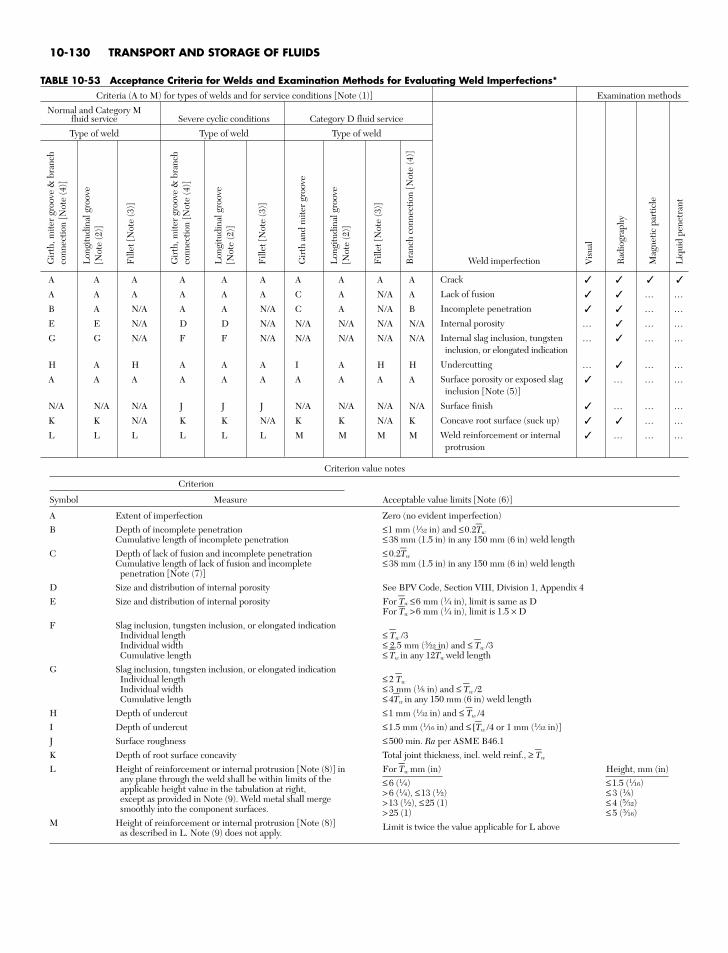
10-130 TRANSPORT AND STORAGE OF FLUIDS
Criterion value notes
Criterion
Symbol Measure Acceptable value limits [Note (6)]
A Extent of imperfection Zero (no evident imperfection)B Depth of incomplete penetration ≤1 mm (1⁄32 in) and ≤0.2T
⎯w
Cumulative length of incomplete penetration ≤ 38 mm (1.5 in) in any 150 mm (6 in) weld lengthC Depth of lack of fusion and incomplete penetration ≤ 0.2T
⎯w
Cumulative length of lack of fusion and incomplete ≤ 38 mm (1.5 in) in any 150 mm (6 in) weld lengthpenetration [Note (7)]
D Size and distribution of internal porosity See BPV Code, Section VIII, Division 1, Appendix 4E Size and distribution of internal porosity For T
⎯w ≤6 mm (1⁄4 in), limit is same as D
For T⎯w >6 mm (1⁄4 in), limit is 1.5 × DF Slag inclusion, tungsten inclusion, or elongated indication
Individual length ≤ T⎯
w /3Individual width ≤ 2.5 mm (3⁄22 in) and ≤ T
⎯w /3
Cumulative length ≤ T⎯
w in any 12T⎯
w weld lengthG Slag inclusion, tungsten inclusion, or elongated indication
Individual length ≤ 2 T⎯
w
Individual width ≤ 3 mm (1⁄8 in) and ≤ T⎯
w /2Cumulative length ≤ 4T
⎯w in any 150 mm (6 in) weld length
H Depth of undercut ≤1 mm (1⁄32 in) and ≤ T⎯
w /4I Depth of undercut ≤1.5 mm (1⁄16 in) and ≤ [T
⎯w /4 or 1 mm (1⁄32 in)]
J Surface roughness ≤ 500 min. Ra per ASME B46.1K Depth of root surface concavity Total joint thickness, incl. weld reinf., ≥ T
⎯w
L Height of reinforcement or internal protrusion [Note (8)] in For T⎯
w mm (in) Height, mm (in)any plane through the weld shall be within limits of the ≤ 6 (1⁄4) ≤1.5 (1⁄16)applicable height value in the tabulation at right, > 6 (1⁄4), ≤13 (1⁄2) ≤ 3 (1⁄8)except as provided in Note (9). Weld metal shall merge >13 (1⁄2), ≤25 (1) ≤ 4 (5⁄32)smoothly into the component surfaces. > 25 (1) ≤ 5 (3⁄16)
M Height of reinforcement or internal protrusion [Note (8)] Limit is twice the value applicable for L aboveas described in L. Note (9) does not apply.
TABLE 10-53 Acceptance Criteria for Welds and Examination Methods for Evaluating Weld Imperfections*Criteria (A to M) for types of welds and for service conditions [Note (1)] Examination methods
Normal and Category Mfluid service Severe cyclic conditions Category D fluid service
Type of weld Type of weld Type of weld
A A A A A A A A A A
A A A A A A C A N/A A … …B A N/A A A N/A C A N/A B … …E E N/A D D N/A N/A N/A N/A N/A … … …G G N/A F F N/A N/A N/A N/A N/A … … …
H A H A A A I A H H … … …A A A A A A A A A A … … …
N/A N/A N/A J J J N/A N/A N/A N/A … … …K K N/A K K N/A K K N/A K … …L L L L L L M M M M … … …
Gir
th, m
iter
groo
ve &
bra
nch
conn
ectio
n [N
ote
(4)]
Lon
gitu
dina
l gro
ove
[Not
e (2
)]
Fill
et [N
ote
(3)]
Gir
th, m
iter
groo
ve &
bra
nch
conn
ectio
n [N
ote
(4)]
Lon
gitu
dina
l gro
ove
[Not
e (2
)]
Fill
et [N
ote
(3)]
Gir
th a
nd m
iter
groo
ve
Lon
gitu
dina
l gro
ove
[Not
e (2
)]
Fill
et [N
ote
(3)]
Bra
nch
conn
ectio
n [N
ote
(4)]
Vis
ual
Rad
iogr
aphy
Mag
netic
par
ticle
Liq
uid
pene
tran
t
Weld imperfection
Crack
Lack of fusion
Incomplete penetration
Internal porosity
Internal slag inclusion, tungsteninclusion, or elongated indication
Undercutting
Surface porosity or exposed slaginclusion [Note (5)]
Surface finish
Concave root surface (suck up)
Weld reinforcement or internalprotrusion
PROCESS PLANT PIPING 10-131
TABLE 10-53 Acceptance Criteria for Welds and Examination Methods for Evaluating Weld Imperfections* (Concluded )
GENERAL NOTES:(a) Weld imperfections are evaluated by one or more of the types of examination methods. The types and extent of examination shall comply with code requirements
and those specified by engineering design.(b) “N/A” indicates the code does not establish acceptance criteria or does not require evaluation of this kind of imperfection for this type of weld.(c) Check () indicates examination method generally used for evaluating this kind of weld imperfection.(d) Ellipsis (…) indicates examination method not generally used for evaluating this kind of weld imperfection.NOTES:(1) Criteria given are for required examination. More stringent criteria may be specified in the engineering design. Other methods of examination may be specified
by engineering design to supplement the examination required by the code. The extent of supplementary examination and any acceptance criteria differing from thosespecified by the code shall be specified by engineering design. Any examination method recognized by the code may be used to resolve doubtful indications. Accep-tance criteria shall be those established by the code for the required examination.
(2) Longitudinal groove weld includes straight and spiral seam. Criteria are not intended to apply to welds made in accordance with component standards recognizedby the code (ref. ASME.B31.3 Table A1 and Table 326.1); however, alternative leak test requirements dictate that all component welds be examined (see code for spe-cific requirements).
(3) Fillet weld includes socket and seal welds, and attachment welds for slip-on flanges, branch reinforcement, and supports.(4) Branch connection weld includes pressure containing welds in branches and fabricated laps. (5) These imperfections are evaluated only for welds ≤ 5 mm (3⁄16 in) in nominal thickness.(6) Where two limiting values are separated by and the lesser of the values determines acceptance. Where two sets of values are separated by or the larger value is
acceptable. T⎯
W is the nominal wall thickness of the thinner of two components joined by a butt weld.(7) Tightly butted unfused root faces are unacceptable.(8) For groove welds, height is the lesser of the measurements made from the surfaces of the adjacent components; both reinforcement and internal protrusion are
permitted in a weld. For fillet welds, height is measured from the theoretical throat defined by the code; internal protrusion does not apply.(9) For welds in aluminum alloy only, internal protrusion shall not exceed the following values:
(a) for thickness ≤2 mm (5⁄64 in): 1.5 mm (1⁄16 in)(b) for thickness >2 mm and ≤6 mm (1⁄4 in): 2.5 mm (3⁄32 in)
For external reinforcement and for greater thicknesses, see the tabulation for Symbol L.*Table 10-53 and notes have been extracted (with minor modifications) from Section 341 of Process Piping, ASME B31.3–2004, with permission of the publisher,
the American Society of Mechanical Engineers, New York.
3. “Spot radiography” is the practice of making a single-exposureradiograph at a point within a specified extent of welding. Requiredcoverage for a single spot radiograph is as follows:• For longitudinal welds, at least 150 mm (6 in) of weld length.• For girth, miter, and branch welds in piping 21⁄2 in NPS and
smaller, a single elliptical exposure which encompasses the entireweld circumference, and in piping larger than 21⁄2 in NPS, at least25 percent of the inside circumference or 150 mm (6 in),whichever is less.Radiography of components other than castings and of welds shall
be in accordance with Art. 2, Sec. V of the ASME Code. Limitationson imperfections in components other than castings and welds shallbe as stated in Table 10-53 for the degree of radiography involved.
Ultrasonic Examination Ultrasonic examination of welds shallbe in accordance with Art. 5, Sec. V of the ASME Code, except thatthe modifications stated in Par. 336.4.6 of the code shall be substi-tuted for T542.2.1 and T542.8.1.1. Refer to the code for additionalrequirements.
Type and Extent of Required Examination The intent ofexaminations is to provide the examiner and the inspector with rea-sonable assurance that the requirements of the code and the engi-neering design have been met. For P-number 3, 4, and 5 materials,examination shall be performed after any heat treatment has beencompleted.
Examination Normally Required* Piping in normal fluid ser-vice shall be examined to the extent specified herein or to any greaterextent specified in the engineering design. Acceptance criteria are asstated in the code for Normal Fluid Service unless more stringentrequirements are specified.
1. Visual examination. At least the following shall be examined inaccordance with code requirements:
a. Sufficient materials and components, selected at random, to sat-isfy the examiner that they conform to specifications and are free fromdefects.
b. At least 5 percent of fabrication. For welds, each welder’s andwelding operator’s work shall be represented.
c. 100 percent of fabrication for longitudinal welds, except thosein components made in accordance with a listed specification. Longi-
tudinal welds required to have a joint efficiency of 0.9 must be spot-radiographed to the extent of 300 mm (12 in) in each 30 m (100 ft) ofweld for each welder or welding operator. Acceptance criteria shallcomply with code radiography acceptance criteria for Normal FluidService.
d. Random examination of the assembly of threaded, bolted, andother joints to satisfy the examiner that they conform to the applicablecode requirements for erection and assembly. When pneumatic test-ing is to be performed, all threaded, bolted, and other mechanicaljoints shall be examined.
e. Random examination during erection of piping, including check-ing of alignment, supports, and cold spring.
f. Examination of erected piping for evidence of defects that wouldrequire repair or replacement, and for other evident deviations fromthe intent of the design.
2. Other examinationa. Not less than 5 percent of circumferential butt and miter
groove welds shall be examined fully by random radiography or ran-dom ultrasonic examination in accordance with code requirementsestablished for these methods. The welds to be examined shall beselected to ensure that the work product of each welder or weldingoperator doing the production welding is included. They shall also beselected to maximize coverage of intersections with longitudinaljoints. When a circumferential weld with intersecting longitudinalweld(s) is examined, at least the adjacent 38 mm (11⁄2 in) of eachintersecting weld shall be examined. In-process examination inaccordance with code requirements may be substituted for all or partof the radiographic or ultrasonic examination on a weld-for-weldbasis if specified in the engineering design or specifically authorizedby the Inspector.
b. Not less than 5 percent of all brazed joints shall be examined byin-process examination in accordance with the code definition of in-process examination, the joints to be examined being selected toensure that the work of each brazer making the production joints isincluded.
3. Certifications and records. The examiner shall be assured, byexamination of certifications, records, and other evidence, that thematerials and components are of the specified grades and that theyhave received required heat treatment, examination, and testing. Theexaminer shall provide the Inspector with a certification that all thequality control requirements of the code and of the engineeringdesign have been carried out.
*Extracted (with minor editing) from Process Piping, ASME B31.3—2004,paragraph 341, with permission of the publisher, the American Society ofMechanical Engineers, New York.
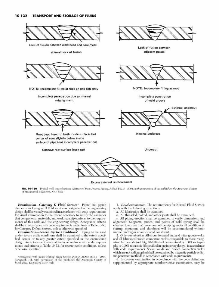
10-132 TRANSPORT AND STORAGE OF FLUIDS
FIG. 10-180 Typical weld imperfections. (Extracted from Process Piping, ASME B31.3—2004, with permission of the publisher, the American Societyof Mechanical Engineers, New York.)
Examination—Category D Fluid Service* Piping and pipingelements for Category D fluid service as designated in the engineeringdesign shall be visually examined in accordance with code requirementsfor visual examination to the extent necessary to satisfy the examinerthat components, materials, and workmanship conform to the require-ments of this code and the engineering design. Acceptance criteriashall be in accordance with code requirements and criteria in Table 10-53,for Category D fluid service, unless otherwise specified.
Examination—Severe Cyclic Conditions* Piping to be usedunder severe cyclic conditions shall be examined to the extent speci-fied herein or to any greater extent specified in the engineeringdesign. Acceptance criteria shall be in accordance with code require-ments and criteria in Table 10-53, for severe cyclic conditions, unlessotherwise specified.
1. Visual examination. The requirements for Normal Fluid Serviceapply with the following exceptions.
a. All fabrication shall be examined.b. All threaded, bolted, and other joints shall be examined.c. All piping erection shall be examined to verify dimensions and
alignment. Supports, guides, and points of cold spring shall bechecked to ensure that movement of the piping under all conditions ofstartup, operation, and shutdown will be accommodated withoutundue binding or unanticipated constraint.
2. Other examination. All circumferential butt and miter groove weldsand all fabricated branch connection welds comparable to those recog-nized by the code (ref. Fig. 10-130) shall be examined by 100% radiogra-phy or 100% ultrasonic (if specified in engineering design) in accordancewith code requirements. Socket welds and branch connection weldswhich are not radiographed shall be examined by magnetic particle or liq-uid penetrant methods in accordance with code requirements.
3. In-process examination in accordance with the code definition,supplemented by appropriate nondestructive examination, may be
*Extracted (with minor editing) from Process Piping, ASME B31.3—2004,paragraph 341, with permission of the publisher, the American Society ofMechanical Engineers, New York.
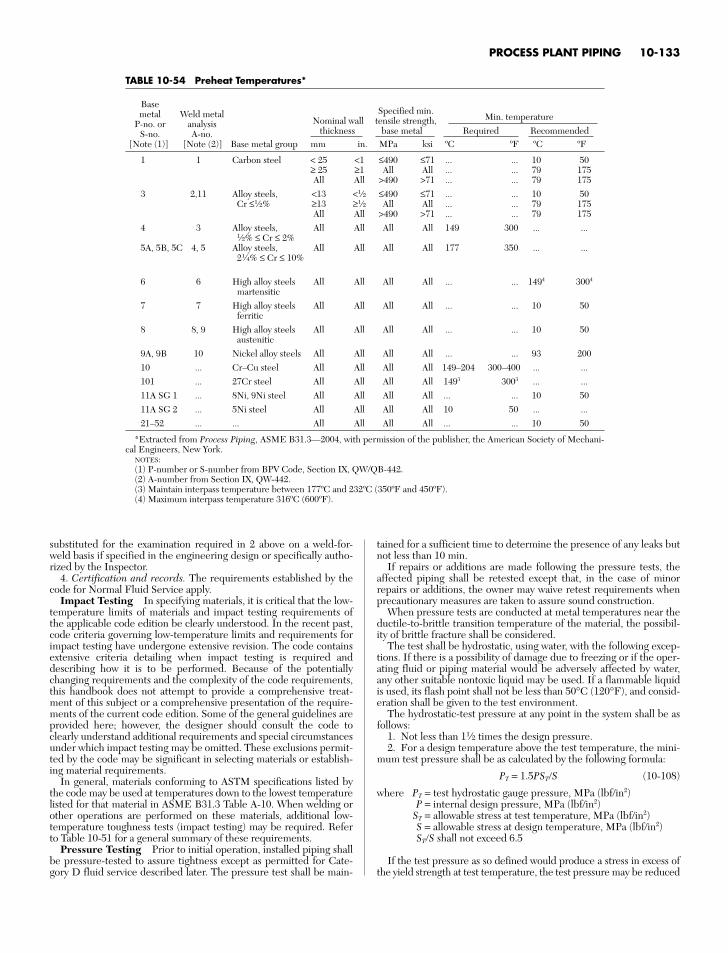
PROCESS PLANT PIPING 10-133
TABLE 10-54 Preheat Temperatures*
Basemetal Weld metal Specified min.
P-no. or analysis Nominal wall tensile strength, Min. temperature
S-no. A-no. thickness base metal Required Recommended[Note (1)] [Note (2)] Base metal group mm in. MPa ksi ºC ºF ºC ºF
1 1 Carbon steel < 25 <1 ≤490 ≤71 ... ... 10 50≥ 25 ≥1 All All ... ... 79 175All All >490 >71 ... ... 79 175
3 2,11 Alloy steels, <13 <1⁄2 ≤490 ≤71 ... ... 10 50Cr ≤1⁄2% ≥13 ≥1⁄2 All All ... ... 79 175
All All >490 >71 ... ... 79 1754 3 Alloy steels, All All All All 149 300 ... ...
1⁄2% ≤ Cr ≤ 2%5A, 5B, 5C 4, 5 Alloy steels, All All All All 177 350 ... ...
21⁄4% ≤ Cr ≤ 10%
6 6 High alloy steels All All All All ... ... 1494 3004
martensitic7 7 High alloy steels All All All All ... ... 10 50
ferritic8 8, 9 High alloy steels All All All All ... ... 10 50
austenitic9A, 9B 10 Nickel alloy steels All All All All ... ... 93 20010 ... Cr–Cu steel All All All All 149–204 300–400 ... ...101 ... 27Cr steel All All All All 1493 3003 ... ...11A SG 1 ... 8Ni, 9Ni steel All All All All ... ... 10 5011A SG 2 ... 5Ni steel All All All All 10 50 ... ...21–52 ... ... All All All All ... ... 10 50
*Extracted from Process Piping, ASME B31.3—2004, with permission of the publisher, the American Society of Mechani-cal Engineers, New York.
NOTES:(1) P-number or S-number from BPV Code, Section IX, QW/QB-442.(2) A-number from Section IX, QW-442.(3) Maintain interpass temperature between 177ºC and 232ºC (350ºF and 450ºF).(4) Maximum interpass temperature 316ºC (600ºF).
substituted for the examination required in 2 above on a weld-for-weld basis if specified in the engineering design or specifically autho-rized by the Inspector.
4. Certification and records. The requirements established by thecode for Normal Fluid Service apply.
Impact Testing In specifying materials, it is critical that the low-temperature limits of materials and impact testing requirements ofthe applicable code edition be clearly understood. In the recent past,code criteria governing low-temperature limits and requirements forimpact testing have undergone extensive revision. The code containsextensive criteria detailing when impact testing is required anddescribing how it is to be performed. Because of the potentiallychanging requirements and the complexity of the code requirements,this handbook does not attempt to provide a comprehensive treat-ment of this subject or a comprehensive presentation of the require-ments of the current code edition. Some of the general guidelines areprovided here; however, the designer should consult the code toclearly understand additional requirements and special circumstancesunder which impact testing may be omitted. These exclusions permit-ted by the code may be significant in selecting materials or establish-ing material requirements.
In general, materials conforming to ASTM specifications listed bythe code may be used at temperatures down to the lowest temperaturelisted for that material in ASME B31.3 Table A-10. When welding orother operations are performed on these materials, additional low-temperature toughness tests (impact testing) may be required. Referto Table 10-51 for a general summary of these requirements.
Pressure Testing Prior to initial operation, installed piping shallbe pressure-tested to assure tightness except as permitted for Cate-gory D fluid service described later. The pressure test shall be main-
tained for a sufficient time to determine the presence of any leaks butnot less than 10 min.
If repairs or additions are made following the pressure tests, theaffected piping shall be retested except that, in the case of minorrepairs or additions, the owner may waive retest requirements whenprecautionary measures are taken to assure sound construction.
When pressure tests are conducted at metal temperatures near theductile-to-brittle transition temperature of the material, the possibil-ity of brittle fracture shall be considered.
The test shall be hydrostatic, using water, with the following excep-tions. If there is a possibility of damage due to freezing or if the oper-ating fluid or piping material would be adversely affected by water,any other suitable nontoxic liquid may be used. If a flammable liquidis used, its flash point shall not be less than 50°C (120°F), and consid-eration shall be given to the test environment.
The hydrostatic-test pressure at any point in the system shall be asfollows:
1. Not less than 11⁄2 times the design pressure.2. For a design temperature above the test temperature, the mini-
mum test pressure shall be as calculated by the following formula:
PT = 1.5PSTS (10-108)
where PT = test hydrostatic gauge pressure, MPa (lbf/in2)P = internal design pressure, MPa (lbf/in2)
ST = allowable stress at test temperature, MPa (lbf/in2)S = allowable stress at design temperature, MPa (lbf/in2)STS shall not exceed 6.5
If the test pressure as so defined would produce a stress in excess ofthe yield strength at test temperature, the test pressure may be reduced
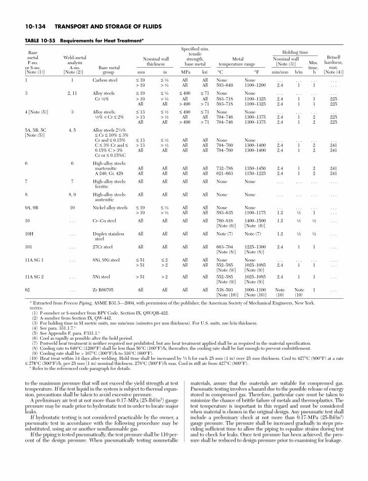
10-134 TRANSPORT AND STORAGE OF FLUIDS
TABLE 10-55 Requirements for Heat Treatment*
BaseSpecified min.
Holding timemetal Weld-metal
tensileBrinell
P-no. analysisNominal wall strength, Metal Nominal wall
Min. hardness,or S-no. A-no. Base metal
thickness base metal temperature range [Note (3)]time, max.
[Note (1)] [Note (2)] group mm in MPa ksi °C °F min/mm h/in h [Note (4)]
1 1 Carbon steel ≤ 19 ≤ e All All None None . . . . . . . . . . . .> 19 > e All All 593–649 1100–1200 2.4 1 1 . . .
3 2, 11 Alloy steels ≤ 19 ≤ e ≤ 490 ≤ 71 None None . . . . . . . . . . . .Cr a% > 19 > e All All 593–718 1100–1325 2.4 1 1 225
All All > 490 > 71 593–718 1100–1325 2.4 1 1 225
4 [Note (5)] 3 Alloy steels, ≤ 13 ≤ a ≤ 490 ≤ 71 None None . . . . . . . . . . . .a% < Cr ≤ 2% > 13 > a All All 704–746 1300–1375 2.4 1 2 225
All All > 490 > 71 704–746 1300–1375 2.4 1 2 225
5A, 5B, 5C 4, 5 Alloy steels 21⁄4%[Note (5)] ≤ Cr ≤ 10% ≤ 3%
Cr and ≤ 0.15% ≤ 13 ≤ a All All None None . . . . . . . . . . . .C ≤ 3% Cr and ≤ > 13 > a All All 704–760 1300–1400 2.4 1 2 2410.15% C > 3% All All All All 704–760 1300–1400 2.4 1 2 241Cr or ≤ 0.15%C
6 6 High-alloy steels:martensitic All All All All 732–788 1350–1450 2.4 1 2 241A 240, Gr. 429 All All All All 621–663 1150–1225 2.4 1 2 241
7 7 High-alloy steels: All All All All None None . . . . . . . . . . . .ferritic
8 8, 9 High-alloy steels: All All All All None None . . . . . . . . . . . .austenitic
9A, 9B 10 Nickel alloy steels ≤ 19 ≤ e All All None None . . . . . . . . . . . .> 19 > e All All 593–635 1100–1175 1.2 a 1 . . .
10 . . . Cr–Cu steel All All All All 760–816 1400–1500 1.2 a a . . .[Note (6)] [Note (6)]
10H . . . Duplex stainless All All All All Note (7) Note (7) 1.2 a a . . .steel
101 . . . 27Cr steel All All All All 663–704 1225–1300 2.4 1 1 . . .[Note (8)] [Note (8)]
11A SG 1 . . . 8Ni, 9Ni steel ≤ 51 ≤ 2 All All None None . . . . . . . . . . . .> 51 > 2 All All 552–585 1025–1085 2.4 1 1 . . .
[Note (9)] [Note (9)]11A SG 2 . . . 5Ni steel > 51 > 2 All All 552–585 1025–1085 2.4 1 1 . . .
[Note (9)] [Note (9)]
62 . . . Zr R60705 All All All All 538–593 1000–1100 Note Note 1 . . .[Note (10)] [Note (10)] (10) (10)
* Extracted from Process Piping, ASME B31.3—2004, with permission of the publisher, the American Society of Mechanical Engineers, New York.NOTES:
(1) P-number or S-number from BPV Code, Section IX, QW/QB-422.(2) A-number from Section IX, QW-442.(3) For holding time in SI metric units, use min/mm (minutes per mm thickness). For U.S. units, use h/in thickness.(4) See para. 331.1.7.a(5) See Appendix F, para. F331.1.a(6) Cool as rapidly as possible after the hold period.(7) Postweld heat treatment is neither required nor prohibited, but any heat treatment applied shall be as required in the material specification.(8) Cooling rate to 649°C (1200°F) shall be less than 56°C (100°F)/h; thereafter, the cooling rate shall be fast enough to prevent embrittlement.(9) Cooling rate shall be > 167°C (300°F)/h to 316°C (600°F).
(10) Heat treat within 14 days after welding. Hold time shall be increased by 1⁄2 h for each 25 mm (1 in) over 25 mm thickness. Cool to 427°C (800°F) at a rate≤ 278°C (500°F)/h, per 25 mm (1 in) nominal thickness, 278°C (500°F)/h max. Cool in still air from 427°C (800°F).
a Refer to the referenced code paragraph for details.
to the maximum pressure that will not exceed the yield strength at testtemperature. If the test liquid in the system is subject to thermal expan-sion, precautions shall be taken to avoid excessive pressure.
A preliminary air test at not more than 0.17-MPa (25-lbf/in2) gaugepressure may be made prior to hydrostatic test in order to locate majorleaks.
If hydrostatic testing is not considered practicable by the owner, apneumatic test in accordance with the following procedure may besubstituted, using air or another nonflammable gas.
If the piping is tested pneumatically, the test pressure shall be 110 per-cent of the design pressure. When pneumatically testing nonmetallic
materials, assure that the materials are suitable for compressed gas.Pneumatic testing involves a hazard due to the possible release of energystored in compressed gas. Therefore, particular care must be taken tominimize the chance of brittle failure of metals and thermoplastics. Thetest temperature is important in this regard and must be consideredwhen material is chosen in the original design. Any pneumatic test shallinclude a preliminary check at not more than 0.17-MPa (25-lbf/in2)gauge pressure. The pressure shall be increased gradually in steps pro-viding sufficient time to allow the piping to equalize strains during testand to check for leaks. Once test pressure has been achieved, the pres-sure shall be reduced to design pressure prior to examining for leakage.

PROCESS PLANT PIPING 10-135
TABLE 10-56 Types of Examination for EvaluatingImperfections*
Type of examination
Liquid-penetrantUltrasonic or
or magnetic-radiographic
Type of imperfection Visual particle Random 100%
Crack X X X XIncomplete penetration X X XLack of fusion X X XWeld undercutting XWeld reinforcement XInternal porosity X XExternal porosity XInternal slag inclusions X XExternal slag inclusions XConcave root surface X X X
*Extracted from the Chemical Plant and Petroleum Refinery Piping Code,ANSI B31.3—1980, with permission of the publisher, the American Society ofMechanical Engineers, New York. For code acceptance criteria (limits on imper-fections) for welds see Table 10-53.
At the owner’s option, a piping system used only for Category Dfluid service as defined in the subsection “Classification of Fluid Ser-vice” may be tested at the normal operating conditions of the systemduring or prior to initial operation by examining for leaks at every jointnot previously tested. A preliminary check shall be made at not morethan 0.17-MPa (25-lbf/in2) gauge pressure when the contained fluid isa gas or a vapor. The pressure shall be increased gradually in steps pro-viding sufficient time to allow the piping to equalize strains duringtesting and to check for leaks.
Tests alternative to those required by these provisions may beapplied under certain conditions described in the code.
Piping required to have a sensitive leak test shall be tested by the gas-and bubble-formation testing method specified in Art. 10, Sec. V of theASME Boiler and Pressure Vessel Code or by another method demon-strated to have equal or greater sensitivity. The sensitivity of the testshall be at least (100 Pa⋅mL)/s [(103 atm⋅mL)/s] under test conditions.
Records shall be kept of each piping installation during the testing.
COST COMPARISON OF PIPING SYSTEMS
Piping may represent as much as 25 percent of the cost of a chemical-process plant. The installed cost of piping systems varies widely with thematerials of construction and the complexity of the system. A study ofpiping costs shows that the most economical choice of material for a sim-ple straight piping run may not be the most economical for a complexinstallation made up of many short runs involving numerous fittings andvalves. The economics also depends heavily on the pipe size and fabrica-tion techniques employed. Fabrication methods such as bending to stan-dard long-radius-elbow dimensions and machine-flaring lap joints have alarge effect on the cost of fabricating pipe from ductile materials suitedto these techniques. Cost reductions of as high as 35 percent are quotedby some custom fabricators utilizing advanced techniques; however, thebasis for pricing comparisons should be carefully reviewed.
Figure 10-181 is based on data extracted from a comparison of theinstalled cost of piping systems of various materials published by theDow Chemical Co. The chart shows the relative cost ratios for systemsof various materials based on two installations, one consisting of 152 m(500 ft) of 2-in pipe in a complex piping arrangement and the other of305 m (1000 ft) of 2-in pipe in a straight-run piping arrangement.Figure 10-181 is based on field-fabrication construction techniquesusing welding stubs, the method commonly used by contractors. Aconsiderably different ranking would result from using other con-struction methods such as machine-formed lap joints and bends inplace of welding elbows. Piping-cost experience shows that it is diffi-cult to generalize and reflect accurate piping-cost comparisons.Although the prices for many of the metallurgies shown in Fig. 10-181are very volatile even over short periods, Fig. 10-181 may still be usedas a reasonable initial estimate of the relative cost of metallic materi-als. The cost of nonmetallic materials and lined metallic materials versus
solid alloy materials should be carefully reviewed prior to materialselection. For an accurate comparison the cost for each type of mate-rial must be estimated individually on the basis of the actual fabrica-tion and installation methods that will be used, pipe sizes and theconditions anticipated for the proposed installation.
FORCES OF PIPING ON PROCESS MACHINERY AND PIPING VIBRATION
The reliability of process rotating machinery is affected by the qualityof the process piping installation. Excessive external forces andmoments upset casing alignment and can reduce clearance betweenmotor and casing. Further, the bearings, seals, and coupling can beadversely affected, resulting in repeated failures that may be correctlydiagnosed as misalignment, and may have excessive piping forces asthe root causes. Most turbine and compressor manufacturers haveprescribed specification or will follow NEMA standards for allowablenozzle loading. For most of the pumps, API or ANSI pump standardswill be followed when evaluating the pump nozzle loads. Pipe supportrestraints need to be placed at the proper locations to protect themachinery nozzles during operation.
Prior to any machinery alignment procedure, it is imperative tocheck for machine pipe strain. This is accomplished by the placementof dial indicators on the shaft and then loosening the hold-down bolts.Movements of greater than 1 mil are considered indication of a pipestrain condition.
This is an important practical problem area, as piping vibration cancause considerable downtime or even pipe failure.
Pipe vibration is caused by:1. Internal flow (pulsation)2. Plant machinery (such as compressors, pumps)Pulsation can be problematic and difficult to predict. Pulsations are
also dependent on acoustic resonance characteristics. For reciprocat-ing equipment, such as reciprocating compressors and pumps, insome cases, an analog (digital) study needs to be performed to identifythe deficiency in the piping and pipe support systems as well as toevaluate the performance of the machine during operation. The studywill also provide recommendations on how to improve the machineand piping system’s performance.
When a pulsation frequency coincides with a mechanical oracoustic resonance, severe vibration can result. A common cause forpulsation is the presence of flow control valves or pressure regulators.These often operate with high pressure drops (i.e., high flow veloci-ties), which can result in the generation of severe pulsation. Flashingand cavitation can also contribute.
Modern-day piping design codes can model the vibration situation,and problems can thus be resolved in the design phases.
HEAT TRACING OF PIPING SYSTEMS
Heat tracing is used to maintain pipes and the material that pipes con-tain at temperatures above the ambient temperature. Two commonuses of heat tracing are preventing water pipes from freezing andmaintaining fuel oil pipes at high enough temperatures such that theviscosity of the fuel oil will allow easy pumping. Heat tracing is alsoused to prevent the condensation of a liquid from a gas and to preventthe solidification of a liquid commodity.
A heat-tracing system is often more expensive on an installed costbasis than the piping system it is protecting, and it will also have sig-nificant operating costs. A study on heat-tracing costs by a majorchemical company showed installed costs of $31/ft to $142/ft andyearly operating costs of $1.40/ft to $16.66/ft. In addition to being amajor cost, the heat-tracing system is an important component of thereliability of a piping system. A failure in the heat-tracing system willoften render the piping system inoperable. For example, with a waterfreeze protection system, the piping system may be destroyed by theexpansion of water as it freezes if the heat-tracing system fails.
The vast majority of heat-traced pipes are insulated to minimizeheat loss to the environment. A heat input of 2 to 10 watts per foot isgenerally required to prevent an insulated pipe from freezing. Withhigh wind speeds, an uninsulated pipe could require well over 100

10-136 TRANSPORT AND STORAGE OF FLUIDS
FIG. 10-181 Cost rankings and cost ratios for various piping materials. This figure is based on field-fabrication construction techniques using welding stubs, asthis is the method most often employed by contractors. A considerably different ranking would result from using other construction methods, such as machined-formed lap joints, for the alloy pipe. °Cost ratio = (cost of listed item)/(cost of Schedule 40 carbon steel piping system, field-fabricated by using welding stubs).(Extracted with permission from Installed Cost of Corrosion Resistant Piping, copyright 1977, Dow Chemical Co.)
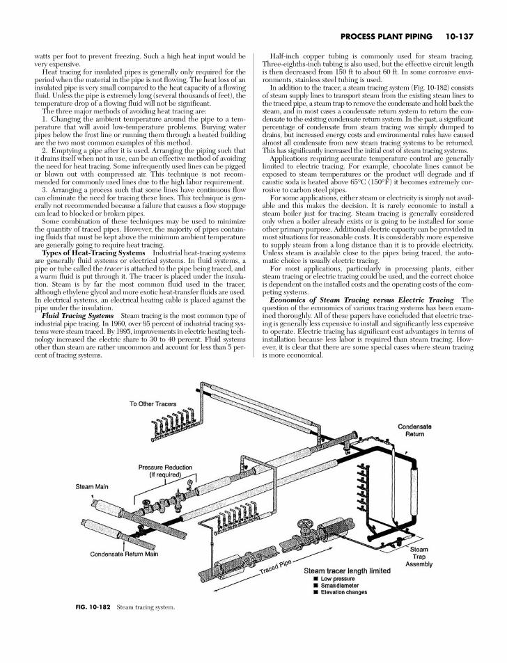
PROCESS PLANT PIPING 10-137
watts per foot to prevent freezing. Such a high heat input would bevery expensive.
Heat tracing for insulated pipes is generally only required for theperiod when the material in the pipe is not flowing. The heat loss of aninsulated pipe is very small compared to the heat capacity of a flowingfluid. Unless the pipe is extremely long (several thousands of feet), thetemperature drop of a flowing fluid will not be significant.
The three major methods of avoiding heat tracing are:1. Changing the ambient temperature around the pipe to a tem-
perature that will avoid low-temperature problems. Burying waterpipes below the frost line or running them through a heated buildingare the two most common examples of this method.
2. Emptying a pipe after it is used. Arranging the piping such thatit drains itself when not in use, can be an effective method of avoidingthe need for heat tracing. Some infrequently used lines can be piggedor blown out with compressed air. This technique is not recom-mended for commonly used lines due to the high labor requirement.
3. Arranging a process such that some lines have continuous flowcan eliminate the need for tracing these lines. This technique is gen-erally not recommended because a failure that causes a flow stoppagecan lead to blocked or broken pipes.
Some combination of these techniques may be used to minimizethe quantity of traced pipes. However, the majority of pipes contain-ing fluids that must be kept above the minimum ambient temperatureare generally going to require heat tracing.
Types of Heat-Tracing Systems Industrial heat-tracing systemsare generally fluid systems or electrical systems. In fluid systems, apipe or tube called the tracer is attached to the pipe being traced, anda warm fluid is put through it. The tracer is placed under the insula-tion. Steam is by far the most common fluid used in the tracer,although ethylene glycol and more exotic heat-transfer fluids are used.In electrical systems, an electrical heating cable is placed against thepipe under the insulation.
Fluid Tracing Systems Steam tracing is the most common type ofindustrial pipe tracing. In 1960, over 95 percent of industrial tracing sys-tems were steam traced. By 1995, improvements in electric heating tech-nology increased the electric share to 30 to 40 percent. Fluid systemsother than steam are rather uncommon and account for less than 5 per-cent of tracing systems.
Half-inch copper tubing is commonly used for steam tracing.Three-eighths-inch tubing is also used, but the effective circuit lengthis then decreased from 150 ft to about 60 ft. In some corrosive envi-ronments, stainless steel tubing is used.
In addition to the tracer, a steam tracing system (Fig. 10-182) consistsof steam supply lines to transport steam from the existing steam lines tothe traced pipe, a steam trap to remove the condensate and hold back thesteam, and in most cases a condensate return system to return the con-densate to the existing condensate return system. In the past, a significantpercentage of condensate from steam tracing was simply dumped todrains, but increased energy costs and environmental rules have causedalmost all condensate from new steam tracing systems to be returned.This has significantly increased the initial cost of steam tracing systems.
Applications requiring accurate temperature control are generallylimited to electric tracing. For example, chocolate lines cannot beexposed to steam temperatures or the product will degrade and ifcaustic soda is heated above 65°C (150°F) it becomes extremely cor-rosive to carbon steel pipes.
For some applications, either steam or electricity is simply not avail-able and this makes the decision. It is rarely economic to install asteam boiler just for tracing. Steam tracing is generally consideredonly when a boiler already exists or is going to be installed for someother primary purpose. Additional electric capacity can be provided inmost situations for reasonable costs. It is considerably more expensiveto supply steam from a long distance than it is to provide electricity.Unless steam is available close to the pipes being traced, the auto-matic choice is usually electric tracing.
For most applications, particularly in processing plants, eithersteam tracing or electric tracing could be used, and the correct choiceis dependent on the installed costs and the operating costs of the com-peting systems.
Economics of Steam Tracing versus Electric Tracing Thequestion of the economics of various tracing systems has been exam-ined thoroughly. All of these papers have concluded that electric trac-ing is generally less expensive to install and significantly less expensiveto operate. Electric tracing has significant cost advantages in terms ofinstallation because less labor is required than steam tracing. How-ever, it is clear that there are some special cases where steam tracingis more economical.
FIG. 10-182 Steam tracing system.
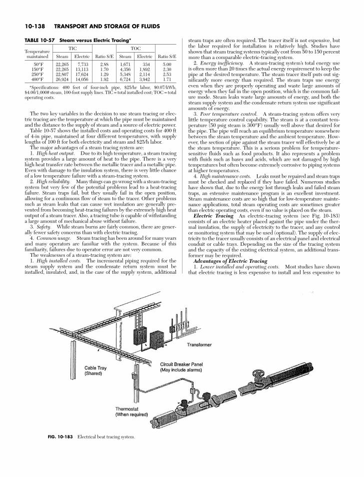
The two key variables in the decision to use steam tracing or elec-tric tracing are the temperature at which the pipe must be maintainedand the distance to the supply of steam and a source of electric power.
Table 10-57 shows the installed costs and operating costs for 400 ftof 4-in pipe, maintained at four different temperatures, with supplylengths of 100 ft for both electricity and steam and $25/h labor.
The major advantages of a steam tracing system are:1. High heat output. Due to its high temperature, a steam tracing
system provides a large amount of heat to the pipe. There is a veryhigh heat transfer rate between the metallic tracer and a metallic pipe.Even with damage to the insulation system, there is very little chanceof a low temperature failure with a steam-tracing system.
2. High reliability. Many things can go wrong with a steam-tracingsystem but very few of the potential problems lead to a heat-tracingfailure. Steam traps fail, but they usually fail in the open position,allowing for a continuous flow of steam to the tracer. Other problemssuch as steam leaks that can cause wet insulation are generally pre-vented from becoming heat-tracing failures by the extremely high heatoutput of a steam tracer. Also, a tracing tube is capable of withstandinga large amount of mechanical abuse without failure.
3. Safety. While steam burns are fairly common, there are gener-ally fewer safety concerns than with electric tracing.
4. Common usage. Steam tracing has been around for many yearsand many operators are familiar with the system. Because of thisfamiliarity, failures due to operator error are not very common.
The weaknesses of a steam-tracing system are:1. High installed costs. The incremental piping required for the
steam supply system and the condensate return system must beinstalled, insulated, and, in the case of the supply system, additional
steam traps are often required. The tracer itself is not expensive, butthe labor required for installation is relatively high. Studies haveshown that steam tracing systems typically cost from 50 to 150 percentmore than a comparable electric-tracing system.
2. Energy inefficiency. A steam-tracing system’s total energy useis often more than 20 times the actual energy requirement to keep thepipe at the desired temperature. The steam tracer itself puts out sig-nificantly more energy than required. The steam traps use energyeven when they are properly operating and waste large amounts ofenergy when they fail in the open position, which is the common fail-ure mode. Steam leaks waste large amounts of energy, and both thesteam supply system and the condensate return system use significantamounts of energy.
3. Poor temperature control. A steam-tracing system offers verylittle temperature control capability. The steam is at a constant tem-perature (50 psig steam is 300°F) usually well above that desired forthe pipe. The pipe will reach an equilibrium temperature somewherebetween the steam temperature and the ambient temperature. How-ever, the section of pipe against the steam tracer will effectively be atthe steam temperature. This is a serious problem for temperature-sensitive fluids such as food products. It also represents a problemwith fluids such as bases and acids, which are not damaged by hightemperatures but often become extremely corrosive to piping systemsat higher temperatures.
4. High maintenance costs. Leaks must be repaired and steam trapsmust be checked and replaced if they have failed. Numerous studieshave shown that, due to the energy lost through leaks and failed steamtraps, an extensive maintenance program is an excellent investment.Steam maintenance costs are so high that for low-temperature mainte-nance applications, total steam operating costs are sometimes greaterthan electric operating costs, even if no value is placed on the steam.
Electric Tracing An electric-tracing system (see Fig. 10-183)consists of an electric heater placed against the pipe under the ther-mal insulation, the supply of electricity to the tracer, and any controlor monitoring system that may be used (optional). The supply of elec-tricity to the tracer usually consists of an electrical panel and electricalconduit or cable trays. Depending on the size of the tracing systemand the capacity of the existing electrical system, an additional trans-former may be required.
Advantages of Electric Tracing1. Lower installed and operating costs. Most studies have shown
that electric tracing is less expensive to install and less expensive to
10-138 TRANSPORT AND STORAGE OF FLUIDS
TABLE 10-57 Steam versus Electric Tracing*
TemperatureTIC TOC
maintained Steam Electric Ratio S/E Steam Electric Ratio S/E
50°F 22,265 7,733 2.88 1,671 334 5.00150°F 22,265 13,113 1.70 4,356 1,892 2.30250°F 22,807 17,624 1.29 5,348 2,114 2.53400°F 26,924 14,056 1.92 6,724 3,942 1.71
*Specifications: 400 feet of four-inch pipe, $25/hr labor, $0.07/kWh,$4.00/1,000# steam, 100-foot supply lines. TIC = total installed cost; TOC = totaloperating costs.
FIG. 10-183 Electrical beat tracing system.
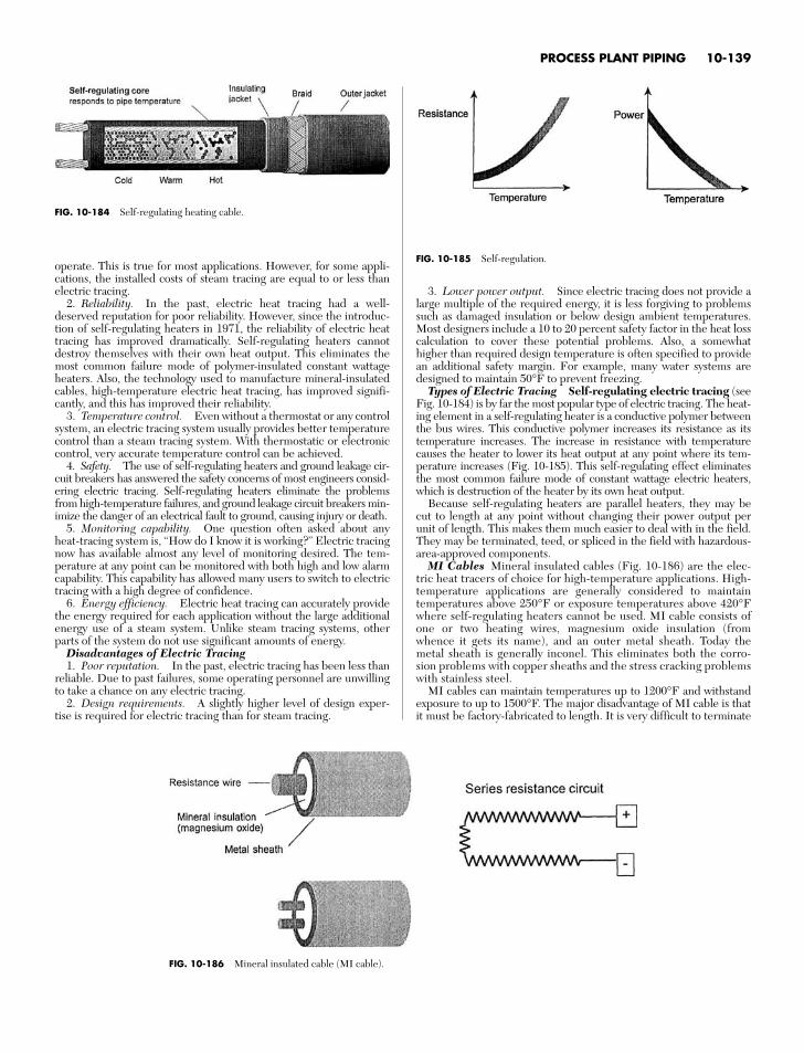
PROCESS PLANT PIPING 10-139
operate. This is true for most applications. However, for some appli-cations, the installed costs of steam tracing are equal to or less thanelectric tracing.
2. Reliability. In the past, electric heat tracing had a well-deserved reputation for poor reliability. However, since the introduc-tion of self-regulating heaters in 1971, the reliability of electric heattracing has improved dramatically. Self-regulating heaters cannotdestroy themselves with their own heat output. This eliminates themost common failure mode of polymer-insulated constant wattageheaters. Also, the technology used to manufacture mineral-insulatedcables, high-temperature electric heat tracing, has improved signifi-cantly, and this has improved their reliability.
3. Temperature control. Even without a thermostat or any controlsystem, an electric tracing system usually provides better temperaturecontrol than a steam tracing system. With thermostatic or electroniccontrol, very accurate temperature control can be achieved.
4. Safety. The use of self-regulating heaters and ground leakage cir-cuit breakers has answered the safety concerns of most engineers consid-ering electric tracing. Self-regulating heaters eliminate the problemsfrom high-temperature failures, and ground leakage circuit breakers min-imize the danger of an electrical fault to ground, causing injury or death.
5. Monitoring capability. One question often asked about anyheat-tracing system is, “How do I know it is working?” Electric tracingnow has available almost any level of monitoring desired. The tem-perature at any point can be monitored with both high and low alarmcapability. This capability has allowed many users to switch to electrictracing with a high degree of confidence.
6. Energy efficiency. Electric heat tracing can accurately providethe energy required for each application without the large additionalenergy use of a steam system. Unlike steam tracing systems, otherparts of the system do not use significant amounts of energy.
Disadvantages of Electric Tracing1. Poor reputation. In the past, electric tracing has been less than
reliable. Due to past failures, some operating personnel are unwillingto take a chance on any electric tracing.
2. Design requirements. A slightly higher level of design exper-tise is required for electric tracing than for steam tracing.
3. Lower power output. Since electric tracing does not provide alarge multiple of the required energy, it is less forgiving to problemssuch as damaged insulation or below design ambient temperatures.Most designers include a 10 to 20 percent safety factor in the heat losscalculation to cover these potential problems. Also, a somewhathigher than required design temperature is often specified to providean additional safety margin. For example, many water systems aredesigned to maintain 50°F to prevent freezing.
Types of Electric Tracing Self-regulating electric tracing (seeFig. 10-184) is by far the most popular type of electric tracing. The heat-ing element in a self-regulating heater is a conductive polymer betweenthe bus wires. This conductive polymer increases its resistance as itstemperature increases. The increase in resistance with temperaturecauses the heater to lower its heat output at any point where its tem-perature increases (Fig. 10-185). This self-regulating effect eliminatesthe most common failure mode of constant wattage electric heaters,which is destruction of the heater by its own heat output.
Because self-regulating heaters are parallel heaters, they may becut to length at any point without changing their power output perunit of length. This makes them much easier to deal with in the field.They may be terminated, teed, or spliced in the field with hazardous-area-approved components.
MI Cables Mineral insulated cables (Fig. 10-186) are the elec-tric heat tracers of choice for high-temperature applications. High-temperature applications are generally considered to maintaintemperatures above 250°F or exposure temperatures above 420°Fwhere self-regulating heaters cannot be used. MI cable consists ofone or two heating wires, magnesium oxide insulation (fromwhence it gets its name), and an outer metal sheath. Today themetal sheath is generally inconel. This eliminates both the corro-sion problems with copper sheaths and the stress cracking problemswith stainless steel.
MI cables can maintain temperatures up to 1200°F and withstandexposure to up to 1500°F. The major disadvantage of MI cable is thatit must be factory-fabricated to length. It is very difficult to terminate
FIG. 10-184 Self-regulating heating cable.
FIG. 10-185 Self-regulation.
FIG. 10-186 Mineral insulated cable (MI cable).
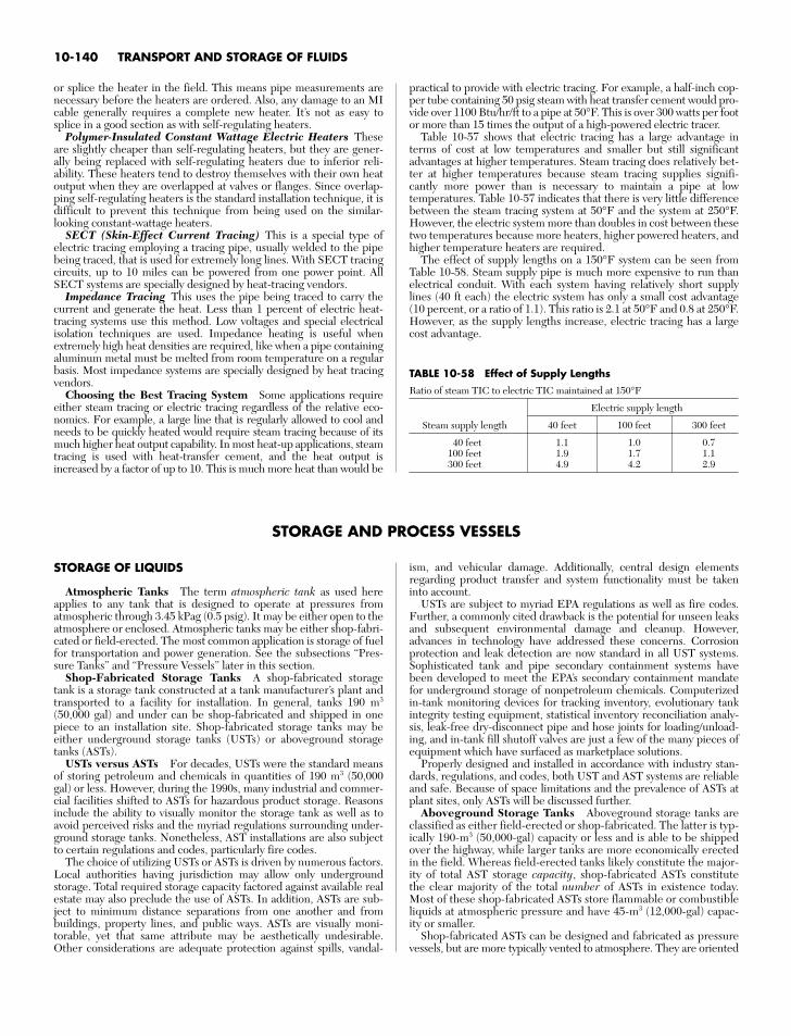
10-140 TRANSPORT AND STORAGE OF FLUIDS
or splice the heater in the field. This means pipe measurements arenecessary before the heaters are ordered. Also, any damage to an MIcable generally requires a complete new heater. It’s not as easy tosplice in a good section as with self-regulating heaters.
Polymer-Insulated Constant Wattage Electric Heaters Theseare slightly cheaper than self-regulating heaters, but they are gener-ally being replaced with self-regulating heaters due to inferior reli-ability. These heaters tend to destroy themselves with their own heatoutput when they are overlapped at valves or flanges. Since overlap-ping self-regulating heaters is the standard installation technique, it isdifficult to prevent this technique from being used on the similar-looking constant-wattage heaters.
SECT (Skin-Effect Current Tracing) This is a special type ofelectric tracing employing a tracing pipe, usually welded to the pipebeing traced, that is used for extremely long lines. With SECT tracingcircuits, up to 10 miles can be powered from one power point. AllSECT systems are specially designed by heat-tracing vendors.
Impedance Tracing This uses the pipe being traced to carry thecurrent and generate the heat. Less than 1 percent of electric heat-tracing systems use this method. Low voltages and special electricalisolation techniques are used. Impedance heating is useful whenextremely high heat densities are required, like when a pipe containingaluminum metal must be melted from room temperature on a regularbasis. Most impedance systems are specially designed by heat tracingvendors.
Choosing the Best Tracing System Some applications requireeither steam tracing or electric tracing regardless of the relative eco-nomics. For example, a large line that is regularly allowed to cool andneeds to be quickly heated would require steam tracing because of itsmuch higher heat output capability. In most heat-up applications, steamtracing is used with heat-transfer cement, and the heat output isincreased by a factor of up to 10. This is much more heat than would be
practical to provide with electric tracing. For example, a half-inch cop-per tube containing 50 psig steam with heat transfer cement would pro-vide over 1100 Btu/hr/ft to a pipe at 50°F. This is over 300 watts per footor more than 15 times the output of a high-powered electric tracer.
Table 10-57 shows that electric tracing has a large advantage interms of cost at low temperatures and smaller but still significantadvantages at higher temperatures. Steam tracing does relatively bet-ter at higher temperatures because steam tracing supplies signifi-cantly more power than is necessary to maintain a pipe at lowtemperatures. Table 10-57 indicates that there is very little differencebetween the steam tracing system at 50°F and the system at 250°F.However, the electric system more than doubles in cost between thesetwo temperatures because more heaters, higher powered heaters, andhigher temperature heaters are required.
The effect of supply lengths on a 150°F system can be seen fromTable 10-58. Steam supply pipe is much more expensive to run thanelectrical conduit. With each system having relatively short supplylines (40 ft each) the electric system has only a small cost advantage(10 percent, or a ratio of 1.1). This ratio is 2.1 at 50°F and 0.8 at 250°F.However, as the supply lengths increase, electric tracing has a largecost advantage.
TABLE 10-58 Effect of Supply Lengths
Ratio of steam TIC to electric TIC maintained at 150°F
Electric supply length
Steam supply length 40 feet 100 feet 300 feet
40 feet 1.1 1.0 0.7100 feet 1.9 1.7 1.1300 feet 4.9 4.2 2.9
ism, and vehicular damage. Additionally, central design elementsregarding product transfer and system functionality must be takeninto account.
USTs are subject to myriad EPA regulations as well as fire codes.Further, a commonly cited drawback is the potential for unseen leaksand subsequent environmental damage and cleanup. However,advances in technology have addressed these concerns. Corrosionprotection and leak detection are now standard in all UST systems.Sophisticated tank and pipe secondary containment systems havebeen developed to meet the EPA’s secondary containment mandatefor underground storage of nonpetroleum chemicals. Computerizedin-tank monitoring devices for tracking inventory, evolutionary tankintegrity testing equipment, statistical inventory reconciliation analy-sis, leak-free dry-disconnect pipe and hose joints for loading/unload-ing, and in-tank fill shutoff valves are just a few of the many pieces ofequipment which have surfaced as marketplace solutions.
Properly designed and installed in accordance with industry stan-dards, regulations, and codes, both UST and AST systems are reliableand safe. Because of space limitations and the prevalence of ASTs atplant sites, only ASTs will be discussed further.
Aboveground Storage Tanks Aboveground storage tanks areclassified as either field-erected or shop-fabricated. The latter is typ-ically 190-m3 (50,000-gal) capacity or less and is able to be shippedover the highway, while larger tanks are more economically erectedin the field. Whereas field-erected tanks likely constitute the major-ity of total AST storage capacity, shop-fabricated ASTs constitutethe clear majority of the total number of ASTs in existence today.Most of these shop-fabricated ASTs store flammable or combustibleliquids at atmospheric pressure and have 45-m3 (12,000-gal) capac-ity or smaller.
Shop-fabricated ASTs can be designed and fabricated as pressurevessels, but are more typically vented to atmosphere. They are oriented
STORAGE AND PROCESS VESSELS
STORAGE OF LIQUIDS
Atmospheric Tanks The term atmospheric tank as used hereapplies to any tank that is designed to operate at pressures fromatmospheric through 3.45 kPag (0.5 psig). It may be either open to theatmosphere or enclosed. Atmospheric tanks may be either shop-fabri-cated or field-erected. The most common application is storage of fuelfor transportation and power generation. See the subsections “Pres-sure Tanks” and “Pressure Vessels” later in this section.
Shop-Fabricated Storage Tanks A shop-fabricated storagetank is a storage tank constructed at a tank manufacturer’s plant andtransported to a facility for installation. In general, tanks 190 m3
(50,000 gal) and under can be shop-fabricated and shipped in onepiece to an installation site. Shop-fabricated storage tanks may beeither underground storage tanks (USTs) or aboveground storagetanks (ASTs).
USTs versus ASTs For decades, USTs were the standard meansof storing petroleum and chemicals in quantities of 190 m3 (50,000gal) or less. However, during the 1990s, many industrial and commer-cial facilities shifted to ASTs for hazardous product storage. Reasonsinclude the ability to visually monitor the storage tank as well as toavoid perceived risks and the myriad regulations surrounding under-ground storage tanks. Nonetheless, AST installations are also subjectto certain regulations and codes, particularly fire codes.
The choice of utilizing USTs or ASTs is driven by numerous factors.Local authorities having jurisdiction may allow only undergroundstorage. Total required storage capacity factored against available realestate may also preclude the use of ASTs. In addition, ASTs are sub-ject to minimum distance separations from one another and frombuildings, property lines, and public ways. ASTs are visually moni-torable, yet that same attribute may be aesthetically undesirable.Other considerations are adequate protection against spills, vandal-
STORAGE AND PROCESS VESSELS 10-141
for either horizontal or vertical installation and are made in eithercylindrical or rectangular form. Tanks are often secondarily con-tained and may also include insulation for fire safety or temperaturecontrol. Compartmented ASTs are also available. Over 90 percent ofthe atmospheric tank applications store some sort of hydrocarbon.Within that, a majority are used to store fuels for motor vehicle dis-pensing.
Fire Codes Many chemicals are classified as either flammable orcombustible or subject to fire codes. All hydrocarbon tanks are classi-fied as flammable or combustible. Notably, with the tremendousincrease in the use of ASTs at private fleet fueling facilities in the1990s, fire codes were rapidly modified to address the understandablesafety concerns. In the United States, two principal organizations pub-lish fire codes pertinent to underground storage tanks, with each stateadopting all or part of the respective codes.
The National Fire Protection Association (NFPA) has devel-oped several principal codes pertaining to the storage of flammableand combustible liquids:
NFPA 30, Flammable and Combustible Liquids Code (2003)NFPA 30A, Code for Motor Fuel Dispensing Facilities and
Repair Garages (2003)NFPA 31, Standard for the Installation of Oil Burning Equip-
mentThe International Code Council (ICC) was formed by the con-
solidation of three formerly separate fire code organizations: Interna-tional Conference of Building Officials (ICBO), which had publishedthe Uniform Fire Code under its fire service arm, the InternationalFire Code Institute (IFCI); Building Officials and Code Administra-tors (BOCA), which had published the National Fire PreventionCode; and Southern Building Congress Code International (SBCCI),which had published the Standard Fire Prevention Code. When thethree groups merged in 2000, in part to develop a common fire code,the individual codes became obsolete; however, they are noted abovesince references to them may periodically surface. The consolidatedcode is IFC-2006, International Fire Code.
The Canadian Commission on Building and Fire Codes(CCBFC) developed a recommended model code to permit adoptionby various regional authorities. The National Research Council ofCanada publishes the model code document National Fire Code ofCanada (1995).
Standards Third-party standards for AST fabrication haveevolved significantly over the past two decades, as have various rec-ommended practice guidelines for the installation and operations ofAST systems. Standards developed by Underwriters Laboratories(UL) have been perhaps the most predominant guidelines—in fact,ASTs are often categorized according to the UL standard that theymeet, such as “a UL 142 tank.”
Underwriters Laboratories Inc. standards for steel ASTs storingflammable and combustible liquids include the following:
UL 142, Steel Aboveground Tanks for Flammable and Com-bustible Liquids, 9th ed., covers steel atmospheric tanks intendedfor aboveground storage of noncorrosive, stable, flammable, and com-bustible liquids that have a specific gravity not exceeding that of water.UL 142 applies to single-wall and double-wall horizontal carbon-steeland stainless steel tanks up to 190 m3 (50,000 gal), with a maximumdiameter of 3.66 m (12 ft) and a maximum length-to-diameter ratio of8 : 1. A formula from Roark’s Formulas for Stress and Strain has beenincorporated within UL 58 to calculate minimum steel wall thick-nesses. UL 142 also applies to vertical tanks up to 10.7 m (35 ft) inheight. UL 142 has been the primary AST standard since its develop-ment in 1922.
Tanks covered by these requirements can be fabricated in cylindri-cal or rectangular configurations. The standard covers secondary con-tained tanks, either of dual-wall construction or a tank in a steel dikeor bund. It also provides listings for special AST constructions, such asthose used under generators for backup power. These tanks are fabri-cated, inspected, and tested for leakage before shipment from the fac-tory as completely assembled vessels.
UL 142 provides details for steel type, wall thickness, compart-ments and bulkheads, manways, and other fittings and appurtenances.Issues relating to leakage, venting, and the ability of the tank to with-
stand the development of internal pressures encountered duringoperation and production leak testing are also addressed.
These requirements do not apply to large field-erected storagetanks covered by the Standard for Welded Steel Tanks for Oil Storage,ANSI/API 650, or the Specification for Field-Welded Tanks for Stor-age of Production Liquids, API 12D; or to the Specification for Shop-Welded Tanks for Storage of Production Liquids, API 12F.
UL 2085, Protected Aboveground Tanks for Flammable andCombustible Liquids, covers shop-fabricated, aboveground atmos-pheric protected tanks intended for storage of stable, flammable orcombustible liquids that have a specific gravity not greater than 1.0 andthat are compatible with the material and construction of the tank.
The UL 2085 tank construction is intended to limit the heat trans-ferred to the primary tank when the AST is exposed to a 2-h hydro-carbon pool fire of 1093oC (2000oF). The tank must be insulated towithstand the test without leakage and with an average maximumtemperature rise on the primary tank not exceeding 127oC (260oF).Temperatures on the inside surface of the primary tank cannot exceed204oC (400oF).
UL 2085 also provides criteria for resistance against vehicle impact,ballistic impact, and fire hose impact. These tanks are also providedwith integral secondary containment intended to prevent any leakagefrom the primary tank from entering the environment.
UL 2080, Fire Resistant Tanks for Flammable and Com-bustible Liquids, is similar to UL 2085 tanks, except with an averagemaximum temperature rise on the primary tank limited to 427oC(800oF) during a 2-h pool fire. Temperatures on the inside surface ofthe primary tank cannot exceed 538oC (1000oF).
UL 2244, Standard for Aboveground Flammable LiquidTank Systems, covers factory-fabricated, preengineered above-ground atmospheric tank systems intended for dispensing flammableor combustible liquids, such as gasoline or diesel fuel, into motor vehi-cles, generators, or aircraft.
UL 80, Steel Tanks for Oil-Burner Fuel, covers the design andconstruction of welded steel tanks of the atmospheric type with a max-imum capacity of 0.23 to 2.5 m3 (60 to 660 gal) intended for unen-closed installation inside of buildings or for outside abovegroundapplications as permitted by the Standard for Installation of Oil-Burn-ing Equipment, NFPA 31, primarily for the storage and supply of fueloil for oil burners.
UL 2245, Below-Grade Vaults for Flammable Liquid StorageTanks, covers below-grade vaults intended for the storage of flamma-ble or combustible liquids in an aboveground atmospheric tank.Below-grade vaults, constructed of a minimum of 150 mm (6 in) ofreinforced concrete or other equivalent noncombustible material, aredesigned to contain one aboveground tank, which can be a compart-ment tank. Adjacent vaults may share a common wall. The lid of thevault may be at grade or below. Vaults provide a safe means to installhazardous tanks so that the system is accessible to the operator with-out unduly exposing the public.
Southwest Research Institute (SwRI) standards for steel ASTsstoring flammable and combustible liquids include the following:
SwRI 93-01, Testing Requirements for Protected Above-ground Flammable Liquid/Fuel Storage Tanks, includes tests toevaluate the performance of ASTs under fire, hose stream, ballistics,heavy vehicular impact, and different environments. This standardrequires pool-fire resistance similar to that of UL 2085.
SwRI 97-04, Standard for Fire Resistant Tanks, includes teststo evaluate the performance of ASTs under fire and hose stream. Thisstandard is similar to UL 2080 in that the construction is exposed to a2-h hydrocarbon pool fire of 1093oC (2000oF). However, SwRI 97-04is concerned only with the integrity of the tank after the 2-h test andnot concerned with the temperature inside the tank due to the heattransfer. As a result, UL 142 tanks have been tested to the SwRI stan-dard and passed. Secondary containment with insulation is not neces-sarily an integral component of the system.
Underwriters Laboratories of Canada (ULC) publishes a num-ber of standards for aboveground tanks and accessories. All the fol-lowing pertain to the aboveground storage of flammable liquids andcombustible liquids such as gasoline, fuel oil, or similar products witha relative density not greater than 1.0:
ULC S601, Shop Fabricated Steel Aboveground HorizontalTanks for Flammable and Combustible Liquids, covers single-and double-wall cylindrical horizontal steel nonpressure tanks. Theserequirements do not cover tanks of capacities greater than 200 m3.
ULC S630, Shop Fabricated Steel Aboveground VerticalTanks for Flammable and Combustible Liquids, covers single-and double-wall cylindrical vertical steel nonpressure tanks.
ULC S643, Shop Fabricated Steel Utility Tanks for Flamma-ble and Combustible Liquids, covers single- and double-wall cylin-drical horizontal steel nonpressure tanks.
ULC S653-94, Aboveground Steel Contained Tank Assem-blies for Flammable and Combustible Liquids, covers steel con-tained tank assemblies.
ULC S655, Aboveground Protected Tank Assemblies forFlammable and Combustible Liquids, covers shop-fabricated pri-mary tanks that provided with secondary containment and protectiveencasement and are intended for stationary installation and use inaccordance with
1. National Fire Code of Canada, Part 42. CAN/CSA-B139, Installation Code for Oil Burning Equipment3. The Environmental Code of Practice for Aboveground Storage
Tank Systems Containing Petroleum Products4. The requirements of the authority having jurisdictionULC/ORD C142.20, Secondary Containment for Above-
ground Flammable and Combustible Liquid Storage Tanks,covers secondary containments for aboveground primary tanks.
ULC S602, Aboveground Steel Tanks for the Storage ofCombustible Liquids Intended to Be Used as Heating and/orGenerator Fuels, covers the design and construction of tanks of thenonpressure type, intended for installation inside or outside buildings.This standard covers single-wall tanks and tanks with secondary con-tainment, having a maximum capacity of 2.5 m3.
The Petroleum Equipment Institute (PEI) has developed a rec-ommended practice for AST system installation: PEI-RP200, RP200, Recommended Practices for Installation of AbovegroundStorage Systems for Motor Vehicle Fueling.
The American Petroleum Institute (API) has developed a seriesof standards and specifications involving ASTs:
API 12F, Shop Welded Tanks for Storage of Production LiquidsRP 12R1, Setting, Maintenance, Inspection, Operation, and
Repair of Tanks in Production ServiceRP 575, Inspection of Atmospheric and Low Pressure Storage
TanksRP 579, Fitness-For-ServiceAPI 650, Welded Steel Tanks for Oil StorageAPI 652, Lining of Aboveground Storage Tank BottomsAPI 653, Tank Inspection, Repair, Alteration, and
ReconstructionAPI 2350, Overfill Protection for Storage Tanks in Petroleum
Facilities (overfill is the primary cause of AST releases)The American Society of Mechanical Engineers (ASME) has
developed a standard for welded aluminum-alloy storage tanks:B96.1, Welded Aluminum-Alloy Storage Tanks (1999), covers thedesign, materials, fabrication, erection, inspection, and testingrequirements for welded aluminum alloy (field-erected or shop-fabri-cated) aboveground, vertical, cylindrical, flat bottom, open or closed-top tanks storing liquids under pressures approximating atmosphericpressure at ambient temperatures.
The American Water Works Association (AWWA) has many stan-dards dealing with water handling and storage. A list of its publications isgiven in the AWWA Handbook (annually). AWWA D100, Standard forSteel Tanks—Standpipes, Reservoirs, and Elevated Tanks for WaterStorage, contains rules for design and fabrication. Although AWWA tanksare intended for water, they could be used for the storage of other liquids.
The Steel Tank Institute (STI) publishes construction standardsand recommended installation practices pertaining to ASTs fabricatedto STI technologies. STI’s recommended installation practices arenotable for their applicability to similar respective technologies:
SP001-06, Standard for Inspection of In-Service Shop Fabricated Aboveground Tanks for Storage of Combustibleand Flammable Liquids
R912-00, Installation Instructions for Shop Fabricated Aboveground Storage Tanks for Flammable, CombustibleLiquids
F921, Standard for Aboveground Tanks with Integral Secondary Containment
Standard for Fire Resistant Tanks (Flameshield)Standard for Fireguard Thermally Insulated Aboveground
Storage TanksF911, Standard for Diked Aboveground Storage TanksThe National Association of Corrosion Engineers (NACE
International) has developed the following to protect the soil side ofbottoms of on-grade carbon-steel storage tanks: NACE RP0193-01,Standard Recommended Practice—External Cathodic Protec-tion of On-Grade Metallic Storage Tank Bottoms.
Environmental Regulations A key United States Environ-mental Protection Agency (US EPA) requirement for certainaboveground storage facilities is the development and submittal ofSpill Prevention Control and Countermeasure (SPCC) Plans within40 CFR 112, the Oil Pollution Prevention regulation, which in turn ispart of the Clean Water Act (CWA). SPCC Plans and FacilityResponse Plans pertain to facilities which may discharge oil intogroundwater or storm runoff, which in turn may flow into navigablewaters. Enacted in 1973, these requirements were principally used byowners of large, field-fabricated aboveground tanks predominant atthat time, although the regulation applied to all bulk containers largerthan 2.5 m3 (660 gal) and included the requirement for a ProfessionalEngineer to certify the spill plan.
In July 2002, the US EPA issued a final rule amending 40 CFR 112which included differentiation of shop-fabricated from field-fabri-cated ASTs. The rule also includes new subparts outlining the require-ments for various classes of oil, revises the applicability of theregulation, amends the requirements for completing SPCC Plans, andmakes other modifications.
The revised rule also states that all bulk storage container installa-tions must provide a secondary means of containment for the entirecapacity of the largest single container, with sufficient freeboard tocontain precipitation, and that such containment is sufficiently imper-vious to contain discharged oil. US EPA encourages the use of industrystandards to comply with the rules. Many owners of shop-fabricatedtanks have opted for double-wall tanks built to STI or UL standards asa means to comply with this requirement.
State and Local Jurisdictions Due to the manner in which above-ground storage tank legislation was promulgated in 1972 for protectionof surface waters from oil pollution, state environmental agencies did notreceive similar jurisdiction as they did within the underground storagetank rules. Nonetheless, many state environmental agencies, state firemarshals, or Weights and Measures departments—including Minnesota,Florida, Wisconsin, Virginia, Oklahoma, Missouri, Maryland, Delaware,and Michigan—are presently regulating aboveground storage tanksthrough other means. Other regulations exist for hazardous chemicalsand should be consulted for specific requirements.
Aboveground Storage Tank Types and Options Most hydro-carbon storage applications use carbon steel as the most economicaland available material that provides suitable strength and compatibil-ity for the specific storage application. For vertical tanks installed ongrade, corrosion protection can be given to exterior tank bottoms incontact with soil. The interior of the tank can incorporate special coat-ings and linings (e.g., polymer, glass, or other metals). Some chemicalstorage applications will dictate that the storage tank be made from astainless steel or nickel alloy. Fiberglass-reinforced plastic (FRP),polyethylene, or polypropylene may be used for nonflammable stor-age in smaller sizes. Suppliers can be contacted to verify the appropri-ate material to be used.
As stated earlier, shop-fabricated ASTs are often categorized accord-ing to the standards to which the tanks are fabricated, e.g., a UL 142 orUL 2085 tank. That said, however, there are defined categories such asdiked tanks, protected tanks, fire-resistant tanks, and insulated tanks.It’s critical, then, for the tank buyer or specifier to know precisely whatis required or desired given the application, code requirements, and/orowner/operator preferences—and to discuss this with the tank con-tractor and/or manufacturer.
10-142 TRANSPORT AND STORAGE OF FLUIDS
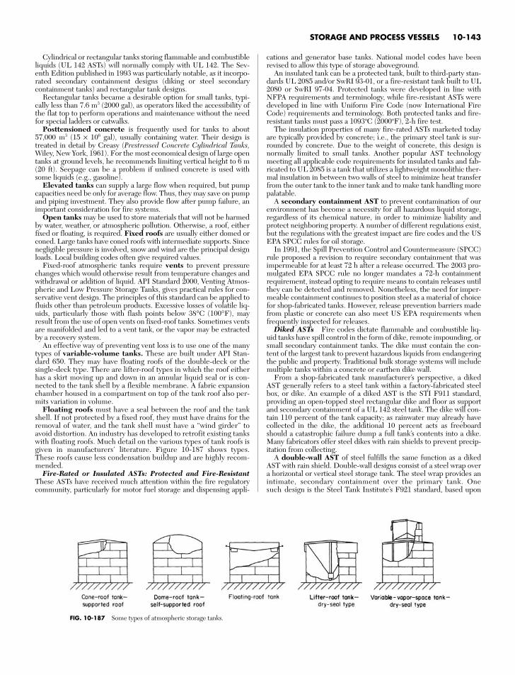
Cylindrical or rectangular tanks storing flammable and combustibleliquids (UL 142 ASTs) will normally comply with UL 142. The Sev-enth Edition published in 1993 was particularly notable, as it incorpo-rated secondary containment designs (diking or steel secondarycontainment tanks) and rectangular tank designs.
Rectangular tanks became a desirable option for small tanks, typi-cally less than 7.6 m3 (2000 gal), as operators liked the accessibility ofthe flat top to perform operations and maintenance without the needfor special ladders or catwalks.
Posttensioned concrete is frequently used for tanks to about57,000 m3 (15 × 106 gal), usually containing water. Their design istreated in detail by Creasy (Prestressed Concrete Cylindrical Tanks,Wiley, New York, 1961). For the most economical design of large opentanks at ground levels, he recommends limiting vertical height to 6 m(20 ft). Seepage can be a problem if unlined concrete is used withsome liquids (e.g., gasoline).
Elevated tanks can supply a large flow when required, but pumpcapacities need be only for average flow. Thus, they may save on pumpand piping investment. They also provide flow after pump failure, animportant consideration for fire systems.
Open tanks may be used to store materials that will not be harmedby water, weather, or atmospheric pollution. Otherwise, a roof, eitherfixed or floating, is required. Fixed roofs are usually either domed orconed. Large tanks have coned roofs with intermediate supports. Sincenegligible pressure is involved, snow and wind are the principal designloads. Local building codes often give required values.
Fixed-roof atmospheric tanks require vents to prevent pressurechanges which would otherwise result from temperature changes andwithdrawal or addition of liquid. API Standard 2000, Venting Atmos-pheric and Low Pressure Storage Tanks, gives practical rules for con-servative vent design. The principles of this standard can be applied tofluids other than petroleum products. Excessive losses of volatile liq-uids, particularly those with flash points below 38°C (100°F), mayresult from the use of open vents on fixed-roof tanks. Sometimes ventsare manifolded and led to a vent tank, or the vapor may be extractedby a recovery system.
An effective way of preventing vent loss is to use one of the manytypes of variable-volume tanks. These are built under API Stan-dard 650. They may have floating roofs of the double-deck or thesingle-deck type. There are lifter-roof types in which the roof eitherhas a skirt moving up and down in an annular liquid seal or is con-nected to the tank shell by a flexible membrane. A fabric expansionchamber housed in a compartment on top of the tank roof also per-mits variation in volume.
Floating roofs must have a seal between the roof and the tankshell. If not protected by a fixed roof, they must have drains for theremoval of water, and the tank shell must have a “wind girder” toavoid distortion. An industry has developed to retrofit existing tankswith floating roofs. Much detail on the various types of tank roofs isgiven in manufacturers’ literature. Figure 10-187 shows types.These roofs cause less condensation buildup and are highly recom-mended.
Fire-Rated or Insulated ASTs: Protected and Fire-ResistantThese ASTs have received much attention within the fire regulatorycommunity, particularly for motor fuel storage and dispensing appli-
cations and generator base tanks. National model codes have beenrevised to allow this type of storage aboveground.
An insulated tank can be a protected tank, built to third-party stan-dards UL 2085 and/or SwRI 93-01, or a fire-resistant tank built to UL2080 or SwRI 97-04. Protected tanks were developed in line withNFPA requirements and terminology, while fire-resistant ASTs weredeveloped in line with Uniform Fire Code (now International FireCode) requirements and terminology. Both protected tanks and fire-resistant tanks must pass a 1093oC (2000oF), 2-h fire test.
The insulation properties of many fire-rated ASTs marketed todayare typically provided by concrete; i.e., the primary steel tank is sur-rounded by concrete. Due to the weight of concrete, this design isnormally limited to small tanks. Another popular AST technologymeeting all applicable code requirements for insulated tanks and fab-ricated to UL 2085 is a tank that utilizes a lightweight monolithic ther-mal insulation in between two walls of steel to minimize heat transferfrom the outer tank to the inner tank and to make tank handling morepalatable.
A secondary containment AST to prevent contamination of ourenvironment has become a necessity for all hazardous liquid storage,regardless of its chemical nature, in order to minimize liability andprotect neighboring property. A number of different regulations exist,but the regulations with the greatest impact are fire codes and the USEPA SPCC rules for oil storage.
In 1991, the Spill Prevention Control and Countermeasure (SPCC)rule proposed a revision to require secondary containment that wasimpermeable for at least 72 h after a release occurred. The 2003 pro-mulgated EPA SPCC rule no longer mandates a 72-h containmentrequirement, instead opting to require means to contain releases untilthey can be detected and removed. Nonetheless, the need for imper-meable containment continues to position steel as a material of choicefor shop-fabricated tanks. However, release prevention barriers madefrom plastic or concrete can also meet US EPA requirements whenfrequently inspected for releases.
Diked ASTs Fire codes dictate flammable and combustible liq-uid tanks have spill control in the form of dike, remote impounding, orsmall secondary containment tanks. The dike must contain the con-tent of the largest tank to prevent hazardous liquids from endangeringthe public and property. Traditional bulk storage systems will includemultiple tanks within a concrete or earthen dike wall.
From a shop-fabricated tank manufacturer’s perspective, a dikedAST generally refers to a steel tank within a factory-fabricated steelbox, or dike. An example of a diked AST is the STI F911 standard,providing an open-topped steel rectangular dike and floor as supportand secondary containment of a UL 142 steel tank. The dike will con-tain 110 percent of the tank capacity; as rainwater may already havecollected in the dike, the additional 10 percent acts as freeboardshould a catastrophic failure dump a full tank’s contents into a dike.Many fabricators offer steel dikes with rain shields to prevent precip-itation from collecting.
A double-wall AST of steel fulfills the same function as a dikedAST with rain shield. Double-wall designs consist of a steel wrap overa horizontal or vertical steel storage tank. The steel wrap provides anintimate, secondary containment over the primary tank. Onesuch design is the Steel Tank Institute’s F921 standard, based upon
STORAGE AND PROCESS VESSELS 10-143
FIG. 10-187 Some types of atmospheric storage tanks.
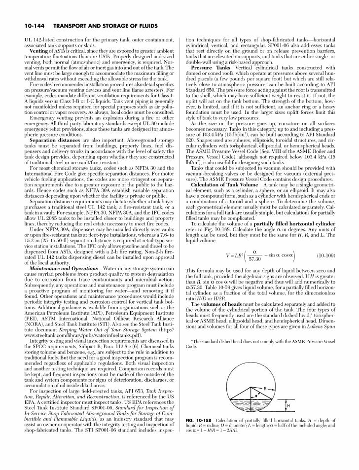
UL 142-listed construction for the primary tank, outer containment,associated tank supports or skids.
Venting of ASTs is critical, since they are exposed to greater ambienttemperature fluctuations than are USTs. Properly designed and sizedventing, both normal (atmospheric) and emergency, is required. Nor-mal vents permit the flow of air or inert gas into and out of the tank. Thevent line must be large enough to accommodate the maximum filling orwithdrawal rates without exceeding the allowable stress for the tank.
Fire codes’ recommended installation procedures also detail specificson pressure/vacuum venting devices and vent line flame arresters. Forexample, codes mandate different ventilation requirements for Class I-A liquids versus Class I-B or I-C liquids. Tank vent piping is generallynot manifolded unless required for special purposes such as air pollu-tion control or vapor recovery. As always, local codes must be consulted.
Emergency venting prevents an explosion during a fire or otheremergency. All third-party laboratory standards except UL 80 includeemergency relief provisions, since these tanks are designed for atmos-pheric pressure conditions.
Separation distances are also important. Aboveground storagetanks must be separated from buildings, property lines, fuel dis-pensers and delivery trucks in accordance with the level of safety thetank design provides, depending upon whether they are constructedof traditional steel or are vault/fire-resistant.
For most chemical storage tanks, codes such as NFPA 30 and theInternational Fire Code give specific separation distances. For motorvehicle fueling applications, the codes are more stringent on separa-tion requirements due to a greater exposure of the public to the haz-ards. Hence codes such as NFPA 30A establish variable separationdistances depending upon whether the facility is private or public.
Separation distance requirements may dictate whether a tank buyerpurchases a traditional steel UL 142 tank, a fire-resistant tank, or atank in a vault. For example, NFPA 30, NFPA 30A, and the IFC codesallow UL 2085 tanks to be installed closer to buildings and propertylines, thereby reducing the real estate necessary to meet fire codes.
Under NFPA 30A, dispensers may be installed directly over vaultsor upon fire-resistant tanks at fleet-type installations, whereas a 7.6- to15.2-m (25- to 50-ft) separation distance is required at retail-type ser-vice station installations. The IFC only allows gasoline and diesel to bedispensed from ASTs, designed with a 2-h fire rating. Non-2-h fire-rated UL 142 tanks dispensing diesel can be installed upon approvalof the local authority.
Maintenance and Operations Water in any storage system cancause myriad problems from product quality to system degradationdue to corrosion from trace contaminants and microbial action.Subsequently, any operations and maintenance program must includea proactive program of monitoring for water—and removing it iffound. Other operations and maintenance procedures would includeperiodic integrity testing and corrosion control for vertical tank bot-toms. Additional guidance is available from organizations such as theAmerican Petroleum Institute (API), Petroleum Equipment Institute(PEI), ASTM International, National Oilheat Research Alliance(NORA), and Steel Tank Institute (STI). Also see the Steel Tank Insti-tute document Keeping Water Out of Your Storage System (http://www.steeltank.com/library/pubs/waterinfueltanks.pdf).
Integrity testing and visual inspection requirements are discussed inthe SPCC requirements, Subpart B, Para. 112.8 c (6). Chemical tanksstoring toluene and benzene, e.g., are subject to the rule in addition totraditional fuels. But the need for a good inspection program is recom-mended regardless of applicable regulations. Both visual inspectionand another testing technique are required. Comparison records mustbe kept, and frequent inspections must be made of the outside of thetank and system components for signs of deterioration, discharges, oraccumulation of oil inside diked areas.
For inspection of large field-erected tanks, API 653, Tank Inspec-tion, Repair, Alteration, and Reconstruction, is referenced by the USEPA. A certified inspector must inspect tanks. US EPA references theSteel Tank Institute Standard SP001-06, Standard for Inspection ofIn-Service Shop Fabricated Aboveground Tanks for Storage of Com-bustible and Flammable Liquids, as an industry standard that mayassist an owner or operator with the integrity testing and inspection ofshop-fabricated tanks. The STI SP001-06 standard includes inspec-
tion techniques for all types of shop-fabricated tanks—horizontalcylindrical, vertical, and rectangular. SP001-06 also addresses tanksthat rest directly on the ground or on release prevention barriers,tanks that are elevated on supports, and tanks that are either single- ordouble-wall using a risk-based approach.
Pressure Tanks Vertical cylindrical tanks constructed withdomed or coned roofs, which operate at pressures above several hun-dred pascals (a few pounds per square foot) but which are still rela-tively close to atmospheric pressure, can be built according to APIStandard 650. The pressure force acting against the roof is transmittedto the shell, which may have sufficient weight to resist it. If not, theuplift will act on the tank bottom. The strength of the bottom, how-ever, is limited, and if it is not sufficient, an anchor ring or a heavyfoundation must be used. In the larger sizes uplift forces limit thisstyle of tank to very low pressures.
As the size or the pressure goes up, curvature on all surfacesbecomes necessary. Tanks in this category, up to and including a pres-sure of 103.4 kPa (15 lbf/in2), can be built according to API Standard620. Shapes used are spheres, ellipsoids, toroidal structures, and cir-cular cylinders with torispherical, ellipsoidal, or hemispherical heads.The ASME Pressure Vessel Code (Sec. VIII of the ASME Boiler andPressure Vessel Code), although not required below 103.4 kPa (15lbf/in2), is also useful for designing such tanks.
Tanks that could be subjected to vacuum should be provided withvacuum-breaking valves or be designed for vacuum (external pres-sure). The ASME Pressure Vessel Code contains design procedures.
Calculation of Tank Volume A tank may be a single geometri-cal element, such as a cylinder, a sphere, or an ellipsoid. It may alsohave a compound form, such as a cylinder with hemispherical ends ora combination of a toroid and a sphere. To determine the volume,each geometrical element usually must be calculated separately. Cal-culations for a full tank are usually simple, but calculations for partiallyfilled tanks may be complicated.
To calculate the volume of a partially filled horizontal cylinderrefer to Fig. 10-188. Calculate the angle α in degrees. Any units oflength can be used, but they must be the same for H, R, and L. Theliquid volume
V = LR2 − sin α cos α (10-109)
This formula may be used for any depth of liquid between zero andthe full tank, provided the algebraic signs are observed. If H is greaterthan R, sin α cos α will be negative and thus will add numerically toα/57.30. Table 10-59 gives liquid volume, for a partially filled horizon-tal cylinder, as a fraction of the total volume, for the dimensionlessratio H/D or H/2R.
The volumes of heads must be calculated separately and added tothe volume of the cylindrical portion of the tank. The four types ofheads most frequently used are the standard dished head,* torispher-ical or ASME head, ellipsoidal head, and hemispherical head. Dimen-sions and volumes for all four of these types are given in Lukens Spun
α57.30
10-144 TRANSPORT AND STORAGE OF FLUIDS
FIG. 10-188 Calculation of partially filled horizontal tanks. H = depth of liquid; R = radius; D = diameter; L = length; α = half of the included angle; andcos α = 1 − H/R = 1 − 2H/D.
*The standard dished head does not comply with the ASME Pressure VesselCode.
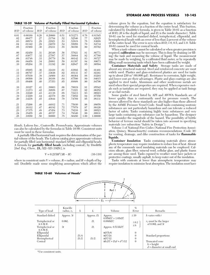
Heads, Lukens Inc., Coatesville, Pennsylvania. Approximate volumescan also be calculated by the formulas in Table 10-60. Consistent unitsmust be used in these formulas.
A partially filled horizontal tank requires the determination of the par-tial volume of the heads. The Lukens catalog gives approximate volumesfor partially filled (axis horizontal) standard ASME and ellipsoidal heads.A formula for partially filled heads (excluding conical), by Doolittle[Ind. Eng. Chem., 21, 322–323 (1928)], is
V = 0.215H2(3R − H) (10-110)
where in consistent units V = volume, R = radius, and H = depth of liq-uid. Doolittle made some simplifying assumptions which affect the
volume given by the equation, but the equation is satisfactory fordetermining the volume as a fraction of the entire head. This fraction,calculated by Doolittle’s formula, is given in Table 10-61 as a functionof H/Di (H is the depth of liquid, and Di is the inside diameter). Table10-61 can be used for standard dished, torispherical, ellipsoidal, andhemispherical heads with an error of less than 2 percent of the volumeof the entire head. The error is zero when H/Di = 0, 0.5, and 1.0. Table10-61 cannot be used for conical heads.
When a tank volume cannot be calculated or when greater precision isrequired, calibration may be necessary. This is done by draining (or fill-ing) the tank and measuring the volume of liquid. The measurementmay be made by weighing, by a calibrated fluid meter, or by repeatedlyfilling small measuring tanks which have been calibrated by weight.
Container Materials and Safety Storage tanks are made ofalmost any structural material. Steel and reinforced concrete are mostwidely used. Plastics and glass-reinforced plastics are used for tanksup to about 230 m3 (60,000 gal). Resistance to corrosion, light weight,and lower cost are their advantages. Plastic and glass coatings are alsoapplied to steel tanks. Aluminum and other nonferrous metals areused when their special properties are required. When expensive met-als such as tantalum are required, they may be applied as tank liningsor as clad metals.
Some grades of steel listed by API and AWWA Standards are oflower quality than is customarily used for pressure vessels. Thestresses allowed by these standards are also higher than those allowedby the ASME Pressure Vessel Code. Small tanks containing nontoxicsubstances are not particularly hazardous and can tolerate a reducedfactor of safety. Tanks containing highly toxic substances and verylarge tanks containing any substance can be hazardous. The designermust consider the magnitude of the hazard. The possibility of brittlebehavior of ferrous metal should be taken into account in specifyingmaterials (see subsection “Safety in Design”).
Volume 1 of National Fire Codes (National Fire Protection Associ-ation, Quincy, Massachusetts) contains recommendations (Code 30)for venting, drainage, and dike construction of tanks for flammableliquids.
Container Insulation Tanks containing materials above atmos-pheric temperature may require insulation to reduce loss of heat. Almostany of the commonly used insulating materials can be employed. Cal-cium silicate, glass fiber, mineral wool, cellular glass, and plastic foamsare among those used. Tanks exposed to weather must have jackets orprotective coatings, usually asphalt, to keep water out of the insulation.
Tanks with contents at lower than atmospheric temperature mayrequire insulation to minimize heat absorption. The insulation must have
STORAGE AND PROCESS VESSELS 10-145
TABLE 10-60 Volumes of Heads*
Knuckle %Type of head radius, rk h L Volume Error Remarks
Standard dished Approx. 3t Approx. Di Approx. 10 h varies with t0.050Di
3 + 1.65tDi2
Torispherical or 0.06L Di 0.0809Di3
0.1 rk must be the largerA.S.M.E. of 0.06L and 3t
Torispherical or 3t Di Approx. 0.513hDi2 8
A.S.M.E.Ellipsoidal πDi
2h/6 0Ellipsoidal Di /4 πDi
3/24 0 Standard proportionsHemispherical Di /2 Di /2 πDi
3/12 0Conical πh(Di
2 + Did + d 2)/12 0 Truncated coneh = heightd = diameter at small end
*Use consistent units.
TABLE 10-59 Volume of Partially Filled Horizontal Cylinders
Fraction Fraction Fraction FractionH/D of volume H/D of volume H/D of volume H/D of volume
0.01 0.00169 0.26 0.20660 0.51 0.51273 0.76 0.81545.02 .00477 .27 .21784 .52 .52546 .77 .82625.03 .00874 .28 .22921 .53 .53818 .78 .83688.04 .01342 .29 .24070 .54 .55088 .79 .84734.05 .01869 .30 .25231 .55 .56356 .80 .85762
.06 .02450 .31 .26348 .56 .57621 .81 .86771
.07 .03077 .32 .27587 .57 .58884 .82 .87760
.08 .03748 .33 .28779 .58 .60142 .83 .88727
.09 .04458 .34 .29981 .59 .61397 .84 .89673
.10 .05204 .35 .31192 .60 .62647 .85 .90594
.11 .05985 .36 .32410 .61 .63892 .86 .91491
.12 .06797 .37 .33636 .62 .65131 .87 .92361
.13 .07639 .38 .34869 .63 .66364 .88 .93203
.14 .08509 .39 .36108 .64 .67590 .89 .94015
.15 .09406 .40 .37353 .65 .68808 .90 .94796
.16 .10327 .41 .38603 .66 .70019 .91 .95542
.17 .11273 .42 .39858 .67 .71221 .92 .96252
.18 .12240 .43 .41116 .68 .72413 .93 .96923
.19 .13229 .44 .42379 .69 .73652 .94 .97550
.20 .14238 .45 .43644 .70 .74769 .95 .98131
.21 .15266 .46 .44912 .71 .75930 .96 .98658
.22 .16312 .47 .46182 .72 .77079 .97 .99126
.23 .17375 .48 .47454 .73 .78216 .98 .99523
.24 .18455 .49 .48727 .74 .79340 .99 .99831
.25 .19550 .50 .50000 .75 .80450 1.00 1.00000
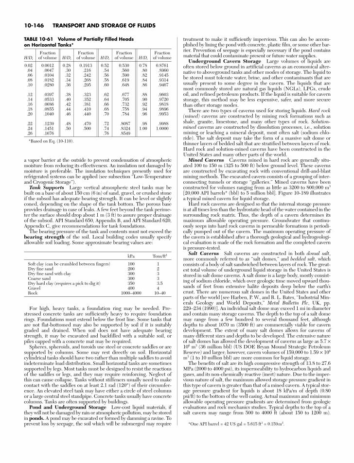
a vapor barrier at the outside to prevent condensation of atmosphericmoisture from reducing its effectiveness. An insulation not damaged bymoisture is preferable. The insulation techniques presently used forrefrigerated systems can be applied (see subsection “Low-Temperatureand Cryogenic Storage”).
Tank Supports Large vertical atmospheric steel tanks may bebuilt on a base of about 150 cm (6 in) of sand, gravel, or crushed stoneif the subsoil has adequate bearing strength. It can be level or slightlyconed, depending on the shape of the tank bottom. The porous baseprovides drainage in case of leaks. A few feet beyond the tank perime-ter the surface should drop about 1 m (3 ft) to assure proper drainageof the subsoil. API Standard 650, Appendix B, and API Standard 620,Appendix C, give recommendations for tank foundations.
The bearing pressure of the tank and contents must not exceed thebearing strength of the soil. Local building codes usually specifyallowable soil loading. Some approximate bearing values are:
kPa Tons/ft2
Soft clay (can be crumbled between fingers) 100 1Dry fine sand 200 2Dry fine sand with clay 300 3Coarse sand 300 3Dry hard clay (requires a pick to dig it) 350 3.5Gravel 400 4Rock 1000–4000 10–40
For high, heavy tanks, a foundation ring may be needed. Pre-stressed concrete tanks are sufficiently heavy to require foundationrings. Foundations must extend below the frost line. Some tanks thatare not flat-bottomed may also be supported by soil if it is suitablygraded and drained. When soil does not have adequate bearingstrength, it may be excavated and backfilled with a suitable soil, orpiles capped with a concrete mat may be required.
Spheres, spheroids, and toroids use steel or concrete saddles or aresupported by columns. Some may rest directly on soil. Horizontalcylindrical tanks should have two rather than multiple saddles to avoidindeterminate load distribution. Small horizontal tanks are sometimessupported by legs. Most tanks must be designed to resist the reactionsof the saddles or legs, and they may require reinforcing. Neglect ofthis can cause collapse. Tanks without stiffeners usually need to makecontact with the saddles on at least 2.1 rad (120°) of their circumfer-ence. An elevated steel tank may have either a circle of steel columnsor a large central steel standpipe. Concrete tanks usually have concretecolumns. Tanks are often supported by buildings.
Pond and Underground Storage Low-cost liquid materials, ifthey will not be damaged by rain or atmospheric pollution, may be storedin ponds. A pond may be excavated or formed by damming a ravine. Toprevent loss by seepage, the soil which will be submerged may require
treatment to make it sufficiently impervious. This can also be accom-plished by lining the pond with concrete, plastic film, or some other bar-rier. Prevention of seepage is especially necessary if the pond containsmaterial that could contaminate present or future water supplies.
Underground Cavern Storage Large volumes of liquids areoften stored below ground in artificial caverns as an economical alter-native to aboveground tanks and other modes of storage. The liquid tobe stored must tolerate water, brine, and other contaminants that areusually present to some degree in the cavern. The liquids that aremost commonly stored are natural gas liquids (NGLs), LPGs, crudeoil, and refined petroleum products. If the liquid is suitable for cavernstorage, this method may be less expensive, safer, and more securethan other storage modes.
There are two types of caverns used for storing liquids. Hard rock(mined) caverns are constructed by mining rock formations such asshale, granite, limestone, and many other types of rock. Solution-mined caverns are constructed by dissolution processes, i.e., solutionmining or leaching a mineral deposit, most often salt (sodium chlo-ride). The salt deposit may take the form of a massive salt dome orthinner layers of bedded salt that are stratified between layers of rock.Hard rock and solution-mined caverns have been constructed in theUnited States and many other parts of the world.
Mined Caverns Caverns mined in hard rock are generally situ-ated 100 to 150 m (325 to 500 ft) below ground level. These cavernsare constructed by excavating rock with conventional drill-and-blastmining methods. The excavated cavern consists of a grouping of inter-connecting tunnels or storage “galleries.” Mined caverns have beenconstructed for volumes ranging from as little as 3200 to 800,000 m3
[20,000 API barrels* (bbl) to 5 million bbl]. Figure 10-189 illustratesa typical mined cavern for liquid storage.
Hard rock caverns are designed so that the internal storage pressureis at all times less than the hydrostatic head of the water contained in thesurrounding rock matrix. Thus, the depth of a cavern determines itsmaximum allowable operating pressure. Groundwater that continu-ously seeps into hard rock caverns in permeable formations is periodi-cally pumped out of the cavern. The maximum operating pressure ofthe cavern is established after a thorough geological and hydrogeologi-cal evaluation is made of the rock formation and the completed cavernis pressure-tested.
Salt Caverns Salt caverns are constructed in both domal salt,more commonly referred to as “salt domes,” and bedded salt, whichconsists of a body of salt sandwiched between layers of rock. The great-est total volume of underground liquid storage in the United States isstored in salt dome caverns. A salt dome is a large body, mostly consist-ing of sodium chloride, which over geologic time moved upward thou-sands of feet from extensive halite deposits deep below the earth’scrust. There are numerous salt domes in the United States and otherparts of the world [see Harben, P. W., and R. L. Bates, “Industrial Min-erals Geology and World Deposits,” Metal Bulletin Plc, UK, pp.229–234 (1990)]. An individual salt dome may exceed 1 mi in diameterand contain many storage caverns. The depth to the top of a salt domemay range from a few hundred to several thousand feet, althoughdepths to about 1070 m (3500 ft) are commercially viable for caverndevelopment. The extent of many salt domes allows for caverns ofmany different sizes and depths to be developed. The extensive natureof salt domes has allowed the development of caverns as large as 5.7 ×10⁶ m3 (36 million bbl) (US DOE Bryan Mound Strategic PetroleumReserve) and larger; however, cavern volumes of 159,000 to 1.59 × 10⁶
m3 (1 to 10 million bbl) are more common for liquid storage.The benefits of salt are its high compressive strength of 13.8 to 27.6
MPa (2000 to 4000 psi), its impermeability to hydrocarbon liquids andgases, and its non-chemically reactive (inert) nature. Due to the imper-vious nature of salt, the maximum allowed storage pressure gradient inthis type of cavern is greater than that of a mined cavern. A typical stor-age pressure gradient for liquids is about 18 kPa/m of depth (0.80psi/ft) to the bottom of the well casing. Actual maximum and minimumallowable operating pressure gradients are determined from geologicevaluations and rock mechanics studies. Typical depths to the top of asalt cavern may range from 500 to 4000 ft (about 150 to 1200 m).
10-146 TRANSPORT AND STORAGE OF FLUIDS
*One API barrel = 42 US gal = 5.615 ft3 = 0.159m2.
TABLE 10-61 Volume of Partially Filled Heads on Horizontal Tanks*
Fraction Fraction Fraction FractionH/Di of volume H/Di of volume H/Di of volume H/Di of volume
0.02 0.0012 0.28 0.1913 0.52 0.530 0.78 0.8761.04 .0047 .30 .216 .54 .560 .80 .8960.06 .0104 .32 .242 .56 .590 .82 .9145.08 .0182 .34 .268 .58 .619 .84 .9314.10 .0280 .36 .295 .60 .648 .86 .9467
.12 .0397 .38 .323 .62 .677 .88 .9603
.14 .0533 .40 .352 .64 .705 .90 .9720
.16 .0686 .42 .381 .66 .732 .92 .9818
.18 .0855 .44 .410 .68 .758 .94 .9896
.20 .1040 .46 .440 .70 .784 .96 .9953
.22 .1239 .48 .470 .72 .8087 .98 .9988
.24 .1451 .50 .500 .74 .8324 1.00 1.0000
.26 .1676 .76 .8549
*Based on Eq. (10-110).
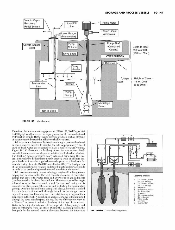
FIG. 10–190 Cavern leaching process.
FIG. 10-189 Mined cavern.
Therefore, the maximum storage pressure (2760 to 32,060 kPag, or 400to 3200 psig) usually exceeds the vapor pressure of all commonly storedhydrocarbon liquids. Higher-vapor-pressure products such as ethyleneor ethane cannot be stored in relatively shallow caverns.
Salt caverns are developed by solution mining, a process (leaching)in which water is injected to dissolve the salt. Approximately 7 to 10units of fresh water are required to leach 1 unit of cavern volume.Figure 10-190 illustrates the leaching process for two caverns. Mod-ern salt dome caverns are shaped as relatively tall, slender cylinders.The leaching process produces nearly saturated brine from the cav-ern. Brine may be disposed into nearby disposal wells or offshore dis-posal fields, or it may be supplied to nearby plants as a feedstock formanufacturing of caustic (NaOH) and chlorine (Cl2). The final portionof the produced brine is retained and stored in artificial surface pondsor tanks to be used to displace the stored liquid from the cavern.
Salt caverns are usually developed using a single well, although someemploy two or more wells. The well consists of a series of concentriccasings that protect the water table and layers of rock and sediments(overburden) that lie above the salt dome. The innermost well casing isreferred to as the last cemented or well “production” casing and iscemented in place, sealing the cavern and protecting the surroundinggeology. Once the last cemented casing is in place, a borehole is drilledfrom the bottom of the well, through the salt to the design caverndepth. For single-well leaching, two concentric tubing strings are thensuspended in the well. A liquid, such as diesel, or a gas is then injectedthrough the outer annular space and into the top of the cavern to act asa “blanket” to prevent undesired leaching of the top of the cavern.Water is then injected into one of the suspended tubing strings, andbrine is withdrawn from the other. During the leaching process, theflow path for the injected water is alternated between the innermost
STORAGE AND PROCESS VESSELS 10-147
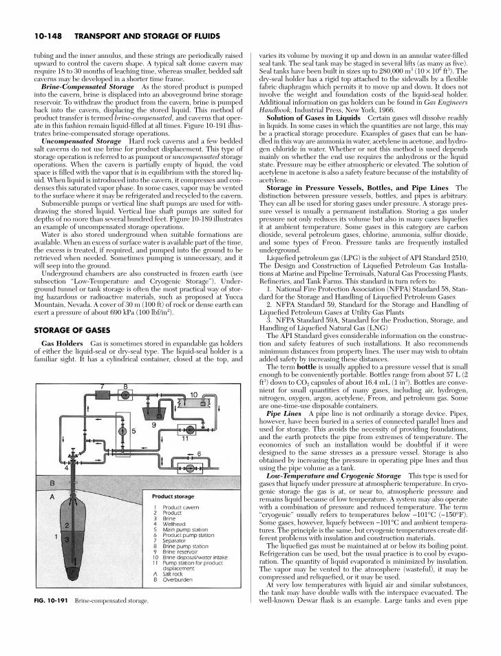
tubing and the inner annulus, and these strings are periodically raisedupward to control the cavern shape. A typical salt dome cavern mayrequire 18 to 30 months of leaching time, whereas smaller, bedded saltcaverns may be developed in a shorter time frame.
Brine-Compensated Storage As the stored product is pumpedinto the cavern, brine is displaced into an aboveground brine storagereservoir. To withdraw the product from the cavern, brine is pumpedback into the cavern, displacing the stored liquid. This method ofproduct transfer is termed brine-compensated, and caverns that oper-ate in this fashion remain liquid-filled at all times. Figure 10-191 illus-trates brine-compensated storage operations.
Uncompensated Storage Hard rock caverns and a few beddedsalt caverns do not use brine for product displacement. This type ofstorage operation is referred to as pumpout or uncompensated storageoperations. When the cavern is partially empty of liquid, the voidspace is filled with the vapor that is in equilibrium with the stored liq-uid. When liquid is introduced into the cavern, it compresses and con-denses this saturated vapor phase. In some cases, vapor may be ventedto the surface where it may be refrigerated and recycled to the cavern.
Submersible pumps or vertical line shaft pumps are used for with-drawing the stored liquid. Vertical line shaft pumps are suited fordepths of no more than several hundred feet. Figure 10-189 illustratesan example of uncompensated storage operations.
Water is also stored underground when suitable formations areavailable. When an excess of surface water is available part of the time,the excess is treated, if required, and pumped into the ground to beretrieved when needed. Sometimes pumping is unnecessary, and itwill seep into the ground.
Underground chambers are also constructed in frozen earth (seesubsection “Low-Temperature and Cryogenic Storage”). Under-ground tunnel or tank storage is often the most practical way of stor-ing hazardous or radioactive materials, such as proposed at YuccaMountain, Nevada. A cover of 30 m (100 ft) of rock or dense earth canexert a pressure of about 690 kPa (100 lbf/in2).
STORAGE OF GASES
Gas Holders Gas is sometimes stored in expandable gas holdersof either the liquid-seal or dry-seal type. The liquid-seal holder is afamiliar sight. It has a cylindrical container, closed at the top, and
varies its volume by moving it up and down in an annular water-filledseal tank. The seal tank may be staged in several lifts (as many as five).Seal tanks have been built in sizes up to 280,000 m3 (10 × 106 ft3). Thedry-seal holder has a rigid top attached to the sidewalls by a flexiblefabric diaphragm which permits it to move up and down. It does notinvolve the weight and foundation costs of the liquid-seal holder.Additional information on gas holders can be found in Gas EngineersHandbook, Industrial Press, New York, 1966.
Solution of Gases in Liquids Certain gases will dissolve readilyin liquids. In some cases in which the quantities are not large, this maybe a practical storage procedure. Examples of gases that can be han-dled in this way are ammonia in water, acetylene in acetone, and hydro-gen chloride in water. Whether or not this method is used dependsmainly on whether the end use requires the anhydrous or the liquidstate. Pressure may be either atmospheric or elevated. The solution ofacetylene in acetone is also a safety feature because of the instability ofacetylene.
Storage in Pressure Vessels, Bottles, and Pipe Lines Thedistinction between pressure vessels, bottles, and pipes is arbitrary.They can all be used for storing gases under pressure. A storage pres-sure vessel is usually a permanent installation. Storing a gas underpressure not only reduces its volume but also in many cases liquefiesit at ambient temperature. Some gases in this category are carbondioxide, several petroleum gases, chlorine, ammonia, sulfur dioxide,and some types of Freon. Pressure tanks are frequently installedunderground.
Liquefied petroleum gas (LPG) is the subject of API Standard 2510,The Design and Construction of Liquefied Petroleum Gas Installa-tions at Marine and Pipeline Terminals, Natural Gas Processing Plants,Refineries, and Tank Farms. This standard in turn refers to:
1. National Fire Protection Association (NFPA) Standard 58, Stan-dard for the Storage and Handling of Liquefied Petroleum Gases
2. NFPA Standard 59, Standard for the Storage and Handling ofLiquefied Petroleum Gases at Utility Gas Plants
3. NFPA Standard 59A, Standard for the Production, Storage, andHandling of Liquefied Natural Gas (LNG)
The API Standard gives considerable information on the construc-tion and safety features of such installations. It also recommendsminimum distances from property lines. The user may wish to obtainadded safety by increasing these distances.
The term bottle is usually applied to a pressure vessel that is smallenough to be conveniently portable. Bottles range from about 57 L (2ft3) down to CO2 capsules of about 16.4 mL (1 in3). Bottles are conve-nient for small quantities of many gases, including air, hydrogen,nitrogen, oxygen, argon, acetylene, Freon, and petroleum gas. Someare one-time-use disposable containers.
Pipe Lines A pipe line is not ordinarily a storage device. Pipes,however, have been buried in a series of connected parallel lines andused for storage. This avoids the necessity of providing foundations,and the earth protects the pipe from extremes of temperature. Theeconomics of such an installation would be doubtful if it weredesigned to the same stresses as a pressure vessel. Storage is alsoobtained by increasing the pressure in operating pipe lines and thususing the pipe volume as a tank.
Low-Temperature and Cryogenic Storage This type is used forgases that liquefy under pressure at atmospheric temperature. In cryo-genic storage the gas is at, or near to, atmospheric pressure andremains liquid because of low temperature. A system may also operatewith a combination of pressure and reduced temperature. The term“cryogenic” usually refers to temperatures below −101°C (−150°F).Some gases, however, liquefy between −101°C and ambient tempera-tures. The principle is the same, but cryogenic temperatures create dif-ferent problems with insulation and construction materials.
The liquefied gas must be maintained at or below its boiling point.Refrigeration can be used, but the usual practice is to cool by evapo-ration. The quantity of liquid evaporated is minimized by insulation.The vapor may be vented to the atmosphere (wasteful), it may becompressed and reliquefied, or it may be used.
At very low temperatures with liquid air and similar substances,the tank may have double walls with the interspace evacuated. Thewell-known Dewar flask is an example. Large tanks and even pipe
10-148 TRANSPORT AND STORAGE OF FLUIDS
FIG. 10-191 Brine-compensated storage.
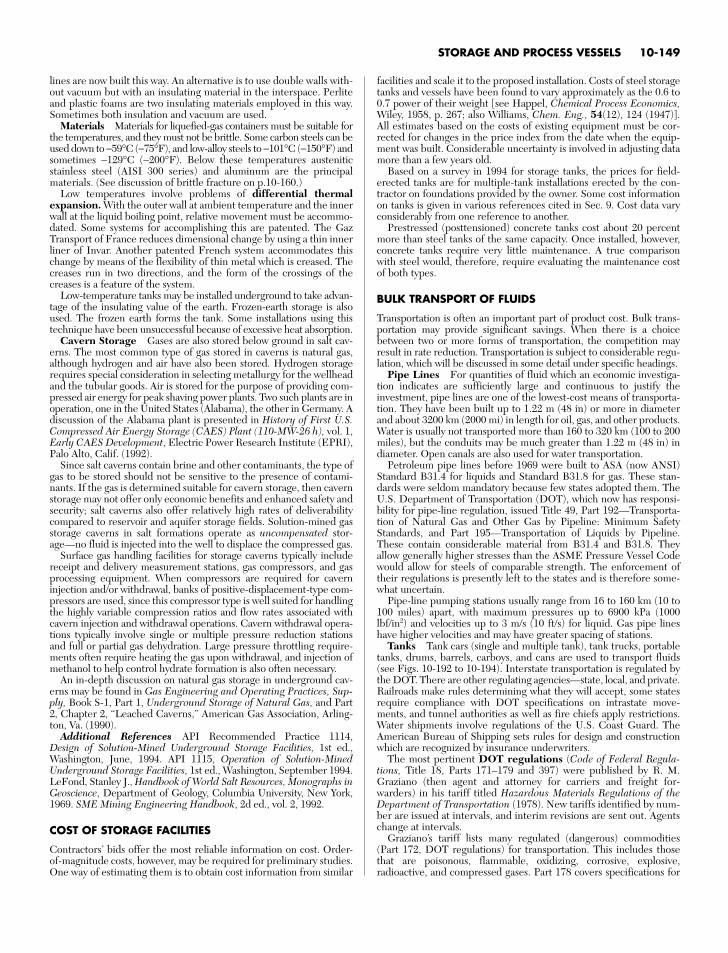
lines are now built this way. An alternative is to use double walls with-out vacuum but with an insulating material in the interspace. Perliteand plastic foams are two insulating materials employed in this way.Sometimes both insulation and vacuum are used.
Materials Materials for liquefied-gas containers must be suitable forthe temperatures, and they must not be brittle. Some carbon steels can beused down to −59°C (−75°F), and low-alloy steels to −101°C (−150°F) andsometimes −129°C (−200°F). Below these temperatures austeniticstainless steel (AISI 300 series) and aluminum are the principalmaterials. (See discussion of brittle fracture on p.10-160.)
Low temperatures involve problems of differential thermalexpansion. With the outer wall at ambient temperature and the innerwall at the liquid boiling point, relative movement must be accommo-dated. Some systems for accomplishing this are patented. The GazTransport of France reduces dimensional change by using a thin innerliner of Invar. Another patented French system accommodates thischange by means of the flexibility of thin metal which is creased. Thecreases run in two directions, and the form of the crossings of thecreases is a feature of the system.
Low-temperature tanks may be installed underground to take advan-tage of the insulating value of the earth. Frozen-earth storage is alsoused. The frozen earth forms the tank. Some installations using thistechnique have been unsuccessful because of excessive heat absorption.
Cavern Storage Gases are also stored below ground in salt cav-erns. The most common type of gas stored in caverns is natural gas,although hydrogen and air have also been stored. Hydrogen storagerequires special consideration in selecting metallurgy for the wellheadand the tubular goods. Air is stored for the purpose of providing com-pressed air energy for peak shaving power plants. Two such plants are inoperation, one in the United States (Alabama), the other in Germany. Adiscussion of the Alabama plant is presented in History of First U.S.Compressed Air Energy Storage (CAES) Plant (110-MW-26 h), vol. 1,Early CAES Development, Electric Power Research Institute (EPRI),Palo Alto, Calif. (1992).
Since salt caverns contain brine and other contaminants, the type ofgas to be stored should not be sensitive to the presence of contami-nants. If the gas is determined suitable for cavern storage, then cavernstorage may not offer only economic benefits and enhanced safety andsecurity; salt caverns also offer relatively high rates of deliverabilitycompared to reservoir and aquifer storage fields. Solution-mined gasstorage caverns in salt formations operate as uncompensated stor-age—no fluid is injected into the well to displace the compressed gas.
Surface gas handling facilities for storage caverns typically includereceipt and delivery measurement stations, gas compressors, and gasprocessing equipment. When compressors are required for caverninjection and/or withdrawal, banks of positive-displacement-type com-pressors are used, since this compressor type is well suited for handlingthe highly variable compression ratios and flow rates associated withcavern injection and withdrawal operations. Cavern withdrawal opera-tions typically involve single or multiple pressure reduction stationsand full or partial gas dehydration. Large pressure throttling require-ments often require heating the gas upon withdrawal, and injection ofmethanol to help control hydrate formation is also often necessary.
An in-depth discussion on natural gas storage in underground cav-erns may be found in Gas Engineering and Operating Practices, Sup-ply, Book S-1, Part 1, Underground Storage of Natural Gas, and Part2, Chapter 2, “Leached Caverns,” American Gas Association, Arling-ton, Va. (1990).
Additional References API Recommended Practice 1114,Design of Solution-Mined Underground Storage Facilities, 1st ed.,Washington, June, 1994. API 1115, Operation of Solution-MinedUnderground Storage Facilities, 1st ed., Washington, September 1994.LeFond, Stanley J., Handbook of World Salt Resources, Monographs inGeoscience, Department of Geology, Columbia University, New York,1969. SME Mining Engineering Handbook, 2d ed., vol. 2, 1992.
COST OF STORAGE FACILITIES
Contractors’ bids offer the most reliable information on cost. Order-of-magnitude costs, however, may be required for preliminary studies.One way of estimating them is to obtain cost information from similar
facilities and scale it to the proposed installation. Costs of steel storagetanks and vessels have been found to vary approximately as the 0.6 to0.7 power of their weight [see Happel, Chemical Process Economics,Wiley, 1958, p. 267; also Williams, Chem. Eng., 54(12), 124 (1947)].All estimates based on the costs of existing equipment must be cor-rected for changes in the price index from the date when the equip-ment was built. Considerable uncertainty is involved in adjusting datamore than a few years old.
Based on a survey in 1994 for storage tanks, the prices for field-erected tanks are for multiple-tank installations erected by the con-tractor on foundations provided by the owner. Some cost informationon tanks is given in various references cited in Sec. 9. Cost data varyconsiderably from one reference to another.
Prestressed (posttensioned) concrete tanks cost about 20 percentmore than steel tanks of the same capacity. Once installed, however,concrete tanks require very little maintenance. A true comparisonwith steel would, therefore, require evaluating the maintenance costof both types.
BULK TRANSPORT OF FLUIDS
Transportation is often an important part of product cost. Bulk trans-portation may provide significant savings. When there is a choicebetween two or more forms of transportation, the competition mayresult in rate reduction. Transportation is subject to considerable regu-lation, which will be discussed in some detail under specific headings.
Pipe Lines For quantities of fluid which an economic investiga-tion indicates are sufficiently large and continuous to justify theinvestment, pipe lines are one of the lowest-cost means of transporta-tion. They have been built up to 1.22 m (48 in) or more in diameterand about 3200 km (2000 mi) in length for oil, gas, and other products.Water is usually not transported more than 160 to 320 km (100 to 200miles), but the conduits may be much greater than 1.22 m (48 in) indiameter. Open canals are also used for water transportation.
Petroleum pipe lines before 1969 were built to ASA (now ANSI)Standard B31.4 for liquids and Standard B31.8 for gas. These stan-dards were seldom mandatory because few states adopted them. TheU.S. Department of Transportation (DOT), which now has responsi-bility for pipe-line regulation, issued Title 49, Part 192—Transporta-tion of Natural Gas and Other Gas by Pipeline: Minimum SafetyStandards, and Part 195—Transportation of Liquids by Pipeline.These contain considerable material from B31.4 and B31.8. Theyallow generally higher stresses than the ASME Pressure Vessel Codewould allow for steels of comparable strength. The enforcement oftheir regulations is presently left to the states and is therefore some-what uncertain.
Pipe-line pumping stations usually range from 16 to 160 km (10 to100 miles) apart, with maximum pressures up to 6900 kPa (1000lbf/in2) and velocities up to 3 m/s (10 ft/s) for liquid. Gas pipe lineshave higher velocities and may have greater spacing of stations.
Tanks Tank cars (single and multiple tank), tank trucks, portabletanks, drums, barrels, carboys, and cans are used to transport fluids(see Figs. 10-192 to 10-194). Interstate transportation is regulated bythe DOT. There are other regulating agencies—state, local, and private.Railroads make rules determining what they will accept, some statesrequire compliance with DOT specifications on intrastate move-ments, and tunnel authorities as well as fire chiefs apply restrictions.Water shipments involve regulations of the U.S. Coast Guard. TheAmerican Bureau of Shipping sets rules for design and constructionwhich are recognized by insurance underwriters.
The most pertinent DOT regulations (Code of Federal Regula-tions, Title 18, Parts 171–179 and 397) were published by R. M.Graziano (then agent and attorney for carriers and freight for-warders) in his tariff titled Hazardous Materials Regulations of theDepartment of Transportation (1978). New tariffs identified by num-ber are issued at intervals, and interim revisions are sent out. Agentschange at intervals.
Graziano’s tariff lists many regulated (dangerous) commodities(Part 172, DOT regulations) for transportation. This includes thosethat are poisonous, flammable, oxidizing, corrosive, explosive,radioactive, and compressed gases. Part 178 covers specifications for
STORAGE AND PROCESS VESSELS 10-149
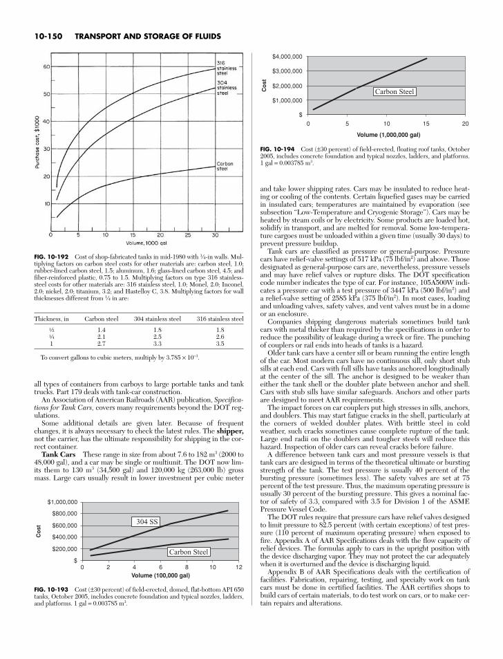
all types of containers from carboys to large portable tanks and tanktrucks. Part 179 deals with tank-car construction.
An Association of American Railroads (AAR) publication, Specifica-tions for Tank Cars, covers many requirements beyond the DOT reg-ulations.
Some additional details are given later. Because of frequentchanges, it is always necessary to check the latest rules. The shipper,not the carrier, has the ultimate responsibility for shipping in the cor-rect container.
Tank Cars These range in size from about 7.6 to 182 m3 (2000 to48,000 gal), and a car may be single or multiunit. The DOT now lim-its them to 130 m3 (34,500 gal) and 120,000 kg (263,000 lb) grossmass. Large cars usually result in lower investment per cubic meter
and take lower shipping rates. Cars may be insulated to reduce heat-ing or cooling of the contents. Certain liquefied gases may be carriedin insulated cars; temperatures are maintained by evaporation (seesubsection “Low-Temperature and Cryogenic Storage”). Cars may beheated by steam coils or by electricity. Some products are loaded hot,solidify in transport, and are melted for removal. Some low-tempera-ture cargoes must be unloaded within a given time (usually 30 days) toprevent pressure buildup.
Tank cars are classified as pressure or general-purpose. Pressurecars have relief-valve settings of 517 kPa (75 lbf/in2) and above. Thosedesignated as general-purpose cars are, nevertheless, pressure vesselsand may have relief valves or rupture disks. The DOT specificationcode number indicates the type of car. For instance, 105A500W indi-cates a pressure car with a test pressure of 3447 kPa (500 lbf/in2) anda relief-valve setting of 2585 kPa (375 lbf/in2). In most cases, loadingand unloading valves, safety valves, and vent valves must be in a domeor an enclosure.
Companies shipping dangerous materials sometimes build tankcars with metal thicker than required by the specifications in order toreduce the possibility of leakage during a wreck or fire. The punchingof couplers or rail ends into heads of tanks is a hazard.
Older tank cars have a center sill or beam running the entire lengthof the car. Most modern cars have no continuous sill, only short stubsills at each end. Cars with full sills have tanks anchored longitudinallyat the center of the sill. The anchor is designed to be weaker thaneither the tank shell or the doubler plate between anchor and shell.Cars with stub sills have similar safeguards. Anchors and other partsare designed to meet AAR requirements.
The impact forces on car couplers put high stresses in sills, anchors,and doublers. This may start fatigue cracks in the shell, particularly atthe corners of welded doubler plates. With brittle steel in coldweather, such cracks sometimes cause complete rupture of the tank.Large end radii on the doublers and tougher steels will reduce thishazard. Inspection of older cars can reveal cracks before failure.
A difference between tank cars and most pressure vessels is thattank cars are designed in terms of the theoretical ultimate or burstingstrength of the tank. The test pressure is usually 40 percent of thebursting pressure (sometimes less). The safety valves are set at 75percent of the test pressure. Thus, the maximum operating pressure isusually 30 percent of the bursting pressure. This gives a nominal fac-tor of safety of 3.3, compared with 3.5 for Division 1 of the ASMEPressure Vessel Code.
The DOT rules require that pressure cars have relief valves designedto limit pressure to 82.5 percent (with certain exceptions) of test pres-sure (110 percent of maximum operating pressure) when exposed tofire. Appendix A of AAR Specifications deals with the flow capacity ofrelief devices. The formulas apply to cars in the upright position withthe device discharging vapor. They may not protect the car adequatelywhen it is overturned and the device is discharging liquid.
Appendix B of AAR Specifications deals with the certification offacilities. Fabrication, repairing, testing, and specialty work on tankcars must be done in certified facilities. The AAR certifies shops tobuild cars of certain materials, to do test work on cars, or to make cer-tain repairs and alterations.
10-150 TRANSPORT AND STORAGE OF FLUIDS
FIG. 10-192 Cost of shop-fabricated tanks in mid-1980 with 1⁄4-in walls. Mul-tiplying factors on carbon steel costs for other materials are: carbon steel, 1.0;rubber-lined carbon steel, 1.5; aluminum, 1.6; glass-lined carbon steel, 4.5; andfiber-reinforced plastic, 0.75 to 1.5. Multiplying factors on type 316 stainless-steel costs for other materials are: 316 stainless steel, 1.0; Monel, 2.0; Inconel,2.0; nickel, 2.0; titanium, 3.2; and Hastelloy C, 3.8. Multiplying factors for wallthicknesses different from 1⁄4 in are:
Thickness, in Carbon steel 304 stainless steel 316 stainless steel
a 1.4 1.8 1.8e 2.1 2.5 2.61 2.7 3.3 3.5
To convert gallons to cubic meters, multiply by 3.785 × 10⁻³.
$1,000,000
$2,000,000
$3,000,000
$4,000,000
0 10 15 20
Volume (1,000,000 gal)
Co
st
Carbon Steel
5
$
FIG. 10-194 Cost (±30 percent) of field-erected, floating roof tanks, October2005, includes concrete foundation and typical nozzles, ladders, and platforms.1 gal = 0.003785 m3.
$200,000
$400,000
$600,000
$800,000
$1,000,000
0 4 10 12Volume (100,000 gal)
Co
st
304 SS
Carbon Steel
2 86$
FIG. 10-193 Cost (±30 percent) of field-erected, domed, flat-bottom API 650tanks, October 2005, includes concrete foundation and typical nozzles, ladders,and platforms. 1 gal = 0.003785 m3.
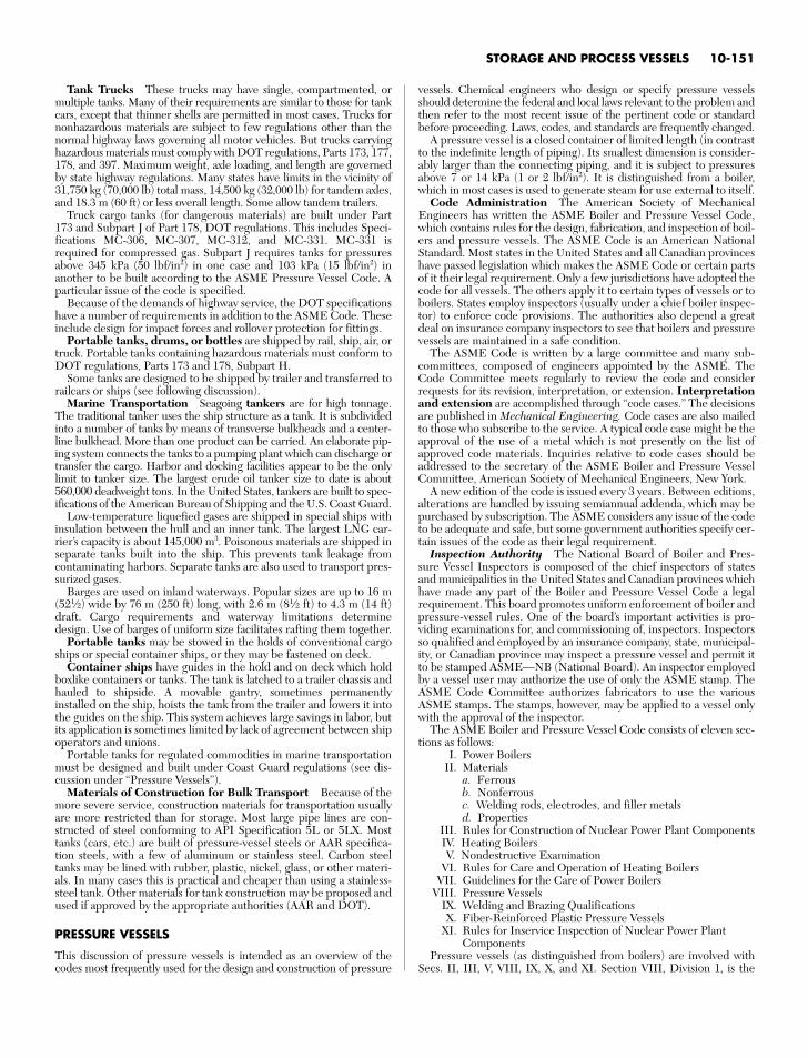
Tank Trucks These trucks may have single, compartmented, ormultiple tanks. Many of their requirements are similar to those for tankcars, except that thinner shells are permitted in most cases. Trucks fornonhazardous materials are subject to few regulations other than thenormal highway laws governing all motor vehicles. But trucks carryinghazardous materials must comply with DOT regulations, Parts 173, 177,178, and 397. Maximum weight, axle loading, and length are governedby state highway regulations. Many states have limits in the vicinity of31,750 kg (70,000 lb) total mass, 14,500 kg (32,000 lb) for tandem axles,and 18.3 m (60 ft) or less overall length. Some allow tandem trailers.
Truck cargo tanks (for dangerous materials) are built under Part173 and Subpart J of Part 178, DOT regulations. This includes Speci-fications MC-306, MC-307, MC-312, and MC-331. MC-331 isrequired for compressed gas. Subpart J requires tanks for pressuresabove 345 kPa (50 lbf/in2) in one case and 103 kPa (15 lbf/in2) inanother to be built according to the ASME Pressure Vessel Code. Aparticular issue of the code is specified.
Because of the demands of highway service, the DOT specificationshave a number of requirements in addition to the ASME Code. Theseinclude design for impact forces and rollover protection for fittings.
Portable tanks, drums, or bottles are shipped by rail, ship, air, ortruck. Portable tanks containing hazardous materials must conform toDOT regulations, Parts 173 and 178, Subpart H.
Some tanks are designed to be shipped by trailer and transferred torailcars or ships (see following discussion).
Marine Transportation Seagoing tankers are for high tonnage.The traditional tanker uses the ship structure as a tank. It is subdividedinto a number of tanks by means of transverse bulkheads and a center-line bulkhead. More than one product can be carried. An elaborate pip-ing system connects the tanks to a pumping plant which can discharge ortransfer the cargo. Harbor and docking facilities appear to be the onlylimit to tanker size. The largest crude oil tanker size to date is about560,000 deadweight tons. In the United States, tankers are built to spec-ifications of the American Bureau of Shipping and the U.S. Coast Guard.
Low-temperature liquefied gases are shipped in special ships withinsulation between the hull and an inner tank. The largest LNG car-rier’s capacity is about 145,000 m3. Poisonous materials are shipped inseparate tanks built into the ship. This prevents tank leakage fromcontaminating harbors. Separate tanks are also used to transport pres-surized gases.
Barges are used on inland waterways. Popular sizes are up to 16 m(521⁄2) wide by 76 m (250 ft) long, with 2.6 m (81⁄2 ft) to 4.3 m (14 ft)draft. Cargo requirements and waterway limitations determinedesign. Use of barges of uniform size facilitates rafting them together.
Portable tanks may be stowed in the holds of conventional cargoships or special container ships, or they may be fastened on deck.
Container ships have guides in the hold and on deck which holdboxlike containers or tanks. The tank is latched to a trailer chassis andhauled to shipside. A movable gantry, sometimes permanentlyinstalled on the ship, hoists the tank from the trailer and lowers it intothe guides on the ship. This system achieves large savings in labor, butits application is sometimes limited by lack of agreement between shipoperators and unions.
Portable tanks for regulated commodities in marine transportationmust be designed and built under Coast Guard regulations (see dis-cussion under “Pressure Vessels”).
Materials of Construction for Bulk Transport Because of themore severe service, construction materials for transportation usuallyare more restricted than for storage. Most large pipe lines are con-structed of steel conforming to API Specification 5L or 5LX. Mosttanks (cars, etc.) are built of pressure-vessel steels or AAR specifica-tion steels, with a few of aluminum or stainless steel. Carbon steeltanks may be lined with rubber, plastic, nickel, glass, or other materi-als. In many cases this is practical and cheaper than using a stainless-steel tank. Other materials for tank construction may be proposed andused if approved by the appropriate authorities (AAR and DOT).
PRESSURE VESSELS
This discussion of pressure vessels is intended as an overview of thecodes most frequently used for the design and construction of pressure
vessels. Chemical engineers who design or specify pressure vesselsshould determine the federal and local laws relevant to the problem andthen refer to the most recent issue of the pertinent code or standardbefore proceeding. Laws, codes, and standards are frequently changed.
A pressure vessel is a closed container of limited length (in contrastto the indefinite length of piping). Its smallest dimension is consider-ably larger than the connecting piping, and it is subject to pressuresabove 7 or 14 kPa (1 or 2 lbf/in2). It is distinguished from a boiler,which in most cases is used to generate steam for use external to itself.
Code Administration The American Society of MechanicalEngineers has written the ASME Boiler and Pressure Vessel Code,which contains rules for the design, fabrication, and inspection of boil-ers and pressure vessels. The ASME Code is an American NationalStandard. Most states in the United States and all Canadian provinceshave passed legislation which makes the ASME Code or certain partsof it their legal requirement. Only a few jurisdictions have adopted thecode for all vessels. The others apply it to certain types of vessels or toboilers. States employ inspectors (usually under a chief boiler inspec-tor) to enforce code provisions. The authorities also depend a greatdeal on insurance company inspectors to see that boilers and pressurevessels are maintained in a safe condition.
The ASME Code is written by a large committee and many sub-committees, composed of engineers appointed by the ASME. TheCode Committee meets regularly to review the code and considerrequests for its revision, interpretation, or extension. Interpretationand extension are accomplished through “code cases.” The decisionsare published in Mechanical Engineering. Code cases are also mailedto those who subscribe to the service. A typical code case might be theapproval of the use of a metal which is not presently on the list ofapproved code materials. Inquiries relative to code cases should beaddressed to the secretary of the ASME Boiler and Pressure VesselCommittee, American Society of Mechanical Engineers, New York.
A new edition of the code is issued every 3 years. Between editions,alterations are handled by issuing semiannual addenda, which may bepurchased by subscription. The ASME considers any issue of the codeto be adequate and safe, but some government authorities specify cer-tain issues of the code as their legal requirement.
Inspection Authority The National Board of Boiler and Pres-sure Vessel Inspectors is composed of the chief inspectors of statesand municipalities in the United States and Canadian provinces whichhave made any part of the Boiler and Pressure Vessel Code a legalrequirement. This board promotes uniform enforcement of boiler andpressure-vessel rules. One of the board’s important activities is pro-viding examinations for, and commissioning of, inspectors. Inspectorsso qualified and employed by an insurance company, state, municipal-ity, or Canadian province may inspect a pressure vessel and permit itto be stamped ASME—NB (National Board). An inspector employedby a vessel user may authorize the use of only the ASME stamp. TheASME Code Committee authorizes fabricators to use the variousASME stamps. The stamps, however, may be applied to a vessel onlywith the approval of the inspector.
The ASME Boiler and Pressure Vessel Code consists of eleven sec-tions as follows:
I. Power BoilersII. Materials
a. Ferrousb. Nonferrousc. Welding rods, electrodes, and filler metalsd. Properties
III. Rules for Construction of Nuclear Power Plant ComponentsIV. Heating BoilersV. Nondestructive Examination
VI. Rules for Care and Operation of Heating BoilersVII. Guidelines for the Care of Power Boilers
VIII. Pressure VesselsIX. Welding and Brazing QualificationsX. Fiber-Reinforced Plastic Pressure Vessels
XI. Rules for Inservice Inspection of Nuclear Power Plant Components
Pressure vessels (as distinguished from boilers) are involved withSecs. II, III, V, VIII, IX, X, and XI. Section VIII, Division 1, is the
STORAGE AND PROCESS VESSELS 10-151
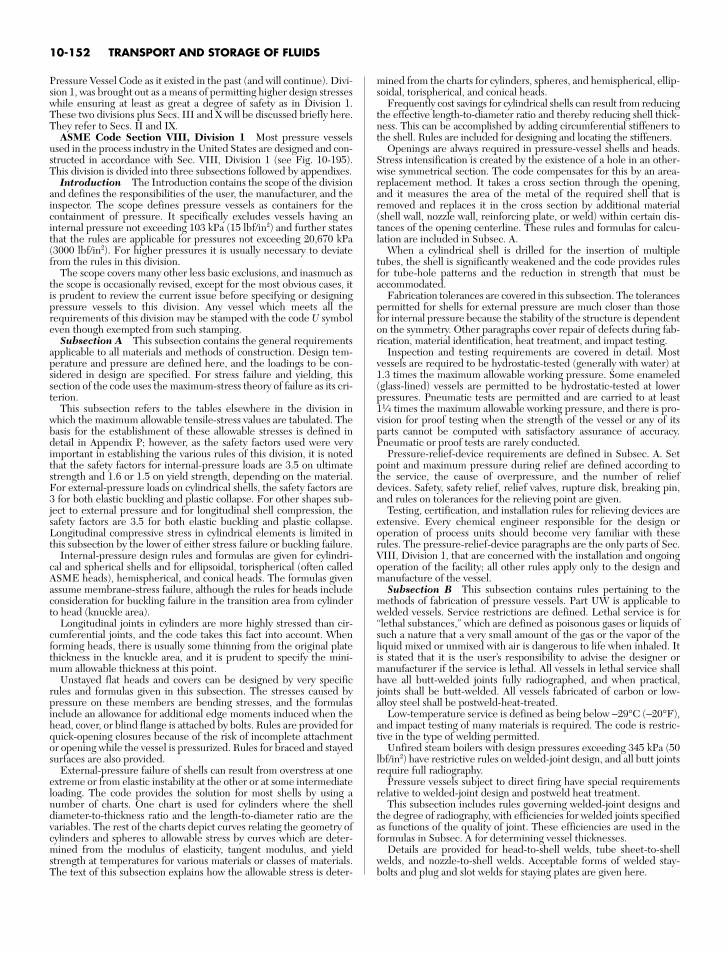
Pressure Vessel Code as it existed in the past (and will continue). Divi-sion 1, was brought out as a means of permitting higher design stresseswhile ensuring at least as great a degree of safety as in Division 1.These two divisions plus Secs. III and X will be discussed briefly here.They refer to Secs. II and IX.
ASME Code Section VIII, Division 1 Most pressure vesselsused in the process industry in the United States are designed and con-structed in accordance with Sec. VIII, Division 1 (see Fig. 10-195).This division is divided into three subsections followed by appendixes.
Introduction The Introduction contains the scope of the divisionand defines the responsibilities of the user, the manufacturer, and theinspector. The scope defines pressure vessels as containers for thecontainment of pressure. It specifically excludes vessels having aninternal pressure not exceeding 103 kPa (15 lbf/in2) and further statesthat the rules are applicable for pressures not exceeding 20,670 kPa(3000 lbf/in2). For higher pressures it is usually necessary to deviatefrom the rules in this division.
The scope covers many other less basic exclusions, and inasmuch asthe scope is occasionally revised, except for the most obvious cases, itis prudent to review the current issue before specifying or designingpressure vessels to this division. Any vessel which meets all therequirements of this division may be stamped with the code U symboleven though exempted from such stamping.
Subsection A This subsection contains the general requirementsapplicable to all materials and methods of construction. Design tem-perature and pressure are defined here, and the loadings to be con-sidered in design are specified. For stress failure and yielding, thissection of the code uses the maximum-stress theory of failure as its cri-terion.
This subsection refers to the tables elsewhere in the division inwhich the maximum allowable tensile-stress values are tabulated. Thebasis for the establishment of these allowable stresses is defined indetail in Appendix P; however, as the safety factors used were veryimportant in establishing the various rules of this division, it is notedthat the safety factors for internal-pressure loads are 3.5 on ultimatestrength and 1.6 or 1.5 on yield strength, depending on the material.For external-pressure loads on cylindrical shells, the safety factors are3 for both elastic buckling and plastic collapse. For other shapes sub-ject to external pressure and for longitudinal shell compression, thesafety factors are 3.5 for both elastic buckling and plastic collapse.Longitudinal compressive stress in cylindrical elements is limited inthis subsection by the lower of either stress failure or buckling failure.
Internal-pressure design rules and formulas are given for cylindri-cal and spherical shells and for ellipsoidal, torispherical (often calledASME heads), hemispherical, and conical heads. The formulas givenassume membrane-stress failure, although the rules for heads includeconsideration for buckling failure in the transition area from cylinderto head (knuckle area).
Longitudinal joints in cylinders are more highly stressed than cir-cumferential joints, and the code takes this fact into account. Whenforming heads, there is usually some thinning from the original platethickness in the knuckle area, and it is prudent to specify the mini-mum allowable thickness at this point.
Unstayed flat heads and covers can be designed by very specificrules and formulas given in this subsection. The stresses caused bypressure on these members are bending stresses, and the formulasinclude an allowance for additional edge moments induced when thehead, cover, or blind flange is attached by bolts. Rules are provided forquick-opening closures because of the risk of incomplete attachmentor opening while the vessel is pressurized. Rules for braced and stayedsurfaces are also provided.
External-pressure failure of shells can result from overstress at oneextreme or from elastic instability at the other or at some intermediateloading. The code provides the solution for most shells by using anumber of charts. One chart is used for cylinders where the shelldiameter-to-thickness ratio and the length-to-diameter ratio are thevariables. The rest of the charts depict curves relating the geometry ofcylinders and spheres to allowable stress by curves which are deter-mined from the modulus of elasticity, tangent modulus, and yieldstrength at temperatures for various materials or classes of materials.The text of this subsection explains how the allowable stress is deter-
mined from the charts for cylinders, spheres, and hemispherical, ellip-soidal, torispherical, and conical heads.
Frequently cost savings for cylindrical shells can result from reducingthe effective length-to-diameter ratio and thereby reducing shell thick-ness. This can be accomplished by adding circumferential stiffeners tothe shell. Rules are included for designing and locating the stiffeners.
Openings are always required in pressure-vessel shells and heads.Stress intensification is created by the existence of a hole in an other-wise symmetrical section. The code compensates for this by an area-replacement method. It takes a cross section through the opening,and it measures the area of the metal of the required shell that isremoved and replaces it in the cross section by additional material(shell wall, nozzle wall, reinforcing plate, or weld) within certain dis-tances of the opening centerline. These rules and formulas for calcu-lation are included in Subsec. A.
When a cylindrical shell is drilled for the insertion of multipletubes, the shell is significantly weakened and the code provides rulesfor tube-hole patterns and the reduction in strength that must beaccommodated.
Fabrication tolerances are covered in this subsection. The tolerancespermitted for shells for external pressure are much closer than thosefor internal pressure because the stability of the structure is dependenton the symmetry. Other paragraphs cover repair of defects during fab-rication, material identification, heat treatment, and impact testing.
Inspection and testing requirements are covered in detail. Mostvessels are required to be hydrostatic-tested (generally with water) at1.3 times the maximum allowable working pressure. Some enameled(glass-lined) vessels are permitted to be hydrostatic-tested at lowerpressures. Pneumatic tests are permitted and are carried to at least11⁄4 times the maximum allowable working pressure, and there is pro-vision for proof testing when the strength of the vessel or any of itsparts cannot be computed with satisfactory assurance of accuracy.Pneumatic or proof tests are rarely conducted.
Pressure-relief-device requirements are defined in Subsec. A. Setpoint and maximum pressure during relief are defined according tothe service, the cause of overpressure, and the number of reliefdevices. Safety, safety relief, relief valves, rupture disk, breaking pin,and rules on tolerances for the relieving point are given.
Testing, certification, and installation rules for relieving devices areextensive. Every chemical engineer responsible for the design oroperation of process units should become very familiar with theserules. The pressure-relief-device paragraphs are the only parts of Sec.VIII, Division 1, that are concerned with the installation and ongoingoperation of the facility; all other rules apply only to the design andmanufacture of the vessel.
Subsection B This subsection contains rules pertaining to themethods of fabrication of pressure vessels. Part UW is applicable towelded vessels. Service restrictions are defined. Lethal service is for“lethal substances,” which are defined as poisonous gases or liquids ofsuch a nature that a very small amount of the gas or the vapor of theliquid mixed or unmixed with air is dangerous to life when inhaled. Itis stated that it is the user’s responsibility to advise the designer ormanufacturer if the service is lethal. All vessels in lethal service shallhave all butt-welded joints fully radiographed, and when practical,joints shall be butt-welded. All vessels fabricated of carbon or low-alloy steel shall be postweld-heat-treated.
Low-temperature service is defined as being below −29°C (−20°F),and impact testing of many materials is required. The code is restric-tive in the type of welding permitted.
Unfired steam boilers with design pressures exceeding 345 kPa (50lbf/in2) have restrictive rules on welded-joint design, and all butt jointsrequire full radiography.
Pressure vessels subject to direct firing have special requirementsrelative to welded-joint design and postweld heat treatment.
This subsection includes rules governing welded-joint designs andthe degree of radiography, with efficiencies for welded joints specifiedas functions of the quality of joint. These efficiencies are used in theformulas in Subsec. A for determining vessel thicknesses.
Details are provided for head-to-shell welds, tube sheet-to-shellwelds, and nozzle-to-shell welds. Acceptable forms of welded stay-bolts and plug and slot welds for staying plates are given here.
10-152 TRANSPORT AND STORAGE OF FLUIDS
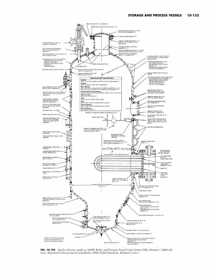
STORAGE AND PROCESS VESSELS 10-153
FIG. 10-195 Quick reference guide to ASME Boiler and Pressure Vessel Code Section VIII, Division 1 (2004 edi-tion). (Reprinted with permission of publisher, HSB Global Standards, Hartford, Conn.)
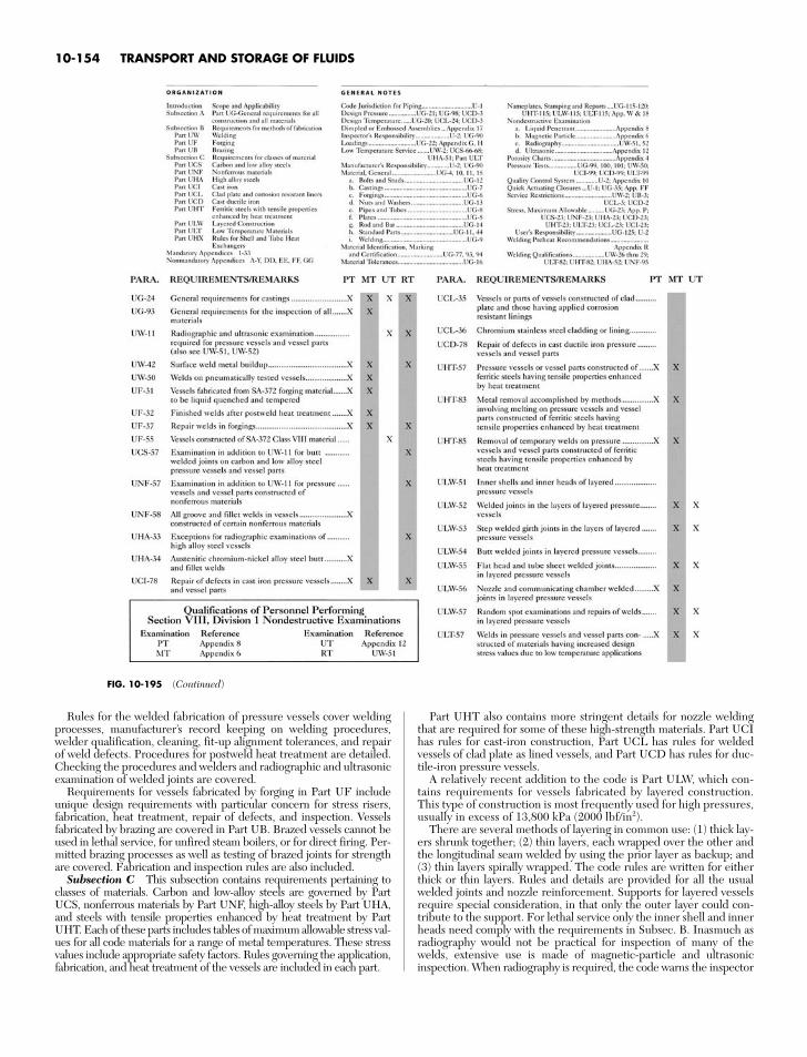
Rules for the welded fabrication of pressure vessels cover weldingprocesses, manufacturer’s record keeping on welding procedures,welder qualification, cleaning, fit-up alignment tolerances, and repairof weld defects. Procedures for postweld heat treatment are detailed.Checking the procedures and welders and radiographic and ultrasonicexamination of welded joints are covered.
Requirements for vessels fabricated by forging in Part UF includeunique design requirements with particular concern for stress risers,fabrication, heat treatment, repair of defects, and inspection. Vesselsfabricated by brazing are covered in Part UB. Brazed vessels cannot beused in lethal service, for unfired steam boilers, or for direct firing. Per-mitted brazing processes as well as testing of brazed joints for strengthare covered. Fabrication and inspection rules are also included.
Subsection C This subsection contains requirements pertaining toclasses of materials. Carbon and low-alloy steels are governed by PartUCS, nonferrous materials by Part UNF, high-alloy steels by Part UHA,and steels with tensile properties enhanced by heat treatment by PartUHT. Each of these parts includes tables of maximum allowable stress val-ues for all code materials for a range of metal temperatures. These stressvalues include appropriate safety factors. Rules governing the application,fabrication, and heat treatment of the vessels are included in each part.
Part UHT also contains more stringent details for nozzle weldingthat are required for some of these high-strength materials. Part UCIhas rules for cast-iron construction, Part UCL has rules for weldedvessels of clad plate as lined vessels, and Part UCD has rules for duc-tile-iron pressure vessels.
A relatively recent addition to the code is Part ULW, which con-tains requirements for vessels fabricated by layered construction.This type of construction is most frequently used for high pressures,usually in excess of 13,800 kPa (2000 lbf/in2).
There are several methods of layering in common use: (1) thick lay-ers shrunk together; (2) thin layers, each wrapped over the other andthe longitudinal seam welded by using the prior layer as backup; and(3) thin layers spirally wrapped. The code rules are written for eitherthick or thin layers. Rules and details are provided for all the usualwelded joints and nozzle reinforcement. Supports for layered vesselsrequire special consideration, in that only the outer layer could con-tribute to the support. For lethal service only the inner shell and innerheads need comply with the requirements in Subsec. B. Inasmuch asradiography would not be practical for inspection of many of thewelds, extensive use is made of magnetic-particle and ultrasonicinspection. When radiography is required, the code warns the inspector
10-154 TRANSPORT AND STORAGE OF FLUIDS
FIG. 10-195 (Continued)
that indications sufficient for rejection in single-wall vessels may beacceptable. Vent holes are specified through each layer down to theinner shell to prevent buildup of pressure between layers in the eventof leakage at the inner shell.
Mandatory Appendixes These include a section on supplemen-tary design formulas for shells not covered in Subsec. A. Formulas aregiven for thick shells, heads, and dished covers. Another appendix givesvery specific rules, formulas, and charts for the design of bolted-flangeconnections. The nature of these rules is such that they are readily pro-grammable for a digital computer, and most flanges now are designedby using computers. One appendix includes only the charts used forcalculating shells for external pressure discussed previously. Jacketedvessels are covered in a separate appendix in which very specific rulesare given, particularly for the attachment of the jacket to the innershell. Other appendixes cover inspection and quality control.
Nonmandatory Appendixes These cover a number of subjects,primarily suggested good practices and other aids in understandingthe code and in designing with the code. Several current nonmanda-tory appendixes will probably become mandatory.
Figure 10-195 illustrates a pressure vessel with the applicable codeparagraphs noted for the various elements. Additional important para-graphs are referenced at the bottom of the figure.
ASME Code Section VIII, Division 2 Paragraph AG-100e ofDivision 2 states: “In relation to the rules of Division 1 of Section VIII,these rules of Division 2 are more restrictive in the choice of materi-als which may be used but permit higher design stress intensity valuesto be employed in the range of temperatures over which the designstress intensity value is controlled by the ultimate strength or the yieldstrength; more precise design procedures are required and somecommon design details are prohibited; permissible fabrication proce-dures are specifically delineated and more complete testing andinspection are required.” Most Division 2 vessels fabricated to datehave been large or intended for high pressure and, therefore, expen-sive when the material and labor savings resulting from smaller safetyfactors have been greater than the additional engineering, administra-tive, and inspection costs.
The organization of Division 2 differs from that of Division 1.Part AG This part gives the scope of the division, establishes its
jurisdiction, and sets forth the responsibilities of the user and the man-ufacturer. Of particular importance is the fact that no upper limitationin pressure is specified and that a user’s design specification is required.The user or the user’s agent shall provide requirements for intendedoperating conditions in such detail as to constitute an adequate basis forselecting materials and designing, fabricating, and inspecting the vessel.The user’s design specification shall include the method of supportingthe vessel and any requirement for a fatigue analysis. If a fatigue analy-sis is required, the user must provide information in sufficient detail sothat an analysis for cyclic operation can be made.
Part AM This part lists permitted individual construction materials,applicable specifications, special requirements, design stress-intensityvalues, and other property information. Of particular importance are theultrasonic-test and toughness requirements. Among the properties forwhich data are included are thermal conductivity and diffusivity, coeffi-cient of thermal expansion, modulus of elasticity, and yield strength. Thedesign stress-intensity values include a safety factor of 3 on ultimatestrength at temperature or 1.5 on yield strength at temperature.
Part AD This part contains requirements for the design of ves-sels. The rules of Division 2 are based on the maximum-shear theoryof failure for stress failure and yielding. Higher stresses are permittedwhen wind or earthquake loads are considered. Any rules for deter-mining the need for fatigue analysis are given here.
Rules for the design of shells of revolution under internal pressurediffer from the Division 1 rules, particularly the rules for formedheads when plastic deformation in the knuckle area is the failure cri-terion. Shells of revolution for external pressure are determined onthe same criterion, including safety factors, as in Division 1. Rein-forcement for openings uses the same area-replacement method asDivision 1; however, in many cases the reinforcement metal must becloser to the opening centerline.
The rest of the rules in Part AD for flat heads, bolted and studdedconnections, quick-actuating closures, and layered vessels essentially
duplicate Division 1. The rules for support skirts are more definitivein Division 2.
Part AF This part contains requirements governing the fabrica-tion of vessels and vessel parts.
Part AR This part contains rules for pressure-relieving devices.Part AI This part contains requirements controlling inspection of
vessel.Part AT This part contains testing requirements and procedures.Part AS This part contains requirements for stamping and certi-
fying the vessel and vessel parts.Appendixes Appendix 1 defines the basis used for defining
stress-intensity values. Appendix 2 contains external-pressure charts,and Appendix 3 has the rules for bolted-flange connections; these twoare exact duplicates of the equivalent appendixes in Division 1.
Appendix 4 gives definitions and rules for stress analysis for shells, flatand formed heads, and tube sheets, layered vessels, and nozzles includ-ing discontinuity stresses. Of particular importance are Table 4-120.1,“Classification of Stresses for Some Typical Cases,” and Fig. 4-130.1,“Stress Categories and Limits of Stress Intensity.” These are very usefulin that they clarify a number of paragraphs and simplify stress analysis.
Appendix 5 contains rules and data for stress analysis for cyclic oper-ation. Except in short-cycle batch processes, pressure vessels are usuallysubject to few cycles in their projected lifetime, and the endurance-limit data used in the machinery industries are not applicable. Curvesare given for a broad spectrum of materials, covering a range from 10 to1 million cycles with allowable stress values as high as 650,000 lbf/in2.This low-cycle fatigue has been developed from strain-fatigue work inwhich stress values are obtained by multiplying the strains by the mod-ulus of elasticity. Stresses of this magnitude cannot occur, but strains do.The curves given have a factor of safety of 2 on stress or 20 on cycles.
Appendix 6 contains requirements of experimental stress analysis,Appendix 8 has acceptance standards for radiographic examination,Appendix 9 covers nondestructive examination, Appendix 10 givesrules for capacity conversions for safety valves, and Appendix 18details quality-control-system requirements.
The remaining appendixes are nonmandatory but useful to engi-neers working with the code.
General Considerations Most pressure vessels for the chemi-cal-process industry will continue to be designed and built to the rulesof Sec. VIII, Division 1. While the rules of Sec. VIII, Division 2, willfrequently provide thinner elements, the cost of the engineeringanalysis, stress analysis and higher-quality construction, material con-trol, and inspection required by these rules frequently exceeds thesavings from the use of thinner walls.
Additional ASME Code ConsiderationsASME Code Sec. III: Nuclear Power Plant Components This
section of the code includes vessels, storage tanks, and concrete con-tainment vessels as well as other nonvessel items.
ASME Code Sec. X: Fiberglass–Reinforced-Plastic PressureVessels This section is limited to four types of vessels: bag-moldedand centrifugally cast, each limited to 1000 kPa (150 lbf/in2); filament-wound with cut filaments limited to 10,000 kPa (1500 lbf/in2); and fila-ment-wound with uncut filaments limited to 21,000 kPa (3000 lbf/in2).Operating temperatures are limited to the range from +66°C (150°F) to−54°C (−65°F). Low modulus of elasticity and other property differ-ences between metal and plastic required that many of the proceduresin Sec. X be different from those in the sections governing metal vessels.The requirement that at least one vessel of a particular design and fab-rication shall be tested to destruction has prevented this section frombeing widely used. The results from the combined fatigue and burst testmust give the design pressure a safety factor of 6 to the burst pressure.
Safety in Design Designing a pressure vessel in accordance withthe code will, under most circumstances, provide adequate safety. Inthe code’s own words, however, the rules “cover minimum construc-tion requirements for the design, fabrication, inspection, and certifi-cation of pressure vessels.” The significant word is “minimum.” Theultimate responsibility for safety rests with the user and thedesigner. They must decide whether anything beyond code require-ments is necessary. The code cannot foresee and provide for all the
STORAGE AND PROCESS VESSELS 10-155
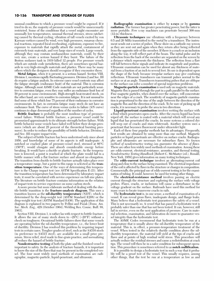
unusual conditions to which a pressure vessel might be exposed. If ittried to do so, the majority of pressure vessels would be unnecessarilyrestricted. Some of the conditions that a vessel might encounter areunusually low temperatures, unusual thermal stresses, stress ratchet-ing caused by thermal cycling, vibration of tall vessels excited by vonKarman vortices caused by wind, very high pressures, runaway chem-ical reactions, repeated local overheating, explosions, exposure to fire,exposure to materials that rapidly attack the metal, containment ofextremely toxic materials, and very large sizes of vessels. Large vessels,although they may contain nonhazardous materials, could, by theirvery size, create a serious hazard if they burst. The failure of theBoston molasses tank in 1919 killed 12 people. For pressure vesselswhich are outside code jurisdiction, there are sometimes special haz-ards in very-high-strength materials and plastics. There may be manyothers which the designers should recognize if they encounter them.
Metal fatigue, when it is present, is a serious hazard. Section VIII,Division 1, mentions rapidly fluctuating pressures. Division 2 and Sec. IIIdo require a fatigue analysis. In extreme cases vessel contents may affectthe fatigue strength (endurance limit) of the material. This is corrosionfatigue. Although most ASME Code materials are not particularly sensi-tive to corrosion fatigue, even they may suffer an endurance limit loss of50 percent in some environments. High-strength heat-treated steels, onthe other hand, are very sensitive to corrosion fatigue. It is not unusual tofind some of these which lose 75 percent of their endurance in corrosiveenvironments. In fact, in corrosion fatigue many steels do not have anendurance limit. The curve of stress versus cycles to failure (S/N curve)continues to slope downward regardless of the number of cycles.
Brittle fracture is probably the most insidious type of pressure-vessel failure. Without brittle fracture, a pressure vessel could bepressurized approximately to its ultimate strength before failure. Withbrittle behavior some vessels have failed well below their design pres-sures (which are about 25 percent of the theoretical bursting pres-sures). In order to reduce the possibility of brittle behavior, Division 2and Sec. III require impact tests.
The subject of brittle fracture has been understood only since about1950, and knowledge of some of its aspects is still inadequate. Anotched or cracked plate of pressure-vessel steel, stressed at 66°C(150°F), would elongate and absorb considerable energy beforebreaking. It would have a ductile or plastic fracture. As the tempera-ture is lowered, a point is reached at which the plate would fail in abrittle manner with a flat fracture surface and almost no elongation.The transition from ductile to brittle fracture actually takes place overa temperature range, but a point in this range is selected as the tran-sition temperature. One of the ways of determining this tempera-ture is the Charpy impact test (see ASTM Specification E-23). Afterthe transition temperature has been determined by laboratory impacttests, it must be correlated with service experience on full-size plates.The literature on brittle fracture contains information on the relationof impact tests to service experience on some carbon steels.
A more precise but more elaborate method of dealing with the duc-tile-brittle transition is the fracture-analysis diagram. This uses atransition known as the nil-ductility temperature (NDT), which isdetermined by the drop-weight test (ASTM Standard E208) or thedrop-weight tear test (ASTM Standard E436). The application of thisdiagram is explained in two papers by Pellini and Puzak [Trans. Am.Soc. Mech. Eng., 429 (October 1964); Welding Res. Counc. Bull. 88,1963].
Section VIII, Division 1, is rather lax with respect to brittle fracture.It allows the use of many steels down to −29°C (−20°F) without acheck on toughness. Occasional brittle failures show that some vesselsare operating below the nil-ductility temperature, i.e., the lower limitof ductility. Division 2 has resolved this problem by requiring impacttests in certain cases. Tougher grades of steel, such as the SA516 steels(in preference to SA515 steel), are available for a small price pre-mium. Stress relief, steel made to fine-grain practice, and normalizingall reduce the hazard of brittle fracture.
Nondestructive testing of both the plate and the finished vessel isimportant to safety. In the analysis of fracture hazards, it is importantto know the size of the flaws that may be present in the completed ves-sel. The four most widely used methods of examination are radi-ographic, magnetic-particle, liquid-penetrant, and ultrasonic.
Radiographic examination is either by x-rays or by gammaradiation. The former has greater penetrating power, but the latter ismore portable. Few x-ray machines can penetrate beyond 300-mm(12-in) thickness.
Ultrasonic techniques use vibrations with a frequency between0.5 and 20 MHz transmitted to the metal by a transducer. The instru-ment sends out a series of pulses. These show on a cathode-ray screenas they are sent out and again when they return after being reflectedfrom the opposite side of the member. If there is a crack or an inclusionalong the way, it will reflect part of the beam. The initial pulse and itsreflection from the back of the member are separated on the screen bya distance which represents the thickness. The reflection from a flawwill fall between these signals and indicate its magnitude and position.Ultrasonic examination can be used for almost any thickness of mate-rial from a fraction of an inch to several feet. Its use is dependent uponthe shape of the body because irregular surfaces may give confusingreflections. Ultrasonic transducers can transmit pulses normal to thesurface or at an angle. Transducers transmitting pulses that are obliqueto the surface can solve a number of special inspection problems.
Magnetic-particle examination is used only on magnetic materials.Magnetic flux is passed through the part in a path parallel to the surface.Fine magnetic particles, when dusted over the surface, will concentratenear the edges of a crack. The sensitivity of magnetic-particle examina-tion is proportional to the sine of the angle between the direction of themagnetic flux and the direction of the crack. To be sure of picking up allcracks, it is necessary to probe the area in two directions.
Liquid-penetrant examination involves wetting the surface witha fluid which penetrates open cracks. After the excess liquid has beenwiped off, the surface is coated with a material which will reveal anyliquid that has penetrated the cracks. In some systems a colored dyewill seep out of cracks and stain whitewash. Another system uses apenetrant that becomes fluorescent under ultraviolet light.
Each of these four popular methods has its advantages. Frequently,best results are obtained by using more than one method. Magneticparticles or liquid penetrants are effective on surface cracks. Radiogra-phy and ultrasonics are necessary for subsurface flaws. No knownmethod of nondestructive testing can guarantee the absence of flaws.There are other less widely used methods of examination. Among theseare eddy-current, electrical-resistance, acoustics, and thermal testing.Nondestructive Testing Handbook [Robert C. McMaster (ed.), Ronald,New York, 1959] gives information on many testing techniques.
The eddy-current technique involves an alternating-current coilalong and close to the surface being examined. The electrical impedanceof the coil is affected by flaws in the structure or changes in composition.Commercially, the principal use of eddy-current testing is for the exami-nation of tubing. It could, however, be used for testing other things.
The electrical-resistance method involves passing an electriccurrent through the structure and exploring the surface with voltageprobes. Flaws, cracks, or inclusions will cause a disturbance in thevoltage gradient on the surface. Railroads have used this method formany years to locate transverse cracks in rails.
The hydrostatic test is, in one sense, a method of examination of avessel. It can reveal gross flaws, inadequate design, and flange leaks.Many believe that a hydrostatic test guarantees the safety of a vessel.This is not necessarily so. A vessel that has passed a hydrostatic test isprobably safer than one that has not been tested. It can, however, stillfail in service, even on the next application of pressure. Care in mate-rial selection, examination, and fabrication do more to guarantee ves-sel integrity than the hydrostatic test.
The ASME Codes recommend that hydrostatic tests be run at atemperature that is usually above the nil-ductility temperature of thematerial. This is, in effect, a pressure-temperature treatment of thevessel. When tested in the relatively ductile condition above the nil-ductility temperature, the material will yield at the tips of cracks andflaws and at points of high residual weld stress. This procedure willactually reduce the residual stresses and cause a redistribution at cracktips. The vessel will then be in a safer condition for subsequent opera-tion. This procedure is sometimes referred to as notch nullification.
It is possible to design a hydrostatic test in such a way that it proba-bly will be a proof test of the vessel. This usually requires, amongother things, that the test be run at a temperature as low as and
10-156 TRANSPORT AND STORAGE OF FLUIDS
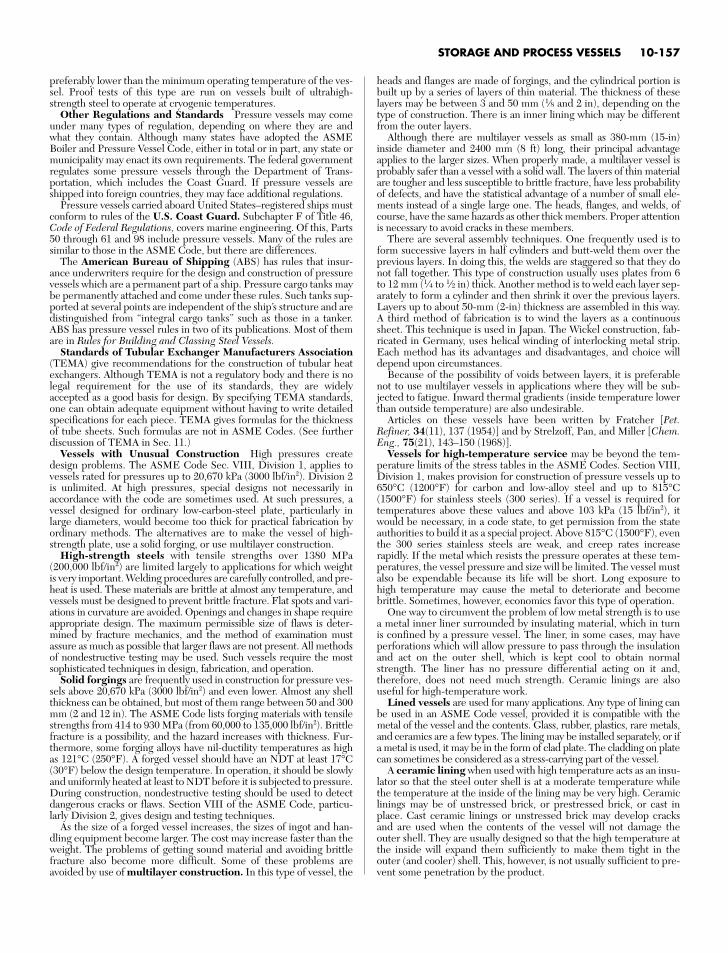
preferably lower than the minimum operating temperature of the ves-sel. Proof tests of this type are run on vessels built of ultrahigh-strength steel to operate at cryogenic temperatures.
Other Regulations and Standards Pressure vessels may comeunder many types of regulation, depending on where they are andwhat they contain. Although many states have adopted the ASMEBoiler and Pressure Vessel Code, either in total or in part, any state ormunicipality may enact its own requirements. The federal governmentregulates some pressure vessels through the Department of Trans-portation, which includes the Coast Guard. If pressure vessels areshipped into foreign countries, they may face additional regulations.
Pressure vessels carried aboard United States–registered ships mustconform to rules of the U.S. Coast Guard. Subchapter F of Title 46,Code of Federal Regulations, covers marine engineering. Of this, Parts50 through 61 and 98 include pressure vessels. Many of the rules aresimilar to those in the ASME Code, but there are differences.
The American Bureau of Shipping (ABS) has rules that insur-ance underwriters require for the design and construction of pressurevessels which are a permanent part of a ship. Pressure cargo tanks maybe permanently attached and come under these rules. Such tanks sup-ported at several points are independent of the ship’s structure and aredistinguished from “integral cargo tanks” such as those in a tanker.ABS has pressure vessel rules in two of its publications. Most of themare in Rules for Building and Classing Steel Vessels.
Standards of Tubular Exchanger Manufacturers Association(TEMA) give recommendations for the construction of tubular heatexchangers. Although TEMA is not a regulatory body and there is nolegal requirement for the use of its standards, they are widelyaccepted as a good basis for design. By specifying TEMA standards,one can obtain adequate equipment without having to write detailedspecifications for each piece. TEMA gives formulas for the thicknessof tube sheets. Such formulas are not in ASME Codes. (See furtherdiscussion of TEMA in Sec. 11.)
Vessels with Unusual Construction High pressures createdesign problems. The ASME Code Sec. VIII, Division 1, applies tovessels rated for pressures up to 20,670 kPa (3000 lbf/in2). Division 2is unlimited. At high pressures, special designs not necessarily inaccordance with the code are sometimes used. At such pressures, avessel designed for ordinary low-carbon-steel plate, particularly inlarge diameters, would become too thick for practical fabrication byordinary methods. The alternatives are to make the vessel of high-strength plate, use a solid forging, or use multilayer construction.
High-strength steels with tensile strengths over 1380 MPa(200,000 lbf/in2) are limited largely to applications for which weightis very important. Welding procedures are carefully controlled, and pre-heat is used. These materials are brittle at almost any temperature, andvessels must be designed to prevent brittle fracture. Flat spots and vari-ations in curvature are avoided. Openings and changes in shape requireappropriate design. The maximum permissible size of flaws is deter-mined by fracture mechanics, and the method of examination mustassure as much as possible that larger flaws are not present. All methodsof nondestructive testing may be used. Such vessels require the mostsophisticated techniques in design, fabrication, and operation.
Solid forgings are frequently used in construction for pressure ves-sels above 20,670 kPa (3000 lbf/in2) and even lower. Almost any shellthickness can be obtained, but most of them range between 50 and 300mm (2 and 12 in). The ASME Code lists forging materials with tensilestrengths from 414 to 930 MPa (from 60,000 to 135,000 lbf/in2). Brittlefracture is a possibility, and the hazard increases with thickness. Fur-thermore, some forging alloys have nil-ductility temperatures as highas 121°C (250°F). A forged vessel should have an NDT at least 17°C(30°F) below the design temperature. In operation, it should be slowlyand uniformly heated at least to NDT before it is subjected to pressure.During construction, nondestructive testing should be used to detectdangerous cracks or flaws. Section VIII of the ASME Code, particu-larly Division 2, gives design and testing techniques.
As the size of a forged vessel increases, the sizes of ingot and han-dling equipment become larger. The cost may increase faster than theweight. The problems of getting sound material and avoiding brittlefracture also become more difficult. Some of these problems areavoided by use of multilayer construction. In this type of vessel, the
heads and flanges are made of forgings, and the cylindrical portion isbuilt up by a series of layers of thin material. The thickness of theselayers may be between 3 and 50 mm (1⁄8 and 2 in), depending on thetype of construction. There is an inner lining which may be differentfrom the outer layers.
Although there are multilayer vessels as small as 380-mm (15-in)inside diameter and 2400 mm (8 ft) long, their principal advantageapplies to the larger sizes. When properly made, a multilayer vessel isprobably safer than a vessel with a solid wall. The layers of thin materialare tougher and less susceptible to brittle fracture, have less probabilityof defects, and have the statistical advantage of a number of small ele-ments instead of a single large one. The heads, flanges, and welds, ofcourse, have the same hazards as other thick members. Proper attentionis necessary to avoid cracks in these members.
There are several assembly techniques. One frequently used is toform successive layers in half cylinders and butt-weld them over theprevious layers. In doing this, the welds are staggered so that they donot fall together. This type of construction usually uses plates from 6to 12 mm (1⁄4 to 1⁄2 in) thick. Another method is to weld each layer sep-arately to form a cylinder and then shrink it over the previous layers.Layers up to about 50-mm (2-in) thickness are assembled in this way.A third method of fabrication is to wind the layers as a continuoussheet. This technique is used in Japan. The Wickel construction, fab-ricated in Germany, uses helical winding of interlocking metal strip.Each method has its advantages and disadvantages, and choice willdepend upon circumstances.
Because of the possibility of voids between layers, it is preferablenot to use multilayer vessels in applications where they will be sub-jected to fatigue. Inward thermal gradients (inside temperature lowerthan outside temperature) are also undesirable.
Articles on these vessels have been written by Fratcher [Pet.Refiner, 34(11), 137 (1954)] and by Strelzoff, Pan, and Miller [Chem.Eng., 75(21), 143–150 (1968)].
Vessels for high-temperature service may be beyond the tem-perature limits of the stress tables in the ASME Codes. Section VIII,Division 1, makes provision for construction of pressure vessels up to650°C (1200°F) for carbon and low-alloy steel and up to 815°C(1500°F) for stainless steels (300 series). If a vessel is required fortemperatures above these values and above 103 kPa (15 lbf/in2), itwould be necessary, in a code state, to get permission from the stateauthorities to build it as a special project. Above 815°C (1500°F), eventhe 300 series stainless steels are weak, and creep rates increaserapidly. If the metal which resists the pressure operates at these tem-peratures, the vessel pressure and size will be limited. The vessel mustalso be expendable because its life will be short. Long exposure tohigh temperature may cause the metal to deteriorate and becomebrittle. Sometimes, however, economics favor this type of operation.
One way to circumvent the problem of low metal strength is to usea metal inner liner surrounded by insulating material, which in turnis confined by a pressure vessel. The liner, in some cases, may haveperforations which will allow pressure to pass through the insulationand act on the outer shell, which is kept cool to obtain normalstrength. The liner has no pressure differential acting on it and,therefore, does not need much strength. Ceramic linings are alsouseful for high-temperature work.
Lined vessels are used for many applications. Any type of lining canbe used in an ASME Code vessel, provided it is compatible with themetal of the vessel and the contents. Glass, rubber, plastics, rare metals,and ceramics are a few types. The lining may be installed separately, or ifa metal is used, it may be in the form of clad plate. The cladding on platecan sometimes be considered as a stress-carrying part of the vessel.
A ceramic lining when used with high temperature acts as an insu-lator so that the steel outer shell is at a moderate temperature whilethe temperature at the inside of the lining may be very high. Ceramiclinings may be of unstressed brick, or prestressed brick, or cast inplace. Cast ceramic linings or unstressed brick may develop cracksand are used when the contents of the vessel will not damage theouter shell. They are usually designed so that the high temperature atthe inside will expand them sufficiently to make them tight in theouter (and cooler) shell. This, however, is not usually sufficient to pre-vent some penetration by the product.
STORAGE AND PROCESS VESSELS 10-157
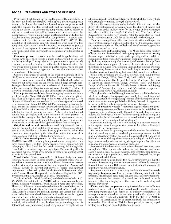
Prestressed-brick linings can be used to protect the outer shell. Inthis case, the bricks are installed with a special thermosetting-resinmortar. After lining, the vessel is subjected to internal pressure andheat. This expands the steel vessel shell, and the mortar expands totake up the space. The pressure and temperature must be at least ashigh as the maximum that will be encountered in service. After themortar has set, reduction of pressure and temperature will allow thevessel to contract, putting the brick in compression. The upper tem-perature limit for this construction is about 190°C (375°F). Theinstallation of such linings is highly specialized work done by a fewcompanies. Great care is usually exercised in operation to protectthe vessel from exposure to unsymmetrical temperature gradients.Side nozzles and other unsymmetrical designs are avoided insofar aspossible.
Concrete pressure vessels may be used in applications thatrequire large sizes. Such vessels, if made of steel, would be too largeand heavy to ship. Through the use of posttensioned (prestressed)concrete, the vessel is fabricated on the site. In this construction, thereinforcing steel is placed in tubes or plastic covers, which are castinto the concrete. Tension is applied to the steel after the concrete hasacquired most of its strength.
Concrete nuclear reactor vessels, of the order of magnitude of 15-m(50-ft) inside diameter and length, have inner linings of steel which con-fine the pressure. After fabrication of the liner, the tubes for the cables orwires are put in place and the concrete is poured. High-strength rein-forcing steel is used. Because there are thousands of reinforcing tendonsin the concrete vessel, there is a statistical factor of safety. The failure of1 or even 10 tendons would have little effect on the overall structure.
Plastic pressure vessels have the advantages of chemical resistanceand light weight. Above 103 kPa (15 lbf/in2), with certain exceptions,they must be designed according to the ASME Code Section X (see“Storage of Gases”) and are confined to the three types of approvedcode construction. Below 103 kPa (15 lbf/in2), any construction may beused. Even in this pressure range, however, the code should be used forguidance. Solid plastics, because of low strength and creep, can be usedonly for the lowest pressures and sizes. A stress of a few hundredpounds-force per square inch is the maximum for most plastics. Toobtain higher strength, the filled plastics or filament-wound vessels,specified by the code, must be used. Solid-plastic parts, however, areoften employed inside a steel shell, particularly for heat exchangers.
Graphite and ceramic vessels are used fully armored; that is,they are enclosed within metal pressure vessels. These materials arealso used for boxlike vessels with backing plates on the sides. Theplates are drawn together by tie bolts, thus putting the material incompression so that it can withstand low pressure.
ASME Code Developments At the time of this publication,ASME Section VIII is currently being rewritten and reorganized intothree classes. Class 1 will be for low-pressure vessels employing spotradiography. Class 2 will be for vessels requiring full radiography.Class 3 will be for vessels experiencing fatigue. This rewriting effort isalso using material stress levels similar to those of competing vesselcodes from Europe and Asia.
Vessel Codes Other than ASME Different design and con-struction rules are used in other countries. Chemical engineers con-cerned with pressure vessels outside the United States must becomefamiliar with local pressure-vessel laws and regulations. Boilers andPressure Vessels, an international survey of design and approvalrequirements published by the British Standards Institution, May-lands Avenue, Hemel Hempstead, Hertfordshire, England, in 1975,gives pertinent information for 76 political jurisdictions.
The British Code (British Standards) and the German Code (A. D.Merkblätter) in addition to the ASME Code are most commonly per-mitted, although Netherlands, Sweden, and France also have codes.The major difference between the codes lies in factors of safety and inwhether or not ultimate strength is considered. ASME Code, Sec.VIII, Division 1, vessels are generally heavier than vessels built to theother codes; however, the differences in allowable stress for a givenmaterial are less in the higher temperature (creep) range.
Engineers and metallurgists have developed alloys to comply eco-nomically with individual codes. In Germany, where design stress isdetermined from yield strength and creep-rupture strength and no
allowance is made for ultimate strength, steels which have a very highyield-strength-to-ultimate-strength ratio are used.
Other differences between codes include different bases for thedesign of reinforcement for openings and the design of flanges andheads. Some codes include rules for the design of heat-exchangertube sheets, while others (ASME Code) do not. The Dutch Code(Grondslagen) includes very specific rules for calculation of windloads, while the ASME Code leaves this entirely to the designer.
There are also significant differences in construction and inspectionrules. Unless engineers make a detailed study of the individual codesand keep current, they will be well advised to make use of responsibleexperts for any of the codes.
Vessel Design and Construction The ASME Code lists a numberof loads that must be considered in designing a pressure vessel. Amongthem are impact, weight of the vessel under operating and test conditions,superimposed loads from other equipment and piping, wind and earth-quake loads, temperature-gradient stresses, and localized loadings frominternal and external supports. In general, the code gives no values forthese loads or methods for determining them, and no formulas are givenfor determining the stresses from these loads. Engineers must be knowl-edgeable in mechanics and strength of materials to solve these problems.
Some of the problems are treated by Brownell and Young, ProcessEquipment Design, Wiley, New York, 1959. ASME papers treatothers, and a number of books published by the ASME are collectionsof papers on pressure-vessel design: Pressure Vessels and PipingDesign: Collected Papers, 1927–1959; Pressure Vessels and PipingDesign and Analysis, four volumes; and International Conference:Pressure Vessel Technology, published annually.
Throughout the year the Welding Research Council publishes bulletinswhich are final reports from projects sponsored by the council, importantpapers presented before engineering societies, and other reports of cur-rent interest which are not published in Welding Research. A large num-ber of the published bulletins are pertinent for vessel designers.
Care of Pressure Vessels Protection against excessive pres-sure is largely taken care of by code requirements for relief devices.Exposure to fire is also covered by the code. The code, however, doesnot provide for the possibility of local overheating and weakening of avessel in a fire. Insulation reduces the required relieving capacity andalso reduces the possibility of local overheating.
A pressure-reducing valve in a line leading to a pressure vessel isnot adequate protection against overpressure. Its failure will subjectthe vessel to full line pressure.
Vessels that have an operating cycle which involves the solidifica-tion and remelting of solids can develop excessive pressures. A solidplug of material may seal off one end of the vessel. If heat is applied atthat end to cause melting, the expansion of the liquid can build up ahigh pressure and possibly result in yielding or rupture. Solidificationin connecting piping can create similar problems.
Some vessels may be exposed to a runaway chemical reaction or evenan explosion. This requires relief valves, rupture disks, or, in extremecases, a frangible roof design or barricade (the vessel is expendable). Avessel with a large rupture disk needs anchors designed for the jetthrust when the disk blows.
Vacuum must be considered. It is nearly always possible that thecontents of a vessel might contract or condense sufficiently to subjectit to an internal vacuum. If the vessel cannot withstand the vacuum, itmust have vacuum-breaking valves.
Improper operation of a process may result in the vessel’s exceed-ing design temperature. Proper control is the only solution to thisproblem. Maintenance procedures can also cause excessive tempera-tures. Sometimes the contents of a vessel may be burned out withtorches. If the flame impinges on the vessel shell, overheating anddamage may occur.
Excessively low temperature may involve the hazard of brittlefracture. A vessel that is out of use in cold weather could be at a sub-zero temperature and well below its nil-ductility temperature. Instartup, the vessel should be warmed slowly and uniformly until it isabove the NDT. A safe value is 38°C (100°F) for plate if the NDT isunknown. The vessel should not be pressurized until this temperatureis exceeded. Even after the NDT has been passed, excessively rapidheating or cooling can cause high thermal stresses.
10-158 TRANSPORT AND STORAGE OF FLUIDS
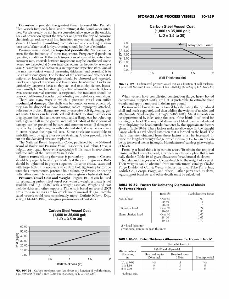
When vessels have complicated construction (large, heavy boltedconnections, support skirts, etc.), it is preferable to estimate theirweight and apply a unit cost in dollars per pound.
Pressure-vessel weights are obtained by calculating the cylindricalshell and heads separately and then adding the weights of nozzles andattachments. Steel weighs 7817 kg/m3 (488 lb/ft3). Metal in heads canbe approximated by calculating the area of the blank (disk) used forforming the head. The required diameter of blank can be calculatedby multiplying the head outside diameter by the approximate factorsgiven in Table 10-62. These factors make no allowance for the straightflange which is a cylindrical extension that is formed on the head. Theblank diameter obtained from these factors must be increased bytwice the length of straight flange, which is usually 11⁄2 to 2 in but canbe up to several inches in length. Manufacturers’ catalogs give weightsof heads.
Forming a head thins it in certain areas. To obtain the requiredminimum thickness of a head, it is necessary to use a plate that is ini-tially thicker. Table 10-63 gives allowances for additional thickness.
Nozzles and flanges may add considerably to the weight of a vessel.Their weights can be obtained from manufacturers’ catalogs (TaylorForge Division of Gulf & Western Industries, Inc., Tube Turns Inc.,Ladish Co., Lenape Forge, and others). Other parts such as skirts,legs, support brackets, and other details must be calculated.
STORAGE AND PROCESS VESSELS 10-159
Corrosion is probably the greatest threat to vessel life. Partiallyfilled vessels frequently have severe pitting at the liquid-vapor inter-face. Vessels usually do not have a corrosion allowance on the outside.Lack of protection against the weather or against the drip of corrosivechemicals can reduce vessel life. Insulation may contain damaging sub-stances. Chlorides in insulating materials can cause cracking of stain-less steels. Water used for hydrotesting should be free of chlorides.
Pressure vessels should be inspected periodically. No rule can begiven for the frequency of these inspections. Frequency depends onoperating conditions. If the early inspections of a vessel indicate a lowcorrosion rate, intervals between inspections may be lengthened. Somevessels are inspected at 5-year intervals; others, as frequently as once ayear. Measurement of corrosion is an important inspection item. One ofthe most convenient ways of measuring thickness (and corrosion) is touse an ultrasonic gauge. The location of the corrosion and whether it isuniform or localized in deep pits should be observed and reported.Cracks, any type of distortion, and leaks should be observed. Cracks areparticularly dangerous because they can lead to sudden failure. Insula-tion is usually left in place during inspection of insulated vessels. If, how-ever, severe external corrosion is suspected, the insulation should beremoved. All forms of nondestructive testing are useful for examinations.
There are many ways in which a pressure vessel can suffermechanical damage. The shells can be dented or even punctured,they can be dropped or have hoisting cables improperly attached,bolts can be broken, flanges are bent by excessive bolt tightening, gas-ket contact faces can be scratched and dented, rotating paddles candrag against the shell and cause wear, and a flange can be bolted upwith a gasket half in the groove and half out. Most of these forms ofdamage can be prevented by care and common sense. If damage isrepaired by straightening, as with a dented shell, it may be necessaryto stress-relieve the repaired area. Some steels are susceptible toembrittlement by aging after severe straining. A safer procedure is tocut out the damaged area and replace it.
The National Board Inspection Code, published by the NationalBoard of Boiler and Pressure Vessel Inspectors, Columbus, Ohio, ishelpful. Any repair, however, is acceptable if it is made in accordancewith the rules of the Pressure Vessel Code.
Care in reassembling the vessel is particularly important. Gasketsshould be properly located, particularly if they are in grooves. Boltsshould be tightened in proper sequence. In some critical cases andwith large bolts, it is necessary to control bolt tightening by torquewrenches, micrometers, patented bolt-tightening devices, or heatingbolts. After assembly, vessels are sometimes given a hydrostatic test.
Pressure-Vessel Cost and Weight Figure 10-196 can be usedfor estimating carbon-steel vessel cost when a weight estimate is notavailable and Fig. 10-197 with a weight estimate. Weight and costinclude skirts and other supports. The cost is based on several 2005pressure-vessels. Costs are for vessels not of unusual design. Compli-cated vessels could cost considerably more. Guthrie [Chem. Eng.,76(6), 114–142 (1969)] also gives pressure-vessel cost data.
Carbon Steel Vessel Cost(1,000 to 35,000 gal;
L/D = 3.5 to 30)
0.00
10.00
20.00
30.00
40.00
50.00
60.00
0 0.5 1.5 2
Wall Thickness (in)
Co
st (
$/g
al)
1
FIG. 10-196 Carbon-steel pressure-vessel cost as a function of wall thickness.1 gal = 0.003875 cm3; 1 in = 0.0254 m. (Courtesy of E. S. Fox, Ltd.)
Carbon Steel Vessel Cost(1,000 to 35,000 gal;
L/D = 3.5 to 30)
0.001.002.003.004.005.006.007.00
0 0.5 1 21.5
Wall Thickness (in)
Co
st (
$/lb
)
Alloy Steel Point
FIG. 10-197 Carbon-steel pressure-vessel cost as a function of wall thickness. 1 gal = 0.003875 cm3; 1 in = 0.0254 m; 1 lb = 0.4536 kg. (Courtesy of E. S. Fox, Ltd.)
TABLE 10-62 Factors for Estimating Diameters of Blanks for Formed Heads
Ratio d/t Blank diameter factor
ASME head Over 50 1.0930–50 1.1120–30 1.15
Ellipsoidal head Over 20 1.2410–20 1.30
Hemispherical head Over 30 1.6018–30 1.6510–18 1.70
d = head diametert = nominal minimum head thickness
TABLE 10-63 Extra Thickness Allowances for Formed Heads*
Extra thickness, in
Minimum headASME and ellipsoidal
thickness, Head o.d. up to Head o.d. overin 150 in incl. 150 in Hemispherical
Up to 0.99 g f t1 to 1.99 f f r2 to 2.99 d d v
*Lukens, Inc.

This page intentionally left blank


![[PPT]Lipid Transport & Storage - qums.ac.ireprints.qums.ac.ir/302/1/Lipid Transport & Storage-86.ppt · Web viewLipid Transport and Storage * Lipid transport & storage * LIPIDS ARE](https://static.fdocuments.in/doc/165x107/5aa076f27f8b9a67178e435e/pptlipid-transport-storage-qumsac-transport-storage-86pptweb-viewlipid-transport.jpg)