Creating PDF Files from MicroStation DGN Files - tdot.tn.gov · PDF fileThese settings files...
29
TDOT CADD Support • James K. Polk Bldg. • 505 Deaderick Street, Suite 1300 • Nashville, TN 37243 • Tel: 615-741-4482 • Email: • Website: [email protected] http://www.tn.gov/tdot/section/chief-engineer-design-home Creating PDF Files from MicroStation DGN Files Introduction T.D.O.T. Design Division personnel have two methods available to them for producing PDF files from plan sheets in MicroStation. Both of these are described in this document. The recommended method is with InterPlot Organizer, which is used for batch plotting and generating PDF plan sets. They can also use MicroStation Print to produce individual sheet PDF files. Consultants that use MicroStation’s Print Organizer tool for batch plotting can use that section for guidance in producing PDF plan sets. A single PDF file should be created that contains all required sheets for all plan sets except for the final construction plans turn in. For final construction plans, each individual sheet is generated as a separate PDF file. They can then be combined in a PDF portfolio where they can each be digitally signed by the project engineer(s). PDF Sheet Sizes All Plan sheets in PDF files used for posting to FileNet must be set up at full size. Other PDF plans sheet submittals may be half size as stipulated in the T.D.O.T. Design Division Guidelines. This document contains a section at the end describing the correct way to print from PDF files to avoid scaling errors. It shows document and paper sizes as well as how to print from either full or half size to generate any required prints you may need. PDF Plan Sets from InterPlot Organizer 1. Open InterPlot Organizer and create a plot set. The next several pages illustrate the set-up of sheets in InterPlot Organizer. They vary by type and when your plans were originally set up. Once you have your sheets set up in InterPlot Organizer you scan skip to page 8 and step 2. For plan sheets created after January 2006 that utilize the MicroStation V8 sheet borders: Create a plot set using settings files, PdfEnglishFul.set for regular plan sheets or PdfEnglishXSFul.set for cross section sheets. These settings files utilize a smaller plot shape in the MicroStation V8 sheet border that is drawn with color 253. This special plot shape for PDF generation was set up to stop data from being clipped from the right edge of the sheets when plotted from the PDF file. The resulting PDF document
Transcript of Creating PDF Files from MicroStation DGN Files - tdot.tn.gov · PDF fileThese settings files...
TDOT CADD Support • James K. Polk Bldg. • 505 Deaderick Street, Suite 1300 • Nashville, TN 37243 • Tel: 615-741-4482 • Email: • Website: [email protected] http://www.tn.gov/tdot/section/chief-engineer-design-home
Creating PDF Files from MicroStation DGN Files Introduction T.D.O.T. Design Division personnel have two methods available to them for producing PDF files from plan sheets in MicroStation. Both of these are described in this document. The recommended method is with InterPlot Organizer, which is used for batch plotting and generating PDF plan sets. They can also use MicroStation Print to produce individual sheet PDF files. Consultants that use MicroStation’s Print Organizer tool for batch plotting can use that section for guidance in producing PDF plan sets. A single PDF file should be created that contains all required sheets for all plan sets except for the final construction plans turn in. For final construction plans, each individual sheet is generated as a separate PDF file. They can then be combined in a PDF portfolio where they can each be digitally signed by the project engineer(s).
PDF Sheet Sizes All Plan sheets in PDF files used for posting to FileNet must be set up at full size. Other PDF plans sheet submittals may be half size as stipulated in the T.D.O.T. Design Division Guidelines. This document contains a section at the end describing the correct way to print from PDF files to avoid scaling errors. It shows document and paper sizes as well as how to print from either full or half size to generate any required prints you may need.
PDF Plan Sets from InterPlot Organizer
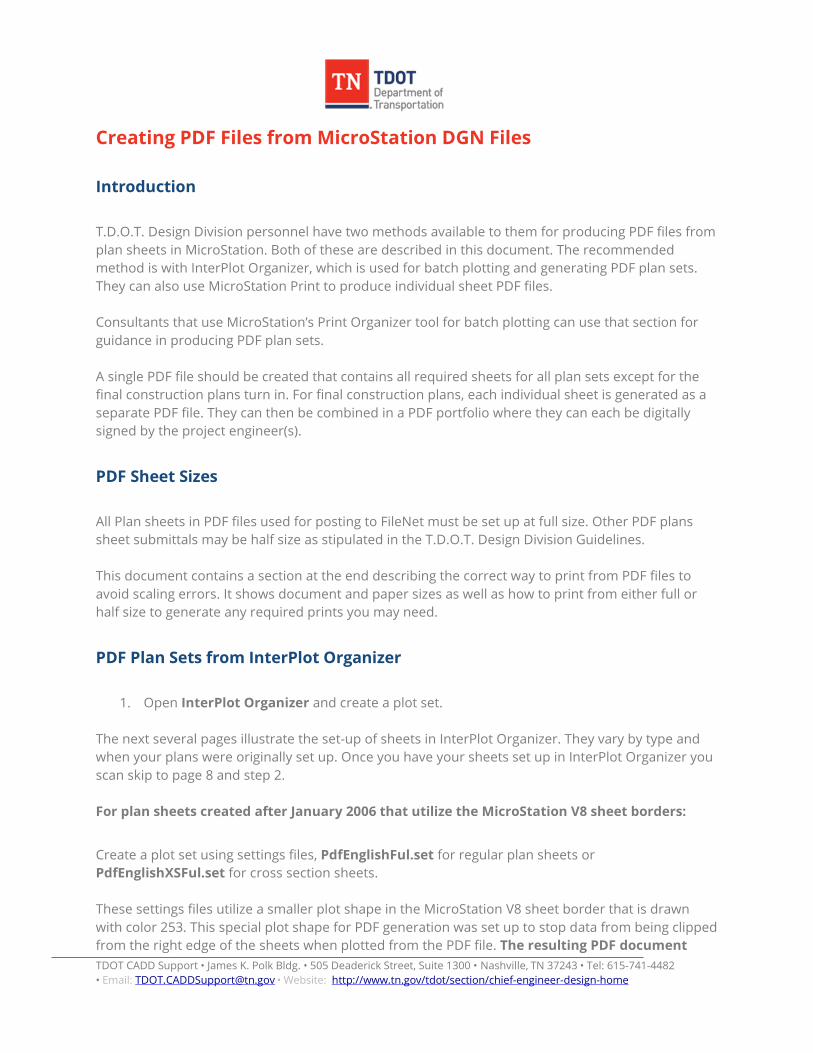
1. Open InterPlot Organizer and create a plot set. The next several pages illustrate the set-up of sheets in InterPlot Organizer. They vary by type and when your plans were originally set up. Once you have your sheets set up in InterPlot Organizer you scan skip to page 8 and step 2. For plan sheets created after January 2006 that utilize the MicroStation V8 sheet borders:
Create a plot set using settings files, PdfEnglishFul.set for regular plan sheets or PdfEnglishXSFul.set for cross section sheets. These settings files utilize a smaller plot shape in the MicroStation V8 sheet border that is drawn with color 253. This special plot shape for PDF generation was set up to stop data from being clipped from the right edge of the sheets when plotted from the PDF file. The resulting PDF document

TDOT CADD Support • James K. Polk Bldg. • 505 Deaderick Street, Suite 1300 • Nashville, TN 37243 • Tel: 615-741-4482 • Email: • Website: [email protected] http://www.tn.gov/tdot/section/chief-engineer-design-home
sheet size will be smaller than the normal printed sheet size so that it will fall within standard printer margins. Document Sheet Sizes Regular Full Size: 33.185” X 21” Cross Section Full Size: 32.85” X 21.25” Regular Plan Sheets (Full Size)
TDOT CADD Support • James K. Polk Bldg. • 505 Deaderick Street, Suite 1300 • Nashville, TN 37243 • Tel: 615-741-4482 • Email: • Website: [email protected] http://www.tn.gov/tdot/section/chief-engineer-design-home
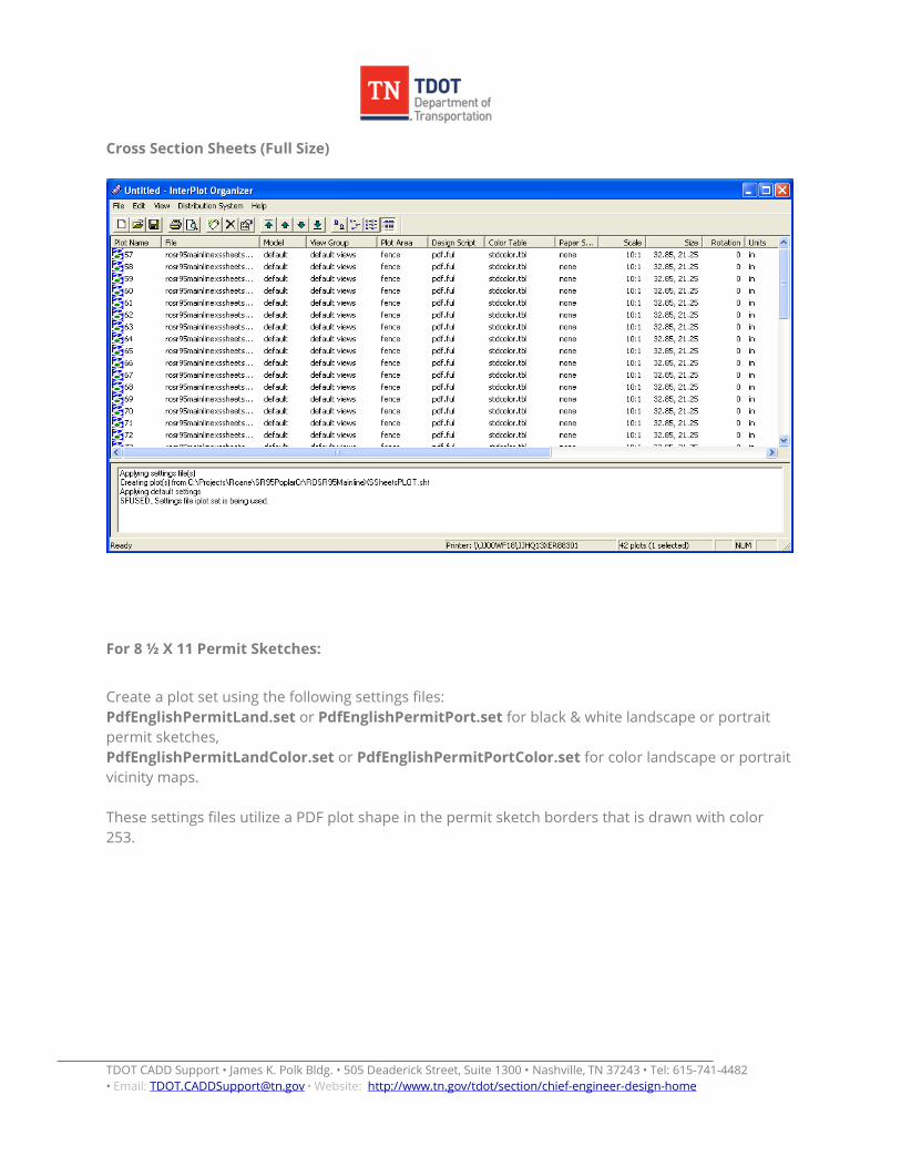
Cross Section Sheets (Full Size)
For 8 ½ X 11 Permit Sketches:
Create a plot set using the following settings files: PdfEnglishPermitLand.set or PdfEnglishPermitPort.set for black & white landscape or portrait permit sketches, PdfEnglishPermitLandColor.set or PdfEnglishPermitPortColor.set for color landscape or portrait vicinity maps. These settings files utilize a PDF plot shape in the permit sketch borders that is drawn with color 253.
TDOT CADD Support • James K. Polk Bldg. • 505 Deaderick Street, Suite 1300 • Nashville, TN 37243 • Tel: 615-741-4482 • Email: • Website: [email protected] http://www.tn.gov/tdot/section/chief-engineer-design-home
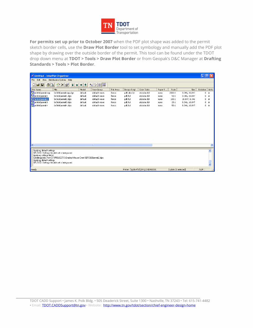
For permits set up prior to October 2007 when the PDF plot shape was added to the permit sketch border cells, use the Draw Plot Border tool to set symbology and manually add the PDF plot shape by drawing over the outside border of the permit. This tool can be found under the TDOT drop down menu at TDOT > Tools > Draw Plot Border or from Geopak’s D&C Manager at Drafting Standards > Tools > Plot Border.
TDOT CADD Support • James K. Polk Bldg. • 505 Deaderick Street, Suite 1300 • Nashville, TN 37243 • Tel: 615-741-4482 • Email: • Website: [email protected] http://www.tn.gov/tdot/section/chief-engineer-design-home
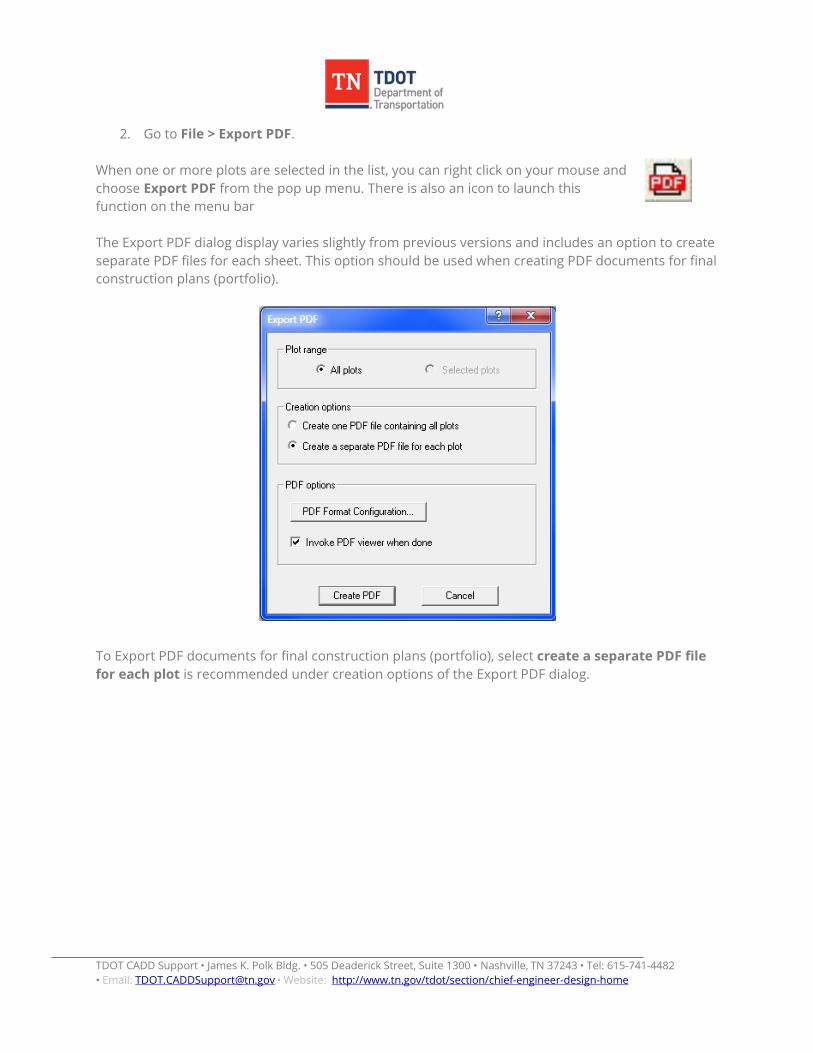
2. Go to File > Export PDF. When one or more plots are selected in the list, you can right click on your mouse and choose Export PDF from the pop up menu. There is also an icon to launch this function on the menu bar The Export PDF dialog display varies slightly from previous versions and includes an option to create separate PDF files for each sheet. This option should be used when creating PDF documents for final construction plans (portfolio).
To Export PDF documents for final construction plans (portfolio), select create a separate PDF file for each plot is recommended under creation options of the Export PDF dialog.
TDOT CADD Support • James K. Polk Bldg. • 505 Deaderick Street, Suite 1300 • Nashville, TN 37243 • Tel: 615-741-4482 • Email: • Website: [email protected] http://www.tn.gov/tdot/section/chief-engineer-design-home
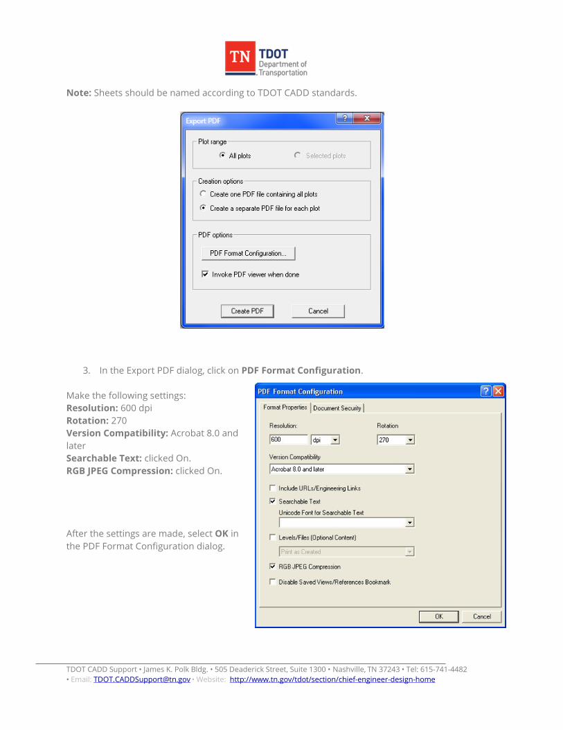
Note: Sheets should be named according to TDOT CADD standards.
3. In the Export PDF dialog, click on PDF Format Configuration. Make the following settings: Resolution: 600 dpi Rotation: 270 Version Compatibility: Acrobat 8.0 and later Searchable Text: clicked On. RGB JPEG Compression: clicked On. After the settings are made, select OK in the PDF Format Configuration dialog.
TDOT CADD Support • James K. Polk Bldg. • 505 Deaderick Street, Suite 1300 • Nashville, TN 37243 • Tel: 615-741-4482 • Email: • Website: [email protected] http://www.tn.gov/tdot/section/chief-engineer-design-home
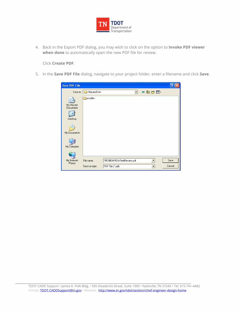
4. Back in the Export PDF dialog, you may wish to click on the option to Invoke PDF viewer
when done to automatically open the new PDF file for review. Click Create PDF.
5. In the Save PDF File dialog, navigate to your project folder, enter a filename and click Save.
TDOT CADD Support • James K. Polk Bldg. • 505 Deaderick Street, Suite 1300 • Nashville, TN 37243 • Tel: 615-741-4482 • Email: • Website: [email protected] http://www.tn.gov/tdot/section/chief-engineer-design-home
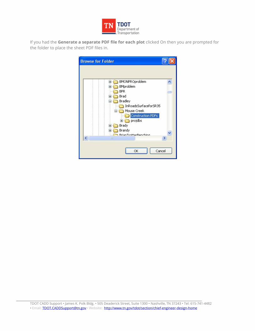
If you had the Generate a separate PDF file for each plot clicked On then you are prompted for the folder to place the sheet PDF files in.
TDOT CADD Support • James K. Polk Bldg. • 505 Deaderick Street, Suite 1300 • Nashville, TN 37243 • Tel: 615-741-4482 • Email: • Website: [email protected] http://www.tn.gov/tdot/section/chief-engineer-design-home
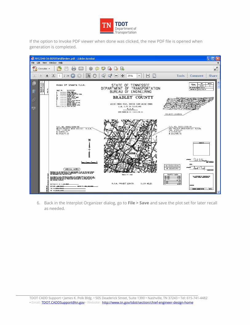
If the option to Invoke PDF viewer when done was clicked, the new PDF file is opened when generation is completed.
6. Back in the Interplot Organizer dialog, go to File > Save and save the plot set for later recall as needed.
TDOT CADD Support • James K. Polk Bldg. • 505 Deaderick Street, Suite 1300 • Nashville, TN 37243 • Tel: 615-741-4482 • Email: • Website: [email protected] http://www.tn.gov/tdot/section/chief-engineer-design-home
Creating PDF Portfolios for Final Construction Plans In the previous example, we created a plan set of all of the sheets. For final construction plans, each sheet must be a separate PDF. The previous steps can be used to create individual sheet PDF files as well. These individual PDF files are later combined in a portfolio so that each can be digitally signed by the engineer. For full documentation on creating PDF portfolios and digitally signing plans refer to documentation file Digital Signature Certification Workflow.pdf . Missing Data in Adobe Acrobat 9 In some instances and especially with PDF files created from scanned images, some sheets may not show when viewed in Adobe Acrobat version 9. You will often get the error prompt, “Insufficient data” when attempting to view the sheet. To correct this problem, simply re-generate the PDF document with version 9. Open the document in Adobe Acrobat version 9 and click the Print option. In the Print dialog, choose the printer, CutePDF Writer, make settings as needed to maintain the paper size and then click OK. After entering a name for the new PDF file, it is created using version 9 which will make the missing sheets visible in the new document.
TDOT CADD Support • James K. Polk Bldg. • 505 Deaderick Street, Suite 1300 • Nashville, TN 37243 • Tel: 615-741-4482 • Email: • Website: [email protected] http://www.tn.gov/tdot/section/chief-engineer-design-home
Creating PDF files using MicroStation Print
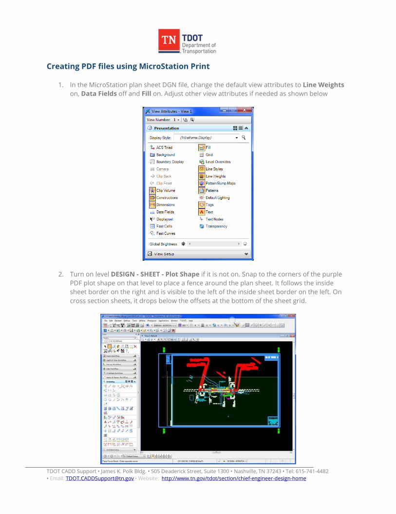
1. In the MicroStation plan sheet DGN file, change the default view attributes to Line Weights on, Data Fields off and Fill on. Adjust other view attributes if needed as shown below
2. Turn on level DESIGN - SHEET - Plot Shape if it is not on. Snap to the corners of the purple PDF plot shape on that level to place a fence around the plan sheet. It follows the inside sheet border on the right and is visible to the left of the inside sheet border on the left. On cross section sheets, it drops below the offsets at the bottom of the sheet grid.

TDOT CADD Support • James K. Polk Bldg. • 505 Deaderick Street, Suite 1300 • Nashville, TN 37243 • Tel: 615-741-4482 • Email: • Website: [email protected] http://www.tn.gov/tdot/section/chief-engineer-design-home
Warning: Do not use the plot snap points on the sheet border to set up the fence. These are set up for plotting to plotters that have the margins set at 0, not for PDF production.
3. MicroStation Print uses the current view attributes to set up the plot parameters. Turn off levels DESIGN - SHEET - Plot Shape and DESIGN - SCRATCH - User 1.
4. Open MicroStation Print. Go to File > Print or click the printer icon on the Standard tool
strip.
or from the TDOT Design Division tool strip, Plotting tool box
5. Attach the desired Bentley driver. In the MicroStation Print dialog go to File > Select Bentley Driver or click the browse icon next to the Bentley driver option on the dialog. Use plot configuration files Tdotpdfful.pltcfg, Tdotpdffulc.pltcfg (full size color) or Tdotpdfhaf.pltcfg to create PDF files. Using the full size plot driver, the Paper Size will default to PDF Regular Full (33.185 X 21) for regular plan sheets. Other paper options include PDF XS Full and PDF Permit Full.
TDOT CADD Support • James K. Polk Bldg. • 505 Deaderick Street, Suite 1300 • Nashville, TN 37243 • Tel: 615-741-4482 • Email: • Website: [email protected] http://www.tn.gov/tdot/section/chief-engineer-design-home
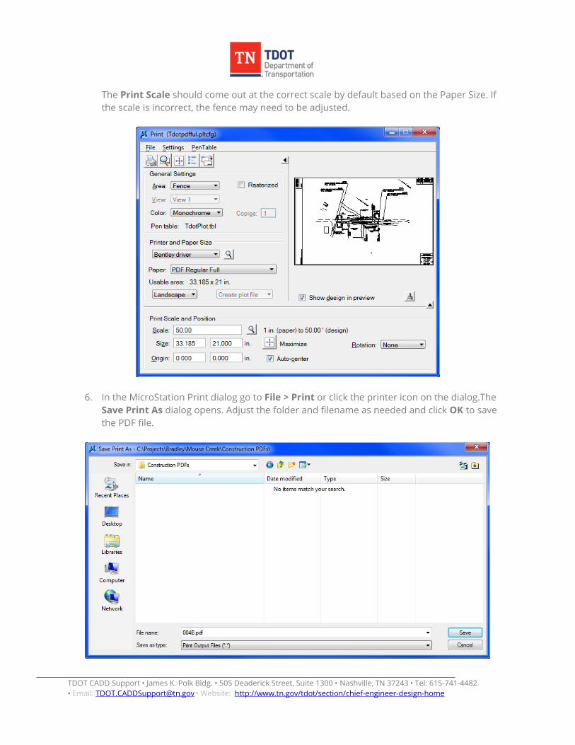
The Print Scale should come out at the correct scale by default based on the Paper Size. If the scale is incorrect, the fence may need to be adjusted.
6. In the MicroStation Print dialog go to File > Print or click the printer icon on the dialog.The Save Print As dialog opens. Adjust the folder and filename as needed and click OK to save the PDF file.
TDOT CADD Support • James K. Polk Bldg. • 505 Deaderick Street, Suite 1300 • Nashville, TN 37243 • Tel: 615-741-4482 • Email: • Website: [email protected] http://www.tn.gov/tdot/section/chief-engineer-design-home
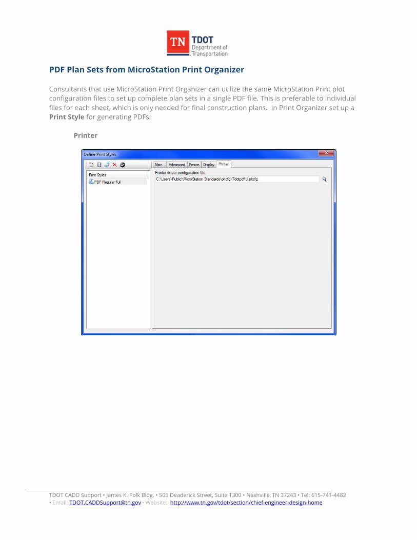
PDF Plan Sets from MicroStation Print Organizer Consultants that use MicroStation Print Organizer can utilize the same MicroStation Print plot configuration files to set up complete plan sets in a single PDF file. This is preferable to individual files for each sheet, which is only needed for final construction plans. In Print Organizer set up a Print Style for generating PDFs:
Printer
TDOT CADD Support • James K. Polk Bldg. • 505 Deaderick Street, Suite 1300 • Nashville, TN 37243 • Tel: 615-741-4482 • Email: • Website: [email protected] http://www.tn.gov/tdot/section/chief-engineer-design-home
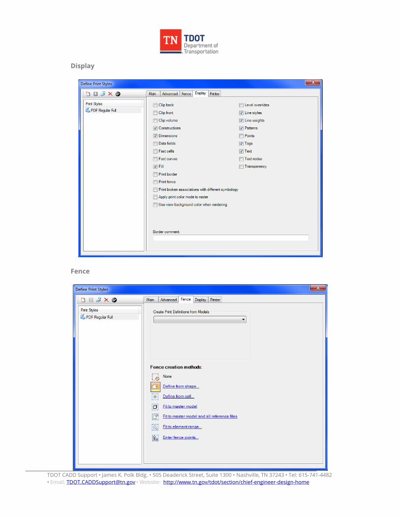
Display
Fence
TDOT CADD Support • James K. Polk Bldg. • 505 Deaderick Street, Suite 1300 • Nashville, TN 37243 • Tel: 615-741-4482 • Email: • Website: [email protected] http://www.tn.gov/tdot/section/chief-engineer-design-home
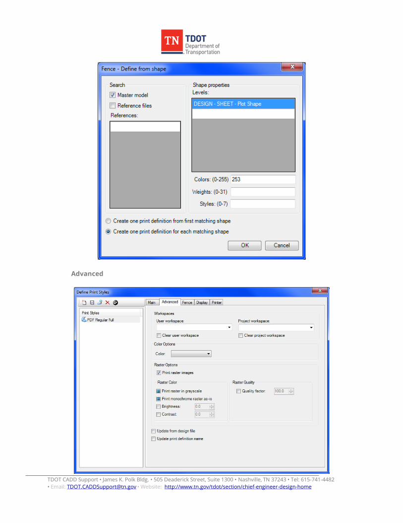
Advanced
TDOT CADD Support • James K. Polk Bldg. • 505 Deaderick Street, Suite 1300 • Nashville, TN 37243 • Tel: 615-741-4482 • Email: • Website: [email protected] http://www.tn.gov/tdot/section/chief-engineer-design-home
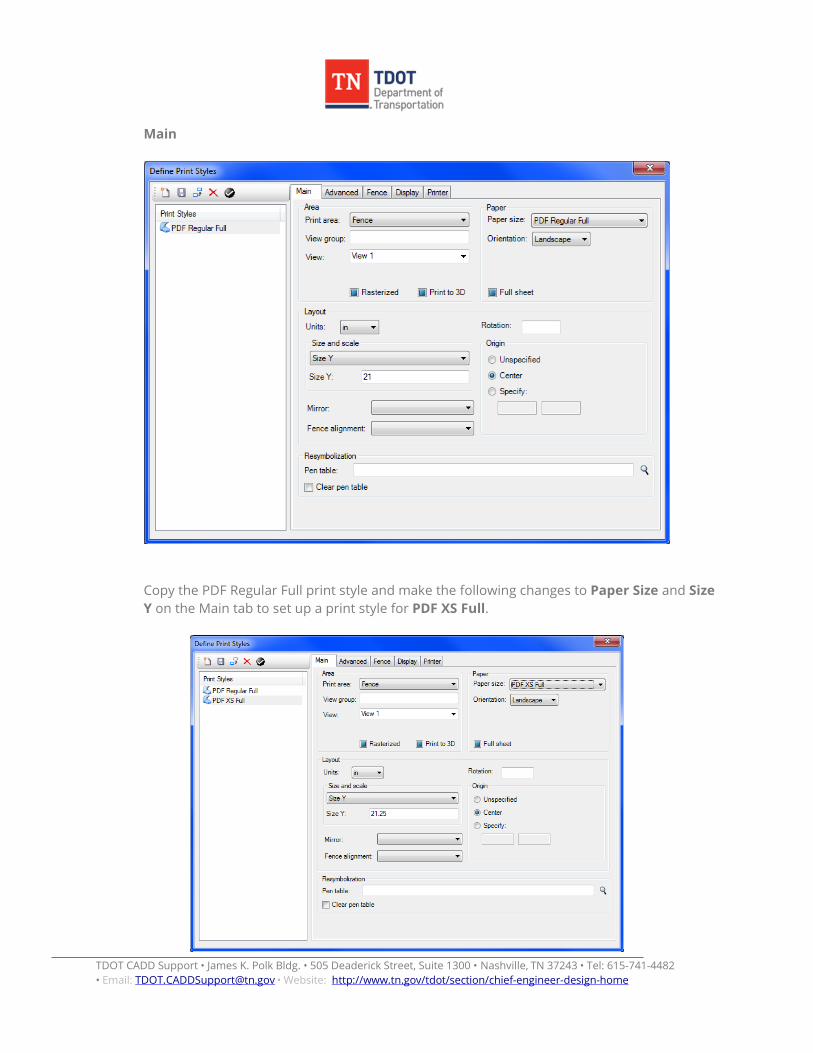
Main
Copy the PDF Regular Full print style and make the following changes to Paper Size and Size Y on the Main tab to set up a print style for PDF XS Full.
TDOT CADD Support • James K. Polk Bldg. • 505 Deaderick Street, Suite 1300 • Nashville, TN 37243 • Tel: 615-741-4482 • Email: • Website: [email protected] http://www.tn.gov/tdot/section/chief-engineer-design-home
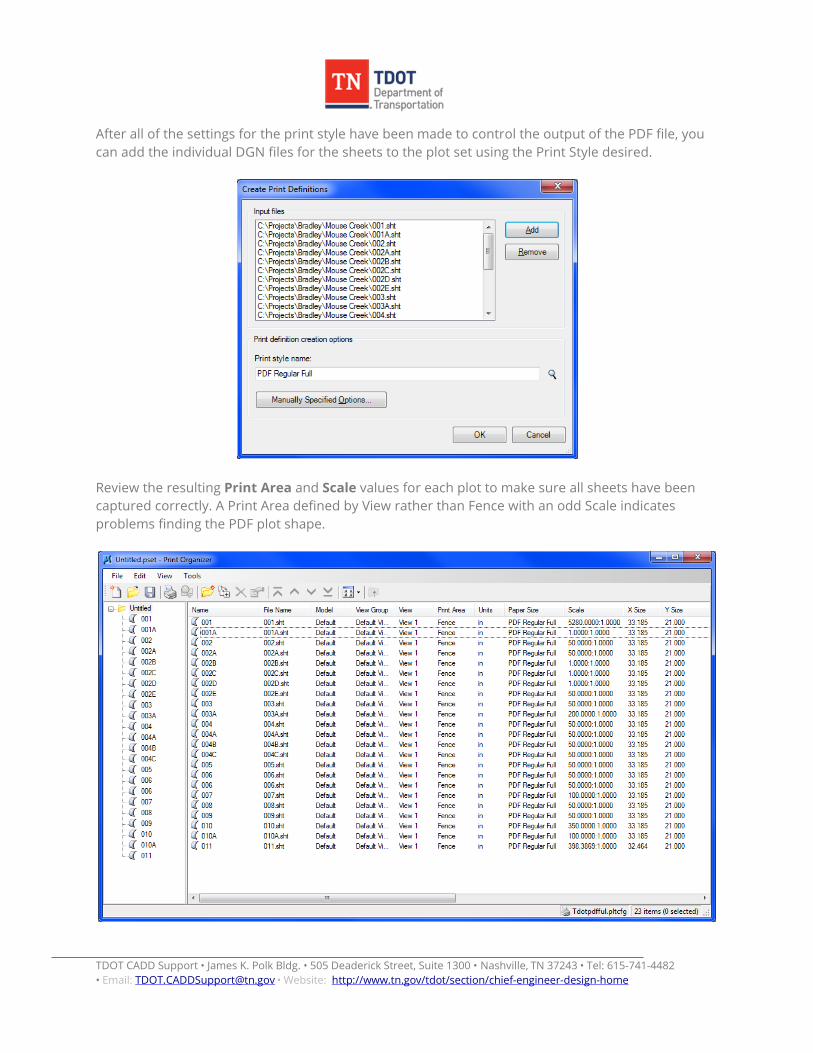
After all of the settings for the print style have been made to control the output of the PDF file, you can add the individual DGN files for the sheets to the plot set using the Print Style desired.
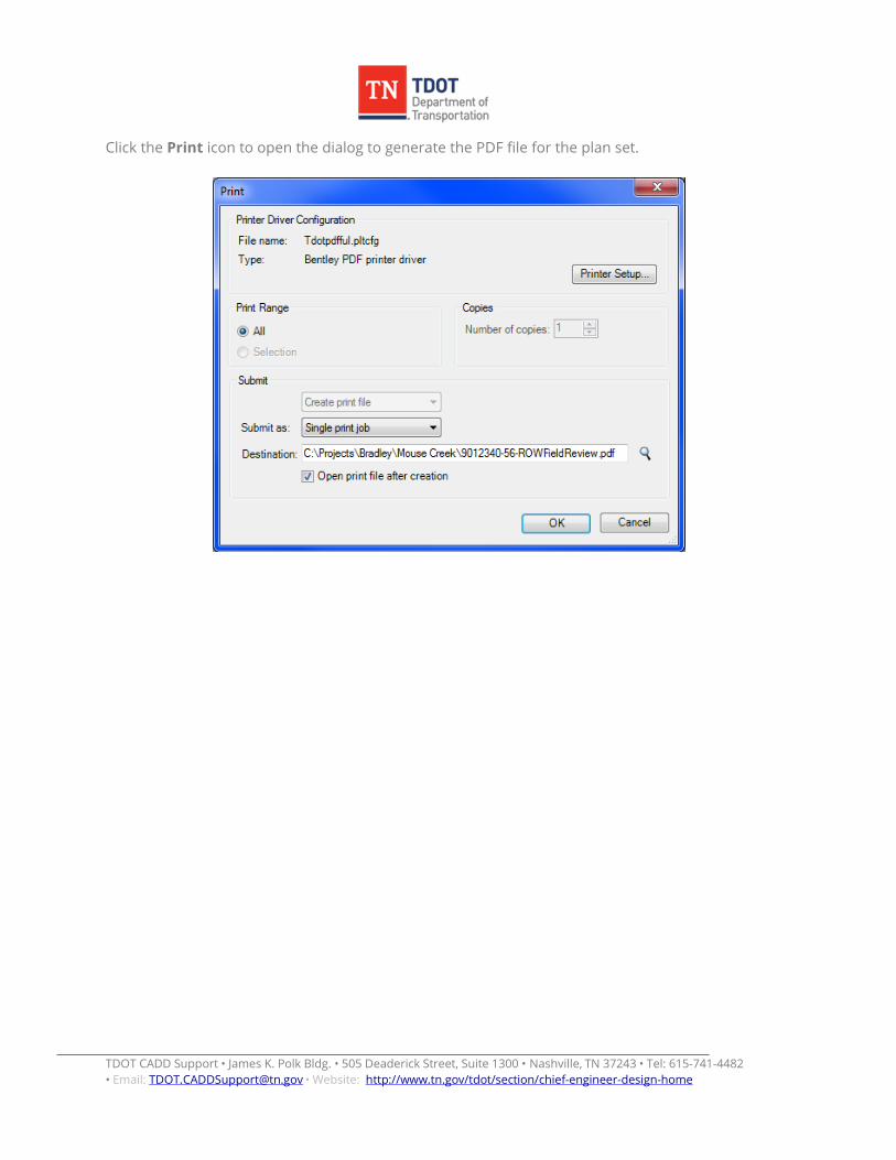
Review the resulting Print Area and Scale values for each plot to make sure all sheets have been captured correctly. A Print Area defined by View rather than Fence with an odd Scale indicates problems finding the PDF plot shape.
TDOT CADD Support • James K. Polk Bldg. • 505 Deaderick Street, Suite 1300 • Nashville, TN 37243 • Tel: 615-741-4482 • Email: • Website: [email protected] http://www.tn.gov/tdot/section/chief-engineer-design-home
Click the Print icon to open the dialog to generate the PDF file for the plan set.
TDOT CADD Support • James K. Polk Bldg. • 505 Deaderick Street, Suite 1300 • Nashville, TN 37243 • Tel: 615-741-4482 • Email: • Website: [email protected] http://www.tn.gov/tdot/section/chief-engineer-design-home
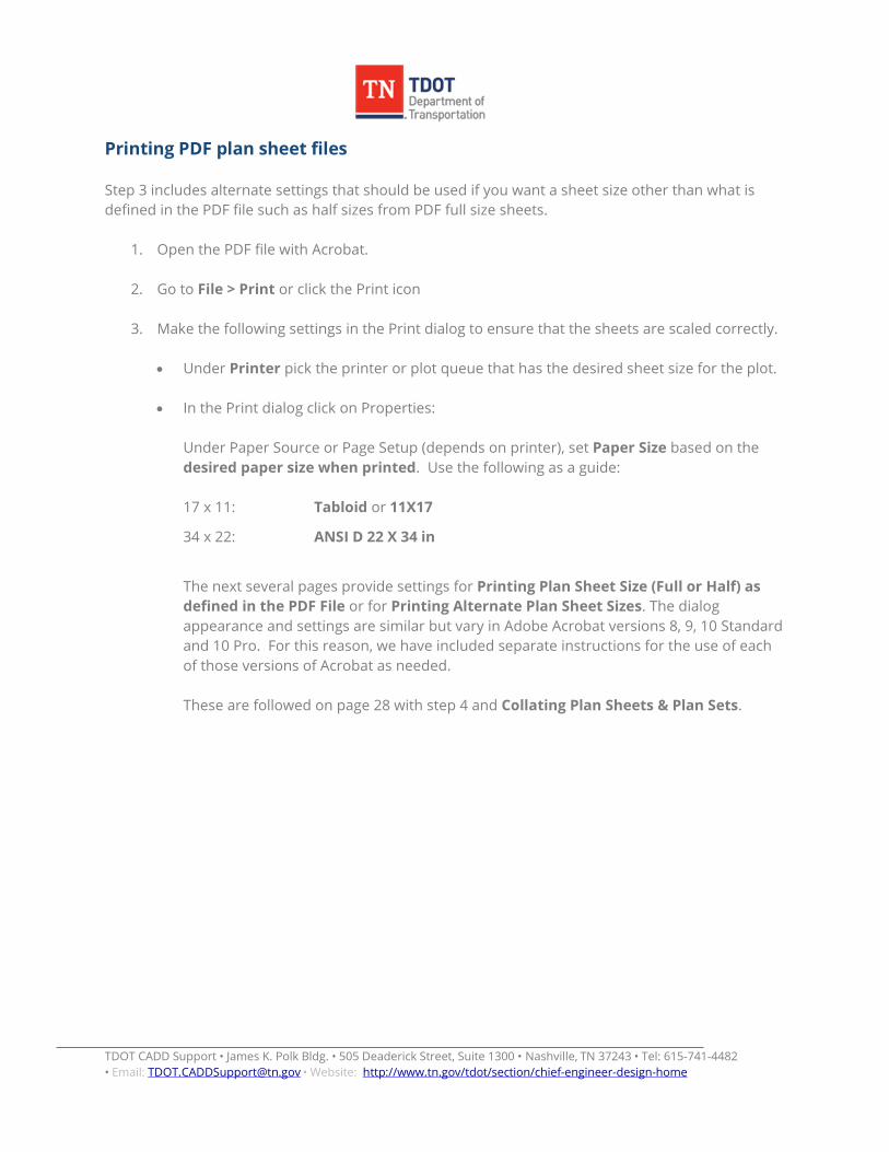
Printing PDF plan sheet files Step 3 includes alternate settings that should be used if you want a sheet size other than what is defined in the PDF file such as half sizes from PDF full size sheets.
1. Open the PDF file with Acrobat.
2. Go to File > Print or click the Print icon
3. Make the following settings in the Print dialog to ensure that the sheets are scaled correctly.
• Under Printer pick the printer or plot queue that has the desired sheet size for the plot.
• In the Print dialog click on Properties:
Under Paper Source or Page Setup (depends on printer), set Paper Size based on the desired paper size when printed. Use the following as a guide: 17 x 11: Tabloid or 11X17
34 x 22: ANSI D 22 X 34 in
The next several pages provide settings for Printing Plan Sheet Size (Full or Half) as defined in the PDF File or for Printing Alternate Plan Sheet Sizes. The dialog appearance and settings are similar but vary in Adobe Acrobat versions 8, 9, 10 Standard and 10 Pro. For this reason, we have included separate instructions for the use of each of those versions of Acrobat as needed.
These are followed on page 28 with step 4 and Collating Plan Sheets & Plan Sets.
TDOT CADD Support • James K. Polk Bldg. • 505 Deaderick Street, Suite 1300 • Nashville, TN 37243 • Tel: 615-741-4482 • Email: • Website: [email protected] http://www.tn.gov/tdot/section/chief-engineer-design-home
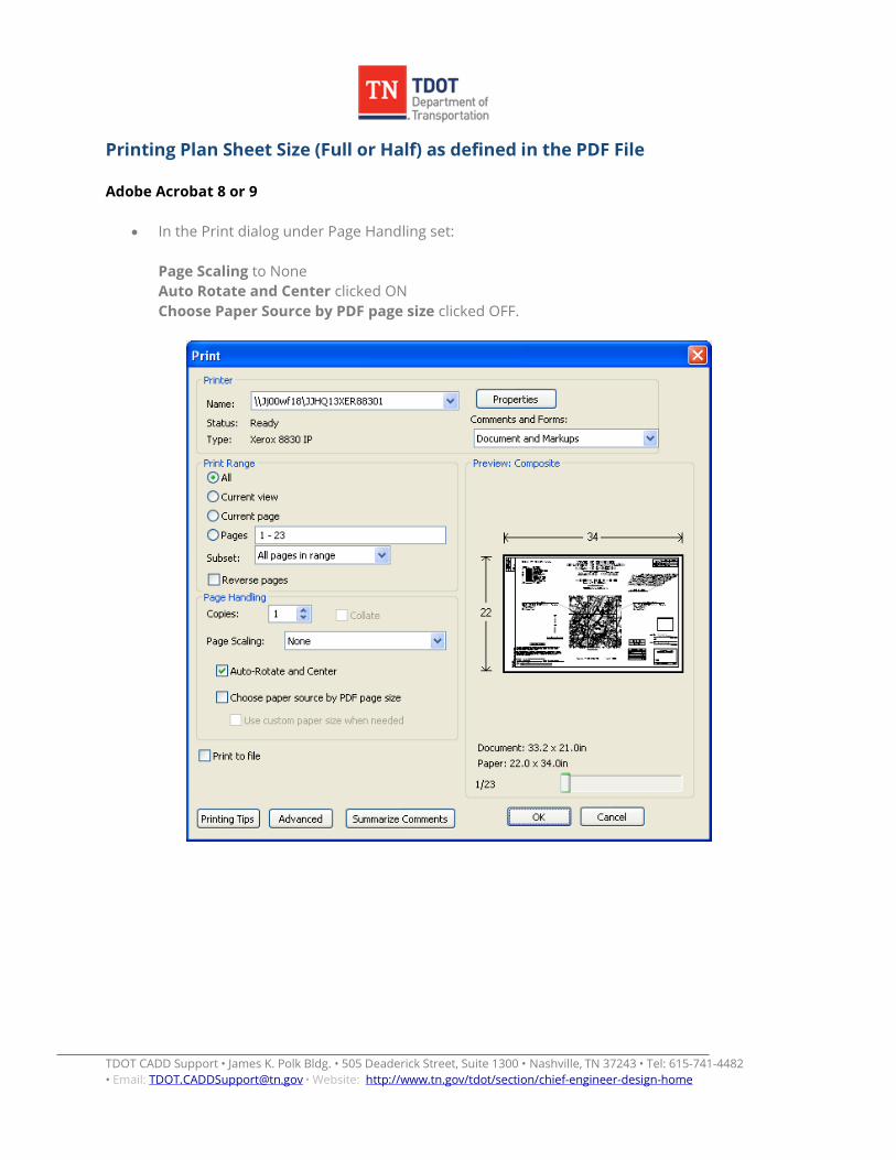
Printing Plan Sheet Size (Full or Half) as defined in the PDF File Adobe Acrobat 8 or 9
• In the Print dialog under Page Handling set:
Page Scaling to None Auto Rotate and Center clicked ON Choose Paper Source by PDF page size clicked OFF.
TDOT CADD Support • James K. Polk Bldg. • 505 Deaderick Street, Suite 1300 • Nashville, TN 37243 • Tel: 615-741-4482 • Email: • Website: [email protected] http://www.tn.gov/tdot/section/chief-engineer-design-home
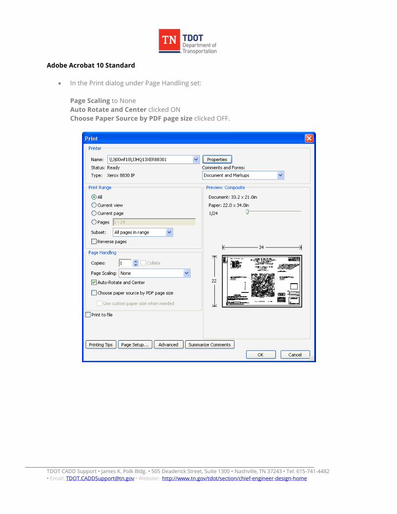
Adobe Acrobat 10 Standard
• In the Print dialog under Page Handling set:
Page Scaling to None Auto Rotate and Center clicked ON Choose Paper Source by PDF page size clicked OFF.

TDOT CADD Support • James K. Polk Bldg. • 505 Deaderick Street, Suite 1300 • Nashville, TN 37243 • Tel: 615-741-4482 • Email: • Website: [email protected] http://www.tn.gov/tdot/section/chief-engineer-design-home
Adobe Acrobat 10 Pro
• In the Print dialog under Page Sizing & Handling set:
Size ON Size Options to Actual Size Choose Paper Source by PDF page size clicked OFF. Orientation to Auto Portrait/Landscape
TDOT CADD Support • James K. Polk Bldg. • 505 Deaderick Street, Suite 1300 • Nashville, TN 37243 • Tel: 615-741-4482 • Email: • Website: [email protected] http://www.tn.gov/tdot/section/chief-engineer-design-home
Printing Alternate Plan Sheet Sizes Using the following settings specified for Adobe Acrobat 8 or 9, you can print half sizes at the correct scale from full size PDF files generated using the plot shape used to plot to plotters (Document dimension: 34 X 21.788 inches) but data will be clipped slightly on the right when printed on printers with standard margins. Adobe Acrobat 10 Standard or 10 Pro will not let you print half sizes at the correct scale from full size PDF files generated using the plot shape used to plot to plotters (Document dimension: 34 X 21.788 inches) when printed on printers with standard margins. They do not allow margin overlaps as previous versions of Acrobat did. You can use the Fit or Shrink options, which will yield an approximate half size but it will not be to the correct scale. The specifications shown below are for the current specified methods of PDF sheet generation using the special PDF plot shape that is reduced in size to correct the margin overlap problem when printing on printers with standard margins.
TDOT CADD Support • James K. Polk Bldg. • 505 Deaderick Street, Suite 1300 • Nashville, TN 37243 • Tel: 615-741-4482 • Email: • Website: [email protected] http://www.tn.gov/tdot/section/chief-engineer-design-home
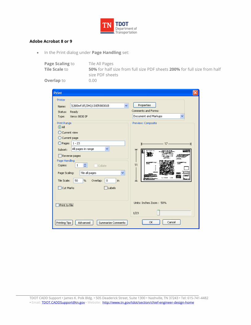
Adobe Acrobat 8 or 9
• In the Print dialog under Page Handling set:
Page Scaling to Tile All Pages Tile Scale to 50% for half size from full size PDF sheets 200% for full size from half
size PDF sheets Overlap to 0.00

TDOT CADD Support • James K. Polk Bldg. • 505 Deaderick Street, Suite 1300 • Nashville, TN 37243 • Tel: 615-741-4482 • Email: • Website: [email protected] http://www.tn.gov/tdot/section/chief-engineer-design-home
Adobe Acrobat 10 Standard
• In the Print dialog under Page Handling set:
Page Scaling to Tile All Pages Tile Scale to 50% for half size from full size PDF sheets 200% for full size from half
size PDF sheets Overlap to 0.00
TDOT CADD Support • James K. Polk Bldg. • 505 Deaderick Street, Suite 1300 • Nashville, TN 37243 • Tel: 615-741-4482 • Email: • Website: [email protected] http://www.tn.gov/tdot/section/chief-engineer-design-home
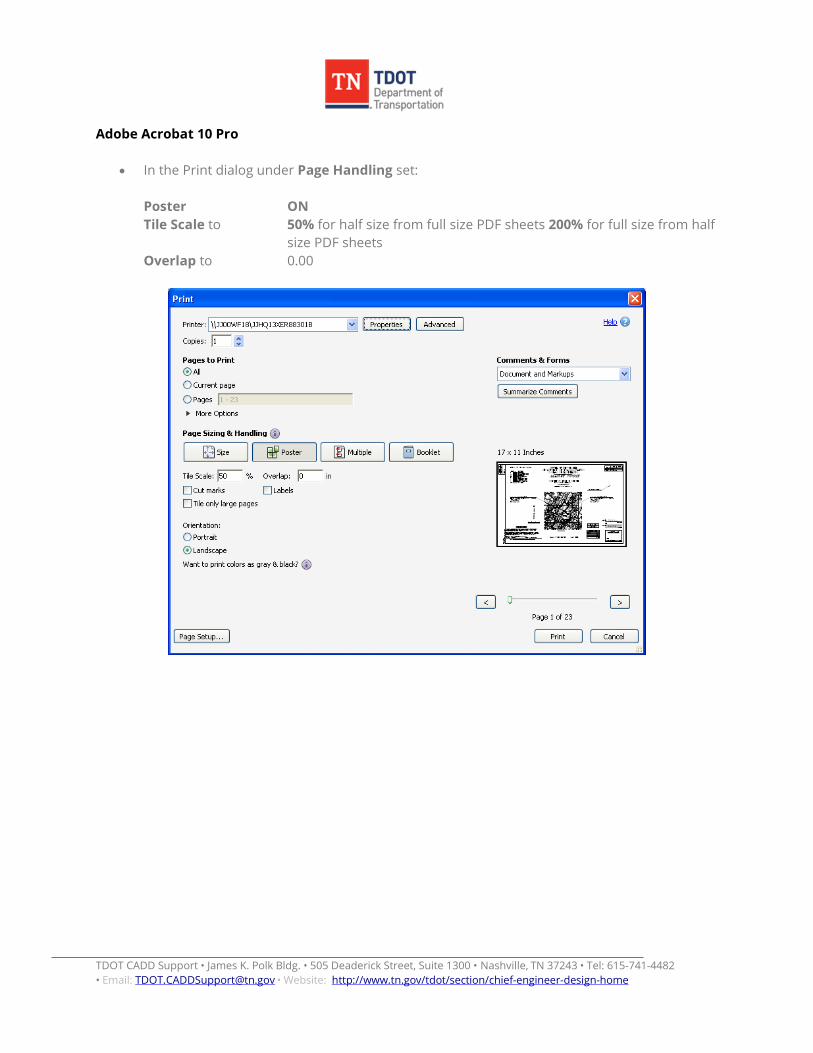
Adobe Acrobat 10 Pro
• In the Print dialog under Page Handling set:
Poster ON Tile Scale to 50% for half size from full size PDF sheets 200% for full size from half
size PDF sheets Overlap to 0.00
TDOT CADD Support • James K. Polk Bldg. • 505 Deaderick Street, Suite 1300 • Nashville, TN 37243 • Tel: 615-741-4482 • Email: • Website: [email protected] http://www.tn.gov/tdot/section/chief-engineer-design-home
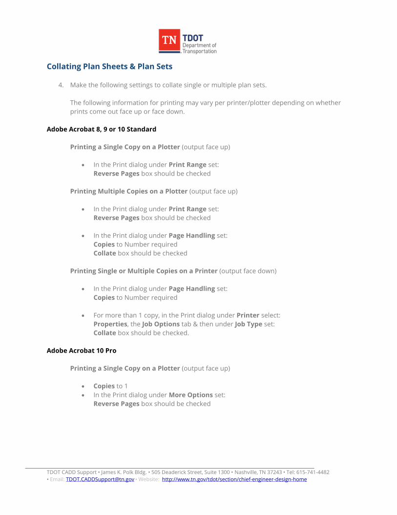
Collating Plan Sheets & Plan Sets
4. Make the following settings to collate single or multiple plan sets.
The following information for printing may vary per printer/plotter depending on whether prints come out face up or face down.
Adobe Acrobat 8, 9 or 10 Standard Printing a Single Copy on a Plotter (output face up)
• In the Print dialog under Print Range set: Reverse Pages box should be checked
Printing Multiple Copies on a Plotter (output face up)
• In the Print dialog under Print Range set: Reverse Pages box should be checked
• In the Print dialog under Page Handling set: Copies to Number required Collate box should be checked
Printing Single or Multiple Copies on a Printer (output face down)
• In the Print dialog under Page Handling set: Copies to Number required
• For more than 1 copy, in the Print dialog under Printer select: Properties, the Job Options tab & then under Job Type set: Collate box should be checked.
Adobe Acrobat 10 Pro
Printing a Single Copy on a Plotter (output face up)
• Copies to 1 • In the Print dialog under More Options set:
Reverse Pages box should be checked
TDOT CADD Support • James K. Polk Bldg. • 505 Deaderick Street, Suite 1300 • Nashville, TN 37243 • Tel: 615-741-4482 • Email: • Website: [email protected] http://www.tn.gov/tdot/section/chief-engineer-design-home
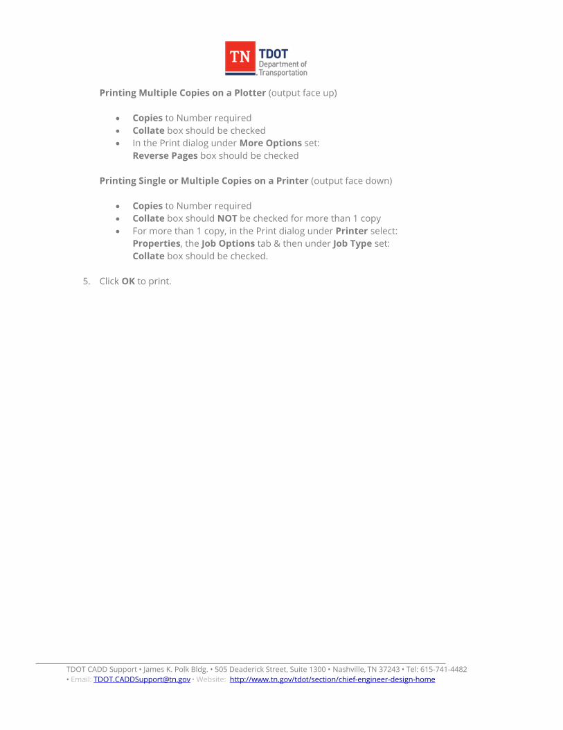
Printing Multiple Copies on a Plotter (output face up)
• Copies to Number required • Collate box should be checked • In the Print dialog under More Options set:
Reverse Pages box should be checked Printing Single or Multiple Copies on a Printer (output face down)
• Copies to Number required • Collate box should NOT be checked for more than 1 copy • For more than 1 copy, in the Print dialog under Printer select:
Properties, the Job Options tab & then under Job Type set: Collate box should be checked.
5. Click OK to print.