Passive Components: Capacitors & Resistors Topics: General ...
Upload
tobias-griffithCategory
view
224download
1
1
HVACR317 - Refrigeration
Start Components
2
Start Components
• Start components come in two types:– Capacitors– Start Relays
3
Back EMF
• Whenever you spin a magnet in a coil of wires you will create voltage.
• Back EMF is the excess voltage that is created in a motor. It is difficult to measure, as it is not in the same frequency as the line voltage being applied.
• Back EMF produced in coils will cause the current to decrease.

4
Start Relays
• The purpose of a start relay is to remove the start circuit of a single-phase compressor motor at 75% of the motor’s full rpm.
5
Start Relays
• Sequence of operation:– Thermostat closes• Current goes way up – this is Locked rotor
amps– Capacitor jolts start winding as it
discharges.• Motor starts turning.• Creates back EMF which creates resistance
and lowers amperage to FLA (Full load amps).– The back EMF which is created helps
remove the start winding.

6
Start Relays
• The start winding must be taken out electrically or it will burn out.– Start windings are made of thinner gauge wire
than run windings, and cannot handle the excessive current.
• The only purpose of a motor start winding is to get the rotor in the motor to start turning.

7
Start Relays
• There are four types of start relays to learn about: −Current Relay, Coil Type−Current Relay, Hot wire type−Current Relay, Solid State type−Voltage Relay, Potential Type

8
Current Coil Relay
• Current-sensitive relay that energizes on the locked rotor amps (LRA) of the motor.
• Locked rotor amps are much higher than the motor’s full load amperage (FLA).
• The LRA is the amperage a motor draws when it is powered, but not turning. – This is about 6 times higher than the full
rating.
9
Current Coil Relay
• The FLA is the amperage of the motor when it is fully operational or running at 100% of its rated rpm.– If the FLA is too high:• Condenser may be dirty.• Refrigerant may be overcharged.• Compressor may be going bad.
10
Current Coil Relay
• The current coil relay will de-energize when the motor reaches its FLA rating (a second or two after the motor start).
• There are two configurations of the current coil relay:–Without a start capacitor–With a start capacitor

11
Current Coil Relay – No Start Capacitor
S
RL1
L2/N
L M
S
Key:
L = LineM = Main (or Run)S = Start
12
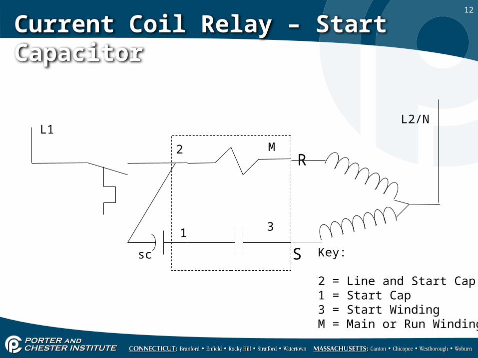
Current Coil Relay – Start Capacitor
S
R
L1L2/N
2 M
3
Key:
2 = Line and Start Cap1 = Start Cap3 = Start WindingM = Main or Run Winding
1
sc
13
Current Coil Characteristics
• Most types mount directly on the compressor motor terminals.
• The relay can only be mounted right side up – gravity matters and the contacts are not spring loaded.– Look for “TOP” on the relay
14
Current Coil Characteristics
• Most often used on motors that are 1 hp or less.
• Has one set of normally open contacts.
• The coil of the relay always gets connected in series with the run winding of the compressor.
15
Current Coil Sequence of Operation• When the thermostat closes, the LRA
of the compressor will create enough magnetism through the relay to push up (close) the normally open contacts.
• The coil resistance is close to 0 ohms, which allows all the voltage to be applied to the compressor run winding even though they are two loads in series.
16
Current Coil Sequence of Operation • Next, as the rotor starts to turn,
back EMF starts building up in the motor windings.
• The generated back EMF drops the current draw down to FLA, and the reduction in current de-energizes the relay coil.
• The motor will run on the run winding only.

17
Current Coil Troubleshooting
• Best method for troubleshooting is to use the ohm meter.–With the relay right side up, the coil
should read 0 ohms and the contact should read infinity.
–With the relay upside down, the coil should be 0 ohms and the contact should read 0 ohms.
• When finding a replacement part, use the model number of the compressor.

18
Current Coil Troubleshooting
• The most common symptom of a bad relay is a hum/click sort of noise. The first time you hear it, you will know it.

19
Hot Wire Relay
• Older design very seldom used anymore.• Replaced by the current coil or solid state
type.• Also used on fractional horsepower motors
(less than 1 hp)
20
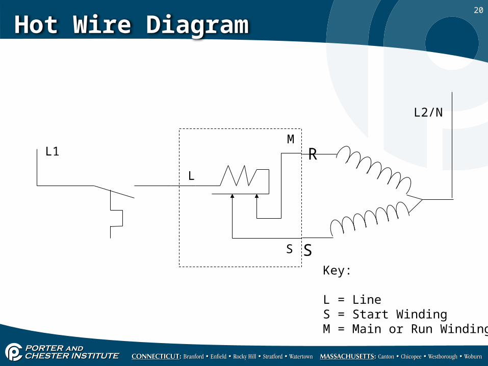
Hot Wire Diagram
S
RL1
L2/N
M
Key:
L = LineS = Start WindingM = Main or Run Winding
L
S
21
Hot Wire Relay Characteristics
• Contains two sets of normally closed contacts.
• Operates thermally by current flow that creates heat through a small wire.
• The heat will warp a bi-metal contact (the S) which opens it.
• Breaks path to start winding.

22
Hot Wire Relay Characteristics
• The relay has its own overload protection.
• If the motor gets stuck in LRA the second contact (M) will heat up and open as well.
• Does not need a motor overload switch.

23
Hot Wire Relay Troubleshooting
• Any problems with starting? Replace it with a solid state relay.
24
Current Relay – Solid State
• Solid State means it is a non-mechanical device (no moving parts).
• This relay is also known as a thermistor type relay or a PTC relay.
• A Thermistor is a device that changes its resistance value as current passes through it.

25
Thermistor Diagram
26
Solid State Relay
• PTC stands for Positive Temperature Co-efficient. The higher the temperature of the device, the less efficiently current can pass through the device.
• Solid state relays are also used mostly on fractional (under 1 hp) motors.
27
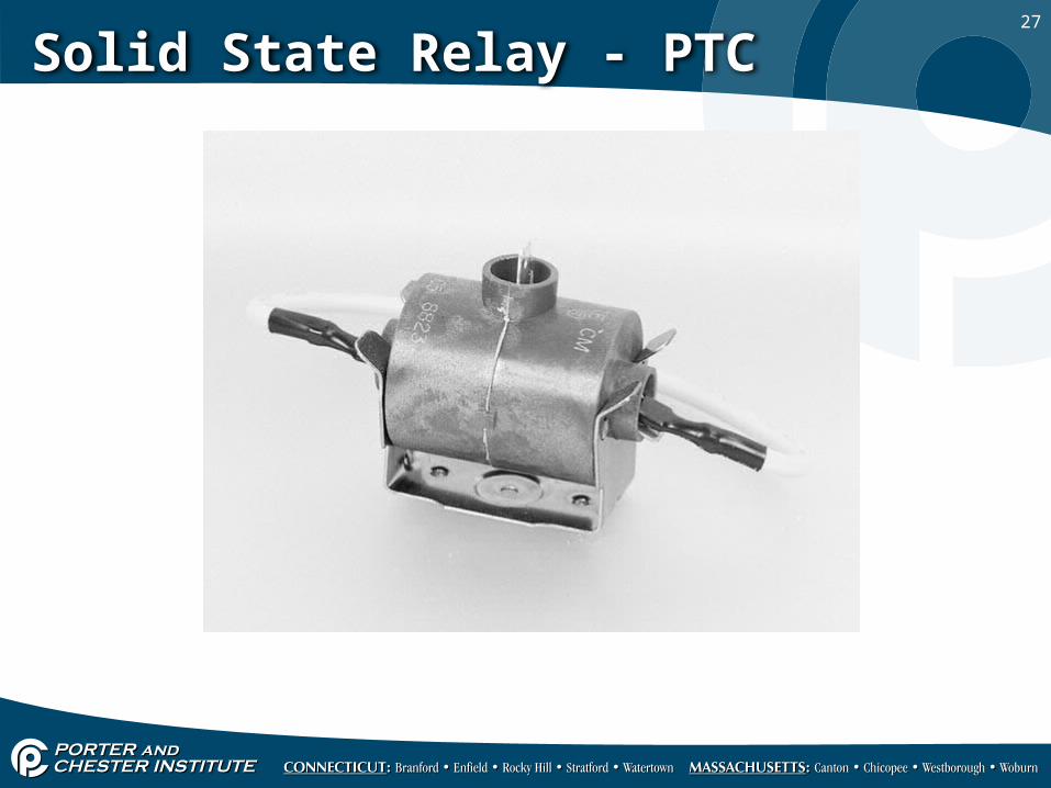
Solid State Relay - PTC

28
Solid State Relay Characteristics
• The relay is made of a conductive ceramic.
• The ceramic disk is about the size of a dime and has a very low resistance (about 3 to 5 ohms) when at room temperature.
• When the current passes through the disk, the resistance rapidly increases to a value of about 80K ohms.

29
Solid State Relay Diagram
C
S
R
3-5 Ohm Rating

30
Solid State Sequence of Operations• The thermostat closes• The motor achieves LRA.• The current heats the relay.• At about 80K ohm of resistance, the
start winding is effectively removed from the circuit, with all power flowing through the run winding.
31
Types of Solid State Relays
• There are three types of solid state relays:– Plug in type– Two wire type– Five wire type
32
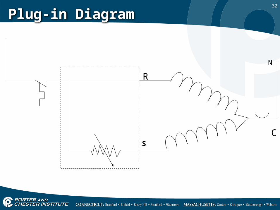
Plug-in Diagram
N
C
R
S

33
Two Wire Diagram
N
C
R
S
Thermistor is wired in series with start winding

34
Five Wire Diagram
S
R
C
N
LL
S
R
C
35
Solid State Relays
• The two and the five wire types are field replacement types. They can be used to replace the plug-in, the current coil, and the hot wire.
• Make sure you check hp (horsepower) ratings before using replacement.
36
Solid State Relay Troubleshooting• The best method to use for
troubleshooting is an ohm meter.–When at room temperature, look for three
to five ohms.– If the solid state relay is warm, look for a
high resistance.

37
Potential Relay
• An electromagnetic type relay.– Uses voltage to operate in the same
principle as a control relay.
• Potential relays ALWAYS use a start capacitor.
• Most of the time there will also be a run capacitor.

38
Potential Relay
A Potential relay, a run capacitor and a start capacitor.

39
Potential Relay Schematic
1 2 5

40
Potential Relay Characteristics
• Contains one set of normally closed contacts.
• Coil has a resistance of 6000 to 12000 ohms.– Between pins 1 and 5 you should have 6-
12K ohms.– Between pins 1 and 2 you should have 0
ohms.• The coil voltage is generated by the back
EMF across the compressor start winding.
41
Potential Relay Characteristics
• It is used on compressor motors from ½ to 10 hp.
• Potential relays and start capacitors provide a very high starting torque.
• Anything that needs power beyond this point will require a three-phase compressor.

42
Potential Relay Wiring
1 2 5
Terminal 1 Start CapacitorTerminal 2 Connects to start windingTerminal 3 Connects to compressor common, or motor overload
Sometimes the relay will come equipped with a terminal 3, 4, and 6 – these are dummy terminals used for junction points only.
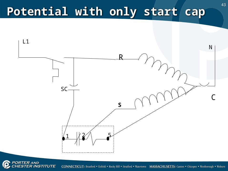
43
Potential with only start cap
L1N
C
R
S
1 2 5
SC
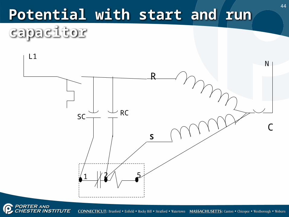
44
Potential with start and run capacitor
L1N
C
R
S
1 2 5
SC RC
45
Potential Relay Troubleshooting
• Use an ohm meter to detect problems.− Test the contacts between 1 and 2; this should
be a 0 ohm reading.− Test the coil between 2 and 5; this should be a
very high resistance.− Complete test 1 to 5; should be a very high
resistance as the coil and the contacts are getting checked together.
46
General Troubleshooting
• Sometimes on very high microfarad capacitors, there is a bleed resistor across the terminals. This is designed to purge voltage out of the capacitor. Do not trust it - always bleed the capacitor yourself.
• If the start winding is open the Motor Overload will trip.
47
General Troubleshooting
• If the run winding is open the motor will not start, but the overload (MOL) will not trip.

48
Hard Start Kits
• A hard-start kit is a combination of a start capacitor and relay.– Refrigeration hard-start kits contain a
solid state relay and do not have a microfarad (mfd) rating. They cannot exceed ½ hp.
– Air conditioning hard-start kits contain a potential relay and can range from ½ to 5 horsepower.


![Cicuit Components 1 G6 - CIRCUIT COMPONENTS [3 exam question - 3 groups] G6AResistors; capacitors; inductors G6BRectifiers; solid state diodes and transistors;](https://static.fdocuments.in/doc/165x107/56649dc35503460f94ab5cc4/cicuit-components-1-g6-circuit-components-3-exam-question-3-groups-g6aresistors.jpg)