^1 HARDWARE REFERENCE MANUAL PMAC2 Ethernet Ultralite.pdf · Turbo PMAC2 Eth Ultralite Manual...
28
^1 HARDWARE REFERENCE MANUAL ^2 Turbo PMAC2 Eth Ultralite ^3 Programmable Multi-Axis Controller ^4 4xx-603862-1xx ^5 February 15, 2010 Single Source Machine Control Power // Flexibility // Ease of Use 21314 Lassen Street Chatsworth, CA 91311 // Tel. (818) 998-2095 Fax. (818) 998-7807 // www.deltatau.com
Transcript of ^1 HARDWARE REFERENCE MANUAL PMAC2 Ethernet Ultralite.pdf · Turbo PMAC2 Eth Ultralite Manual...

^1 HARDWARE REFERENCE MANUAL
^2 Turbo PMAC2 Eth Ultralite
^3 Programmable Multi-Axis Controller
^4 4xx-603862-1xx
^5 February 15, 2010
Single Source Machine Control Power // Flexibility // Ease of Use 21314 Lassen Street Chatsworth, CA 91311 // Tel. (818) 998-2095 Fax. (818) 998-7807 // www.deltatau.com
Copyright Information © 2010 Delta Tau Data Systems, Inc. All rights reserved. This document is furnished for the customers of Delta Tau Data Systems, Inc. Other uses are unauthorized without written permission of Delta Tau Data Systems, Inc. Information contained in this manual may be updated from time-to-time due to product improvements, etc., and may not conform in every respect to former issues. To report errors or inconsistencies, call or email: Delta Tau Data Systems, Inc. Technical Support Phone: (818) 717-5656 Fax: (818) 998-7807 Email: [email protected] Website: http://www.deltatau.com Operating Conditions All Delta Tau Data Systems, Inc. motion controller products, accessories, and amplifiers contain static sensitive components that can be damaged by incorrect handling. When installing or handling Delta Tau Data Systems, Inc. products, avoid contact with highly insulated materials. Only qualified personnel should be allowed to handle this equipment. In the case of industrial applications, we expect our products to be protected from hazardous or conductive materials and/or environments that could cause harm to the controller by damaging components or causing electrical shorts. When our products are used in an industrial environment, install them into an industrial electrical cabinet or industrial PC to protect them from excessive or corrosive moisture, abnormal ambient temperatures, and conductive materials. If Delta Tau Data Systems, Inc. products are exposed to hazardous or conductive materials and/or environments, we cannot guarantee their operation

REVISION HISTORY
REV. DESCRIPTION DATE CHG APPVD
1 NEW MANUAL CREATION 06/27/08 CP S. SATTARI
2 REVISED PART NUMBER DEFINITION, P. 4 UPDATED MECHANICAL DRAWING, P. 6 UPDATED SYSTEM WIRING, P. 7 UPDATED J5 & J8 PINOUTS/CONNECTORS, P.12,14ADDED J10 INFORMATION, P. 18
01/28/09 CP S.SATTARI
3 CORRECTION IN J5 PIN-OUT TABLE UPDATED WIRING FOR HANDWHEEL PORT IMAGE
02/15/10 CP S.SATTARI
Turbo PMAC2 Eth Ultralite Manual
TABLE OF CONTENTS i
Table of Contents
INTRODUCTION ........................................................................................................................................ 1
Overview .................................................................................................................................................... 1
Configuration.............................................................................................................................................. 1 Base Version ........................................................................................................................................... 1
Part Number Definition .............................................................................................................................. 4
HARDWARE SETUP.................................................................................................................................. 5
Receiving and Unpacking........................................................................................................................... 5
Mounting .................................................................................................................................................... 5
Mechanical Drawing................................................................................................................................... 6
System Wiring ............................................................................................................................................ 7
Pushbutton Switches................................................................................................................................... 8 FW LOAD switch .................................................................................................................................... 8 RE-INIT switch........................................................................................................................................ 8
Connections ................................................................................................................................................ 8 USB Connection, J1 ................................................................................................................................ 8 Ethernet / Modbus Connection, J2.......................................................................................................... 9 Fieldbus Setup Connector, J3 ............................................................................................................... 10 Fieldbus Connection, J4 (Fieldbus option required) ............................................................................ 10 General Purpose I/O Connection, J5.................................................................................................... 12 Auxiliary Connector, J8 ........................................................................................................................ 14 24 VDC Power Supply Input, J9 ........................................................................................................... 17 MACRO Connector ............................................................................................................................... 18 Thumbwheel Multiplexer Port (JTHW Port), J10 ................................................................................. 18
SOFTWARE SETUP ................................................................................................................................. 21
Host Communications .............................................................................................................................. 21 Pewin32PRO2 Communication Setup................................................................................................... 21
Turbo PMAC2 Eth Ultralite Manual
INTRODUCTION 1
Introduction
Overview
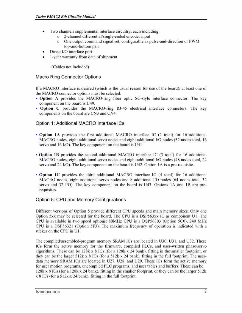
The Turbo PMAC2 Eth Ultralite is a member of the Turbo PMAC family of boards optimized for interface to the system through the MACRO ring and therefore does not contain on-board axis interface circuitry (which is what makes it Ultralite). It can command up to 32 axes through the MACRO ring. The Turbo PMAC2 Eth Ultralite is a stand-alone unit which can be communicated with via RS-232, USB or Ethernet connections. However, the dual-ported RAM can only be accessed over USB or Ethernet for high speed communication with the controller. This controller is also capable of Fieldbus communications when the appropriate option is ordered. The pin out of this connection is dependent on which Fieldbus protocol is being utilized and it supports the following protocols:
• ProfiBus Master Opt-G1 • ProfiBus Slave Opt-G2 • DeviceNet Master Opt-G3 • DeviceNet Slave Opt-G4 • CANopen Master Opt-G5 • CANopen Slave Opt-G6 • CC-Link Slave Opt-GB
The protocol is dependent upon which hardware and therefore option is selected. The hardware cannot be programmed for an alternate protocol including master/slave. Additional I/O points are available through a Thumbwheel port which supports multiplexed I/O devices such as ACC-34AA or Opto-22 digital I/O modules.
Configuration
Base Version The base version of the Turbo PMAC2 Eth Ultralite provides:
• 80 MHz DSP56303 CPU • 128k x 24 SRAM compiled/assembled program memory • 128k x 24 SRAM user data memory • 1M x 8 flash memory for user backup & firmware • 32k x 16 bank of dual-ported RAM • Latest released firmware version • RS-232 serial interface, USB 2.0 & Ethernet Communication • (No on-board axis interface circuitry)
Turbo PMAC2 Eth Ultralite Manual
INTRODUCTION 2
• Two channels supplemental interface circuitry, each including: o 2-channel differential/single-ended encoder input o One output command signal set, configurable as pulse-and-direction or PWM
top-and-bottom pair • Direct I/O interface port • 1-year warranty from date of shipment
(Cables not included)
Macro Ring Connector Options If a MACRO interface is desired (which is the usual reason for use of the board), at least one of the MACRO connector options must be selected. • Option A provides the MACRO-ring fiber optic SC-style interface connector. The key
component on the board is U49. • Option C provides the MACRO-ring RJ-45 electrical interface connectors. The key
components on the board are CN3 and CN4.
Option 1: Additional MACRO Interface ICs • Option 1A provides the first additional MACRO interface IC (2 total) for 16 additional
MACRO nodes, eight additional servo nodes and eight additional I/O nodes (32 nodes total, 16 servo and 16 I/O). The key component on the board is U41.
• Option 1B provides the second additional MACRO interface IC (3 total) for 16 additional
MACRO nodes, eight additional servo nodes and eight additional I/O nodes (48 nodes total, 24 servo and 24 I/O). The key component on the board is U42. Option 1A is a pre-requisite.
• Option 1C provides the third additional MACRO interface IC (4 total) for 16 additional
MACRO nodes, eight additional servo nodes and 8 additional I/O nodes (64 nodes total, 32 servo and 32 I/O). The key component on the board is U43. Options 1A and 1B are pre-requisites.
Option 5: CPU and Memory Configurations Different versions of Option 5 provide different CPU speeds and main memory sizes. Only one Option 5xx may be selected for the board. The CPU is a DSP563xx IC as component U1. The CPU is available in two speed options: 80MHz CPU is a DSP56303 (Option 5C0), 240 MHz CPU is a DSP56321 (Option 5F3). The maximum frequency of operation is indicated with a sticker on the CPU in U1. The compiled/assembled-program memory SRAM ICs are located in U30, U31, and U32. These ICs form the active memory for the firmware, compiled PLCs, and user-written phase/servo algorithms. These can be 128k x 8 ICs (for a 128k x 24 bank), fitting in the smaller footprint, or they can be the larger 512k x 8 ICs (for a 512k x 24 bank), fitting in the full footprint. The user-data memory SRAM ICs are located in U27, U28, and U29. These ICs form the active memory for user motion programs, uncompiled PLC programs, and user tables and buffers. These can be 128k x 8 ICs (for a 128k x 24 bank), fitting in the smaller footprint, or they can be the larger 512k x 8 ICs (for a 512k x 24 bank), fitting in the full footprint.

Turbo PMAC2 Eth Ultralite Manual
INTRODUCTION 3
The flash memory IC is located in U26. This IC forms the non-volatile memory for the board’s firmware, the user setup variables, and for user programs, tables, and buffers. It can be 1M x 8, 2M x 8, or 4M x 8 in capacity.
• Option 5C0: Default CPU speed and memory configuration: 80MHz DSP56303 CPU (8Kx24 internal memory), 128Kx24 SRAM compiled/assembled program memory, 128Kx24 SRAM user data memory, 1Mx8 flash memory.
• Option 5C3: Default CPU speed and memory configuration: 80MHz DSP56303 CPU
(8Kx24 internal memory), expanded 512Kx24 SRAM compiled/assembled program memory, expanded 512Kx24 SRAM user data memory, 4Mx8 flash memory.
• Option 5F3: 240MHz DSP56321 CPU (192Kx24 internal memory), expanded 512Kx24
SRAM compiled/assembled program memory, expanded 512Kx24 SRAM user data memory, 4Mx8 flash memory.
Option 10: Firmware Version Specification Normally the Turbo PMAC2 Eth Ultralite is provided with the newest released firmware version. The response to the VERSION query command shows which firmware revision is presently installed. Option 10 provides for a user-specified firmware version.
Option 12: Analog-to-Digital and Digital-to-Analog Converters Option 12 permits the installation of 2 channels of on-board analog-to-digital converters and one channel of on-board digital-to-analog converter. The analog inputs are not optically isolated, and each can have a +/- 10V input range, or a +/-5V input range if differential signal is used, individually selectable with a 12-bit resolution. The analog output is a 12-bit DAC have +/-10V output range.
Turbo PMAC2 Eth Ultralite Manual
INTRODUCTION 4
Part Number Definition
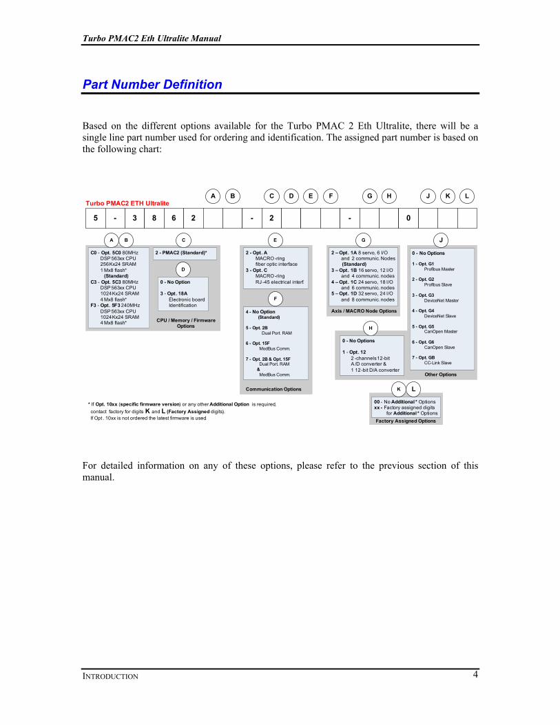
Based on the different options available for the Turbo PMAC 2 Eth Ultralite, there will be a single line part number used for ordering and identification. The assigned part number is based on the following chart:
5 - 3 8 6 2 - 2 - 0
Turbo PMAC2 ETH Ultralite
Communication Options
C F H
A
F
H
2 - Opt. A MACRO -ring fiber optic interface3 - Opt. C MACRO -ring RJ -45 electrical interf.
Axis / MACRO Node Options
2 – Opt. 1A 8 servo, 6 I/O and 2 communic. Nodes
(Standard)3 – Opt. 1B 16 servo, 12 I/O and 4 communic. nodes4 – Opt. 1C 24 servo, 18 I/O and 6 communic. nodes5 – Opt. 1D 32 servo, 24 I/O and 8 communic. nodes
H
G
C0 - Opt. 5C0 80MHz DSP 563xx CPU 256Kx24 SRAM 1 Mx8 flash*
(Standard)C3 - Opt. 5C3 80MHz DSP 563xx CPU 1024Kx24 SRAM 4 Mx8 flash*F3 - Opt. 5F3 240MHz DSP 563xx CPU 1024Kx24 SRAM 4 Mx8 flash* CPU / Memory / Firmware
Options
C
2 - PMAC2 (Standard)*
D
D
0 - No Option
3 - Opt. 18A Electronic board Identification
A B
B
LK
00 - No Additional * Optionsxx - Factory assigned digits
for Additional * Options
K L
Factory Assigned Options
* If Opt. 10xx (specific firmware version) or any other Additional Option is required, contact factory for digits K and L (Factory Assigned digits). If Opt . 10xx is not ordered the latest firmware is used.
4 - No Option(Standard)
5 - Opt. 2B Dual Port. RAM
6 - Opt. 15F ModBus Comm.
7 - Opt. 2B & Opt. 15F Dual Port. RAM
& ModBus Comm.
E J
E
G
0 - No Options
1 - Opt. G1 Profibus Master
2 - Opt. G2 Profibus Slave
3 - Opt. G3 DeviceNet Master
4 - Opt. G4 DeviceNet Slave
5 - Opt. G5 CanOpen Master
6 - Opt. G6 CanOpen Slave
7 - Opt. GB CC-Link Slave
J
0 - No Options
1 - Opt. 12 2 -channels 12-bit A /D converter & 1 12-bit D/A converter
Other Options
For detailed information on any of these options, please refer to the previous section of this manual.

Turbo PMAC2 Eth Ultralite Manual
HARDWARE SETUP 5
Hardware Setup
Receiving and Unpacking Delta Tau products are thoroughly tested at the factory and carefully packaged for shipment. When the Turbo PMAC2 Eth Ultralite is received, do the following immediately:
1. Inspect the condition of the shipping container and report any damage immediately to the commercial carrier that delivered the drive.
2. Remove the controller from the shipping container and remove all packing materials. Check all shipping material for connector kits, documentation, diskettes, CD ROM, or other small pieces of equipment. Be aware that some connector kits and other equipment pieces may be quite small and can be accidentally discarded if care is not used when unpacking the equipment. The container and packing materials may be retained for future shipment.
3. Verify that the part number of the drive received is the same as the part number listed on the purchase order.
4. Inspect the drive for external physical damage that may have been sustained during shipment and report any damage immediately to the commercial carrier that delivered the controller.
5. Electronic components in this controller are design-hardened to reduce static sensitivity. However, use proper procedures when handling the equipment.
6. If the controller is to be stored for several weeks before use, be sure that it is stored in a location that conforms to published storage humidity and temperature specifications stated in this manual.
Mounting The location of the control is important. Installation should be in an area that is protected from direct sunlight, corrosives, harmful gases or liquids, dust, metallic particles, and other contaminants. Exposure to these can reduce the operating life and degrade performance of the control. Several other factors should be evaluated carefully when selecting a location for installation:
• For effective cooling and maintenance, the control should be mounted on a smooth, non-flammable vertical surface.
• At least 3 inches (76mm) top and bottom clearance must be provided for airflow. At least 0.4 inches (10mm) clearance is required between controls (each side).
• Temperature, humidity and vibration specifications should also be taken in account. The Turbo PMAC2 Eth Ultralite can be mounted with a traditional 2-hole panel mount, one U shape/notch on the bottom and one pear shaped hole on top. The controller is mounted to a back panel. The back panel should be unpainted and electrically conductive to allow for reduced electrical noise interference. The back panel should be machined to accept the mounting bolt pattern of the drive. Make sure that all metal chips are cleaned up before the controller is mounted so there is no risk of getting metal chips inside the controller.

Turbo PMAC2 Eth Ultralite Manual
HARDWARE SETUP 6
The controller is mounted to the back panel with four M4 screws and internal-tooth lock washers. It is important that the teeth break through any anodization on the controllers’s mounting gears to provide a good electrically conductive path in as many places as possible. Mount the controller on the back panel so there is airflow at both the top and bottom areas of the controller (at least three inches).
Caution:
Units must be installed in an enclosure that meets the environmental IP rating of the end product (ventilation or cooling may be necessary to prevent enclosure ambient from exceeding 45° C [113° F]).
Mechanical Drawing The figures below show the mounting dimensions of the controller.

Turbo PMAC2 Eth Ultralite Manual
HARDWARE SETUP 7
System Wiring
12345678
91 01 11 21 31 41 5
1234567891 01 11 21 3
1 41 51 61 71 81 92 02 12 22 32 42 5
1
2
3
4
5
6
7
8
9
1 0
1 1
1 2
1 3
1 4
1 5
1 6
1 7
1 8
1 9
2 0
2 1
2 2
2 3
2 4
2 5
2 6
12
34
56
78
9
10
12
34
5
67
89
12345
6789
HandwheelDAC outputADC Input
Pulse and Direction
J8 AUXJ5 General I /OJ10 JTHW
MACRORJ45
OUT
IN
MACROFIBER
OUT
IN
ETHERNET
USB
FIELDBUSSETUP
FIELDBUS
RD
Y
RU
N
ER
R
STA
/MO
D
FIELDBUSINTERFACE
RS-232 FW L
OA
D
RE
-INIT
24VD
C
INP
UT
GN
D
+24
VDC
8 Sinking/Sourcing Digital Inputs4 Sourcing /Sinking Digital Outputs
Watchdog relay contacts1 Sinking/Sourcing Input
8 Inputs / 8 Outputs TTL Level
(typically used to create multiplexed I /O with accessory boards )
The Macro Connector will be used to form a ring between all the MACRO components of
the system .
For RJ -45 connector , standard CAT -5 or CAT -6 cables with standard RJ -45 connection can
be used to form the ring .
For FIBER option , fiber cable with SC - style connectors is used as communication medium
between the MACRO stations
Ethernet connection can be used either for communication between the unit and a PC as user interface or with MODBUS option it can
be configured as MODBUS MASTER or SLAVE for expanding the control solution .
USB connection can be used either for communication between the unit and a PC as
user interface .
FIELDBUS connector gets connected directly to the Hilscher module inside the unit and the
SyCon software for setting up the module
The FIELDBUS connector is the main connector between the Hilscher module and the optional FieldBus network . Please check the pin out configuration section carefully .
Serial Connection (RS-232 ) can be used to talk to the CPU directly. Since the parser on this port can be turned off , it can also be
used for communicating to the 3rd party devices over
RS- 232
By h
oldi
ng F
W L
OA
D m
icro
-sw
itch
whi
le
pow
er-u
p, y
ou c
an p
lace
the
card
in
Boo
tstr
ap m
ode
for l
oadi
ng fi
rmw
are
By h
oldi
ng R
E-I
NIT
mic
ro-s
witc
h w
hile
pow
er-
up, t
he
card
will
load
the
fact
ory
de
faul
t se
ttin
gs in
stea
d of
sa
ved
setti
ngs
on F
LAS
H
24VDC 0. 75 A continues
1. 8 A start up
Turbo PMAC2 Eth Ultralite Manual
HARDWARE SETUP 8
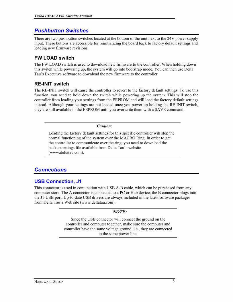
Pushbutton Switches There are two pushbutton switches located at the bottom of the unit next to the 24V power supply input. These buttons are accessible for reinitializing the board back to factory default settings and loading new firmware revisions.
FW LOAD switch The FW LOAD switch is used to download new firmware to the controller. When holding down this switch while powering up, the system will go into bootstrap mode. You can then use Delta Tau’s Executive software to download the new firmware to the controller.
RE-INIT switch The RE-INIT switch will cause the controller to revert to the factory default settings. To use this function, you need to hold down the switch while powering up the system. This will stop the controller from loading your settings from the EEPROM and will load the factory default settings instead. Although your settings are not loaded once you power up holding the RE-INIT switch, they are still available in the EEPROM until you overwrite them with a SAVE command.
Caution:
Loading the factory default settings for this specific controller will stop the normal functioning of the system over the MACRO Ring. In order to get the controller to communicate over the ring, you need to download the backup settings file available from Delta Tau’s website (www.deltatau.com).
Connections
USB Connection, J1 This connector is used in conjunction with USB A-B cable, which can be purchased from any computer store. The A connector is connected to a PC or Hub device; the B connector plugs into the J1-USB port. Up-to-date USB drivers are always included in the latest software packages from Delta Tau’s Web site (www.deltatau.com).
NOTE: Since the USB connector will connect the ground on the
controller and computer together, make sure the computer and controller have the same voltage ground, i.e., they are connected
to the same power line.

Turbo PMAC2 Eth Ultralite Manual
HARDWARE SETUP 9
Pin # Symbol Function
1 VCC N.C. 2 D- DATA- 3 D+ DATA+ 4 GND Ground 5 SHELL Shield 6 SHELL Shield
Ethernet / Modbus Connection, J2 This connector is used for Ethernet communications from the Turbo PMAC2 Eth Ultralite to a PC or into an Ethernet network. The default IP address for all Delta Tau products with Ethernet communication capability is 192.6.94.5 which can be changed with the proper software provided by Delta Tau.
This port can support Modbus communication and act as either Server or Client on a Modbus Network. There are four sockets available on this port and each can be configured as Modbus Server/ Modbus Client / PMAC ASCII or PMAC INTR. If you want to use this port for communication purposes with the controller, you need to set at least one of the sockets to PMAC ASCII.
NOTE: Delta Tau Systems strongly recommends the use of RJ45 CAT5e or better shielded cable.
Newer network cards have the Auto-MDIX feature that eliminates the need for crossover cabling by performing an internal crossover when a straight cable is detected during the auto-negotiation process.
For older network cards, one end of the link must perform media dependent interface (MDI) crossover (MDIX), so that the transmitter on one end of the data link is connected to the receiver on the other end of the data link (a crossover/patch cable is typically used). If an RJ45 hub is used, then a regular straight cable must be implemented.
Maximum length for Ethernet cable should not exceed 100m (330ft).
J2
RJ-45 Female Connector
1 Pin # Symbol Function
1 TX+ Transmit line 2 TX- Transmit line 3 Unused 4 Unused 5 Unused 6 Unused 7 RX + Receive line 8 RX - Receive line
Amber LED Activity Blinking indicates transmit/receive activity Green LED Link Solid Green indicates a valid connection

Turbo PMAC2 Eth Ultralite Manual
HARDWARE SETUP 10
Fieldbus Setup Connector, J3 This connector is a 10-pin female flat cable connector directly connected to the Fieldbus communication device installed in the system based on order options. You should use SyCon program to set up the communication module. SyCon is a universal Fieldbus configuration tool developed by Hilscher Corporation and is used to configure the PMAC Gateway. Delta Tau has licensed SyCon and it is provided as part of the PMAC Gateway product. The Hilscher license agreement, presented during the installation process, still applies. Besides being able to configure Fieldbus systems like ProfiBus, DeviceNet, CANopen, and ControlNET, SyCon can also configure Interbus, SDS, etc. SyCon is a common tool that provides consistent user interface for all protocols for both masters and slaves. SyCon checks the dependencies between the devices, checks for configuration conflicts and warns of possible errors. Some protocols support standardized files containing information about all features and limitations of the slave device. SyCon uses these files for the configuration. After configuration, switch SyCon into diagnostic mode to monitor all status information of devices connected to the network. For example, the node list or slave diagnostic information can be seen. If a slave is not operating correctly, it will be displayed in a different color, normally red. The base address for master modules is located at memory location $6D000 and for slave modules at $6D700.
J3 10- pin Male Flat ribbon header
connector (IDC) 1
2
3
4
5
6
7
8
9
10
Pin # Symbol Function
1 N.A. N.C. 2 HilDTR Data terminal ready (DTR) 3 HilTxD- Transmit Data (TXD) 4 HilCTS Clear to Send (CTS) 5 HilRxD- Receive Data (RXD) 6 HilRTS Request to Send (RTS) 7 HilDSR Data Set Ready (DSR) 8 N.A. N.C. 9 GND Signal Ground
10 +5V +5 VDC output
Fieldbus Connection, J4 (Fieldbus option required) This Female DB-9 connector is connected to the Fieldbus module inside the board and the communication to the network will be performed through this port. This will have different pin out descriptions based on the module installed in the controller.

Turbo PMAC2 Eth Ultralite Manual
HARDWARE SETUP 11
Profibus J4
DB9 Female 12345
6789
Pin # Symbol Function
1 N.C. 2 +5VDC Positive Power Supply 3 RXD/TXD-P RS 485 Receive / Send Data –P 4 CNTR-P Control Counter TTL 5 DGND* Reference Ground * 6 +5VDC Positive Power Supply 7 N.C. 8 RXD/TXD-N RS 485 Receive / Send Data -N 9 N.C.
* E8 jumper should be in 1-2 position
CANopen J4
DB9 Female 12345
6789
Pin # Symbol Function
1 N.C. 2 CAN_L CAN_L Bus line ISO 11898 3 CAN_GND CAN Ground 4 N.C. 5 N.C. 6 N.C. 7 CAN_H CAN_H Bus line ISO 11898 8 N.C. 9 N.C
DeviceNet J4
DB9 Female 12345
6789
Pin # Symbol Function
1 V+ DeviceNet +24V Power Supply 2 CAN_H CAN High Signal 3 V- DeviceNet V- Reference Potential 4 N.C. 5 SHELL Shield* 6 CAN_H CAN High Signal 7 N.C. 8 N.C. 9 CAN_L CAN Low Signal
* E8 jumper should be in 2-3 position
CC-Link J4
DB9 Female 12345
6789
Pin # Symbol Function
1 SLD CC-Link Shield 2 FG CC-Link Function Ground 3 DATA A CC-Link Data A 4 5 DG CC-Link Data Ground* 6 FG CC-Link Function Ground 7 8 9 DATA B CC-Link Data B
* E8 jumper should be in 2-3 position

Turbo PMAC2 Eth Ultralite Manual
HARDWARE SETUP 12
General Purpose I/O Connection, J5 The 25 pin D-Sub connector located on the top of the controller provides eight optically isolated inputs, four optically isolated outputs, and controller watchdog output with both normally closed and normally open contacts. The connector also has an extra input which can be used as sinking or sourcing input regardless of the other inputs setup.
J5 General Purpose I/O
25-pin Female D-Sub connector 1234567891 01 11 21 3
1 41 51 61 71 81 92 02 12 22 32 42 5
Pin # Symbol Description
1 IN1 Input 1 2 IN3 Input 3 3 IN5 Input 5 4 IN7 Input 7 5 IN RET Input return line 6 OUT1 COL Sinking output 1 7 OUT2 COL Sinking output 2 8 OUT3 COL Sinking output 3 9 OUT4 COL Sinking output 4
10 COM EMT GND Connection for sinking outputs 2 11 WDO COM Watchdog Common 12 WDO NO Normally Open Contact 13 ESTOP- E-Stop return line 14 IN2 Input 2 15 IN4 Input 4 16 IN6 Input 6 17 IN8 Input 8 18 COM COL 12-24 V input for sourcing outputs 1 19 OUT1 EMT Sourcing output 1 20 OUT2 EMT Sourcing output 2 21 OUT3 EMT Sourcing output 3 22 OUT4 EMT Sourcing output 4 23 N.C. 24 WDO NC Normally Closed Contact 25 ESTOP+ +24 V input from Normally Closed E-Stop
Button 1 to use sourcing outputs connect the +12 to +24V to pin 18 and use pins 19,20,21 &
22 as your sourcing outputs 2 to use sinking outputs connect the GND to pin 10 and use pins 6,7,8 & 9as your
sinking outputs.
Extra input wiring diagram All other inputs on the General Purpose I/O Connection can only be either sinking or sourcing. As a batch, it is useful to have an extra input which you can decide to use as sinking or sourcing independent of the other inputs.
This input can be read at Y:$70801,4.
1234567891 01 11 21 3
1 41 51 61 71 81 92 02 12 22 32 42 5
+12 ~ +24VDC
GND
Sourcing Input
1234567891 01 11 21 3
1 41 51 61 71 81 92 02 12 22 32 42 5
+12 ~ +24VDC
GND
S inking Input
Turbo PMAC2 Eth Ultralite Manual
HARDWARE SETUP 13
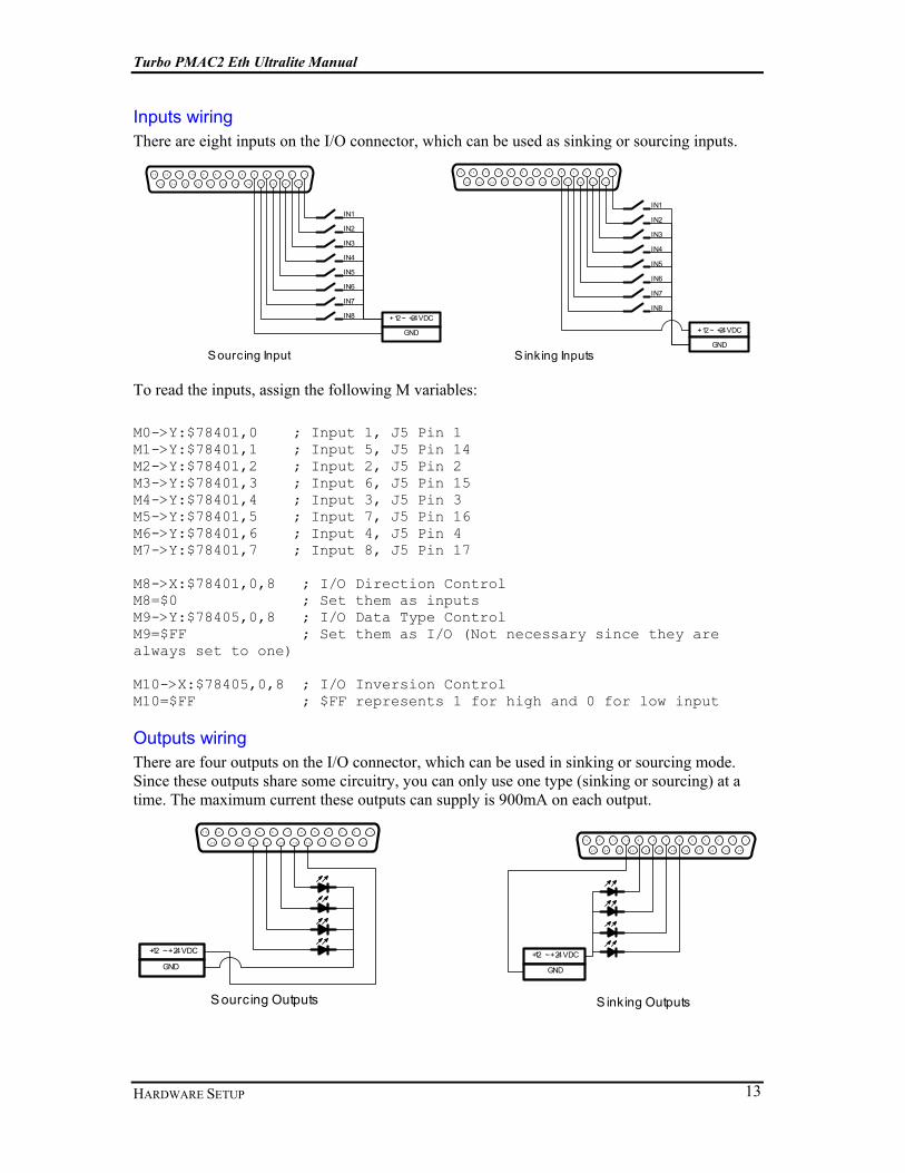
Inputs wiring There are eight inputs on the I/O connector, which can be used as sinking or sourcing inputs.
1234567891 01 11 21 3
1 41 51 61 71 81 92 02 12 22 32 42 5
+12 ~ +24VDC
GND
Sourcing Input
IN 1
IN 2
IN 3
IN 4
IN 5
IN 6
IN 7
IN 8
1234567891 01 11 21 3
1 41 51 61 71 81 92 02 12 22 32 42 5
+12 ~ +24VDC
GND
S inking Inputs
IN 1
IN 2
IN 3
IN 4
IN 5
IN 6
IN 7
IN 8
To read the inputs, assign the following M variables: M0->Y:$78401,0 ; Input 1, J5 Pin 1 M1->Y:$78401,1 ; Input 5, J5 Pin 14 M2->Y:$78401,2 ; Input 2, J5 Pin 2 M3->Y:$78401,3 ; Input 6, J5 Pin 15 M4->Y:$78401,4 ; Input 3, J5 Pin 3 M5->Y:$78401,5 ; Input 7, J5 Pin 16 M6->Y:$78401,6 ; Input 4, J5 Pin 4 M7->Y:$78401,7 ; Input 8, J5 Pin 17 M8->X:$78401,0,8 ; I/O Direction Control M8=$0 ; Set them as inputs M9->Y:$78405,0,8 ; I/O Data Type Control M9=$FF ; Set them as I/O (Not necessary since they are always set to one) M10->X:$78405,0,8 ; I/O Inversion Control M10=$FF ; $FF represents 1 for high and 0 for low input
Outputs wiring There are four outputs on the I/O connector, which can be used in sinking or sourcing mode. Since these outputs share some circuitry, you can only use one type (sinking or sourcing) at a time. The maximum current these outputs can supply is 900mA on each output.
1234567891 01 11 21 3
1 41 51 61 71 81 92 02 12 22 32 42 5
+12 ~ +24VDC
GND
Sourcing Outputs
1234567891 01 11 21 3
1 41 51 61 71 81 92 02 12 22 32 42 5
+12 ~ +24VDC
GND
S inking Outputs

Turbo PMAC2 Eth Ultralite Manual
HARDWARE SETUP 14
To write to the outputs, you need to define these M variables: M52->Y:$078402,2 ; DAT2 Line; J2 Pin 6 or 19 M53->Y:$078402,3 ; DAT3 Line; J2 Pin 7 or 20 M54->Y:$078402,4 ; DAT4 Line; J2 Pin 8 or 21 M55->Y:$078402,5 ; DAT5 Line; J2 Pin 9 or 22 M60->X:$078402,0,8 ; Direction control for DAT0 to DAT7 M61->Y:$078406,0,8 ; Data type control DAT0 to DAT7 M62->X:$078406,0,8 ; Data inversion control M60=$FF ;Setting the Direction control to 1, meaning outputs M61=$FF ;Setting data type to DATA on DAT0 to DAT7 M62=$0 ;Data inversion control for DAT0 to DAT7
Watchdog Relay wiring In addition to the I/O points and the E-stop on the General Purpose I/O connector, users can monitor the status of the controller by accessing the watchdog relay. As long as the controller is powered up and in the watchdog hasn’t tripped, indicating a functional controller, the relay is energized. As soon as the watchdog trips, the relay will be de-energized. Both normally closed and normally open contacts are available on pins 24 and 12 consequently with common contact on pin 11.
Auxiliary Connector, J8 A 15 pin DB-style female connector contains connections for Handwheel quadrature input, two ADC inputs, one DAC output and one Pulse and Direction output. Please check the software setup and connector pin out sections for more information on how to use each of these features.
J8 AUX
DB15 Female 12345678
91 01 11 21 31 41 5
Pin # Symbol Function
1 ADC1- Analog-to-Digital input, negative signal or DGND1 2 ADC2- Analog-to-Digital input, negative signal or DGND1 3 DAC1- ±10VDC output, inverted 4 DIR1- Direction output, inverted 5 PUL1- Pulse output, inverted

Turbo PMAC2 Eth Ultralite Manual
HARDWARE SETUP 15
6 HW1_CHA1- Handwheel Quadrature input A/ 7 HW1_CHB1- Handwheel Quadrature input B/ 8 DGND Digital Ground 9 ADC1+ Analog-to-Digital input, positive signal 10 ADC2+ Analog-to-Digital input, positive signal 11 DAC1+ ±10VDC output 12 DIR1+ Direction output 13 PUL1+ Pulse output 14 HW1_CHA1+ Handwheel Quadrature input A 15 HW1_CHB+ Handwheel Quadrature input B
1 to use the ADCs with single ended signal, connect the ADC1- and ADC2- to pin 8 DGND
Handwheel Wiring The Handwheel wiring should be done as shown in the following figure. You can either use differential or single-ended signals from any quadrature encoder. Make sure that you tie the ground connection of the encoder to the ground connection of the J8 if you’re planning to use a single-ended encoder. Since there is no power output pin available on J8, you need to power up the encoder from a separate source (i.e., JTHW).
12345678
91 01 11 21 31 41 5
Quadratue Encoder
A/AB/B
+5VDC
GND
Handwheel Wiring
To read the handwheel counts, you need to implement these settings in Encoder Conversion Table: I8000=$78410 M1010->X:$3501,0,24,s
You can access the position of the handwheel. You can also use the same address ($3501) as a master address for any of the motors (Ixx05)
Analog-to-Digital Connections (Option 12 required) There are two Analog-to-Digital circuits on J8 which can have 12-bit or 16-bit resolution based on the requested options. The signal can be either differential or single ended. In single ended configuration, the input range can be ±10VDC in contrast with ±5VDC in differential signal setting.
Turbo PMAC2 Eth Ultralite Manual
HARDWARE SETUP 16
Single-Ended Signal
+10VDC
-10VDC
GND on the analog signal side
J812345678
9101112131415
Differential Signal
J8
Differential S ignal 2
Differential S ignal 1
12345678
9101112131415
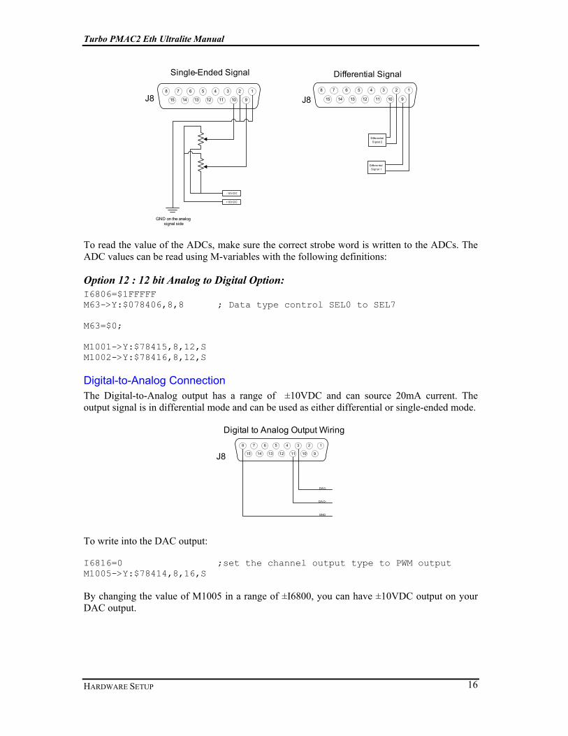
To read the value of the ADCs, make sure the correct strobe word is written to the ADCs. The ADC values can be read using M-variables with the following definitions:
Option 12 : 12 bit Analog to Digital Option: I6806=$1FFFFF M63->Y:$078406,8,8 ; Data type control SEL0 to SEL7 M63=$0; M1001->Y:$78415,8,12,S M1002->Y:$78416,8,12,S
Digital-to-Analog Connection The Digital-to-Analog output has a range of ±10VDC and can source 20mA current. The output signal is in differential mode and can be used as either differential or single-ended mode.
J8
DA C-
DA C+
GND
Digital to Analog Output Wiring12345678
9101112131415
To write into the DAC output:
I6816=0 ;set the channel output type to PWM output M1005->Y:$78414,8,16,S
By changing the value of M1005 in a range of ±I6800, you can have ±10VDC output on your DAC output.

Turbo PMAC2 Eth Ultralite Manual
HARDWARE SETUP 17
Note:
Please note that the DAC output is a filtered PWM signal and is limited by the max phase settings which cannot be changed because of Realtime Express network requirements.
Pulse and Direction Output This output can be connected to any stepper motor amplifier or it can be used to generate pulses for any other application. Since the phase and servo clock cycle times are preset at Realtime Express network’s update rate, the maximum output frequency with default settings is 327kHz which can be increased to 1.31 MHz by changing the PFM clock divider (I6803)
12345678
91 01 11 21 31 41 5
DI R-DI R+Pulse -Pulse +
G ND
Pulse & Direction Wiring
To output Pulse and Direction on the handwheel port :
I6826=3 ;set the channel output to PFM mode M1006->Y:$7841C,0,24,s
By changing the value of m1006, you can select the direction and the frequency of the pulses.
24 VDC Power Supply Input, J9 An external 24VDC power supply is required to power the Turbo PMAC2 Eth Ultralite. The 24V is wired into connector J9. The polarity of this connection is extremely important. Carefully follow the instructions in the wiring diagram. This connection can be made using 16 AWG wire directly from a protected power supply. In situations where the power supply is shared with other devices, it may be desirable to insert a filter in this connection. The power supply providing this 24V must be capable of providing an instantaneous current of at least 900 mA. In the case where multiple devices are driven from the same 24V supply, it is recommended that each device be wired back to the power supply terminals independently The connector for J9 is a Phoenix PCB Edge connector ZEC 1,5/ 3-ST-5,0 C2 R1,3 with Delta Tau part number 014-188305-001 and Phoenix part number 18883051.

Turbo PMAC2 Eth Ultralite Manual
HARDWARE SETUP 18
J9 24V DC Input Phoenix PCB Edge Connector
Pin # Symbol Function
1 GND Ground Connection from power supply 2 N.C. 3 +24V +24VDC input from power supply
MACRO Connector Based on the option that you have, either the MACRO fiber connector or the MACRO RJ45 connector is installed on the controller. • Option A provides the MACRO-ring fiber optic SC-style interface connector. The key
component on the board is U49.
MACRO SC-Style Fiber Connector
CN3 and CN4 Front View
OUT IN Pin # Symbol Function
1 IN MACRO Ring Receiver 2 OUT MACRO Ring Transmitter
1. The fiber optic version of MACRO uses 62.5/125 multi-mode glass fiber optic cable terminated in an SC-style connector. The optical wavelength is 1,300nm. 2. It is possible to "adapt" wire to fiber operation when using OPT B.
• Option C provides the MACRO-ring RJ-45 electrical interface connectors. The key
components on the board are CN3 and CN4.
MACRO RJ45 Connector
CN3 and CN4
Front View OUT IN
Pin # Symbol Function 1 DATA+ Differential MACRO Signal.
CN4: DATA+ input. CN3: DATA+ output. 2 DATA- Differential MACRO Signal.
CN4: DATA- input. CN3: DATA- output. 3 Unused Unused terminated pin. See schematic below. 4 Unused Unused terminated pin. See schematic below. 5 Unused Unused terminated pin. See schematic below. 6 Unused Unused terminated pin. See schematic below. 7 Unused Unused terminated pin. See schematic below. 8 Unused Unused terminated pin. See schematic below.
Thumbwheel Multiplexer Port (JTHW Port), J10
The Thumbwheel Multiplexer Port, or Multiplexer Port, on the JTHW connector has eight input lines and eight output lines. The output lines can be used to multiplex large numbers of inputs and outputs on the port, and Delta Tau provides accessory boards and software structures
Turbo PMAC2 Eth Ultralite Manual
HARDWARE SETUP 19
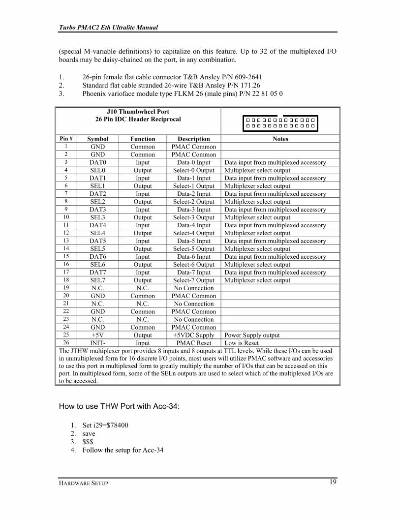
(special M-variable definitions) to capitalize on this feature. Up to 32 of the multiplexed I/O boards may be daisy-chained on the port, in any combination.
1. 26-pin female flat cable connector T&B Ansley P/N 609-2641 2. Standard flat cable stranded 26-wire T&B Ansley P/N 171.26 3. Phoenix varioface module type FLKM 26 (male pins) P/N 22 81 05 0
J10 Thumbwheel Port 26 Pin IDC Header Reciprocal 1
2
3
4
5
6
7
8
9
1 0
1 1
1 2
1 3
1 4
1 5
1 6
1 7
1 8
1 9
2 0
2 1
2 2
2 3
2 4
2 5
2 6
Pin # Symbol Function Description Notes
1 GND Common PMAC Common 2 GND Common PMAC Common 3 DAT0 Input Data-0 Input Data input from multiplexed accessory 4 SEL0 Output Select-0 Output Multiplexer select output 5 DAT1 Input Data-1 Input Data input from multiplexed accessory 6 SEL1 Output Select-1 Output Multiplexer select output 7 DAT2 Input Data-2 Input Data input from multiplexed accessory 8 SEL2 Output Select-2 Output Multiplexer select output 9 DAT3 Input Data-3 Input Data input from multiplexed accessory 10 SEL3 Output Select-3 Output Multiplexer select output 11 DAT4 Input Data-4 Input Data input from multiplexed accessory 12 SEL4 Output Select-4 Output Multiplexer select output 13 DAT5 Input Data-5 Input Data input from multiplexed accessory 14 SEL5 Output Select-5 Output Multiplexer select output 15 DAT6 Input Data-6 Input Data input from multiplexed accessory 16 SEL6 Output Select-6 Output Multiplexer select output 17 DAT7 Input Data-7 Input Data input from multiplexed accessory 18 SEL7 Output Select-7 Output Multiplexer select output 19 N.C. N.C. No Connection 20 GND Common PMAC Common 21 N.C. N.C. No Connection 22 GND Common PMAC Common 23 N.C. N.C. No Connection 24 GND Common PMAC Common 25 +5V Output +5VDC Supply Power Supply output 26 INIT- Input PMAC Reset Low is Reset
The JTHW multiplexer port provides 8 inputs and 8 outputs at TTL levels. While these I/Os can be used in unmultiplexed form for 16 discrete I/O points, most users will utilize PMAC software and accessories to use this port in multiplexed form to greatly multiply the number of I/Os that can be accessed on this port. In multiplexed form, some of the SELn outputs are used to select which of the multiplexed I/Os are to be accessed.
How to use THW Port with Acc-34:
1. Set i29=$78400 2. save 3. $$$ 4. Follow the setup for Acc-34

Turbo PMAC2 Eth Ultralite Manual
HARDWARE SETUP 20
How to use THW Port as general purpose IO (8 Input and 8 Output):
1. WX:$78400, $FF00 ;IO Direction Control 2. WY:$78404, $FFFF ;IO Data Type Control 3. WX:$78404, 0 ;IO Inversion Control M1000->Y:$78400,0,8 ;8 Inputs M1001->Y:$78400,8,8 ;8 Outputs

Turbo PMAC2 Eth Ultralite Manual
SOFTWARE SETUP 21
Software Setup
Host Communications To communicate with Turbo PMAC2 Eth Ultralite from your host computer, use any of the provided communication ports. The choice only affects the speed at which you will be talking to the controller. You can communicate with the controller over the Serial communication or Ethernet ports without any special software. A standard communications program such as HyperTerminal may be used on these ports, but the PMAC Executive PRO 2 Suite is recommended for development. For Serial RS-232 communications, please check the J7 pin outs for proper serial communication. For Ethernet communication, the default IP address is 192.6.94.5. You can use any terminal program to talk to the controller over these ports. In order to get the most out of the controller, we recommend Delta Tau’s PMAC Executive Pro2 Suite for communication. The PMAC Executive Pro2 Suite is designed for communication with all Delta Tau products. Although the suite includes all types of setup software programs for different types of controllers, you won’t be using all of them. The PEWIN32PRO2 is the main program used to setup your system and also for your application development and troubleshooting. You can also use the powerful functionality of the PMAC Plot Pro2 to gather information on the controller.
Pewin32PRO2 Communication Setup First, connect the controller to your PC. You don’t need any driver to get connected to the controller using the Serial or Ethernet port. Once you plug in the USB port, Windows will detect the controller and install the appropriate driver for communication with the controller. If you install the PMAC Executive Pro2 Suite before connecting the USB connection, Windows will detect the communication driver automatically.
Select the automatic installation of the drivers and click Next.

Turbo PMAC2 Eth Ultralite Manual
SOFTWARE SETUP 22
A pop-up window will state that it cannot verify the compatibility of the driver with Windows XP. Click the Continue Anyway button install the driver on your computer. You should then be able to see the device in Windows’ Device Manager.
Once you have established connection between the controller and the computer, start your software by clicking on the Pewin32PRO2 icon either from your desktop or from the Start menu.
Turbo PMAC2 Eth Ultralite Manual
SOFTWARE SETUP 23
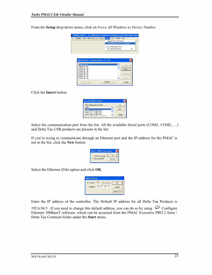
From the Setup drop-down menu, click on Force All Windows to Device Number.
Click the Insert button.
Select the communication port from the list. All the available Serial ports (COM1, COM2, …) and Delta Tau USB products are present in the list. If you’re trying to communicate through an Ethernet port and the IP address for the PMAC is not in the list, click the New button:
Select the Ethernet (Eth) option and click OK.
Enter the IP address of the controller. The Default IP address for all Delta Tau Products is
192.6.94.5 . If you need to change this default address, you can do so by using Configure Ethernet 100BaseT software, which can be accessed from the PMAC Executive PRO 2 Suite / Delta Tau Common folder under the Start menu.

Turbo PMAC2 Eth Ultralite Manual
SOFTWARE SETUP 24
After selecting the communication port with the controller, click OK.
The selected device is now added to the list, and is referred to as PMAC ##. You can have up to 32 PMAC devices defined on the software.
To check the communications, click the Test button. If communication is successful, you will see a confirmation message.
In the case of Ethernet Communication, the Pcommserver will report the result of the PING command to the network driver chip on the controller before trying to communicate to the controller CPU.
Once communication is established, you can use any of the windows and tools provided by the Pewin32PRO2 software and accompanied tools.