EGX-350 Hardware Setup Procedures
26
EGX-350 Hardware Setup Guide
-
Upload
vetty-valentin -
Category
Documents
-
view
227 -
download
0
Transcript of EGX-350 Hardware Setup Procedures
7/28/2019 EGX-350 Hardware Setup Procedures
http://slidepdf.com/reader/full/egx-350-hardware-setup-procedures 1/26

7/28/2019 EGX-350 Hardware Setup Procedures
http://slidepdf.com/reader/full/egx-350-hardware-setup-procedures 2/26

7/28/2019 EGX-350 Hardware Setup Procedures
http://slidepdf.com/reader/full/egx-350-hardware-setup-procedures 3/26
EGX-350 Hardware
Configuration forNosecone Engraving

7/28/2019 EGX-350 Hardware Setup Procedures
http://slidepdf.com/reader/full/egx-350-hardware-setup-procedures 4/26
NOTES:
EGX-350 Setup for NoseconeEngraving Power the units primary power switch on the right
rear of the unit.
Turn the Emergency (secondary power) switchclockwise to power the unit on.
The Handy Panel will power on and display themodel and boot version. Once completed thedisplay will read “HIT ENTER”.
At this point press the ENTER key to initialize theunit.
Once the initialization is completed, the carriage
will be located to the View position (Left rear).
Place the adhesive sheet (AS-10) in the lower leftcorner of the table and place the material in thecorner as well.

7/28/2019 EGX-350 Hardware Setup Procedures
http://slidepdf.com/reader/full/egx-350-hardware-setup-procedures 5/26

7/28/2019 EGX-350 Hardware Setup Procedures
http://slidepdf.com/reader/full/egx-350-hardware-setup-procedures 6/26
NOTES:
EGX-350 Setup for NoseconeEngraving On the EGX-350 set the lock lever to either 1 or 2
by pressing the lever in and then down. This willallow the Z Axis to “float up and down”.
Using the arrow keys on the control panel movethe carriage so that the spindle unit is over thelower left corner of the material.
Once the spindle is over the lower left corner of the material, press the XY ORIGIN SET button andpress the ENTER key to set that as your originpoint.
Remove the cutter tool from the cutter knob(brass knob) and install the cutter knob on the
top of the spindle assembly.

7/28/2019 EGX-350 Hardware Setup Procedures
http://slidepdf.com/reader/full/egx-350-hardware-setup-procedures 7/26

7/28/2019 EGX-350 Hardware Setup Procedures
http://slidepdf.com/reader/full/egx-350-hardware-setup-procedures 8/26

7/28/2019 EGX-350 Hardware Setup Procedures
http://slidepdf.com/reader/full/egx-350-hardware-setup-procedures 9/26
EGX-350 Hardware
Configuration for Non-Nosecone Engraving

7/28/2019 EGX-350 Hardware Setup Procedures
http://slidepdf.com/reader/full/egx-350-hardware-setup-procedures 10/26
NOTES:
EGX-350 Setup for Non-Nosecone Engraving Power the units primary power switch on the right
rear of the unit.
Turn the Emergency (secondary power) switchclockwise to power the unit on.
The Handy Panel will power on and display themodel and boot version. Once completed thedisplay will read “HIT ENTER”.
At this point press the ENTER key to initialize theunit.
Once the initialization is completed, the carriage
will be located to the View position (Left rear).
Place the adhesive sheet (AS-10) in the lower leftcorner of the table and place the material in thecorner as well.

7/28/2019 EGX-350 Hardware Setup Procedures
http://slidepdf.com/reader/full/egx-350-hardware-setup-procedures 11/26
NOTES:
EGX-350 Setup for Non-Nosecone Engraving On the Handy Panel press the MENU key multiple
times until you see the I/O, OTHERS,ADJUSTMENT menu.
Using the arrow keys on the Handy Panel movethe cursor to OTHERS and press the ENTER key toenter the sub-menu.
Press the MENU key multiple times until you seeAUTO Z CONTROL.
Using the arrow keys on the Handy Panel movethe cursor to OFF and press the ENTER key to setthe value (shown with brackets).
The display will display SET lock lever to 3 for afew seconds and return the AUTO Z CONTROLscreen.

7/28/2019 EGX-350 Hardware Setup Procedures
http://slidepdf.com/reader/full/egx-350-hardware-setup-procedures 12/26
NOTES:
EGX-350 Setup for Non-Nosecone Engraving On the EGX-350 set the lock lever to 3 by
pressing the lever in and then down. This will lockthe Z Axis position.
Using the arrow keys on the control panel movethe carriage so that the spindle unit is over thelower left corner of the material.
Once the spindle is over the lower left corner of the material, press the XY ORIGIN SET button andpress the ENTER key to set that as your originpoint.
Remove the cutter tool from the cutter knob(brass knob) and install the cutter knob on the
top of the spindle assembly.

7/28/2019 EGX-350 Hardware Setup Procedures
http://slidepdf.com/reader/full/egx-350-hardware-setup-procedures 13/26
NOTES:
EGX-350 Setup for Non-Nosecone Engraving Install the collet to the bottom of the spindle
assembly and tighten it with the supplied spannerwrenches.
Using the arrow keys move the nosecone over aflat area of the material.
Using the Z- key lower the nosecone until thebottom of the collet is approx 10mm above thematerial.
Insert the cutter until it touches the material andlock in place with the supplied hex wrench.
Press the Z ORIGIN SET key to bring up the Zsettings on the display.
Using the arrow keys move the cursor over Z0and press the ENTER key to set this position asthe surface.

7/28/2019 EGX-350 Hardware Setup Procedures
http://slidepdf.com/reader/full/egx-350-hardware-setup-procedures 14/26
NOTES:
EGX-350 Setup for Non-Nosecone Engraving Press the Z+ key to raise the tool off the surface
approximately 1/8”.
Press the arrow key to move the cursor to Z2 andpress the ENTER key to set this value as theclearance gap.
NEVER set Z1 on the machine. Z1 is the amountof depth you want to cut and is controlled via the
software.
Your machine is now ready for non-noseconeengraving.

7/28/2019 EGX-350 Hardware Setup Procedures
http://slidepdf.com/reader/full/egx-350-hardware-setup-procedures 15/26
EGX-350 Hardware
Configuration forScribing

7/28/2019 EGX-350 Hardware Setup Procedures
http://slidepdf.com/reader/full/egx-350-hardware-setup-procedures 16/26
NOTES:
EGX-350 Setup for Scribing
Power the units primary power switch on the rightrear of the unit.
Turn the Emergency (secondary power) switchclockwise to power the unit on.
The Handy Panel will power on and display themodel and boot version. Once completed thedisplay will read “HIT ENTER”.
At this point press the ENTER key to initialize theunit.
Once the initialization is completed, the carriagewill be located to the View position (Left rear).
Place the adhesive sheet (AS-10) in the lower leftcorner of the table and place the material in thecorner as well.
7/28/2019 EGX-350 Hardware Setup Procedures
http://slidepdf.com/reader/full/egx-350-hardware-setup-procedures 17/26
NOTES:
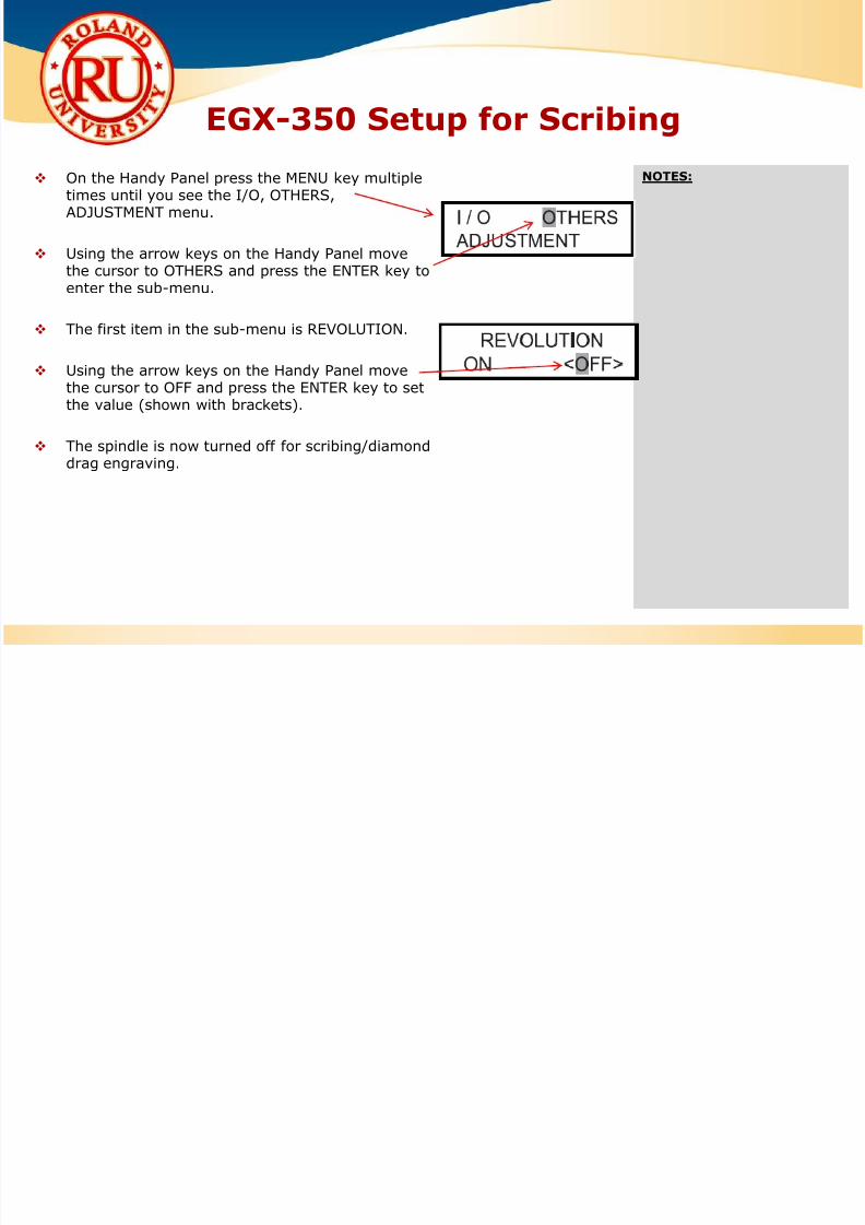
EGX-350 Setup for Scribing
On the Handy Panel press the MENU key multipletimes until you see the I/O, OTHERS,ADJUSTMENT menu.
Using the arrow keys on the Handy Panel movethe cursor to OTHERS and press the ENTER key toenter the sub-menu.
The first item in the sub-menu is REVOLUTION.
Using the arrow keys on the Handy Panel movethe cursor to OFF and press the ENTER key to setthe value (shown with brackets).
The spindle is now turned off for scribing/diamonddrag engraving.

7/28/2019 EGX-350 Hardware Setup Procedures
http://slidepdf.com/reader/full/egx-350-hardware-setup-procedures 18/26
NOTES:
EGX-350 Setup for Scribing
Press the MENU key multiple times until you seeAUTO Z CONTROL.
Using the arrow keys on the Handy Panel movethe cursor to ON and press the ENTER key to setthe value (shown with brackets).
The display will display SET lock lever to 1 or 2 fora few seconds and return the AUTO Z CONTROL
screen.

7/28/2019 EGX-350 Hardware Setup Procedures
http://slidepdf.com/reader/full/egx-350-hardware-setup-procedures 19/26
NOTES:
EGX-350 Setup for Scribing
On the EGX-350 set the lock lever to either 1 or 2by pressing the lever in and then down. This willallow the Z Axis to “float up and down”.
Using the arrow keys on the control panel movethe carriage so that the spindle unit is over thelower left corner of the material.
Once the spindle is over the lower left corner of
the material, press the XY ORIGIN SET button andpress the ENTER key to set that as your originpoint.
Remove the cutter tool from the cutter knob(brass knob) and install the cutter knob on the
top of the spindle assembly.

7/28/2019 EGX-350 Hardware Setup Procedures
http://slidepdf.com/reader/full/egx-350-hardware-setup-procedures 20/26
NOTES:
EGX-350 Setup for Scribing
Install the collet to the bottom of the spindleassembly and tighten it with the supplied spannerwrenches.
Insert the diamond scraper tool into the cutterholder and have the tool protrude from thebottom of the collet by at least 10mm.
Tighten the tool in place with the supplied hex
wrench.
Your machine is now ready to diamond scribe.

7/28/2019 EGX-350 Hardware Setup Procedures
http://slidepdf.com/reader/full/egx-350-hardware-setup-procedures 21/26
EGX-350 Hardware
Configuration forRhinestone Template
Creation(when using R-WearStudio)

7/28/2019 EGX-350 Hardware Setup Procedures
http://slidepdf.com/reader/full/egx-350-hardware-setup-procedures 22/26
NOTES:
EGX-350 Setup for RhinestoneTemplate Creation Power the units primary power switch on the right
rear of the unit.
Turn the Emergency (secondary power) switchclockwise to power the unit on.
The Handy Panel will power on and display themodel and boot version. Once completed thedisplay will read “HIT ENTER”.
At this point press the ENTER key to initialize theunit.
Once the initialization is completed, the carriagewill be located to the View position (Left rear).
Place the adhesive sheet (AS-10) in the lower leftcorner of the table and place the material in thecorner as well.

7/28/2019 EGX-350 Hardware Setup Procedures
http://slidepdf.com/reader/full/egx-350-hardware-setup-procedures 23/26
NOTES: On the Handy Panel press the MENU key multipletimes until you see the I/O, OTHERS,ADJUSTMENT menu.
Using the arrow keys on the Handy Panel movethe cursor to OTHERS and press the ENTER key toenter the sub-menu.
Press the MENU key multiple times until you see
AUTO Z CONTROL.
Using the arrow keys on the Handy Panel movethe cursor to OFF and press the ENTER key to setthe value (shown with brackets).
The display will display SET lock lever to 3 for afew seconds and return the AUTO Z CONTROLscreen.
EGX-350 Setup for RhinestoneTemplate Creation

7/28/2019 EGX-350 Hardware Setup Procedures
http://slidepdf.com/reader/full/egx-350-hardware-setup-procedures 24/26
NOTES:
EGX-350 Setup for RhinestoneTemplate Creation On the EGX-350 set the lock lever to 3 by
pressing the lever in and then down. This will lockthe Z Axis position.
Measure and mark the center of the material.
Using the arrow keys on the control panel movethe carriage so that the spindle unit is over thecenter of the material.
Once the spindle is over the lower left corner of the material, press the XY ORIGIN SET button andpress the ENTER key to set that as your originpoint.
Remove the cutter tool from the cutter knob(brass knob) and install the cutter knob on thetop of the spindle assembly.

7/28/2019 EGX-350 Hardware Setup Procedures
http://slidepdf.com/reader/full/egx-350-hardware-setup-procedures 25/26
NOTES:
EGX-350 Setup for RhinestoneTemplate Creation Install the collet to the bottom of the spindle
assembly and tighten it with the supplied spannerwrenches.
Using the arrow keys move the nosecone over aflat area of the material.
Using the Z- key lower the nosecone until thebottom of the collet is approx 10mm above the
material.
Insert the cutter until it touches the material andlock in place with the supplied hex wrench.
Press the Z ORIGIN SET key to bring up the Zsettings on the display.
Using the arrow keys move the cursor over Z0and press the ENTER key to set this position asthe surface (noted by brackets).

7/28/2019 EGX-350 Hardware Setup Procedures
http://slidepdf.com/reader/full/egx-350-hardware-setup-procedures 26/26
NOTES:
EGX-350 Setup for RhinestoneTemplate Creation Press the Z+ key to raise the tool off the surface
approximately 1/8”.
Press the arrow key to move the cursor to Z2 andpress the ENTER key to set this value as theclearance gap (noted by brackets).
NEVER set Z1 on the machine. Z1 is the amountof depth you want to cut and is controlled via the
software.
Your machine is now ready for rhinestonetemplate creation via R-WearStudio.
Design your template in R-WearStudio.
When you select Engrave, ensure that theEngrave Position is set for Center.