1 ECE 545—Digital System Design with VHDL Lecture 6 Behavioral VHDL Coding (for Synthesis): Finite...
80
1 ECE 545—Digital System Design with VHDL Lecture 6 Behavioral VHDL Coding (for Synthesis): Finite State Machines and ASMs 9/30/08
-
Upload
brett-adams -
Category
Documents
-
view
224 -
download
2
Transcript of 1 ECE 545—Digital System Design with VHDL Lecture 6 Behavioral VHDL Coding (for Synthesis): Finite...

1
ECE 545—Digital System Design with VHDLLecture 6
Behavioral VHDL Coding (for Synthesis): Finite State Machines and ASMs
9/30/08

2
Outline
• Behavioral VHDL Coding for Synthesis• Coding for Simple Finite State Machines
• Moore Machine• Mealy Machine
• Coding for Algorithmic State Machines• Bit-counting example

3
Resources
• Volnei A. Pedroni, Circuit Design with VHDL• Chapter 8, State Machines
• Stephen Brown and Zvonko Vranesic, Fundamentals of Digital Logic with VHDL Design, 2nd Edition• Chapter 8.10 Algorithmic State Machine (ASM) Charts• Chapter 10.2.6 Sort Operation • (from handouts distributed in class)

4
VHDL Design Styles (Architecture)
STRUCTURAL
components andinterconnects
VHDL Design Styles
DATAFLOW
“concurrent” statements • Sequential Logic
(registers, counters)• State machines (FSMs, ASMs) • Complex Comb. Logic
“sequential” statements
NON-SYNTHESIZABLESYNTHESIZABLE
BEHAVIORAL
• Test Benches• Modeling IP• Gates
• Simple Comb. Logic

5
Coding for Simple Finite State Machines

6
Moore versus Mealy Machines
Register OutputComb. Logic
Next StateComb. Logic
Input Output
ClockReset
Moore Machine: Next State = Function(Input, Present State), Output = Function(Present State)
Present State
Next State
Register OutputComb. Logic
Next StateComb. Logic
Input Output
ClockReset
Mealy Machine: Next State = Function(Input, Present State), Output = Function(Present State, Input)
Present State
Next State
7
Coding for Moore Machines

8
Moore Machines
Register OutputComb. Logic
Next StateComb. Logic
Input Output
ClockReset
Present State
Next State
NEXT STATEFUNCTION:
process(input, present state)
FSM REGISTER:
process(reset,clock)
OUTPUTFUNCTION:
process(present state) OR
use concurrent code

9
Template for Moore Machines
architecture behavioral of fsm_example is
type state is (S0, S1, S2, S3); -- define the state type
signal pr_state, nx_state: state; -- declare present state and next state
begin
-- section 1: fsm register
process (resetn,clock)
begin
if (resetn='0') then
pr_state <= S0; -- choose reset state
elsif (clock'event and clock='1') then
pr_state <= nx_state;
end if;
end process;

10
Template for Moore Machines cont'd
-- section 2: next state function
process (input, pr_state)
begin
case pr_state is
when S0 =>
if (input = . . . ) then
nx_state <= S1;
else
nx_state <= S2;
end if;
. . .
end case;
end process;
-- section 3: output function
process (pr_state) –- or can use concurrent statements
begin
output <= . . .
. . .
end
end behavioral;

11
S2 z 1 =
resetn
S1 z 0 = S0 z 0 = w 0 =
w 1 =
w 1 =
w 0 =
w 0 = w 1 =
Function: Detect if two consecutive inputs are '1's
Moore Example FSM

12
Present Next state Outputstate w = 0 w = 1 z
S0 S0 S1 0 S1 S0 S2 0 S2 S0 S2 1
Moore Example FSM: State Table

13
Moore FSM: VHDL Code
library IEEE;
use IEEE.STD_LOGIC_1164.all;
entity moore_fsm is
port(w : in STD_LOGIC;
clock : in STD_LOGIC;
resetn : in STD_LOGIC;
z : out STD_LOGIC);
end moore_fsm;
architecture behavioral of moore_fsm is
type state is (S0, S1, S2);
signal pr_state, nx_state: state;
begin
-- section 1: fsm register
process (resetn,clock)
begin
if (resetn='0') then
pr_state <= S0; -- reset state
elsif (clock'event and clock='1') then
pr_state <= nx_state;
end if;
end process;

14
Moore FSM: VHDL Code cont'd
-- section 2: next state function
process (w, pr_state) -- sensitive to both input and present state
begin
case pr_state is
when S0 =>
if (w = '0') then
nx_state <= S0;
else
nx_state <= S1;
end if;
when S1 =>
if (w = '0') then
nx_state <= S0;
else
nx_state <= S2;
end if;

15
Moore FSM: VHDL Code cont'd
when S2 =>
if (w = '0') then
nx_state <= S0;
else
nx_state <= S2;
end if;
end case;
end process;
-- section 3: output function
z <= '1' when pr_state = S2 else '0';
-- or can use process statement:
-- process(pr_state) -- sensitive to present state only
-- begin
-- if pr_state = S2 then z <='1'; else z<='0'; end if;
-- end process;
end behavioral;
16
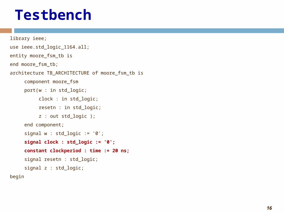
Testbench
library ieee;
use ieee.std_logic_1164.all;
entity moore_fsm_tb is
end moore_fsm_tb;
architecture TB_ARCHITECTURE of moore_fsm_tb is
component moore_fsm
port(w : in std_logic;
clock : in std_logic;
resetn : in std_logic;
z : out std_logic );
end component;
signal w : std_logic := '0';
signal clock : std_logic := '0';
constant clockperiod : time := 20 ns;
signal resetn : std_logic;
signal z : std_logic;
begin
17
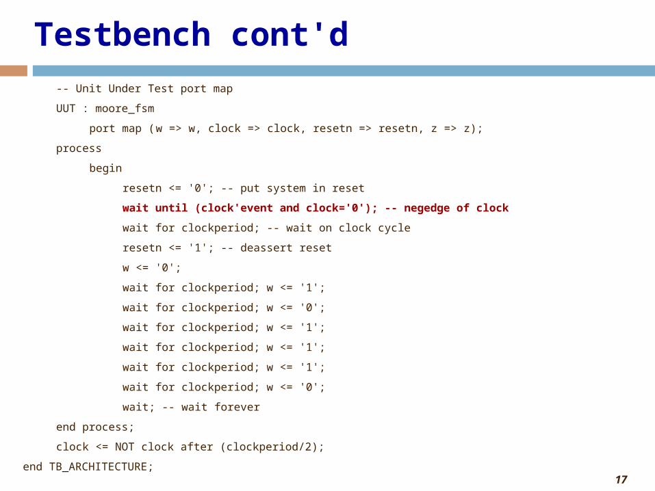
Testbench cont'd
-- Unit Under Test port map
UUT : moore_fsm
port map (w => w, clock => clock, resetn => resetn, z => z);
process
begin
resetn <= '0'; -- put system in reset
wait until (clock'event and clock='0'); -- negedge of clock
wait for clockperiod; -- wait on clock cycle
resetn <= '1'; -- deassert reset
w <= '0';
wait for clockperiod; w <= '1';
wait for clockperiod; w <= '0';
wait for clockperiod; w <= '1';
wait for clockperiod; w <= '1';
wait for clockperiod; w <= '1';
wait for clockperiod; w <= '0';
wait; -- wait forever
end process;
clock <= NOT clock after (clockperiod/2);
end TB_ARCHITECTURE;

18
Waveform
NOTE: Inputs change on negedge of clock
19
Coding Alternative: Merging sections 2 & 3
• Can also merge section 2 (next state function) and section 3 (output function)
• For code compactness and/or readability

20
Moore FSM: VHDL Code (Merging Next State Function and Output Function)
library IEEE;
use IEEE.STD_LOGIC_1164.all;
entity moore_fsm is
port(w : in STD_LOGIC;
clock : in STD_LOGIC;
resetn : in STD_LOGIC;
z : out STD_LOGIC);
end moore_fsm;
architecture behavioral of moore_fsm is
type state is (S0, S1, S2);
signal pr_state, nx_state: state;
begin
-- section 1: fsm register
process (resetn,clock)
begin
if (resetn='0') then
pr_state <= S0;
elsif (clock'event and clock='1') then
pr_state <= nx_state;
end if;
end process;
21
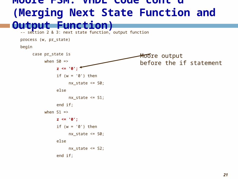
Moore FSM: VHDL Code cont'd(Merging Next State Function and Output Function)
-- section 2 & 3: next state function, output function
process (w, pr_state)
begin
case pr_state is
when S0 =>
z <= '0';
if (w = '0') then
nx_state <= S0;
else
nx_state <= S1;
end if;
when S1 =>
z <= '0';
if (w = '0') then
nx_state <= S0;
else
nx_state <= S2;
end if;
Moore outputbefore the if statement
22
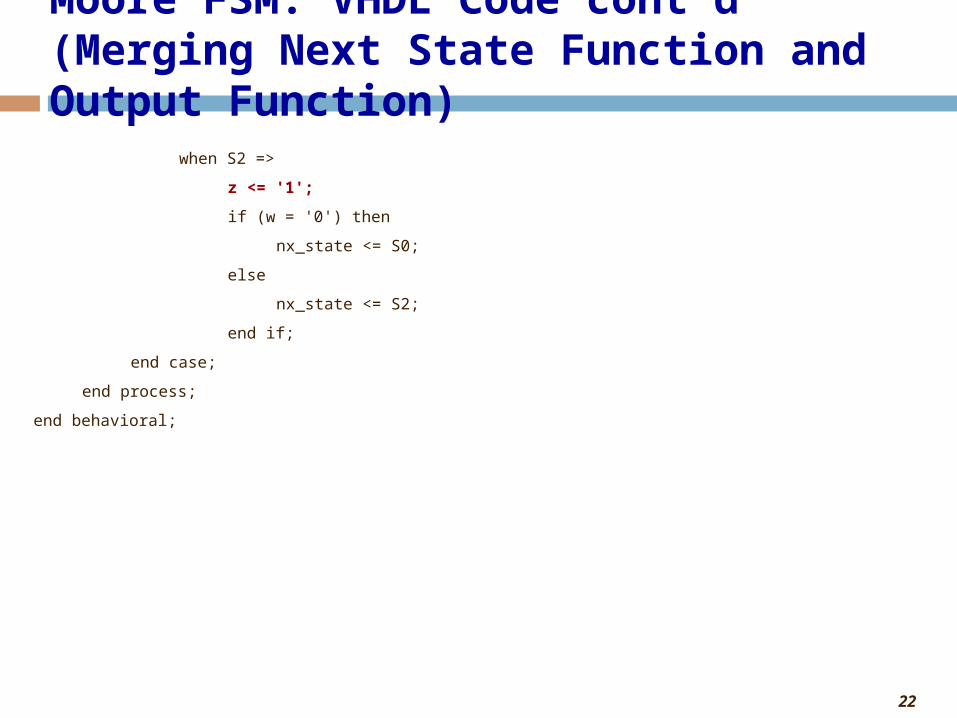
Moore FSM: VHDL Code cont'd(Merging Next State Function and Output Function)
when S2 =>
z <= '1';
if (w = '0') then
nx_state <= S0;
else
nx_state <= S2;
end if;
end case;
end process;
end behavioral;

23
Coding for Mealy Machines

24
Mealy Machines
Register OutputComb. Logic
Next StateComb. Logic
Input Output
ClockReset
Present State
Next State
NEXT STATEFUNCTION:
process(input, present state)
FSM REGISTER:
process(reset,clock)
OUTPUTFUNCTION:
process(input, present state) OR
use concurrent code
Difference between Moore and Mealy is sensitivity to input

25
Template for Mealy Machines
architecture behavioral of fsm_example is
type state is (S0, S1, S2, S3);
signal pr_state, nx_state: state;
begin
-- section 1: fsm register
process (resetn,clock)
begin
if (resetn='0') then
pr_state <= S0; -- reset state
elsif (clock'event and clock='1') then
pr_state <= nx_state;
end if;
end process;
26
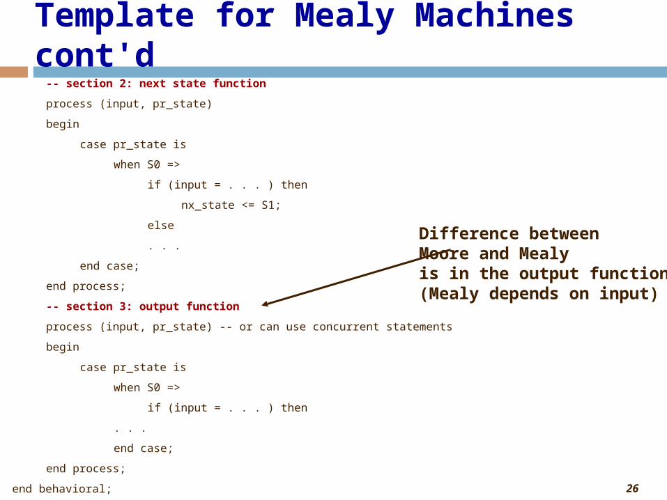
Template for Mealy Machines cont'd-- section 2: next state function
process (input, pr_state)
begin
case pr_state is
when S0 =>
if (input = . . . ) then
nx_state <= S1;
else
. . .
end case;
end process;
-- section 3: output function
process (input, pr_state) -- or can use concurrent statements
begin
case pr_state is
when S0 =>
if (input = . . . ) then
. . .
end case;
end process;
end behavioral;
Difference betweenMoore and Mealyis in the output function(Mealy depends on input)

27
S0
w 0 = z 0 =
w 1 = z 1 = S1 w 0 = z 0 =
resetn
w 1 = z 0 =
Mealy Example FSM
Function: Detect if two consecutive inputs are '1's

28
Present Next state Output z
state w = 0 w = 1 w = 0 w = 1
A A B 0 0 B A B 0 1
Mealy Example FSM – State Table
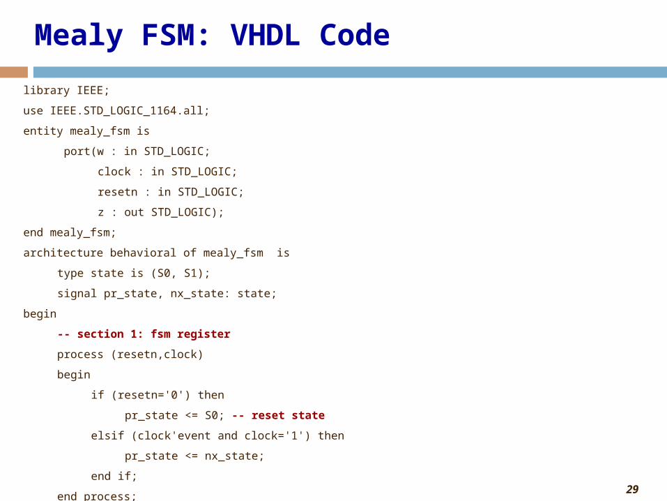
29
Mealy FSM: VHDL Code
library IEEE;
use IEEE.STD_LOGIC_1164.all;
entity mealy_fsm is
port(w : in STD_LOGIC;
clock : in STD_LOGIC;
resetn : in STD_LOGIC;
z : out STD_LOGIC);
end mealy_fsm;
architecture behavioral of mealy_fsm is
type state is (S0, S1);
signal pr_state, nx_state: state;
begin
-- section 1: fsm register
process (resetn,clock)
begin
if (resetn='0') then
pr_state <= S0; -- reset state
elsif (clock'event and clock='1') then
pr_state <= nx_state;
end if;
end process;
30
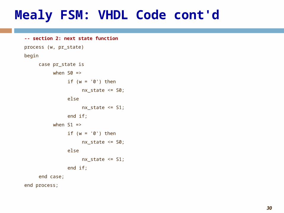
Mealy FSM: VHDL Code cont'd
-- section 2: next state function
process (w, pr_state)
begin
case pr_state is
when S0 =>
if (w = '0') then
nx_state <= S0;
else
nx_state <= S1;
end if;
when S1 =>
if (w = '0') then
nx_state <= S0;
else
nx_state <= S1;
end if;
end case;
end process;

31
Mealy FSM: VHDL Code cont'd
-- section 3: output function
process(w, pr_state) -- sensitive to both input and present state
begin
case pr_state is
when S0 =>
z <= '0';
when S1 =>
if (w = '0') then
z <= '0';
else
z <= '1';
end if;
end case;
end process;
-- or can use concurrent code:
-- z <= '1' when (pr_state = S1 and w = '1') else '0';
end behavioral;

32
Testbench
• Same as for Moore (just change the word moore to mealy)
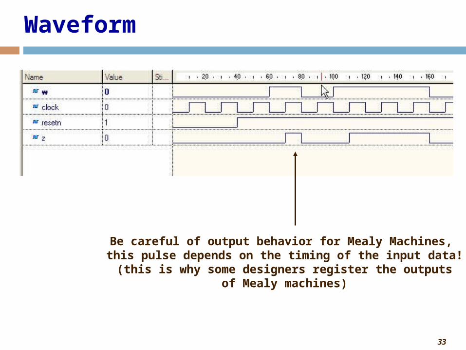
33
Waveform
Be careful of output behavior for Mealy Machines, this pulse depends on the timing of the input data!(this is why some designers register the outputs
of Mealy machines)

34
Coding Alternative: Merging sections 2 & 3
• Can also merge section 2 (next state function) and section 3 (output function)
• For code compactness and/or readability

35
Mealy FSM: VHDL Code (Merging Next State Function and Output Function)
library IEEE;
use IEEE.STD_LOGIC_1164.all;
entity mealy_fsm is
port(w : in STD_LOGIC;
clock : in STD_LOGIC;
resetn : in STD_LOGIC;
z : out STD_LOGIC);
end mealy_fsm;
architecture behavioral of mealy_fsm is
type state is (S0, S1);
signal pr_state, nx_state: state;
begin
-- section 1: fsm register
process (resetn,clock)
begin
if (resetn='0') then
pr_state <= S0;
elsif (clock'event and clock='1') then
pr_state <= nx_state;
end if;
end process;

36
Mealy FSM: VHDL Code cont'd(Merging Next State Function and Output Function)
-- sections 2 & 3: next state function, output function
process (w, pr_state) begin
case pr_state is
when S0 =>
if (w = '0') then
nx_state <= S0;
z <= '0';
else
nx_state <= S1;
z <= '0';
end if;
when S1 =>
if (w = '0') then
nx_state <= S0;
z <= '0';
else
nx_state <= S1;
z <= '1';
end if;
end case;
end process;
end behavioral;
NOTE: z<='0' can be moved before the IF statement. Some Mealy outputs act like Moore outputs.
Normally, Mealy output goes after the if statement

37
VHDL Coding: Mealy versus Moore Summary
• Code in three sections• Section 1: FSM register (same for Mealy, Moore)• Section 2: Next state function (same for Mealy, Moore)• Section 3: Output function
• Code using concurrent statements or process statement• Moore depends present state only• Mealy depends on present state and input
• Can merge sections 2 and 3 together• Moore assigns the output before the if statement• Mealy assigns the output after the if statement
38
State Encoding

39
State Encoding Problem
• State Encoding Can Have a Big Influence on Optimality of the FSM Implementation• No methods other than checking all possible encodings
are known to produce optimal circuit• Feasible for small circuits only
• Using Enumerated Types for States in VHDL Leaves Encoding Problem for Synthesis Tool

40
Types of State Encoding
• Binary (Sequential) – States Encoded as Consecutive Binary Numbers• Small number of used flip-flops• Potentially complex transition functions leading to slow
implementations• One-Hot – Only One Bit Is Active
• Number of used flip-flops as big as number of states• Simple and fast transition functions• Preferable coding technique in FPGAs

41
Binary versus One-Hot
State Binary Code One-Hot CodeS0 000 10000000S1 001 01000000S2 010 00100000S3 011 00010000S4 100 00001000S5 101 00000100S6 110 00000010S7 111 00000001
42
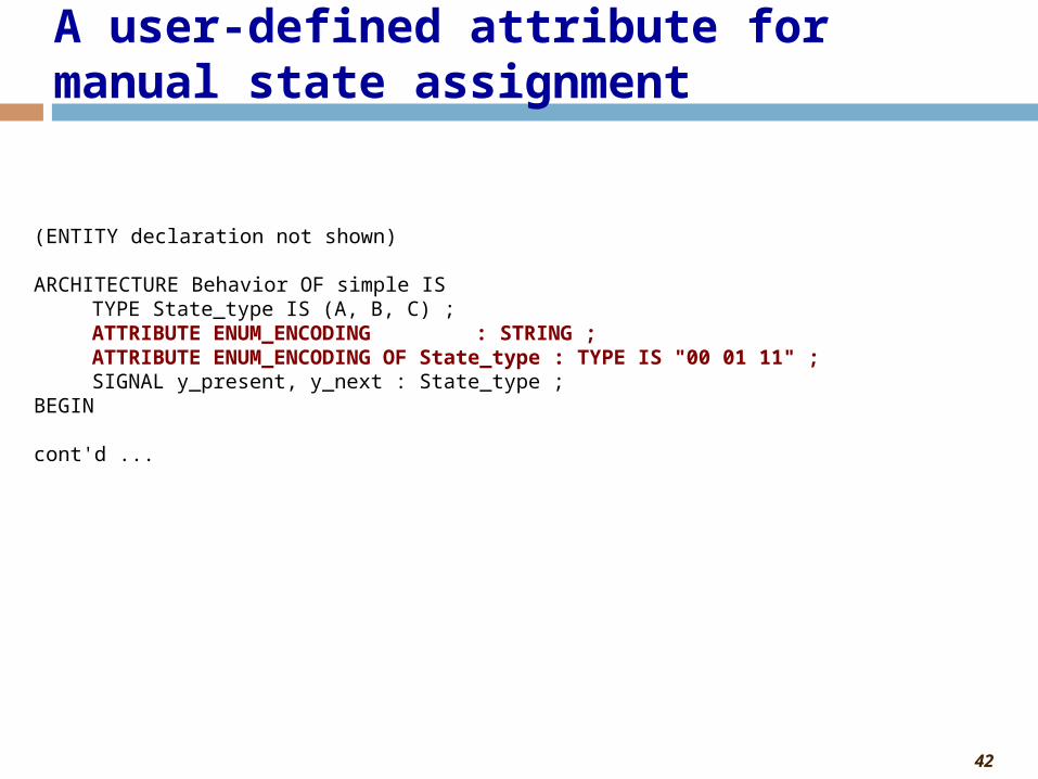
(ENTITY declaration not shown)
ARCHITECTURE Behavior OF simple ISTYPE State_type IS (A, B, C) ;ATTRIBUTE ENUM_ENCODING : STRING ;ATTRIBUTE ENUM_ENCODING OF State_type : TYPE IS "00 01 11" ;SIGNAL y_present, y_next : State_type ;
BEGIN
cont'd ...
A user-defined attribute for manual state assignment

43
ARCHITECTURE Behavior OF simple IS SUBTYPE ABC_STATE is STD_LOGIC_VECTOR(1 DOWNTO 0);
CONSTANT A : ABC_STATE := "00" ;CONSTANT B : ABC_STATE := "01" ;CONSTANT C : ABC_STATE := "11" ;
SIGNAL y_present, y_next : ABC_STATE;BEGIN
PROCESS ( w, y_present )BEGIN
CASE y_present ISWHEN A =>
IF w = '0' THEN y_next <= A ;ELSE y_next <= B ;END IF ;
cont'd . . .
Using constants for manual state assignment

44
VHDL Coding for Algorithmic State Machines

45
Complex Digital Design: ASM Design Steps
• Given a specification, to design a complex digital system using ASMs, the following steps are involved:
1. Translate specification into pseudocode.2. Translate pseudocode into a high-level ASM. Also called pseudocode ASM,
since it uses pseudocode instead of actual signal names.3. Design a datapath block diagram based on high-level ASM. Also called an
execution unit. (Some references decompose block diagram into a datapath block diagram and controller block diagram.)
4. Draw top-level interface diagram. This diagram connects the datapath with the controller to show all inputs, outputs, and internal connections of the entire digital system.
5. Design detailed controller ASM based on high-level ASM. Detailed means using the exact signal names, not pseudocode representations.
• After this process you have three results:• Datapath: represented by a datapath block diagram • Controller: represented by a detailed controller ASM • Top-Level: represented by top-level interface diagram
• From this it is “easy” to translate into VHDL

46
How to "easily" translate into VHDL
• Given 5 ASM design steps are complete, translate into VHDL
• 3 VHDL translation steps:1. Code detailed controller FSM using detailed controller
FSM and top-level interface diagram
2. Code datapath using datapath block diagram and top-level interface diagram
3. Code top-level using top-level interface diagram

47
Coding Step 1: Detailed Controller FSM
• We code the detailed controller FSM about the same as we would any Moore or Mealy FSM
• Use the top-level interface diagram to help with entity ports (inputs and outputs)• Section 1: FSM Register
• Reset and clocking in of next state• Same as described earlier for simple FSM
• Section 2: Next state function• Use the detailed controller ASM to create the next state function• Same as described earlier for simple FSM
• Section 3: Output function• This is slightly different than the simple FSM described earlier• First, set all outputs to default: this saves on typing and eliminates potential errors
• Most of the time the outputs of the FSM (which go to the controller or to the outside world) are the same value.
• Only indicate when the FSM output value changes from the default.• Some outputs are Moore type (outputs in rectangles), which go before the IF statement• Some outputs are Mealy type (outputs in ovals), which go after the IF statement• [can actually use these techniques for simple FSMs as well]

48
Bit-Counting – Required Interface
bitcount.vhd
Clock
Reset
DataN
B
log2(N)
Done
S(0=transfer data 1=computations)
Specification: Count the number of 1’s in Data (assume all 1's not possible)
LA

49
N
Clock ResetData
B
log2(N)
s
Done
z
a0
EA
LB
EB
datapath.vhd controller.vhd
Top-Level Interface Diagram
LA

50
Detailed Controller ASM
EA
EB z
LB
s
a 0
Reset
S3
0
1
0
1
0
1 s
S2
S1
0
1
Done
n
51
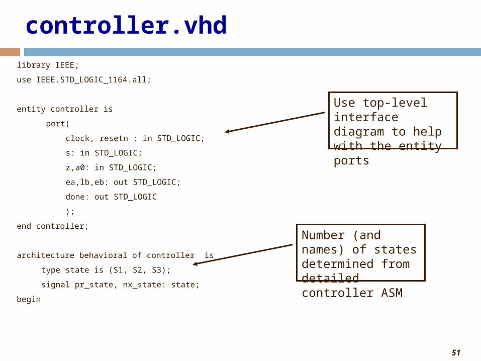
controller.vhd
library IEEE;
use IEEE.STD_LOGIC_1164.all;
entity controller is
port(
clock, resetn : in STD_LOGIC;
s: in STD_LOGIC;
z,a0: in STD_LOGIC;
ea,lb,eb: out STD_LOGIC;
done: out STD_LOGIC
);
end controller;
architecture behavioral of controller is
type state is (S1, S2, S3);
signal pr_state, nx_state: state;
begin
Use top-level interface diagram to help with the entity ports
Number (and names) of states determined from detailed controller ASM

52
controller.vhd cont'd
-- section 1: fsm register
process (resetn,clock)
begin
if (resetn='0') then
pr_state <= S1;
elsif (clock'event and clock='1') then
pr_state <= nx_state;
end if;
end process;
-- section 2: next state function
next_state_function: process (s,z,a0,pr_state)
begin
case pr_state is
when S1 =>
if (s = '0') then
nx_state <= S1;
else
nx_state <= S2;
end if;
Next state is a function of inputs and present state
Inputs in diamonds are used to choose next state

53
controller.vhd cont'd
when S2 =>
if (z = '0') then
nx_state <= S2;
else
nx_state <= S3;
end if;
when S3 =>
if (s = '0') then
nx_state <= S1;
else
nx_state <= S3;
end if;
end case;
end process;

54
controller.vhd cont'd
--section 3: output function
output_function: process (s,z,a0,pr_state)
begin
done <= '0'; ea <= '0'; lb <= '0'; eb <= '0'; -- set all outputs to zero by default
case pr_state is
when S1 =>
lb <= '1';
when S2 =>
ea <= '1'; -- Moore type output before the IF statement
if (z = '0' and a0 = '1') then
eb <= '1'; -- Mealy type output after the IF statement
end if;
when S3 =>
done <= '1';
end case;
end process;
end behavioral;
In general, output is a function of inputs and present state (i.e. both Moore and Mealy)

55
Coding Step 2: Datapath
• Code the datapath based on the datapath block diagram• May have to use structural coding style• First generate building blocks
• Use top-level interface diagram to help with entity input and output PORTS
• All internal wires of the datapath block diagram are SIGNALS in datapath.vhd

56
Datapath Block Diagram
L
E Counter
w
L E
Shift
LB
EBLA
EA
0
Clock
0
B z a 0
Data
n
A
n
log 2 n
log 2 n

57
upcount.vhd
library IEEE;
use IEEE.STD_LOGIC_1164.all;
use IEEE.std_logic_unsigned.all;
entity upcount is
generic (N : integer := 2);
port(
clock : in STD_LOGIC;
l : in STD_LOGIC;
e : in STD_LOGIC;
data_in : in STD_LOGIC_VECTOR(N-1 downto 0);
q : out STD_LOGIC_VECTOR(N-1 downto 0)
);
end upcount;

58
upcount.vhd
architecture behavioral of upcount is
signal qtemp : std_logic_vector(N-1 downto 0);
begin
process(clock)
begin
if (clock'event and clock='1') then
if l = '1' then
qtemp <= data_in;
elsif e = '1' then
qtemp <= qtemp + 1;
end if;
end if;
end process;
q <= qtemp;
end behavioral;

59
shiftrne.vhd
library IEEE;
use IEEE.STD_LOGIC_1164.all;
entity shiftrne is
generic (N : integer := 2);
port(
clock : in STD_LOGIC;
l : in STD_LOGIC;
e : in STD_LOGIC;
w: in STD_LOGIC;
data_in : in STD_LOGIC_VECTOR(N-1 downto 0);
q : out STD_LOGIC_VECTOR(N-1 downto 0)
);
end shiftrne;

60
shiftrne.vhd
architecture behavioral of shiftrne is
signal qtemp: std_logic_vector(N-1 downto 0);
begin
process(clock)
begin
if (clock'event and clock = '1') then
if l = '1' then
qtemp <= data_in ;
elsif e = '1' then
for i in 0 to N-2 loop
qtemp(i) <= qtemp(i+1) ;
end loop ;
qtemp(n-1) <= w ;
end if ;
end if ;
end process ;
q <= qtemp;
end behavioral ;

61
datapath.vhd
library IEEE;
use IEEE.STD_LOGIC_1164.all;
use ieee.std_logic_arith.all;
use ieee.std_logic_unsigned.all;
entity datapath is
generic(N : integer:= 4;
logN: integer:= 2) ;
port(
clock: in STD_LOGIC;
data : in STD_LOGIC_VECTOR(N-1 downto 0);
la: in STD_LOGIC;
ea, lb, eb: in STD_LOGIC;
z: out STD_LOGIC;
a0: out STD_LOGIC;
b: out STD_LOGIC_VECTOR(logN-1 downto 0)
);
end datapath;
Use top-level interface diagram to help with the entity ports
Two generics used

62
datapath.vhd cont'darchitecture behavioral of datapath is
component upcount
generic(
N : INTEGER := 2);
port(
clock : in std_logic;
l : in std_logic;
e : in std_logic;
data_in : in std_logic_vector(N-1 downto 0);
q : out std_logic_vector(N-1 downto 0));
end component;
component shiftrne
generic(
N : INTEGER := 2);
port(
clock : in std_logic;
l : in std_logic;
e : in std_logic;
w : in std_logic;
data_in : in std_logic_vector(N-1 downto 0);
q : out std_logic_vector(N-1 downto 0));
end component;
Component declaration in main code

63
datapath.vhd cont'dsignal A: std_logic_vector(N-1 downto 0); -- internal wires in block diagram are signals
begin
shift1 : shiftrne
generic map(N => N)
port map(
clock => clock, l => la, e => ea,
w => '0', data_in => data, q => a );
count1 : upcount
generic map(N => logN)
port map(
clock => clock, l => lb, e => eb,
data_in => (others => '0'), q => b );
z <= '1' when (conv_integer(unsigned(a)) = 0 ) else '0';
a0 <= a(0);
end behavioral;

64
Step 3: Code top-level entity
• Code top-level entity using specification and top-level entity diagram• All external inputs and outputs to either datapath or controller
should be top-level entity PORTS• All wires between the datapath and controller should be declared
as SIGNALS in the top-level architecture• This step should consist of
• Declaring SIGNALS between datapath and controller• Declaring components datapath and controller (either in main code
or package)• Instantiating datapath.vhd and controller.vhd and making proper
port mapping

65
N
Clock ResetData
B
log2(N)
s
Done
z
a0
EA
LB
EB
datapath.vhd controller.vhd
Top-Level Interface Diagram
LA
66
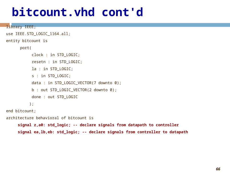
bitcount.vhd cont'dlibrary IEEE;
use IEEE.STD_LOGIC_1164.all;
entity bitcount is
port(
clock : in STD_LOGIC;
resetn : in STD_LOGIC;
la : in STD_LOGIC;
s : in STD_LOGIC;
data : in STD_LOGIC_VECTOR(7 downto 0);
b : out STD_LOGIC_VECTOR(2 downto 0);
done : out STD_LOGIC
);
end bitcount;
architecture behavioral of bitcount is
signal z,a0: std_logic; -- declare signals from datapath to controller
signal ea,lb,eb: std_logic; -- declare signals from controller to datapath

67
bitcount.vhd cont'dcomponent controller
port(
clock : in std_logic;
resetn : in std_logic;
s : in std_logic;
z : in std_logic;
a0 : in std_logic;
ea : out std_logic;
lb : out std_logic;
eb : out std_logic;
done : out std_logic);
end component;
component datapath
generic(
N : INTEGER := 4;
logN : INTEGER := 2);
port(
clock : in std_logic;
data : in std_logic_vector(N-1 downto 0);
la : in std_logic;
Component declaration of controller and datapath in main code. Can also do in package.

68
bitcount.vhd cont'dea : in std_logic;
lb : in std_logic;
eb : in std_logic;
z : out std_logic;
a0 : out std_logic;
b : out std_logic_vector(logN-1 downto 0));
end component;
begin
U1 : controller
port map(
clock => clock,
resetn => resetn,
s => s,
z => z,
a0 => a0,
ea => ea,
lb => lb,
eb => eb,
done => done
);
69
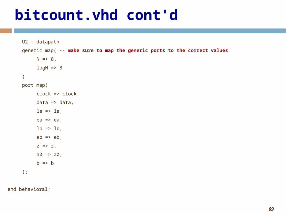
bitcount.vhd cont'd
U2 : datapath
generic map( -- make sure to map the generic ports to the correct values
N => 8,
logN => 3
)
port map(
clock => clock,
data => data,
la => la,
ea => ea,
lb => lb,
eb => eb,
z => z,
a0 => a0,
b => b
);
end behavioral;

70
Complete design
• You just completed your first ASM-based design from beginning to end!
• To summarize, once you get a specification:• Do the five steps to get from specification to "detailed
controller FSM", "datapath block diagram", and "top-level interface diagram"
• Do the three steps to map this into VHDL code• All that is left to do is create a testbench and test the
circuit
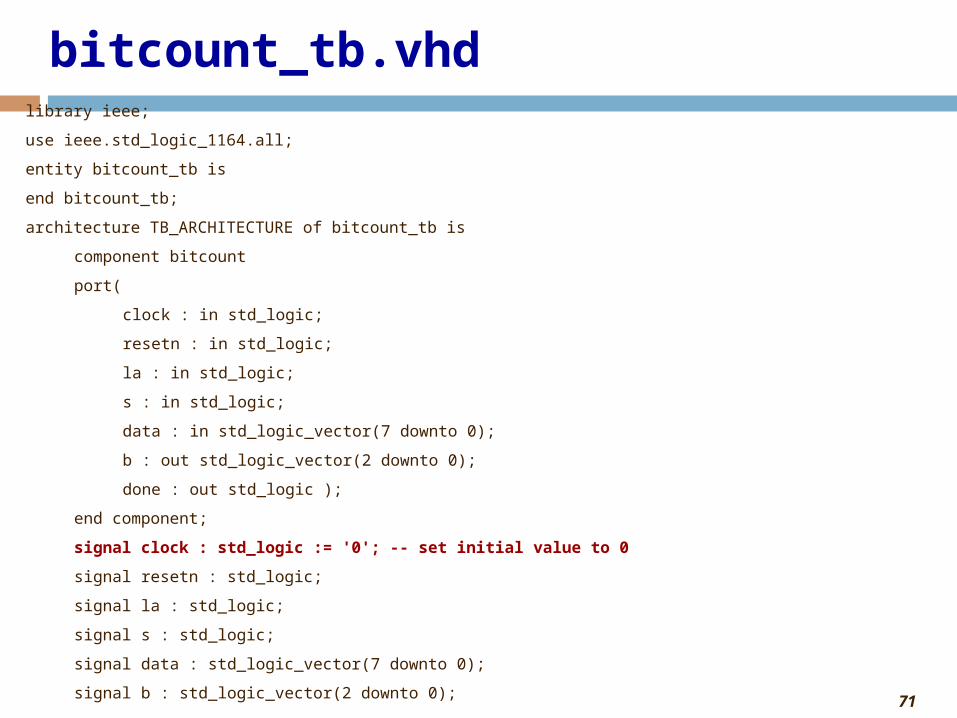
71
bitcount_tb.vhdlibrary ieee;
use ieee.std_logic_1164.all;
entity bitcount_tb is
end bitcount_tb;
architecture TB_ARCHITECTURE of bitcount_tb is
component bitcount
port(
clock : in std_logic;
resetn : in std_logic;
la : in std_logic;
s : in std_logic;
data : in std_logic_vector(7 downto 0);
b : out std_logic_vector(2 downto 0);
done : out std_logic );
end component;
signal clock : std_logic := '0'; -- set initial value to 0
signal resetn : std_logic;
signal la : std_logic;
signal s : std_logic;
signal data : std_logic_vector(7 downto 0);
signal b : std_logic_vector(2 downto 0);

72
bitcount_tb.vhd cont'dsignal done : std_logic;
constant clockperiod : time := 20 ns ;
begin
UUT : bitcount
port map (
clock => clock,
resetn => resetn,
la => la,
s => s,
data => data,
b => b,
done => done
);

73
bitcount_tb.vhd cont'dprocess
begin
s <= '0';
la <= '0';
resetn <= '0'; -- put system in reset
wait until (clock'event and clock='0'); -- negedge of clock
wait for (clockperiod*2); -- wait two more clock cycles
resetn <= '1'; -- deassert reset
wait for clockperiod;
la <= '1'; -- load data into system
data <= "11001101";
wait for clockperiod;
la <= '0';
s <= '1'; -- tell system to begin computation
wait until done='1'; -- wait until done

74
bitcount_tb.vhd cont'dwait until (clock'event and clock='0'); -- negedge of clock
s <= '0';
wait for clockperiod*3;
la <= '1'; -- load data into system
data <= "00010001";
wait for clockperiod;
la <= '0';
s <= '1'; -- tell system to begin computation
wait; -- wait forever
end process;
clock <= NOT clock after (clockperiod/2);
end TB_ARCHITECTURE;

75
Waveform
11001101 has 5 ones 00010001 has 2 ones
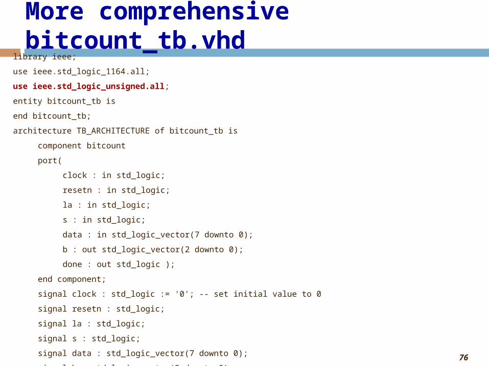
76
More comprehensive bitcount_tb.vhdlibrary ieee;
use ieee.std_logic_1164.all;
use ieee.std_logic_unsigned.all;
entity bitcount_tb is
end bitcount_tb;
architecture TB_ARCHITECTURE of bitcount_tb is
component bitcount
port(
clock : in std_logic;
resetn : in std_logic;
la : in std_logic;
s : in std_logic;
data : in std_logic_vector(7 downto 0);
b : out std_logic_vector(2 downto 0);
done : out std_logic );
end component;
signal clock : std_logic := '0'; -- set initial value to 0
signal resetn : std_logic;
signal la : std_logic;
signal s : std_logic;
signal data : std_logic_vector(7 downto 0);
signal b : std_logic_vector(2 downto 0);

77
More comprehensive bitcount_tb.vhdsignal done : std_logic;
constant clockperiod : time := 20 ns ;
begin
UUT : bitcount
port map (
clock => clock,
resetn => resetn,
la => la,
s => s,
data => data,
b => b,
done => done
);

78
More comprehensive bitcount_tb.vhdprocess
begin
s <= '0';
la <= '0';
resetn <= '0'; -- put system in reset
wait until (clock'event and clock='0'); -- negedge of clock
wait for (clockperiod*2); -- wait two more clock cycles
resetn <= '1'; -- deassert reset
wait for clockperiod;
la <= '1'; -- load data into system
data <= "00000000";
wait for clockperiod;
la <= '0';
s <= '1'; -- tell system to begin computation
wait until done='1'; -- wait until done

79
More comprehensive bitcount_tb.vhdfor i in 1 to 254 loop -- assume all 1's not possible
wait until (clock'event and clock='0'); -- negedge of clock
s <= '0';
wait for clockperiod*3;
la <= '1'; -- load data into system
data <= data+1;
wait for clockperiod;
la <= '0';
s <= '1'; -- tell system to begin computation
wait until done='1';
end loop;
wait; -- wait forever
end process;
clock <= NOT clock after (clockperiod/2);
end TB_ARCHITECTURE;
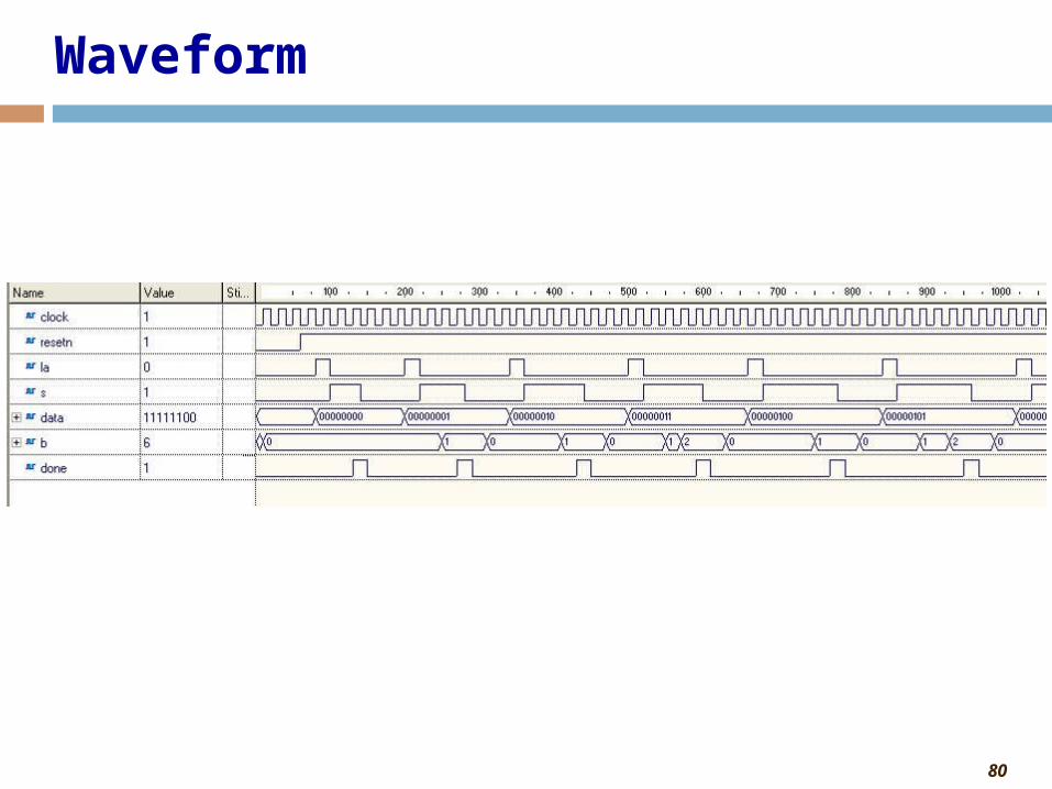
80
Waveform