1 AC500 System - A-Laba-lab.ee/.../courses/ISS0065/2014_Autumn/materials/PLC_1_0.pdf · 2014 PLC 1...
18
2014 PLC 1 AC500 System The following electronic modules are the basic components of the AC500 system: • CPUs of different performance classes • Communication Modules for various bus systems, e.g. PROFIBUS R , CANopen R , DeviceNet TM , PROFINET R , EtherCAT R Central expansion: One CPU supports direct connection of up to seven S500 FBP system I/O devices. Decentralized expansion: Using the DC505 FBP interface module (for fieldbus systems PROFIBUS R DP, CANopen R , DeviceNet TM , Modbus RTU), up to seven S500 FBP system I/O devices can be connected (with a maximum of four analog modules). General structure of PLC provided in the Lab CPU PM573 (512kB, 2 RS-232/485 interfaces - programming, Modbus/CS31 (COM1), 1 x FBP) with an integrated Ethernet Communication Module (TCP/IP). The I/O Modules Digital and analog in different versions. Can be simply plugged onto the terminal units – for local expansion of the CPU (max. 10 modules). Communication Modules Communication Module for fieldbus systems - PROFIBUS R DP, DeviceNet TM and CANopen R . K.Vassiljeva 1 ISS0065 Control Instrumentation
Transcript of 1 AC500 System - A-Laba-lab.ee/.../courses/ISS0065/2014_Autumn/materials/PLC_1_0.pdf · 2014 PLC 1...

2014 PLC
1 AC500 System
The following electronic modules are the basic components of the AC500 system:
• CPUs of different performance classes
• Communication Modules for various bus systems, e.g. PROFIBUS R©, CANopen R©, DeviceNetTM,PROFINET R©, EtherCAT R©
Central expansion: One CPU supports direct connection of up to seven S500 FBP system I/Odevices.
Decentralized expansion: Using the DC505 FBP interface module (for fieldbus systems PROFIBUS R©DP, CANopen R©, DeviceNetTM, Modbus RTU), up to seven S500 FBP system I/O devices can beconnected (with a maximum of four analog modules).
General structure of PLC provided in the Lab
CPU PM573 (512kB, 2 RS-232/485 interfaces - programming, Modbus/CS31 (COM1), 1 x FBP)with an integrated Ethernet Communication Module (TCP/IP).
The I/O Modules Digital and analog in different versions. Can be simply plugged onto theterminal units – for local expansion of the CPU (max. 10 modules).
Communication Modules Communication Module for fieldbus systems - PROFIBUS R© DP,DeviceNetTM and CANopen R©.
K.Vassiljeva 1 ISS0065 Control Instrumentation

PLC 2014
AC500 Control Builder provides the following functionalities:
• Five standardized programming languages: Function Block Diagram (FBD), Instruction List(IL), Ladder Diagram (LD), Structured Text (ST), Sequential Function Chart (SFC);
• Free graphical function chart (CFC);
• Debugging functions for the program test: Single step, Single cycle, Breakpoint.
IEC 61131-3 commands can be simulated without a PLC being connected, including the relevantmalfunctions. After the program test, the application can be downloaded to the control system.
2 Introduction to the program environment
2.1 Declaration of the Modules
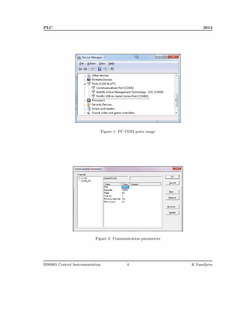
In order to communicate with PLC via COM2 we need to know the number of com port used inPC. In Device Manager check the Ports (COM & LTP). Find out what port is used for ProlificUSB-to-Serial.
Start "ABB Control Builder Plus". This is an environment to connect ABB controller withCoDeSys Programming System.
Then program starts you will see the recent projects. If you want to start your own project -you should choose the right configuration of the controller.
Choose AC500 PM573-ETH V2.1. Choose the name of your project and location where itwill be saved.
To avoid some error messages
Battery Click on CPU_parameters and open the CPU Parameters Configuration window: Checkbattery–value = OFF.
Fault Configuration Double click on Interfaces → COM2_Online and set Run on Config Fault–value=YES.
DA501
In the Devices Window declare the right I/O module
• Click with right button on IO_Bus(I/O-Bus) and choose Add Devices.
• In the new window in the tree S500-I/O modules choose DA501.
Double click on the DA501 opens the window DA501 Configuration. Set the next parameters:
• Input 0, channel configuration–value="0...10/ V"
ISS0065 Control Instrumentation 2 K.Vassiljeva

2014 PLC
• Input 1, channel configuration–value="0...10/ V"
• Input 2, channel configuration–value="Pt100(2-wire/ −50 . . .+ 70/◦C)"
• Output 0, channel configuration–value="−10 . . .+ 10/V "
• Output 1, channel configuration–value="−10 . . .+ 10/V "
On order to use Global Variable Names as names of module physical outputs, mapping is needed.Open the DA501 I/O Mapping window.
• As first digital inputs (%IX0.0–%IX0.7) are connected to the switches S0-S7, create the samevariable.
• Digital inputs %IX1.0–%IX1.7, name variables according to the rules of the company. Forexample: m2_DI_8, where "m2" is the module position on the BUS, "DI"–Digital Input and"8"–position of the input.
• Analog Inputs %IW1–%IW4.
• Analog Outputs %QW0–%QW1.
• Digital Inputs %IX10.0–%IX10.7.
• Digital Outputs %QX6.0–%QX6.7.
Now you can start program the PLC. In the Devices tree double click on AC500– CoDeSysprogramming environment will run.
NB! Every time you need to open previously saved CoDeSys project you must do itthrough ABB Control Builder Plus.
2.2 Communication
To download your programs to the controller you need set the connection.In menu Online→Communication Parameters....Add new Connection:
• Choose Serial (RS232);
• Name it: ComN_PC, where N is the number of COM port (see Fig. 1);
• Set the right parameters for communication via COM2 (see Fig. 2).
K.Vassiljeva 3 ISS0065 Control Instrumentation
PLC 2014
Figure 1: PC COM ports usage
Figure 2: Communication parameters
ISS0065 Control Instrumentation 4 K.Vassiljeva

2014 PLC
2.3 First Steps
POU (Program Organization Unit). Functions, function blocks, and programs are POUs which canbe supplemented by actions.
Each POU consists of a declaration part and a body. The body is written in one of the IECprogramming languages which include IL, ST, SFC, FBD, LD or CFC. CoDeSys supports all IECstandard POUs.
In this course we are interested get to know Structured Text (ST). The Structured Text consistsof a series of instructions which, as determined in high level languages.
Attention: Do not delete or rename the POU PLC_PRG (assuming you are not using a TaskConfiguration)! PLC_PRG is generally the main program in a single task program.
Monitoring
In Online mode, all displayable variables are read from the controller and displayed in real time. Youwill find this display in the declarations and program editor; you can also read out current valuesof variables in the watch and receipt manager and in a visualization. If variables from instances offunction blocks are to be monitored, the corresponding instance must first be opened.
Simulation
During the simulation the created PLC program is not processed in the PLC, but rather in thecalculator on which CoDeSys is running. All online functions are available. That allows you to testthe logical correctness of your program without PLC hardware.
NB! As PLC does not have installed battery all the information downloaded to thecontroller will be lost when it is turned off.
2.4 Project
The following objects are included in a project: POUs, data types, visualizations, resources.Select the entry PLC-Browser in the Resources tab-control(bottom left corner). The browser
consists of a command entry line and a result/display window. In a selection box the input linedisplays a list of all the commands entered since the start of the project (input history) or allpossible commands here (. . .).
Click on three dots (right top corner) and open "Insert standard command". Select
• diagshow all in order to see all error messages;
• diagreset - to delete them from PLC.
The entered command is sent to the controller with <Enter>. If there is no Online connection,the command is displayed in the result window in the same way as it is sent to the controller,
K.Vassiljeva 5 ISS0065 Control Instrumentation
PLC 2014
otherwise the response from the controller is shown there. If a new command is sent to the controller,the content of the result window is deleted.
3 Binary variables
Value of the binary variable can be presented by: 1/0, ON/OFF, True/False.
Exercise 1 Working with (physical) Global Variables
In order to check what functions, blocks, variables and operations are available, you need to callInput Assistant. Press F2 button.
In Global Variables
• select any input address (S0-S7);
• select any digital output variable.
your_output := your_input;
Download program to the controller
• in Online menu select Login or ALT+F8;
• to Start program it should be in running mode: in Online menu select Run or F5.
If Program is not running (you cannot switch on Running mode), please see Section 2.4 and reseterror messages. Check the results using physical inputs of the PLC.
Exercise 2 Combinatory logic
Realize two logical functions F = A ∨ B&C and W = (A ∨ B)&C there logical operations aredenoted as & -"AND" and ∨ - "OR".Select any digital inputs (S0-S7) as A,B,C, and observable digital outputs: F,W
Exercise 3 Majority rule
If you would like to comment your previous code, write it in (* commented code *).Combine circuit of 3 inputs and one output: output is "ON" if at least two inputs are "ON".
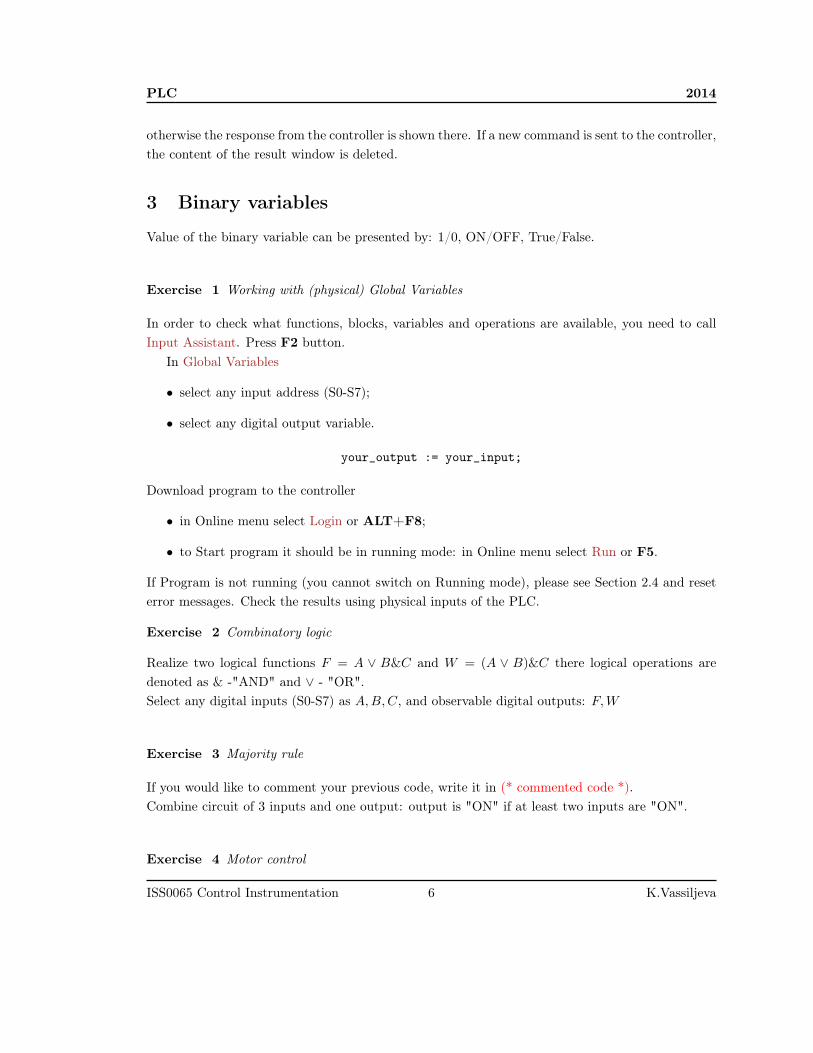
Exercise 4 Motor control
ISS0065 Control Instrumentation 6 K.Vassiljeva
2014 PLC
START and STOP input signals turn on and off signals of the motor.
Select the controller inputs and outputs, tag them:
START, STOP and Motor.Write a program. Run program on PLC.
4 Timers
Types of the Timers
• TP - Timer is a trigger;
• TON - Timer On Delay;
• TOF - Turn-Off Delay.
All timers have the following parameters:
• IN - input which starts the timer (BOOL type);
• PT(Preset Time) - (TIME type) variable;
• Q - state of the timer (BOOL type);
• ET - countering time (TIME type).
See correct assignment of TIME constants in help files of CoDeSys.In order to use timer you need to declare it as one of the types described above.
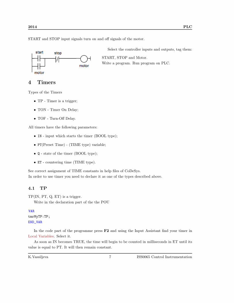
4.1 TP
TP(IN, PT, Q, ET) is a trigger.Write in the declaration part of the the POU
VARtmrMyTP:TP;END_VAR
In the code part of the programme press F2 and using the Input Assistant find your timer inLocal Variables. Select it.
As soon as IN becomes TRUE, the time will begin to be counted in milliseconds in ET until itsvalue is equal to PT. It will then remain constant.
K.Vassiljeva 7 ISS0065 Control Instrumentation

PLC 2014
IN
Q
ET
t0 t1
t0
t0
t0+PT
t1
t2 t3
t2+PT
t2
t2
t4
t4
t4
t5
t4+PT
t5
0
1
Figure 3: Graphic Display of the TP Time Sequence
Q is TRUE as from IN has got TRUE and ET is less than or equal to PT. Otherwise it isFALSE.
Q returns a signal for the time period given in PT.
First, declare new variables in declaration parttrigUp: BOOL;
tTP_Val: TIME;In the coding part set the next parameterstmrMyTP(IN:=your_input, PT:=T#5s, Q=>trigUp, ET=>tTP_Val);
your_output :=trigUP;Download program to the PLC.
4.2 TON
TON(IN, PT, Q, ET) implements a turn-on delay.Write in the declaration part of the the POU
VARtmrMyTON:TON;END_VAR
As soon as IN becomes TRUE, the time will begin to be counted in milliseconds in ET until itsvalue is equal to PT. It will then remain constant.
Q is TRUE when IN is TRUE and ET is equal to PT. Otherwise it is FALSE.Thus, Q has a rising edge when the time indicated in PT in milliseconds has run out.
4.3 TOF
TOF(IN, PT, Q, ET) implements a turn-off delay.
ISS0065 Control Instrumentation 8 K.Vassiljeva

2014 PLC
IN
Q
ET
t0 t1
t1
t0
t0+PT
t1
t2 t3
t2 t3
t4
t4
t5
t4+PT
t5
0
1
t5
Figure 4: Graphic Display of the TON Time Sequence
VARtmrMyTOF:TOF;END_VAR
IN
Q
ET
t0 t1
t0 t1+PT
t1
t2 t3
t2 t3
t4
t4
t5
t5+PT
t5
0
1
t2
Figure 5: Graphic Display of the TOF Time Sequence
As soon as IN becomes FALSE, in ET the time will begin to be counted in milliseconds in ETuntil its value is equal to PT. It will then remain constant.
Q is FALSE when IN is FALSE and ET equal PT. Otherwise it is TRUE.Thus, Q has a falling edge when the time indicated in PT in milliseconds has run out.
Exercise 5 Set time on 7 s. delay
Read the HELP for the Timers. Start timer with a switch input. Use a timer. Add a physicaloutput, which would indicate the timer output signal (output of the controller).
• Check timer’s work switching an input signal and tracking the output of the controller.
• Observe output of the timer and the running time /Monitoring mode/.
K.Vassiljeva 9 ISS0065 Control Instrumentation
PLC 2014
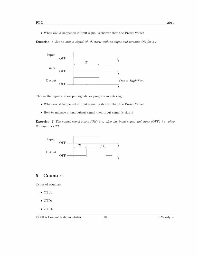
• What would happened if input signal is shorter than the Preset Value?
Exercise 6 Set an output signal which starts with an input and remains ON for 4 s.
tOFF
tOFF
tOFF
T
Input
Timer
Output Out = Inp&Tim
Choose the input and output signals for program monitoring.
• What would happened if input signal is shorter than the Preset Value?
• How to manage a long output signal then input signal is short?
Exercise 7 The output signal starts (ON) 2 s. after the input signal and stops (OFF) 1 s. afterthe input is OFF.
tOFF
tOFF
T1 T2
Input
Output
5 Counters
Types of counters:
• CTU;
• CTD;
• CTUD.
ISS0065 Control Instrumentation 10 K.Vassiljeva
2014 PLC
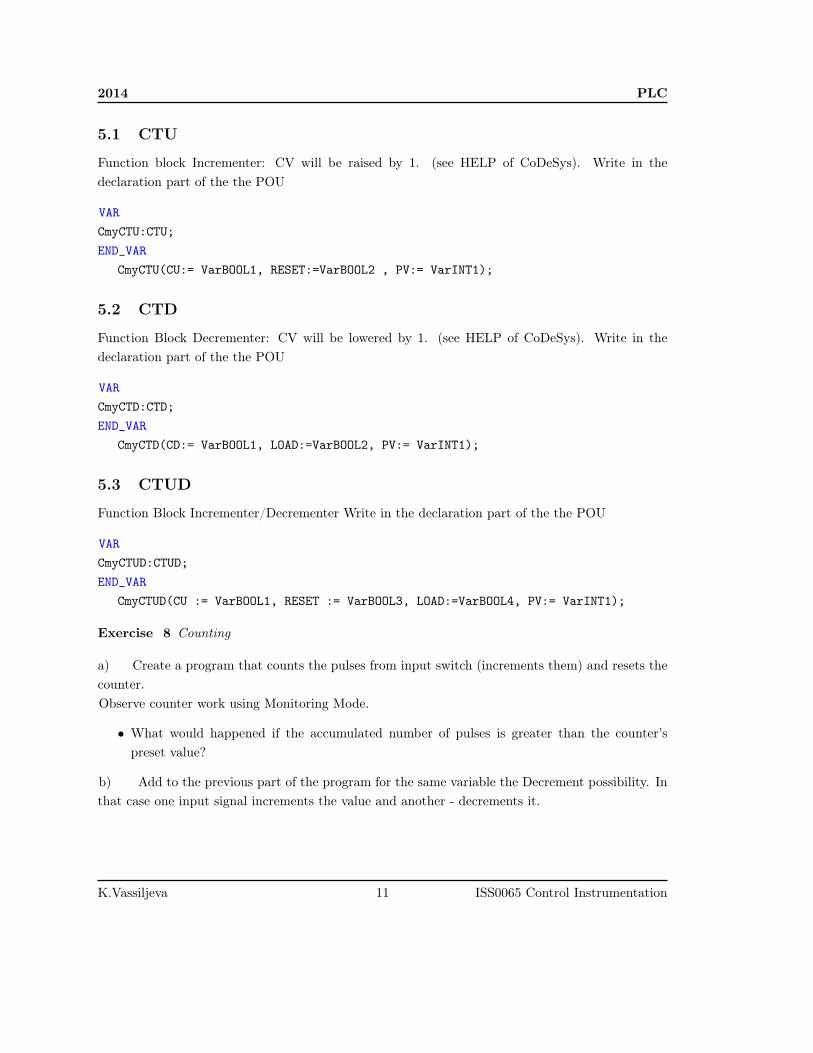
5.1 CTU
Function block Incrementer: CV will be raised by 1. (see HELP of CoDeSys). Write in thedeclaration part of the the POU
VARCmyCTU:CTU;END_VAR
CmyCTU(CU:= VarBOOL1, RESET:=VarBOOL2 , PV:= VarINT1);
5.2 CTD
Function Block Decrementer: CV will be lowered by 1. (see HELP of CoDeSys). Write in thedeclaration part of the the POU
VARCmyCTD:CTD;END_VAR
CmyCTD(CD:= VarBOOL1, LOAD:=VarBOOL2, PV:= VarINT1);
5.3 CTUD
Function Block Incrementer/Decrementer Write in the declaration part of the the POU
VARCmyCTUD:CTUD;END_VAR
CmyCTUD(CU := VarBOOL1, RESET := VarBOOL3, LOAD:=VarBOOL4, PV:= VarINT1);
Exercise 8 Counting
a) Create a program that counts the pulses from input switch (increments them) and resets thecounter.Observe counter work using Monitoring Mode.
• What would happened if the accumulated number of pulses is greater than the counter’spreset value?
b) Add to the previous part of the program for the same variable the Decrement possibility. Inthat case one input signal increments the value and another - decrements it.
K.Vassiljeva 11 ISS0065 Control Instrumentation

PLC 2014
Exercise 9 Wrapping Machine
PLC
BOX
QP
OUT
product
Figure 6: Wrapping Machine
Pieces product (bottles) come off the production line, they are countered by the sensor QP (seeFig. 6).
Then you have 9 pieces of the product the output OUT is launched for the 2 s., which stops theproduction line and puts the product into the box.
Simulate a delivery of the product by the signal 1 Hz (use function block BLINK).
The function block BLINK generates a pulsating signal. Write in the declaration part of thethe POU
VARbottle: BLINK;END_VAR
bottle(ENABLE:=_, TIMELOW:=t#1s, TIMEHIGH:=t#1s, OUT=>_ );
Write a program.
Exercise 10 Operations with numeric data
ISS0065 Control Instrumentation 12 K.Vassiljeva

2014 PLC
1. Set a constant value 5 to variable A and 2 to variable B
2. Counter (C) counts the number of impulses from Inp module (%IX._)
3. D = A+C; E = B*D;
Compare E with constant 18. Results of comparison present as binary signal (<,=,>). Add Inputsthat reset C, D and E values.
6 HMI
A visualization is a graphical representation of the project variables which allows inputs to the PLCprogram in online mode via mouse and keypad. The CoDeSys visualization editor, which is part ofthe programming system provides graphic elements which can be arranged as desired and can beconnected with project variables.
The visualization which is created in the programming system will in many cases be used asthe only user interface available for controlling and watching the associated PLC program in onlinemode. For this purpose it must be possible to give inputs to the program solely by activatingvisualization elements.
A visualization created in CoDeSys can later be used in different ways:
• It can be made available on CoDeSys HMI, a special runtime system for operating the visu-alization in full screen mode on a PLC computer.
• It can be made available as a Web-Visualization, which allows to call and operate it via theInternet (useful for remote maintenance purposes).
• It can be made available as a Target-Visualization, which can be started directly on the PLC.
When defining the name of the visualization object, please regard the following:
1. A visualization named "PLC_VISU" per default automatically will be used as start visualiza-tion in a Target- or Web-Visualization resp. In CoDeSys HMI, if there not explicitly anothervisualization is configured for this.
2. A visualization may not get the same name as another object within the project because thiswould result in problems when changing between visualizations.
For your first visualization select Visualizations tab - Right button click on Visualizations folder- Add Object. In New Visualization window type "PLC_VISU" (see Fig. 7).
K.Vassiljeva 13 ISS0065 Control Instrumentation

PLC 2014
Figure 7: New Visualization creation
6.1 Visualization Elements
A visualization element is a graphical element, which is used to fill a visualization object. Theavailable elements are offered in the CoDeSys menu bar. Each element gets a separate configuration.
Go to the ’Insert’ menu item and select freely from the following commands(see Fig. 8): ’Rect-angle’, ’Rounded Rectangle’, ’Ellipse’, ’Polygon’
’Polyline’, ’Curve’, ’Pie’, ’Bitmap’, ’Visualization’,
’Button’, ’Table’, ’ActiveX-Element’, ’Scrollbar’, ’Meter’, ’Bar Display’, ’Histogram’, ’Alarm table’,’Trend’, ’WMF file’.
Figure 8: New Visualization creation
ISS0065 Control Instrumentation 14 K.Vassiljeva

2014 PLC
Text
Select ’Rectangle’ from the menu and then using arrow set the area where text should be placed.Double clicking on the object opens the window Regular Element Configuration (#N). In thiswindow you can set different parameters of the object.
• In the Text Category type the Application Name: "Bottles packing line". Select suitable fontand its size.
• In Colors Category choose color of the Rectangle and its border.
Final view of the application provided further in Fig. 9.
Figure 9: Visualization of the Wrapping Machine exercise
Buttons
Select ’Button’ from the menu then using arrow set the area where button should be placed. Add2 buttons which STARTs and STOPs the line.
For example for START button set the next parameters:
• Type "START" in the Text Category.
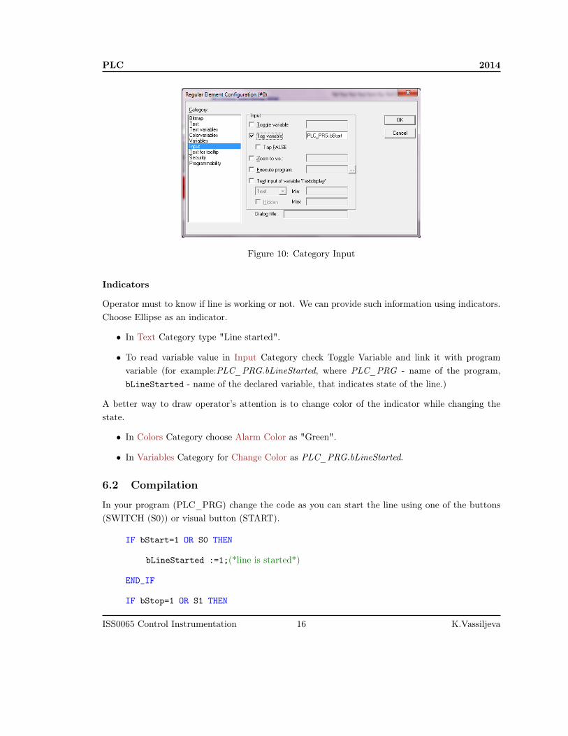
• In Input Category select Tap Variable (see Fig. 10).
• To link main program variable with a button type PLC_PRG.bStart, where PLC_PRG -name of the program, bStart - name of the declared variable, that starts the line.
Do the same way for the STOP button. Set button color as "Red" in Bitmap Category.
K.Vassiljeva 15 ISS0065 Control Instrumentation
PLC 2014
Figure 10: Category Input
Indicators
Operator must to know if line is working or not. We can provide such information using indicators.Choose Ellipse as an indicator.
• In Text Category type "Line started".
• To read variable value in Input Category check Toggle Variable and link it with programvariable (for example:PLC_PRG.bLineStarted, where PLC_PRG - name of the program,bLineStarted - name of the declared variable, that indicates state of the line.)
A better way to draw operator’s attention is to change color of the indicator while changing thestate.
• In Colors Category choose Alarm Color as "Green".
• In Variables Category for Change Color as PLC_PRG.bLineStarted.
6.2 Compilation
In your program (PLC_PRG) change the code as you can start the line using one of the buttons(SWITCH (S0)) or visual button (START).
IF bStart=1 OR S0 THEN
bLineStarted :=1;(*line is started*)
END_IF
IF bStop=1 OR S1 THEN
ISS0065 Control Instrumentation 16 K.Vassiljeva

2014 PLC
bLineStarted :=0; (*line is stopped*)
END_IF
Where bStart,bStop,bLineStarted are BOOL type variables.Download program to the PLC. While running open visualization tab. Check how it works
• Does click on the START button or turn on switch S0 start the line?
• Does indicator change its color while switching the line?
6.3 Other elements
Provide the following information to the operator:
• Using ’Meter’ show how many bottles from 9 possible are in the box.
• Also use text to provide that information numerically (see help: Visualization, ConfigureText).
In Variables Category set variable which shows bottle index in the box (for example: PLC_PRG.wBottleNum)to the Textdisplay.
Motion
Add one more ’Rectangle’. In order to show sent out packed box, the x-axis coordinates should bechanged. In Motions Absolute enter x_offset variable. This variable can shift the element in theX direction, depending on the respective variable value.
NB! Do not forget to calculate new value of the x_offset in your program.
IF bPacking THEN
x_offSet:= x_offSet + 1;(*new position of the box*)
IF x_offSet = 250 THEN (*where 250 is the right edge of apps window*)
x_offSet:= 0; (*initial position of the box if window edge is reached*)
END_IF
ELSE
x_offSet:= 0; (*initial position of the box if not packing*)
END_IF
Below the box provide information how many boxes have been packed.
K.Vassiljeva 17 ISS0065 Control Instrumentation

PLC 2014
Time
Open PLC-Browser window. Type time command. You can see that time variable has been reset.Set the right time to you PLC.
1. date 2014-mm-dd,
2. time HH:MM:SS.
Now, that information can be provided by your application.First of all declare the following variables
• tTnD:SystemTimeDate;
Local system clock Date and Time information can be read. On the visual part of you applicationadd one more ’Rectangle’.
If you enter "%t", followed by a certain sequence of special placeholders, then this location willbe replaced in Online mode by the system time. The placeholders define the display format, seethe following table. See help file: Text.
Attention: Do not insert any other characters before %t in the ’Content’ field.
Examples:
1. %t%a %b %d.%m.%y %H:%M:%S
• → Displays in online mode: Wed Aug 28.08.02 16:32:45
2. Between the placeholders you can insert any text strings:
• %Today is %d.%m.%y
• → Displays in online mode: Today is 28.08.02
In a Text Category set right placeholders in order to provide information
• Day of the week;
• Date;
• Time;
In Variables Category set the same placeholders for time representation in Textdisplay.In Input Category link corresponding variable in Toggle variable as PLC_PRG.tTnD.
Additional example provided by ABB can be seen: ABB AC500 PLC First Visualization
ISS0065 Control Instrumentation 18 K.Vassiljeva