Voltage Harmonics Measuring Issues in Medium Voltage Systems
Upload
jandfor-tansfg-errottCategory
view
16download
0
A Phase Detection Method for Harmonics and Unbalanced Voltage
Tomonobu Senjyu1, Yuri Yonaha1, Norihiro Nakasone1, Atsushi Yona1, and Chul-Hwan Kim2
1 Department of Electrical and Electronics Engineering, University of the Ryukyu, Nakagami, 903-0213, Japan 2 School of Electric and Computer Engineering, Sungkyunkwan University, Suwon City, 440-746, Korea
Abstract-This paper proposes a phase detection method for
harmonics and unbalanced voltage conditions. The proposed method uses harmonics and unbalanced voltage compensation circuit in addition to basic PLL (Phase Locked Loop) circuit. In the harmonic compensation circuit, the harmonic voltage components are eliminated from the input voltages using specific harmonic detection method. Besides, frequency information of power system used in the specific harmonic detection method is estimated by an extended complex Kalmen filter. In the unbalanced voltage compensation circuit, the input voltage is normalized after the calculated positive sequence component. By means of the proposed method, excellent phase detection performance can be achieved under harmonics and unbalanced voltage conditions. Moreover, detection of positive sequence voltage component becomes possible under voltage drop conditions due to faults in power systems. The effectiveness of the proposed method is verified by simulation results.
I. INTRODUCTION In recent year, with progresses of the power electronics
technology, development and the introduction of power converter to power system are of great interest. When power converter is connected with power system, it is important to synchronize with phase of the output voltage of power system. Besides, exact phase information of the system voltage is also essential for distributed generation, FACTS (Flexible AC Transmission System), and storage system since these equipments use detected phase of positive sequence component of the system voltage.
PLL method for detecting phase of positive sequence component of the input voltage and zero-crossing method for detecting phase by zero cross interval of the voltage are proposed as phase detection method of the system voltage in [1]-[3]. Specifically, PLL method is robust for frequency fluctuation in the power system and can continuously detect phase of the system voltage. However, since these phase detection method, are vulnerable to voltage sag and unbalanced voltage at the time of system fault, and abnormal voltage at the time of harmonic superposition, excellent resistance to abnormal voltage is needed.
PLL method with decoupling network by dual synchronous coordinate is described in [4]. This method achieves good phase detection when system voltage is unbalanced and harmonic superposit ion is occurred. However, phase following
Fig. 1. Basic block diagram of PLL.
characteristic gets worse due to depression of fast response capability by filter in loop circuit and voltage sag at the time of system fault.
This paper proposes a PLL circuit which can detect phase of system voltage quickly. The proposed PLL circuit consists of harmonics elimination circuit and unbalanced voltage compensation circuit. The harmonics elimination circuit mainly focuses on fifth and seventh harmonics included in commercial power source, and detects fundamental wave component by using specific harmonic detection method that eliminates each of the harmonic components. The frequency information of input voltage used for the specific harmonic detection method applies a frequency estimation method based on an extended complex Kalman filter. In the unbalanced voltage compensation circuit, the input voltage is normalized after the calculation of positive sequence component. By means of the proposed method, good phase detection performance can be achieved under harmonics and unbalanced voltage conditions, and detecting positive sequence voltage component with constant amplitude becomes possible under voltage drop conditions due to faults in power systems. The effectiveness of the proposed methods is validated by simulation results using MATLAB.
II. CONVENTIONAL PLL
A. Basic PLL The basic PLL circuit is shown in Fig. 1. The system voltage
inputs are transformed to rotating coordinate system using dq transform. Then, synchronization of the phase is possible by controlling q axis voltage to 0. Here, d axis component indicates magnitude of the system voltage.
B. DDSRF-PLL DDSRF-PLL (Decoupled Double Synchronous Reference
Frame PLL) was proposed in [4]. If input voltage is unbalanced and has harmonics, DDSRF-PLL can achieve high precision to detect a phase. This PLL has decoupling network which revolve
1101

to positive and negative sequence. The rotating coordinate axis for positive and negative sequence components are indicated as dq+1 and dq-1, respectively. Assuming that a PLL can have complete synchronization, a voltage vector with fundamental frequency ω is expressed as following:
( )
( )( ) ( ) ( )
( )
( ) ( )( ) )1(2cos2sin
sin
2sin2cos
cossincos
11
111
11
1
1
1
⎥⎦
⎤⎢⎣
⎡+
⎥⎦
⎤⎢⎣
⎡−
+⎥⎦
⎤⎢⎣
⎡=
⎥⎥⎦
⎤
⎢⎢⎣
⎡=
−−
−−+
++
+
+
+
tt
V
tt
VV
vv
v
t
tt
tq
tddqt
ωω
φ
ωω
φφφ
( )
( )( ) ( ) ( )
( )
( ) ( )( ) )2(
.2cos2sin
sin
2sin2cos
cossincos
11
111
11
1
1
1
⎥⎦
⎤⎢⎣
⎡−+
⎥⎦
⎤⎢⎣
⎡+⎥
⎦
⎤⎢⎣
⎡=
⎥⎥⎦
⎤
⎢⎢⎣
⎡=
++
++−
−−
−
−
−
tt
V
tt
VV
vv
v
t
tt
tq
tddqt
ωω
φ
ωω
φφφ
The above equations suggest that voltage component of dq+1 and dq-1 axis interfere with each another. Oscillating component in (1) and (2) are eliminated by decoupling. Therefore, even if input voltage is unbalanced and has harmonics, high precision phase detection of positive sequence is accomplished. On the other hand, using DDSRF-PLL, the fast response capability is depressed by low pass filter (LPF) which is used for elimination of high frequency and oscillating component of dq axis voltage for harmonics.
III. COMPENSATION FOR HARMONIC
A. Design of harmonics elimination circuit For a harmonic detection method, compared to
comprehensive harmonic detection method which detect all harmonic components, specific harmonic detection method which detects harmonic with respect to each order and also has stability performance is reported in [5]. This paper focuses on the fifth and seventh harmonics which are mostly included in commercial power source, and adopts specific harmonic detection method for harmonic elimination circuit. The block diagram of specific harmonic detection is shown in Fig. 2. Here, input voltage coordinates are transformed using the seventh frequency, and seventh harmonic is extracted by low pass filter (LPF). Transfer function of a seventh harmonic detection circuit using rotating coordinate transform and LPF is given in the following equation:
)3()(1
1)(7
7 ωjsTsG
hh −+
=
where, cfhT π2
1= , ω7:seventh harmonic angular frequency, fc:
cutoff frequency of harmonic detection filter. A harmonic elimination circuit of specific harmonic detection
of Fig. 2 is shown in Fig. 3. First of all, fundamental component is eliminated from vt. Fundamental component vf of input
Fig. 2. Block diagram of the specific 7th-harmonic detection method.
Fig. 3. Harmonic elimination circuit.
voltage vt is detected by Gf (s). Secondly, each order specific harmonic voltage vhn are detected by specific harmonic detection filter Ghn(s). Finally, elimination of harmonic component is achieved by eliminating vhn from vt, and vt’ is obtained.
B. Frequency Estimation by Extended Complex Kalman Filter The harmonic elimination circuit used here needs frequency
information of the system voltage when it uses coordinate transformation. In actual power system, the system frequency oscillation may be caused by introduction of distributed generation or by line fault. If frequency information used in harmonic elimination circuit is not accurate, desired harmonic elimination performance cannot be obtained when there are frequency fluctuations. In this study, a frequency estimation method using extended complex Kalman filter is employed as frequency estimation method [7], [8]. This method is able to estimate frequency instantaneously and exactly when input voltage has noise and harmonic. The system frequency estimation method using extended complex Kalman filter is described below.
The discretized three phase voltage of the power system can be expressed as follows:
( )( )( )
)4(
)(3/2sin)(
)(3/2sin)(
)(sin)(
⎪⎪⎭
⎪⎪⎬
⎫
+++Δ=
+−+Δ=
++Δ=
kTkVkv
kTkVkv
kTkVkv
cmc
bmb
ama
ηπφω
ηπφω
ηφω
where, va, vb, vc are the each phase voltage, Vm is the amplitude of three phase voltage, k is the sampling point, ΔT is the sampling interval, ηa(k), ηb(k), ηc(k) are noise. The discrete voltage signal given in (4), is transformed to αβ coordinate by the following:
)5(.)(
)()(
0
1
32
)()(
23
23
21
21
⎥⎥⎥
⎦
⎤
⎢⎢⎢
⎣
⎡
⎥⎥⎦
⎤
⎢⎢⎣
⎡
−
−−=⎥
⎦
⎤⎢⎣
⎡
kvkvkv
kvkv
c
b
a
β
α
From (5), a discrete complex signal v(k) is given by following
1102

equation:
)6()(
)()()()( kAe
kjvkvkvTkj ηφω
βα
+=
+=+Δ
where, A is the amplitude of transformed complex signal, η is noise.
A discrete observed signal v(k) can be expressed is state space as below:
( )( ) )7(
)()(
)(001
11
2
1
12
1⎥⎦
⎤⎢⎣
⎡⎥⎦
⎤⎢⎣
⎡=⎥
⎦
⎤⎢⎣
⎡++
kxkx
kxkxkx
[ ] )8()()()(
10)()(2
1 kkxkx
kvky η+⎥⎦
⎤⎢⎣
⎡==
where, the states x1, x2 are represented by the following equations:
)9(
.)(
sincos
)(
2
1
⎪⎪⎭
⎪⎪⎬
⎫
=
Δ+Δ=
=
+Δ
Δ
φω
ω
ωωTkj
Tkj
Aekx
TkjTk
ekx
The following nonlinear systems are obtained by the above equations:
( ) ( )( ))10(
)()()(
1
⎪⎭
⎪⎬⎫
+=
=+
kkHxky
kxFkx
η
where, [ ]
( )( ) [ ][ ]
)11(
.10
)()()(
)()()(
211
21
⎪⎪⎭
⎪⎪⎬
⎫
=
=
=
H
kxkxkxkxF
kxkxkxT
T
A extended complex Kalman filter applied to a nonlinear system is shown in (10). The extended complex Kalman filter is one where complex Kalman filter is extended for nonlinear system. Extended Kalman filter algorithm is given below:
( ) ( ) ( ) ( ) ( )( )( ) ( )( )
[ ]( ) ( ) ( )( )
( )( )( ) ( ) ( ) ( ) ( )⎥⎦
⎤⎢⎣
⎡=
∂∂=
=+
−−−=
+−−=
=+
−−+−=
=
−
kkxkkxkxkxFkF
kFkkPkFkkP
kkPHkKkkPkkP
RHkkPHHkkPkK
kkxFkkx
kkxHkykKkkxkkx
kkxkx
T
TT
|ˆ|ˆ01
)(
)()|(ˆ)(|1ˆ
1|ˆ)(1|ˆ|ˆ
)1|(ˆ)1|(ˆ)(
|ˆ|1ˆ
1|ˆ1|ˆ|ˆ
12|ˆ1
*11
1**
where, K(k) is the Kalman gain, P̂ (k|k), P̂ (k+1|k) are the covariance matrix of error, H is the observation vector, *T is the complex conjugate and transposed matrix. P̂ (k|k) and P̂ (k+1|k) correspond to Kalman gain K(k) and covariance matrix of error, depend on estimated value of state variable x̂ (k|k), x̂ (k|k-1). A estimated value of frequency is obtained using the following equation:
( ) ( )( )[ ] )12(.ˆImsin2
1ˆ1
1 kxT
kf −
Δ=
π
For frequency estimation using extended complex Kalman filter, setup of the initial value of state )0(ˆ1x , )0(ˆ2x and the error covariance matrix P̂ (0) is very important, because these values can affect estimation accuracy. Generally, the initial value of covariance matrix P̂ (0) is configured in P̂ (0) = εI2x2, ε >1 (I2x2 is unit matrix of 2x2).
IV. COMPENSATION FOR UNBALANCED VOLTAGE
A. Calculation method of positive phase sequence component In this paper, as a measure for unbalanced voltage, PLL
circuit following phase of positive sequence component is structured. The positive sequence component is dominating factor for phase detection during unbalanced voltage condition. By transforming each phase voltage based on the method of symmetrical coordinate, the positive sequence components of each phase voltage is given as
)13('''
11
1
31
2
2
2
⎥⎥⎥
⎦
⎤
⎢⎢⎢
⎣
⎡
⎥⎥⎥
⎦
⎤
⎢⎢⎢
⎣
⎡
=⎥⎥⎥
⎦
⎤
⎢⎢⎢
⎣
⎡
c
b
a
cp
bp
ap
vvv
aaaaaa
vvv
where, v’a, v’b, v’c are the voltage vector signals after passing harmonic elimination circuit, vbp, vcp are the positive sequence component voltage vector. Vector operators a, a2 are
)14(
.23
21
23
21
2⎪⎪⎭
⎪⎪⎬
⎫
−−=
+−=
ja
ja
In the (13), vap, vbp, vcp are symmetrical three phase voltage. Thus, if a phase voltage is obtained, another phase voltage can also be obtained. In this paper, to reduce the effect of computational delay, three phase voltages are calculated in parallel. B. Normalizing of positive phase sequence
In the power system, while the voltage sag occurs after earth fault, there is problem that phase following characteristic of PLL fluctuates by amplitude fluctuation of input signal. To solve this problem, the amplitude of input signal to the PLL is normalized by following equation. That is the positive phase sequence component voltage of each phase, which is balanced three phase, is normalized by calculation based on instantaneous value shown by the following equation [9]:
)15(23
222⎥⎥⎥
⎦
⎤
⎢⎢⎢
⎣
⎡
++=
⎥⎥⎥
⎦
⎤
⎢⎢⎢
⎣
⎡
cp
bp
ap
cpbpapcps
bps
aps
vvv
vvvvvv
where, vaps, vbps, and vcps are instantaneous value of the positive phase sequence component voltage of each normalized phase. By this normalizing, fluctuations of absolute value of input voltage which is denominator in (15) is removed, and amplitudes of vaps, vbps, and vcps become constant.
Configuration of the proposed PLL with compensation for abnormal voltage is shown in Fig. 4. With the compensation circuit for abnormal voltage, the signal of balanced three phase
1103
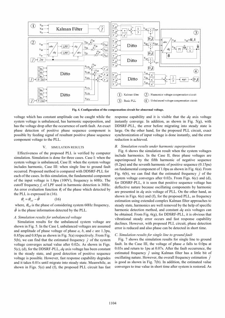
voltage which has constant amplitude can be caught while the system voltage is unbalanced, has harmonic superposition, and has the voltage drop after the occurrence of earth fault. An exact phase detection of positive phase sequence component is possible by feeding signal of resultant positive phase sequence component voltage to the PLL.
V. SIMULATION RESULTS Effectiveness of the proposed PLL is verified by computer
simulation. Simulation is done for three cases. Case I: when the system voltage is unbalanced, Case II: when the system voltage includes harmonic, Case III: when single line to ground fault occurred. Proposed method is compared with DDSRF-PLL for each of the cases. In this simulation, the fundamental component of the input voltage is 1.0pu (100V), frequency is 60Hz. The cutoff frequency fc of LPF used in harmonic detection is 30Hz. An error evaluation function θe of the phase which detected by the PLL is expressed in (16).
)16(θ̂θθ −= refe where, θref is the phase of considering system 60Hz frequency, θ̂ is the phase information detected by the PLL.
A. Simulation results for unbalanced voltage Simulation results for the unbalanced system voltage are
shown in Fig. 5. In the Case I, unbalanced voltages are assumed and amplitude of phase voltage of phase a, b, and c are 1.3pu, 0.85pu and 0.85pu as shown in Fig. 5(a) respectively. From Fig. 5(b), we can find that the estimated frequency f̂ of the system voltage converges actual value after 0.02s. As shown in Figs. 5(c), (d), for the DDSRF-PLL, dq axis voltage has been constant in the steady state, and good detection of positive sequence voltage is possible. However, fast response capability degrades and it takes 0.01s until migrate into steady state. Meanwhile, as shown in Figs. 5(e) and (f), the proposed PLL circuit has fast
response capability and it is visible that the dq axis voltage instantly converge. In addition, as shown in Fig. 5(g), with DDSRF-PLL, the error before migrating into steady state is large. On the other hand, for the proposed PLL circuit, exact synchronization of input voltage is done instantly, and the error reduction is achieved.
B. Simulation results under harmonic superposition Fig. 6 shows the simulation result when the system voltages
include harmonics. In the Case II, three phase voltages are superimposed by the fifth harmonic of negative sequence (0.2pu) and the seventh harmonic of positive sequence (0.15pu) on fundamental component of 1.0pu as shown in Fig. 6(a). From Fig. 6(b), we can find that the estimated frequency f̂ of the system voltage converges after 0.02s. From Figs. 6(c) and (d), for DDSRF-PLL, it is seen that positive sequence voltage has deflective nature because oscillating components by harmonic are presented in dq axis voltage of PLL. On the other hand, as shown in Figs. 6(e) and (f), for the proposed PLL, as frequency estimation using extended complex Kalman filter approaches to steady state, harmonics are well removed by the help of specific harmonic detection method, and constant dq axis voltages can be obtained. From Fig. 6(g), for DDSRF-PLL, it is obvious that vibrational steady error occurs and fast response capability declines. However, with proposed PLL circuit, phase detection error is reduced and also phase can be detected in short time.
C. Simulation results for single line to ground fault Fig. 7 shows the simulation results for single line to ground
fault. In the Case III, the voltage of phase a falls to 0.0pu at 0.03s and return to 1pu at 0.07s. After the fault occurrence, the estimated frequency f̂ using Kalman filter has a little bit of oscillating nature. However, the overall frequency estimation f̂ is good as shown in Fig. 7(b). In addition, the estimated value converges to true value in short time after system is restored. As
Fig. 4. Configuration of the compensation circuit for abnormal voltage.
1104

(a) Grid voltage.
(b) Estimated frequency.
(c) dq-axis voltage (DDSRF-PLL).
(d) Positive sequence voltage (DDSRF-PLL).
(e) dq-axis voltage (proposed method).
(f) Positive sequence voltage (proposed method).
(g) Detected phase angle error.
Fig. 5. Response of PLL for unbalanced voltage.
(a) Grid voltage.
(b) Estimated frequency.
(c) dq-axis voltage (DDSRF-PLL).
(d) Positive sequence voltage (DDSRF-PLL).
(e) dq-axis voltage (proposed method).
(f) Positive sequence voltage (proposed method).
(g) Detected phase angle error.
Fig. 6. Response of PLL for harmonic.
1105

(a) Grid voltage.
(b) Estimated frequency.
(c) dq-axis voltage (DDSRF-PLL).
(d) Positive sequence voltage (DDSRF-PLL).
(e) dq-axis voltage (proposed method).
(f) Positive sequence voltage (proposed method).
(g) Detected phase angle error.
Fig. 7. Response of PLL for single line to ground fault.
shown Figs. 7(c), (d), for DDSRF-PLL, phase following capability fluctuates largely because fluctuations appear in dq axis voltages of the PLL and in amplitude of positive sequence voltage as voltage dropped due to fault. On the other hand, from Figs. 7(e), (f), for the proposed PLL circuit, constant voltage is obtained when the voltage dropped after fault occurrence. Thus the detection of the positive sequence voltage is possible. Fig. 7(g) shows that error of phase detection is reduced and excellent phase detection is achieved even during fault by using proposed PLL circuit.
VI. CONCLUSION This paper presents the PLL circuit which has the excellent
phase detection for an unbalanced voltage and harmonics. In the proposed technique, the compensation circuit for harmonic and unbalanced voltage is composed with basic PLL circuit. The harmonic compensation circuit eliminates harmonic component of each order of the input voltage using specific harmonic detection method. The frequency information of power system which is used in specific harmonic detection method, estimated by extended complex Kalman filter. To obtain balanced three phase voltage signals with constant amplitude, the unbalanced voltage compensation circuit computed the positive sequence components and normalized the input phase voltage. In order to validate effectiveness of the proposed PLL, it is compared with DDSRF-PLL. From simulation results, the proposed PLL achieved excellent phase detection under the conditions of unbalanced voltage, harmonics, and single line to ground fault.
REFERENCES [1] B. Han and B. Bae, “Novel Phase-Locked Loop Using Adaptive Linear
Combiner,” IEEE. Trans. on Power Delivery, vol. 21, no. 1, 2006. [2] Victor M. Moreno, M Liserre, A. Piberto, and A Dell’Aquila, “A
Comparative Analysis of Real-Time Algorithms for Power Signal Decomposition in Multiple Synchronous Reference Frames,” IEEE Trans. on Power Electronics, vol. 22, no. 4, 2007.
[3] F. Blaabjerg, Remus. Teodorescu, M. Liserre, and A. V. Timbus, “Overview of Control and Grid Synchronization for Distributed Power Generation Systems,” IEEE Trans. on Industrial Electronics, vol. 53, no. 5, pp. 1398-1409, 2006.
[4] Pedro Rodriguez, Josep Pou, Joan Bergas, J. Ignacio, Rolando P. Burgos, and Dushan Boroyevich, “Decoupled Double Synchronous Reference Frame PLL for Power Converters Control,” IEEE Trans. on Power Electronics, vol. 22, no. 2, pp. 584-592, 2007.
[5] H. Yamashita, P. Jintakosonwit, H. Fujita, H. Akagi, and J. Shinohara, “Discussions and Comparisons between Comprehensive Harmonic Detection and Specific Harmonic Detection in a Shunt Active Filter for Installation on a Power Distribution System,” T. IEE Japan, vol. 124-D, no. 6, pp.622-629, 2004. (in Japanese)
[6] T. Takeshita, and Y. Ueoka, “Design of Harmonics Extraction Filter for Three-Phase System,” T. IEE Japan, vol. 126-D, no. 4, pp. 527-528, 2006. (in Japanese)
[7] P. K. Dash, A. K. Pradhan, and G. Panda, “Frequency Estimation of Distorted Power System Signals Using Extended Complex Kalman Filter ,” IEEE Trans. on Power Delivery, vol. 14, no. 3, 1999.
[8] K. Nishiyama and O. Satou, “A Consideration on Extended Complex Kalman Filter for Estimating a Sinusoidal Signal and Its Parameters in White Noise,” IEICE Trans., vol. J77-A, no. 7, pp.1023-1027, 1994. (in Japanese)
[9] M. Akamatsu, M. Tsukada, and D. Itou, “A Novel PLL and Frequency Detecting Method Suited for the Abnormal Voltages under Fault Conditions in the Power System,” T. IEE Japan, vol. 118-B, no.9, pp. 955-961, 1998. (in Japanese)
1106