Flexible unbalanced control with peak current limitation ... · Flexible unbalanced control with...
12
Flexible unbalanced control with peak current limitation for virtual synchronous generator under voltage sags Tianwen ZHENG 1 , Laijun CHEN 1,2 , Yan GUO 1 , Shengwei MEI 1,2 Abstract Virtual synchronous generator (VSG) is grid- friendly for integrating distributed generations (DGs) since it can emulate the operation mechanism of traditional synchronous generator (SG). However, the traditional VSG control strategy, which is mainly suitable for balanced voltage conditions, may lead to power oscillations, current unbalance and even overcurrent under unbalanced voltage sags. To overcome this difficulty, a flexible unbalanced control with peak current limitation for VSG under unbalanced operating conditions is proposed. Based on the basic VSG control algorithm, the control strategy integrates two novel control modules, which are current reference generator (CRG) and power reference generator (PRG). The proposed control strategy can flexibly meet different operation demands, which includes current balancing, constant active or reactive power. And the injected currents are kept within safety values for a better utilization of the VSG power capacity. Furthermore, the experimental plat- form is built. Experimental results demonstrate the valid- ness and effectiveness of the proposed control strategy. Keywords Virtual synchronous generator, Unbalanced control, Current reference generator, Power reference generator, Voltage sags 1 Introduction With the technology of renewable generation becoming mature, the penetration of distributed generations (DGs) connected to the distribution network is growing rapidly. Generally, renewable DGs connect to the grid through power electronic converters, which reduces the total inertia and deteriorate system damping property. With the pene- tration level of DG increasing, such converter-dominant power distribution infrastructure will suffer from the lacking of inertial and damping. Meanwhile, the power system is prone to become unstable if the penetration of converter type DGs reaches a certain threshold [1, 2]. On the other hand, the high controllability and fast response of power electronic devices provide unique opportunity to provide virtual inertia and damping through the power converters. The basic idea is known as virtual synchronous generator (VSG) which can behave as syn- chronous generator (SG) with inertia and damping, so as to enhance the system stability. VSG is playing an increas- ingly important role in power systems due to its control- lability and flexibility, especially in microgrids and active distribution power networks [3, 4]. The original concept of VSG is proposed in the Europe VSYNC project [5, 6], after that, many other kinds of VSG CrossCheck date: 17 February 2017 Received: 18 January 2016 / Accepted: 17 February 2017 / Published online: 27 May 2017 Ó The Author(s) 2017. This article is an open access publication & Laijun CHEN [email protected] Tianwen ZHENG [email protected] Yan GUO [email protected] Shengwei MEI [email protected] 1 State Key Laboratory of Control and Simulation of Power Systems and Generation Equipments, Department of Electrical Engineering, Tsinghua University, Beijing 100084, China 2 Qinghai Key Lab of Efficient Utilization of Clean Energy, New Energy Photovoltaic Industry Research Center, Qinghai University, Xining 810016, China 123 J. Mod. Power Syst. Clean Energy (2018) 6(1):61–72 https://doi.org/10.1007/s40565-017-0295-y
Transcript of Flexible unbalanced control with peak current limitation ... · Flexible unbalanced control with...
Flexible unbalanced control with peak current limitationfor virtual synchronous generator under voltage sags
Tianwen ZHENG1, Laijun CHEN1,2, Yan GUO1, Shengwei MEI1,2
Abstract Virtual synchronous generator (VSG) is grid-
friendly for integrating distributed generations (DGs) since
it can emulate the operation mechanism of traditional
synchronous generator (SG). However, the traditional VSG
control strategy, which is mainly suitable for balanced
voltage conditions, may lead to power oscillations, current
unbalance and even overcurrent under unbalanced voltage
sags. To overcome this difficulty, a flexible unbalanced
control with peak current limitation for VSG under
unbalanced operating conditions is proposed. Based on the
basic VSG control algorithm, the control strategy integrates
two novel control modules, which are current reference
generator (CRG) and power reference generator (PRG).
The proposed control strategy can flexibly meet different
operation demands, which includes current balancing,
constant active or reactive power. And the injected currents
are kept within safety values for a better utilization of the
VSG power capacity. Furthermore, the experimental plat-
form is built. Experimental results demonstrate the valid-
ness and effectiveness of the proposed control strategy.
Keywords Virtual synchronous generator, Unbalanced
control, Current reference generator, Power reference
generator, Voltage sags
1 Introduction
With the technology of renewable generation becoming
mature, the penetration of distributed generations (DGs)
connected to the distribution network is growing rapidly.
Generally, renewable DGs connect to the grid through
power electronic converters, which reduces the total inertia
and deteriorate system damping property. With the pene-
tration level of DG increasing, such converter-dominant
power distribution infrastructure will suffer from the
lacking of inertial and damping. Meanwhile, the power
system is prone to become unstable if the penetration of
converter type DGs reaches a certain threshold [1, 2].
On the other hand, the high controllability and fast
response of power electronic devices provide unique
opportunity to provide virtual inertia and damping through
the power converters. The basic idea is known as virtual
synchronous generator (VSG) which can behave as syn-
chronous generator (SG) with inertia and damping, so as to
enhance the system stability. VSG is playing an increas-
ingly important role in power systems due to its control-
lability and flexibility, especially in microgrids and active
distribution power networks [3, 4].
The original concept of VSG is proposed in the Europe
VSYNC project [5, 6], after that, many other kinds of VSG
CrossCheck date: 17 February 2017
Received: 18 January 2016 / Accepted: 17 February 2017 / Published
online: 27 May 2017
� The Author(s) 2017. This article is an open access publication
& Laijun CHEN
Tianwen ZHENG
Yan GUO
Shengwei MEI
1 State Key Laboratory of Control and Simulation of Power
Systems and Generation Equipments, Department of
Electrical Engineering, Tsinghua University, Beijing 100084,
China
2 Qinghai Key Lab of Efficient Utilization of Clean Energy,
New Energy Photovoltaic Industry Research Center, Qinghai
University, Xining 810016, China
123
J. Mod. Power Syst. Clean Energy (2018) 6(1):61–72
https://doi.org/10.1007/s40565-017-0295-y
are presented to improve the performance, including the
synchronous-VSC and the synchronverter [7–11]. In view
of the operational advantages, the voltage-controlled VSG
is attracting more and more attentions, including VSG
modelling [5, 8], control strategy design [10–13] and sta-
bility analysis [14, 15].
The VSG control strategy has been one of the major
research directions in recent years. In [10], a VSG with the
functionality of constant PQ control and V/f control is
proposed, which can meet various operation requirements.
The constant power control strategy with droop mechanism
is designed to allocate the active and reactive power
between multiple VSGs [11]. A comprehensive control
framework with frequency, angle and virtual torque control
loops is developed to further imitate the behavior of a SG
[12].
It is worth mentioning that the aforementioned methods
are developed under balanced and normal grid voltage
conditions. However, the distribution grid voltage is
influenced by many factors, such as overloads, startup of
motors and asymmetric faults, which all may result in
asymmetric or symmetric voltage sags [16]. Moreover,
current unbalance, power oscillation or even overcurrent
may be emerged when traditional VSG control strategies
are adopted under voltage sags, which may cause VSG
protection or outage.
In the field of traditional inverter control, voltage sags
have been shown to be one of the greatest challenges for
inverters control in order to keep them operating normally.
In [17], a current reference calculation method is intro-
duced to provide voltage support. Reference [18] aims at
reducing active power oscillation to exploit the maximum
capability of distributed generation. In [19, 20], the selec-
tion of a proper current reference is proposed to override
grid faults and meet different power quality requirements.
Other interesting methods have also been reported to
address this issue, which manage to either balance three
phase currents, or reduce the active or reactive power
oscillations under unbalanced grid voltage [21, 22].
Nevertheless, the proposed inverter control methods
under voltage sags are mainly for the current-controlled
inverter that can be equivalent to a current source. The
VSG, however, is emulated as a voltage-source, which is
inherently distinct from the traditional inverter. The tradi-
tional inverter unbalanced control strategies cannot be
mechanically applied to the VSG control under unbalanced
voltage. Therefore, another significant concern related to
VSG control is the ability to operate well under the con-
ditions of voltage sags, which is important but about which
few researches have been conducted.
Some inspirations are drawn from the traditional
inverter control strategies under voltage sags. To provide
balanced current or constant active power output under
unbalanced grid voltage, the improved VSG control strat-
egy is proposed in [23, 24], respectively. They are helpful
and enlightening for designing VSG unbalanced control
though they are simple without considering additional
important targets.
Motivated by the aforementioned issues, a flexible
unbalanced control strategy for VSG is comprehensively
studied in this paper. The proposed flexible control strategy
is cascaded with novel current reference generator (CRG)
and power reference generator (PRG) together with the
basic VSG controller and a double sequence frame current
regulator, which can flexibly meet different operation
requirements under varying voltage conditions. The control
strategy is advantageous in twofold: � current reference
generator is an essential module to achieve different
unbalanced control objectives, which manages to either
balance three phase currents, or provide constant active or
reactive power; ` power reference generator with peak
current limitation is another important module, which can
make full utilization of the maximum current to provide
power supports and avoid overcurrent tripping or device
damage.
The rest of the paper is organized as follows. The basic
problem formulation including VSG control topology and
essential properties are introduced in Section 2. The cas-
caded control framework and design process are presented
in Section 3. Experimental results in Section 4 corroborate
the claimed features of the proposed controller. Conclu-
sions are drawn in Section 5.
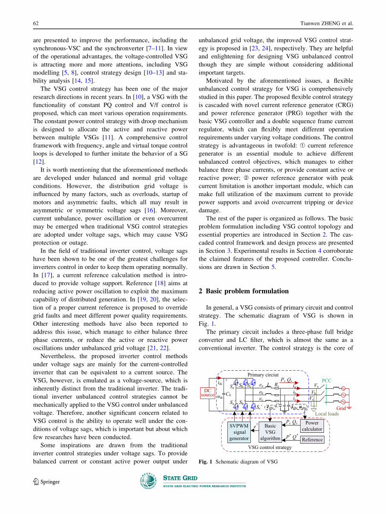
2 Basic problem formulation
In general, a VSG consists of primary circuit and control
strategy. The schematic diagram of VSG is shown in
Fig. 1.
The primary circuit includes a three-phase full bridge
converter and LC filter, which is almost the same as a
conventional inverter. The control strategy is the core of
DCsource
GridLocal loads
SVPWM signal
generator
Basic VSG
algorithm
Power calculator
ReferenceVSG control strategy
Primary circiutPCC
Sa Sb Sc
C0udc
idc
Sa SbSc
ea
eb
ec
L Rs
Ceabc
Pe Qeia
ibic
Va
VbVc
iabc uabc
Pe Qe
P* Q*
e*
Fig. 1 Schematic diagram of VSG
62 Tianwen ZHENG et al.
123

VSG that can make it mimic the operation mechanism as a
SG. The basic VSG algorithm is described by [23, 24]:
JdDxdt
¼ P�
x� Pe
x� DDx
dhdt
¼ x
1
Kq
ZðQ� � QeÞ þ Dqðv�rms � vrmsÞ ¼ E
8>>>>>><>>>>>>:
ð1Þ
where P* and Q* are the reference of active power and
reactive power; Pe and Qe are the electromagnetic active
power and reactive power, which can be calculated through
v = [va vb vc]T and i = [ia ib ic]
T; e = [ea eb ec]T is the output
voltage of the IGBTs; E is the magnitude; Dp, Dq, J are the
damping coefficient, voltage droop coefficient and system
inertia, respectively; Kq is the integral coefficient; x and hare the virtual angle speed and virtual angular. The voltage
reference e* can be composed as E\hWhen VSG is operated under unbalanced voltage sags,
the output current and power are strongly affected by the
PCC voltage. Similar to common grid-connected inverters,
the negative sequence components of VSG also appear
when the voltage is asymmetrical, which may distort the
current and power waveforms. The VSG output power can
be obtained as follows [23]:
p ¼ p0 þ pc2 cosð2xtÞ þ ps2 sinð2xtÞq ¼ q0 þ qc2 cosð2xtÞ þ qs2 sinð2xtÞ
(ð2Þ
where p0 and q0 are the average value of active and reactive
power; pc2, ps2, qc2, qs2 are the double frequency oscilla-
tions of the power.
From (2), it can be seen that the double frequency
oscillations are produced under unbalanced voltage sags,
where the negative sequence voltage and current are not
equal to zero. The active and reactive power can be cal-
culated by:
p0
q0
ps2
pc2
qc2
qs2
26666666664
37777777775¼ 3
2
vþdvþq
vþq
�vþd
v�dv�q
v�q
�v�dv�q
v�d
�v�dv�q
�vþq
vþd
vþdvþq
v�q �v�d vþq �vþd�v�d �v�q vþd vþq
2666666664
3777777775
iþdiþq
i�di�q
266664
377775 ð3Þ
From (3), it can be concluded that there are only four
control freedoms (id?, iq
?, id-, iq
-) for controlling six
variables (p0, q0, ps2, pc2, qs2, qc2). As a result, it is
difficult to achieve multiple objectives at the same time.
For instance, it is very difficult to provide constant active
power (ps2 and pc2 are eliminated) and obtain balanced
current simultaneously.
3 Proposed flexible control strategy
3.1 Cascaded control framework
To achieve different control objectives as well as remain
the properties of VSG, the proposed flexible control strat-
egy is designed as a cascaded control framework, which
mainly includes four modules: basic VSG algorithm, a
novel CRG, an innovative PRG, and a typical current
regulator. The cascaded control framework is designed as
shown in Fig. 2.
From Fig. 2, it can be seen that the CRG and PRG are
the kernel and novel modules of the proposed control
framework. Thereinto, the CRG is used to generate current
reference, which can achieve the targets of current bal-
ancing, constant active or reactive power output under
unbalanced voltage. The PRG is mainly in charge of pro-
ducing power reference to make full use of the maximum
allowance current to provide power supports and avoid
overcurrent for VSG under unbalanced voltage sags. Fur-
thermore, the basic VSG algorithm and the typical current
regulator including the positive and negative sequence
control loops have been described in detail in [23, 24].
Thus the CRG and PRG will be elaborated hereinafter.
3.2 Current reference generator
As previously analysis, when VSG operates under
unbalanced voltage sags, the primary objective is to either
balance the grid injected currents, or deliver constant active
or reactive power. CRG is a key component of the pro-
posed control strategy since it can obtain the current ref-
erence for different objectives. That is to say, the control
strategy can flexibly achieve these objectives by injecting
different amounts of positive and negative sequence cur-
rent reference produced by the current reference generator.
3.2.1 Balanced current mode
To some extent, unbalanced or distorted current cannot
be accepted from the point view of power utilities. To
obtain symmetrical grid-connected currents, only positive
sequence components are required, where the negative
sequence current reference is forced at zero. However, the
dq/abc
Power reference generator
(PRG)
Basic VSG
algorithm
Current reference generator
(CRG)
Typical current
regulator i
v P*
Q*e* i*
e *d
e *q
e *
Fig. 2 Cascaded control framework
Flexible unbalanced control with peak current limitation for virtual synchronous generator… 63
123

positive sequence current cannot be calculated by (3)
directly due to the influence of traditional VSG control.
Therefore, the voltage reference produced by the tradi-
tional VSG controller and the circuit equation should be
utilized to calculate the positive sequence current refer-
ence, which is inherently difference from traditional
inverter control. From the VSG topology in Fig. 1, it can be
deduced that:
ed
eq
" #¼
vþdvþq
" #þ Lpþ R �xL
xL Lpþ R
� �iþdiþq
" #ð4Þ
where p = d/dt, which represents the differential operator;
L is the total inductance from the VSG to the grid. And the
other variables have been explained in Fig. 1. Owing to
VSG controller, the stable value can approach to the
predefined reference value. Therefore, (4) can be
transformed into frequency domain as:
Iþd ðsÞ
Iþq ðsÞ
" #¼
Lsþ R �xL
xL Lsþ R
� ��1 EdðsÞ
EqðsÞ
" #�
Vþd ðsÞ
Vþq ðsÞ
" # !
¼ 1
ðLsþ RÞ2 þ ðxLÞ2ðLsþ RÞDVþ
d ðsÞ þ xLDVþq ðsÞ
ðLsþ RÞDVþq ðsÞ � xLDVþ
d ðsÞ
" #
ð5Þ
where DVþd sð Þ ¼ Ed sð Þ � Vþ
d sð Þ; DVþq sð Þ ¼ Eq sð Þ� Vþ
q sð Þ;s is the complex frequency.
Based on the Laplace final-value theorem, the positive
sequence current reference can be deduced from (5), which
is shown as follows:
iþ�d
iþ�q
" #¼ 1
R2 þ ðxLÞ2RDvþd þ xLDvþqRDvþq � xLDvþd
� �ð6Þ
where Dvþd ¼ ed � vþd ; Dvþq ¼ eq � vþq .
It is worth noting that the final output power, especially
the average value of power, does not rely on the exact
circuit parameters (R or L), because the output power of the
integral control loop in VSG control can be adjusted
automatically. The proof process is shown in Appendix
A.
Furthermore, the output power oscillations are depressed
because the negative sequence current is eliminated.
Therefore, if high quality of grid-connected current is
desired, the balanced current mode (BCM) will be the best
choice.
3.2.2 Constant active power mode
As mentioned before, one way to provide constant
active power is to make pc2 and ps2 equal to zero. That is:
v�q �v�dv�d v�q
� �iþdiþq
� �þ
�vþq vþdvþd vþq
� �i�di�q
� �¼ 0 ð7Þ
From (7), it can be seen that the reference of positive
and negative sequence current should be included in the
control system in order to eliminate active power
fluctuation. The negative sequence current reference can
be easily obtained from (7).
i��d
i��q
" #¼ �1
ðvþd Þ2 þ ðvþq Þ
2
�vþq v�q þ vþd v
�d vþq v
�d þ vþd v
�q
vþd v�q þ vþq v
�d �vþd v
�d þ vþq v
�q
" #
�iþ�d
iþ�q
" #
ð8Þ
Equation (8) indicates that the negative sequence current
reference can be conveniently derived with positive
sequence current reference. Under this control condition,
the active power fluctuation is deeply reduced, but the
quadrature magnitudes of oscillating reactive power is also
large due to the negative sequence currents are not
removed. Thereby, the constant active power mode
(CAPM) is mainly suitable in the situation that constant
active power flow is desired.
3.2.3 Constant reactive power mode
For some large capacity power generation equipment,
the capability to provide stable reactive power supports is
strongly required. Similar to the active power oscillation
control, taking qc2 = qs2 = 0 is the basic idea to ensure
constant reactive power output. That is:
v�q �v�dv�d v�q
� �iþdiþq
� �� �vþq vþd
vþd vþq
� �i�di�q
� �¼ 0 ð9Þ
Dealing with (9), the injected negative sequence current
reference used to reduce the reactive power oscillation is
generated by:
i��d
i��q
" #¼ 1
ðvþd Þ2 þ ðvþq Þ
2
�vþq v�q þ vþd v
�d vþq v
�d þ vþd v
�q
vþd v�q þ vþq v
�d �vþd v
�d þ vþq v
�q
" #
�iþ�d
iþ�q
" #
ð10Þ
From (8) and (10), it is interesting to notice that those
two results are opposite, which provide much more
convenience to unify the algorithm. Therefore, (6), (8)
and (10) can be combined as:
64 Tianwen ZHENG et al.
123

iþ�d
iþ�q
i��d
i��q
2666664
3777775¼ 1
ðvþd Þ2 þ ðvþq Þ
2
�
ðvþd Þ2 þ ðvþq Þ
2
0
Nð�vþq v�q þ vþd v
�d Þ
0
ðvþd Þ2 þ ðvþq Þ
2
Nðvþq v�d þ vþd v�q Þ
Nðvþd v�q þ vþq v�d Þ Nð�vþd v
�d þ vþq v
�q Þ
2666664
3777775
iþ�d
iþ�q
" #
ð11Þ
where N is the unifying factor, which is an integer in the
range of [-1, 1]. In fact, N can be used to select the
required control targets. When N = 0, (11) can be combined
with (6), which the injected grid current is balanced.
Similarly, when N = ±1, (11) converts to (10) and (8) to
remove active power and reactive power oscillation.
Therefore, it is flexible to customize the control objectives
for different demands.
3.3 Power reference generator
If the active power or reactive power reference is con-
stant, current may exceed the maximum allowable value
during voltage sags. To avoid the risk of overcurrent, the
active and reactive power reference should be obtained
through a power calculator instead of a predefined value.
For different control objects, there are corresponding
power references.
3.3.1 Peak current calculation
As a basic part of the PRG, the peak current calculation
is applied to quantitatively analyse the relationship
between the power and allowable output current under
voltage sags. In order to elaborate the calculation process,
take the ‘CAPM’ as an example. When the control objec-
tive is CAPM, use (3) and make pc2 and ps2 equal to zero
again. The output current in dq axis can be determined as:
iþdiþq
i�di�q
266664
377775 ¼ 2p0
3 D1 � D2ð Þ
vþdvþq�v�d�v�q
2664
3775þ 2q0
3 D1 þ D2ð Þ
vþq�vþdv�q�v�d
2664
3775
ð12Þ
where D1 ¼ vþd� �2þ vþq
� �2, D2 ¼ v�d
� �2þ v�q
� �2.
Then, applying the inverse Park transformation to (12),
the instantaneous values of VSG output currents can be
expressed as:
where K1 ¼ 2p03ðD1�D2Þ; K2 ¼ 2q0
3ðD1þD2Þ; h? = xt ? u?,
h- = -xt ? u-, which are the positive and negative
sequence reference angles; u? and u- are arbitrary angle.
Furthermore, the instantaneous values of the phase currents
can be obtained from (13) and (14). Take phase A for
instance, the peak value of output current can be expressed
as:
ia ¼ K1vþd þ K2v
þq
� �cos hþ þ K2v
þd � K1v
þq
� �sin hþ
þ K2v�q � K1v
�d
� �cos h� þ K1v
�q þ K2v
�d
� �sin h�
ð15Þ
Let A1 ¼ K1vþd þ K2v
þq , A2 ¼ K2v
þd � K1v
þq , A3 =
K2vq- - K1vd
-, A4 = K1vq- ? K2vd
-. Then the current peak
value of phase A can be extracted from (15) by using
trigonometric formula, that is:
iam
¼ffiffiffiffiffiffiffiffiffiffiffiffiffiffiffiffiffiffiffiffiffiffiffiffiffiffiffiffiffiffiffiffiffiffiffiffiffiffiffiffiffiffiffiffiffiffiffiffiffiffiffiffiffiffiffiffiffiffiffiffiffiffiffiffiffiffiffiffiffiffiffiffiffiffiffiffiffiffiffiffiffiffiffiffiffiffiffiffiffiffiffiffiffiffiffiffiffiffiffiffiffiffiffiffiffiffiffiffiffiffiffiffiffiffiA21 þ A2
2 þ A23 þ A2
4 þ 2
ffiffiffiffiffiffiffiffiffiffiffiffiffiffiffiffiA21 þ A2
2
q ffiffiffiffiffiffiffiffiffiffiffiffiffiffiffiffiA23 þ A2
4
qcosðDu� u0Þ
r
ð16Þ
iþaiþbiþc
264
375 ¼
K1 cos hþ þ K2 sin h
þ K2 cos hþ � K1 sin h
þ
K1 cos hþ � 2
3p
þ K2 sin hþ � 2
3p
K2 cos hþ � 2
3p
� K1 sin hþ � 2
3p
K1 cos hþ þ 2
3p
þ K2 sin hþ þ 2
3p
K2 cos hþ þ 2
3p
� K1 sin hþ þ 2
3p
266664
377775
vþdvþq
" #ð13Þ
i�ai�bi�c
264
375 ¼
K2 sin h� � K1 cos h
� K1 sin h� þ K2 cos h
�
K2 sin h� � 2
3p
� K1 cos h� � 2
3p
K1 sin h� � 2
3p
þ K2 cos h� � 2
3p
K2 sin h� þ 2
3p
� K1 cos h� þ 2
3p
K1 sin h� þ 2
3p
þ K2 cos h� þ 2
3p
266664
377775
v�dv�q
" #ð14Þ
Flexible unbalanced control with peak current limitation for virtual synchronous generator… 65
123
where Du = h? ? h- = u? ? u-, u0 ¼ arctan A2
A1þ
arctan A4
A3.
In the same way, the current peak value of phase B and
phase C can be express as
From (16)–(18), it can be seen clearly that the possible
maximum current will appear in phase A, B and C when
Du = u0, Du ¼ u0 þ 2
3p, Du ¼ u0 � 2
3p, respectively. The
maximum current value can be expressed as:
Im ¼ffiffiffiffiffiffiffiffiffiffiffiffiffiffiffiffiA21 þ A2
2
qþ
ffiffiffiffiffiffiffiffiffiffiffiffiffiffiffiffiA23 þ A2
4
qð19Þ
Then substituting A1, A2, A3 and A4 to (19), the
maximum current of VSG in CAPM can also be
expressed as:
Im ¼
ffiffiffiffiffiffiffiffiffiffiffiffiffiffiffiffiffiffiffiffiffiffiffiffiffiffiffiffiffiffiffiffiffiffiffiffiffiffiffiffiffiffiffiffiffiffiffiffiffiffiffiffiffiffiffiffiffiffiffiffiffiffiffiffiffiffiffi2p0
3 D1 � D2ð Þ
2
þ 2q0
3 D1 þ D2ð Þ
2s ffiffiffiffiffiffi
D1
pþ
ffiffiffiffiffiffiD2
p� �
ð20Þ
From (20), it can be seen that Im is strongly related with
p0 and q0. As a consequence, p0 and q0 deeply depend upon
the power reference. Therefore, one effective way to
reasonably reduce Im is changing the value of power
reference automatically.
3.3.2 Power reference calculation
Take CAPM for instance again. If the permissible peak
current of VSG is Imax, which means that Im should be less
than Imax. Generally, Imax is set below the overcurrent
protection threshold to avoid the risk of overcurrent shut-
down of VSG. Then, combining with (20), the active and
reactive power reference must be limited by means of the
following condition to avoid VSG overcurrent.ffiffiffiffiffiffiffiffiffiffiffiffiffiffiffiffiffiffiffiffiffiffiffiffiffiffiffiffiffiffiffiffiffiffiffiffiffiffiffiffiffiffiffiffiffiffiffiffiffiffiffiffiffiffiffiP�
D1 � D2
2
þ Q�
D1 þ D2
2s
� 1:5ImaxffiffiffiffiffiffiD1
pþ
ffiffiffiffiffiffiD2
p ð21Þ
When asymmetric voltage sags happen, the VSG output
current can be limited to the maximum allowed value if
(21) is satisfied. However, (21) only gives the condition for
current limitation, which cannot certainly generate the
active and reactive power reference due to two unknown
parameters (P* and Q*) in only one function. It is worth
noting that during voltage sags, one of the important
functionality of VSG is to provide power support for the
power grid. And in general, the reactive power demand is a
little larger than the active power. Thus, it is reasonable to
design the reactive power reference to be no less than the
active power reference during voltage sags. That is:
P� ¼ kQ� 0� k� 1 ð22Þ
Then, the power reference of CAPM can be determined
by solving (21) and (22).
Q�1 ¼
1:5 D1 þ D2ð ÞffiffiffiffiffiffiD1
p�
ffiffiffiffiffiffiD2
p� �Imaxffiffiffiffiffiffiffiffiffiffiffiffiffiffiffiffiffiffiffiffiffiffiffiffiffiffiffiffiffiffiffiffiffiffiffiffiffiffiffiffiffiffiffiffiffiffiffiffiffiffiffiffiffi
k2 D1 þ D2ð Þ2þ D1 � D2ð Þ2q
P�1 ¼ kQ�
1
8>><>>:
ð23Þ
From (23), it can be seen that there are two potential
problems. One is that little current margin has been left,
which may lead to overcurrent due to a small disturbance
or inaccuracy. The other is that the calculation turns out too
complicated for practical application. Therefore, (23)
should be simplified in a reasonable way.
Firstly, it can be proved that when 0BkB1,1:5ðD1þD2Þffiffiffiffiffiffiffiffiffiffiffiffiffiffiffiffiffiffiffiffiffiffiffiffiffiffiffiffiffiffiffiffiffiffiffi
k2ðD1þD2Þ2þðD1�D2Þ2p [ 1. Consequently, (23) can be facil-
itated into a more effective form:
Q�¼ Vþ � V�ð ÞImax
P� ¼ kQ�
(ð24Þ
where V? and V- are the amplitude of positive and nega-
tive sequence grid voltage.
They can be obtained by Vþ ¼ffiffiffiffiffiffiffiffiffiffiffiffiffiffiffiffiffiffiffiffiffiffiffiffiffiffiffiffiðvþd Þ
2 þ ðvþq Þ2
qand
V� ¼ffiffiffiffiffiffiffiffiffiffiffiffiffiffiffiffiffiffiffiffiffiffiffiffiffiffiffiffiðv�d Þ
2 þ ðv�q Þ2
q.
3.3.3 Unified form of PRG
As mentioned above, the process of peak current cal-
culation and power reference calculation in CAPM are
illustrated in detail. The PRG of constant reactive power
ibm ¼
ffiffiffiffiffiffiffiffiffiffiffiffiffiffiffiffiffiffiffiffiffiffiffiffiffiffiffiffiffiffiffiffiffiffiffiffiffiffiffiffiffiffiffiffiffiffiffiffiffiffiffiffiffiffiffiffiffiffiffiffiffiffiffiffiffiffiffiffiffiffiffiffiffiffiffiffiffiffiffiffiffiffiffiffiffiffiffiffiffiffiffiffiffiffiffiffiffiffiffiffiffiffiffiffiffiffiffiffiffiffiffiffiffiffiffiffiffiffiffiffiffiffiffiffiffiffiffiffiffiA21 þ A2
2 þ A23 þ A2
4 þ 2
ffiffiffiffiffiffiffiffiffiffiffiffiffiffiffiffiA21 þ A2
2
q ffiffiffiffiffiffiffiffiffiffiffiffiffiffiffiffiA23 þ A2
4
qcos Du� u0 � 2
3p
sð17Þ
icm ¼
ffiffiffiffiffiffiffiffiffiffiffiffiffiffiffiffiffiffiffiffiffiffiffiffiffiffiffiffiffiffiffiffiffiffiffiffiffiffiffiffiffiffiffiffiffiffiffiffiffiffiffiffiffiffiffiffiffiffiffiffiffiffiffiffiffiffiffiffiffiffiffiffiffiffiffiffiffiffiffiffiffiffiffiffiffiffiffiffiffiffiffiffiffiffiffiffiffiffiffiffiffiffiffiffiffiffiffiffiffiffiffiffiffiffiffiffiffiffiffiffiffiffiffiffiffiffiffiffiffiA21 þ A2
2 þ A23 þ A2
4 þ 2
ffiffiffiffiffiffiffiffiffiffiffiffiffiffiffiffiA21 þ A2
2
q ffiffiffiffiffiffiffiffiffiffiffiffiffiffiffiffiA23 þ A2
4
qcos Du� u0 þ 2
3p
sð18Þ
66 Tianwen ZHENG et al.
123
mode (CRPM) and BCM can be obtained in the same way
as previously analysis. To facilitate the description, the
PRG of CRPM and BCM are simply described as
follows.
1) PRG of CRPM
PRG of CRPMWhen the control objective is to provide
constant reactive power, the output currents in dq axis can
be determined as:
iþdiþq
i�di�q
266664
377775 ¼ 2p0
3 D1 þ D2ð Þ
vþdvþq
�v�d�v�q
266664
377775þ 2q0
3 D1 � D2ð Þ
vþq
�vþdv�q
�v�d
266664
377775
ð25Þ
Then the reference power of CRPM is given by:
Q�2 ¼
1:5 D1 þ D2ð ÞffiffiffiffiffiffiD1
p�
ffiffiffiffiffiffiD2
p� �Imaxffiffiffiffiffiffiffiffiffiffiffiffiffiffiffiffiffiffiffiffiffiffiffiffiffiffiffiffiffiffiffiffiffiffiffiffiffiffiffiffiffiffiffiffiffiffiffiffiffiffiffiffiffi
D1 þ D2ð Þ2þk2 D1 � D2ð Þ2q
P�2 ¼ kQ�
2
8>><>>:
ð26Þ
Furthermore, (26) can be simplified as
Q�2¼ Vþ � V�ð ÞImax
P�2 ¼ kQ�
2
(ð27Þ
which is exactly similar to (24).
2) PRG of BCM
PRG of BCMWhen the target is to produce balanced
currents, the output currents in dq axis can be expressed as:
iþdiþq
" #¼ 2P�
3D1
eþdeþq
" #þ 2Q�
3D1
eþq
�eþd
" #ð28Þ
It can be seen that negative sequence current does not
appear in (28), which has been eliminated to ensure
balanced current under voltage sags. The power reference
in this scenario is given by:
Q�3¼
1:5ffiffiffiffiffiffiD1
pImaxffiffiffiffiffiffiffiffiffiffiffiffiffi
1þ k2p
P�3 ¼ kQ�
3
8><>: ð29Þ
For simplicity, the constant 1:5ffiffiffiffiffiffiffiffi1þk2
p can be ignored when
0BkB1. Thus a simplified form can be derived as:
Q�3¼VþImax
P�3 ¼ kQ�
3
(ð30Þ
Comparing (24), (25) and (30), it is obvious that these
three equations admits the following unified expression.
Q�¼ Vþ � N2V�� �Imax
P� ¼ kQ�
(ð31Þ
where 0 B k B 1; N is the unifying factor, which has the
same meanings as in (13). It should be noticed that in order
to exploit the maximum capability of the inverter, k should
be set to 1 to produce more active power while achieving
the goal of limiting the peak current as well as providing
active power support.
Moreover, to enhance the flexibility of PRG, the preset
power reference should also be contained in the PRG.
Therefore, (31) can be expanded as:
Q�¼Vþ � N2V�� �
Imax when Enb = 1
Qset when Enb = 0
(
P� ¼kQ� when Enb = 1
Pset when Enb = 0
(
8>>>>><>>>>>:
ð32Þ
where ‘Enb’ represents the enable signal of PRG. When
‘Enb’ equals to 1, the PRG is used to calculate the power
reference without exceeding Imax. Otherwise, the power
reference can be manually preset as expected values when
VSG operates under balanced grid voltages.
Based on the aforementioned analysis, the proposed
control framework endows the VSG with the ability of
meeting various demands of balancing the grid current or
providing constant power without overcurrent. The pro-
posed flexible control strategy for VSG LVRT control is
shown in Fig. 3, which contains critical control modules
and important equations mentioned before.
In general, it is difficult to determine the best control
parameter that coordinates with existing PI controllers.
During unbalanced grid voltage sags, it is even more
complicated to examine system stability with given
parameters. The main reason is that not only positive
sequence model, but also negative sequence model and the
VSG model should be jointly considered for the unbal-
anced grid. The asymmetric and comprehensive modelling,
parameter design and stability analysis of VSG LVRT
control under unbalanced voltage sags would be a subject
of future research. One feasible way for parameters design
is to adopt the proper parameters that work well under the
balanced grid [25–27], and regulate them combining with
practical experience.
4 Experimental verification
4.1 Experimental platform
Based on the schematic diagram in Fig. 1, a downscale
experimental platform has been built to verify the proposed
flexible control strategy for VSG LVRT. Thereinto, the
semikron three-phase full-bridge converter, LC filter and
some other components are utilized to construct the VSG
Flexible unbalanced control with peak current limitation for virtual synchronous generator… 67
123

primary circuit. The proposed flexible control strategy is
implemented on a digital signal processor (DSP), which
can acquire voltage and current data and deploy control
commands to the power converter.
Additionally, the DC power source is emulated by a
lithium-ion batteries energy storage system (BESS). The
grid unbalanced voltage sag is emulated by changing the
tap positions of three single-phase voltage regulators con-
nected to the grid. The oscilloscope and host PC are
adopted to constitute a monitor and display system, which
can acquire and deal with the operation data. The system
parameters are listed in Table 1. The experimental plat-
form is shown in Fig. 4.
4.2 Experimental results
Firstly, the characteristics of the emulated voltage sag are
presented in Fig. 5. The voltage sag is used to mimic the real
behavior of the most common and typical single-phase short
circuit fault, which is time varying and has two transient
segments. From Fig. 5, it can be seen that the sag duration is
about 0.3 s (from 0.05 s to 0.35 s). The RMS voltage droops
from 30 V RMS to about 20 V, which indicates the deep of
the voltage sag is approximately 70%.
Then, the comparison results under different control
modes taken on the test platform will be presented in the
following paragraph, which can be expected as verification
for the proposed control strategy.
Case A: traditional VSG control mode
Experimental results of the traditional VSG control
under unbalanced voltage sag are shown below, which can
be used to compare with the results of other modes.
As can be seen in the Fig. 6, the current waveform is
highly unbalanced and distorted during voltage sag.
Obviously, the current exceeds Imax, which may leads to
overcurrent or even tripping. Meanwhile, the double fre-
quency fluctuations of active and reactive power occur
during the sag. There is a large deviation between the real
value and the set value of the power.
Fig. 3 Block diagram of proposed flexible control strategy
Table 1 Main parameters of experimental platform
Variables Nominal value
DC voltage 110 V
Voltage regulator 3 kVA (0 * 400 V)
Rated RMS of emulated grid 30 V
L/C/Rs 4.8 mH/30 lF/0.2 X
Imax 3 A
Pset /Qset 200 W/0 var
k 1
Switching frequency 6.4 kHz
BESS
VSG
Converter LC filter
DSP
Commands output
Voltage regulator
Distributed grid
Voltage and current signal
input
Data input
Monitor and display system
Fig. 4 Experimental platform Fig. 5 Voltage sag characterization
68 Tianwen ZHENG et al.
123

Consequently, VSG cannot work well during voltage
sag under traditional control mode. Therefore, the dis-
played results below mainly focus on the proposed control
strategy. The results are elaborated in two parts for the
purpose of comprehensiveness: the mode with constant
power set value (Enb=0 in (31)) and the mode with power
calculation value (Enb=1 in (31)).
Case B: balanced current mode
As previously stated, the object of BCM is to balance
the current under voltage sag. The experimental results are
shown in Fig. 7.
Note that, in Fig. 7, the current becomes more balanced
and the magnitudes of power oscillations are remarkably
reduced compared with those in Fig. 6, owing to the BCM
which eliminates the negative sequence currents. Further-
more, comparing Fig.7a and b, it is clear that the currents
exceed the constraint when using constant power set value
during voltage sag. On contrary, the current is reduced
within the constraint when using the power calculation
value instead of a constant value. And the reactive power is
also produced due to the P* and Q* are set as the same
(where k = 1 in (32)) in the calculation procedure.Fig. 6 Phase current and power waveform under traditional VSG
control mode
Fig. 7 Phase current and power waveform under BCM Fig. 8 Phase current and power waveform under CAPM
Flexible unbalanced control with peak current limitation for virtual synchronous generator… 69
123

Case C: constant active power mode
With the target of decreasing the VSG active power
oscillations under unbalanced voltage sag, the result is
shown in Fig. 8.
Similarly, the results in Fig. 8 demonstrate that the
output active power can be maintained almost at a constant
when utilizing the proposed CAPM. However, the current
shown in Fig. 8a is overcurrent. On contrary, as shown in
Fig. 8b, the current is decreased and the active and reactive
power is also provided. It indicates that the calculating
power reference value is much more reliable than that of
the predefined constant value.
Case D: constant reactive power mode
In this experiment, the advantage of eliminating reactive
power oscillations is illustrated in Fig. 9.
From Fig. 9, it can be seen that the provided reactive
power remains almost constant with smaller fluctuation
when the proposed CRPM is applied. Of course, comparing
with the method of using predefined power value, the
currents are within the threshold value when using the
calculating power reference.
In summary, it can be seen that the experimental results
meets the demonstration of theoretical analysis. The target
of balancing current, maintaining constant power delivery
and making full use of the maximum allowing current can
be flexibly achieved by utilizing the presented flexible
control strategy.
5 Conclusion
VSG is advantageous in many ways in power converter
based distributed generations. To enhance the operating
characteristics of VSG under different operation demands and
unbalanced grid voltage sag, a flexible control strategy for
VSG LVRT is presented. A current CRG and a PRG are
developed and integrated in the proposed cascaded control
framework. Several control objectives are automatically ful-
filledwith typical demands: to balance the injected currents, to
deliver constant active power or reactive power, and to make
full use of the allowable current without overcurrent while
providing power supports. Theoretical analysis and experi-
mental results verify the validness and effectiveness of the
proposed control strategy. Additionally, the control strategy
can also be extended to implement more control targets to
enhance the capability of VSG low voltage ride through.
Acknowledgement This work was supported by National Natural
Science Foundation of China (No. 51321005), Independent Research
Program of Tsinghua University (No. 20151080416) and Area
Foundation of National Natural Science Foundation of China (No.
51567021).
Open Access This article is distributed under the terms of the Creative
Commons Attribution 4.0 International License (http://
creativecommons.org/licenses/by/4.0/), which permits unrestricted use,
distribution, and reproduction in any medium, provided you give
appropriate credit to the original author(s) and the source, provide a link
to the Creative Commons license, and indicate if changes were made.
Appendix A
The expression of positive sequence current reference of
CRG is shown as:
iþ�d
iþ�q
� �¼ 1
R2 þ ðxL2ÞRDvþd þ xLDvþqRDvþq � xLDvþd
� �ðA1Þ
where Dvd? = ed - vd
?; Dvq? = eq - vq
?.
Set vþd ¼ Vþg , v
þq ¼ 0, the average value of active and
reactive power can be derived as:Fig. 9 Phase current and power waveform under CRPM
70 Tianwen ZHENG et al.
123

where Vg? is the magnitude of the grid voltage; hg
? is the
phase of the grid voltage. The (R-2) can be linearized near
the equilibrium point as:
D�p h�¼hþg ;V�¼Vþ
g
��� �3ðxLÞðVþ
g Þ2
2ðR2 þ ðxLÞ2Þ
D�q h�¼hþg ;V�¼Vþ
g
��� �3ðxLÞVþ
g
2ðR2 þ ðxLÞ2Þ
8>>>><>>>>:
ðA3Þ
Furthermore, the VSG power control loop can be
simplified as:
The steady state error of active and reactive power
control are shown as:
e�p ¼ lims!0
1
1þ 3ðxLÞðVþg Þ2
2xsðR2þðxLÞ2ÞðJsþDÞ
¼ 0
e�q ¼ lims!0
1
1þ 3ðxLÞVþg
2KsðR2þðxLÞ2Þ
¼ 0
8>>>>><>>>>>:
ðA4Þ
From (A4), it can be seen that the R and L have little
effects on the state error of active and reactive power. In
other words, the control strategy does not rely on the
accurate parameters of R and L, although they may change
under different operation scenarios. In the actual operation
scenarios, the R and L can also be set as xL[R to meet
the requirements of power decoupling control shown
in Fig. A1.
References
[1] Keane A, Ochoa LF, Borges CLT et al (2013) State-of-the-art
techniques and challenges ahead for distributed generation
planning and optimization. IEEE Trans Power Syst
28(2):1493–1502
[2] Chen LJ, Mei SW (2015) An integrated control and protection
system for photovoltaic microgrids. CSEE J Power Energy Syst
1(1):36–42
[3] Yang XZ, Song Y, Wang G et al (2010) A comprehensive
review on the development of sustainable energy strategy and
implementation in China. IEEE Trans Sustain Energy
1(2):57–65
[4] Li Q, Xu Z, Yang L (2014) Recent advancements on the
development of microgrids. J Mod Power Syst Clean Energy
2(3):206–211. doi:10.1007/s40565-014-0069-8
[5] Gao F, Iravani M (2008) A control strategy for a distributed
generation unit in grid-connected and autonomous modes of
operation. IEEE Trans Power Deliv 23(2):850–859
[6] Beck HP, Hesse R (2007) Virtual synchronous machine. In:
Proceedings of International Conference on Electrical Power
Quality and Utilisation, Barcelona, Spain, pp 1–6
[7] Ding M, Yang XZ, Su JH (2009) Control strategies of inverters
based on virtual synchronous gener-ator in a microgrid. Autom
Electr Power Syst 33(8):89–93
[8] Zhang X, Zhu DB, Xu HZ (2012) Review of virtual synchronous
generator technology in distributed genera-tion. J Power Supply
41(3):1–6
[9] Zheng TW, Chen LJ, Mei SW et al (2015) Review and prospect
of virtual synchronous generator technologies. Autom Electr
Power Syst 39(21):165–175
[10] Zhong QC, Weiss G (2011) Synchronverters: inverters that
mimic synchronous generators. IEEE Trans Ind Electron
58(4):1259–1267
[11] Zhong QC, Nguyen PL, Ma ZY et al (2014) Self-synchronized
synchronverters: inverters without a dedicated synchronization
unit. IEEE Trans Power Electron 29(2):617–630
[12] Chienru L, Toshinobu S, Hiroaki K et al (2015) Control of
uninterrupted switching using a virtual synchronous generator
between stand-alone and grid-connected operation of a dis-
tributed generation system for houses. Electr Eng Jpn
190(4):26–36
[13] Ashabani M, Mohamed YARI (2014) Novel comprehensive
control framework for incorporating VSCs to smart power grids
using bidirectional synchronous-VSC. IEEE Trans Power Syst
29(2):943–957
[14] Ashabani SM, Mohamed YAI (2012) A flexible control strategy
for grid-connected and islanded microgrids with enhanced sta-
bility using nonlinear microgrid stabilizer. IEEE Trans Smart
Grid 3(3):1291–1301
[15] Sakimoto K, Miura Y, Ise T (2011) Stabilization of a power
system with a distributed generator by a virtual synchronous
generator function. In: Proceedings of IEEE 8th International
Conference on Power Electronics and ECCE Asia
(ICPE&ECCE), Jeju, Korea, pp 1498–1505
�p ¼ 3
2vþd i
þ�d ¼
3ðxLÞVþg V
� sinðh� � hþg Þ þ 3R½Vþg V
� cosðh� � hþg Þ � Vþg �
2ðR2 þ ðxLÞ2Þ
�q ¼ � 3
2vþd i
þ�q ¼
3ðxLÞ½Vþg V
� cosðh� � hþg Þ � Vþg � � 3RVþ
g V� sinðh� � hþg Þ
2ðR2 þ ðxLÞ2Þ
8>>>><>>>>:
ðA2Þ
*PΔ +
pΔ
+
_+
+ 1s
*θΔ1ω
1Js D+
2
2 2
3( )( )2( ( ) )
gL VR Lω
ω
+
+
*QΔ+
qΔ
+
_
*VΔ1Ks
2 2
3( )2( ( ) )
gL VR L
ωω
+
+
Fig. A1 Small signal mode of VSG power control loop
Flexible unbalanced control with peak current limitation for virtual synchronous generator… 71
123

[16] IEEE Industry Applications Society. IEEE trial-use recom-
mended practice for voltage sag and short interruption ride-
through testing for end-use electrical equipment rated less than
1000 V. IEEE Std. 1668TM-2014, 2014, pp 1–92
[17] Camacho A, Castilla M, Miret J et al (2013) Flexible voltage
support control for three phase distributed generation inverters
under grid fault. IEEE Trans Ind Electron 60(4):1429–1441
[18] Miret J, Castilla M, Camacho A et al (2012) Control scheme for
photovoltaic three-phase inverters to minimize peak currents
during unbalanced grid-voltage sags. IEEE Trans Power Elec-
tron 27(10):4262–4271
[19] Rodriguez P, Timbus AV, Teodorescu R et al (2007) Flexible
active power control of distributed power generation systems
during grid faults. IEEE Trans Ind Electron 54(5):2583–2592
[20] Castilla M, Miret J, Sosa JL et al (2010) Grid-fault control
scheme for three-phase photovoltaic inverters with
adjustable power quality characteristics. IEEE Trans Ind Elec-
tron 25(12):2930–2940
[21] Kabiri R, Holmes DG, McGrath BP (2014) Control of dis-
tributed generation systems under unbalanced voltage condi-
tions. In: International Conference on Power Electron,
Hiroshima, Japan, pp 3306–3313
[22] Shang L, Sun D, Hu J (2011) Sliding-mode-based direct power
control of grid-connected voltage-sourced inverters under
unbalanced network conditions. IET Power Electron
4(5):570–579
[23] Chen TY, Chen LJ, Zheng TW et al (2016) Balanced current
control of virtual synchronous generator considering unbalanced
grid voltage. Power Syst Technol 40(3):904–909
[24] Zheng TW, Chen LJ, Mei SW et al (2015) Control strategy for
suppressing power oscillation of virtual synchronous generator
under unbalanced grid voltage. In: International Conference on
Renewable Power Generation, Beijing, China, pp 1–5
[25] Camacho A, Castilla M, Miret J et al (2015) Active and reactive
power strategies with peak current limitation for distributed
generation inverters during unbalanced grid faults. IEEE Trans
Ind Electron 62(3):1515–1526
[26] Guo XQ, Liu WZ, Zhang X et al (2015) Flexible control strategy
for grid-connected inverter under unbalanced grid faults without
PLL. IEEE Trans Ind Electron 30(4):1773–1778
[27] D’Arco S, Suul JA, Fosso OB (2015) Small-signal modeling and
parametric sensitivity of a virtual synchronous machine in
islanded operation. Electr Power Energy Syst 72:3–15
Tianwen ZHENG received the Ph.D degree in electrical engineering,
from Tsinghua University, Beijing, China in 2016. Now he is engaged
in postdoctoral research in Tsinghua University. His research interests
include control and optimization of distributed energy system.
Laijun CHEN received the B.Eng. and Ph.D degree, both in
electrical engineering, from Tsinghua University, Beijing, China in
2006 and 2011, respectively. He is currently an associate professor in
the Department of Electrical Engineering, Tsinghua University. He is
also the vice director of new energy (Photovoltaic) industry research
center, Qinghai University. His research mainly concerns distribution
generation, micro-grid and energy storage.
Yan GUO received the B.S. degree in electrical engineering from
Tsinghua University in 2016. He is currently pursuing the Ph.D
degree in electrical engineering in Tsinghua University, Beijing,
China. His current research interests include control and optimization
of Energy Internet.
Shengwei MEI received the B.S. degree in mathematics from
Xinjiang University, Urumqi, China, the M.S. degree in operations
research from Tsinghua University, Beijing, China, and the Ph.D
degree in automatic control from the Chinese Academy of Sciences,
Beijing, China in 1984, 1989, and 1996, respectively. He is currently
a Professor of Department of Electrical Engineering at Tsinghua
University. His research interests include power system analysis and
control, compressed air energy storage system, engineering game
theory, power grid complexity.
72 Tianwen ZHENG et al.
123