
Effects of Unbalanced Mains Voltage Conditions on …Effects of Unbalanced Mains Voltage Conditions...
8
Effects of Unbalanced Mains Voltage Conditions on Three-Phase Hybrid Rectifiers Employing Third Harmonic Injection M. Makoschitz * , M. Hartmann † , and H. Ertl * * Institute of Energy Systems and Electrical Drives, Power Electronics Section University of Technology Vienna, Austria; Email: [email protected] † Schneider Electric Power Drives, Section Drives, Power Conversion Vienna, Austria; Email: [email protected] Abstract—Multitudinous industry applications require single- phase or three-phase rectification circuits. Hybrid rectifiers offer fairly flexible fields of applications (compared to purely imple- mented passive or active rectifiers) due to their optional active converter topology. The low harmonic input stage, however, is in general exposed to unbalanced AC-side mains voltage conditions. Depending on location and/or facility, input voltage variations can be 3% or higher (short-term). Imbalance in mains input voltages on hybrid rectifiers which are employing the third harmonic injection principle are therefore analysed in detail. It is shown that unbalanced AC-side input voltages not only directly influence THD of input currents and power factor of the system, but also increase current stress of active switches and passive components. Basic considerations are discussed from a mathematical point of view and are finally confirmed by simulation and experimental results of a 10 kW/10 kHz laboratory prototype (passive three-phase diode bridge rectifier equipped with ’Flying’ Converter Cell (FCC) active current injection cell). Index Terms—Three-Phase AC-DC Conversion, Unbalanced Mains Voltage Condition, Unbalanced Grid Voltage, Input Current Quality, Third-Harmonic Injection I. I NTRODUCTION Passive, hybrid and active rectifier circuits play a major role in todays electric systems. Whenever a device needs to be feed by DC voltage input which has to be formed by AC input voltages, one of these rectification circuits form the interconnection between AC- and DC-side. Hybrid [1]–[3] and active [4] rectifiers offer unity power factor λ, low harmonic input current distortions THD i . In general rectifier circuits have to operate under unbalanced grid voltage conditions (grid voltage sag conditions, voltage surges,...). Imbalance in grid voltages – typically caused due to unbalanced loads or renewable energy systems (wind power applications, photovoltaic systems,...) in weak power system networks – may result in deterioriaton of the rectifiers input and output characteristics. In addition, not only mains voltages, but also line impedances must be considered as unbalanced. In order to deal with side-effects of unbalanced grid voltages as e.g. negative sequence voltage, advanced control strategies are required to guarantee input current quality and supress even harmonics on the DC-side of the system. Regarding rectifier systems as for example the VIENNA rectifier [5]–[8], the six Fig. 1: Basic schematic of passive three-phase rectifier employing an active current shaping and injection network in order to achieve sinusoidal mains currents i Ni . switch rectifier [9]–[14], the active shunt power filter [15], [16] or the indirect matrix converter (IMC) [17] numerous control methods are proposed (given references). One promising control strategy (for e.g. the six switch rectifier) is the improved direct power control which not only utilizes the active power but also the appearing reactive power due to imbalance in grid voltages for control. Other control strategies as voltage oriented control (VOC) or model predictive direct power control (MPDPC) for PWM rectifiers are similarly leading to promising results. Considering hybrid rectifiers with optionally active circuit based on the third harmonic injection principle (illustrated in Fig. 1 and discussed in [18]), it is not quite clear up to now, in which way heavily unbalanced mains voltage conditions may affect the injection circuit. A concise mathematical evaluation on the effects of abnormal mains voltage conditions on these rectifier circuits is therefore given in this paper. The next section is hence briefly engaged in comparing common mathematical instruments which appear to be suitable for upcoming inves- tigations. A set of basic equations is therefore provided for further advanced mathematical analysis. Basic calculations are finally confirmed by simulation and experimental results of a 10 kW/10 kHz laboratory prototype utilizing a FCC as discussed in [19]–[21]. 978-1-4799-7736-9/15/$31.00 ©2015 IEEE 417
Transcript of Effects of Unbalanced Mains Voltage Conditions on …Effects of Unbalanced Mains Voltage Conditions...

Effects of Unbalanced Mains Voltage Conditions onThree-Phase Hybrid Rectifiers Employing Third
Harmonic InjectionM. Makoschitz∗, M. Hartmann†, and H. Ertl∗
∗ Institute of Energy Systems and Electrical Drives, Power Electronics SectionUniversity of Technology Vienna, Austria; Email: [email protected]
† Schneider Electric Power Drives, Section Drives, Power ConversionVienna, Austria; Email: [email protected]
Abstract—Multitudinous industry applications require single-phase or three-phase rectification circuits. Hybrid rectifiers offerfairly flexible fields of applications (compared to purely imple-mented passive or active rectifiers) due to their optional activeconverter topology. The low harmonic input stage, however, is ingeneral exposed to unbalanced AC-side mains voltage conditions.Depending on location and/or facility, input voltage variations canbe 3% or higher (short-term). Imbalance in mains input voltageson hybrid rectifiers which are employing the third harmonicinjection principle are therefore analysed in detail. It is shown thatunbalanced AC-side input voltages not only directly influence THDof input currents and power factor of the system, but also increasecurrent stress of active switches and passive components. Basicconsiderations are discussed from a mathematical point of viewand are finally confirmed by simulation and experimental resultsof a 10 kW/10 kHz laboratory prototype (passive three-phase diodebridge rectifier equipped with ’Flying’ Converter Cell (FCC) activecurrent injection cell).
Index Terms—Three-Phase AC-DC Conversion, UnbalancedMains Voltage Condition, Unbalanced Grid Voltage, Input CurrentQuality, Third-Harmonic Injection
I. INTRODUCTION
Passive, hybrid and active rectifier circuits play a majorrole in todays electric systems. Whenever a device needs tobe feed by DC voltage input which has to be formed byAC input voltages, one of these rectification circuits form theinterconnection between AC- and DC-side. Hybrid [1]–[3] andactive [4] rectifiers offer unity power factor λ, low harmonicinput current distortions THDi.In general rectifier circuits have to operate under unbalancedgrid voltage conditions (grid voltage sag conditions, voltagesurges,...). Imbalance in grid voltages – typically caused dueto unbalanced loads or renewable energy systems (wind powerapplications, photovoltaic systems,...) in weak power systemnetworks – may result in deterioriaton of the rectifiers inputand output characteristics. In addition, not only mains voltages,but also line impedances must be considered as unbalanced.In order to deal with side-effects of unbalanced grid voltagesas e.g. negative sequence voltage, advanced control strategiesare required to guarantee input current quality and supress evenharmonics on the DC-side of the system. Regarding rectifiersystems as for example the VIENNA rectifier [5]–[8], the six
Fig. 1: Basic schematic of passive three-phase rectifier employing an activecurrent shaping and injection network in order to achieve sinusoidal mainscurrents iNi.
switch rectifier [9]–[14], the active shunt power filter [15], [16]or the indirect matrix converter (IMC) [17] numerous controlmethods are proposed (given references). One promising controlstrategy (for e.g. the six switch rectifier) is the improved directpower control which not only utilizes the active power but alsothe appearing reactive power due to imbalance in grid voltagesfor control. Other control strategies as voltage oriented control(VOC) or model predictive direct power control (MPDPC) forPWM rectifiers are similarly leading to promising results.Considering hybrid rectifiers with optionally active circuit basedon the third harmonic injection principle (illustrated in Fig. 1and discussed in [18]), it is not quite clear up to now, inwhich way heavily unbalanced mains voltage conditions mayaffect the injection circuit. A concise mathematical evaluationon the effects of abnormal mains voltage conditions on theserectifier circuits is therefore given in this paper. The next sectionis hence briefly engaged in comparing common mathematicalinstruments which appear to be suitable for upcoming inves-tigations. A set of basic equations is therefore provided forfurther advanced mathematical analysis. Basic calculations arefinally confirmed by simulation and experimental results of a10 kW/10 kHz laboratory prototype utilizing a FCC as discussedin [19]–[21].
978-1-4799-7736-9/15/$31.00 ©2015 IEEE 417

II. MATHEMATICAL INVESTIGATION STRATEGIES
This section briefly discusses and compares 3 differentmathematical approaches (mathematical investigation applying”fouriercoefficient-theory”, ”sector-by-sector description” and”approximation of the DC-side smoothing inductance currentiL”) which may be applicable for further analyses and postulatesa set of basic equations which are useful for further calculationsconsidering perfectly balanced mains voltage conditions.
A. Fouriercoefficients
In general, fourier series (applying fourier coefficients)can be used to describe a periodic signal utilizing the sumof sets of sinusodial functions (valid for all values of ϕN
(ϕN ∈ [−∞ . . .∞])). According to fourier-theory, coefficientsck can be calculated using
ck =1
2π
2π∫0
f (ϕN) e−jkϕN dϕN (1)
whereby k denotes the multiple of the fundamental frequency.The analog signal which can be now expressed by fundamentalfrequency and higher order components can be finally recom-posed by
f (ϕN) = c0 +
∞∑k=1
|ck|2
sin (kϕN) . (2)
Applying these equations for obtaining output voltages of thepositive and negative busbar of the passive rectifier (vpos andvneg) and the third harmonic voltage vh3, the respective signalscalculate to
vpos =3√
3VN
π
(1
2+
∞∑k=1,2,3,...
(−1)k+1
(3k)2 − 1
cos (3kϕN)
)
vneg =3√
3VN
π
(−1
2+
∞∑k=1,2,3,...
1
(3k)2 − 1
cos (3kϕN)
)
vh3 = −3√
3VN
π
( ∞∑k=1,3,5,...
2
(3k)2 − 1
cos (3kϕN)
). (3)
The rectifier output voltage vrec can now easily be calculatedby vpos − vneg and hence yields
vrec =3√
3VN
π
(1−
∞∑k=1,2,3,...
2
(6k)2 − 1
cos (6kϕN)
). (4)
Taking a closer look at the assessed equations it can be seenthat the voltages vpos, vneg and vh3 show a dominant third orderharmonic whereas vrec is defined by multiples of sixth orderspectral components. It can therefore be assumed that iL is alsoshowing this dominant sixth order harmonic which has to becompensated by the current injection network.The mean value of the output voltage Vo of the system forbalanced input voltages can be recorded as
Vo = 3√
3VN/π . (5)
These equations allow to form the DC-side smoothing induc-tance voltage vLDC
= vrec − Vo and the output filter current iLcan hence be calculated by using
iL (ϕN) =1
ωNLDC
∫vLDC
(ϕN) dϕN (6)
which finally leads to
iL (ϕN) = Io −3√
3VN
πωNLDC
∞∑k
2
(6k)3 − 6k
sin (6kϕN). (7)
Thus, the output voltage ripple of Co which is defined by
vo,ac (ϕN) =1
ωNCo
∫(iL − Io) (ϕN) dϕN. (8)
is primarily characterised by the current ripple of the DC-sidechoke of the three-phase hybrid rectifier system and computesto
vo,ac (ϕN) =3√
3VN
πω2NLDCCo
∞∑k
2
(6k)4 − (6k)
2 cos (6kϕN). (9)
If only passive rectification of the system is considered (injec-tion circuit deactivated) the input currents iNi are constitutedby shapes of iL. Evaluating the converging values of theappropriate sum-function after integrating the squared value ofiNi, the input RMS currents values can be finally determined –after putting in some calculation effort – to
B6-INi,rms =
√√√√2
3I2o +
(7
6π2 +
9√
3
2π − 36
)(VN
πωNLDC
)2
(10)
B. Sector by Sector Description
One of the easiest ways to describe voltage and currentwaveforms of a three-phase rectifier is ”sector by sector” evalu-ation. As the name indicates, voltage and current waveformsare calculated by merely considering a specific sector (e.g.ϕN ∈
[0 . . . π3
]) which is typically specified due to the signal
waveforms. The major advantage of this method is that themathematical description typically shows a very low grade ofcomplexity for a simplified (neglecting parasitic componentsetc.) model of the rectifier. As all signals show an (at least) 2π-periodicity, not much calculation effort has therefore be takeninto account. Voltage signals of the rectifier (vpos, vneg and vh3)for the sector ϕN ∈
[0 . . . π3
]are hence given by
vpos = VN cos (ϕN)
vh3 = VN cos
(ϕN −
2π
3
)vneg = VN cos
(ϕN −
4π
3
). (11)
The instantaneous diode bridge output voltage can hence bedescribed by
vrec =−√
3VN sin
(ϕN −
2π
3
)(12)
418

TABLE I: Comparison of analytical analysis of passive three-phase rectifier sys-tems using different mathematical tools including ”fourier series” (FS), ”sectorby sector evaluation” (SbS) or simple ”approximation of iL” (Approx). Irms,Ifund,rms and the THDi are evaluated at VN,rms = 230V, fN = 50Hz,Po = 10 kW, LDC = 2.25mH. LDC is calculated for VN,rms = 230V,fN = 50Hz, Po = 10 kW, THDi = 40%
Comparison of Results
FS SbS Approx
B6-Irms [A] 15.752 15.752 15.737B6-Ifund,rms [A] 14.530 14.530 14.525B6-THDi [%] 41.943 41.943 41.696LDC [mH] 2.507 2.507 2.485
and the mean output voltage of the system for one mains period(2π) can be assessed by
Vo =3√
3VN
π(13)
which perfectly equals the determined output voltage Vo asderived in the previous subsection II.A. The DC-side injectioncurrent iL computes to
iL = Io +3√
3VN
ωNLDC
(1
6+
1
3cos
(ϕN −
2π
3
)− 1
πϕN
)(14)
and finally the resulting instantaneous output voltage rippletherefore computes to
vo,ac =3√
3VN
2ω2NLDCCo
(ϕ2
N +1
3ϕN + . . .
. . .+2
3sin
(ϕN −
2π
3
)−(α2
C +1
3αC +
2
π
)).
(15)
αC denotes the angle where Vo = vrec, and therefore,vo (ϕN) = Vo. The maximum of iL is also located at thisspecific time instant. It has to be noted that αC can be evaluatedwith
αC = −π3
+ arcsin
(3
π
). (16)
Similar to the ”fourier-coefficient” approach, the input currentsiNi are assembled by shapes of iL (merely passive rectificationconsidered). Finding the squared root of integrated squaredshapes of iL over one mains period (2π) leads to an input currentRMS value of
B6-INi,rms =
√√√√2
3I2o +
(7
6π2 +
9√
3
2π − 36
)(VN
πωNLDC
)2
(17)
C. Approximation of iLThe last approach for analysing the hybrid rectifier tries to
take affort of both previously mentioned mathematical tools.On the one hand, the typical section by section analysis maybe applied. On the other hand, the DC-side smoothing inductorcurrent iL may be rewritten as an approximation of the fourierseries results, however, preventing the notation of a sum-
Fig. 2: Different calculation efforts for the DC-side smoothing inductor currentiL considering ”sector by sector” (iL,SbS), ”fourier series” (iL,FS) and ”currentapproximation” (iL,Approx) for 10kW output power (Po)
function. As proposed in [19] and obviously taking advantageof previously made assumptions, the approximated DC-sidesmoothing inductance current iL can be written as
iL = Io + IL,ac sin (6ϕN ) (18)
by neglecting higher order harmonics. The peak value of thecurrent ripple can thereofre easly be computed via
IL,ac =1
ωNLDC
arccos( 3π )∫
−arccos( 3π )
(vrec (ϕN)− Vo) (ϕN) dϕN (19)
which finally leads to
IL,ac =3√
3VN
πωNLDC
[√(π3
)2
− 1 − arccos
(3
π
)]. (20)
The RMS values of the passive systems AC-side mains currentsresult in
B6-INi,rms =
√2
3I2o +
1
3I2L,ac (21)
D. Comparison of Results
In order to compare all previously discussed results, theanalytically derived formulas for input currents RMS, inputcurrents fundamental RMS1, DC side smoothing inductance1
and total harmonic distortion1 of the AC-side input currentshave been evaluated numerically.As can be seen from TABLE I there is no loss of accuracywhile choosing ”fourier series” or ”sector by sector” signalevaluation. However, a diminutive deviation considering theapproximation of iL compared to ”sector by sector” analysiscan be observed. The relative error for input current RMSand fundamental RMS value amounts to 0.1 % and 0.04 %,respectively. For THDi and LDC a relative error of 0.59 % and0.87 % can be noticed, respectively. To sum up, the achievedresults of all three applied mathematical instruments are totallyvalid and merely varying in complexity. Depending on accu-racy, there is not much difference for numerically evaluatedvalues. Only the current waveform of the approximated DC-side smoothing inductance current iL slighty differs, comparedto evaluted currents regarding ”sector by sector” or ”fourierseries” computation (cf. Fig. 2). It can be observered that
1not discribed in this work analytically
419

Fig. 3: Unsymmetrical mains voltages vN1-vN3 applying VN1,rms 6=VN2,rms 6= VN3,rms. Calculated new time instants xtij,k are deviating fromthe typically assumed instants 2·(k−1)π
3considering balanced mains voltage
condition.
”fourier series” and ” sector by sector” calculation are perfectlyaligned from a graphical point of view. ”Current approximation”shows a purely sinusoidal signal characteristic and is hencemissing its higher harmonics. It is therefore slightly divergingcompared to the exact evaluated waveforms. It should be notedthat all mathematical approaches for analyzing the inductorcurrent show the same ”zero crossings” considering iL − Io fora specific sector
(ϕN ∈
[0 . . . π3
]).
III. EFFECTS OF UNBALANCED MAINS VOLTAGES
Section II listed some basic equations for a hybrid rectifieremploying third harmonic injection, including a three-phasepassive diode bridge rectifier considering well-balanced mainsvoltages VN1,rms = VN2,rms = VN3,rms. According to the EN50160 standard, it is stated that supply voltage variations shouldnot exceed ±10 % of the nominal voltage VN,rms (periods withinterruptions excluded).In the following, the impact of unbalanced mains voltages onhybrid three-phase rectifier systems is therefore discussed andanalysed.
A. Averaged Output Voltage Vo
In general, time instants where a passive three-phase rectifieris initiating the commutation process between two differentphases is defined by 2·(k−1)π
3 (k ∈ Z), if well-balanced mainsvoltages are assumed. Due to the fact, that these time instantsare dependent on the mains voltage situation they may easilycompute to
xt12,k = π · k + arctan
(1√3
2VN1 + VN2
VN2
)
xt23,k = π · k + arctan
(1√3
VN2 − VN3
VN2 + VN3
)
xt31,k = π · k − arctan
(1√3
2VN1 + VN3
VN3
)(22)
with k ∈ Z if imbalance in grid voltages is expected. xtij
denotes the respective time instant where vNi (ϕN ) = vNj (ϕN )for i 6= j.2 Fig. 3 depicts the discussed unsymmetrical mains
2i = 1, 2, 3, j = 1, 2, 3. Both indices i and j indicate one of the three mainsphase numbers.
situation and shows the computed commutation time in-stants, which are slightly differing from the typical well-known 60 transitions. It has to be noted that the givenequations are furthermore valid for perfectly aligned mainsVN1,rms = VN2,rms = VN3,rms = VN,rms which can be demon-strated by
xt12,0 = π · 0 + arctan
(1√3
2VN1 + VN2
VN2
)= arctan
(√3)
=π
3.
(23)
Calculated time instants (xt31,0, xt12,0 . . .) can now be usedto analytially evaluate the emerging DC-output voltage Vo forunbalanced mains voltages.
Vo = 1π
( xt12,0∫xt31,0
vN1 (ϕN) dϕN +
xt23,1∫xt12,0
vN2 (ϕN) dϕN + . . .
. . .+
xt31,2∫xt23,1
vN3 (ϕN) dϕN
)(24)
Considering a number of addition theorems as• sin (−ϕN) = − sin (ϕN)• sin (arctan (ϕN)) = ϕN√
1+ϕ2N
• cos (arctan (ϕN)) = 1√1+ϕ2
N
• sin (ϕx − ϕy) = sin (ϕx) cos (ϕy)− cos (ϕx) sin (ϕy)
the averaged output voltage Vo yields
Vo =1
π
(√V 2
N1 + VN1VN2 + V 2N2 + . . .
. . .+
√V 2
N1 + VN1VN3 + V 2N3 + . . .
. . .+
√V 2
N2 + VN2VN3 + V 2N3
).
(25)
Expecting a supply voltage imbalance of 2 %, the averagedoutput voltage varies by approximately 0.4 % (< 2 V). Inorder to demonstrate general validity of (25), balanced mainsvoltages are assumed (VN1,rms = VN2,rms = VN3,rms = VN,rms)and result in the widely known
Vo,unbal =1
π
(√V 2
N + VNVN + V 2N + . . .
. . .+
√V 2
N + VNVN + V 2N + . . .
. . .+
√V 2
N + VNVN + V 2N
)=
3√
3VN
π.
(26)
B. DC-Side Inductance Current
The analytical gained knowledge acquired due to mathemati-cal investigations of Vo for unbalanced mains voltage conditionscan be exploited to evaluate the ”sector by sector” characteristicsof the DC-side smoothing inductance current (iL). It must benoted that the calculated inductor current shows π
3 -periodic cur-rent characteristics for balanced input voltage waveforms. TheDC-side smoothing choke current for unbalanced mains voltageconditions, obviously results in π-periodicity (cf., Fig. 4). The
420

inductor current (iL,unbal) is given by
iL,unbal (ϕN) = Io,unbal −Vo
ωNLDC(ϕN − xt23,0) + . . .
. . .+2VN1 + VN3
2ωNLDC(sin (ϕN)− sin (xt23,0))− . . .
. . .−√
3VN3
2ωNLDC(cos (ϕN)− cos (xt23,0))
(27)
for 10 kW output power, a sector of ϕN ∈ [xt23,0 . . . xt12,0] andan averaged output voltage Vo,unbal as derived in (25). Io,unbal
denotes the adapted constant output current
Io,unbal =Po
Vo,unbal. (28)
For the given equation the output load has been consideredto be highly inductive (Io ≈ const) and the output capacitorCo → ∞. The output voltage ripple is hence assumed to be0 V. Finally, it has to be demonstrated that the means of thecomputed current waveforms still equal the calculated outputcurrent Io,unbal:
IL,unbal,avg =1
π
( xt12,0∫xt31,0
iL,unbal (ϕN) dϕN + . . .
. . .+
xt23,1∫xt12,0
iL,unbal (ϕN) dϕN + . . .
. . .+
xt31,2∫xt23,1
iL,unbal (ϕN) dϕN
)
=Po
Vo,unbal= Io,unbal
(29)
Fig. 4 illustrates the DC-side inductance currents of a hybridrectifier system employing third harmonic injection for unbal-anced mains voltages and a nominal output power of 10 kW.Three different mains voltage conditions are considered:
• the perfectly balanced voltage situation,• a devation of mains peak voltages of ±1%• and a devation of mains peak voltages of ±3%.
As can be seen in Fig. 4, the peak-to-peak current ripple ofiL is tremendously increasing, even for small mains voltageimbalance errors. Considering symmetric mains voltages a peak-to-peak current ripple of
∆IL,pkpk = 14.4 A (30)
appears for Po = 10 kW, LDC = 2.25 mH, VN,rms =230 V. If unbalanced mains conditions are, however, expected(VN,rms ± 1% and VN,rms ± 3%) the 300 Hz DC-side chokepeak-to-peak current ripple computes to
∆IL,pkpk,unbal±1% = 18.2 A (31)
Fig. 4: DC-side smoothing inductor current iL for balanced mains and gridvoltage deviations of ±1% and ±3% (iL,bal, iL,unbal±1% and iL,unbal±3%,respectively) considering a DC-side smoothing inductance LDC of 2.25 mH, anoutput power of 10 kW and a constant output voltage Vo.
and
∆IL,pkpk,unbal±3% = 26.4 A, (32)
respectively. For a grid voltage deviation of ±1% and ±3%iL shows an augmented peak-to-peak current ripple of 26%and 83%, respectively. It has to be noted that these results areassuming an infinitely high output capacitor (Cout →∞) whichresults in a purely DC voltage component of vo (= Vo). If realcapacitor values of Co are supposed, the emerging low harmonicoutput voltage ripple is inconveniently affecting the DC-sideinductor current ripple. IL,pkpk can, therefore, be presumed tobe even higher than the previously computed results.To put it in a nutshell, unbalanced mains voltages lead to asuperimposed 100 Hz voltage component in the DC-side outputfilter of the passive rectifier circuit which results in increasedpeak-to-peak current ripple of the DC-side smoothing induc-tance current iL and consequently augmented low harmonic ACvoltage components of the rectifiers output capacitor (Co).
C. Effects on Active Current Injection Cell
The optionally active rectifier – which allows the extensionof a passive rectifier to a low harmonic input stage – isbasically injecting some amount of current into the positiveand negative busbar of the passive rectifier which guaranteessinusoidal waveshapes ipos and ineg (cf., Fig. 1). The 300 Hz(and evoked 100 Hz) current component of iL has hence to becompensated by the equipped injection circuit. A simulationmodel has therefore been implemented (cf., Fig. 5(a)) in orderto demonstrate the effects of imbalance in grid voltages onthe equipped active enhancement. Considered main passivecomponents for the 10 kW/10 kHz simulation model are asfollows:• Current Injection Circuit - FCC• Lc = 1.8 mH• Cf = 6.8µF• LDC = 2.25 mH• Co,p = Co,n = 2.2 mF• Rsym = 47 kΩ.
421
(a)
(b)
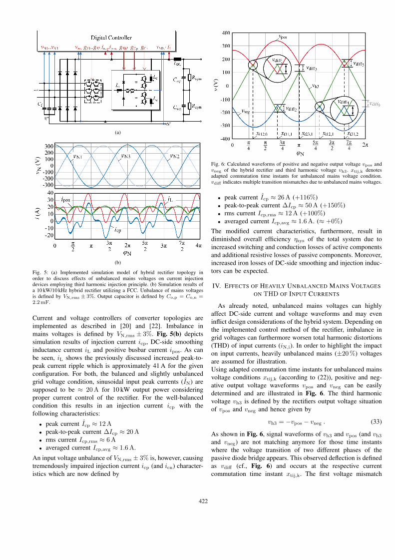
Fig. 5: (a) Implemented simulation model of hybrid rectifier topology inorder to discuss effects of unbalanced mains voltages on current injectiondevices employing third harmonic injection principle. (b) Simulation results ofa 10 kW/10 kHz hybrid rectifier utilizing a FCC. Unbalance of mains voltagesis defined by VN,rms ± 3%. Output capacitor is defined by Co,p = Co,n =2.2mF.
Current and voltage controllers of converter topologies areimplemented as described in [20] and [22]. Imbalance inmains voltages is defined by VN,rms ± 3%. Fig. 5(b) depictssimulation results of injection current icp, DC-side smoothinginductance current iL and positive busbar current ipos. As canbe seen, iL shows the previously discussed increased peak-to-peak current ripple which is approximately 41 A for the givenconfiguration. For both, the balanced and slightly unbalancedgrid voltage condition, sinusoidal input peak currents (IN) aresupposed to be ≈ 20 A for 10 kW output power consideringproper current control of the rectifier. For the well-balancedcondition this results in an injection current icp with thefollowing characteristics:
• peak current Icp ≈ 12 A• peak-to-peak current ∆Icp ≈ 20 A• rms current Icp,rms ≈ 6 A• averaged current Icp,avg ≈ 1.6 A.
An input voltage unbalance of VN,rms ± 3% is, however, causingtremendously impaired injection current icp (and icn) character-istics which are now defined by
Fig. 6: Calculated waveforms of positive and negative output voltage vpos andvneg of the hybrid rectifier and third harmonic voltage vh3. xtij,k denotesadapted commutation time instants for unbalanced mains voltage condition.vdiff indicates multiple transition mismatches due to unbalanced mains voltages.
• peak current Icp ≈ 26 A (+116%)• peak-to-peak current ∆Icp ≈ 50 A (+150%)• rms current Icp,rms ≈ 12 A (+100%)• averaged current Icp,avg ≈ 1.6 A. (≈ +0%)
The modified current characteristics, furthermore, result indiminished overall efficiency ηsys of the total system due toincreased switching and conduction losses of active componentsand additional resistive losses of passive components. Moreover,increased iron losses of DC-side smoothing and injection induc-tors can be expected.
IV. EFFECTS OF HEAVILY UNBALANCED MAINS VOLTAGESON THD OF INPUT CURRENTS
As already noted, unbalanced mains voltages can highlyaffect DC-side current and voltage waveforms and may eveninflict design considerations of the hybrid system. Depending onthe implemented control method of the rectifier, imbalance ingrid voltages can furthermore worsen total harmonic distortions(THD) of input currents (iN,i). In order to highlight the impacton input currents, heavily unbalanced mains (±20 %) voltagesare assumed for illustration.Using adapted commutation time instants for unbalanced mainsvoltage conditions xtij,k (according to (22)), positive and neg-ative output voltage waveforms vpos and vneg can be easilydetermined and are illustrated in Fig. 6. The third harmonicvoltage vh3 is defined by the rectifiers output voltage situationof vpos and vneg and hence given by
vh3 = −vpos − vneg . (33)
As shown in Fig. 6, signal waveforms of vh3 and vpos (and vh3
and vneg) are not matching anymore for those time instantswhere the voltage transition of two different phases of thepassive diode bridge appears. This observed deflection is definedas vdiff (cf., Fig. 6) and occurs at the respective currentcommutation time instant xtij,k. The first voltage mismatch
422

Fig. 7: Simulation results of a 10 kW/10 kHz hybrid rectifier utilizing a FCC forheavily unbalanced mains voltages (VN,rms ± 20%). Filtered AC input currentsiNi,f result in THDi,1 = 10.2%, THDi,2 = 15.5% and THDi,1 = 12.86%
vdiff,1 can be assessed by
vdiff,1 = vpos (xt12,0)− vh3 (xt12,0) (34)
with vh3 (xt12,0) = −vpos (xt12,0) − vneg (xt12,0). vdiff,1 cantherefore be computed to
vdiff,1 =
√3
2
2VN1VN2 − VN1VN3 − VN2VN3√V 2
N1 + VN1VN2 + V 2N2
. (35)
All remaining voltage deviations vdiff,2 − vdiff,6 can be calcu-lated similarly under consideration of (34). It has to be notedthat vdiff,1 = vdiff,4, vdiff,2 = vdiff,5 and vdiff,3 = vdiff,6.These voltage deviations are of major importance for generationof current and voltage controller reference signals of the activecurrent injection cell. In conventional active rectifier circuits[18], the reference currents are often generated by a superim-posed voltage controller which indirectly determines the powerdemand by measuring the voltage of the dc-link capacitor. Theoutput voltage of the proposed rectifier system is, however, notcontrolled, but is dependent on the mains and load situationand is even not measured. The power transferred from themains to the output of the rectifier is not dependent on thecurrent shape and can therefore be determined by measurementin both operating modes, operating in diode mode as well asfor active current shaping using the FCC. The power demandcan be determined using the mains voltages (vN1, vN2, vN3) andDC-side current iL
p(t) = (vpos − vneg) iL . (36)
The equivalent conductance g∗e can now be calculated to
g∗e =Pin
V 2N1,rms + V 2
N2,rms + V 2N3,rms
. (37)
Pin is the low-pass filtered constant value of instantaneouspower demand p(t). g∗e is finally multiplied with the (calculated)voltages vpos and vneg in order to derive the reference currents
TABLE II: Power Devices Selected for Implementation of the FCC Prototype.
Sia,b 1200V/40A IGBT, IKW40T120, InfineonSc p
n± 600V/20A IGBT, IKW20N60H3, Infineon
Dh3± 1200V/15A, STTH1512W, ST-MicroelectronicsCc p
n470µF/400V, EPCOS B43501-type
Lcp=Lcn=Lh3 3.2mH, Iron core 3UI60a, N = 123 turnsCF, CS 6.8µF/275VAC, MKP X2, ArcotronicsCo 2.2mF/400V, Felsic CO 39 A728848LDC 2.25mH, Iron core 2 x UI60aD1 −D6 35A/1600V, 36MT160, Vishay
i∗pos (= g∗evpos) and i∗neg. As
ipos + ih3 + ineg = 0 (38)
the same mismatch applicable for DC-side voltages vpos, vh3
and vneg is also valid for DC-side currents ipos, ih3 and ineg.The input currents are therefore supposed to show current stepsduring every current transition of the input side of the system.Simulation results of the discussed issues are illustrated in Fig. 7for heavily unbalanced mains voltages of VN1,rms = 276 V,VN2,rms = 230 V and VN3,rms = 184 V. Filtered AC input cur-rents iNi,f finally result in a total harmonic distortion ofTHDi,1 = 10.2 %, THDi,2 = 15.5 % and THDi,1 = 12.86 %which is significantly higher than the officially allowed 5 %according to IEEE standards.
V. EXPERIMENTAL RESULTS
Measurement results of the constructed 10 kW/10 kHz lab-oratory prototype for 50 Hz/400 VLL mains are illustrated inFig. 8. The applied components of the hybrid system are listedin TABLE II. Measurement taken from a three-phase grid atthe power electronics laboratory of the Vienna university oftechnology revealed a THDv of approximately 2 % and anmaximum grid unbalance of less than 1 %. A detailed char-acterisation of fundamental components and higher harmonicsof all three mains phases are listed TABLE III. All results havebeen obtained by a PM-300 power analyser.Fig. 8 clearly reveals the discussed superimposed 100 Hz com-ponent of iL which obviously results in an increased peak-to-peak current ripple ∆IL,pkpk = 21 A. This furthermore leadsto an increased injection current icp showing a peak-to-peakcurrent ripple ∆Icp,pkpk of 28 A instead of the expected 21 A.
VI. CONCLUSION
Effects of unbalanced AC-side mains voltages on passivethree-phase rectifier systems, which are utilizing a currentinjection device (in order to guarantee sinusoidal input currents),have been analysed in this paper. It is shown that even slightlyimbalanced mains voltages may result in significantly increasedDC-side smoothing inductance (LDC) current ripple and henceinjection inductance (Lc) current ripple. Reduced efficiencyand even overload condition of the system can therefore beexpected due to higher switching and conduction losses of activecomponents, as well as additional resistive losses of passivecomponents and iron losses of inductors.
423

TABLE III: Measured Mains Voltage Harmonics (Location: Vienna Universityof Technology - Power Electronics Laboratory).
Measured Harmonic Componentsof Mains Voltages
vN1 vN2 vN3
Fund. Comp. 231.3 V 230.5 V 229.9 V3rd ord. harm. 0.33% 0.09% 0.41%5th ord. harm. 2.22% 2.19% 2.06%7th ord. harm. 1.32% 1.22% 1.29%9th ord. harm. 0.22% 0.37% 0.43%11th ord. harm. 0.22% 0.41% 0.33%13th ord. harm. 0.47% 0.56% 0.53%15th ord. harm. 0.14% 0.21% 0.31%17th ord. harm. 0.16% 0.23% 0.19%
Fig. 8: Measured currents ipos, iL and icp for an output power of Po = 10 kWand fundamental mains voltage components of VN1,rms = 231.3V,VN2,rms = 230.5V and VN3,rms = 229.9V.
The output voltage of the system (vo) is characterized by asuperimposed 100 Hz voltage spectral component in addition toits preliminary dominant DC and 300 Hz voltage components.It is furthermore shown, that imbalance in mains voltagesimpairs input currents total harmonic distortion characteristics.An appropriate control strategy for hybrid rectifiers employingthird harmonic injection considering heavily unbalanced mainsvoltage condition is not discussed up to now and should hencebe topic of further research.
REFERENCES
[1] N. Mohan, “A Novel Approach to Minimize Line-Current Harmonics inInterfacing Power Electronics Equipment with 3-Phase Utility Systems,”IEEE Transactions on Power Delivery, vol. 8, no. 3, pp. 1395–1401, 1993.
[2] P. Pejovic and Z. Janda, “Optimal Current Programming in Three-PhaseHigh-Power-Factor Rectifier Based on Two Boost Converters,” IEEETransactions on Power Electronics, vol. 13, no. 6, pp. 1152–1163, 1998.
[3] T.B. Soeiro, T. Friedli, and J.W. Kolar, “Swiss Rectifier — A Novel Three-Phase Buck-Type PFC Topology for Electric Vehicle Battery Charging,”in Proceedings of the Twenty-Seventh Annual IEEE Applied Power Elec-tronics Conference and Exposition (APEC), 2012, pp. 2617–2624.
[4] J.W. Kolar, H. Ertl, and Franz C. Zach, “A novel three-phase single-switchdiscontinuous-mode AC-DC buck-boost converter with high-quality inputcurrent waveforms and isolated output,” vol. 9, no. 2, pp. 160–172, 1994.
[5] F. Stogerer, J. Minibock, and J.W. Kolar, “Implementation of a NovelControl Concept for Reliable Operation of a VIENNA Rectifier underHeavily Unbalanced Mains Voltage Conditions,” in Proceedings of theIEEE 32nd Annual Power Electronics Specialists Conference (PESC),2001, vol. 3, pp. 1333–1338.
[6] J. Minibock, R. Greul, and J.W. Kolar, “A Novel Control Concept forOperating a Two-Stage Delta-Rectifier-Based Telecommunications PowerSupply Module under Heavily Unbalanced Mains Voltage Conditions,” inProceedings of the Seventeenth Annual IEEE Applied Power ElectronicsConference and Exposition (APEC), 2002, vol. 2, pp. 716–721.
[7] M. Baumann and J.W. Kolar, “A Novel Control Concept for ReliableOperation of a Three-Phase Three-Switch Buck-Type Unity-Power-FactorRectifier with Integrated Boost Output Stage under Heavily UnbalancedMains Condition,” IEEE Transactions on Industrial Electronics, vol. 52,no. 2, pp. 399–409, 2005.
[8] H.M. Teshnizi, A. Moallem, M.-R. Zolghadri, and M. Ferdowsi, “A Dual-Frame Hybrid Vector Control of Vector Modulated VIENNA I Rectifierfor Unity Power Factor Operation under Unbalanced Mains Condition,”in Proceedings of Twenty-Third Annual IEEE Applied Power ElectronicsConference and Exposition (APEC), 2008, pp. 1402–1408.
[9] Lei Shang, Dan Sun, Jiabing Hu, and Yikang He, “Predictive Direct PowerControl of Grid-Connected Voltage-Sourced Converters under UnbalancedGrid Voltage Conditions,” in Proceedings of the International Conferenceon Electrical Machines and Systems (ICEMS), 2009, pp. 1–5.
[10] Zheng Zheng and Zhang Zhen-hua, “Research of Direct Power Controlfor PWM Rectifier under Unbalanced Grid Voltage,” in Proceedings ofthe 25th Chinese Control and Decision Conference (CCDC), 2013, pp.3607–3612.
[11] Y. Zhang, C. Qu, Z. Li, and Yingchao Zhang, “Direct Power Controlof PWM Rectifier under Unbalanced Grid Voltage,” in Proceedings ofthe 17th International Conference on Electrical Machines and Systems(ICEMS), 2014, pp. 3199–3204.
[12] Y. Zhang and C. Qu, “Direct Power Control of a Pulse Width Modu-lation Rectifier Using Space Vector Modulation Under Unbalanced GridVoltage,” IEEE Transactions on Power Electronics, 2014, Early Access.
[13] Y. Zhang and C. Qu, “Table-Based Direct Power Control for Three-PhaseAC/DC Converters Under Unbalanced Grid Voltages,” IEEE Transactionson Power Electronics, 2015, Early Access.
[14] Y. Zhang and C. Qu, “Model Predictive Direct Power Control of PWMRectifier Under Unbalanced Network Conditions,” IEEE Transactions onIndustrial Electronics, 2015, Early Access.
[15] H. Abaali, M.T. Lamchich, and M. Raoufi, “The Three Phase Shunt ActiveFilters for the Harmonics Compensation under Distorted and UnbalancedMains Voltages Conditions,” in Proceedings of the IEEE InternationalConference onIndustrial Technology (ICIT), 2004, vol. 1, pp. 558–563.
[16] D. De and V. Ramanarayanan, “An Active Shunt Compensator for Re-active, Unbalanced and Harmonic Loads under Balanced and UnbalancedGrid Voltage Conditions,” in Proceedings of the International Conferenceon Power Electronics, Drives and Energy Systems (PEDES), 2010, pp.1–6.
[17] X. Liu, F. Blaabjerg, P.C. Loh, and P. Wang, “Carrier-Based ModulationStrategy and Its Implementation for Indirect Matrix Converter underUnbalanced Grid Voltage Conditions,” in Proceedings of the 15th Interna-tional Power Electronics and Motion Control Conference (EPE/PEMC),2012.
[18] J.W. Kolar and T. Friedli, “The Essence of Three-Phase PFC RectifierSystems—Part I,” IEEE Transactions on Power Electronics, vol. 28, no.1, pp. 176–198, 2013.
[19] M. Hartmann and R. Fehringer, “Active Three-Phase Rectifier SystemUsing a “Flying” Converter Cell,” in Proceedings of the InternationalEnergy Conference and Exhibition (ENERGYCON), 2012, pp. 82–89.
[20] M. Hartmann, R. Fehringer, M. Makoschitz, and H. Ertl, “Designand Experimental Verification of a Third Harmonic Injection RectifierCircuit Using a Flying Converter Cell,” in Proceedings of the Twenty-Ninth Annual IEEE Applied Power Electronics Conference and Exposition(APEC), 2014, pp. 920–927.
[21] M. Makoschitz, M. Hartmann, and H. Ertl, “Analysis of a Three-PhaseFlying Converter Cell Rectifier Operating in Light/No-Load Condition,”in Proceedings of the 30th Annual IEEE Applied Power ElectronicsConference and Exposition (APEC), 2015, pp. 920–927.
[22] M. Makoschitz, M. Hartmann, H. Ertl, and R. Fehringer, “DC VoltageBalancing of Flying Converter Cell,” in Proceedings of the EnergyConversion Congress and Exposition (ECCE), 2014, pp. 4071–4078.
424
Powered by TCPDF (www.tcpdf.org)