00 UM MSI-RM2B en - Custom Automation & Industrial … 5.1: Guarding a paternoster shelf with MLC...
25
MSI-RM2B Safety Relays SAFE IMPLEMENTATION AND OPERATION Original operating instructions EN 2013/10 - 50124437 We reserve the right to make technical changes
-
Upload
dangkhuong -
Category
Documents
-
view
220 -
download
0
Transcript of 00 UM MSI-RM2B en - Custom Automation & Industrial … 5.1: Guarding a paternoster shelf with MLC...

MSI-RM2BSafety Relays
S A F E I M P L E M E N T A T I O N A N D O P E R A T I O NO r i g i n a l o p e r a t i n g i n s t r u c t i o n s
EN 2
013/
10 -
5012
4437
We
rese
rve
the
right
to
mak
e te
chni
cal c
hang
es

Leuze electronic MSI-RM2B 2
© 2013Leuze electronic GmbH + Co. KGIn der Braike 1D-73277 Owen / GermanyPhone: +49 7021 573-0Fax: +49 7021 573-199http://[email protected]

Leuze electronic MSI-RM2B 3
1 About this document. . . . . . . . . . . . . . . . . . . . . . . . . . . . . . . . . . . . . . . . . . . . . . . . . . . . 41.1 Used symbols and signal words . . . . . . . . . . . . . . . . . . . . . . . . . . . . . . . . . . . . . . . . . . . . . . . . . . . . 41.2 Checklists . . . . . . . . . . . . . . . . . . . . . . . . . . . . . . . . . . . . . . . . . . . . . . . . . . . . . . . . . . . . . . . . . . . . . 4
2 Safety . . . . . . . . . . . . . . . . . . . . . . . . . . . . . . . . . . . . . . . . . . . . . . . . . . . . . . . . . . . . . . . 52.1 Approved purpose and foreseeable improper operation . . . . . . . . . . . . . . . . . . . . . . . . . . . . . . . . . . 52.1.1 Proper use . . . . . . . . . . . . . . . . . . . . . . . . . . . . . . . . . . . . . . . . . . . . . . . . . . . . . . . . . . . . . . . . . . . . . 52.1.2 Foreseeable misuse . . . . . . . . . . . . . . . . . . . . . . . . . . . . . . . . . . . . . . . . . . . . . . . . . . . . . . . . . . . . . 62.2 Competent persons . . . . . . . . . . . . . . . . . . . . . . . . . . . . . . . . . . . . . . . . . . . . . . . . . . . . . . . . . . . . . . 62.3 Responsibility for safety. . . . . . . . . . . . . . . . . . . . . . . . . . . . . . . . . . . . . . . . . . . . . . . . . . . . . . . . . . . 62.4 Disclaimer . . . . . . . . . . . . . . . . . . . . . . . . . . . . . . . . . . . . . . . . . . . . . . . . . . . . . . . . . . . . . . . . . . . . . 7
3 Device description . . . . . . . . . . . . . . . . . . . . . . . . . . . . . . . . . . . . . . . . . . . . . . . . . . . . . 83.1 System overview . . . . . . . . . . . . . . . . . . . . . . . . . . . . . . . . . . . . . . . . . . . . . . . . . . . . . . . . . . . . . . . . 93.2 Display elements . . . . . . . . . . . . . . . . . . . . . . . . . . . . . . . . . . . . . . . . . . . . . . . . . . . . . . . . . . . . . . . . 9
4 Functions . . . . . . . . . . . . . . . . . . . . . . . . . . . . . . . . . . . . . . . . . . . . . . . . . . . . . . . . . . . 10
5 Applications . . . . . . . . . . . . . . . . . . . . . . . . . . . . . . . . . . . . . . . . . . . . . . . . . . . . . . . . . 11
6 Mounting. . . . . . . . . . . . . . . . . . . . . . . . . . . . . . . . . . . . . . . . . . . . . . . . . . . . . . . . . . . . 12
7 Electrical connection . . . . . . . . . . . . . . . . . . . . . . . . . . . . . . . . . . . . . . . . . . . . . . . . . . 137.1 Terminal assignments . . . . . . . . . . . . . . . . . . . . . . . . . . . . . . . . . . . . . . . . . . . . . . . . . . . . . . . . . . . 137.2 Circuit diagram examples . . . . . . . . . . . . . . . . . . . . . . . . . . . . . . . . . . . . . . . . . . . . . . . . . . . . . . . . 14
8 Starting up the device. . . . . . . . . . . . . . . . . . . . . . . . . . . . . . . . . . . . . . . . . . . . . . . . . . 158.1 Switching on . . . . . . . . . . . . . . . . . . . . . . . . . . . . . . . . . . . . . . . . . . . . . . . . . . . . . . . . . . . . . . . . . . 15
9 Testing . . . . . . . . . . . . . . . . . . . . . . . . . . . . . . . . . . . . . . . . . . . . . . . . . . . . . . . . . . . . . 169.1 Before the initial start-up and following modifications . . . . . . . . . . . . . . . . . . . . . . . . . . . . . . . . . . . 169.1.1 Checklist – initial start-up . . . . . . . . . . . . . . . . . . . . . . . . . . . . . . . . . . . . . . . . . . . . . . . . . . . . . . . . . 169.2 To be performed periodically by a competent person . . . . . . . . . . . . . . . . . . . . . . . . . . . . . . . . . . . 189.3 To be performed daily by the operating personnel . . . . . . . . . . . . . . . . . . . . . . . . . . . . . . . . . . . . . 189.3.1 Check list – daily or at change of shift . . . . . . . . . . . . . . . . . . . . . . . . . . . . . . . . . . . . . . . . . . . . . . . 18
10 Maintenance. . . . . . . . . . . . . . . . . . . . . . . . . . . . . . . . . . . . . . . . . . . . . . . . . . . . . . . . . 19
11 Disposing . . . . . . . . . . . . . . . . . . . . . . . . . . . . . . . . . . . . . . . . . . . . . . . . . . . . . . . . . . . 20
12 Service and support . . . . . . . . . . . . . . . . . . . . . . . . . . . . . . . . . . . . . . . . . . . . . . . . . . . 21
13 Technical data . . . . . . . . . . . . . . . . . . . . . . . . . . . . . . . . . . . . . . . . . . . . . . . . . . . . . . . 2213.1 Dimensions . . . . . . . . . . . . . . . . . . . . . . . . . . . . . . . . . . . . . . . . . . . . . . . . . . . . . . . . . . . . . . . . . . . 23
14 Order guide . . . . . . . . . . . . . . . . . . . . . . . . . . . . . . . . . . . . . . . . . . . . . . . . . . . . . . . . . 24
15 EC Declaration of Conformity. . . . . . . . . . . . . . . . . . . . . . . . . . . . . . . . . . . . . . . . . . . . 25
About this document
Leuze electronic MSI-RM2B 4
1 About this document
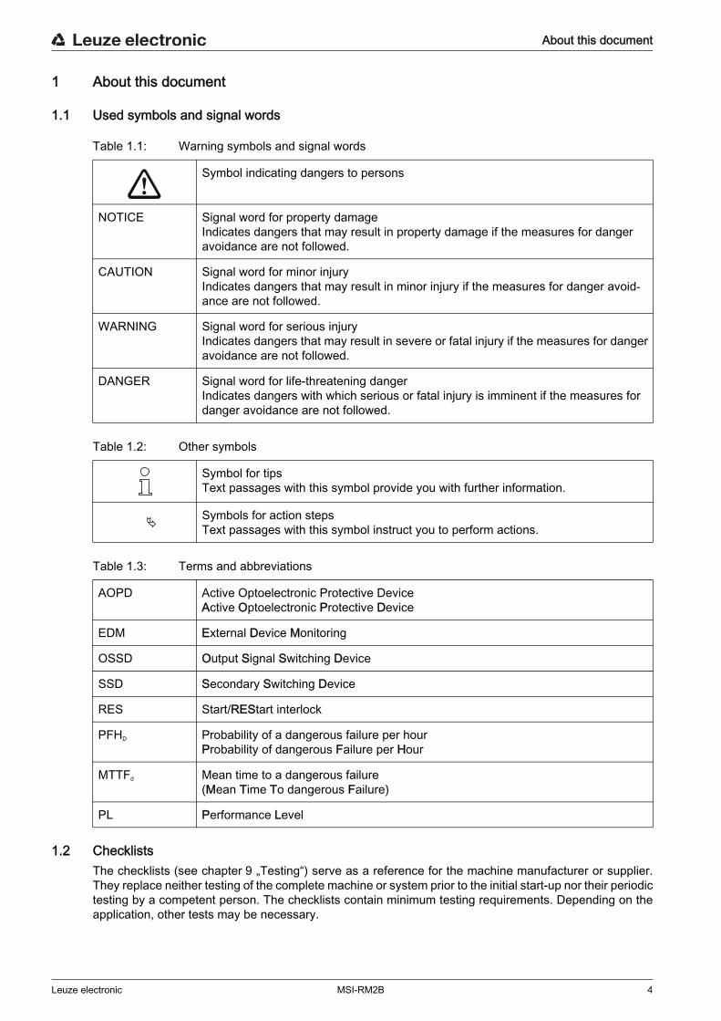
1.1 Used symbols and signal words
Table 1.1: Warning symbols and signal words
Table 1.2: Other symbols
Table 1.3: Terms and abbreviations
1.2 ChecklistsThe checklists (see chapter 9 „Testing“) serve as a reference for the machine manufacturer or supplier. They replace neither testing of the complete machine or system prior to the initial start-up nor their periodic testing by a competent person. The checklists contain minimum testing requirements. Depending on the application, other tests may be necessary.
Symbol indicating dangers to persons
NOTICE Signal word for property damageIndicates dangers that may result in property damage if the measures for danger avoidance are not followed.
CAUTION Signal word for minor injuryIndicates dangers that may result in minor injury if the measures for danger avoid-ance are not followed.
WARNING Signal word for serious injuryIndicates dangers that may result in severe or fatal injury if the measures for danger avoidance are not followed.
DANGER Signal word for life-threatening dangerIndicates dangers with which serious or fatal injury is imminent if the measures for danger avoidance are not followed.
Symbol for tipsText passages with this symbol provide you with further information.
Symbols for action stepsText passages with this symbol instruct you to perform actions.
AOPD Active Optoelectronic Protective DeviceActive Optoelectronic Protective Device
EDM External Device Monitoring
OSSD Output Signal Switching Device
SSD Secondary Switching Device
RES Start/REStart interlock
PFHD Probability of a dangerous failure per hourProbability of dangerous Failure per Hour
MTTFd Mean time to a dangerous failure(Mean Time To dangerous Failure)
PL Performance Level

Safety
Leuze electronic MSI-RM2B 5
2 SafetyBefore using the safety relay, a risk evaluation must be performed according to valid standards (e.g. EN ISO 12100, ISO 13849-1, EN/IEC 61508, EN/IEC 62061). The result of the risk assessment deter- mines the required safety level of the safety relay (see table 13.1). For mounting, operating and testing, this document as well as all applicable national and international standards, regulations, rules and direc- tives must be observed. Relevant and supplied documents must be observed and handed to the affected personnel. Before working with the safety relay, completely read and understand the documents applicable to your
task.In particular, the following national and international legal regulations apply for the start-up, technical inspections and work with safety relays:
• Machinery directive 2006/42/EC• Low voltage directive 2006/95/EC• Electromagnetic compatibility 2004/108/EC• Use of Work Equipment Directive 89/655/EEC supplemented by Directive 2009/104/EC• OSHA 1910 Subpart 0• Safety regulations• Accident-prevention regulations and safety rules• Industrial safety regulation and employment protection act• Product Safety Act
2.1 Approved purpose and foreseeable improper operation
2.1.1 Proper use
For safety-related information you may also contact the local authorities (e.g., industrial inspec- torate, employer's liability insurance association, labor inspectorate, occupational safety and health authority).
DANGERElectrically live systems pose a risk of electric shock! During all conversions, maintenance work and inspections, make certain that the voltage supply is
interrupted and protected against being restarted again. Only have work on the electrical system and electronics performed by a competent person.
WARNINGA running machine may result in serious injury!Make certain that the safety relay is correctly connected and that the protective function of the protec-
tive device is ensured.Make certain that, during all conversions, maintenance work and inspections, the system is securely
shut down and protected against being restarted.

Safety
Leuze electronic MSI-RM2B 6
Only if the safety relay is correctly connected and correctly started up is the protective function of the protective device ensured. To prevent misuse and resulting dangers, the following must be observed:
• These operating instructions are included in the documentation of the system on which the protective device is mounted and are available to the operating personnel at all times.
• The safety relay is used as a safety relay in combination with safety sensors or other safety relays for safeguarding danger zones or point of operations in machines and systems.
• The safety relay must only be used after it has been selected in accordance with the respectively applicable instructions and relevant standards, rules and regulations regarding labor protection and safety at work, and after it has been installed, connected, checked and commissioned by a compe-tent person.
• The safety relay must only be connected and commissioned in accordance with its specifications (technical data, environmental conditions, etc.).
• The “Reset” acknowledgment button for unlocking the start/restart interlock must be located outside of the danger zone.
• The entire danger zone must be visible from the installation site of the acknowledgment button.• The safety relay must be selected so that its safety-related capability meets or exceeds the required
Performance Level PL ascertained in the risk assessment (see table 13.1).• The machine or system control must be electrically influenceable so that a switch command sent by
the safety relay results in the immediate shutdown of the dangerous movement.• The construction of the safety relay must not be altered. When manipulating the safety relay, the pro-
tective function is no longer guaranteed. Manipulating the safety relay also voids all warranty claims against the manufacturer of the safety relay.
• The safety relay must be tested regularly by a competent person (see chapter 9 „Testing“).• The safety relay must be exchanged after a maximum of 20 years. Repairs or the exchange of parts
subject to wear and tear do not extend the service life.• The safety relay does not have a safety category or Performance Level of its own. When used as
intended, it can, however, satisfy the prerequisites for achieving the safety category and Perfor-mance Level that corresponds to the connected safety sensor or safety relay.
• The connected safety sensors or safety relays must be equipped with OSSDs in cross-connection- and short-circuit-monitored design (EDM). The contactor monitoring function must check the closing of the signal circuit before the OSSDs are switched on and the opening of the same after switch-on has occurred.
2.1.2 Foreseeable misuseAny use other than that defined under the “Approved purpose” or which goes beyond that use is consid- ered improper use.
Alone, the safety relay is not a complete protective device. It is not suitable for use in the following cases:• in explosive or easily flammable atmospheres.• on machines or systems with long stopping times.
2.2 Competent persons
Prerequisites for competent persons:• They have a suitable technical education.• They know the rules and regulations for labor protection, safety at work and safety technology and
can assess the safety of the machine.• They know the instructions for the safety relay and the machine.• They have been instructed by the responsible person on the mounting and operation of the machine
and of the safety relay.
2.3 Responsibility for safetyManufacturer and operating company must ensure that the machine and implemented safety relay func- tion properly and that all affected persons are adequately informed and trained.The type and content of all imparted information must not lead to unsafe actions by users.

Safety
Leuze electronic MSI-RM2B 7
The manufacturer of the machine is responsible for:• Safe machine construction• Safe implementation of the safety relay• Imparting all relevant information to the operating company• Adhering to all regulations and directives for the safe starting-up of the machine
The operator of the machine is responsible for:• Instructing the operating personnel• Maintaining the safe operation of the machine• Adhering to all regulations and directives for labor protection and safety at work• Regular testing by competent persons
2.4 DisclaimerLeuze electronic GmbH + Co. KG is not liable in the following cases:
• Safety relay is not used as intended• Safety notices are not adhered to.• Reasonably foreseeable misuse is not taken into account.• Mounting and electrical connection are not properly performed.• Proper function is not tested (see chapter 9 „Testing“).• Changes (e.g., constructional) are made to the safety relay

Device description
Leuze electronic MSI-RM2B 8
3 Device descriptionThe MSI-RM2B relay module is suitable for use as a two-channel sequential circuit for safe protective devices with 2 OSSDs and contactor monitoring (EDM).
Figure 3.3: Internal circuit diagram of the MSI-RM2B
Figure 3.1: MSI-RM2B with screw terminals Figure 3.2: MSI-RM2B with spring-cage terminals
14 12 11
24 22 21
K1-B
K2-B
CH1
CH2
Y1
Y2
K1
K2
B3
A2B1
K1-A
K2-A
rein
forc
ed is
olat
ion
(IE
C 4
39-1
)
Leuze electronic MSI- RM2B

Device description
Leuze electronic MSI-RM2B 9
3.1 System overview• NC contact as signal circuit for contactor monitoring (EDM)• Monitoring of external contactors in the signal circuit• 2 release circuits (changeovers)• LED displays, K1 and K2• Operating voltage 24 V DC• Housing width, 17.5 mm• Removable connection terminal blocks (screw terminals, spring-cage terminals)
3.2 Display elementsThe display elements of the safety relay simplify the start-up and fault analysis.
1 LED “K1”2 LED “K2”
Figure 3.4: Display elements of the MSI-RM2B
Table 3.1: Meaning of the LEDs
1
2
LED Color Description
K1 green Relay K1 picked up
K2 green Relay K2 picked up
Functions
Leuze electronic MSI-RM2B 10
4 FunctionsThe MSI-RM2B safety relay converts the electronic safety-related switching outputs of safety sensors or safety relays into potential-free, positive-guided contacts with signaling path. It can be integrated into the contactor monitoring (EDM) via the signaling path.

Applications
Leuze electronic MSI-RM2B 11
5 Applications
Figure 5.1: Guarding a paternoster shelf with MLC safety light curtain and MSI-RM2B relay module

Mounting
Leuze electronic MSI-RM2B 12
6 Mounting
The safety relay is intended for mounting on a DIN rail in a cabinet.
Prerequisites for mounting:• Cabinet with appropriate protection rating (at least IP54).• Sufficient space on the DIN rail.
Snap the safety relay onto the DIN rail.The safety relay can be connected to the safety sensors.
WARNINGImproper mounting may result in serious injury!The protective function of the safety relay is only ensured if appropriately and professionally mounted for the respective, intended area of application. Only allow competent persons to install the safety relay. Observe the relevant standards, regulations and these instructions.

Electrical connection
Leuze electronic MSI-RM2B 13
7 Electrical connection
The following must be observed for the current supply of the safety relay:• Supply voltage 24 V DC ±20 %.• Safe mains separation acc. to EN/IEC 60742 possible.• A corresponding power supply unit handles interruptions of the supply voltage up to 10 ms in dura-
tion acc. to EN/IEC 61496-1.
The following conditions apply for the electrical connection:• The safety relay is to be integrated in the control acc. to ISO 13849-1.• No safety-relevant signals are switched via the message outputs.• There are always two switching contacts integrated in the system switch-off circuit.• Relay switching contacts are fused/protected externally according to their specifications.
Connecting the signal lines
For reliable and touch-safe contacts, isolate the connection ends as follows:• Screw terminals: 7 mm• Spring-cage terminals: 8 mm
7.1 Terminal assignments
Connected to the safety relay are 12 numbered terminals to which the cables for the various functions are connected.
DANGERRisk of death by electric shock!Depending on external wiring, dangerous voltages may be present at the switching outputs. During all work at the electrical system or electronics, make certain that each voltage supply has been
interrupted and protected against being restarted.
WARNINGImproper electrical connection may result in serious injury! Only allow competent persons to perform the electrical connection.Make certain that supply and signal lines are laid separately from power lines. Use appropriate spark extinction for contactors in the cabinet. Observe the installation notices and operating instructions of the products that are to be connected via
the safety relay (drive motors, brakes, etc.).
WARNINGSelecting the wrong functions may result in serious accidents! Always connect light beam safety devices to an external safety relay and activate the restart interlock. For access guarding, make certain that the restart interlock cannot be unlocked from within the danger
zone but that the danger zone can be viewed from the acknowledgment button (Reset). Select the functions so that the safety relay is used as intended (see chapter 2.1 „Approved purpose
and foreseeable improper operation“).

Electrical connection
Leuze electronic MSI-RM2B 14
Table 7.1: Terminal assignments
7.2 Circuit diagram examples
* Spark extinction circuit, suitable spark extinction providedFigure 7.1: MSI-RM2B safety relay with MLC 500 / MLC 300 safety light curtain
Terminal MSI-RM2B
22 Relay contact 2 IN, NC contact
24 Relay contact 2 IN, NO contact
11 Relay contact 1 OUT
Y1 Feedback circuit (EDM)
n.c. n.c.
Y2 Feedback circuit (EDM)
A2 0 V
B1 Sensor input channel 1, 24 V
B3 Sensor input channel 2, 24 V
14 Relay contact 1 IN, NO contact
21 Relay contact 2 OUT
12 Relay contact 1 IN, NC contact
ED
M
Var. A
Var. B
OS
SD
1
MSI-RM2B
OS
SD
2
Sta
rt
MLC520R / MLC320R
Res
tart
0V FE
FE
0V
MLC500T / MLC300T
+24
V
n.c.
Tes
t
+24
V
WH
A1
A2-K3
A1
A2-K4
PK
GN
1
2
1
2
BU
SH
8
-W1 BU
SH-W2
-S1
A25
14B36 Y1
BN
B1
4 -A3
11
3 12 22
YE
-K4
-K3
21Y2
-W1 BK
BN
5
-W2
7
21-A24
3
21-A1 24
GY
-K3 -K4-K4
-K3
PE
+24V
0V
+24V
PE0V
L+L+
L- L-
RE
S a
ctiv
e
* *

Starting up the device
Leuze electronic MSI-RM2B 15
8 Starting up the device
Prerequisites:• Light beam safety device and safety relay were mounted and connected in accordance with the
respective instructions.• Operating personnel were instructed on proper use.• Dangerous process was switched off and the system has been protected against being restarted
again. During start-up, test the function of the safety relay (see chapter 9 „Testing“).
8.1 Switching on
Requirements for the supply voltage (power supply unit):• Safe mains separation is ensured (acc. to EN/IEC 60742).• Changes and interruptions of the supply voltage are handled (acc. to EN/IEC 61496-1).• The start/restart interlock function of the connected safety sensors or safety relays is activated.
Switch on the current supply.The safety relay is ready for use.
WARNINGImproper use of the safety relay may result in serious injury!Make certain that the entire device and the integration of the optoelectronic protective device was
inspected by competent and instructed persons.Make certain that a dangerous process can only be started while the safety devices are switched on.

Testing
Leuze electronic MSI-RM2B 16
9 Testing
The safety relays must be exchanged after a maximum of 20 years. Always exchange the entire safety relay. For the tests, observe nationally applicable regulations. Document all tests in a comprehensible manner.
9.1 Before the initial start-up and following modifications
Acc. to IEC/TS 62046 and international regulations (e.g. EU directive 2009/104/EC), tests are to be performed by competent persons in the following situations:
• Prior to the initial start-up• Following modification to the machine• After longer machine downtime• After retrofitting or reconfiguring the safety device (safety relay and/or light beam safety device)
Test the effectiveness of the shutdown function in all operating modes of the machine acc. to the corre-sponding checklist (see chapter 9.1.1 „Checklist – initial start-up“).
Document all tests in a comprehensible manner and include the configuration of the safety relay along with the data for the safety and minimum distances in the documentation.
Before they begin work, train the operating personnel on their respective tasks. The training is the responsibility of the operating company.
Check whether the safety relay was correctly selected acc. to the locally applicable regulations and directives.
Check whether the safety relay is operated acc. to the specified environmental conditions (see chapter 13 „Technical data“).
Make certain that the safety relay is protected against overcurrent. Perform a visual inspection for damage and test the electrical function (see chapter 9.2 „To be per-
formed periodically by a competent person“).Minimum requirements for the power supply unit:
• Safe mains separation.• Power-failure bridging for at least 10 ms.
Not until proper function of the optoelectronic safety device and the safety relay is ascertained may they be integrated in the control circuit of the system.
9.1.1 Checklist – initial start-upInterval: once, prior to the initial start-up and following modificationTester: competent person
WARNINGA running machine may result in serious injury!Make certain that, during all conversions, maintenance work and inspections, the system is securely
shut down and protected against being restarted.
WARNINGUnpredictable machine behavior during initial start-up may result in serious injury!Make certain that there are no people in the danger zone.

Testing
Leuze electronic MSI-RM2B 17
Table 9.1: Checklist – initial start-up
Store this checklist with the machine documents.
Items on the check list Yes No
Were all safety directives and standards relevant to this machine type observed?
Does the Declaration of Conformity of the machine include a listing of these docu-ments?
Does the safety relay satisfy the safety-related capability (PL, SIL, category) as required by the risk assessment?
Circuit diagram: Are the safety-related switching outputs (OSSDs) integrated in the downstream machine control acc. to the required safety category?
Are the switching elements (e.g. contactors) with positive-guided contacts that are con-trolled by the safety relay monitored by a feedback circuit (EDM)?
Does the electrical wiring match the circuit diagrams?
Have the required protective measures against electrical shock been effectively imple-mented?
Has the maximum stopping time of the machine been remeasured and recorded in the machine documents?
Is the required safety distance (protective field to the next point of operation) main-tained?
Are all points of operation of the machine accessible only through the protective field? Are all additional protective devices (e.g. safety guards) correctly mounted and pro-tected against tampering?
Is the command device for triggering the start/restart interlock of the safety relay or the machine mounted in accordance with specifications?
Are safety relay, connecting cable, plug, protection caps and command devices undamaged and free of any signs of manipulation?
Has the effectiveness of the protective function been ensured for all operating modes of the machine by means of a function test?
Is the start/restart button for resetting the safety relay mounted outside of the danger zone in accordance with specifications in such a way that it cannot be reached from within the danger zone? Can the entire danger zone be seen from the place at which the start/restart button is installed?
Does the interruption of any given beam cause the dangerous movement to stop?
When the AOPD is separated from its supply voltage, does the dangerous movement stop, and, after the supply voltage has been restored, is it necessary to actuate the start/restart button to reset the machine?
Is the safety relay/light beam safety device effective during the entire dangerous move-ment of the machine?
Are the notices for daily testing of the safety sensor legible to the operating personnel and are they located in a highly visible location?
Is the muting indicator visibly mounted on the entry/exit path?

Testing
Leuze electronic MSI-RM2B 18
9.2 To be performed periodically by a competent personThe reliable interaction of safety sensor, safety relay and machine must be periodically tested in order to detect changes to the machine or impermissible tampering with the safety sensor. Testing intervals are determined by nationally applicable regulations (recommendation acc. to IEC/TS 62046: 6 months). Have all tests performed by competent persons. Observe the nationally applicable regulations and the time periods specified therein.
9.3 To be performed daily by the operating personnelThe function of the safety relay must be checked daily or at change of shifts, and at each change of machine operating mode as specified in the corresponding checklist (see chapter 9.3.1 „Check list – daily or at change of shift“) so that damages or unauthorized manipulations can be detected.
Stop the dangerous state. Check safety relay, transmitter, receiver and, if applicable, deflecting mirrors for damage or manipula-
tion. Interrupt the light beam of the light beam safety device from a position outside the danger zone and
ensure that the machine cannot be started with an interrupted light beam. Start the machine. Ensure that the dangerous state is stopped as soon as a light beam is interrupted.
9.3.1 Check list – daily or at change of shiftInterval: daily or at shift changeTester: authorized operating personnel or instructed person
Table 9.2: Check list – daily or at change of shift
WARNINGUnpredictable machine behavior during the test may result in serious injury!Make certain that there are no people in the danger zone.
WARNINGFaults during the daily inspection may result in serious injury!If you answer one of the items on the checklist (see table 9.2) with “no”, the machine must no longer be operated. Have the entire machine inspected by a competent person (see chapter 9.1 „Before the initial start-up
and following modifications“).
Items on the check list Yes No
Are safety relay, light beam safety device, connecting cables, plugs and command devices undamaged and free of any signs of manipulation?
Are all point of operations at the machine accessible only through one or more protec-tive fields of light beam safety devices?
Are all additional protective devices mounted correctly (e.g., safety guard)?
Does the start/restart interlock prevent the automatic start-up of the machine after the light beam safety device/safety relay has been switched on or activated?
Interrupt a light beam of the light beam safety device with a test object during opera-tion.Is the dangerous movement shut down immediately?

Maintenance
Leuze electronic MSI-RM2B 19
10 MaintenanceThe safety relay is maintenance-free.

Disposing
Leuze electronic MSI-RM2B 20
11 Disposing For disposal observe the applicable national regulations regarding electronic components.

Service and support
Leuze electronic MSI-RM2B 21
12 Service and support
Telephone number for 24-hour standby service:+49 (0) 7021 573-0
Service hotline: +49 (0) 8141 5350-111Monday to Thursday, 8.00 a.m. to 5.00 p.m. (UTC+1)Friday, 8.00 a.m. to 4.00 p.m. (UTC +1)
E-mail:[email protected]
Return address for repairs:Service CenterLeuze electronic GmbH + Co. KGIn der Braike 1D-73277 Owen / Germany
Technical data
Leuze electronic MSI-RM2B 22
13 Technical data
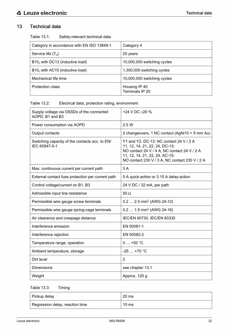
Table 13.1: Safety-relevant technical data
Table 13.2: Electrical data, protection rating, environment
Table 13.3: Timing
Category in accordance with EN ISO 13849-1 Category 4
Service life (TM) 20 years
B10d with DC13 (inductive load) 10,000,000 switching cycles
B10d with AC15 (inductive load) 1,300,000 switching cycles
Mechanical life time 10,000,000 switching cycles
Protection class Housing IP 40Terminals IP 20
Supply voltage via OSSDs of the connected AOPD, B1 and B3
+24 V DC 20 %
Power consumption via AOPD 2.5 W
Output contacts 2 changeovers, 1 NC contact (AgNi10 + 5 mm Au)
Switching capacity of the contacts acc. to EN/IEC 60947-5-1
Y1 and Y2, DC-13: NC contact 24 V / 2 A11, 12, 14, 21, 22, 24, DC-13: NO contact 24 V / 4 A, NC contact 24 V / 2 A11, 12, 14, 21, 22, 24, AC-15: NO contact 230 V / 3 A, NC contact 230 V / 2 A
Max. continuous current per current path 3 A
External contact fuse protection per current path 5 A quick-action or 3.15 A delay-action
Control voltage/current on B1, B3 24 V DC / 32 mA, per path
Admissible input line resistance 50
Permissible wire gauge screw terminals 0.2 … 2.5 mm2 (AWG 24-12)
Permissible wire gauge spring-cage terminals 0.2 … 1.5 mm2 (AWG 24-16)
Air clearance and creepage distance IEC/EN 60730, IEC/EN 60335
Interference emission EN 50081-1
Interference rejection EN 50082-2
Temperature range, operation 0 … +50 °C
Ambient temperature, storage -25 … +70 °C
Dirt level 2
Dimensions see chapter 13.1
Weight Approx. 120 g
Pickup delay 20 ms
Regression delay, reaction time 10 ms

Technical data
Leuze electronic MSI-RM2B 23
13.1 Dimensions
Figure 13.1: Dimensions MSI-RM2B-01
Figure 13.2: Dimensions MSI-RM2B-02
99.0
114.117.5
111.5
111
114.117.5
111.5
Order guide
Leuze electronic MSI-RM2B 24
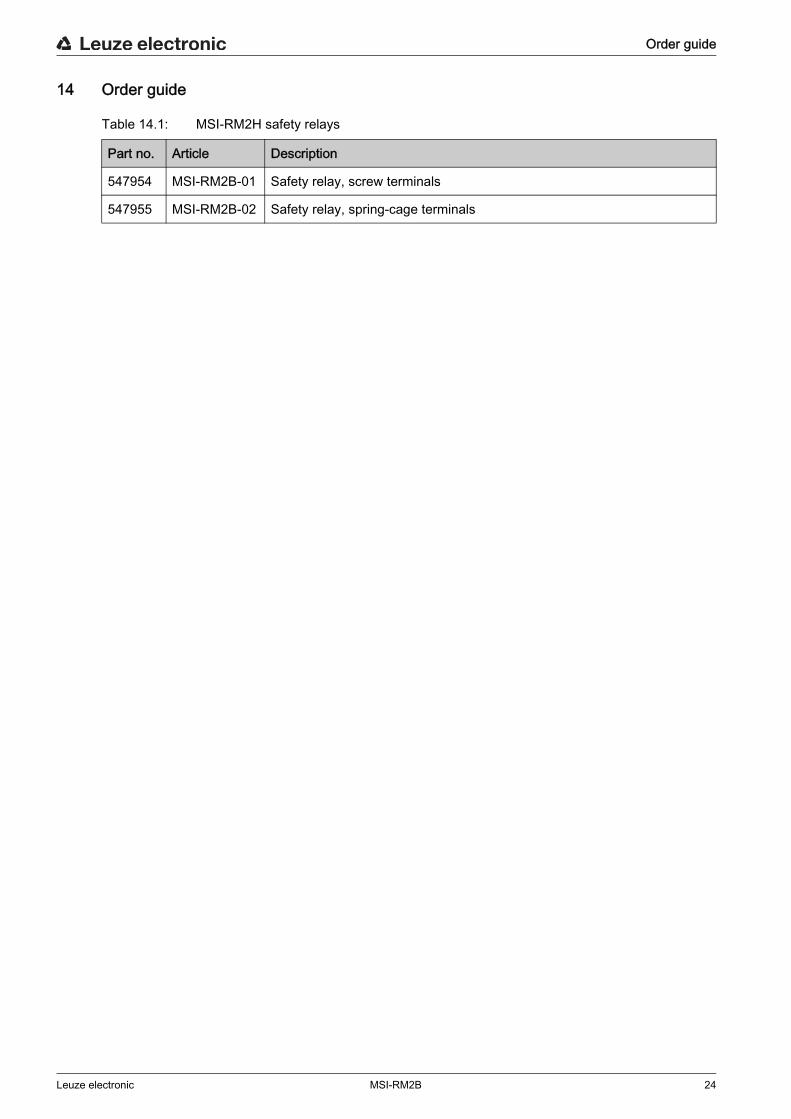
14 Order guide
Table 14.1: MSI-RM2H safety relays
Part no. Article Description
547954 MSI-RM2B-01 Safety relay, screw terminals
547955 MSI-RM2B-02 Safety relay, spring-cage terminals

EC Declaration of Conformity
Leuze electronic MSI-RM2B 25
15 EC Declaration of Conformity
Leuze electronic GmbH + Co. KG In der Braike 1 D-73277 Owen Telefon +49 (0) 7021 573-0 Telefax +49 (0) 7021 573-199 [email protected] www.leuze.com
Leuze electronic GmbH + Co. KG, Sitz Owen, Registergericht Stuttgart, HRA 230712 Persönlich haftende Gesellschafterin Leuze electronic Geschäftsführungs-GmbH, Sitz Owen, Registergericht Stuttgart, HRB 230550 Geschäftsführer: Ulrich Balbach, Dr. Matthias Kirchherr USt.-IdNr. DE 145912521 │ Zollnummer 2554232 Es gelten ausschließlich unsere aktuellen Verkaufs- und Lieferbedingungen Only our current Terms and Conditions of Sale and Delivery shall apply
Nr. 50124552 -2013/10
EG-KONFORMITÄTS-ERKLÄRUNG(ORIGINAL)
EC DECLARATION OF CONFORMITY
(ORIGINAL)
DECLARATION CE DE CONFORMITE
(ORIGINAL)
Der Hersteller The Manufacturer Le constructeur Leuze electronic GmbH + Co. KG
In der Braike 1, PO Box 1111 73277 Owen, Germany
erklärt, dass die nachfolgend aufgeführten Produkte den ein-schlägigen Anforderungen der genannten EG-Richtlinien und Normen entsprechen.
declares that the following listed products fulfil the relevant provi-sions of the mentioned EC Direc-tives and standards.
déclare que les produits identifiés suivants sont conformes aux directives CE et normes men-tionnées.
Produktbeschreibung: Description of product: Description de produit:
Relais-modul MSI-RM2B
Seriennummer siehe Typschild
Relay ModuleMSI-RM2B
Serial no. see name plates
Module relaisMSI-RM2B
N° série voir plaques signalétiques
Angewandte EG-Richtlinie(n): Applied EC Directive(s): Directive(s) CE appliquées:
2006/42/EG 2006/42/EC 2006/42/CE2004/108/EG 2004/108/EC 2004/108/CE2006/95/EG 2006/95/EC 2006/95/CE
Angewandte Normen: Applied standards: Normes appliquées: EN 55011:2007; EN 50178:1997; EN 61496-1:2004/A1 :2008; EN ISO 13849-1:2008 (Kat 4 PLe)
IEC 61508-1:2010/-2:2010/-4:2010 (SIL3)
Benannte Stelle / Baumusterprüfbescheinigung:
Notified Body / Certificate of Type Examination:
Organisme notifié / Attestation d'examen CE de type:
TÜV-SÜD PRODUCT SERVICE GmbHZertifizierungsstelle
Ridlerstraße 65 D-80339 München
/ Z10 10 03 22795 072
Bevollmächtigter für die Zusam-menstellung der technischen
Unterlagen:
Authorized person to compile the technical file:
Personne autorisée à constituer le dossier technique:
André Thieme; Leuze electronic GmbH + Co. KG Liebigstr. 4; 82256 Fuerstenfeldbruck; Germany
3102.01.10 ,newODatum / Date / Date Ulrich Balbach, Geschäftsführer / Director / Directeur

![Rob Paternoster [IEA14]](https://static.fdocuments.in/doc/165x107/586b64621a28abf6088b60f5/rob-paternoster-iea14.jpg)