>> Operator’s Manual. - smart USA · Let the fun begin! Take a moment to familiarize yourself...
220
>> Operator’s Manual. smart fortwo coupé and smart fortwo cabriolet
Transcript of >> Operator’s Manual. - smart USA · Let the fun begin! Take a moment to familiarize yourself...

>> Operator’s Manual.smart fortwo coupé and smart fortwo cabriolet

Symbols
Trademarks®:RESP® is a registered trademark of
Daimler.
The following symbols are found in thisOperator’s Manual:
* Optional equipment is identified withan asterisk. Since standard equipmentvaries between models, thedescriptions and illustrations in thisOperator’s Manual may differ slightlyfrom the actual equipment of yourvehicle.
G Warning!
Warning notices draw your attention tohazards that may endanger your health orlife, or the health or life of others.
! Highlights hazards that may result indamage to your vehicle.
i Helpful hints or further informationyou may find useful.
X This symbol points toinstructions for you to follow.
X A number of these symbolsappearing in successionindicates a multiple-stepprocedure.
Y page This symbol tells you where youcan find additional informationon a topic within this Operator’sManual.
YY This continuation symbol marks awarning or procedure which iscontinued on the next page.

Let the fun begin!
Take a moment to familiarize yourself withyour smart fortwo coupé or smart fortwocabriolet and read through the Operator’sManual before setting off. This will ensureyou get more fun out of your vehicle - andavoid danger to yourself and others.
This Operator’s Manual contains veryimportant information about how to safelyand effectively operate the vehicle. It isimportant to note that this is a uniquevehicle. It is obviously smaller than mostvehicles on the road and, for this reason,it can provide both unique experiences andspecial responsibilities. It is extremelyimportant that you read this entire Manualand that you familiarize yourself with howthe vehicle works. Some of the features maybe different from the features on othercompact passenger vehicles. Should youhave any questions about the vehicle andhow to safely operate its features, pleaseuse common sense and contact smart dealerrepresentatives, who are available to helpyou.
smart is a vehicle manufactured byDaimler, distributed in the United Statesby smart USA Distributor LLC., and inCanada by Mercedes-Benz Canada, and soldand serviced by independent, authorizedsmart centers.
Because of this vehicle’s uniquecharacteristics, we strongly recommendthat you service and maintain the vehicleonly at authorized smart servicefacilities. A list of service facilities isavailable by calling smart CustomerAssistance representatives at:1‑800‑762‑7887 (in the USA)1‑877‑627‑8004 (in Canada)
Although we cannot prevent you fromservicing the vehicle at facilities otherthan smart authorized facilities, this isnot advisable.
Optional extras are identified with anasterisk*. The equipment in your vehicle
may vary depending on the model, versionand availability. smart is constantlybringing its vehicles up to the very lateststate of the art and reserves the right tomodify them in form, equipment andengineering.
Should you find that a particular feature inthis manual is important to your decisionto purchase the vehicle, we recommend thatyou personally check the vehicle to ensurethat this feature has been installed beforebuying the vehicle.
The Operator’s Manual, Quick Guide andMaintenance/Warranty Booklet (USA only)or Service/Warranty Booklet (Canada only)belong to the vehicle. You should alwayskeep these documents in the vehicle andmake sure you pass them on to the next ownerif and when you come to sell your smart.
Please contact an authorized smart centerif you have any further questions.
The Technical Documentation team atDaimler wishes you many happy hours at thewheel.


Keywords........................................ 4
Introduction.................................. 13
At a glance.................................... 19
Safety........................................... 31
Controls....................................... 53
Operation.................................... 109
Practical hints.............................. 151
Technical data.............................. 199
Table of contents. 3

A
ABS (Antilock Brake System).............. 47Indicator lamp......................... 153
Accessory weight........................... 134Accidents
Air bag deployment..................... 35Additives
Engine oil............................... 211Gasoline................................. 212
Address change............................... 15Air bags........................................ 35
Children.................................. 35Front, driver and passenger......... 39Front, passenger........................ 39Head-thorax.............................. 38Passenger front air bag offindicator lamp...................... 23, 42Safety guidelines....................... 37SRS indicator lamp.................... 155
Air conditioningsee HVAC.................................. 95
Air conditioning refrigerant........... 211Air pressure
see Tire inflation pressure Air pressure (tires)....................... 134Air vents....................................... 98Alarm system
see Anti-theft systems Alternator (Technical data)
see Vehicle specification Anticorrosion/antifreeze................ 214Antiglare, Interior rear view mirror. . 64Antilock Brake System
see ABS Anti-theft systems.......................... 49
Anti-theft warning system........... 49Electronic immobilizer............... 49Interior motion sensor................ 50Tow-away alarm......................... 50
Aquaplaningsee Hydroplaning
Aspect ratio (tires)........................ 134Audio system.................................. 94Automatic headlamp mode................. 67Automatic locking.......................... 55
Automatic transmission................... 83Display message....................... 153Driving tips............................. 85Emergency operation (limp-home mode)............................... 87Gear selector lever..................... 83Gear selector lever positions....... 84Gearshift pattern....................... 83Manual gearshifting................... 85Shifting procedure..................... 83
Auxiliary instrumentsCockpit clock............................ 93Tachometer............................... 93
AUX socket.................................... 95
B
Backrestsee Seats
Backup lamp................................. 170Bar (air pressure unit)................... 134Battery
Charging................................. 184Indicator lamp......................... 158Jump starting........................... 187Removing and installing............ 184
Battery (key)Replacing the transmitterbattery................................... 167
Bead (tire)................................... 134Brake fluid................................... 117
Checking................................. 117Brake lamp................................... 170Brake pedal................................... 82Brakes......................................... 138
Parking brake............................ 81Warning lamp........................... 154
Break-in period............................ 110Bulbs
Front...................................... 169Rear....................................... 170Replacing................................ 168
C
CAC (Customer Assistance Center)....... 16California retail buyers andlessees, important notice for............ 14
4 Keywords

Can holdersee Cup holder
Can holder insertsee Cup holder insert
Cargo compartment cover blind......... 101Catalytic converter........................ 140CD player...................................... 94Center console
Lower part................................ 29Upper part................................ 28
Central lockingAutomatic................................. 55
Certification label....................... 202Children in the vehicle.................... 43
Air bags................................... 35Indicator lamp, passenger frontair bag off.......................... 42, 163Infant and child restraintsystems.................................... 43Occupant Classification System(OCS)....................................... 39Safety notes.............................. 43Tether anchorage points.............. 45
Child safetysee Children in the vehicle
Cigarette lighter.......................... 107Climate control
see HVAC.................................. 95Clock........................................... 90Cockpit........................................ 22Coin holder.................................. 103Cold tire inflation pressure............ 134Combination switch......................... 68Coolant
Anticorrosion/antifreeze........... 214Capacities.............................. 210Checking level.......................... 115Temperature warning lamp.......... 160
Coolant temperature....................... 144Cup holder.................................... 101Cup holder insert........................... 101Curb weight.................................. 134Customer Assistance Center (CAC)....... 16
D
Dashboardsee Instrument cluster
Data recording............................... 17Daytime running lamp mode............... 68Deep water
see Standing water Defroster
Rear window............................. 100Windshield............................... 99
Department of Transportationsee DOT
Dimensions (vehicle)see Vehicle specification
Direction of rotation (tires)............ 127Display messages
Automatic transmission.............. 153Electronic immobilizer............. 153
Door control panel.......................... 23Door handles.................................. 23Doors
Locking/unlocking from outside.... 55Opening from inside................... 56
DOT (Department of Transportation)... 134Drinking and driving..................... 138Driving
Abroad.................................... 144Coolant temperature.................. 144Hydroplaning........................... 141Instructions........................ 79, 138In winter................................. 142Safety systems........................... 47Through standing water.............. 143Tips, automatic transmission....... 85
Driving and parkingSafety notes.............................. 79
Driving safety systems..................... 47ABS......................................... 47ESP®........................................ 48Hydraulic brake assistant............ 49
Keywords 5

E
Electrical systemImproper work on ormodifications........................... 15Power outlet............................. 107
Electrical system (Technical data)see Vehicle specification
Electronic immobilizer................... 49Display message....................... 153
Electronic Stability Programsee ESP®
Emergency, in case ofHazard warning flasher........... 49, 70Roadside Assistance................... 14
Emergency operation (limp-homemode)........................................... 87Emergency Tensioning Device
see ETD Emission control........................... 144
Information label..................... 202System warranties...................... 13
EngineBreak-in recommendations.......... 110Compartment............................. 111Compartment cover..................... 111Electronics............................. 200Malfunction indicator lamp........ 160Number................................... 203Starting................................... 79Turning off............................... 82
Engine (Technical data)see Vehicle specification
Engine coolantsee Coolant
Engine oilAdding.................................... 113Additives................................ 211Checking level.......................... 113Consumption............................ 112Oil dipstick............................. 113
EPS warning lamp........................... 157ESP® (Electronic Stability Program). . . 48
Warning lamp........................... 157ETD (Emergency Tensioning Device).... 35
Safety guidelines....................... 37Exterior lamp switch....................... 66
Exterior lightingOverview................................. 169
Exterior rear view mirrors............... 63Exterior view of vehicle.................. 20
F
First-aid kit................................ 152Flat tire...................................... 176Fluids
Brake fluid.............................. 210Capacities.............................. 210Engine coolant......................... 210Engine oil............................... 210Transmission fluid................... 210
Fog lamps................................ 69, 169Front air bags
see Air bags Front compartment......................... 114Front lamps
Overview................................. 169Fuel............................................ 140
Additives................................ 212Capacity, fuel tank.................... 210Fuel filler flap and cap.............. 110Fuel level display...................... 91Premium unleaded gasoline.................................. 111, 210, 211Refueling................................ 110Requirements........................... 212
Fuel capIndicator lamp......................... 160
Fuel filler flap............................. 110Fuel level display........................... 91Fuel tank
Capacity................................. 210Fuel filler flap and cap.............. 110Refueling................................ 110
Fuse chart.................................... 196Fuses.......................................... 193
G
Gasolinesee Fuel
GAWR (Gross Axle Weight Rating)....... 134Gear selector lever......................... 83
Transmission positions............... 84
6 Keywords

Generatorsee Alternator
Global locking/unlocking................. 55Glove box..................................... 104Gross Axle Weight Rating
see GAWR Gross Vehicle Weight
see GVW Gross Vehicle Weight Rating
see GVWR GVW (Gross Vehicle Weight).............. 134GVWR (Gross Vehicle Weight Rating)... 135
H
Halogen headlampssee Headlamps
Hazard warning flasher.................... 70Headlamps
Automatic headlamp mode............. 67High-beam flasher...................... 68High-beam headlamps................. 68Low-beam headlamps................... 67Switch..................................... 66
Head-thorax air bags....................... 38Heated exterior rear view mirrors..... 64Heated seats.................................. 62Heating
see HVAC.................................. 95Height adjustment
Seats....................................... 61High-beam flasher.......................... 68High-beam headlamps................. 68, 169
Indicator lamp......................... 159High-mounted brake lamp................ 170HVAC (Heating, Ventilation, AirConditioning)................................ 95
Air distribution........................ 99Air recirculation..................... 100Air vents.................................. 98Air volume................................ 99Defrosting................................ 99Rear window defroster................ 100Temperature.............................. 97
Hydraulic brake assistant................. 49Hydroplaning................................ 141
I
Identification labels..................... 202Identification number, vehicle (VIN). 203Infant and child restraint systems
see Children in the vehicle Inflation pressure
see Tires, Inflation pressure Inside door handle.......................... 56Instrument cluster...................... 24, 26
Lamps, indicator and warning...... 153Instrument panel
see Instrument cluster Instruments and controls
see Cockpit Interior motion sensor.................... 50Interior rear view mirror................. 64Interior storage spaces
see Storage compartments Intermittent wiping
Rear window wiper...................... 72Windshield wipers...................... 71
J
Jump-starting............................... 187
K
Key.............................................. 54Loss of.................................... 164Replacing the transmitterbattery................................... 167
Kilopascal (air pressure unit).......... 135
L
Labels......................................... 202Emission control information..... 202
Lamps, exteriorExterior lamp switch.................. 66Switching on/off........................ 66
Lamps, indicator and warningABS........................................ 153Battery................................... 158Brakes.................................... 154Coolant temperature.................. 160Engine malfunction................... 160EPS......................................... 157
Keywords 7

ESP®....................................... 157Fog lamps................................. 69Fuel cap.................................. 160High-beam headlamps................ 159Low-beam headlamps.................. 159Low tire pressure/TPMSmalfunction telltale.................. 162Oil pressure............................. 161Passenger front air bag off..... 39, 163Seat belt telltale...................... 155SRS........................................ 155Turn signals............................ 159
License plate lamps....................... 170Lighter
see Cigarette lighter Lighting....................................... 66
Coming home function................. 69Daytime running lamp mode.......... 68Exterior................................... 66Interior................................... 70
Loadingsee Vehicle loading
Locking the vehicle........................ 54Manually................................. 166
Loss ofKey........................................ 164Service and WarrantyInformation booklet.................. 200
Low-beam headlamps.................. 67, 169Exterior lamp switch.................. 66Indicator lamp......................... 159Switching on............................. 67
M
Main odometer display..................... 89Maintenance.................................. 14
Service interval display............. 92Malfunction
Electronic immobilizer............. 153Shifting system........................ 153
Manual headlamp mode (Low-beamheadlamps).................................... 67Maximum engine speed
see Vehicle specification Maximum loaded vehicle weight........ 135Maximum load rating (tires)............ 135
Maximum permissible tireinflation pressure......................... 135Mirrors
Exterior rear view mirrors........... 63Interior rear view mirror............ 64
MON (Motor Octane Number).............. 212Motor Octane Number
see MON MP3 interface................................ 95MP3 player, smart radio 10................ 95Multifunction display...................... 88
N
Normal occupant weight.................. 135Number, vehicle identification(VIN)........................................... 203
O
Occupant Classification Systemsee OCS
Occupant distribution.................... 135Occupant safety.............................. 32
Air bags................................... 35Children and air bags................. 35Children in the vehicle............... 43Infant and child restraintsystems.................................... 43OCS......................................... 39Passenger front air bag offindicator lamp.......................... 39Seat belts............................. 33, 37SRS indicator lamp, malfunction. . 155
OCS (Occupant ClassificationSystem)......................................... 39
Self-test.................................. 42Oil
see Engine oil Oil level
see Engine oil, Checking level On-board Diagnostics Socket (OBD). . . 201Operating safety............................. 15Outside temperature display............. 90Overhead control panel.................... 23
8 Keywords

P
Paintwork care.............................. 148Panic alarm................................... 46Parcel net.................................... 101Parking........................................ 80Parking brake................................ 81Parking lamps............................... 169Parts service................................ 200PASS AIR BAG OFF indicator lamp
see Passenger front air bag offindicator lamp
Passenger front air bag.................... 39Passenger front air bag offindicator lamp..................... 23, 39, 163Passenger safety
see Occupant safety Passenger seat................................ 61Pedals......................................... 138Power assistance........................... 138Power outlet................................. 107Power washer................................ 148Practical hints
Battery................................... 184Display messages...................... 152Flat tire.................................. 176Fuses...................................... 193Jump starting........................... 187Replacing bulbs........................ 168Replacing transmitter battery..... 167Replacing wiper blades.............. 174Towing.................................... 189Unlocking/locking manually........ 166Warning and indicator lamps....................................... 153, 163What to do if............................ 153Where will I find...?.................. 152
Premium unleaded gasoline............. 212Problems with your vehicle............... 16Product information........................ 13Production options weight............... 135PSI (air pressure unit).................... 135
R
Radio........................................... 94Radio transmitters........................ 143Rain-light sensor........................... 71
Rear lampsOverview................................. 170
Rear window defroster.................... 100Rear window wiper/washer................ 72
Replacing wiper blade............... 174Recommended tire inflationpressure................................. 119, 135Refrigerant, air conditioning.......... 211Refueling..................................... 110Remote control
see Key Replacing bulbs............................ 168Reporting safety defects................... 16Research Octane Number
see RON Reserve fuel indicator..................... 92Restraint systems
see Occupant safety Rims..................................... 135, 206Roadside Assistance........................ 14RON (Research Octane Number).......... 212Roof
see Soft top system
S
SafetyDriving safety systems................ 47Occupant safety......................... 32Reporting defects....................... 16
Safety beltssee Seat belts
Seat belt force limiter.................... 35Seat belts...................................... 33
Children in the vehicle............... 43Fastening................................. 64Proper use of............................. 33Safety guidelines....................... 37Safety notes.............................. 33Telltale.................................. 155
Seating capacity........................... 125Seats............................................ 60
Adjusting................................. 61Heating.................................... 62Passenger seat........................... 61
Keywords 9

Self-testOCS......................................... 42SRS......................................... 32
Servicesee Maintenance
Service, parts............................... 200Service and warranty
Booklet................................... 200Service flap.................................. 114Service interval display.................. 92Service life (tires)........................ 127Side marker lamps......................... 169Sidewall (tires)............................. 135Side windows
Operation................................. 78Signs and labels............................ 202smart radio 10................................ 95smart radio 9................................. 94smart sound package........................ 95Snow chains.................................. 137Snow tires
see Winter tires Soft top system............................... 73
Cleaning the soft top fabric........ 149Locking rear soft top manually..... 166Mounting the side rails............... 77Opening and closing the rearsoft top................................ 59, 75Opening and closing theretractable soft top................ 58, 73Removing the side rails............... 75
Sound package................................ 95SRS (Supplemental Restraint System)
Indicator lamp......................... 155Standing water, driving through....... 143Starter switch positions.................. 59Starting the engine......................... 79Steering wheel gearshift control....... 28Storage compartments..................... 103
in the tailgate......................... 104Storing tires................................ 128Sun screen.................................... 106Sun visors.................................... 106
T
TailgateClosing................................ 57, 59Opening............................... 56, 58
Tail lamps.................................... 170Technical data
Air conditioning refrigerant...... 211Brake fluid.............................. 211Coolant................................... 213Engine oil additives.................. 211Engine oils.............................. 210Fuel requirements..................... 212Gasoline additives.................... 212Identification labels................ 202Premium unleaded gasoline......... 211Rims and tires......................... 206Service fluids and capacities..... 209Vehicle specification (modelBRABUS).................................. 205Vehicle specification (modelpassion)................................. 204Vehicle specification (modelpure)...................................... 203Windshield/rear window washersystem............................... 210, 212
Technical data (dimensions)see Vehicle specification
Technical data (electrical system)see Vehicle specification
Technical data (engine)see Vehicle specification
Technical data (weights)see Vehicle specification
TemperatureCoolant................................... 144Interior temperature.................. 97Outside.................................... 90
Tether anchorage pointssee Children in the vehicle
Tightening torqueWheels.................................... 129
TIN (Tire Identification Number)...... 135Tire and Loading Informationplacard....................................... 124Tire and loading terminology........... 134Tire Identification Number
see TIN
10 Keywords

Tire inflation pressureChecking................................. 120Important notes on.................... 120Placard on driver’s door B-pillar. 124
Tire labeling................................ 129Tire load rating............................ 136Tire ply composition and materialused............................................ 136Tire Pressure Monitoring System(TPMS)......................................... 121Tire repair kit........................ 152, 177Tires..................................... 118, 206
Air pressure............................ 119Care and maintenance................ 127Cleaning................................. 128Direction of rotation, spinning. . . 127Driving instructions................. 141Flat tire.................................. 176Important notes on tireinflation pressure.................... 120Inflation pressure............... 120, 121Information placard.................. 124Inspection............................... 127Labeling................................. 129Load rating.............................. 136Ply composition and materialused....................................... 136Problems under-/overinflation.... 120Retreads.................................. 118Rims and tires (technical data).... 206Rotation.................................. 129Service life............................. 127Sizes...................................... 206Snow chains............................. 137Speed rating................. 131, 136, 142Storing................................... 128Temperature....................... 120, 129Terminology............................ 134Tire Identification Number........ 135Tire Pressure MonitoringSystem (TPMS)........................... 121Traction...................... 129, 136, 141Tread..................................... 136Tread depth........................ 127, 136Treadwear indicators........... 127, 136Vehicle maximum load on............ 136Winter tires....................... 136, 206
Tire speed rating..................... 131, 136Top tether
see Children in the vehicle Total load limit............................ 136Tow-away alarm.............................. 50Towing........................................ 189Traction................................. 136, 141Transmission
see Automatic transmission Transmission position indicator....... 89Transmitting power values.............. 200Traveling abroad........................... 144Tread (tires)................................. 136Tread depth (tires)................... 127, 136Treadwear indicators (tires)...... 127, 136Trip odometer, resetting.................. 92Turning off the engine..................... 82Turn signal lamps.......................... 169Turn signals.................................. 68
Indicator lamps........................ 159
U
Uniform Tire Quality GradingStandards............................... 128, 136Unleaded gasoline, premium............ 211Unlocking the vehicle..................... 54
Manually................................. 166
V
VehicleBulbs...................................... 168Care....................................... 145Identification Number (VIN)....... 203Locking/unlocking..................... 54Locking/unlocking manually........ 166Modifications and alterations,Operating safety........................ 15Towing.................................... 189
Vehicle dimensionssee Vehicle specification
Vehicle Identification Number (VIN). 203Vehicle lighting............................ 66Vehicle loading
Instructions............................ 105Load limit............................... 125
Keywords 11

Roof rack................................. 105Terminology............................ 134
Vehicle maximum load on the tire..... 136Vehicle specification
Model BRABUS.......................... 205Model passion.......................... 204Model pure.............................. 203
Vehicle washingsee Vehicle care
Vehicle weightssee Vehicle specification
Ventilationsee HVAC.................................. 95
W
Warning signalsAnti-theft warning system.......... 165Brake pads............................... 165Door....................................... 165Seat belt reminder system..... 155, 165
Warranty coverage......................... 200Warranty information....................... 13Washer fluid
Mixing ratio............................ 212Refilling................................. 116Wiping..................................... 72
Washer jet nozzles.......................... 176Washing the vehicle....................... 145Weights (vehicle)
see Vehicle specification Wheel cover.................................. 107Wheels, sizes................................ 206Wheels, Tires and........................... 118Where will I find...?
First-aid kit........................... 152Tire repair kit......................... 152
WindshieldWasher fluid........................ 72, 212Wipers..................................... 71
Windshield wipers........................... 71Adjusting washer jet nozzles....... 176Rain-light sensor....................... 71Replacing wiper blades.............. 174
Winter drivingDriving instructions................. 142Snow chains............................. 137Tires...................................... 136
Winter tires........................... 136, 206
12 Keywords

Product information
We recommend using Genuine smart Parts aswell as conversion parts and accessoriesexplicitly approved by smart for yourvehicle model.
We have tested these parts to determinetheir reliability, safety and specialsuitability for smart vehicles.
We are unable to make an assessment forother products and therefore cannot beheld responsible for them, even if inindividual cases an official approval orauthorization by governmental or otheragencies should exist. Use of such partsand accessories could adversely affect thesafety, performance or reliability of yourvehicle. We strongly recommend that younot use them.
Genuine smart Parts as well as conversionparts and accessories approved by us areavailable at your authorized smart centerwhere you will receive comprehensiveinformation about use and installation ofappropriate parts.
Operator’s Manual
This Operator’s Manual contains a greatdeal of useful information. We urge you toread it carefully and familiarize yourselfwith the vehicle before driving.
For your own safety and longer service lifeof the vehicle, we urge you to follow theinstructions and warnings contained inthis manual. Ignoring them could result indamage to the vehicle or personal injury toyou or others. Vehicle damage caused byfailure to follow instructions is notcovered by the smart Limited Warranty.
Your vehicle may have some or all of theequipment described in this manual.Therefore, you may find explanations foroptional equipment not installed in yourvehicle. If you have any questions about the
operation of any equipment, yourauthorized smart center will be glad todemonstrate the proper procedures.
We continuously strive to improve ourproduct, and ask for your understandingthat we reserve the right to make changesin design and equipment. Therefore,information, illustrations anddescriptions in this Operator’s Manualmight differ from your vehicle.
Optional equipment is also described inthis manual, including operatinginstructions wherever necessary. Sincethey are special-order items, thedescriptions and illustrations herein mayvary slightly from the actual equipment ofyour vehicle.
If there are any equipment details that arenot shown or described in this Operator’sManual, your authorized smart center willbe glad to inform you of correct care andoperating procedures.
The Operator’s Manual and Maintenance/Warranty Booklet (USA only) or Service/Warranty Booklet (Canada only) areimportant documents and should be keptwith the vehicle.
Warranty information
The Warranty Information Booklet containsdetailed information about the warrantiescovering your smart, including:Rsmart USA Limited Warranty (USA only)
RNew Vehicle Limited Warranty (Canadaonly)
REmission System Warranty
REmission Performance Warranty
RCorrosion Warranty
RCalifornia, Connecticut, Maine,Massachusetts, New York, Pennsylvania,Rhode Island, and Vermont EmissionControl System Warranty
>> Introduction. 13
Z

Rsmartmove Assistance (Canada only)
RState Warranty Enforcement Laws (LemonLaws, USA only)
Important notice for California retailbuyers and lessees of smartautomobiles
Under California law you may be entitledto a replacement of your vehicle or a refundof the purchase price or lease price, ifsmart USA Distributor LLC. and/or itsauthorized repair or service facilitiesfail to fix one or more substantial defectsor malfunctions in the vehicle that arecovered by its express warranty after areasonable number of repair attempts.During the period of 18 months fromoriginal delivery of the vehicle or theaccumulation of 18 000 miles(approximately 29 000 km) on the odometerof the vehicle, whichever occurs first, areasonable number of repair attempts ispresumed for a retail buyer or lessee if oneor more of the following occurs:
(1) The same substantial defect ormalfunction results in a condition thatis likely to cause death or seriousbodily injury if the vehicle is driven,that defect or malfunction has beensubject to repair two or more times,and you have directly notified smartUSA Distributor LLC. in writing of theneed for its repair,
(2) the same substantial defect ormalfunction of a less serious naturethan category (1) has been subject torepair four or more times and you havedirectly notified us in writing of theneed for its repair, or
(3) the vehicle is out of service by reasonof repair of the same or differentsubstantial defects or malfunctionsfor a cumulative total of more than30 calendar days.
Written notification should not be sent toa dealer, it should be addressed to:
smart USA Distributor LLC.Customer Assistance Center1765 Telegraph Rd.Bloomfield Hills, MI 48302
Maintenance
The Scheduled Maintenance Guide (USA) andService Booklet (Canada) describes all thenecessary maintenance work which shouldbe performed at regular intervals. It isimportant that you service your vehicle inaccordance with the prescribedmaintenance schedule. Failure to do so mayrender your vehicle unsafe, it may affectthe durability of the vehicle, and it mayotherwise void the limited, expresswarranty.
Always have the Scheduled MaintenanceGuide (USA) or Service Booklet (Canada)with you when you take the vehicle to yourauthorized smart center for service. Theservice advisor will record each service inthe booklet for you.
Roadside Assistance
The smartmove Assistance (Canada) andsmart 1 service (USA) Program providesfactory trained technical help in the eventof a breakdown. Calls to the toll-freeRoadside Assistance number
1-800-762-7887 (in the USA)
1-877-627-8004 (in Canada)
will be answered by smart CustomerAssistance Representatives 24 hours a day,365 days a year.
Roadside Assistance will be provided inaccordance with standard programguidelines which include providingservice to the vehicle up to a reasonabledistance from a paved roadway. We willmake every effort to assist in a breakdownsituation, however, the accessibility of
14 >> Introduction.
your vehicle will be determined by ourauthorized smart center technician or thetow service provider on a case-by-casebasis and may be a factor in our ability torespond.
Additional charges may be applicable fora breakdown location determined not to bea reasonably accessible roadside locationas determined by our authorizedtechnician and tow service provider.
For additional information refer to thesmart Roadside Assistance Programbrochure in your vehicle literatureportfolio.
Change of address or ownership
In the USA: If you change your address, besure to send in the “Information ChangeCard” found in the Warranty InformationBooklet.
In Canada: If you change your address, besure to send in the “Change of AddressNotice” found in the Warranty Booklet, orsimply call the Customer Service at1-877-627-8004.
Maintaining your current addressinformation with smart will enable us tocontact you should important newinformation about the vehicle, such asrecalls, become available.
If you sell your smart, please leave allliterature with the vehicle to make itavailable to the next operator.
In the USA: If you bought this vehicle used,be sure to send in the “Information ChangeCard” found in the Warranty InformationBooklet.
In Canada: If you bought this vehicle used,be sure to send in the “Notice of Pre‑OwnedVehicle Purchase” found in the WarrantyBooklet, or call the Customer Service at1-800-387-0100.
Operating your vehicle outside the USAor Canada
If you plan to operate your vehicle inforeign countries, please be aware that:Rservice facilities or replacement parts
may not be readily available,
Runleaded gasoline for vehicles withcatalytic converters may not beavailable; the use of leaded fuels willdamage the catalysts,
Rgasoline may have a considerably loweroctane rating, and improper fuel cancause engine damage.
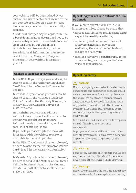
Operating safety
G Warning!
Work improperly carried out on electroniccomponents and associated software couldcause them to cease functioning. Becausethe vehicle’s electronic components areinterconnected, any modifications mademay produce an undesired effect on othersystems. Electronic malfunctions couldseriously impair the operating safety ofyour vehicle.
See an authorized smart center for repairsor modifications to electroniccomponents.
Improper work or modifications on othervehicle systems could also have a negativeimpact on the operating safety of thevehicle.
G Warning!
Some safety systems only function while theengine is running. You should thereforenever turn off the engine while driving.
G Warning!
Heavy blows against the vehicle underbodyor tires/wheels, for example when running
>> Introduction. 15
Z

over an obstacle, road debris or a pothole,may cause serious damage and impair theoperating safety of your vehicle.
If you feel a sudden significant vibrationor ride disturbance, or you suspect thatdamage to your vehicle has occurred, youshould turn on your hazard warningflashers, carefully slow down, and drivewith caution to an area which is a safedistance from the road.
Inspect the vehicle underbody and tires/wheels for possible damage. If the vehicleappears unsafe, have it towed to the nearestauthorized smart center or other qualifiedmaintenance or repair facility for furtherinspection or repairs.
Proper use of the vehicle
Proper use of the vehicle requires that youare familiar with the followinginformation and rules:Rthe safety precautions in this manual
Rthe “Technical data” section in thismanual
Rtraffic rules and regulations
Rmotor vehicle laws and safety standards
G Warning!
Various warning labels are attached to yourvehicle. These warning labels are intendedto make you and others aware of variousrisks. You should not remove any of thesewarning labels unless explicitlyinstructed to do so by information on thelabel itself. Removal of any of these labelsmay cause you and others to be unaware ofcertain risks which may result in anaccident and/or personal injury.
Problems with your vehicle
If you should experience a problem withyour vehicle, particularly one that youbelieve may affect its safe operation, weurge you to immediately contact anauthorized smart center to have theproblem diagnosed and corrected ifrequired. Do not drive the vehicle if youbelieve it may not be safely operated. If thematter is not handled to your satisfaction,please discuss the problem with the smartcenter management, or if necessary contactus at one of the following addresses:
In the USA:smart USA Distributor LLC.Customer Assistance Center1765 Telegraph Rd.Bloomfield Hills, MI 48302
In Canada:Customer Relations DepartmentMercedes-Benz Canada, Inc.98 Vanderhoof AvenueToronto, Ontario, M4G 4C9
Reporting safety defects
For the USA only: The following text ispublished as required of manufacturersunder Title 49, Code of U.S. FederalRegulations, Part 575 pursuant to theNational Traffic and Motor Vehicle SafetyAct of 1966.
Reporting safety defects
If you believe that your vehicle has a defectwhich could cause a crash or could causeinjury or death, you should immediatelyinform the National Highway Traffic SafetyAdministration (NHTSA) in addition tonotifying smart USA Distributor LLC.
If NHTSA receives similar complaints, itmay open an investigation, and if it findsthat a safety defect exists in a group of
16 >> Introduction.

vehicles, it may order a recall and remedycampaign. However, NHTSA cannot becomeinvolved in individual problems betweenyou, your dealer, or smart USA DistributorLLC.
To contact NHTSA, you may call the VehicleSafety Hotline toll-free at 1-888-327-4236(TTY: 1-800-424-9153); go tohttp://www.safercar.gov; or write to:Administrator, NHTSA Headquarters, 1200New Jersey Avenue, SE, West Building,Washington, DC 20590. You can also obtainother information about motor vehiclesafety from http://www.safercar.gov.
Vehicle data recording
Information regarding electronicrecording devices
(Including notice pursuant to CaliforniaCode § 9951)
Please note that your vehicle is equippedwith devices that can record vehiclesystems data.
This information helps, for example, todiagnose vehicle systems after a collisionand to continuously improve vehiclesafety.smart may access the information and shareit with othersRfor safety research or vehicle diagnosis
purposes
Rwith the consent of the vehicle owner orlessee
Rin response to an official request by lawenforcement or other government agency
Rfor use in dispute resolution involvingsmart, its affiliates or sales/serviceorganization and/or
Ras otherwise required or permitted bylaw.
>> Introduction. 17
Z

18

>> A
t a
glan
ce.
Exterior view ................................... 20
Cockpit ........................................... 21
Overhead control panel ...................... 23
Door control panel ............................ 23
Instrument cluster (miles) .................. 24
Instrument cluster (kilometers) ........... 26
Steering wheel gearshift control .......... 28
Upper center console ......................... 28
Lower center console ......................... 29

Exterior view
20 Exterior view>>
At
a gl
ance
.

Function Page
: Soft top system1 73
; Cargo compartment:
Locking and unlocking 55
Opening and closing(cabriolet) 58
Opening and closing(coupé) 57
Opening enginecompartment cover 111
Engine oil 112
Rear window defroster 100
= Rear lamps 170
? Fuel filler flap 110
A Doors:
Locking and unlocking 55
Locking and unlockingmanually 166
B Exterior rear viewmirrors 63
Function Page
C Tires and wheels 118,206
Checking tire inflationpressure 119
Flat tire 176
D Towing 189
Installing towing eye bolt 190
E Front lamps 169
F Opening service flap 114
Coolant 115
Windshield washer fluid 116
G Windshield wipers 71
Replacing wiper blades 174
H Windshield:
Defrosting 99
Wiping with windshieldwasher fluid 72
1 cabriolet only.
Exterior view 21
>> A
t a
glan
ce.

Cockpit
Function Page
: Exterior lamp switch:
Low beam 67
Turn signals 68
High beam 68
; Steering wheel2
= Instrument cluster:
Miles 24
Kilometers 26
? Wiper switch:
Windshield wipers 71
Rear window wiper3 72
A Tachometer* 93
B Cockpit clock* 93
C Overhead control panel 23
D Upper center console 28
E Glove box 104
Function Page
F smart MP3 interface*(AUX-socket*) 95
G Gear selector lever 83
H Starter switch 59
I Coin holder 103
Retractable soft topswitch4 74
J Cup holder 101
K Horn
L On-board DiagnosticsSocket (OBD) 201
M Door control panel 78,63
N Inside door handle 56
2 Model pure only: The steering wheel in this vehicle varies from steering wheel illustrated.3 coupé only.4 cabriolet only.
22 Cockpit>>
At
a gl
ance
.
* optional

Overhead control panel
Function Page
: Passenger front air bagoff indicator lamp 42
; Switching interiorlighting on/off 70
= Interior rear view mirror 64
Door control panel
Function Page
: Inside door handle 56
; Adjusting exterior rearview mirrors:
Manually 63
Electrically5 63
= Opening and closing rightside window:
Manually 78
Electrically5 78
? Opening and closing leftside window:
Manually 78
Electrically5 78
5 Model passion only.
Door control panel 23
>> A
t a
glan
ce.

Instrument cluster (miles)
Instrument cluster (U.S. vehicles)
24 Instrument cluster (miles)>>
At
a gl
ance
.

Function Page
: Selecting display forstatus indicator 91
Setting digital clock 90
; Left indicator lampdisplay with:
M Low‑beamheadlamp indicatorlamp
67,159
K High‑beamheadlamp indicatorlamp
68,159
h Combination lowtire pressure/TPMSmalfunctiontelltale 162
7 Seat belt telltale 155
6 SRS indicator lamp 155
= # Left turn signalindicator lamp
68,159
? d ESP® warning lamp 157
A ! Right turn signalindicator lamp
68,159
B Speedometer
C Right indicator lampdisplay with:D EPS* warning lamp 157
; Engine malfunctionindicator lamp 160
¬ ABS indicator lamp 153
$ Brake warning lamp 154
Function Page
D Adjusting instrumentcluster illumination 93
Setting digital clock 90
E Right center indicatorlamp display with:
5 Engine oil pressureindicator lamp 161
? Coolanttemperaturewarning lamp 160
F Multifunction displaywith:
Fuel level display 91
Transmission positionindicator 89
Main odometer display 89
Digital clock 90
Outside temperaturedisplay 90
G Status indicator with:
Trip odometer display 92
Maintenance serviceinterval display 92
Reserve fuel indicator 92
H Left center indicatorlamp display with:
# Battery indicatorlamp 158
® Fuel cap indicatorlamp 160
Instrument cluster (miles) 25
>> A
t a
glan
ce.
* optional

Instrument cluster (kilometers)
Instrument cluster (Canada vehicles)
26 Instrument cluster (kilometers)>>
At
a gl
ance
.

Function Page
: Selecting display forstatus indicator 91
Setting digital clock 90
; Left indicator lampdisplay with:
M Low‑beamheadlamp indicatorlamp
67,159
K High‑beamheadlamp indicatorlamp
68,159
h Combination lowtire pressure/TPMSmalfunctiontelltale 162
7 Seat belt telltale 155
6 SRS indicator lamp 155
= # Left turn signalindicator lamp
68,159
? d ESP® warning lamp 157
A ! Right turn signalindicator lamp
68,159
B Speedometer
C Right indicator lampdisplay with:D EPS* warning lamp 157
; Engine malfunctionindicator lamp 160
! ABS indicator lamp 153
J Brake warning lamp 154
D Adjusting instrumentcluster illumination 93
Setting digital clock 90
Function Page
E Right center indicatorlamp display with:
5 Engine oil pressureindicator lamp 161
? Coolanttemperaturewarning lamp 160
F Multifunction displaywith:
Fuel level display 91
Transmission positionindicator 89
Main odometer display 89
Digital clock 90
Outside temperaturedisplay 90
Freeze warning 91
G Status indicator with:
Trip odometer display 92
Maintenance serviceinterval display 92
Reserve fuel indicator 92
H Left center indicatorlamp display with:
# Battery indicatorlamp 158
® Fuel cap indicatorlamp 160
Instrument cluster (kilometers) 27
>> A
t a
glan
ce.
* optional

Steering wheel gearshift control
Function Page
: Left shift paddle6:Downshift 86
; Multifunction display 88
= Right shift paddle6:Upshift 86
i Model pure only:
The steering wheel in this vehicle variesfrom steering wheel illustrated.
Upper center console
Function Page
: Tachometer* 93
; Cockpit clock* 93
= HVAC 95
? Audio system* 94
A Hazard warning flasherswitch 70
B Switching tow-awayprotection*/interiormotion sensor* on/off 50
C Switching seat heating*on/off, passenger side 62
D Restarting TPMS button 121
E Central unlocking switch 55
F Central locking switch 55
6 Model passion only.
28 Upper center console>>
At
a gl
ance
.
* optional

Function Page
G Switching front foglamps* on/off 69
H Switching seat heating*on/off, driver’s side 62
Lower center console
Function Page
: Auxiliary power outlet 107
; Gear selector lever 83
= Starter switch 59
? Parking brake lever 81
A Coin holder 103
Retractable soft topswitch7 74
7 cabriolet only.
Lower center console 29
>> A
t a
glan
ce.
* optional Z

30

>> S
afet
y.
Occupant safety ................................ 32
Panic alarm ..................................... 46
Driving safety systems ....................... 47
Anti-theft systems ............................ 49

Occupant safety
Introduction
The smart vehicle is equipped with seatbelts and dual stage air bags to protect youin a crash. However, children can be killedor seriously injured by an inflating airbag. Indeed, there is a stronger risk ofserious death or bodily injury when an airbag deploys on a child positioned in arear-facing child seat in the passengerseat. Because this vehicle has only twofront seats and no backseat, it is limitedas are other two-seat vehicles, in theextent to which it may restrain childrentraveling in the passenger front seat. Manystates have laws against placing childrenof certain ages in the front seat of avehicle that has both front and back seats.Those laws make exceptions to permitchildren to be restrained in the front seatof two seat vehicles. Special instructionsand warnings are provided below aboutwhen and if you may restrain a child in thepassenger seat of the smart vehicle. Undercertain circumstances, it is appropriatefor the passenger air bag not to operatewhen a child is restrained in a car seat inthe passenger seat, and this vehicle isequipped with technology to accomplishthis. Please pay very close attention to theinstructions and warnings below,particularly as they relate to children.
In this section you will learn the mostimportant facts about the restraint systemcomponents of the vehicle.
The restraint systems are
RSeat belts (Y page 33)
RChild restraints (Y page 43)
Additional protection potential isprovided by:
RSupplemental Restraint System (SRS)with
- Air bags (Y page 35)
- Air bag control unit (with crashsensors)
- Emergency Tensioning Devices andseat belt force limiters (Y page 35)
RAir bag system components with- Passenger front air bag off indicator
lamp (Y page 42)
- Passenger seat with OccupantClassification System (OCS)(Y page 39)
Although independent systems, theirprotective functions work in conjunctionwith each other.
i For information on infants andchildren traveling with you in thevehicle and restraint systems for infantsand children, see “Children in thevehicle” (Y page 43).
The SRS system conducts a self-test whenthe ignition is switched on and in regularintervals while the engine is running. Thisfacilitates detection of malfunctions. TheSRS indicator lamp 6 in the instrumentcluster comes on when the ignition isswitched on and goes out afterapproximately four seconds.
The SRS components are in operationalreadiness if the SRS indicator lamp 6is not lit when the engine is running.
A malfunction in the system has beendetected if the SRS indicator lamp 6:Rfails to go out after approximately 4
seconds after the ignition was switchedon
Rdoes not come on at all
Rcomes on after the engine was started orwhile driving
G Warning!
Modifications to or work improperlyconducted on restraint systems (such as
32 Occupant safety>>
Saf
ety.

seat belts and anchors, EmergencyTensioning Devices, seat belt forcelimiters or air bags) or their wiring, aswell as tampering with interconnectedelectronic systems, can lead to therestraint systems no longer functioning asintended. Air bags or EmergencyTensioning Devices, for example, coulddeploy inadvertently or fail to deploy inaccidents in which they otherwise shoulddeploy (although the decelerationthreshold for air bag deployment isexceeded). Therefore, never modify therestraint systems. Do not tamper withelectronic components or their software.
G Warning!
In the event that the SRS indicator lamp6 comes on while driving or does notcome on at all, the SRS self-check hasdetected a malfunction. For your safety, westrongly recommend that you immediatelybut safely pull the vehicle off of theroadway and stop driving. Contact anauthorized smart center immediately tohave the system checked; otherwise the SRSmay not deploy when needed in an accident,which could result in serious or fatalinjury, or it might deploy unexpectedly andunnecessarily which could also result ininjury.
In addition, improper repair work on theSRS creates a risk of rendering the SRSinoperative or causing unintended air bagdeployment. Work on the SRS must thereforeonly be performed by qualifiedtechnicians. Contact an authorized smartcenter. If it is necessary to modify an airbag system to accommodate a person withdisabilities, contact your local authorizedsmart center.
Seat belts
The use of seat belts and infant and childrestraint systems is required by law in all50 states, the District of Columbia, the U.S.territories and all Canadian provinces.
Even where this is not the case, all vehicleoccupants should have their seat beltsfastened whenever the vehicle is beingoperated.
For more information, see “Fastening theseat belts” (Y page 64).
i For information on infants andchildren traveling with you in thevehicle and restraint systems for infantsand children, see “Children in thevehicle” (Y page 43).
G Warning!
Always fasten your seat belt before driving.Always make sure all of your passengers areproperly restrained.
Failure to wear and properly fasten andposition your seat belt greatly increasesyour risk of injuries and their likelyseverity in an accident. You and yourpassenger should always wear seat belts.
If you are ever in an accident, your injuriescan be considerably more severe withoutyour seat belt properly buckled.
Without your seat belt buckled, you aremuch more likely to hit the interior of thevehicle or be ejected from it. You can beseriously injured or killed.
In the same crash, the possibility of injuryor death is lessened if you are properlywearing your seat belt. Air bags can onlyprotect you if you are properly wearingyour seat belt.
G Warning!
Never ride in a moving vehicle with the seatbackrest in an excessively reclinedposition as this can be dangerous. Youcould slide under the seat belt in acollision. If you slide under it, the belt
Occupant safety 33
>> S
afet
y.
Z

would apply force at the abdomen or neck,causing serious or even fatal injuries. Theseat backrest and seat belt provide the bestrestraint when the wearer is in a positionthat is as upright as possible and the beltis properly positioned on the body.
G Warning!
Never let more people ride in the vehiclethan there are seat belts available. Makesure everyone riding in the vehicle iscorrectly restrained with a separate seatbelt. Never use a seat belt for more than oneperson at a time.
G Warning!
Seat belts of a vehicle involved in anaccident must be inspected by smart. Onlythen is it possible to determine whetherthe seat belts were damaged or stressed inthe accident. Damaged or stressed seatbelts may not properly protect you in asubsequent accident.
Only use seat belts which have beenapproved by smart.
Do not make any modifications to the seatbelts. This can lead to unintendedactivation of the Emergency TensioningDevices (ETDs) or to their failure toactivate when necessary.
Do not bleach or dye seat belts as this mayseverely weaken them. In a crash, they maynot be able to provide adequate protection.
Have all work carried out only by qualifiedtechnicians. Contact an authorized smartcenter.
G Warning!
USE SEAT BELTS PROPERLY
RSeat belts can only work when usedproperly. Never wear seat belts in anyother way than as described in thissection, as that could result in seriousinjuries in case of an accident.
REach occupant should wear their seat beltat all times, because seat belts help
reduce the likelihood of and potentialseverity of injuries in accidents,including rollovers. The integratedrestraint system includes SRS (driverfront air bag, passenger front air bag,head-thorax air bags) and EmergencyTensioning Devices (ETDs) with seat beltforce limiters.
The system is designed to enhance theprotection provided by secured seatbelts in certain frontal and sideimpacts.
RNever wear the shoulder belt under yourarm, against your neck or off yourshoulder. Doing so may cause your body tomove too far forward in a frontal crash,which would increase the chance of headand neck injuries. The seat belt wouldalso apply too much force to the ribs orabdomen, which could severely injureinternal organs such as your liver orspleen.
RNever wear seat belts over rigid orbreakable objects in or on your clothing,such as eyeglasses, pens, keys, etc., asthese might cause injuries.
RPosition the lap belt as low as possibleon your hips and not across the abdomen.If the lap seat belt is positioned acrossyour abdomen, it could cause seriousinjuries in a crash.
RNever use a seat belt for more than oneperson at time. Do not fasten a single seatbelt around a person and another personor other objects.
RSeat belts should not be worn twisted. Ina crash, you would not have the full widthof the seat belt to manage impact forces.The twisted seat belt against your bodycould cause injuries.
RPregnant women should also always use alap-shoulder belt. The lap belt portionshould be positioned as low as possibleon the hips to avoid any possiblepressure on the abdomen.
34 Occupant safety>>
Saf
ety.

RNever place your feet on the instrumentpanel, dashboard or on the seat. Alwayskeep both feet on the floor in front of theseat.
RWhen using a seat belt to secure infant ortoddler restraints or children in boosterseats, always follow the child seatmanufacturer’s instructions.
Emergency Tensioning Devices (ETDs)and seat belt force limiters
The seat belts are equipped withEmergency Tensioning Devices and seatbelt force limiters.
Emergency Tensioning Devices aredesigned to activate in the followingcases:Rin frontal or rear-end impacts
exceeding the system deploymentthreshold
Rif the restraint systems are operationaland functioning correctly
Rin collisions with high vehicledeceleration/acceleration in thelongitudinal direction, e.g. a head-oncollision
Ron passenger side when the seat isoccupied and the seat belt is fastened
Rindependently of the front air bags
When activated, Emergency TensioningDevices remove slack from the seat belts insuch a way that the seat belts fit moresnugly against the body. Seat belt forcelimiters, when activated, reduce the forceexerted by the seat belts on occupantsduring a crash.
When the emergency tensioning device istriggered, the SRS indicator lamp 6 inthe instrument cluster illuminates, see“SRS indicator lamp” (Y page 155).
G Warning!
Once they have been triggered, EmergencyTensioning Devices will no longer functionproperly and must be replaced. smartrecommends that you visit a qualifiedworkshop to have this done. In particular,work relevant to safety or on safety-relatedsystems must be carried out at a qualifiedspecialist workshop.
Comply with safety regulations whendisposing of Emergency TensioningDevices. These regulations are available atany smart center.
The belt force limiter is designed tooperate in unison with the front air bag,which absorbs a portion of the seat belt’sdecelerating forces, distributing the loadover a larger area.
In the event of a head-on or rear-endcollision, the emergency tensioningdevice is activated if the vehicle isdecelerated or accelerated sufficiently inthe longitudinal direction at the start ofimpact with the ignition switched on.
Air bags
Air bags can reduce the severity ofinjuries in serious collisions, e.g. in ahead-on collision or a side impact.
G Warning!
Air bags are designed to reduce thepotential of injury in certain frontalimpacts (front air bags), or side impacts(head-thorax air bags) which may causesignificant injuries. However, no systemavailable today can completely eliminateinjuries and fatalities.
The deployment of the air bags temporarilyreleases a small amount of dust from the airbags. This dust is neither injurious to yourhealth, nor does it indicate a fire in thevehicle. The dust might cause sometemporary breathing difficulty for people
Occupant safety 35
>> S
afet
y.
Z

with asthma or other breathing trouble. Toavoid this, you may wish to get out of thevehicle as soon as it is safe to do so. If youhave any breathing difficulty but cannotget out of the vehicle after the air baginflates, then get fresh air by opening awindow or door.
G Warning!
To reduce the risk of injury when the frontair bags inflate, it is very important forthe driver and passenger to always be in aproperly seated position and to wear theirrespective seat belt.
For maximum protection in the event of acollision always be in normal seatedposition with your back against thebackrest. Fasten your seat belt and ensureit is properly positioned on your body.
Since the air bag inflates withconsiderable speed and force, a properseating and hands on steering wheelposition will help to keep you at a safedistance from the air bag.
Occupants who are unbelted, out of positionor too close to the air bag can be seriouslyinjured or killed by an air bag as itinflates extremely quickly and with greatforce:
RSit properly belted in a position that isas upright as possible with your backagainst the seat backrest.
RAdjust the driver’s seat as far as possiblerearward, still permitting properoperation of vehicle controls. Thedistance from the center of the driver’sbreastbone to the center of the air bagcover on the steering wheel must be atleast 10 inches (25 cm) or more. You shouldbe able to accomplish this byadjustments to the seat. If you have anyproblems, please contact an authorizedsmart center.
RDo not lean your head or chest close to thesteering wheel or dashboard.
RKeep hands on the outside of the steeringwheel rim. Placing hands and arms insidethe rim can increase the risk andpotential severity of hand/arm injurywhen the driver’s front air bag inflates.
RAdjust the passenger seat as far aspossible rearward from the dashboardwhen the seat is occupied.
ROccupants, especially children, shouldalways sit as upright as possible,properly use the seat belts and use anappropriately sized infant restraint,toddler restraint, or booster seatrecommended for the size and weight ofthe child.
Failure to follow these instructions canresult in severe injuries to you or otheroccupants.
If you sell your vehicle, it is important thatyou make the buyer aware of this safetyinformation. Be sure to give the buyer thisOperator’s Manual.
i Air bags are designed to deploy only incertain frontal impacts (front air bags),and in side impacts (head-thorax airbags) which exceed preset thresholds.Only during these events will theyprovide their supplemental protection.
The driver and passenger should alwayswear their seat belts. Otherwise it is notpossible for air bags to provide theirsupplemental protection.
In case of other types of impacts andimpacts below air bag deploymentthresholds, air bags will not deploy. Thedriver and passenger will then beprotected to the extent possible by aproperly fastened seat belt. A properlyfastened seat belt is also needed toprovide the best possible protection ina rollover.
36 Occupant safety>>
Saf
ety.

We caution you not to rely on the presenceof the air bags in order to avoid wearingyour seat belt.
It is important to your safety and that ofyour passenger that you replace deployedair bags and repair any malfunctioningair bags to make sure the vehicle willcontinue to provide supplemental crashprotection for occupants.
Safety guidelines for the seat belt,Emergency Tensioning Devices (ETDs)and air bag
G Warning!
RDamaged seat belts or seat belts that werehighly stressed in an accident must bereplaced and their anchoring pointsmust also be checked. Only use seat beltsinstalled or supplied by an authorizedsmart center.
RAir bags and Emergency TensioningDevices (ETDs) contain Perchloratematerial, which may require specialhandling and regard for the environment.Check with your local government’sdisposal guidelines. Californiaresidents, see http://www.dtsc.ca.gov/HazardousWaste/Perchlorate/index.cfm.
RGiven the considerable deploymentspeed, required inflation volume, andthe textile structure of the air bags,there is the possibility of abrasions orother, potentially more serious injuriesresulting from air bag deployment.
RAir bags and Emergency TensioningDevices (ETDs) are designed to functionon a one-time-only basis. An air bag orETD that has deployed must be replaced.
RDo not pass seat belts over sharp edges.They could tear.
RDo not make any modification that couldchange the effectiveness of the seatbelts.
RNo modifications of any kind may be madeto any components or wiring of the SRS.This includes changing or removing anycomponent or part of the SRS, theinstallation of additional trimmaterial, badges, etc. over the steeringwheel hub, passenger front air bag cover,outboard sides of the seat backrests, andinstallation of additional electrical/electronic equipment on or near SRScomponents and wiring. Keep areabetween air bags and occupants free fromobjects (e.g. packages, purses,umbrellas, etc.).
RDo not bleach or dye seat belts as this mayseverely weaken them. In a crash they maynot be able to provide adequateprotection.
RDo not hang hangers on the coat hooks orhandles over the door. These items mayturn into projectiles and cause head andother injuries when the head-thorax airbag is deployed.
RAir bag system components will be hotafter an air bag has inflated. Do nottouch.
RNever place your feet on the instrumentpanel, dashboard, or on the seat. Alwayskeep both feet on the floor in front of theseat.
RIn addition, improper repair work on theSRS creates a risk of rendering the SRSinoperative or causing unintended airbag deployment. Work on the SRS musttherefore only be performed by qualifiedtechnicians. Contact an authorized smartcenter.
RFor your protection and the protection ofothers, when scrapping the air bag unitor Emergency Tensioning Devices (ETDs),our safety instructions must be followed.These instructions are available fromany authorized smart center.
Occupant safety 37
>> S
afet
y.
Z

How the air bag operates
The air bag is inflated in a matter ofmilliseconds. If the air bag is triggered,the SRS indicator lamp in the instrumentcluster illuminates.
! If the air bags are activated, you willhear a loud noise and some dust may begenerated. The explosion fundamentallyrepresents no risk to your hearing.
The inflated air bag slows down andreduces the movement of the occupant. Whenthe occupant makes contact with the airbag, hot gas flows out of the inflated frontair bags and head-thorax air bags. Thisreduces the load on the occupant’s head andupper body. These air bags areconsequently deflated after the accident.
Head-thorax air bags
G Warning!
There is a possibility for a head-thorax airbag related injury if occupants, especiallychildren, are not properly seated orrestrained when next to a head-thorax airbag which needs to deploy rapidly in a sideimpact in order to do its job.
To help avoid the possibility of injury,please follow these guidelines:
(1) Occupants, especially children,should never place their bodiesor lean their heads in the area ofthe door where the head-thoraxair bag inflates. This couldresult in serious injuries ordeath should the head-thorax airbag be deployed.
(2) Always sit as upright aspossible, properly use the seatbelts, and for all children12 years old or under, use anappropriately sized infantrestraint, toddler restraint, or
booster seat recommended forthe size and weight of the child.
(3) Always wear seat belts properly.
G Warning!
Only use seat covers which have been testedand approved by smart for your vehiclemodel. Using other seat covers mayinterfere with or prevent the deployment ofthe head-thorax air bags. Contact anauthorized smart center for availability.
If activated, the head-thorax air bags areintended to increase the potentialprotection for the head and thorax (but notarms) of the occupants on the side of thevehicle that is struck.
The head-thorax air bags are deployed
Ron the side of the vehicle that is struck(when passenger side is struck only if theseat is occupied)
Rat the start of an accident with highvehicle deceleration or accelerationacting in a lateral direction, e.g. a sideimpact
Rregardless of whether or not the seat beltis in use
Rindependently of the front air bagsbeing deployed
Rindependently of the emergencytensioning device
38 Occupant safety>>
Saf
ety.

The head-thorax air bags are integratedinto the driver and passenger seatbackrests.
: Head-thorax air bag
Driver front air bag/passenger front airbag
The front air bags are designed to reducethe potential of injury in certain frontalimpacts.
Driver front air bag and passenger frontair bag are deployed
Rat the start of an accident with highvehicle deceleration in the longitudinaldirection
Rindependently of other air bags in thevehicle being deployed
Rnever in the event of a rollover, unlesshigh vehicle deceleration in thelongitudinal direction is detected
i The front air bags in this vehicle havebeen designed to inflate in two stages.This allows the air bag to have differentrates of inflation that are based on therate of relevant vehicle decelerationand a fastened or unfastened seat belt asassessed by the air bag control unit.
On the passenger side, the front air bagdeployment is additionally influencedby the passenger’s weight category asidentified by the OccupantClassification System (OCS)(Y page 39).
The lighter the passenger side occupant,the higher the vehicle deceleration raterequired for the second stage inflationof the air bag.
The air bags will not deploy in impactswhich do not exceed the system’sdeployment thresholds. In such instances,the seat belts are designed to protect you.
The passenger air bag will only bedeployed if
Rthe system, based on OCS weight sensorreadings, senses that the passenger seatis occupied and the 40indicator lamp is not lit (Y page 42)
Rthe impact exceeds a preset deploymentthreshold
The driver front air bag is located in thesteering wheel housing, the passengerfront air bag above the glove box.
: Driver front air bag
; Passenger front air bag
Occupant Classification System
The Occupant Classification System (OCS)automatically turns the passenger front airbag on or off based on the classifiedoccupant weight category determined byweight sensor readings from the passengerseat.
i The system does also deactivate thehead-thorax air bag, the seat EmergencyTensioning Devices, and the seat belt
Occupant safety 39
>> S
afet
y.
Z

force limiters, based on the classifiedoccupant weight category determined byweight sensor readings from thepassenger seat.
Occupants must sit properly belted in aposition that is as upright as possible withtheir back against the seat backrest andfeet on the floor to be correctly classified.If the occupant’s weight is transferred toanother object in the vehicle (e.g. byleaning on armrests), the OCS may not beable to properly approximate theoccupant’s weight category.
i If the seat, including the trim cover andcushion, needs to be serviced in any way,take the vehicle to an authorized smartcenter. Only seat accessories approvedby smart may be used.
Both driver and the passenger shouldalways use the 40 indicatorlamp as an indication of whether or notthe passenger is properly positioned(Y page 42).
G Warning!
If the 40 indicator lampilluminates when an adult or someonelarger than a small individual is in thepassenger seat, have the passenger re-position himself or herself in the seatuntil the 40 indicator lampgoes out.
In the event of a collision, the air bagcontrol unit will not allow passenger frontair bag deployment when the OCS classifiedthe passenger seat occupant as being up toor less than the weight of a typical12‑month‑old child in a standard childrestraint or if the passenger seat is sensedas being empty.
When the OCS senses that the passenger seatoccupant is classified as being up to orless than the weight of a typical12‑month‑old child in a standard childrestraint, the 40 indicator
lamp will illuminate when the ignition isswitched on and remain illuminated,indicating that the passenger front air bagis deactivated.
When the OCS senses that the passenger seatis classified as being empty, the40 indicator lamp willilluminate and remains illuminated.
When the OCS senses that the passenger seatoccupant is classified as being heavierthan the weight of a typical 12‑month‑oldchild seated in a standard child restraintor as being a small individual (such as ayoung teenager or a small adult), the40 indicator lamp willilluminate for approximately 4 secondswhen the ignition is switched on and then,depending on occupant weight sensorreadings from the seat, remainsilluminated or goes out.
When the 40 indicator lamp isilluminated, the passenger front air bag isdeactivated.
When the 40 indicator lamp isout and the passenger seat is occupied byan adult or someone larger than a smallindividual, the passenger front air bag isactivated.
When the OCS senses that the passenger seatoccupant is classified as an adult orsomeone larger than a small individual, the40 indicator lamp willilluminate for approximately 4 secondswhen the ignition is switched on and thengoes out, indicating that the passengerfront air bag is activated.
If the 40 indicator lamp isilluminated, the passenger front air bag isdeactivated and will not be deployed.
40 Occupant safety>>
Saf
ety.

If the 40 indicator lamp is notilluminated, the passenger front air bag isactivated and will be deployed:
Rin the event of certain frontal impacts
Rif impact exceeds a preset deploymentthreshold
Rindependently of the head-thorax airbags
If the passenger front air bag is deployed,the rate of inflation will be influenced by:
Rthe rate of vehicle deceleration and afastened or unfastend seat belt asassessed by the air bag control unit
Rthe passenger’s weight category asidentified by the OccupantClassification System (OCS).
G Warning!
Children 12 years old and under must beseated and properly secured in anappropriate infant or child restraintrecommended for the size and weight of thechild.
The infant or child restraint must beproperly secured with the vehicle’s seatbelt, fully in accordance with the childseat manufacturer’s instructions.
Children can be killed or seriously injuredby an inflating air bag. Note the followingimportant information:
RYour vehicle is equipped with air bagtechnology designed to turn off thepassenger front air bag in your vehiclewhen the system senses the weight of atypical 12‑month‑old child or less alongwith the weight of a standardappropriate child restraint on thepassenger seat.
RA child in a rear-facing child restrainton the passenger seat will be seriouslyinjured or even killed if the passengerfront air bag inflates in a collisionwhich could occur under some
circumstances, even with the air bagtechnology installed in your vehicle.
RIf you install a rear-facing childrestraint on the passenger seat, makesure the 40 indicator lampis illuminated, indicating that thepassenger front air bag is deactivated.Should the 40 indicatorlamp not illuminate or go out while therestraint is installed, please checkinstallation.
Periodically check the 40indicator lamp while driving to makesure the 40 indicator lampis illuminated.
If the 40 indicator lampgoes out or remains out, do not transporta child on the passenger seat until thesystem has been repaired.
A child in a rear-facing child restrainton the passenger seat may be seriouslyinjured or even killed if the passengerfront air bag inflates.
RIf you place a child in a forward-facingchild restraint on the passenger seat,move the seat as far back as possible, usethe proper child restraint recommendedfor the age, size and weight of the childby the seat manufacturer, and securechild restraint with the vehicle’s seatbelt according to the child seatmanufacturer’s instructions. Forchildren larger than the typical12‑month‑old child, the passenger frontair bag may or may not be activated.
i Deployment of the driver front air bagdoes not mean that the passenger frontair bag also should have deployed.
The Occupant Classification System(Y page 39) may have determined:Rthat the seat was empty or occupied by the
weight up to or less than that of a typical12‑month‑old child seated in a standard
Occupant safety 41
>> S
afet
y.
Z

child restraint — both instances wherethe system suppresses deployment of thepassenger front air bag even though theimpact met the criteria and was ofsufficient severity to deploy the driverfront air bag.
Rthat the seat was occupied by a smallindividual (such as a young teenager ora small adult) or a child weighing morethan the weight of a typical 12‑month‑oldchild in a standard child restraint —instances where the system may suppressdeployment of the passenger front airbag even though the impact met thecriteria and was of sufficient severityto deploy the driver front air bag.
Passenger front air bag off indicatorlamp
The indicator lamp is located on theoverhead control panel.
Passenger front air bag off indicatorlamp : illuminates when the passengerfront air bag is deactivated.
G Warning!
When the SRS indicator lamp 6 and the40 indicator lamp are lit atthe same time, there is a malfunction in theOccupant Classification System.
In order to ensure proper operation of theair bag system and OCS:
RHave the system checked as soon aspossible by qualified technicians.Contact an authorized smart center.
RSit properly belted in a position that isas upright as possible with your backagainst the seat backrest.
RDo not lean on the armrests or liftyourself from the seat by using the handleover the door as this may cause the OCS tobe unable to correctly approximate theoccupant weight category.
ROnly have the seat repaired or replacedby an authorized smart center.
RRead and observe all warnings in thischapter.
Self-test Occupant ClassificationSystem
After turning the key in the starter switchto position 1 or 2, the 40indicator lamp located in the centerconsole illuminates. If an adult occupantis properly sitting on the passenger seatand the system senses the occupant as beingan adult, the 40 indicatorlamp will illuminate and go out afterapproximately 4 seconds.
If the seat is not occupied and the systemsenses the passenger seat as being empty,the 40 indicator lamp willilluminate and remains illuminated.
G Warning!
If the 40 indicator lampshould not illuminate immediately afterstarting the engine, the system is notfunctioning. You must contact anauthorized smart center before seating anychild on the passenger seat.
More information can be found in the“Practical hints” section (Y page 163).
42 Occupant safety>>
Saf
ety.

G Warning!
Never place anything between seat cushionand child seat (e.g. pillow), since itreduces the effectiveness of the OccupantClassification System. The bottom of thechild seat must make full contact with thepassenger seat cushion. An incorrectlymounted child seat could cause injuries tothe child in case of an accident, instead ofincreasing protection for the child.
Follow the manufacturer’s instructions forinstallation of child seats.
Children in the vehicle
If an infant or child is traveling with youin the vehicle:
X Secure the child using an infant or childrestraint appropriate to the age and sizeof the child.
X Make sure the infant or child is properlysecured at all times while the vehicle isin motion.
G Warning!
Do not leave children unattended in thevehicle, even if they are secured in a childrestraint system. The children could
Rinjure themselves on parts of the vehicle
Rbe seriously or fatally injured throughexcessive exposure to extreme heat orcold
Do not expose the child restraint system todirect sunlight. The child restraintsystem’s metal parts, for example, couldbecome very hot, and the child could beburned on these parts.
If children open a door, they could
Rinjure other persons
Rget out of the vehicle and injurethemselves or be injured by followingtraffic
Do not carry heavy or hard objects in thepassenger compartment unless they arefirmly secured in place.
For more information, please refer to the“Loading and storing section”.
Unsecured or improperly positioned cargoincreases a child’s risk of injury in theevent of
Rstrong braking maneuvers
Rsudden changes of direction
Ran accident
Infant and child restraint system
We recommend all infants and children beproperly restrained at all times while thevehicle is in operation.
The passenger lap-shoulder belt has aspecial seat belt retractor for securefastening of child restraints.
To fasten a child restraint, follow allmounting instructions provided by thechild restraint manufacturer. Then pull theshoulder seat belt out completely and let itretract. During seat belt retraction, aratcheting sound can be heard to indicatethat the special seat belt retractor isactivated. The seat belt is now locked. Pushdown on child restraint to take up anyslack.
To deactivate, release seat belt buckle andlet seat belt retract completely. Todeactivate the special seat belt retractorfor the passenger seat, the passenger seatmust be in the most backward position. Theseat belt can again be used in the usualmanner.
G Warning!
Never release the seat belt buckle while thevehicle is in motion, since the special seatbelt retractor will be deactivated.
The use of infant or child restraints isrequired by law in all 50 states, the
Occupant safety 43
>> S
afet
y.
Z

District of Columbia, the U.S. territories,and all Canadian provinces.
Infants and small children should be seatedin an appropriate infant or child restraintsystem properly secured in accordancewith the manufacturer’s instructions forthe child restraint, that complies with U.S.Federal Motor Vehicle Safety Standards 213and 225 and Canadian Motor Vehicle SafetyStandards 213, 213.1 and 213.2.
A statement by the child restraintmanufacturer of compliance with thesestandards can be found on the instructionlabel on the restraint and in theinstruction manual provided with therestraint.
When using any infant restraint, toddlerrestraint, or booster seat be sure tocarefully read and follow allmanufacturer’s instructions forinstallation and use.
Please read and observe warning labelsaffixed to the inside of the vehicle and toinfant or child restraints.
G Warning!
Children 12 years old and under must beseated and properly secured in anappropriately sized infant restraint,toddler restraint, or booster seatrecommended for the size and weight of thechild.
The infant or child restraint must beproperly secured with the vehicle’s seatbelt fully in accordance with the child seatmanufacturer’s instructions.
Occupants, especially children, shouldnever place their bodies or lean theirheads in the area of the door where thehead-thorax air bag inflates. This couldresult in serious injuries or death shouldthe head-thorax air bag be triggered.Always sit as upright as possible, properlyuse the seat belt and use an appropriatelysized infant restraint, toddler restraint,
or booster seat recommended for the sizeand weight of the child.
Children can be killed or seriously injuredby an inflating air bag. Note the followingimportant information when circumstancesrequire you to place a child in thepassenger seat:
RYour vehicle is equipped with air bagtechnology designed to turn off thepassenger front air bag in your vehiclewhen the Occupant Classification Systemsenses the weight of a typical12‑month‑old child or less along with theweight of an appropriate child restrainton the passenger seat.
RA child in a rear-facing child restrainton the passenger seat may be seriouslyinjured or even killed if the passengerfront air bag inflates in a collision.
RIf you install a rear-facing childrestraint on the passenger seat, makesure the 40 indicator lampis illuminated, indicating that thepassenger front air bag is deactivated.
Should the 40 indicatorlamp not illuminate or go out while therestraint is installed, please checkinstallation. Periodically check the40 indicator lamp whiledriving to make sure the 40indicator lamp is illuminated. If the40 indicator lamp goes outor remains out, do not transport a childon the passenger seat until the system hasbeen repaired. A child in a rear-facingchild restraint on the passenger seat maybe seriously injured or even killed if thepassenger front air bag inflates.
RIf you place a child in a forward-facingchild restraint on the passenger seat,move the seat as far back as possible, usea proper child restraint recommendedfor the age, size and weight of the child,and secure child restraint with thevehicle’s seat belt according to the child
44 Occupant safety>>
Saf
ety.

seat manufacturer’s instructions. Forchildren larger than the typical12‑month‑old child, the passenger frontair bag may or may not be activated.
G Warning!
Infants and small children should nevershare a seat belt with another occupant.During an accident, they could be crushedbetween the occupant and seat belt.
A child’s risk of serious or fatal injuriesis significantly increased if the childrestraint are not properly secured in thevehicle and/or the child is not properlysecured in the child restraint.
Children too big for a toddler restraintmust ride in a seat using regular seat belt.
Position shoulder belt across chest andshoulder, not face or neck. A booster seatmay be necessary to achieve proper seatbelt positioning for children over 41 lbsuntil they reach a height where a lap-shoulder belt fits properly without abooster.
When the child restraint is not in use,remove it from the vehicle or secure it withthe seat belt to prevent the child restraintfrom becoming a projectile in the event ofan accident.
Do not leave children unattended in thevehicle, even if the children are secured ina child restraint system. Unsupervisedchildren in a child restraint system mayuse vehicle equipment and may cause anaccident and/or serious personal injury.
If you are using a rear-facing childrestraint system on the passenger seat, youmust verify that the passenger front air bagis deactivated. When the passenger frontair bag is deactivated, the40 indicator lamp isilluminated (Y page 42).
Top tether
Top tether permits an additionalconnection between a child restraintsystem and the passenger seat. Properusage of the top tether, in accordance withinstructions provided by the childrestraint manufacturer, can further reducethe risk of injuries.
The top tether anchorage is located on thefloor of the cargo compartment. The toptether guide for the top tether strap islocated above, on the head restraint.
: Top tether guide
; Passenger seat
= Top tether anchorage
= Top tether anchorage
? Top tether hook
A Top tether strap of the child restraintsystem
Occupant safety 45
>> S
afet
y.
Z

X Thread top tether strap A into top tetherguide : from the front and lead it to therear over the head restraint.
X Attach top tether hook ? in top tetheranchorage = on the floor of the cargocompartment.
i If you are using divider plus*, thehooks of the top tether and the dividerplus* are attached to the same anchorage.
X Fit the restraint system with top tether.Always follow the manufacturer’sassembly instructions!
G Warning!
After installing top tether straps, makesure the seat backrests are in an uprightposition and are properly locked. Check forsecure locking by pushing and pulling onthe seat backrests. If a seat backrest is notproperly locked, the seat backrest couldfold. The child seat would no longer beproperly supported or positioned toprovide its intended benefit.
Panic alarm
: ¯ button
X Activating: Press and hold button : forat least 1 second.An audible alarm and flashing exteriorlamps will operate briefly.
X Deactivating: Press button : once more.
orX Insert the key in the starter switch.
i USA only:This device complies with Part 15 of theFCC Rules. Operation is subject to thefollowing two conditions:
1. This device may not cause harmfulinterference, and
2. this device must accept anyinterference received, includinginterference that may causeundesired operation.
Any unauthorized modification to thisdevice could void the user’s authority tooperate the equipment.
i Canada only:This device complies with RSS‑210 ofIndustry Canada. Operation is subject tothe following two conditions:
1. This device may not causeinterference, and
2. this device must accept anyinterference received, includinginterference that may causeundesired operation of the device.
Any unauthorized modification to thisdevice could void the user’s authority tooperate the equipment.
46 Panic alarm>>
Saf
ety.
* optional

Driving safety systems
Introduction
G Warning!
The following factors increase the risk ofaccidents:
RExcessive speed, especially in turns
RWet and slippery road surfaces
RFollowing another vehicle too closely
The driving safety systems described inthis section cannot reduce these risks orprevent the natural laws of physics fromacting on the vehicle.
Always adapt your driving style to theprevailing road and weather and trafficconditions and keep a safe distance toother road users and objects on the street.
i In winter operation, the maximumeffectiveness of the ABS, the hydraulicbrake assistant, and the ESP® is onlyachieved with winter tires (Y page 136)or snow chains* as required.
Antilock Brake System (ABS)
G Warning!
Do not pump the brake pedal. Use firm,steady brake pedal pressure instead.Pumping the brake pedal defeats thepurpose of the ABS and significantlyreduces braking effectiveness.
The Antilock Brake System (ABS) regulatesthe brake pressure so that the wheels do notlock during braking. This allows you tomaintain the ability to steer your vehicle.
On slippery road surfaces, the ABS willrespond even to light brake pressure.
The ABS indicator lamp in the instrumentcluster (Y page 24) comes on when youswitch on the ignition. It goes out when theengine is running.
Braking
At the instant one of the wheels is about tolock up, a slight pulsation can be felt inthe brake pedal, indicating that the ABS isregulating the brake pressure.
X Keep firm and steady pressure on thebrake pedal while experiencing thepulsation.
Continuous, steady brake pedal pressureyields the advantages provided by the ABS,namely braking power and the ability tosteer the vehicle.
A pulsating brake pedal can be anindication of hazardous road conditionsand functions as a reminder to take extracare while driving.
Emergency brake maneuver
X Keep continuous full pressure on thebrake pedal.
G Warning!
When the ABS is malfunctioning, the
hydraulic brake assistant and the ESP® arealso switched off.
When the ABS is malfunctioning, the wheelsmay lock during hard braking, reducingsteering capability and extending thebraking distance.
G Warning!
The ABS cannot prevent the natural laws ofphysics from acting on the vehicle, nor canit increase braking or steering efficiencybeyond that afforded by the condition of thevehicle brakes and tires or the tractionafforded. The ABS cannot preventaccidents, including those resulting fromexcessive speed in turns, followinganother vehicle too closely, orhydroplaning. Only a safe, attentive, andskillful driver can prevent accidents. Thecapabilities of an ABS equipped vehiclemust never be exploited in a reckless or
Driving safety systems 47
>> S
afet
y.
* optional Z

dangerous manner which could jeopardizethe user’s safety or the safety of others.
Electronic Stability Program (ESP®)
Your vehicle is equipped with theElectronic Stability Program (ESP®). TheESP® is operational as soon as the engineis running and it monitors the vehicle’straction (force of adhesive frictionbetween the tires and the road surface) andhandling.
The ESP® recognizes when a wheel isspinning or if the vehicle starts to skid.By applying brakes to the appropriatewheel and by limiting the engine output,the ESP® works to stabilize the vehicle. TheESP® is especially useful while driving offand on wet or slippery road surfaces. TheESP® also stabilizes the vehicle duringbraking and steering maneuvers.
The ESP® warning lamp d in the
instrument cluster flashes when the ESP® isengaged.
The ESP® warning lamp d in theinstrument cluster comes on when youswitch on the ignition. It goes out when theengine is running.
Depending on the driving situation, theESP®
Rreduces the speed
Rselectively brakes individual wheels
Requalizes the speed of the driven wheels
Rstabilizes the vehicle when braking
Rassists you in evasive maneuvers on allroads
G Warning!
If the ESP® warning lamp d in theinstrument cluster flashes, proceed asfollows:
RWhile driving off, apply as littlethrottle as possible.
RWhile driving, ease up on the acceleratorpedal.
RAdapt your speed and driving style to theprevailing road conditions.
Failure to observe these guidelines couldcause the vehicle to skid.
The ESP® cannot prevent accidentsresulting from excessive speed.
G Warning!
The ESP® cannot prevent the natural laws ofphysics from acting on the vehicle, nor canit increase the traction afforded. The
ESP® cannot prevent accidents, includingthose resulting from excessive speed inturns, or hydroplaning. Only a safe,attentive, and skillful driver can prevent
accidents. The capabilities of an ESP®
equipped vehicle must never be exploitedin a reckless or dangerous manner whichcould jeopardize the user’s safety or thesafety of others.
! Because the ESP® operatesautomatically, the engine must be turnedoff (ignition switched off) when theparking brake is being tested on a braketest dynamometer. Active braking actionthrough the ESP® may otherwise seriouslydamage the brake system which is notcovered by the smart Limited Warranty.
i The ESP® will only function properly ifyou use wheels of the recommended tiresize (Y page 206).
48 Driving safety systems>>
Saf
ety.

Hydraulic brake assistant
The hydraulic brake assistant operates inemergency situations. If you apply thebrakes very quickly, the hydraulic brakeassistant automatically provides fullbrake boost, thereby potentially reducingthe braking distance.
X Apply continuous full braking pressureuntil the emergency braking situation isover.The ABS will prevent the wheels fromlocking.
When you release the brake pedal, thebrakes function again as normal. Thehydraulic brake assistant is thendeactivated.
G Warning!
When the hydraulic brake assistant ismalfunctioning, the brake system is stillfunctioning normally, but without theadditional brake boost that would normallybe provided during an emergency brakingmaneuver. Therefore, the braking distancemay increase.
G Warning!
The hydraulic brake assistant cannotprevent the natural laws of physics fromacting on the vehicle, nor can it increasebraking efficiency beyond that afforded bythe condition of the vehicle brakes andtires or the traction afforded. Thehydraulic brake assistant cannot preventaccidents, including those resulting fromexcessive speed in turns, followinganother vehicle too closely, orhydroplaning. Only a safe, attentive, andskillful driver can prevent accidents. Thecapabilities of a hydraulic brake assistantequipped vehicle must never be exploitedin a reckless or dangerous manner whichcould jeopardize the user’s safety or thesafety of others.
Activating the hazard warning flasherafter an emergency braking maneuver
If you bring the vehicle to a complete stopby strongly braking at a speed of more than43 mph (70 km/h), the hazard warningflasher automatically comes on as soon asthe vehicle is at a standstill. The hazardwarning flasher will remain on until it isswitched off using the hazard warningflasher switch (Y page 70) or until thespeed of the vehicle has exceeded 6 mph(10 km/h).
Anti-theft systems
Electronic immobilizer
The electronic immobilizer preventsunauthorized persons from starting yourvehicle.
When leaving the vehicle, always take thekey with you and lock the vehicle. Theengine can be started by anyone with a keythat is left inside the vehicle.
X Activating: Remove the key from thestarter switch.
X Deactivating: Insert the key in thestarter switch.
X Turn the key to starter switch position1.
Anti-theft warning system*
Once the anti-theft warning system hasbeen armed, a visual and audible alarm istriggered when
Rsomeone opens a door or the tailgate
Rsomeone enters the vehicle’s interior
Rthere is motion inside the vehicle
Rsomeone attempts to raise the vehicle
The alarm will also be triggered whenunlocking and opening the driver’s doorwith the key.
Anti-theft systems 49
>> S
afet
y.
* optional Z

i The alarm will stay on, even if thedriver’s door is immediately closed. Forcanceling the alarm, see (Y page 50).
Close the windows and the tailgate beforearming the alarm system. Make sure thereare no moving objects inside the vehicle.
X Arming: Lock the vehicle using theremote control.Warning system indicator lamp :flashes rapidly. The anti-theft warningsystem arms after about 25 seconds. Whenthe anti-theft warning system is armed,warning system indicator lamp :flashes about every three seconds.
i You can also arm the anti-theft warningsystem by locking the vehicle withoutusing the remote control (Y page 166).
X Disarming: Unlock the vehicle using theremote control.The anti-theft warning system isdisarmed. Warning system indicatorlamp : stops flashing.
Canceling the alarm
X Insert the key in the starter switch.X Turn the key to starter switch position
1.
orX Press button # or * on the key.
Tow-away alarm* and interior motionsensor*
Once the anti-theft warning system hasbeen armed, a visual and audible alarm istriggered when someone attempts to raisethe vehicle or if motion is detected insidethe vehicle.
X Arming: Lock the vehicle using theremote control.The tow-away protection and the interiormotion sensor arm after about25 seconds.
X Disarming: Unlock the vehicle using theremote control.The tow-away protection and the interiormotion sensor are disarmed.
Canceling the alarm
X Insert the key in the starter switch.X Turn the key to starter switch position
1.
orX Press button # or * on the key.
Switching off tow-away protection andinterior motion sensor
Switch off the tow-away protection and theinterior motion sensor when locking thevehicle and
Rtransporting the vehicle,
Rboard, e.g. a ferry or auto train,
Rthere are people or animals in thevehicle,
Rthe side windows remain open.
This prevents any false alarm.
50 Anti-theft systems>>
Saf
ety.
* optional

X Remove the key from the starter switch.X Press switch : within 60 seconds.
Indicator lamp ; comes on.
X Exit the vehicle.X Lock the vehicle using the remote
control.
i The tow-away protection and theinterior motion sensor remain switchedoff until you lock your vehicle again.
Anti-theft systems 51
>> S
afet
y.
Z

52

>> C
ontr
ols.
Opening and closing .......................... 54
Starter switch positions ..................... 59
Seats .............................................. 60
Mirrors ........................................... 63
Seat belts ........................................ 64
Lighting ......................................... 66
Windshield wipers ............................. 71
Soft top system (cabriolet only) ............ 73
Side windows .................................... 78
Driving and parking .......................... 79
Transmission ................................... 83
Instrument cluster ............................. 88
Audio system* .................................. 94
HVAC (Heating, Ventilation, Air Con-ditioning) ....................................... 95
Loading and storing ......................... 101
Useful features ................................ 106

Opening and closing
Key
Key with remote control
: * Lock button
; $ Opening the retractable soft top8/
unlocking the upper tailgate9
= # Unlock button
The remote control centrally locks andunlocks:
Rthe driver’s door
Rthe fuel filler flap
Rthe passenger door
Rthe upper tailgate
G Warning!
When leaving the vehicle, always remove thekey from the starter switch, take it withyou, and lock the vehicle. Do not leavechildren unattended in the vehicle, or withaccess to an unlocked vehicle. It ispossible for children to open a locked doorfrom the inside, which could result in anaccident and/or serious personal injury.
! To prevent possible malfunction, avoidexposing the remote control to highlevels of electromagnetic radiation.
! If you can no longer lock or unlock thevehicle with the remote control, the
batteries in the remote control aredischarged, or the remote control ismalfunctioning.RCheck the batteries in the remote
control and replace them if necessary.
RIf you do not have a spare transmitterbattery at hand, use the key to open thedriver’s door and the fuel filler flap.
If the remote control is malfunctioning,contact an authorized smart center.
i USA only:This device complies with Part 15 of theFCC Rules. Operation is subject to thefollowing two conditions:
1. This device may not cause harmfulinterference, and
2. this device must accept anyinterference received, includinginterference that may causeundesired operation.
Any unauthorized modification to thisdevice could void the user’s authority tooperate the equipment.
i Canada only:This device complies with RSS-210 ofIndustry Canada. Operation is subject tothe following two conditions:
1. This device may not causeinterference, and
2. this device must accept anyinterference received, includinginterference that may causeundesired operation of the device.
Any unauthorized modification to thisdevice could void the user’s authority tooperate the equipment.
! The remote control has an operatingrange of approximately 50 ft (15 meters).
8 cabriolet only.9 coupé only.
54 Opening and closing>>
Con
trol
s.

This can fluctuate greatly as aconsequence of local conditions(reflective or absorbing objects) andinterference emitted by other radio-transmission systems. Similarly, theoperating range fluctuates in line withthe direction from which the remotecontrol is activated.
To prevent theft, however, it is advisableto only unlock the vehicle when you arein close proximity to it.
Locking and unlocking from theoutside
X Selective unlocking: Press button # onthe key once.All turn signal lamps flash once.
The anti-theft warning system* isdisarmed.
The driver’s door and the fuel filler flapare unlocked.
X Global unlocking: Press button # on thekey twice.All turn signal lamps flash once again.The passenger door and the tailgate areunlocked in addition to the driver’s doorand the fuel filler flap.
X Global locking: Press button * on thekey.With the doors, the tailgate(s), and thefuel filler flap closed the turn signallamps flash three times.
The anti-theft warning system* is armed.
The indicator lamp on the centrallocking switch flashes (Y page 56).
The interior and exterior10 lamps comeon and then go out again after 12 seconds.
Automatic locking
Auto-relock function
The vehicle will lock again automaticallywithin approximately 60 seconds ofunlocking with the key if neither thedriver’s nor passenger door is opened.
! To prevent an inadvertent lockout,never leave your key lying in the vehicle.
Drive lock function
The vehicle locks automatically when theignition is switched on and the wheels areturning at vehicle speeds of approximately8 mph (14 km/h) or more. The drive lockfunction is enabled at the factory.
X Switching on: Switch off the ignition.
X Press the central locking switch(Y page 56) and button * on the keysimultaneously.An acoustic signal sounds.
The drive lock function is switched on.X Switching off: Switch off the ignition.
X Press the central unlocking switch(Y page 56) and button # on the keysimultaneously.An acoustic signal sounds.
The drive lock function is switched off.
Locking and unlocking from the inside
G Warning!
When leaving the vehicle, always remove thekey from the starter switch, take it withyou, and lock the vehicle. Do not leavechildren unattended in the vehicle, or withaccess to an unlocked vehicle. A child’sunsupervised access to a vehicle couldresult in an accident and/or seriouspersonal injury.
You can lock and unlock the vehicle frominside using the central locking or
10 Vehicles with rain-light sensor* only.
Opening and closing 55
>> C
ontr
ols.
* optional Z

unlocking switch. This can be useful, forexample, if you want to unlock thepassenger door from inside or lock thevehicle before starting to drive.
X Locking: Press central lockingswitch :.The indicator lamp on central lockingswitch : comes on, when the starterswitch is in position 1.
The indicator lamp on central lockingswitch : flashes, when the starterswitch is in position 0.
With the doors and the tailgate closed,the vehicle locks.
X Unlocking: Press central unlockingswitch ;.The vehicle unlocks and the indicatorlamp on central locking switch : goesout.
Opening the doors from the inside
You can open a locked door from the inside.Open door only when conditions are safe todo so.
X Pull on inside door handle :.With the driver’s door open a warningsignal sounds if the exterior lamps areswitched on and the ignition is switchedoff.
Opening the upper tailgate on thecoupé
G Warning!
Make sure the tailgate is closed when theengine is running and while driving.Among other dangers, deadly carbonmonoxide (CO) gases may enter vehicleinterior resulting in unconsciousness anddeath.
56 Opening and closing>>
Con
trol
s.

X Press button # on the key twice.
X Press and hold button $ on the key forapproximately two seconds.
orX Pull the release handle in handle
recess : of the lower tailgate.The upper tailgate is unlocked.
X Swivel the upper tailgate upwards toopen.
Observe information on loading thevehicle (Y page 105).
For information on vehicle weights, see“Vehicle specification” (Y page 203).
Opening the lower tailgate on thecoupé
G Warning!
High outside temperature, stop-and-gotraffic, driving on long uphill grades, ordriving at high engine speed may increasethe temperature in the enginecompartment. Therefore the area around theair slots in the rear apron may be hot. Letthe engine cool off before touching thisarea to prevent burns.
X Open the upper tailgate (Y page 56).
X Pull both release levers : backwardseither simultaneously or one after theother.The lower tailgate is unlocked.
X Swivel the lower tailgate downwards toopen.The lower tailgate is held in thehorizontal position by means of the tworetaining straps.
! When folded down, the lower tailgatecan bear loads up to maximum of 220 lbs(100 kg).
Observe information on loading thevehicle (Y page 105).
For information on vehicle weights, see“Vehicle specification” (Y page 203).
Closing the tailgate(s) on the coupé
G Warning!
To prevent possible personal injury,always keep hands and fingers away from thecargo compartment opening when closingthe tailgate(s). Be especially careful whensmall children are around.
X Swivel the lower tailgate upwards toclose. Allow the two release levers toengage audibly.
X Swivel the upper tailgate downwards toclose.
Opening and closing 57
>> C
ontr
ols.
Z

G Warning!
When leaving the vehicle, always remove thekey from the starter switch, take it withyou, and lock the vehicle. Do not leavechildren unattended in the vehicle, or withaccess to an unlocked vehicle. A child’sunsupervised access to a vehicle couldresult in an accident and/or seriouspersonal injury.
Opening and closing the retractablesoft top (cabriolet only)
You can fully open the retractable soft topwith the key.
Key with remote control
: * Lock button
; $ Opening the retractable soft top
= # Unlock button
X Opening: Press button $ on the key forapproximately two seconds.The retractable soft top opens.
i Pressing symbols #, * or $ on thekey with remote control while openingthe retractable soft top will interruptthe opening procedure.
X Closing: Press symbol G on theretractable soft top switch(Y page 74).
G Warning!
When closing the retractable soft top, makesure there is no danger of anyone beingharmed by the closing procedure.
i The remote control has an operatingrange of approximately 50 ft (15 meters).Take care that you do not open yourvehicle’s retractable soft topinadvertently.
Opening the tailgate on the cabriolet
G Warning!
Make sure the tailgate is closed when theengine is running and while driving.Among other dangers, deadly carbonmonoxide (CO) gases may enter vehicleinterior resulting in unconsciousness anddeath.
G Warning!
High outside temperature, stop-and-gotraffic, driving on long uphill grades, ordriving at high engine speed may increasethe temperature in the enginecompartment. Therefore the area around theair slots in the rear apron may be hot. Letthe engine cool off before touching thisarea to prevent burns.
58 Opening and closing>>
Con
trol
s.

X Press button # on the key twice.
X Pull the release handle in handlerecess : of the tailgate.The tailgate is unlocked.
X Swivel the tailgate downwards to open.
Opening and closing the rear soft top(cabriolet only)
You can open the rear soft top to easeloading and unloading.
X Opening: Push release levers : to theleft and right of the retaining clipupwards.
X Swivel the rear soft top upwards to open.
G Warning!
To prevent possible personal injury,always keep hands and fingers away from thecargo compartment opening when closingthe rear soft top. Be especially carefulwhen small children are around.
X Closing: Swivel the rear soft topdownwards to close.
X Pull soft top down.X Pull release levers : to the left and
right of the retaining clip downwards.X Make sure the rear soft top is correctly
locked in place on both sides.
Closing the tailgate on the cabriolet
G Warning!
To prevent possible personal injury,always keep hands and fingers away from thecargo compartment opening when closingthe tailgate. Be especially careful whensmall children are around.
! When closing the tailgate, you mustfirst close the rear soft top. Otherwiseyou might break the release levers of therear soft top.
X Swivel the tailgate upwards to close. Letthe tailgate lock into place.
G Warning!
When leaving the vehicle, always remove thekey from the starter switch, take it withyou, and lock the vehicle. Do not leavechildren unattended in the vehicle, or withaccess to an unlocked vehicle. A child’sunsupervised access to a vehicle couldresult in an accident and/or seriouspersonal injury.
Starter switch positions
Starter switch
Starter switch positions 59
>> C
ontr
ols.
Z

g For removing key
1 Ignition (power supply for allelectrical consumers) and drivingposition
All lamps (except low‑beamheadlamp indicator lamp,high‑beam headlamp indicatorlamp, and turn signal indicatorlamps unless activated) in theinstrument cluster come on. If alamp in the instrument cluster failsto come on when the ignition isswitched on, have it checked andreplaced if necessary. If a lamp inthe instrument cluster remains onafter starting the engine or comeson while driving, refer to “Warningand indicator lamps in theinstrument cluster” (Y page 153).
2 Starting (Y page 79)
i When you switch on the ignition, theindicator and warning lamps (exceptlow‑beam headlamp indicator lamp,high‑beam headlamp indicator lamp, andturn signal indicator lamps unlessactivated) in the instrument clustercome on. The indicator and warninglamps (except low‑beam headlampindicator lamp, high‑beam headlampindicator lamp, and turn signalindicator lamps if activated) will go outwhen the engine is running. Thisindicates that the respective systemsare operational.
Seats
Safety notes
G Warning!
All seat adjustments, as well as fasteningof seat belts, must be done before thevehicle is operated.
G Warning!
When adjusting the seat, make sure no onebecomes trapped.
Do not adjust the driver’s seat whiledriving. Adjusting the seat while drivingcould cause the driver to lose control of thevehicle.
Never ride in a moving vehicle with the seatbackrest in an excessively reclinedposition as this can be dangerous. Youcould slide under the seat belt in acollision. If you slide under the seat belt,it could apply force at the abdomen or neck,potentially causing serious or fatalinjuries. The seat backrest and seat beltsprovide the best restraint when the weareris in a position that is as upright aspossible and seat belts are properlypositioned on the body.
Your seat must be adjusted so that you cancorrectly fasten your seat belt.
Observe the following points:
RAdjust the seat backrest until your armsare slightly angled when holding thesteering wheel.
RAdjust the seat to a comfortable seatingposition that still allows you to reach theaccelerator/brake pedal safely. Theposition should be as far to the rear aspossible, consistent with ability toproperly operate controls.
RNever place hands under the seat or nearany moving parts while a seat is beingadjusted.
Failure to do so could result in an accidentand/or serious personal injury.
60 Seats>>
Con
trol
s.

Observe the notes on the air bag system.
G Warning!
Children 12 years old and under must beseated and properly secured in anappropriately sized infant restraint,toddler restraint, or booster seatrecommended for the size and weight of thechild. For additional information, see“Children in the vehicle”.
A child’s risk of serious or fatal injuriesis significantly increased if the childrestraints are not properly secured in thevehicle and/or the child is not properlysecured in the child restraint.
G Warning!
Contact an authorized smart center if theseats have become damaged.
The seat is an integral part of the vehicle’ssafety system in the same way as seat beltsand air bags. Damage to the seats mayreduce their ability to protect theoccupants in an accident.
: Seat backrest tilt
; Seat fore and aft adjustment
Seat backrest tilt
X Adjusting: Pull adjustment lever :upwards and adjust the seat backrest
until your arms are slightly angled whenholding the steering wheel.
X Release adjustment lever : when thedesired seat backrest tilt is reached.When you hear an audible click, the seatbackrest is again fixed into place.
X Check for proper engagement beforedriving.
Seat fore and aft adjustment
X Adjusting: Pull adjustment handle ;upwards and slide the seat to a seatingposition that still allows you to reach theaccelerator/brake pedal safely.
X Release adjustment handle ; when thedesired seating position is reached.When you hear an audible click, the seatis again fixed into place.
X Check for proper engagement beforedriving.
Seat height
The seat guide is inclined in thehorizontal plane. Seat fore and aftadjustment also alters the seat height.
Passenger seat
You can expand the cargo compartment byfolding down the passenger seat.
Observe the loading instructions(Y page 105).
Seats 61
>> C
ontr
ols.
Z

Folding down
X Remove the seat belt from seat beltguide :.
X Move the passenger seat backward as faras it will go.
X Hold the backrest with one hand back.X Pull adjustment lever ; upwards and
unlock the seat backrest.X Fold the seat backrest forward.
Folding back
X Pull adjustment lever ; upwards andunlock the seat backrest.
X Fold the seat backrest backward.When you hear an audible click, the seatbackrest is again fixed into place.
X Check for proper engagement beforedriving.
X Place the seat belt back in seat beltguide :.
G Warning!
When folding the passenger seat backrestback to its upright position, please makesure
Rnobody becomes trapped
Rno obstacles are jammed in the lock
Rthe adjustment lever has audibly lockedinto position
A proper engaged passenger seat backrestwill help to prevent stored objects in thecargo compartment from being thrown aboutand injuring vehicle occupants during
Rbraking
Rvehicle maneuvers
Ran accident
Seat heating*
The seat heating allows you to heat thedriver’s and passenger seat electrically.
The seat heating has two levels.
The indicator lamps on seat heatingswitch : come on to show which heatinglevel you have selected.
Level Indicator lamps on the switch
off No indicator lamp on
1 One indicator lamp on
2 Two indicator lamps on
62 Seats>>
Con
trol
s.
* optional

X Make sure the key is in starter switchposition 1.
X Switching on: Press seat heatingswitch : repeatedly until the desiredseat heating level is reached.
X Switching off: Press seat heatingswitch : repeatedly until all indicatorlamps go out.
! If the seat heating is malfunctioning,the indicator lamp(s) on the switchcome(s) on briefly when you press theswitch and then go(es) out again. Contactan authorized smart center.
Mirrors
Adjust the interior and exterior rear viewmirrors before driving so that you have agood view of the road and trafficconditions.
Exterior rear view mirrors
G Warning!
Exercise care when using the passenger-side exterior rear view mirror. The mirrorsurface is convex (outwardly curved surfacefor a wider field of view). Objects in mirrorare closer than they appear. Check yourinterior rear view mirror and glance overyour shoulder to determine whether anyvehicles are in the ’blind spot’ of your fieldof vision, before changing lanes.
Manually adjustable exterior rear viewmirrors
X Adjusting: Move adjustment lever : up,down, left, or right to the desiredsetting.
Power exterior rear view mirrors
This feature is only available on the modelpassion.
The operating control is on the doorcontrol panel.
X Make sure the key is in starter switchposition 1.
X Selecting the mirror: Turn knob : to theleft for the driver’s side exterior rearview mirror or to the right for thepassenger side exterior rear viewmirror.
X Adjusting the mirror: Move adjustmentbutton ; up, down, left, or right to thedesired setting.
Mirrors 63
>> C
ontr
ols.
Z

Exterior rear view mirror heating
Vehicles with power exterior rear viewmirrors are equipped with an exterior rearview mirror heating.
This feature is only available on the modelpassion.
After switching on the rear windowdefroster, the exterior rear view mirrorswill be heated automatically. Thisprevents icing up the exterior rear viewmirrors and also creates a clear view whenthe exterior rear view mirrors have foggedup.
If the rear window defroster isautomatically deactivated afterapproximately 10 minutes of operation, theexterior rear view mirror heating alsodeactivates.
X Make sure the key is in starter switchposition 1.
X Switching on: Switch on the rear windowdefroster (Y page 100).The exterior rear view mirror heating isswitched on.
X Switching off: Switch off the rear windowdefroster (Y page 100).The exterior rear view mirror heating isswitched off.
i The exterior rear view mirror heatingalso switches off if the key is turned tostarter switch position 0.
Interior rear view mirror
X Adjusting the mirror: Manually move theinterior rear view mirror up, down, left,or right to the desired setting.
X Selecting the antiglare position: Tiltthe interior rear view mirror to theantiglare position by moving lever :forward or backward.
Seat belts
Fastening the seat belts
G Warning!
Always fasten your seat belt before driving.Always make sure all of your passengers areproperly restrained.
Failure to wear and properly fasten andposition your seat belt greatly increasesyour risk of injuries and their likelyseverity in an accident. You and yourpassenger should always wear seat belts.
If you are ever in an accident, your injuriescan be considerably more severe withoutyour seat belt properly buckled.
Without your seat belt buckled, you aremuch more likely to hit the interior of thevehicle or be ejected from it. You can beseriously injured or killed.
In the same crash, the possibility of injuryor death is lessened if you are properlywearing your seat belt. Air bags can onlyprotect you if you are properly wearingyour seat belt.
G Warning!
Children 12 years old and under must beseated and properly secured in anappropriately sized infant restraint,toddler restraint, or booster seatrecommended for the size and weight of thechild. For additional information, see“Children in the vehicle”.
A child’s risk of serious or fatal injuriesis significantly increased if the childrestraints are not properly secured in the
64 Seat belts>>
Con
trol
s.

vehicle and/or the child is not properlysecured in the child restraint.
G Warning!
Never let more people ride in the vehiclethan there are seat belts available. Makesure everyone riding in the vehicle iscorrectly restrained with a separate seatbelt. Never use a seat belt for more than oneperson at a time.
G Warning!
Never ride in a moving vehicle with the seatbackrest in an excessively reclinedposition as this can be dangerous. Youcould slide under the seat belt in acollision. If you slide under it, the beltwould apply force at the abdomen or neck,causing serious or even fatal injuries. Theseat backrest and seat belt provide the bestrestraint when the wearer is in a positionthat is as upright as possible and the beltis properly positioned on the body.
G Observe Safety notes, see page 37.
: Seat belt outlet
; Seat belt guide
= Seat belt buckle
? Release button
A Latch plate
X Fastening the seat belt: With a smoothmotion, pull the seat belt out of seat beltoutlet :.
X Place the shoulder portion of the seatbelt across the top of your shoulder andthe lap portion across your hips.
X Push latch plate A into seat belt buckle= until it clicks.
X If necessary, tighten the lap portion ofthe seat belt to a snug fit by pullingshoulder portion up.
X Unfastening the seat belt: Press releasebutton ?.
X Allow the retractor to completely rewindthe seat belt by guiding latch plate A.
Seat belts 65
>> C
ontr
ols.
Z

Proper use of seat belts
RDo not twist the seat belt when fastening.
RAdjust the seat belt so that the shoulderportion is located as close as possibleto the middle of the shoulder (it shouldnot touch the neck). Never pass theshoulder portion of the seat belt underyour arm.
RPosition the lap belt as low as possibleon your hips (over hip joint) and notacross the abdomen.
RPlace the seat backrest in a position thatis as upright as possible.
RNever use a seat belt for more than oneperson at a time.
RDo not fasten a seat belt around a personand another object at the same time. Whenusing a seat belt to secure infant ortoddler restraints or children in boosterseats, always follow the child seatmanufacturer’s instructions.
RCheck your seat belt during travel tomake sure it is properly positioned.
RMake sure the seat belt is always fittedsnugly. Take special care to maintain asnug fit when wearing loose clothing.
G Warning!
Do not pass seat belts over sharp edges.They could tear.
Do not allow the seat belt to get caught inthe door or in the seat adjustmentmechanism. This could damage the seatbelt.
Never attempt to make modifications toseat belts. This could impair theeffectiveness of the seat belts.
Do not bleach or dye seat belts as this mayseverely weaken them. In a crash they maynot be able to provide adequate protection.
Damaged seat belts or seat belts that werehighly stressed in an accident must be
replaced. Contact an authorized smartcenter.
Lighting
Exterior lamp switch
For safety, smart recommends that youdrive with your low‑beam headlamps onduring the day. In certain countries, locallaws dictate that low‑beam headlamps areswitched on automatically duringoperation of the vehicle.
i If you drive in countries wherevehicles drive on the other side of theroad than the country in which thevehicle is registered, you must have theheadlamps modified for symmetrical lowbeams. Relevant information can beobtained at any authorized smart center.
Exterior lamp switch (USA only)
$ Lamps off
T Parking lamps
L Low‑beam headlamps or high‑beamheadlamps
à Automatic headlamp mode*
66 Lighting>>
Con
trol
s.
* optional

Exterior lamp switch (Canada only)
$ Lamps offDaytime running lamp mode
T Parking lamps
L Low‑beam headlamps or high‑beamheadlamps
Parking lamps
You can switch on and off the parking lampswith the exterior lamp switch using themanual headlamp mode.
X Switching on: Turn the exterior lampswitch to position T.The parking lamps come on.
The following lamps also come on:RTail lamps
RLicense plate lamps
RSide marker lamps
Low‑beam headlamps
You can switch on and off the low‑beamheadlamps with the exterior lamp switchusing the manual headlamp mode.
X Switching on: Turn the exterior lampswitch to position L.The low‑beam headlamps come on.
The low‑beam headlamp indicator lampM in the instrument cluster comes on.
The following lamps also come on:
RTail and parking lamps
RLicense plate lamps
RSide marker lamps
Automatic headlamp mode (USA only)
This feature is only available on vehicleswith rain-light sensor*.
The following lamps come on and go outautomatically depending on the brightnessof the ambient light:RLow‑beam headlamps
RTail and parking lamps
RLicense plate lamps
RSide marker lamps
G Warning!
If the exterior lamp switch is set toposition Ã, the headlamps will not beautomatically switched on under foggyconditions.
To minimize risk to you and to others,activate headlamps by turning exteriorlamp switch to position L when drivingor when traffic and/or ambient lightingconditions require you to do so.
In low ambient lighting conditions, onlyswitch from position à to L with thevehicle at a standstill in a safe location.Switching from position à to L willbriefly switch off the headlamps. Doing sowhile driving in low ambient lightingconditions may result in an accident.
The automatic headlamp feature is only anaid to the driver. The driver is responsiblefor the operation of the vehicle’s lights atall times.
X Turn the exterior lamp switch to positionÃ.With the key in starter switch position1, the tail and parking lamps, the licenseplate lamps, and the side marker lampswill come on and go out automatically
Lighting 67
>> C
ontr
ols.
* optional Z

depending on the brightness of theambient light.
With the engine running, the low‑beamheadlamps, the tail and parking lamps,the license plate lamps and the sidemarker lamps will come on and go outautomatically depending on thebrightness of the ambient light.
Daytime running lamp mode (Canada only)
X Turn the exterior lamp switch to position$.
i With the daytime running lamp modeactivated and the engine running, thelow‑beam headlamps cannot be switchedoff manually.
You cannot switch on the high‑beamheadlamps.
The high‑beam flasher is available at alltimes.
For nighttime driving you should turn theexterior lamp switch to position L topermit activation of the high‑beamheadlamps.
When the engine is running, and you
Rturn the exterior lamp switch to positionT, the low‑beam headlamps, the tailand parking lamps, the license platelamps and the side marker lamps come on.
Rturn the exterior lamp switch to positionL, the manual headlamp mode haspriority over the daytime running lampmode. The corresponding exterior lampscome on.
Combination switch (high beam, high-beam flasher and turn signals)
X Make sure the key is in starter switchposition 1.
High‑beam headlamps
X Make sure the low‑beam headlamps areswitched on (Y page 67).
X Switching on: Push the combinationswitch to position 1.The high‑beam headlamps come on.
The high‑beam headlamp indicator lampK in the instrument cluster comes on.
X Switching off: Pull the combinationswitch to position g.The high‑beam headlamps go out.
The high‑beam headlamp indicator lampK in the instrument cluster goes out.
High‑beam flasher
X Pull the combination switch briefly inthe direction of arrow ;.
Turn signals
: Turn signals, right
; Turn signals, left
68 Lighting>>
Con
trol
s.

X Switching on: Push the combinationswitch in the direction of arrow :or ;.The corresponding turn signals flash.
The corresponding turn signal indicatorlamp # or ! in the instrumentcluster flashes.
The combination switch resetsautomatically after major steeringwheel movement.
i To signal minor directional changessuch as changing lanes, push thecombination switch only to the point ofresistance and release. Thecorresponding turn signals will flashthree times.
Coming home function
Vehicles without rain-light sensor: Theinterior lamps come on and then go outagain after 12 seconds every time when youlock or unlock the vehicle.
Vehicles with rain-light sensor*: Inaddition to the interior lamps, theexterior lamps come on and then go outagain after 12 seconds depending on thebrightness of the ambient light when youlock or unlock the vehicle.
When leaving the vehicle
X Remove the key from the starter switch.X Exit the vehicle.X Press button * on the key.
The vehicle is locked.
The interior and exterior11 lamps come onand then go out again after 12 seconds.
When returning to the vehicle
X Press button # on the key either once ortwice.The vehicle is either selectively orglobally unlocked.
The interior and exterior11 lamps come onand then go out again after 12 seconds.
Front fog lamps
G Warning!
Vehicles with rain-light sensor*:
In low ambient lighting or foggyconditions, only switch from positionà to L with the vehicle at astandstill in a safe location. Switchingfrom à to L will briefly switch offthe headlamps. Doing so while driving inlow ambient lighting conditions may resultin an accident.
i Fog lamps will operate with the parkinglamps and/or the low‑beam headlamps on.Fog lamps should only be used inconjunction with low‑beam headlamps.Consult your State or Province MotorVehicle Regulations regardingpermissible lamp operation.
i Vehicle with rain-light sensor*:
Fog lamps cannot be switched on manuallywith the exterior lamp switch inposition Ã. To switch on the foglamps, turn the exterior lamp switch toposition L first.
11 Vehicles with rain-light sensor.
Lighting 69
>> C
ontr
ols.
* optional Z

X Make sure the parking lamps or thelow‑beam headlamps are switched on.
X Switching on: Press switch :.The front fog lamps come on.
The indicator lamp in the switch comeson.
X Switching off: Press switch : oncemore.The front fog lamps go out.
The indicator lamp in the switch goesout.
Hazard warning flasher
The hazard warning flasher can be switchedon at all times, even with the key removedfrom the starter switch.
X Switching on: Press hazard warningflasher switch :.All turn signal lamps are flashing.
X Switching off: Press hazard warningflasher switch : once more.
Interior lighting
The interior lamp comes on for a period oftime when you open the doors, or lock orunlock the vehicle with the key.
It goes out
Rimmediately after switching off theignition with all doors closed
Rafter 30 seconds if the doors are notopened
Rafter 15 seconds if all doors are closed
Rafter 10 minutes if at least one door isopen
The rocker switch can be set to threedifferent positions.
: Interior lamp
; Switching on the automatic control
= Off
? Continuous operation
Automatic control
X Set the rocker switch to position ;.The interior lamp comes on for a periodof time.
70 Lighting>>
Con
trol
s.

Switching off
X Set the rocker switch to position =.The interior lamp is permanentlyswitched off.
Continuous operation
X Set the rocker switch to position ?.The interior lamp is permanentlyswitched on.
! When leaving the vehicle, make sure theinterior lamp is not set to continuousoperation and none of the doors is leftopen for a long period of time.
Doing otherwise could result in adischarged battery.
Windshield wipers
Switching windshield wipers on and off
g Windshield wipers off
1 Intermittent wiping
2 Slow continuous wiping
3 Fast continuous wiping
X Make sure the key is in starter switchposition 1.
X Switching on: Turn the wiper switch toposition 2 or 3 depending on theintensity of the rain.
! Do not operate the windshield wiperswhen the windshield is dry. Dust thataccumulates on a windshield might
scratch the glass and/or damage thewiper blades when wiping occurs on a drywindshield. If it is necessary to operatethe windshield wipers in dry weatherconditions, always operate thewindshield wipers with windshieldwasher fluid.
! If anything blocks the windshieldwipers (leaves, snow, etc.), switch themoff immediately.RFor safety reasons, stop the vehicle in
a safe location and remove the key fromthe starter switch before attempting toremove any blockage.
RRemove blockage.
RTurn the windshield wipers on again.
X Switching off: Turn the wiper switch toposition g.
Intermittent wiping
Only switch on intermittent wiping underwet weather conditions or in the presenceof precipitation.
Vehicles with rain-light sensor*: When youselect intermittent wiping, the sensor isactivated. The sensor automatically sets asuitable wiping interval depending on thewetness of the sensor surface.
! Vehicles with rain-light sensor*:
Do not leave windshield wipers inintermittent setting when the vehicle istaken to an automatic car wash or duringwindshield cleaning. Windshield wiperswill operate in the presence of watersprayed on the windshield, andwindshield wipers may be damaged as aresult.
! Vehicles with rain-light sensor*:
If you have set intermittent wiping, dirton the surface of the sensor or opticaleffects may cause the windshield wipers
Windshield wipers 71
>> C
ontr
ols.
* optional Z

to wipe in an undesired fashion. Thiscould then damage the windshield wiperblades or scratch the windshield. Youshould therefore switch off thewindshield wipers when weatherconditions are dry.
X Make sure the key is in starter switchposition 1.
X Activating intermittent wiping: Turn thewiper switch to position 1.
After the initial wipe, pauses betweenwipes are automatically controlleddepending on the vehicle speed and by therain-light sensor*.
X Deactivating intermittent wiping: Turnthe wiper switch to position g.
Wiping with windshield washer fluid
X Pull the wiper switch in the direction ofarrow : and hold in position.The windshield wipers operate withwindshield washer fluid.
X Release the wiper switch.The windshield wipers will wipe threemore times.
i To prevent smears on the windshield, ornoisy/chattering wiper blades, wipewith windshield washer fluidperiodically even when it is raining.
Single wipe
X Pull the wiper switch briefly in thedirection of arrow :.The windshield wipers wipe on time withwindshield washer fluid.
Rear window wiper/washer (coupé only)
X Make sure the key is in starter switchposition 1.
X Activating intermittent wiping: Push thewiper switch to position 1.
X Wiping with windshield washer fluid:Push the wiper switch in the direction ofarrow ; and hold in position until therear window is clean.
X Release the wiper switch.The rear window wiper will wipe threemore times.
Intermittent wiping is still activated.X Deactivating intermittent wiping: Pull
the wiper switch to position g.
i The rear window wiper wipes one timewhen the reverse gear is engaged with thewindshield wipers switched on.
72 Windshield wipers>>
Con
trol
s.
* optional

Soft top system (cabriolet only)
Introduction
The soft top system of the smart cabrioletconsists of a:RRetractable soft top
RRear soft top
RSide rails
You can remove the side rails over the doorswhen you open the retractable soft top andopen the rear soft top.
i Opening the rear soft top is possibleafter the retractable soft top has beenopened completely.
Notes on the soft top system
! When transporting long objects insidethe vehicle, make sure they do not pressagainst the retractable soft top when itis closed.
When carrying objects that protrude fromthe rear of the vehicle, make sure theyare not resting on the retaining clips.
When loading, make sure no sharp objectscome into contact with the soft top or therear window.
Do not place any evenly distributed loadswith a weight of more than 165 lbs (75 kg)on the rear soft top when folded down.
Make sure the high mounted brake lampis not concealed.
! Do not block the soft top system’slocking apertures.
Only place the side rails in thedesignated storage space of the tailgate.
! Do not sit on the folded-down rear softtop.
Do not fold down the rear soft top attemperatures below 14¦ (-10¥).
Do not place any pointed, sharp-edged,hot (above 176¦ [80¥]), incandescent orburning objects on the soft top’s lining.
Do not apply wax to the soft top fabric andselect only wax-free washing programswhen using an automatic car wash.
Only drive with the retaining clipsclosed, as exhaust fumes could otherwisereach the vehicle’s interior.
! Please keep in mind that weatherconditions can sometimes changerapidly. Make sure to close theretractable soft top and the rear soft topwhen leaving the vehicle. If water entersthe vehicle interior, vehicleelectronics could be damaged which isnot covered by the smart LimitedWarranty.
Opening and closing the retractablesoft top
You can open and close the retractable softtop when the vehicle is either stationaryor in motion.
G Warning!
Never operate the retractable soft top ifthere is the possibility of anyone beingharmed by the opening or closingprocedure.
G Warning!
The retractable soft top is made out offabric. In the event of an accident, thefabric may tear. This may result in anopening in the roof.
In a vehicle rollover, occupants notwearing their seat belts or not wearingthem properly may be thrown out of theopening. Such an opening also presents apotential for injury for occupants wearingtheir seat belts properly as entire bodyparts or portions of them may protrude fromthe passenger compartment.
Soft top system (cabriolet only) 73
>> C
ontr
ols.
Z

G Warning!
When leaving the vehicle, always remove thekey from the starter switch, take it withyou, and lock the vehicle. Do not leavechildren unattended in the vehicle, or withaccess to an unlocked vehicle. A child’sunsupervised access to a vehicle couldresult in an accident and/or seriouspersonal injury.
! To avoid damaging the seals, do nottransport any objects with sharp edgeswhich can stick out of the retractablesoft top.
Do not open the retractable soft top ifthere is snow or ice on the roof, as thiscould result in malfunctions.
If you cannot open or close theretractable soft top due to a malfunctioncontact Roadside Assistance or anauthorized smart center.
Opening from outside
You can open the retractable soft topcompletely with the key.
Key with remote control
: * Lock button
; $ Opening the retractable soft top
= # Unlock button
X Press button $ on the key forapproximately two seconds.The retractable soft top openscompletely.
Opening from the inside
Retractable soft top switch
: Closing
; Opening
X Make sure the key is in starter switchposition 1.
X Press symbol H on the retractable softtop switch until the desired position isreached or the retractable soft top isopened completely.
orX Press symbol H on the retractable soft
top switch briefly.The retractable soft top openscompletely.
i Pressing symbol H or G on theretractable soft top switch whileopening the retractable soft top willinterrupt the opening procedure.
Closing
For safety reasons, you can only close theretractable soft top using the retractablesoft top switch inside the vehicle.
X Make sure the key is in starter switchposition 1.
X Press symbol G on the retractable softtop switch until the retractable soft topis closed.
74 Soft top system (cabriolet only)>>
Con
trol
s.

i To avoid draining the battery, leave theengine running when opening andclosing the retractable soft top.
Opening and closing the rear soft top
You can open and close the rear soft topwhen the vehicle is either stationary or inmotion.
G Warning!
Never operate the rear soft top if there isthe possibility of anyone being harmed bythe opening or closing procedure.
! Make sure objects are not stacked toohigh in the cargo compartment. Theycould get damaged when opening orclosing the rear soft top.
! When the rear soft top is folded down,the side rails are accessible. To preventtheft, you should remove the side railsand store them in the storagecompartment of the tailgate or close thesoft top system.
X Make sure the key is in starter switchposition 1.
Retractable soft top switch
: Closing
; Opening
Opening the rear soft top
X Press symbol H on the retractable softtop switch or button $ on the key untilthe retractable soft top has openedcompletely.
X Release the retractable soft top switchor button $ on the key.
X Press symbol H on the retractable softtop switch until the rear soft top hasfolded down completely.
Closing the rear soft top
X Press symbol G on the retractable softtop switch until the rear soft top hasfolded up completely.
X Release the retractable soft top switch.
i If you release the retractable soft topswitch while driving before the rear softtop has closed completely, the rear softtop will fold down again.
Removing the side rails
X Open the retractable soft top(Y page 58).
X Open the rear soft top (Y page 75).X Open the driver’s and passenger door
when conditions are safe to do so.X Open the tailgate.
X Pull handle : on the inside of thetailgate backward.
X Lift up the storage compartment cover.
Soft top system (cabriolet only) 75
>> C
ontr
ols.
Z

X Push release lever : of side rail ;backward.Side rail ; can be lifted at the rear end,but remains secured.
X Push release lever : backward again.
X Carry out the following steps whenconditions are safe to do so.
X First lift the side rail at rear end : andthen remove it in the direction ofarrows ;.
: Front left
; Rear left
= Front right
? Rear right
X Store the side rails in the storagecompartment of the tailgate with thepainted side facing down in thedesignated order : to ?.
: Front left
; Rear left
= Front right
? Rear right
X Close the storage compartment cover.
G Warning!
Always close the storage compartment coverproperly when storing the side rails.Otherwise occupants could be injured bythe side rails moving about during
Rbraking
Rvehicle maneuvers
Ran accident
X Close the tailgate.X Close the driver’s and passenger door.X Open the side windows if desired.
! Make sure the storage compartmentcover is closed before closing thetailgate. Otherwise the tailgate couldjam.
76 Soft top system (cabriolet only)>>
Con
trol
s.

Mounting the side rails
X Open the driver’s and passenger doorwhen conditions are safe to do so.
X Open the tailgate.
X Pull handle : on the inside of thetailgate backward.
X Lift up the storage compartment cover.X Remove the side rails from the storage
compartment in the tailgate.
: Front left
; Rear left
= Front right
? Rear right
X Install the side rails in the designatedorder : to ?.
X Close the storage compartment cover.
G Warning!
Make sure the side rails are properlymounted. Otherwise the side rails could
disengage while driving and injure you andother persons.
X Take one side rail and start by attachingit to front end :.
X Make sure the seal of the side rail isfacing up at position ; and is notpinched.
X Push the side rail at rear end =downwards until it audibly engages intoplace twice.
X Install the side rail on the other side inthe same manner.
! Make sure the side rails are installedcorrectly. Otherwise the side rails maynot function properly or may be damaged.
Soft top system (cabriolet only) 77
>> C
ontr
ols.
Z

Side windows
Opening and closing the side windows
Opening and closing the side windowsmanually
Crank for side window on driver’s door
Side window on the driver’s door
X Opening: Turn crank :counterclockwise.
X Closing: Turn crank : clockwise.
Side window on the passenger door
X Opening: Turn crank : clockwise.
X Closing: Turn crank :counterclockwise.
Opening and closing the power windows(model passion only)
G Warning!
Do not keep any part of your body up againstthe side window pane when opening awindow. The downward motion of the panemay pull that part of your body down betweenthe window pane and the door frame and trapit there. If there is a risk of entrapment,release the switch and pull up the top of theswitch to close the window.
G Warning!
When closing the windows, make sure thereis no danger of anyone being harmed by theclosing procedure.
The closing of the side windows can beimmediately halted by releasing theswitch.
When leaving the vehicle, always remove thekey from the starter switch, take it withyou, and lock the vehicle. Do not leavechildren unattended in the vehicle, or withaccess to an unlocked vehicle. A child’sunsupervised access to a vehicle couldresult in an accident and/or seriouspersonal injury.
The switches for both power windows are onthe driver’s door. In addition, there is aswitch for the passenger side on thepassenger door.
: Side window driver’s door
; Side window passenger door
X Make sure the key is in starter switchposition 1.
X Opening: Press the top of the respectiveswitch to the resistance point.The corresponding side window movesdownwards until you release the switch.
X Closing: Pull up the top of the respectiveswitch to the resistance point.The corresponding side window movesupwards until you release the switch.
78 Side windows>>
Con
trol
s.
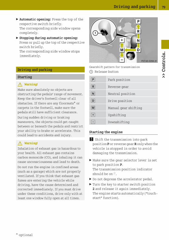
X Automatic opening: Press the top of therespective switch briefly.The corresponding side window openscompletely.
X Stopping during automatic opening:Press or pull up the top of the respectiveswitch briefly.The corresponding side window stopsimmediately.
Driving and parking
Starting
G Warning!
Make sure absolutely no objects areobstructing the pedals’ range of movement.Keep the driver’s footwell clear of all
obstacles. If there are any floormats* orcarpets in the footwell, make sure thepedals still have sufficient clearance.
During sudden driving or brakingmaneuvers, the objects could get caughtbetween or beneath the pedals and restrictyour ability to brake or accelerate. Thiscould lead to accidents and injury.
G Warning!
Inhalation of exhaust gas is hazardous toyour health. All exhaust gas containscarbon monoxide (CO), and inhaling it cancause unconsciousness and lead to death.
Do not run the engine in confined areas(such as a garage) which are not properlyventilated. If you think that exhaust gasfumes are entering the vehicle whiledriving, have the cause determined andcorrected immediately. If you must driveunder these conditions, drive only with atleast one window fully open at all times.
Gearshift pattern for transmission
: Release button
j Park position
k Reverse gear
i Neutral position
h Drive position
p Manual gear shifting
q Upshifting
± Downshifting
Starting the engine
! Shift the transmission into parkposition P or reverse gear R only when thevehicle is stopped in order to avoiddamaging the transmission.
X Make sure the gear selector lever is setto park position P.The transmission position indicatorshould be on P.
X Do not depress the accelerator pedal.X Turn the key to starter switch position
2 and release it again immediately.The engine starts automatically (“touch-start” function).
Driving and parking 79
>> C
ontr
ols.
* optional Z

Driving
X Depress the brake pedal.X Press release button : (Y page 79) to
disengage the gear selector lever lock.X Move the gear selector lever to drive
position D.D appears in the transmission positionindicator.
X Release the brake pedal.X Carefully depress the accelerator pedal.
G Warning!
On slippery road surfaces, never downshiftin order to obtain braking action. Thiscould result in drive wheel slip andreduced vehicle control. Your vehicle’s ABSwill not prevent this type of loss of control.
G Warning!
It is dangerous to shift the transmissionout of park position P or neutral positionN if the engine speed is higher than idlespeed. If your foot is not firmly on the brakepedal, the vehicle could accelerate quicklyforward or in reverse. You could losecontrol of the vehicle and hit someone orsomething. Only shift into gear when theengine is idling normally and when yourright foot is firmly on the brake pedal.
! Do not run a cold engine at high enginespeeds. Running a cold engine at highengine speeds may shorten the servicelife of the engine.
! Simultaneously depressing theaccelerator pedal and applying thebrakes reduces engine performance andcauses premature brake and drivetrainwear.
Reversing the vehicle
! Shift the transmission into reversegear R only when the vehicle is stoppedin order to avoid damaging thetransmission.
You can drive in reverse gear at a speedof up to 9 mph (15 km/h).
X Depress the brake pedal.X Press the release button (Y page 79) to
disengage the gear selector lever lock.X Move the gear selector lever to reverse
gear R.R appears in the transmission positionindicator.
X Release the brake pedal.X Carefully depress the accelerator pedal.
Parking
G Warning!
Do not park this vehicle in areas wherecombustible materials such as grass, hay orleaves can come into contact with the hotexhaust system. These materials could beignited and cause a vehicle fire.
Vehicle movement can cause seriouspersonal injury or damage to the vehicle orthe vehicle drivetrain. Therefore, alwaysdo the following before turning off theengine and leaving the vehicle:
RKeep right foot on the brake pedal.
REngage the parking brake.
RMove the gear selector lever to parkposition P.
RSlowly release the brake pedal.
RWhen parked on an incline, always turnthe front wheels towards the road curb.
80 Driving and parking>>
Con
trol
s.

RTurn the key to starter switch position 0and remove the key from the starterswitch.
RTake the key with you and lock the vehiclewhen leaving.
G Warning!
With the engine not running, there is nopower assistance for the brake and
steering* systems. In this case, it isimportant to keep in mind that aconsiderably higher degree of effort isnecessary to brake and steer the vehicle.Adapt your driving accordingly.
X Properly stop and park the vehicle.X Depress the brake pedal.X Engage the parking brake (Y page 81).
When the ignition is switched on or theengine is running, the brake warninglamp $ (USA only) or J (Canadaonly) in the instrument cluster comes on.
X Release the brake pedal.
Parking brake
The parking brake serves to secure thevehicle against rolling away when it isstationary or parked.
G Warning!
Engaging the parking brake while thevehicle is in motion can cause the rearwheels to lock up. You could lose control ofthe vehicle and cause an accident. Inaddition, the vehicle’s brake lights do notlight up when the parking brake is engaged.
X Releasing: Depress the brake pedal.
X Pull up slightly on parking brakelever : and press release button ;.
X Push parking brake lever : down as faras it will go.When the ignition is switched on or theengine is running, the brake warninglamp $ (USA only) or J (Canadaonly) in the instrument cluster goes out.
X Engaging: Pull up parking brakelever : firmly.When the ignition is switched on or theengine is running, the brake warninglamp $ (USA only) or J (Canadaonly) in the instrument cluster comes on.
G Warning!
Getting out of your vehicle with thetransmission not fully engaged in parkposition P is dangerous. When the engine isshut off and the brakes are released, thevehicle can be moved freely with the gearselector lever in all positions except parkposition P. Also, when parked on an incline,park position P alone may not prevent yourvehicle from moving, possibly hittingpeople or objects.
Always engage the parking brake inaddition to shifting to park position P.
When parked on an incline, always turn thefront wheels towards the road curb.
G Warning!
When leaving the vehicle, always remove thekey from the starter switch, take it with
Driving and parking 81
>> C
ontr
ols.
* optional Z

you, and lock the vehicle. Do not leavechildren unattended in the vehicle, or withaccess to an unlocked vehicle. Childrencould release the parking brake and/ormove the gear selector lever from parkposition P, either of which could result inan accident and/or serious personalinjury.
Brake pedal
The brake pedal has two brake circuitsindependent of each other. A brake servo isused during braking (when the engine isrunning) to increase pedal force.
G Warning!
Make sure absolutely no objects areobstructing the pedals’ range of movement.Keep the driver’s footwell clear of all
obstacles. If there are any floormats* orcarpets in the footwell, make sure thepedals still have sufficient clearance.
During sudden driving or brakingmaneuvers, the objects could get caughtbetween or beneath the pedals and restrictyour ability to brake or accelerate. Thiscould lead to accidents and injury.
G Warning!
Considerably more effort will be requiredto apply the brakes if
Rthe brake servo has failed
Ra brake circuit has failed
Rthe engine is switched off, e.g. fortowing the vehicle
The braking distance is likewise greater.
Make sure the engine is running wheneverthe vehicle is rolling. Have the brakesystem repaired at an authorized smartcenter, if there is a fault in the brakesystem.
: Brake pedal
If a brake circuit has failed (Y page 154),you must depress the brake pedal furtherdown to achieve the same effect and thebraking distance is increased.
i The brake servo will only function withthe engine switched on.
G Warning!
In the event of the vehicle needing to betowed, a significantly greater amount ofpedal pressure will be required when theengine is switched off.
Turning off the engine
G Warning!
Do not turn off the engine before thevehicle has come to a complete stop. Withthe engine not running, there is no power
assistance for the brake and steering*systems. In this case, it is important tokeep in mind that a considerably higherdegree of effort is necessary to brake andsteer the vehicle.
X Depress the brake pedal.X Press the release button (Y page 79) to
disengage the gear selector lever lock.X Move the gear selector lever to park
position P.
! Always engage the parking brake inaddition to shifting to park position P.
82 Driving and parking>>
Con
trol
s.
* optional

X Release the brake pedal.X Turn the key to starter switch position
0.
X Remove the key from the starter switch.The electronic immobilizer isactivated.
Transmission
Introduction
Your vehicle is equipped with a 5‑speedautomated transmission with manual orautomatic mode. For information ondriving with the transmission see also“Starting” (Y page 79).
G Warning!
Make sure absolutely no objects areobstructing the pedals’ range of movement.Keep the driver’s footwell clear of all
obstacles. If there are any floormats* orcarpets in the footwell, make sure thepedals still have sufficient clearance.
During sudden driving or brakingmaneuvers, the objects could get caughtbetween or beneath the pedals and restrictyour ability to brake or accelerate. Thiscould lead to accidents and injury.
Gear selector lever
Gearshift pattern for transmission
: Release button
j Park position
k Reverse gear
i Neutral position
h Drive position
p Manual gear shifting
q Upshifting
± Downshifting
The current gear selector lever positionappears in the transmission positionindicator. When M is selected the currentlyselected gear appears (Y page 89).
G Warning!
It is dangerous to shift the transmissionout of park position P or neutral positionN if the engine speed is higher than idlespeed. If your foot is not firmly on the brakepedal, the vehicle could accelerate quicklyforward or in reverse. You could losecontrol of the vehicle and hit someone orsomething. Only shift into gear when theengine is idling normally and when yourright foot is firmly on the brake pedal.
Shifting procedure
The transmission selects individual gearsautomatically, depending on:Rthe gear selector lever position D
(Y page 84)
Rthe position of the accelerator pedal(Y page 85)
Rthe vehicle speed
Ruphill or downhill grades
Press release button : (Y page 83) todisengage the gear selector lever lockwhen moving the gear selector lever from
Transmission 83
>> C
ontr
ols.
* optional Z

RP to R, N, or D
RR to P
RN to R or P
! Allow the engine to warm up under lowload use. Do not place full load on theengine until the operating temperaturehas been reached.
Shift into reverse gear R or parkingposition P only when the vehicle isstopped.
Avoid spinning of a drive wheel for anextended period when driving off onslippery road surfaces. Otherwise, thedrivetrain could be damaged, which isnot covered by the smart LimitedWarranty.
With manual gearshifting M selected(Y page 85), you can use the gear selectorlever or steering wheel gearshift controlto change the gears manually.
Gear selector lever positions
Effect
B Park position
Gear selector lever positionwhen the vehicle is parked.Place the gear selector leverin park position P only whenthe vehicle is stopped. Thepark position is not intendedto serve as a brake when thevehicle is parked.
Rather, the driver shouldalways engage the parkingbrake in addition to placingthe gear selector lever in parkposition P to secure thevehicle.
The key can only be removedfrom the starter switch withthe gear selector lever in parkposition P. With the keyremoved, the gear selectorlever is locked in parkposition P.
C Reverse gear
Shift into reverse gear R onlywhen vehicle is stopped.
A Neutral position
No power is transmitted fromthe engine to the drive axle.When the brakes are released,the vehicle can be movedfreely (pushed or towed).
7 Drive position
The transmission shiftsautomatically.
x Manual gearshifting
System-controlled automaticgearshifting is switched off.The driver has to change thegears manually.
84 Transmission>>
Con
trol
s.

The current gear selector lever positionappears in the transmission positionindicator (Y page 89).
Driving tips
Accelerator pedal position
Your driving style influences thetransmission’s shifting behavior:
Less throttle, earlier upshiftingMore throttle, later upshifting
Kickdown
Use kickdown when you want maximumacceleration.
X Press the accelerator pedal past thepoint of resistance.Depending on the engine speed thetransmission shifts into a lower gear.
X Ease on the accelerator pedal when youhave reached the desired speed.The transmission shifts up again.
Stopping
When you stop briefly, e.g. at trafficlights:
X Leave the transmission in gear.X Hold the vehicle with the brake.
When you stop for a longer period with theengine idling and/or on a hill:
X Engage the parking brake.X Move the gear selector lever to park
position P.
Working on the vehicle
G Warning!
When working on the vehicle, engage theparking brake and move the gear selectorlever to park position P. Otherwise thevehicle could roll away which could result
in an accident and/or serious personalinjury.
Driving off uphill
Your vehicle has a hill start assist system.
G Warning!
The hill start assist system is not designedto function as a parking brake and does notprevent the vehicle from moving whenparked on an incline.
Always engage the parking brake inaddition to shifting to park position P.
On uphill grades the hill start assistsystem maintains the pressure in the brakesystem for approximately one second afteryou have released the brake pedal.Therefore, you can start off smoothlywithout the vehicle moving immediatelyafter releasing the brake pedal.
X Release the brake pedal.X Apply sufficient pressure to the
accelerator pedal.
! After approximately one second, thehill start assist system stops braking thevehicle, which then can roll backwards.If you open the driver’s door within thistime, the hill start assistance isdeactivated and a warning signal sounds.
i The hill start assist system is inactiveif you start off with the parking brakeengaged.
Manual gearshifting
With manual gearshifting M selected,system-controlled automatic gearshiftingis switched off and you need to change thegears by upshifting or downshiftingmanually using the gear selector lever orthe steering wheel gearshift control12.
12 Model passion only.
Transmission 85
>> C
ontr
ols.
Z

! Allow the engine to warm up under lowload use. Do not place full load on theengine until the operating temperaturehas been reached.
Shift into reverse gear R or parkingposition P only when the vehicle isstopped.
Avoid spinning of a drive wheel for anextended period when driving off onslippery road surfaces. Otherwise, thedrivetrain could be damaged, which isnot covered by the smart LimitedWarranty.
Activating manual gearshifting
X Move the gear selector lever to driveposition D (Y page 83).
X Pull one of the shift paddles (Y page 86)towards you.
orX Move the gear selector lever to manual
gearshifting M (Y page 83).System-controlled automaticgearshifting is switched off.
You can upshift or downshift through thegears in succession.
The currently engaged gear appears inmultifunction display ; (Y page 86).
Upshifting
X Briefly push the gear selector leverforward in the + direction (Y page 83).
orX Pull right shift paddle = (Y page 86)
towards you.The transmission shifts to the nexthigher gear.
i With manual gearshifting M selected,the transmission shifts up only toprevent engine overrevving.
Downshifting
G Warning!
On slippery road surfaces, never downshiftin order to obtain braking action. Thiscould result in drive wheel slip andreduced vehicle control. Your vehicle’s ABSwill not prevent this type of loss of control.
X Briefly pull the gear selector leverbackward in the - direction (Y page 83).
orX Pull left shift paddle : (Y page 86)
towards you.The transmission shifts to the next lowergear.
Kickdown
You can use kickdown when you wantmaximum acceleration.
86 Transmission>>
Con
trol
s.

X Press the accelerator pedal past thepoint of resistance.Depending on the engine speed thetransmission shifts into a lower gear.
X When you have reached the desired speed,briefly push the gear selector leverforward in the + direction (Y page 83).
orX Pull right shift paddle = (Y page 86)
towards you.The transmission shifts to the nexthigher gear.
Deactivating manual gearshifting
X With drive position D selected: Pull andhold right shift paddle = (Y page 86)towards you for longer than two seconds.
orX With manual gearshifting M selected:
Move the gear selector lever to driveposition D (Y page 83).System-controlled automaticgearshifting is switched on again.
Emergency operation (limp-homemode)
In this mode only a certain gear or acertain gear combination can be selected.This mode is triggered in case oftransmission malfunctions and enables youdriving to the nearest workshop such as asmart center.
If vehicle acceleration becomes lessresponsive or sluggish or the transmissionno longer shifts, the transmission is mostlikely operating in limp-home (emergencyoperation) mode. The transmissionposition indicator flashes and the ¬symbol appears in the multifunctiondisplay.
Driving in limp-home mode:
X Move the gear selector lever to driveposition D (Y page 83).
X Continue to drive.X Have the transmission checked at an
authorized smart center as soon aspossible.
i It is possible that a gear combinationincluding the reverse gear can not beselected. Keep in mind when parking,that reversing the vehicle might beimpossible.
In case of a minor transmissionmalfunction, it might be possible to teach-in the transmission in order to restore thenormal transmission mode.
i If the attempt to teach-in thetransmission fails, you cannot continueto drive. Therefore we stronglyrecommend that you have thetransmission taught-in at a qualifiedworkshop or at an authorized smartcenter.
Teaching-in the transmission system:
X Stop the vehicle in a safe location.X Move the gear selector lever to park
position P.
X Turn off the engine.X Wait at least 30 seconds before
restarting.X Press the brake pedal.X Restart the engine
Three bars instead of P appear in themultifunction display.
X Wait at least 30 seconds.The transmission is taught in.
When teaching-in was successful:P appears in the multifunction displayagain and normal transmission operatingis restored.
X Continue to drive.
After an unsuccessful teaching-in:
Transmission 87
>> C
ontr
ols.
Z

Three bars instead of P appear in themultifunction display.
X Do not continue to drive.X Turn off the engine.X Engage the parking brake when leaving
the vehicle.X Contact Roadside Assistance or an
authorized smart center.
Instrument cluster
Multifunction display
The following displays and indicatorsappear in the multifunction display:
Multifunction display (U.S. vehicles)
: Main odometer display, or when active,days or distance to next maintenanceservice
; Transmission position indicator
= Digital clock
? Outside temperature display
A Fuel level display
B Status indicator with:
• Trip odometer display
• Maintenance service interval display
• Reserve fuel indicator
Multifunction display (Canada vehicles)
: Main odometer display, or when active,days or distance to next maintenanceservice
; Transmission position indicator
= Digital clock
? Outside temperature display
A Freeze warning
B Fuel level display
C Status indicator with:
• Trip odometer display
• Maintenance service interval display
• Reserve fuel indicator
G Warning!
No messages will be displayed if either theinstrument cluster or the multifunctiondisplay is inoperative.
As a result, you will not be able to seeinformation about your drivingconditions, such as speed, outsidetemperature, or warning/indicator lamps.Driving characteristics may be impaired.
If you must continue to drive, please do sowith added caution. Visit an authorizedsmart center as soon as possible.
Multifunction display illumination
The multifunction display illuminationcomes on when the starter switch is inposition 1. It goes out after approximately30 seconds when the starter switch is inposition 0.
88 Instrument cluster>>
Con
trol
s.

For adjusting the multifunction displayillumination, see “Adjusting instrumentcluster illumination” (Y page 93).
Main odometer display
Example illustration (U.S. vehicles)
i Canada vehicles: The main odometerdisplay shows km instead of miles.
The main odometer display appears in themultifunction display continuously.
Exception:The next maintenance service is due. Afterstarting the engine, days or distance tonext maintenance service will appearinstead of the main odometer display. Themain odometer display will reappear afterapproximately ten seconds.
For information on how to select themaintenance service interval display, see“Maintenance service interval display”(Y page 92).
Transmission position indicator
The following information is displayed inthe transmission position indicator:
RCurrent gear selector lever position
RCurrent engaged gear (when manualgearshifting selected)
i A flashing R in the display indicatesthat the gear selector lever is inposition R but the reverse gear is not
engaged. Stop the vehicle to let thereverse gear engage.
Example illustration (U.S. vehicles)
Display Function
P Gear selector lever in parkposition P
R Gear selector lever inposition R (Reverse gearengaged)
N Gear selector lever in neutralposition N
D Gear selector lever in driveposition D
When manual gearshifting is selected:
Display Function
1 First gear engaged
2 Second gear engaged
3 Third gear engaged
4 Fourth gear engaged
5 Fifth gear engaged
Instrument cluster 89
>> C
ontr
ols.
Z
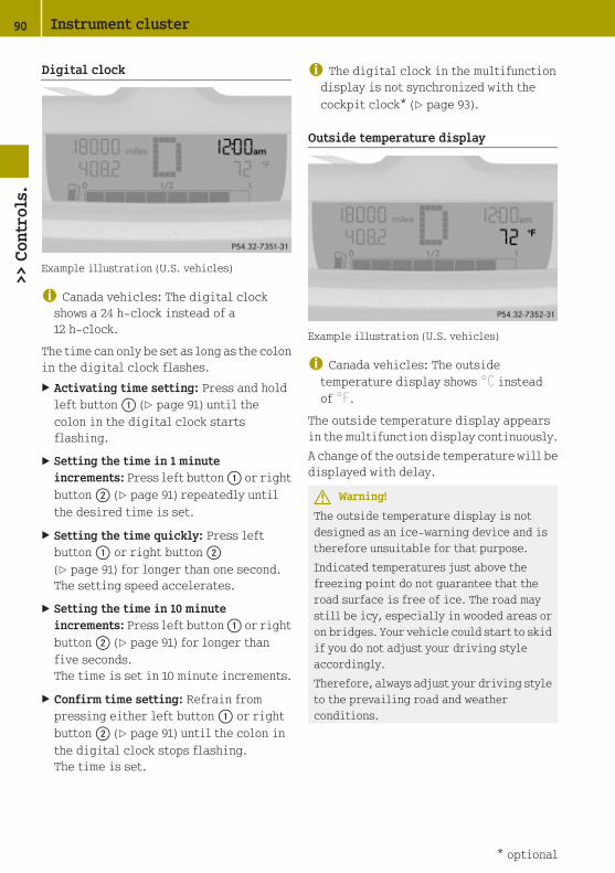
Digital clock
Example illustration (U.S. vehicles)
i Canada vehicles: The digital clockshows a 24 h-clock instead of a12 h-clock.
The time can only be set as long as the colonin the digital clock flashes.
X Activating time setting: Press and holdleft button : (Y page 91) until thecolon in the digital clock startsflashing.
X Setting the time in 1 minuteincrements: Press left button : or rightbutton ; (Y page 91) repeatedly untilthe desired time is set.
X Setting the time quickly: Press leftbutton : or right button ;(Y page 91) for longer than one second.The setting speed accelerates.
X Setting the time in 10 minuteincrements: Press left button : or rightbutton ; (Y page 91) for longer thanfive seconds.The time is set in 10 minute increments.
X Confirm time setting: Refrain frompressing either left button : or rightbutton ; (Y page 91) until the colon inthe digital clock stops flashing.The time is set.
i The digital clock in the multifunctiondisplay is not synchronized with thecockpit clock* (Y page 93).
Outside temperature display
Example illustration (U.S. vehicles)
i Canada vehicles: The outsidetemperature display shows °C insteadof °F.
The outside temperature display appearsin the multifunction display continuously.
A change of the outside temperature will bedisplayed with delay.
G Warning!
The outside temperature display is notdesigned as an ice-warning device and istherefore unsuitable for that purpose.
Indicated temperatures just above thefreezing point do not guarantee that theroad surface is free of ice. The road maystill be icy, especially in wooded areas oron bridges. Your vehicle could start to skidif you do not adjust your driving styleaccordingly.
Therefore, always adjust your driving styleto the prevailing road and weatherconditions.
90 Instrument cluster>>
Con
trol
s.
* optional

Freeze warning (Canada vehicles only)
When the outside temperature falls below3¥, the multifunction display makes youaware of the fact that the road may be icy.An additional freeze warning, i.e. an icecrystal symbol, in the multifunctiondisplay flashes. After 60 seconds, thefreeze warning stops flashing butcontinues to be displayed. When theoutside temperature rises above 3¥, thefreeze warning goes out.
Fuel level display
Example illustration (U.S. vehicles)
The fuel level display shows the tank’s fuellevel with the aid of eight segments. Thenumber of dark segments indicates the fuellevel in the tank. If all eight segments aredark, the tank is full.
You are driving on reserve fuel if there areno more than 1.0 US gal (3.78 l) of fuel in thetank.
If this occurs,
Rthe fuel pump symbol in the fuel leveldisplay flashes
Rthe reserve fuel indicator shows the fuellevel in the tank in 0.1 US gal (0.5 l)increments.
For selecting the reserve fuel indicator tobe displayed in the status indicator, see“Reserve fuel indicator” (Y page 92).
Selecting display for status indicator
You can select the information to bedisplayed in the status indicator:
RTrip odometer display (Y page 92)
RMaintenance service interval display(Y page 92)
RReserve fuel indicator (Y page 92)
: Selecting display for status indicator,setting the clock, activatingmaintenance service interval display
; Setting the clock, adjusting instrumentcluster illumination
Instrument cluster 91
>> C
ontr
ols.
Z
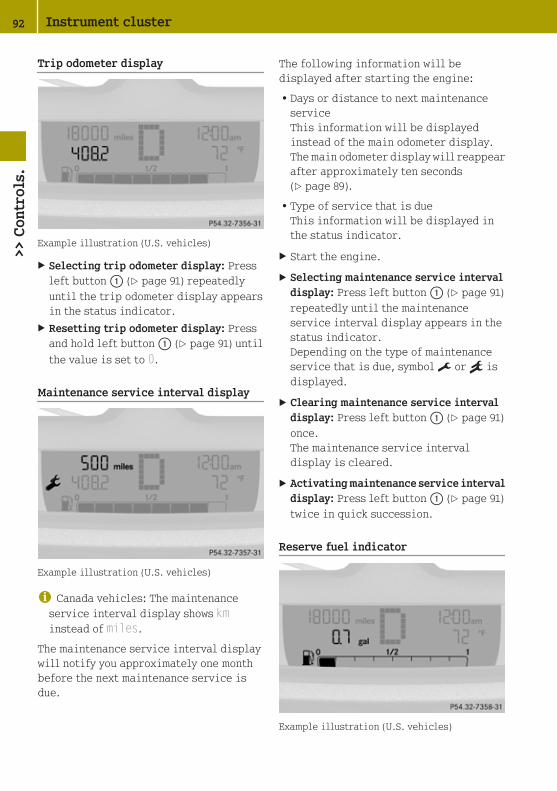
Trip odometer display
Example illustration (U.S. vehicles)
X Selecting trip odometer display: Pressleft button : (Y page 91) repeatedlyuntil the trip odometer display appearsin the status indicator.
X Resetting trip odometer display: Pressand hold left button : (Y page 91) untilthe value is set to 0.
Maintenance service interval display
Example illustration (U.S. vehicles)
i Canada vehicles: The maintenanceservice interval display shows kminstead of miles.
The maintenance service interval displaywill notify you approximately one monthbefore the next maintenance service isdue.
The following information will bedisplayed after starting the engine:
RDays or distance to next maintenanceserviceThis information will be displayedinstead of the main odometer display.The main odometer display will reappearafter approximately ten seconds(Y page 89).
RType of service that is dueThis information will be displayed inthe status indicator.
X Start the engine.
X Selecting maintenance service intervaldisplay: Press left button : (Y page 91)repeatedly until the maintenanceservice interval display appears in thestatus indicator.Depending on the type of maintenanceservice that is due, symbol ¬ or } isdisplayed.
X Clearing maintenance service intervaldisplay: Press left button : (Y page 91)once.The maintenance service intervaldisplay is cleared.
X Activating maintenance service intervaldisplay: Press left button : (Y page 91)twice in quick succession.
Reserve fuel indicator
Example illustration (U.S. vehicles)
92 Instrument cluster>>
Con
trol
s.

The reserve fuel indicator is onlydisplayed when driving on reserve fuel.
X Selecting reserve fuel indicator: Pressleft button : (Y page 91) repeatedlyuntil the reserve fuel indicator appearsin the status indicator.
Auxiliary instruments*
: Tachometer
; Cockpit clock
Tachometer*
The tachometer displays the engine speedin units of 1 000 rpm.
The tachometer can be turned byapproximately 90°.
The tachometer illumination comes on whenyou turn the key to starter switch position1.
! Do not hang any objects on thetachometer.
This could cause the tachometer to betorn from its mountings and damage it.
Cockpit clock*
The cockpit clock can be turned byapproximately 90°.
The cockpit clock illumination comes onwhen you turn the key to starter switchposition 1 and the parking lamps areswitched on.
The buttons for setting the time are on thetop of the cockpit clock.
X Setting the time back in 1 minuteincrements: Press button : repeatedlyuntil the desired time is set.
X Setting the time back quickly: Pressbutton : for longer than two seconds.The setting speed accelerates.
X Setting the time forward in 1 minuteincrements: Press button ; repeatedlyuntil the desired time is set.
X Setting the time forward quickly: Pressbutton ; for longer than two seconds.The setting speed accelerates.
! Do not hang any objects on the cockpitclock.
This could cause the cockpit clock to betorn from its mounting and damage it.
Adjusting instrument clusterillumination
You can adjust the illumination of theswitches, the dials in the instrumentcluster, the radio*, the climate control*panel and the auxiliary instruments*. Fivesettings are possible.
Instrument cluster 93
>> C
ontr
ols.
* optional Z

X Make sure the key is in starter switchposition 1.
X Switch on the parking lamps.X To brighten or dim illumination: Press
right button ; (Y page 91) repeatedlyuntil the desired setting is reached.The current setting is stored.
Audio system*
G Warning!
In order to avoid distraction which couldlead to an accident, the driver should entersystem settings with the vehicle at astandstill and operate the system only whenroad and traffic conditions permit. Alwayspay full attention to traffic conditionsfirst before operating system controlswhile driving.
Bear in mind that at a speed of just 30 mph(approximately 50 km/h), your vehicle iscovering a distance of 44 feet(approximately 14 m) every second.
G Warning!
Always select a volume that allows you tostill hear ambient sound in your immediatevicinity (e.g. horns, emergency rescuevehicles, police vehicles, etc.). You couldotherwise cause an accident.
G Warning!
If you wish to have a radio other than anoriginal smart radio fitted in yourvehicle, please always have the necessarywork performed at an authorized smartcenter.
This is particularly important if yourvehicle is fitted with a radiopreinstallation. Improper connection canresult in the failure of important vehiclefunctions, thereby endangering theoperating safety of your vehicle and thusyour own safety and that of other people.
The following pages contain a briefdescription of the audio systems availablefor the coupé and cabriolet.
The devices are described with their fullcomplement of equipment, including radiomode and CD changer* mode. Thedescription for your individual equipmentspecification applies.
Please refer to the separate operatinginstructions for detailed functions.
smart radio 9*
The smart radio 9 system contains thefollowing functions:
RRadio (FM/AM)
RCD player
RAUX-socket (Y page 95)
! Please be sure to read the operatinginstructions for the smart radio 9 beforeusing the unit. Familiarize yourselfwith the various functions of the unit sothat you are able to operate it easily,reliably and correctly at any time.
: On/off switch
; Random button
= Station buttons
? Display
A CD eject button
B Control panel for selecting functionsfor radio, CD, AUX
94 Audio system*>>
Con
trol
s.
* optional

C Control panels for selecting functionsfor tone settings, menu, frequency band
D Volume
smart radio 10*
The smart radio 10 system contains thefollowing functions:
RRadio (FM/AM)
RMP3 player
RCD changer
RAUX-socket (Y page 95)
! Please be sure to read the operatinginstructions for the smart radio 10before using the unit. Familiarizeyourself with the various functions of theunit so that you are able to operate iteasily, reliably and correctly at anytime.
: On/off switch
; CD load button
= Station buttons
? Display
A CD eject button
B Control panel for selecting functionsfor radio, radio CD, CD changer, MP3
C Control panels for selecting functionsfor tone settings, menu, frequency band
D Volume
smart sound package*
The smart sound package supplements theexisting speakers with additionalspeakers (including active subwoofer).
You can connect mobile audio devices suchas an MP3 player via smart MP3 interface*(AUX-socket*) using a commerciallyavailable 3.5 mm socket plug.
The AUX-socket is located in the glove boxon the passenger side.
: AUX-socket
HVAC (Heating, Ventilation, AirConditioning)
Notes on HVAC
G Warning!
Follow the recommended settings forheating and cooling given on the followingpages. Otherwise the windows could fog up,impairing visibility and endangering youand others.
Air conditioning with climate control*
The air conditioning improves the level ofcomfort when driving at high outsidetemperatures by cooling anddehumidifying the air.
Nearly all dust particles, pollutants, arefiltered out by an integrated particlefilter before outside air enters thepassenger compartment through the airdistribution system. It also operates when
HVAC (Heating, Ventilation, Air Conditioning) 95
>> C
ontr
ols.
* optional Z

the air conditioning is switched off andyou have switched on the blower.
The air conditioning only works when theengine is running and the blower isswitched on. Maximum effectiveness isachieved if you drive with the windowsclosed.
i In warmer weather, ventilate thepassenger compartment for a shortperiod of time before utilizing the airconditioning.
Control panels HVAC
Heating
: Air volume control
; Rear window defroster switch
= Air distribution control
? Temperature control
96 HVAC (Heating, Ventilation, Air Conditioning)>>
Con
trol
s.

Air conditioning with climate control*
: Air volume control
; Air conditioning switch
= Rear window defroster switch
? Air recirculation switch
A Temperature control
B Air distribution control
Switching HVAC on/off
Heating
Control panel (Y page 96).
X Switching on: Make sure the key is instarter switch position 1.
X Push temperature control ? up.
X Switching off: Push temperaturecontrol ? fully down.
Air conditioning with climate control*
Control panel (Y page 97).
X Make sure the engine is running.
X Switching on: Push air volumecontrol : to level 1 or higher.
X Press air conditioning switch ;.The indicator lamp in air conditioningswitch ; comes on.
X Switching off: Press air conditioningswitch ; once more.The indicator lamp in air conditioningswitch ; goes out.
i The stored status is restored, if youswitch on the ignition again.
i The air condition will be suspendedtemporarily:
Rif the engine speed is too low
Rwhen driving off
The air condition is switched off:
Rat a coolant temperature of more than239¦ (115¥)
Rat outside temperatures below 38¦(3¥)
Setting the temperature
Heating
Control panel (Y page 96).
i You should raise or lower thetemperature setting in smallincrements.
X Increasing or decreasing: Pushtemperature control ? up or down.
Rapid cooling
X Push air volume control : fully up.
X Turn air distribution control = toposition P.
X Push temperature control ? fully down.
X Adjust the air vents as desired.
HVAC (Heating, Ventilation, Air Conditioning) 97
>> C
ontr
ols.
* optional Z

Rapid heating
X Push air volume control : to level 3.
X Turn air distribution control = to aposition between z and O.
X Push temperature control ? fully up.
X Adjust the air vents towards theoccupants.
Air conditioning with climate control*
Control panel (Y page 97).
i You should raise or lower thetemperature setting in smallincrements, preferably starting at 70¦(21¥).
X Increasing or decreasing: Pushtemperature control A up or down.
Adjusting air vents
G Warning!
When operating the heating or air
conditioning with climate control*, theair that enters the passenger compartmentthrough the air vents can be very hot or verycold (depending on the set temperature).This may cause burns or frostbite onunprotected skin in the immediate area ofthe air vents. Always keep sufficientdistance between unprotected parts of thebody and the air vents. If necessary, use theair distribution control to direct the airto air vents in the vehicle interior that arenot in the immediate area of unprotectedskin.
To make sure the heating or airconditioning with climate control* worksproperly, please observe the following:
RKeep the air intake grill free fromdeposits, e.g. ice or snow, to ensure that
fresh air can flow freely into the vehicleinterior.
RDo not obstruct air vents or ventilationgrilles in the vehicle interior.
i For draft-free ventilation, move thesliders for the center air vents and sideair vents to the middle position.
Center air vents
: Left center air vent, adjustable
; Control panel
= Right center air vent, adjustable
X Adjusting: Turn slider : or = to theleft, right, up, or down.
X Opening: Turn slider : or = inwardstowards the center console.
X Closing: Turn slider : or = fullyoutwards towards the side window.
98 HVAC (Heating, Ventilation, Air Conditioning)>>
Con
trol
s.
* optional

Side air vents
Side air vents on driver’s side illustrated asexample
: Left side defroster air vent, fixed
; Left side air vent, adjustable
X Adjusting: Turn slider ; to the left,right, up, or down.
X Opening: Turn slider ; inwards towardsthe center console.
X Closing: Turn slider ; fully outwardstowards the side window.
Adjusting air distribution
Symbol Function
z Directs air to the windshieldand side windows
O Directs air to the footwellsand air distribution isreduced at the center and sideair vents
P Directs air through the centerand side air vents
i You can also turn the air distributioncontrol to a position between twosymbols.
Heating
Control panel (Y page 96).
X Turn air distribution control = to thedesired symbol.The air distribution is controlleddepending on the position of the airdistribution control.
Air conditioning with climate control
Control panel (Y page 97).
X Turn air distribution control B to thedesired symbol.The air distribution is controlleddepending on the position of the airdistribution control.
Adjusting air volume
The air volume is controlled depending onthe blower speed selected. Five blowerspeeds are available.
0 Off
1 Slow
2 Medium
3 High/defrosting
4 Maximum
X Increasing or decreasing: Push airvolume control : up or down.
Defrosting
G Warning!
Never drive with iced up or foggedwindows. Visibility will be significantlyimpaired. Impaired visibility couldendanger yourself and others. This mayprevent you from observing the trafficconditions, thereby causing an accident.
HVAC (Heating, Ventilation, Air Conditioning) 99
>> C
ontr
ols.
Z

The best defrosting of windows is achievedif the ice is completely removed from thewindows manually with an ice scraperbefore starting the engine.
Heating
Control panel (Y page 96).
X Switching on: Push air volumecontrol : to level 3.
X Turn air distribution control = toposition z.
X Push temperature control ? fully up.
Air conditioning with climate control
Control panel (Y page 97).
X Switching on: Push air volumecontrol : to level 3.
X Turn air distribution control B toposition z.
X Push temperature control A fully up.
Rear window defroster
The rear window defroster serves to de-icethe rear window quickly and clear the viewif the rear window is fogged.
The rear window defroster uses a largeamount of power. To keep battery drain to aminimum, switch off the rear windowdefroster as soon as the rear window isclear. The rear window defroster isautomatically deactivated afterapproximately 10 minutes of operation.
X Make sure the key is in starter switchposition 1.
X Switching on: Press rear windowdefroster switch :.The indicator lamp in rear windowdefroster switch : comes on.
X Switching off: Press rear windowdefroster switch : once more.The indicator lamp in rear windowdefroster switch : goes out.
Air recirculation mode*
Switch to air recirculation mode13 toprevent unpleasant odors from entering thevehicle from the outside (e.g. beforedriving through a tunnel). This setting cutsoff the intake of outside air andrecirculates the air in the passengercompartment.
G Warning!
When the air recirculation mode isswitched on, windows can fog on the insideimmediately. Fogged windows impairvisibility, endangering you and others. Ifthe windows begin to fog on the inside,switching off the air recirculation modeimmediately should clear interior windowfogging. If interior window foggingpersists, make sure the air conditioning isswitched on, turn air distribution control
13 Vehicles with air conditioning with climate control* only.
100 HVAC (Heating, Ventilation, Air Conditioning)>>
Con
trol
s.
* optional

B to position z and increase the airvolume using air volume control :.
Control panel (Y page 97).
X Switching on: Press air recirculationswitch ?.The indicator lamp in air recirculationswitch ? comes on.
X Switching off: Press air recirculationswitch ? once more.The indicator lamp in air recirculationswitch ? goes out.
Loading and storing
Cup holder
G Warning!
In order to help prevent spilling liquidson vehicle occupants and/or vehicleequipment, only use containers that fitinto the cup holder. Use lids on opencontainers and do not fill containers to aheight where the contents, especially hotliquids, could spill during braking,vehicle maneuvers, or an accident. Liquidsspilled on vehicle occupants may causeserious personal injury. Liquids spilledon vehicle equipment may cause damage notcovered by the smart Limited Warranty.
Keep in mind that objects placed in a cupholder may come loose during braking,vehicle maneuvers, or an accident and bethrown around in the vehicle interior.Objects thrown around in the vehicleinterior may cause an accident and/orserious personal injury.
The cup holder can be used to safely storesealed drink bottles, containers with a lid,or beverage cans.
! Do not use the cup holder as an ashtray.Otherwise it could be damaged.
The cup holder : is located in front of thelower center console.
You can store two cups, drink bottles orbeverage cans of different diameters inthe cup holder.
The cup holder insert* ; can be removedin order to store two cups, drink bottles orbeverage cans of the same diameter.
i Clean the cup holder with a damp cloth.
Cargo compartment cover blind withparcel net bag
This feature is only available in Canadafor the model passion.
G Warning!
The cargo compartment cover blind is notintended to secure heavy objects in theevent of an accident. For this reason, heavyobjects must be tied down.
Vehicle occupants could be injured byobjects being thrown around in the vehiclein the event of
Rsharp braking
Ra change of direction
Ran accident
G Warning!
Do not place any objects on the mountedcargo compartment cover blind.
Vehicle occupants could be injured byobjects being thrown around in the vehiclein the event of
Loading and storing 101
>> C
ontr
ols.
* optional Z

Rsharp braking
Ra change of direction
Ran accident
G Warning!
Only place light loads in the parcel netbag. Do not transport heavy, sharp-edged orfragile objects in the parcel net bag. Theparcel net bag cannot sufficiently secureloads in an accident.
Vehicle occupants could be injured byobjects being thrown around in the vehiclein the event of
Rsharp braking
Ra change of direction
Ran accident
Observe the loading guidelines.
The cargo compartment cover blind
Rserves to protect objects that are storedin the vehicle’s cargo compartment fromprying eyes
Rprevents smaller objects frompenetrating into the passengercompartment from the cargocompartment; however, it is not intendedto act as a load restraining device
The parcel net bag
Ris for storing small, lightweight objects
Rprevents small objects from slidingaround inside the passengercompartment
! If objects are placed on the cargocompartment cover blind when mounted,the cover may be damaged.
Fitting
If you wish to use cargo compartment coverblind : as normal, assemble it in topmountings ;. If you do not need the cargocompartment cover blind, insert in bottommountings =.
X Open the tailgate.X Secure cargo compartment cover
blind : at the front of the cargocompartment with the parcel net bag.
X Insert cargo compartment coverblind : on the right-hand side in topmounting ; or in bottom mounting =.
X Push handle ? to the right in thedirection of the arrow.
X Insert cargo compartment coverblind : in top mounting ; or bottommounting = in the left-hand sidepaneling and release handle ?.
X Cargo compartment cover blind :engages.
102 Loading and storing>>
Con
trol
s.

X Pull parcel net bag A down slightly andsecure with the hook and loop fastener.
X Remove in reverse order.
Controls
X Closing: Take hold of cargo compartmentcover blind : in the middle and pullbackwards.
X Guide cargo compartment coverblind : into the rear right and leftmountings ;.
X Opening: Take hold of cargo compartmentcover blind : in the middle, pullbackwards, and remove from rearmountings ;.
X Guide cargo compartment coverblind : into position.
Coat hooks
The coat hooks are located at the rear roofrail on the driver’s and passenger side.
Coat hook on driver’s side
: Coat hook
Storage compartments
G Warning!
To help avoid personal injury during acollision or sudden maneuver, exercisecare when storing objects in the vehicle.Put luggage or cargo in the cargocompartment if possible. Do not pileluggage or cargo higher than the seatbackrests.
Rbraking
Rvehicle maneuvers
Ran accident
Do not store objects under the driver’s seat.Objects stored under the driver’s seat canslide forward into driver’s foot well duringbraking and get caught between or beneaththe pedals. This could restrict your abilityto brake or accelerate and could lead toaccidents and injury.
Coin holder
The coin holder is located in front of thegear selector lever.
Loading and storing 103
>> C
ontr
ols.
Z

coupé illustrated as example
: Coin holder
Door pockets
The door pockets are located in the driver’sand passenger door.
: Door pocket
Storage trays next to the steering wheel
The storage trays are located to the left andright of the steering wheel.
: Storage tray
Glove box
The glove box is located in front of thepassenger seat.
X Opening: Pull on glove box lidrelease ; and fold down the glove boxlid.
X Closing: Lift up the glove box lid with abit of force until it engages.
X Locking: Insert the key into glove boxlock : and turn counterclockwise.
X Unlocking: Insert the key into glove boxlock : and turn clockwise.
Storage compartment in the tailgate(coupé only)
You can store small objects in the storagecompartment in the tailgate.
104 Loading and storing>>
Con
trol
s.

X Open the tailgates.X Pull handle : on the inside of the
tailgate backward.X Lift up the storage compartment cover in
direction of arrow.
Loading instructions
G Warning!
Transport heavy or hard objects in thecargo compartment, not in the passengercompartment.
Always fasten items being carried assecurely as possible using fasteningmaterials appropriate for the weight andsize of the load.
In an accident, during hard braking orsudden maneuvers, loose items may bethrown around inside the vehicle, causinginjury to vehicle occupants.
G Warning!
To help avoid personal injury during acollision or sudden maneuver, exercisecare when storing objects in the vehicle.Put luggage or cargo in the cargocompartment if possible. Do not pileluggage or cargo higher than the seatbackrests.
Keep compartment lids closed. This willhelp to prevent stored objects from beingthrown about and injuring vehicleoccupants during
Rbraking
Rvehicle maneuvers
Ran accident
G Warning!
No racks or loads may be secured to the roofof the vehicle, as
Rthe panorama roof* may be damaged, thusinjuring persons
Rthis can have a substantial adverseeffect on the driving dynamics of thevehicle, thus causing accidents
Rthe rack and/or the load could detach andthrough this cause an accident or otherpeople could be injured by the load and/or rack that has fallen off
G Warning!
Make sure the tailgate is closed when theengine is running and while driving.Among other dangers, deadly carbonmonoxide (CO) gases may enter vehicleinterior resulting in unconsciousness anddeath.
G Warning!
Do not store any flammable substancesinside the vehicle that could ignite andstart a fire.
G Warning!
The manufacturer has not approved yourvehicle for towing a trailer. A trailer canpermanently impair driving safety.
The gross vehicle weight which is theweight of the vehicle including fuel, tools,installed accessories, passengers, andluggage/cargo must never exceed the loadlimit and the Gross Vehicle Weight Rating(GVWR) for your vehicle as specified on theplacard located on the driver’s doorB‑pillar (Y page 202). In addition, theload must be distributed in such a way sothat the weight on each axle never exceedsthe Gross Axle Weight Rating (GAWR) for thefront and rear axle. The GVWR and GAWR foryour vehicle are indicated on thecertification label which can be found onthe driver’s door B‑pillar.
Loading and storing 105
>> C
ontr
ols.
* optional Z

For more information, see “Loading thevehicle” (Y page 124).
The handling characteristics of a fullyloaded vehicle depend greatly on the loaddistribution. It is therefore recommendedto load the vehicle with the heaviest itemsbeing placed towards the front of thevehicle.
Please pay attention to and comply with thefollowing instructions when loading thevehicle and transporting cargo:RAlways place items being carried
against seat backrests, and fasten themas securely as possible.
RThe heaviest portion of the cargo shouldalways be kept as low as possible againstseat backrests.
RDo not stack loads higher than the topedge of the head restraints.
RMake sure no luggage/cargo items can getabove or next to the driver’s and/orpassenger seat into the passengercompartment.
RMake sure luggage/cargo is properlysecured.
RAlways use, if so equipped, cargo net*when transporting cargo.
Useful features
Sun visors
The sun visors protect you from sun glarewhile driving.
Glare through the windshield
X Swing sun visor : down.
Glare through a side window
X Swing sun visor : down.
X Disengage sun visor : frommounting ;.
X Pivot sun visor : to the side.
Sun screen* (coupé only)
The sun screen provides protection fromsun rays and from heat generated by thepanorama roof*.
The sun screen can be adjusted to anydesired position.
X Opening or closing: Move sun screen :forward or backward using the handle.
106 Useful features>>
Con
trol
s.
* optional

Auxiliary power outlet
The auxiliary power outlet supplies powerto the following electrical accessorieswhen the key is turned to starter switchposition 1:Rthe cigarette lighter*, available in
conjunction with the ashtray*
Rthe electric air pump, available inconjunction with the tire repair kit*
Rother consumers which operate up to amaximum of 60 W
! The auxiliary power outlet canaccommodate 12V DC electricalaccessories designed for use with thestandard “cigarette lighter” plug type.
Keep in mind, however, that connectingaccessories to the auxiliary power outlet(for example extensive connecting anddisconnecting, or using plugs that do notfit properly) can damage the auxiliarypower outlet. With the auxiliary poweroutlet damaged, the cigarette lighter*may no longer be able to be placed in theheating (pushed-in) position, or may popout before it is hot enough.
The auxiliary power outlet is located in thelower center console.
Auxiliary power outlet
X Turn the key to starter switch position1.
! Please observe the safety instructionsgiven in the respective operatinginstructions.
Please note thatRif using the auxiliary power outlet the
maximum current drawn does not exceed5 A
Rthe electric air pump can be connectedto the auxiliary power outlet for the timeit takes to inflate the tire without anyproblem
Rthe vehicle battery will discharge whencurrent is drawn
Wheel cover*
Steel rim with wheel cover
X Mounting: Position wheel coveraperture : so valve ; fits through.
X Push the wheel cover evenly onto thewheel rim with both hands.
X Check that the wheel cover is fixedsecurely to the wheel rim.
X Removing: Pull wheel cover : off of therim.
If necessary, use a suitable tool to prythe wheel cover off.
Useful features 107
>> C
ontr
ols.
* optional Z

108

>> O
pera
tion
.
The first 1000 miles (1500 km) .............. 110
At the gas station ............................. 110
Engine compartment .......................... 111
Front compartment ........................... 114
Tires and wheels .............................. 118
Winter driving ................................ 136
Driving instructions ........................ 138
Driving abroad ................................ 144
Vehicle care ................................... 145

The first 1000 miles (1500 km)
In the Operation section you will finddetailed information on operating,maintaining and caring for your vehicle.
The more cautiously you treat your vehicleduring the break-in period, the moresatisfied you will be with its performancelater on.RDrive your vehicle during the first
1 000 miles (1 500 km) at varying butmoderate vehicle and engine speeds.
RDuring this period, avoid heavy loads(full throttle driving) and excessiveengine speeds (no more than 2/3 ofmaximum rpm in each gear).
RShift gears in a timely manner.
RDo not attempt to slow the vehicle downby shifting to a lower gear.
RAvoid accelerating by kickdown.
After 1 000 miles (1 500 km), you maygradually increase vehicle and enginespeeds to the permissible maximum.
All of the above instructions also applywhen driving the first 1 000 miles (1 500 km)after the engine has been replaced.
i Always obey applicable speed limits.
At the gas station
Refueling
G Warning!
Gasoline is highly flammable andpoisonous. It burns violently and can causeserious personal injury.
Never allow sparks, flame or smokingmaterials near gasoline!
Turn off the engine before refueling.
Whenever you are around gasoline, avoidinhaling fumes and skin or clothingcontact. Extinguish all smoking materials.
Direct skin contact with fuels and theinhalation of fuel vapors are damaging toyour health.
! Do not put diesel in vehicles withgasoline engines. Do not mix gasolinewith diesel. Even small quantities ofdiesel will damage the injection system.Damage caused by adding diesel will notbe covered by the smart LimitedWarranty.
If diesel has mixed with gasoline, do notstart the engine. Otherwise the catalyticconverter will be irreparably damaged.
Contact an authorized smart center orRoadside Assistance immediately andhave the vehicle towed.
! Damage resulting from mixing gasolinewith diesel fuel is not covered by thesmart Limited Warranty.
The fuel filler flap is located on thepassenger side towards the rear. Locking/unlocking the vehicle with the keyautomatically locks/unlocks the fuel fillerflap.
i In case the central locking system doesnot release the fuel filler flap, or theopening mechanisms is clamping,contact Roadside Assistance or anauthorized smart center.
: Opening the fuel filler flap
; Inserting the fuel filler cap
= Fuel filler cap
110 At the gas station>>
Ope
rati
on.

? Fuel type label
A Holder
X Turn off the engine.X Remove the key from the starter switch.X Open the fuel filler flap by pulling at the
point indicated by arrow :.
X Turn fuel filler cap = counterclockwiseand hold on to it until possible pressureis released.
X Take off fuel filler cap =.
! The fuel filler cap is tethered to thefuel filler flap. Do not drop the fuelfiller cap. It could damage the vehiclepaint finish.
X Insert fuel filler cap = in direction ofarrow ; into holder A on the inside ofthe fuel filler flap.
X Fully insert filler nozzle unit andrefuel.
X Only fill your tank until the filler nozzleunit cuts out — do not top off oroverfill.
G Warning!
Overfilling of the fuel tank may createpressure in the system which could cause agas discharge. This could cause the gas tospray back out when removing the fuel pumpnozzle, which could cause personal injury.
X Replace fuel filler cap =.
X Turn fuel filler cap = clockwise untilthe handle grip overturns.
i Make sure to close the fuel filler flapbefore locking the vehicle as the fuelfiller flap locking pin prevents closingafter you have locked the vehicle.
X Close the fuel filler flap.
You should hear the latch close shut.
i Only use premium unleaded gasolinewith a minimum Posted Octane Rating of91 (average of 96 RON/86 MON).
Information on gasoline quality cannormally be found on the fuel pump.Please contact gas station personnel incase labels on the pump cannot be found.
For more information on gasoline, see“Premium unleaded gasoline”(Y page 211) and “Fuel requirements”(Y page 212), or contact an authorizedsmart center.
Check regularly and before a long trip
For information on quantities andrequirements of operating agents, see“Service fluids and capacities”(Y page 209).
Check the following:
REngine oil level (Y page 112)
RTire inflation pressure (Y page 120)
RCoolant level (Y page 115)
RVehicle lighting (Y page 168)
RWindshield washer system (Y page 116)
RBrake fluid (Y page 117)
Engine compartment
Engine compartment cover
Open the engine compartment cover tocheck the engine oil level and if necessary,to add engine oil.
G Warning!
High outside temperature, stop-and-gotraffic, driving on long uphill grades ordriving at high engine speed may increasethe temperature in the enginecompartment. Therefore, the enginecompartment cover and parts in the areaaround the engine compartment cover maybe hot. Parts of the engine can become veryhot. To prevent burns, let the engine cooloff completely before touching the enginecompartment cover, parts in the area
Engine compartment 111
>> O
pera
tion
.
Z

around the engine compartment cover, andparts of the engine.
X Turn off the engine.X Engage the parking brake.X Open the tailgate.
G Warning!
Exercise extreme caution if you see flamesor smoke coming from the enginecompartment. Move away from the vehicleand call the fire department.
If the coolant temperature warning lampindicates that the engine is overheated, donot attempt to open the engine compartmentcover. Move away from the vehicle and waituntil the engine has cooled before openingthe engine compartment.
G Warning!
To help prevent personal injury, stay clearof moving parts when the enginecompartment cover is open and the engineis running.
G Warning!
The engine is equipped with atransistorized ignition system thatutilizes high voltage. Don not touch anycomponents (ignition coils, spark plugsockets, diagnostic socket) of the ignitionsystem
Rwhile the engine is running
Rwhile starting the engine
Rif ignition is “on” and the engine isturned manually
X Opening: Grasp the strap on cargocompartment floor :.
X Lift cargo compartment floor : with thestrap.
X Engage hook ? into top mounting ofcargo compartment cover blind A.
X Remove fastening screw ;.
X Remove engine compartment cover =.
X Closing: Slide engine compartment cover= forward into the tabs provided.
X Tighten fastening screw ;.
X Disengage hook ? from top mountingA.
X Fold cargo compartment floor : backdown.
X Push the right hand and left hand cargocompartment floor edges under the edgesof the side panels.
X Close the tailgate.
Engine oil
The amount of oil your engine needs willdepend on a number of factors, includingdriving style. Increased oil consumptioncan occur when the vehicle is new or thevehicle is driven at higher engine speedsfrequently.
Engine oil consumption checks should onlybe made after the vehicle break-in period.
112 Engine compartment>>
Ope
rati
on.

! Do not use any special lubricantadditives, as these may increase wearand damage the drive assemblies. Usingspecial additives not approved by smartmay cause damage not covered by thesmart Limited Warranty. Moreinformation on this subject is availableat any smart center.
Checking engine oil level
! Check the engine oil level at regularintervals.
When checking the engine oil level
Rthe vehicle must be parked on levelground
Rthe vehicle must have been stationary forat least five minutes with the engineturned off
X Turn off the engine.X Engage the parking brake.X Open the tailgate.X Open the engine compartment cover
(Y page 111).
The oil dipstick is located in the enginecompartment on the passenger side.
X Pull out oil dipstick :.
X Wipe oil dipstick : clean with a cleancloth.
X Fully insert oil dipstick : into thedipstick guide tube.
X Pull out oil dipstick : again afterapproximately one minute to obtainaccurate reading.
The oil level is correct when it isbetween lower mark = (minimum) andupper mark ; (maximum) on both sidesof oil dipstick :.
X Fully insert oil dipstick : into thedipstick guide tube again.
X If necessary, add engine oil(Y page 113).
i The filling quantity between the upperand lower marks on the oil dipstick isapproximately 1.1 US qt (1.0 l).
Adding engine oil
! Only use approved engine oils and oilfilters required for vehicles withMaintenance System. For a listing ofapproved engine oils and oil filterscontact an authorized smart center.
Using engine oils and oil filters ofspecification other than those expresslyrequired for the Maintenance System, orchanging of oil and oil filter at changeintervals longer than those called for bythe Maintenance System will result inengine or emission control systemdamage not covered by the smart LimitedWarranty.
G Warning!
When adding engine oil, always use a funnelto avoid spilling oil on any hot parts suchas the catalytic converter or exhaustsystem.
If this should happen, however, the enginemust be thoroughly cleaned before youcontinue your trip. The engine oil couldotherwise ignite.
Engine compartment 113
>> O
pera
tion
.
Z

The filler cap is located in the enginecompartment on the passenger side.
X Unscrew filler cap : from the fillerneck.
X Add engine oil as required.
Do not add more than 0.53 US qt (0.5 l)engine oil at a time.
X Wait one minute until the engine oil hasrun into the oil pan.
X Check the engine oil level once more.X Add engine oil once more if necessary.
Be careful not to spill any oil when addingto avoid environmental damage caused byoil entering the ground and water.
! Excess engine oil must be siphoned ordrained off. It could cause damage to theengine or emission control system notcovered by the smart Limited Warranty.
X Screw filler cap : back on the fillerneck.
X Close the engine compartment cover(Y page 111).
Front compartment
Service flap
Remove the service flap to check thecoolant level, windshield washer reservoirlevel, and brake fluid level.
Insert the service flap on the front of thevehicle so that it does not get damaged ordirty.
G Warning!
Always turn the key to starter switchposition 0 and remove the key from thestarter switch before opening the serviceflap.
If the windshield wipers shouldinadvertently be switched on, you could beseriously injured by the wiper washerdrive, which is located just below theservice flap.
G Warning!
Make sure the service flap is locked whiledriving. Otherwise, the service flap couldbecome detached and pose a hazard to youor others.
G Warning!
To help prevent personal injury, stay clearof moving parts when the service flap isopen.
The radiator fan may continue to run forapproximately 30 seconds or may evenrestart after the engine has been turnedoff. Stay clear of fan blades.
! Check the fill levels at regularintervals.
! Carefully remove ice, snow, and anyother deposits from the air intakegrilles above the service flap to ensureair intake at all times.
X Park the vehicle on level ground.X Turn off the engine.X Engage the parking brake.
114 Front compartment>>
Ope
rati
on.

X Removing: Fold both levers : outward indirection of the arrows as far as they willgo.
X Lift the front end of service flap ;.
X Remove service flap ;.
X Inserting: Insert hooks = on the back ofservice flap ; completely intoopenings ?.
X Remounting: Lift service flap ; out ofopenings ? (Y page 115).
X Insert tabs A on the back of serviceflap ; completely into openings B.
X Closing: Push front end of serviceflap ; down.
X Fold levers : inward in direction of thearrows as far as they will go.
Coolant
G Warning!
In order to avoid potentially serious burns:
RUse extreme caution when opening theservice flap if there are any signs ofsteam or coolant leaking from the
Front compartment 115
>> O
pera
tion
.
Z

cooling system, or if the coolanttemperature warning lamp ? in theinstrument cluster indicates that thecoolant is overheated.
RDo not remove pressure cap on coolantreservoir if coolant temperature isabove 158¦ (70¥). Allow engine to cooldown before removing cap. The coolantreservoir contains hot fluid and is underpressure.
RUsing a rag, slowly open the cap
approximately 1/2 turn to relieve excess
pressure. If opened immediately,scalding hot fluid and steam will beblown out under pressure.
The engine coolant is a mixture of waterand anticorrosion/antifreeze. To check thecoolant level the vehicle must be parked onlevel ground and the engine must havecooled down. For more information, see“Coolants” (Y page 213).
Checking coolant level
X Remove the service flap and insert it onthe front of the vehicle (Y page 114).
The coolant reservoir is located in thefront compartment on the driver’s side.
X Allow the radiator to cool down for atleast 30 minutes.
X Using a rag, turn pressure cap : slowlyapproximately one half turn
counterclockwise to release any excesspressure.
X Continue turning pressure cap :counterclockwise and remove it.
The coolant level is correct if the level
Rfor cold coolant: reaches markingbar ; visible through the fillingopening
Rfor warm coolant: is approximately0.6 in (1.5 cm) higher
X If necessary, add coolant.
Adding coolant
X Add coolant as required. The coolantlevel may not exceed the maximum fillinglevel.
X Replace and tighten pressure cap :.
X Remount the service flap and close it(Y page 114).
Windshield/rear window washer system
Both the windshield and the rear window14
washer are supplied from the windshieldwasher reservoir.
The recommended minimum filling level is1.06 US qt (1.0 l).
X Remove the service flap and insert it onthe front of the vehicle (Y page 114).
14 Coupé only.
116 Front compartment>>
Ope
rati
on.

The windshield washer reservoir is locatedin the front compartment on the driver’sside.
G Warning!
Windshield washer concentrate is highlyflammable. Fire, naked flames and smokingare prohibited when windshield washerconcentrate is being handled.
X Use a windshield washer concentratelabeled for summer and water fortemperatures above freezing point.
X Use a windshield washer concentratelabeled for winter and water fortemperatures below freezing point.
! Always use a windshield washerconcentrate labeled for winter wheretemperatures may fall below freezingpoint. Failure to do so could result indamage to the washer system/reservoir.
X Premix the windshield washer fluid in asuitable container.
Observe mixing ratios depending on theoutside temperature (Y page 212).
X Use the tab to pull cap : upwards.
X Refill the windshield washer reservoir.X Push cap : onto the windshield washer
reservoir.X Remount the service flap and close it
(Y page 114).
Brake fluid
G Warning!
During vehicle operation, the boilingpoint of the brake fluid is continuouslyreduced through the absorption of moisturefrom the atmosphere. Under extremelystrenuous operating conditions, thismoisture content can lead to the formationof bubbles in the system, thus reducing thesystem’s efficiency.
Therefore, the brake fluid must be replacedregularly. Refer to your vehicle’sMaintenance Booklet for replacementinterval.
The brake fluid level in the brake fluidreservoir may be too low if the brakewarning lamp in the instrument clustercomes on (Y page 24) although the parkingbrake is released.
! If you find that the brake fluid in thebrake fluid reservoir has fallen to theminimum mark or below, have the brakesystem checked for brake pad thicknessand leaks immediately. Contact anauthorized smart center immediately. Donot add brake fluid as this will not solvethe problem.
X Remove the service flap and insert it onthe front of the vehicle (Y page 114).
The brake fluid reservoir is located in thefront compartment on the passenger side.
: Brake fluid reservoir
Front compartment 117
>> O
pera
tion
.
Z

Checking brake fluid level
X Perform a visual check of the brake fluidreservoir :.
The brake fluid level is correct when itis between the minimum mark and themaximum mark.RIf the brake fluid level has fallen
slightly below the minimum mark,drive to an authorized smart center.
RIf the brake fluid level has fallensignificantly below the minimummark, call Roadside Assistance or anauthorized smart center.
X Remount the service flap and close it(Y page 114).
Tires and wheels
Safety notes
G Warning!
Replace rims or tires with the samedesignation, manufacturer and type asshown on the original part. For furtherinformation contact an authorized smartcenter. If incorrectly sized rims and tiresare mounted, the wheel brakes orsuspension components can be damaged.Also, the operating clearance of the wheelsand the tires may no longer be correct.
G Warning!
Worn, old tires can cause accidents. If thetire tread is worn to minimum tread depth,or if the tires have sustained damage,replace them.
When replacing rims, only use genuinesmart wheel bolts specified for theparticular rim type. Failure to do so canresult in the bolts loosening and possiblyan accident.
Retreaded tires are not tested orrecommended by smart, since previousdamage cannot always be recognized on
retreads. The operating safety of thevehicle cannot be assured when such tiresare used.
G Warning!
If you feel a sudden significant vibrationor ride disturbance, or you suspect thatpossible damage to your vehicle hasoccurred, you should turn on the hazardwarning flashers, carefully slow down, anddrive with caution to an area which is a safedistance from the road.
Inspect the tires and the vehicle underbodyfor possible damage. If the vehicle or tiresappear unsafe, have the vehicle towed to thenearest authorized smart center or tiredealer for repairs.
G Warning!
Do not drive with a flat tire. A flat tireaffects the ability to steer or brake thevehicle. You could lose control of thevehicle. Continued driving with a flat tireor driving at high speed with a flat tirewill cause excessive heat build-up andpossibly a fire.
Modifications to the brake system andwheels and the use of spacer and brake dustrings are not permissible.
Contact an authorized smart center forinformation on tested and recommendedrims and tires for summer and winteroperation. They can also offer adviceconcerning tire service and purchase.
Important guidelines
ROnly use sets of tires and rims of the sametype and make.
RTires must be of the correct size for therim.
RBreak in new tires for approximately60 miles (100 km) at moderate speeds.
RRegularly check the tires and rims fordamage. Dented or bent rims can cause
118 Tires and wheels>>
Ope
rati
on.

tire inflation pressure loss and damageto the tire beads.
RIf vehicle is heavily loaded, check tireinflation pressure and correct asrequired.
RDo not allow your tires to wear down toofar. Adhesion properties on wet roads aresharply reduced at tread depths of lessthan 1/8 in (3 mm).
Recommended tire inflation pressure
G Warning!
Follow recommended tire inflationpressures.
Do not underinflate tires. Underinflatedtires wear excessively and/or unevenly,adversely affect handling and fueleconomy, and are more likely to fail frombeing overheated.
Do not overinflate tires. Overinflatedtires can adversely affect handling andride comfort, wear unevenly, increasestopping distance, and result in suddendeflation (blowout) because they are morelikely to become punctured or damaged byroad debris, potholes etc.
Do not overload the tires by exceeding thespecified load limit as indicated on theTire and Loading Information placard onthe driver’s door B‑pillar. Overloading thetires can overheat them, possibly causinga blowout. Overloading the tires can alsoresult in handling or steering problems, orbrake failure.
Your vehicle is equipped with the Tire andLoading Information placard located onthe driver’s door B‑pillar (Y page 124).
The tire inflation pressure should bechecked regularly. Only adjust the tireinflation pressure on cold tires. The tirescan be considered cold if the vehicle hasbeen parked for at least 3 hours or drivenless than 1 mile (1.6 km). Depending on the
ambient temperature, the driving speedand the tire load, the tire temperaturechanges. When the tire temperaturechanges by 18¦ (10¥), the tire inflationpressure will change by approximately1.5 psi (0.1 bar). Keep this in mind whenchecking tire inflation pressure on warmtires and adjust the tire pressure only ifthe tire inflation pressure is too low forthe current operating conditions. If youcheck the tire inflation pressure when thetires are warm, the reading will be higherthan the cold reading. This is normal. Donot let air out to match the specified coldtire inflation pressure. Otherwise, thetire will be underinflated.
Follow recommended cold tire inflationpressures listed on Tire and LoadingInformation placard on the driver’s doorB‑pillar.
Keeping the tires properly inflatedprovides the best handling, tread life andriding comfort.
In addition to the Tire and LoadingInformation placard on the driver’s doorB‑pillar, also consult the tire inflationpressure label (if available) on the insideof the filler flap for any additionalinformation pertaining to special drivingsituations. For more information, see“Important notes on tire inflationpressure” (Y page 120).
i Data shown on Tire and LoadingInformation placard example are forillustration purposes only. Tire data arespecific to each vehicle and may varyfrom data shown in the followingillustration. Refer to Tire and LoadingInformation placard on vehicle foractual data specific to your vehicle.
Tires and wheels 119
>> O
pera
tion
.
Z

The Tire and Loading Information placardlists the recommended cold tire inflationpressures : for maximum loaded vehicleweight. The tire inflation pressures listedapply to the tires installed as originalequipment.
Important notes on tire inflationpressure
G Warning!
If the tire inflation pressure dropsrepeatedly, check the tires for puncturesfrom foreign objects and/or whether air isleaking from the valves or from around therim.
Tire temperature and tire inflationpressure are also increased while driving,depending on the driving speed and thetire load.
Potential problems associated withunderinflated and overinflated tires
Underinflated tires
G Warning!
Follow recommended tire inflationpressures.
Do not underinflate tires. Underinflatedtires wear excessively and/or unevenly,adversely affect handling and fueleconomy, and are more likely to fail frombeing overheated.
Underinflated tires can
Rcause excessive and uneven tire wear
Radversely affect fuel economy
Rlead to tire failure from beingoverheated
Radversely affect handlingcharacteristics
Overinflated tires
G Warning!
Follow recommended tire inflationpressures.
Do not overinflate tires. Overinflatedtires can adversely affect handling andride comfort, wear unevenly, increasestopping distance, and result in suddendeflation (blowout) because they are morelikely to become punctured or damaged byroad debris, potholes etc.
Overinflated tires can
Radversely affect handlingcharacteristics
Rcause uneven tire wear
Rbe more prone to damage from roadhazards
Radversely affect ride comfort
Rincrease stopping distance
Checking tire inflation pressure
Safety notes
G Warning!
Follow recommended tire inflationpressures.
Do not underinflate tires. Underinflatedtires wear excessively and/or unevenly,adversely affect handling and fueleconomy, and are more likely to fail frombeing overheated.
120 Tires and wheels>>
Ope
rati
on.

Do not overinflate tires. Overinflatedtires can adversely affect handling andride comfort, wear unevenly, increasestopping distance, and result in suddendeflation (blowout) because they are morelikely to become punctured or damaged byroad debris, potholes etc.
Do not overload the tires by exceeding thespecified load limit as indicated on theTire and Loading Information placard onthe driver’s door B‑pillar. Overloading thetires can overheat them, possibly causinga blowout. Overloading the tires can alsoresult in handling or steering problems, orbrake failure.
Check the tire inflation pressure at leastevery other week.
Check and adjust the tire inflationpressure when the tires are cold(Y page 119).
Checking tire inflation pressuremanually
Follow the steps below to achieve correcttire inflation pressure:
X Remove the cap from the valve on one tire.X Firmly press a tire gauge onto the valve.X Read the tire inflation pressure on tire
gauge and check against therecommended tire inflation pressure onthe Tire and Loading Informationplacard on the driver’s door B‑pillar(Y page 124). If necessary, add air toachieve the recommended tire inflationpressure.
X If you have overfilled the tire, releasetire inflation pressure by pushing themetal stem of the valve with e.g. a tip ofa pen. Then recheck the tire inflationpressure with the tire gauge.
X Install the valve cap.X Repeat this procedure for each tire.
Tire Pressure Monitoring System (TPMS)
Your vehicle is equipped with a TirePressure Monitoring System (TPMS).
The Tire Pressure Monitoring System(TPMS) is equipped with a combination lowtire pressure/TPMS malfunction telltale inthe instrument cluster. Depending on howthe telltale illuminates, it indicates a lowtire pressure condition or a malfunction inthe TPMS system itself:
RIf the telltale illuminates continuously,one or more of your tires is significantlyunderinflated. There is no malfunctionin the TPMS.
RIf the telltale flashes for 60 seconds andthen stays illuminated, the TPMS systemitself is not operating properly.
The TPMS only functions on wheels that areequipped with the proper electronicsensors. It monitors the tire inflationpressure in all four tires. A warning isissued to alert you to a decrease inpressure in one or more of the tires.
G Warning!
The TPMS does not indicate a warning forwrongly selected inflation pressures.Always adjust tire inflation pressureaccording to the Tire and LoadingInformation placard on the driver’s doorB‑pillar.
The TPMS is not able to issue a warning dueto a sudden dramatic loss of pressure (e.g.tire blowout caused by a foreign object). Inthis case bring the vehicle to a halt bycarefully applying the brakes and avoidingabrupt steering maneuvers.
G Warning!
Each tire should be checked monthly whencold and inflated to the inflation pressurerecommended by the vehicle manufactureron the Tire and Loading Informationplacard. If your vehicle has tires of adifferent size than the size indicated on
Tires and wheels 121
>> O
pera
tion
.
Z

the Tire and Loading Information placard,you should determine the proper tireinflation pressure for those tires.
As an added safety feature, your vehicle hasbeen equipped with a tire pressuremonitoring system (TPMS) that illuminatesa low tire pressure telltale when one ormore of your tires is significantlyunderinflated.
Accordingly, when the low tire pressuretelltale illuminates, you should stop andcheck your tires as soon as possible, andinflate them to the proper pressure.Driving on a significantly underinflatedtire causes the tire to overheat and can leadto tire failure.
Underinflation also reduces fuelefficiency and tire tread life, and mayaffect the vehicle’s handling and stoppingability. Please note that the TPMS is not asubstitute for proper tire maintenance,and it is the driver’s responsibility tomaintain correct tire pressure, even ifunderinflation has not reached the level totrigger illumination of the TPMS low tirepressure telltale.
Your vehicle has also been equipped with aTPMS malfunction indicator to indicatewhen the system is not operating properly.The TPMS malfunction indicator iscombined with the low tire pressuretelltale. When the system detects amalfunction, the telltale will flash forapproximately 1 minute and then remaincontinuously illuminated.
This sequence will continue uponsubsequent vehicle start-ups as long as themalfunction exists. When the malfunctionindicator is illuminated, the system maynot be able to detect or signal low tirepressure as intended.
TPMS malfunctions may occur for a varietyof reasons, including the installation ofincompatible replacement or alternatetires or wheels on the vehicle that preventthe TPMS from functioning properly. Always
check the TPMS malfunction telltale afterreplacing one or more tires or wheels onyour vehicle to ensure that the replacementor alternate tires and wheels allow theTPMS to continue to function properly.
i If a condition causing the TPMS tomalfunction develops, it may take up to10 minutes for the system to signal amalfunction using the TPMS telltaleflashing and illumination sequence.
The telltale extinguishes after a fewminutes driving if the malfunction hasbeen corrected.
i Operating radio transmissionequipment (e.g. wireless headsets, two-way radios) in or near the vehicle couldcause the TPMS to malfunction.
i USA only:This device complies with Part 15 of theFCC Rules. Operation is subject to thefollowing two conditions:
1. This device may not cause harmfulinterference, and
2. this device must accept anyinterference received, includinginterference that may causeundesired operation.
Any unauthorized modification to thisdevice could void the user’s authority tooperate the equipment.
i Canada only:This device complies with RSS‑210 ofIndustry Canada. Operation is subject tothe following two conditions:
1. This device may not causeinterference, and
2. this device must accept anyinterference received, includinginterference that may causeundesired operation of the device.
122 Tires and wheels>>
Ope
rati
on.

Any unauthorized modification to thisdevice could void the user’s authority tooperate the equipment.
Restarting the TPMS
G Warning!
It is the driver’s responsibility tocalibrate the TPMS on the recommendedcold inflation pressure. Underinflatedtires affect the ability to steer or brakeand might cause you to lose control of thevehicle.
The TPMS must be restarted when you haveadjusted the tire inflation pressure to anew level (e.g. because of different load ordriving conditions). The TPMS is thenrecalibrated to the current tire inflationpressures.
X Using the Tire and Loading Informationplacard on the driver’s door B‑pillar(Y page 124), make sure the tireinflation pressure of all four tires iscorrect.
i Restart the TPMS after adjusting thetire inflation pressure to the inflationpressure recommended for the vehicleoperating condition. Tire pressureshould only be adjusted on cold tires.Observe the recommended tire inflationpressure on the Tire and LoadingInformation placard on the driver’s doorB‑pillar (Y page 124).
X Press Restarting TPMS button :.The combination low tire pressure/TPMSmalfunction telltale in the instrumentcluster (Y page 24) flashes forapproximately 5 seconds and then goesout.
After driving a few minutes the systemverifies that the current tire inflationpressures are within the system’sspecified range. Afterwards the currenttire inflation pressures are accepted asreference pressures and then monitored.
Maximum tire inflation pressure
G Warning!
Never exceed the max. tire inflationpressure. Follow recommended tireinflation pressures.
Do not underinflate tires. Underinflatedtires wear excessively and/or unevenly,adversely affect handling and fueleconomy, and are more likely to fail frombeing overheated.
Do not overinflate tires. Overinflatedtires can adversely affect handling andride comfort, wear unevenly, increasestopping distance, and result in suddendeflation (blowout) because they are morelikely to become punctured or damaged byroad debris, potholes etc.
i For illustration purposes only. Actualdata on tires are specific to each vehicle
Tires and wheels 123
>> O
pera
tion
.
Z

and may vary from data shown in aboveillustration.
This is the maximum permissible tireinflation pressure : for the tire.
Always follow the recommended tireinflation pressure (Y page 119) for propertire inflation.
Loading the vehicle
Two labels on your vehicle show how muchweight it may properly carry.
1) The Tire and Loading Informationplacard can be found on the driver’sdoor B‑pillar. This placard tells youimportant information about thenumber of people that can be in thevehicle and the total weight that can becarried in the vehicle. It also containsinformation on the proper size andrecommended tire inflation pressuresfor the original equipment tires onyour vehicle.
2) The certification label, also found onthe driver’s door B‑pillar, tells youabout the gross weight capacity of yourvehicle, called the Gross VehicleWeight Rating (GVWR). The GVWRincludes the weight of the vehicle, alloccupants, fuel and cargo. Thecertification label also tells you aboutthe front and rear axle weight capacity,called the Gross Axle Weight Rating(GAWR). The GAWR is the total allowableweight that can be carried by a singleaxle (front or rear). Never exceed theGVWR or GAWR for either the front axleor rear axle.
: Driver’s door B‑pillar
Following is a discussion on how to workwith the information contained on the Tireand Loading Information placard withregards to loading your vehicle.
Tire and Loading Information
G Warning!
Do not overload the tires by exceeding thespecified load limit as indicated on theTire and Loading Information placard onthe driver’s door B‑pillar. Overloading thetires can overheat them, possibly causinga blowout. Overloading the tires can alsoresult in handling or steering problems, orbrake failure.
Tire and Loading Information placard
i Data shown on Tire and LoadingInformation placard example are forillustration purposes only. Load limitdata are specific to each vehicle and mayvary from data shown in the followingillustration. Refer to Tire and LoadingInformation placard on vehicle foractual data specific to your vehicle.
124 Tires and wheels>>
Ope
rati
on.

The Tire and Loading Information placardshowing load limit information : islocated on the driver’s door B‑pillar(Y page 124).
X Locate the statement “The combinedweight of occupants and cargo shouldnever exceed XXXX kg or XXXX lbs.” on theTire and Loading Information placard.
The combined weight of all occupants andcargo/luggage should never exceed theweight referenced in that statement.
Seating capacity
The seating capacity gives you importantinformation on the number of occupantsthat can be in the vehicle. The Tire andLoading Information placard showingseating capacity : is located on thedriver’s door B‑pillar (Y page 124).
i Data shown on Tire and LoadingInformation placard example are forillustration purposes only. Seatingcapacity data are specific to eachvehicle and may vary from data shown inthe following illustration. Refer to Tire
and Loading Information placard onvehicle for actual data specific to yourvehicle.
Steps for determining correct load limit
The following steps have been developed asrequired of all manufacturers underTitle 49, Code of U.S. Federal Regulations,Part 575 pursuant to the “National Trafficand Motor Vehicle Safety Act of 1966”.
X Step 1: Locate the statement “Thecombined weight of occupants and cargoshould never exceed XXXX kg orXXXX lbs.” on your vehicle’s Tire andLoading Information placard.
X Step 2: Determine the combined weight ofthe driver and passenger that will beriding in your vehicle.
X Step 3: Subtract the combined weight ofthe driver and passenger fromXXXX kilograms or XXXX lbs.
X Step 4: The resulting figure equals theavailable amount of cargo and luggageload capacity. For example, if the “XXXX”amount equals 540 lbs and there will beone 150 lbs passenger in your vehicle, theamount of available cargo and luggageload capacity is 390 lbs(540 lbs - 150 lbs = 390 lbs).
X Step 5: Determine the combined weight ofluggage and cargo being loaded on thevehicle. That weight may not safelyexceed the available cargo and luggageload capacity calculated in step 4.
i The maximum cargo compartment loadis 110 lbs (50 kg).
Tires and wheels 125
>> O
pera
tion
.
Z

The following table shows examples on how to calculate total and cargo load capacitieswith varying seating configurations and number and size of occupants. The followingexamples use a load limit of 540 lbs. This is for illustration purposes only. Make sureyou are using the actual load limit for your vehicle stated on the vehicle’s Tire andLoading Information placard (Y page 124).
Example 1 Example 2
Step 1 Combined weight limit ofoccupants and cargo from Tire andLoading Information placard
540 lbs 540 lbs
Step 2 Number of occupants (driver andpassenger)
2 1
Occupants weight Occupant 1: 150 lbs
Occupant 2: 180 lbs
Occupant 1: 150 lbs
Combined weight of all occupants 330 lbs 150 lbs
Step 3 Available cargo weight (total loadlimit from Tire and LoadingInformation placard minuscombined weight of all occupants)
540 lbs - 330 lbs =210 lbs
540 lbs - 150 lbs =390 lbs
The higher the weight of all occupants, the less cargo and luggage load capacity isavailable.
Certification label
Even after careful determination of thecombined weight of all occupants and cargoas to not exceed the permissible loadlimit, you must make sure your vehiclenever exceeds the Gross Vehicle WeightRating (GVWR) and the Gross Axle WeightRating (GAWR) for either the front or rearaxle. You can obtain the GVWR and GAWRfrom the certification label. Thecertification label can be found on thedriver’s door B‑pillar, see “Technicaldata” (Y page 202).
Gross Vehicle Weight Rating (GVWR) means:
The total weight of the vehicle, alloccupants, and all cargo must never exceedthe GVWR.
Gross Axle Weight Rating (GAWR) means:
The total allowable weight that can becarried by a single axle (front or rear).
To assure that your vehicle does not exceedthe maximum permissible weight limits(GVWR and GAWR for front and rear axle),have the loaded vehicle (including driver,passenger, and all cargo) weighed on asuitable commercial scale.
Maximum tire load
G Warning!
Do not overload the tires by exceeding thespecified load limit as indicated on theTire and Loading Information placard onthe driver’s door B‑pillar. Overloading thetires can overheat them, possibly causinga blowout. Overloading the tires can alsoresult in handling or steering problems, orbrake failure.
126 Tires and wheels>>
Ope
rati
on.

i For illustration purposes only. Actualdata on tires are specific to each vehicleand may vary from data shown in aboveillustration.
The maximum tire load : is the maximumweight the tires are designed to support.
For more information on tire load rating(Y page 131).
For information on calculating total andcargo load capacities (Y page 125).
Direction of rotation
Unidirectional tires offer addedadvantages, such as better hydroplaningperformance. To benefit, however, you mustmake sure the tires rotate in the directionspecified.
An arrow on the sidewall indicates theintended direction of rotation (spinning)of the tire.
Tire care and maintenance
G Warning!
Regularly check the tires for damage.Damaged tires can cause tire inflationpressure loss. As a result, you could losecontrol of your vehicle.
Worn, old tires can cause accidents. If thetire tread is badly worn, or if the tires havesustained damage, replace them.
Check the tire inflation pressure at leastevery other week. For more information onchecking tire inflation pressure, see“Recommended tire inflation pressure”(Y page 119).
Tire inspection
Every time you check the tire inflationpressure, you should also inspect yourtires for the following
Rexcessive treadwear (Y page 127)
Rcord or fabric showing through the tire’srubber
Rbumps, bulges, cuts, cracks or splits inthe tread or side of the tire
Replace the tire if you find any of the aboveconditions.
Life of tire
G Warning!
Tires should be replaced after 6 years,regardless of the remaining tread.
The service life of a tire is dependent uponvarying factors including but not limitedto
Rdriving style
Rtire inflation pressure
Rdistance driven
Tread depth
G Warning!
Although the applicable federal motorvehicle safety laws consider a tire to beworn when the treadwear indicators (TWI)
become visible at approximately 1/16 in
(1.6 mm), we recommend that you do not allowyour tires to wear down to that level. As
tread depth approaches 1/8 in (3 mm), the
adhesion properties on a wet road aresharply reduced.
Tires and wheels 127
>> O
pera
tion
.
Z

Depending upon the weather and/or roadsurface (conditions), the tire tractionvaries widely.
Do not allow your tires to wear down too far.Adhesion properties on wet roads aresharply reduced at tread depths of less than1/8 in (3 mm).
Treadwear indicators (TWI) are required bylaw. These indicators are located in sixplaces on the tread circumference andbecome visible at a tread depth ofapproximately 1/16 in (1.6 mm), at whichpoint the tire is considered worn andshould be replaced.
Recommended minimum tire tread depth:Summer tires 1/8 in (3 mm)
Winter tires 1/6 in (4 mm)
Treadwear indicator : appears as a solidband across the tread.
Storing tires
! Keep unmounted tires in a cool, dryplace with as little exposure to light aspossible. Protect tires from contact withoil, grease and fuels.
Cleaning tires
! Never use a round nozzle to power washtires. The intense jet of water can resultin damage to the tire.
Always replace a damaged tire.
Uniform Tire Quality GradingStandards
The Uniform Tire Quality Grading is a U.S.Government requirement designed to givedrivers consistent and reliableinformation regarding tire performance.Tire manufacturers are required to gradetires based on three performance factors:treadwear :, traction ;, and temperatureresistance =. Although not a Governmentof Canada requirement, all tires made forsale in North America have these gradesbranded on the sidewall.
i For illustration purposes only. Actualdata on tires are specific to each vehicleand may vary from data shown in aboveillustration.
Quality grades can be found, whereapplicable, on the tire sidewall betweentread shoulder and maximum section width.For example:
Treadwear Traction Temperature
200 AA A
All passenger car tires must conform tofederal safety requirements in addition tothese grades.
Treadwear
The treadwear grade is a comparativerating based on the wear rate of the tirewhen tested under controlled conditions ona specified U.S. government test course.
128 Tires and wheels>>
Ope
rati
on.

For example, a tire graded 150 would wearone and one-half (1 1/2) times as well on thegovernment course as a tire graded 100.
The relative performance of tires dependsupon the actual conditions of their use,however, and may depart significantly fromthe norm due to variations in drivinghabits, service practices and differencesin road characteristics and climate.
Traction
G Warning!
The traction grade assigned to this tire isbased on straight-ahead braking tractiontests, and does not include acceleration,cornering, hydroplaning, or peak tractioncharacteristics.
The traction grades, from highest tolowest, are AA, A, B, and C. Those gradesrepresent the tire’s ability to stop on wetpavement as measured under controlledconditions on specified government testsurfaces of asphalt and concrete. A tiremarked C may have poor tractionperformance.
Temperature
G Warning!
The temperature grade for this tire isestablished for a tire that is properlyinflated and not overloaded. Excessivespeed, underinflation, or excessiveloading, either separately or incombination, can cause excessive heatbuild-up and possible tire failure.
The temperature grades are A (the highest),B, and C, representing the tire’s resistanceto the generation of heat and its ability todissipate heat when tested undercontrolled conditions on a specifiedindoor laboratory test wheel. Sustainedhigh temperature can cause the material ofthe tire to degenerate and reduce tire life,and excessive temperature can lead to
sudden tire failure. The grade Ccorresponds to a level of performancewhich all passenger car tires must meetunder the Federal Motor Vehicle SafetyStandard No. 109. Grades B and A representhigher levels of performance on thelaboratory test wheel than the minimumrequired by law.
Rotating tires
G Warning!
Do not rotate front and rear wheels as theyhave different dimensions, e.g. rim size,wheel offset etc. Otherwise, the handlingcan be affected and you could endangeryourself and others.
Thoroughly clean the mounting face of thewheels and brake discs, i.e. the inner sideof the wheels/tires each time the wheels/tires are changed. Check for and ensureproper tire inflation pressure.
G Warning!
Have the tightening torque checked afterchanging a wheel. Wheels could becomeloose if not tightened with a torque of81 lb‑ft (110 Nm).
Only use genuine smart wheel boltsspecified for your vehicle’s rims.
For information on wheel change, see “Flattire” (Y page 176).
Tire labeling
Besides tire name (sales designation) andmanufacturer name, a number of markingscan be found on a tire.
Following are some explanations for themarkings on your vehicle’s tires:
Tires and wheels 129
>> O
pera
tion
.
Z

: Uniform Quality Grading Standards(Y page 128)
; DOT, Tire Identification Number (TIN)(Y page 133)
= Maximum tire load (Y page 126)
? Maximum tire inflation pressure(Y page 123)
A Manufacturer
B Tire ply material (Y page 134)
C Tire size designation, load and speedrating (Y page 130)
D Load identification (Y page 132)
E Tire name
i For illustration purposes only. Actualdata on tires are specific to each vehicleand may vary from data shown in aboveillustration.
For more information, see “Rims andtires” (Y page 206).
Tire size designation, load and speedrating
: Tire width
; Aspect ratio in %
= Radial tire code
? Rim diameter
A Tire load rating
B Tire speed rating
i For information purposes only. Actualdata on tires are specific to each vehicleand may vary from data shown in aboveillustration.
General:Depending on the design standards used,the tire size molded into the sidewall mayhave no letter or a letter preceding the tiresize designation.
No letter preceding the size designation(as illustrated above): Passenger car tirebased on European design standards.
Letter “P” preceding the size designation:Passenger car tire based on U.S. designstandards.
Letter “LT” preceding the sizedesignation: Light Truck tire based on U.S.design standards.
Letter “T” preceding the size designation:Temporary spare tires which are highpressure compact spares designed fortemporary emergency use only.
130 Tires and wheels>>
Ope
rati
on.

Tire width
Tire width : indicates the nominal tirewidth in mm.
Aspect ratio
Aspect ratio ; is the dimensionalrelationship between tire section heightand section width and is expressed inpercentage. The aspect ratio is arrived atby dividing section height by sectionwidth.
Tire code
Tire code = indicates the tireconstruction type. The “R” stands for radialtire type. Letter “D” means diagonal orbias ply construction; letter “B” meansbelted-bias ply construction.
At the tire manufacturer’s option, any tirewith a speed capability above 149 mph(240 km/h) can include a “ZR” in the sizedesignation (for example: 245/40 ZR 18).
For additional information, see “Tirespeed rating” (Y page 131).
Rim diameter
Rim diameter ? is the diameter of thebead seat, not the diameter of the rim edge.Rim diameter is indicated in inches (in).
Tire load rating
G Warning!
The tire load rating must always be at leasthalf of the GAWR of your vehicle. Otherwise,tire failure may result and cause anaccident and/or serious personal injury toyou or others.
Always replace rims and tires with the samedesignation, manufacturer and type asshown on the original part.
G Warning!
Do not overload the tires by exceeding thespecified load limit as indicated on theTire and Loading Information placard onthe driver’s door B‑pillar. Overloading the
tires can overheat them, possibly causinga blowout. Overloading the tires can alsoresult in handling or steering problems, orbrake failure.
Tire load rating A is a numerical codeassociated with the maximum load a tirecan support.
For example, a load rating of 91corresponds to a maximum load of 1 356 lbs(615 kg) the tire is designed to support.
See also “Maximum tire load” (Y page 126)where the maximum load associated withthe load index is indicated in kilogramsand lbs.
For additional information on tire loadrating, see “Load identification”(Y page 132).
Tire speed rating
G Warning!
Even when permitted by law, never operatea vehicle at speeds greater than themaximum speed rating of the tires.
Exceeding the maximum speed for whichtires are rated can lead to sudden tirefailure, causing loss of vehicle control andpossibly resulting in an accident and/orpersonal injury and possible death, for youand for others.
Regardless of the tire speed rating, localspeed limits should be obeyed. Use prudentdriving speeds appropriate to prevailingconditions.
Tire speed rating B indicates theapproved maximum speed for the tire.
Summer tires
Index Speed rating
Q up to 100 mph (160 km/h)
R up to 106 mph (170 km/h)
S up to 112 mph (180 km/h)
T up to 118 mph (190 km/h)
Tires and wheels 131
>> O
pera
tion
.
Z

Index Speed rating
H up to 130 mph (210 km/h)
V up to 149 mph (240 km/h)
W up to 168 mph (270 km/h)
Y up to 186 mph (300 km/h)
ZR...Y above 186 mph (300 km/h)
ZR...(Y) above 186 mph (300 km/h)
ZR above 149 mph (240 km/h)
RAt the tire manufacturer’s option, anytire with a speed capability above149 mph (240 km/h) can include a “ZR” inthe size designation (for example:245/40 ZR18). To determine the maximumspeed capability of the tire, the servicedescription for the tire must be referredto.
The service description is comprised oftire load rating A and tire speed ratingB.
If your tire includes “ZR” in the sizedesignation and no service descriptionis given, the tire manufacturer must beconsulted for the maximum speedcapability.
If a service description is given, thespeed capability is limited by the speedsymbol in the service description.Example: 245/40 ZR18 97Y.
In this example, “97Y” is the servicedescription. The letter “Y” designatesthe speed rating and the speedcapability of the tire is limited to186 mph (300 km/h).
RAny tire with a speed capability above186 mph (300 km/h) must include a “ZR” inthe size designation AND the servicedescription must be placed inparenthesis. Example:275/40 ZR 18 (99Y). The “(Y)” speed rating
in parenthesis designates the maximumspeed capability of the tire as beingabove 186 mph (300 km/h). Consult the tiremanufacturer for the actual maximumpermissible speed of the tire.
All-season and winter tires
Index Speed rating
Q M+S15 up to 100 mph (160 km/h)
T M+S15 up to 118 mph (190 km/h)
H M+S15 up to 130 mph (210 km/h)
V M+S15 up to 149 mph (240 km/h)
i Not all M+S rated tires provide specialwinter performance. Make sure the tiresyou use show M+S and the mountain/snowflake marking i on the tiresidewall. These tires meet specific snowtraction performance requirements ofthe Rubber Manufacturers Association(RMA) and the Rubber Association ofCanada (RAC) and have been designedspecifically for use in snow conditions.
Load identification
i For illustration purposes only. Actualdata on tires are specific to each vehicleand may vary from data shown in aboveillustration.
15 or M+S i for winter tires.
132 Tires and wheels>>
Ope
rati
on.

In addition to the tire load rating, specialload identification : may be molded intothe tire sidewall following the letterdesignating the tire speed rating B(Y page 131).
No specification given: absence of any text(like in above example) indicates astandard load (SL) tire.
XL or Extra Load: designates an extra load(or reinforced) tire.
Light Load: designates a light load tire.
C, D, E: designates load range associatedwith the maximum load a tire can carry at aspecified pressure.
DOT, Tire Identification Number (TIN)
U.S. tire regulations require each new tiremanufacturer or tire retreader to mold aTIN into or onto a sidewall of each tireproduced.
The TIN is a unique identifier whichfacilitates efforts by tire manufactures tonotify purchasers in recall situations orother safety matters concerning tires andgives purchasers the means to easilyidentify such tires.
The TIN is comprised of “Manufacturer’sidentification mark” ;, “Tire size” =,“Tire type code” ?, and “Date ofmanufacture” A.
i For illustration purposes only. Actualdata on tires are specific to each vehicle
and may vary from data shown in aboveillustration.
DOT (Department of Transportation)
Tire branding symbol : which denotes thetire meets requirements of the U.S.Department of Transportation.
Manufacturer’s identification mark
Manufacturer’s identification mark ;denotes the tire manufacturer.
New tires have a mark with two symbols.
Retreaded tires have a mark with foursymbols. For more information onretreaded tires (Y page 118).
Tire size
Code = indicates the tire size.
Tire type code
Tire type code ? may, at the option of themanufacturer, be used as a descriptivecode for identifying significantcharacteristics of the tire.
Date of manufacture
Date of manufacture A identifies the weekand year of manufacture.
The first two figures identify the week,starting with “01” to represent the firstfull week of the calendar year. The secondtwo figures represent the year.
For example, “3202” represents the 32ndweek of 2002.
Tires and wheels 133
>> O
pera
tion
.
Z

Tire ply material
i For illustration purposes only. Actualdata on tires are specific to each vehicleand may vary from data shown in aboveillustration.
This marking tells you about the type ofcord and number of plies in thesidewall : and under the tread ;.
Tire and loading terminology
Accessory weight
The combined weight (in excess of thosestandard items which may be replaced) ofautomatic transmission, power steering,power brakes, power windows, power seats,radio, and heater, to the extent that theseitems are available as factory-installedequipment (whether installed or not).
Air pressure
The amount of air inside the tire pressingoutward on each square inch of the tire. Airpressure is expressed in pounds per squareinch (psi), or kilopascal (kPa) or bars.
Aspect ratio
Dimensional relationship between tiresection height and section width expressedin percentage.
Bar
Another metric unit for air pressure. Thereare 14.5038 pounds per square inch (psi) to1 bar; there are 100 kilopascals (kPa) to1 bar.
Bead
The tire bead contains steel wires wrappedby steel cords that hold the tire onto therim.
Cold tire inflation pressure
Tire inflation pressure when your vehiclehas been sitting for at least 3 hours ordriven no more than 1 mile (1.6 km).
Curb weight
The weight of a motor vehicle with standardequipment including the maximumcapacity of fuel, oil, and coolant, and, ifso equipped, air conditioning andadditional optional equipment, butwithout passengers and cargo.
DOT (Department of Transportation)
A tire branding symbol which denotes thetire meets requirements of the U.S.Department of Transportation.
GAWR (Gross Axle Weight Rating)
The GAWR is the maximum permissible axleweight. The gross vehicle weight on eachaxle must never exceed the GAWR for thefront and rear axle indicated on thecertification label located on the driver’sdoor B‑pillar.
GVW (Gross Vehicle Weight)
The GVW comprises the weight of thevehicle including fuel, tools, installedaccessories, passengers and cargo. TheGVW must never exceed the GVWR indicated
134 Tires and wheels>>
Ope
rati
on.

on the certification label located on thedriver’s door B‑pillar.
GVWR (Gross Vehicle Weight Rating)
This is the maximum permissible vehicleweight of the fully loaded vehicle (weightof the vehicle including all options,passengers, fuel, and cargo. It is indicatedon certification label located on thedriver’s door B‑pillar.
Kilopascal (kPa)
The metric unit for air pressure. There are6.9 kPa to 1 psi; another metric unit for airpressure is bars. There are100 kilopascals (kPa) to 1 bar.
Maximum load rating
The maximum load in kilograms and poundsthat can be carried by the tire.
Maximum loaded vehicle weight
The sum of curb weight, accessory weight,total load limit and production optionsweight.
Maximum permissible tire inflationpressure
This number is the greatest amount of airpressure that should ever be put in the tire.
Normal occupant weight
The number of occupants the vehicle isdesigned to seat, multiplied by68 kilograms (150 lbs).
Occupant distribution
The distribution of occupants in a vehicleat their designated seating positions.
Production options weight
The combined weight of those installedregular production options weighing over5 lbs (2.3 kilograms) in excess of thosestandard items which they replace, notpreviously considered in curb weight oraccessory weight, including heavy dutybrakes, ride levelers, roof rack, heavy dutybattery, and special trim.
PSI (Pounds per square inch)
A standard unit of measure for airpressure.
Recommended tire inflation pressure
The recommended tire inflation pressurefor normal driving conditions is listed onthe Tire and Loading Information placardlocated on driver’s door B‑pillar andprovides best handling, tread life andriding comfort.
Rim
A metal support for a tire or a tire and tubeassembly upon which the tire beads areseated.
Sidewall
The portion of a tire between the tread andthe bead.
TIN (Tire Identification Number)
Unique identifier which facilitatesefforts by tire manufacturers to notifypurchasers in recall situations or othersafety matters concerning tires and givespurchasers the means to easily identifysuch tires. The TIN is comprised of“Manufacturer’s identification mark”,“Tire size”, “Tire type code” and “Date ofmanufacture”.
Tires and wheels 135
>> O
pera
tion
.
Z

Tire load rating
Numerical code associated with themaximum load a tire can support.
Tire ply composition and material used
This indicates the number of plies or thenumber of layers of rubber-coated fabricin the tire tread and sidewall. Tiremanufacturers also must indicate the plymaterials in the tire and sidewall, whichinclude steel, nylon, polyester, and others.
Tire speed rating
Part of tire designation; indicates thespeed range for which a tire is approved.
Total load limit
Rated cargo and luggage load plus68 kilograms (150 lbs) times the vehicle’sdesignated seating capacity.
Traction
Force exerted by the vehicle on the road viathe tires. The amount of grip provided.
Tread
The portion of a tire that comes intocontact with the road.
Treadwear indicators
Narrow bands, sometimes called “wearbars” that show across the tread of a tirewhen only 1/16 in (1.6 mm) of tread remains.
Uniform Tire Quality Grading Standards
A tire information system that providesconsumers with ratings for a tire’straction, temperature and treadwear.Ratings are determined by tiremanufacturers using U.S. governmenttesting procedures. The ratings are moldedinto the sidewall of the tire.
Vehicle maximum load on the tire
Load on an individual tire that isdetermined by distributing to each axleits share of the maximum loaded vehicleweight and dividing it by two.
Winter driving
Before the onset of winter, have yourvehicle winterized at an authorized smartcenter. This service includes:
RCheck of anticorrosion and antifreezeconcentration.
RAddition of washer concentrate to thewater of the windshield/rear window.
Use a windshield washer concentratelabeled for winter which is formulatedfor temperatures below freezing point(Y page 212).
RBattery test. Battery capacity drops withdecreasing ambient temperature. A wellcharged battery helps to make sure theengine can be started, even at lowambient temperatures.
RTire change.
Winter tires
G Warning!
Winter tires with a tread depth of less than1/6 in (4 mm) must be replaced. They are no
longer suitable for winter operation.
Always use winter tires at temperaturesbelow 45¦ (7¥) and whenever wintry roadconditions prevail. Not all M+S rated tiresprovide special winter performance. Makesure the tires you use show the mountain/snowflake marking i on the tiresidewall. These tires meet specific snowtraction performance requirements of theRubber Manufacturers Association (RMA)and the Rubber Association of Canada (RAC)
136 Winter driving>>
Ope
rati
on.

and have been designed specifically foruse in snow conditions. Use of winter tiresis the only way to achieve the maximumeffectiveness of the ABS and ESP® in winteroperation.
For safe handling, make sure all mountedwinter tires are of the same make and havethe same tread design.
For information on winter tires for yourvehicle model, see the "Technical data"section (Y page 206).
Always observe the speed rating of thewinter tires installed on your vehicle. Ifthe maximum speed for which your tires arerated is below the speed rating of yourvehicle, you must place a notice to thiseffect where it will be seen by the driver.Such notices are available at your tiredealer or any authorized smart center.
Snow chains*
! Remember that snow chains must alwaysbe compatible with the tire sizes of avehicle. Snow chains that are approvedby smart are only permitted for thefollowing tire size:175/55 R15 on the rear axle.
For safety reasons, smart recommendsthat you only use snow chains that havebeen approved by smart.
Information on this is available from anysmart center.
Please refer to the separate operatinginstructions for detailed information onmounting the snow chains.
Snow chains should only be driven onsnow-covered roads at speeds not toexceed 30 mph (50 km/h). Remove chainsas soon as possible when driving on roadswithout snow.
Please observe the following guidelineswhen using snow chains:
RUsing snow chains is not permissiblewith all wheel/tire combinations(Y page 206).
RUse snow chains in pairs and on rearwheels only. Follow the manufacturer’smounting instructions.
! If snow chains are mounted to the frontwheels, they may scrape against the bodyor axle components. The tires or thevehicle could be damaged as a result.
RUse of snow chains may be prohibiteddepending on location. Always checklocal and state laws before mountingsnow chains.
G Warning!
When mounting or removing snow chains,always park your vehicle on level ground,engage the parking brake, and turn off theengine. The vehicle could otherwise moveand injure yourself or other road users.
G Warning!
When mounting and removing snow chains,ensure that you and your vehicle are at asafe distance from moving traffic. Notdoing so could endanger other road users oreven lead to you being injured by thevehicles behind you.
G Warning!
The vehicle’s handling changes whendriving with snow chains on any kind ofroad surface. This means that you shouldalways adapt your driving style to suit thecurrent road and weather conditions.
! If snow chains that do not meetrequirements are mounted, they mayscrape against the body or axlecomponents when the vehicle is in
Winter driving 137
>> O
pera
tion
.
* optional Z

motion. This could result in damage tothe rim/tire or vehicle.
Driving instructions
Drinking and driving
G Warning!
Do not drink alcohol or take drugs and driveor allow anyone to drive who has beendrinking alcohol or taking drugs. Even asmall amount of alcohol or drugs can affectyour reflexes, perceptions and judgment.
The possibility of a serious or even fatalaccident greatly increased when you drinkor take drugs and drive.
Pedals
G Warning!
Make sure absolutely no objects areobstructing the pedals’ range of movement.Keep the driver’s footwell clear of all
obstacles. If there are any floormats* orcarpets in the footwell, make sure thepedals still have sufficient clearance.
During sudden driving or brakingmaneuvers, the objects could get caughtbetween or beneath the pedals and restrictyour ability to brake or accelerate. Thiscould lead to accidents and injury.
Power assistance
G Warning!
With the engine not running, there is nopower assistance for the brake and
steering* systems. In this case, it isimportant to keep in mind that aconsiderably higher degree of effort isnecessary to brake and steer the vehicle.Adapt your driving accordingly.
Brakes
G Warning!
Make sure not to endanger any other roadusers when carrying out brakingmaneuvers.
Refer to the description of the hydraulicbrake assistant (Y page 49).
! Because the ESP® operatesautomatically, the engine must be turnedoff (ignition switched off) when theparking brake is being tested on a braketest dynamometer. Active braking actionthrough the ESP® may otherwise seriouslydamage the brake system which is notcovered by the smart Limited Warranty.
Brake pad wear or a leak in the brake systemmay be the reason for low brake fluid levelin the brake fluid reservoir.
The brake fluid level in the brake fluidreservoir may be too low if the brakewarning lamp in the instrument clustercomes on (Y page 24) although the parkingbrake is released.
Have the brake system inspectedimmediately. Contact an authorized smartcenter.
All checks and service work on the brakesystem should be carried out by qualifiedtechnicians only. Contact an authorizedsmart center.
Only install brake pads and use brake fluidrecommended by smart.
Inclines
! When driving down long and steepgrades, relieve the load on the brakes byshifting into a lower gear to use theengine’s braking power. This helpsprevent overheating of the brakes andreduces brake pad wear.
When using the engine’s braking power, adrive wheel may not spin for an extendedperiod of time, e.g. on slippery road
138 Driving instructions>>
Ope
rati
on.
* optional

surfaces. This may cause serious damageto the drive- train which is not coveredby the smart Limited Warranty.
High and low stresses
G Warning!
Resting your foot on the brake pedal willcause excessive and premature wear of thebrake pads.
It can also result in the brakesoverheating, thereby significantlyreducing their effectiveness and yourability to stop the vehicle in sufficienttime to avoid an accident.
After hard braking, it is advisable to driveon for some time, rather than immediatelypark, so that the air stream will cool downthe brakes faster.
If your brake system is normally onlysubjected to moderate loads, you shouldoccasionally test the effectiveness of thebrakes by applying above-normal brakingpressure at higher speeds. This will alsoenhance the grip of the brake pads.
G Warning!
Make sure not to endanger any other roadusers when carrying out these brakingmaneuvers.
Wet road surface
G Warning!
After driving in heavy rain for some timewithout applying the brakes or throughwater deep enough to wet brake components,the first braking action may be somewhatreduced and increased pedal pressure maybe necessary to obtain expected brakingeffect. Maintain a safe distance fromvehicles in front.
To help prevent brake disc corrosion afterdriving on wet road surfaces (particularlysalted roads), it is advisable to brake thevehicle with considerable force prior to
parking. The heat generated serves to drythe brakes.
G Warning!
Make sure not to endanger any other roadusers when carrying out these brakingmaneuvers.
Limited braking effect on salted roads
Remember that the effect of the brakes canbe limited on salted road surfaces. A layerof salt can form on brake discs and brakepads, considerably reducing the frictionbetween the brake disc and the brake pad.The effect is most noticeable after longtrips without braking, e.g. on the highway,and after the vehicle has been parked forseveral hours.
G Warning!
The accumulation of salt on brake discs andbrake pads reduces braking effectivenessand increases the distance necessary tocome to a complete standstill. This couldpotentially cause an accident and/orpersonal injury.
To avoid this risk, you should
Rbrake carefully every now and then onsalted roads in order to remove any layerof salt on the brake disc and brake pad,but do so without endangering any otherroad users.
Rkeep a good safe distance from thevehicle in front and drive carefully.
Rpress the brake carefully at the end of thetrip and again when beginning the nexttrip in order to remove any salt residuesfrom the brake disc.
New brake pads
Only install brake pads recommended bysmart.
Driving instructions 139
>> O
pera
tion
.
Z

G Warning!
If other than recommended brake pads areinstalled, or other than recommended brakefluid is used, the braking properties of thevehicle can be degraded to an extent thatsafe braking is substantially impaired.This could result in an accident.
G Warning!
New brake pads will not achieve theiroptimal braking effect until after severalhundred miles (kilometers). This meansthat you must compensate for the reducedbraking effect by pressing harder on thebrake pedal and adapt your driving styleaccordingly. The same applies after brakepads or brake discs have been changed.
Drive sensibly - save fuel
Fuel consumption, to a great extent,depends on driving habits and operatingconditions.
To save fuel you should:
RShift gears in a timely manner.
RAvoid frequent acceleration anddeceleration.
RKeep tires at the recommended inflationpressures.
RRemove carriers* when not in use.
RRemove unnecessary loads.
RAllow engine to warm up under low loaduse.
RHave all maintenance work performed atthe intervals specified in theMaintenance Booklet and as required bythe Maintenance System. Contact anauthorized smart center.
Fuel consumption is also increased bydriving in cold weather, in stop-and-gotraffic, on short trips, and in hilly areas.
Catalytic converter
Your smart is equipped with monolithic-type catalytic converter, an importantelement in conjunction with the oxygensensors to achieve substantial control ofthe pollutants in the exhaust emissions.Keep your vehicle in proper operatingcondition by following our recommendedmaintenance instructions as outlined inyour Maintenance Booklet.
G Warning!
The catalytic converter can become veryhot. Coming into contact with the catalyticconverter could result in burns.
Note the following:
RDo not remove the protective heat guards.
RDo not apply any underseal.
RAs with any vehicle, do not idle, park, oroperate this vehicle in areas wherecombustible materials such as grass,hay, or leaves can come into contact withthe hot exhaust system, as thesematerials could be ignited and cause avehicle fire.
! To prevent damage to the catalyticconverter, only use premium unleadedgasoline in this vehicle.
Any noticeable irregularities in engineoperation should be repaired promptly.Otherwise, excessive unburned fuel mayreach the catalytic converter, causing itto overheat and potentially start a fire.
It is essential to observe the followingpoints, as there is otherwise a danger ofoverheating and the catalytic convertermay be damaged.
RFill up only with premium unleadedgasoline. Even small quantities ofleaded gasoline can damage the catalyticconverter.
RMake sure you adhere to the prescribedservice intervals.
140 Driving instructions>>
Ope
rati
on.
* optional

RNever run the fuel tank empty.
RIf the engine starts to misfire, bring thevehicle to an immediate standstillwithout endangering traffic.
RIf the engine fails to start the first time,you should not try to start it any morethan three times in succession.
RDo not try to start for more than fourseconds at a time.
Tires
G Warning!
If you feel a sudden significant vibrationor ride disturbance, or you suspect thatpossible damage to your vehicle hasoccurred, you should turn on the hazardwarning flashers, carefully slow down, anddrive with caution to an area which is a safedistance from the road.
Inspect the tires and the vehicle underbodyfor possible damage. If the vehicle or tiresappear unsafe, have the vehicle towed to thenearest smart center or tire dealer forrepairs.
Treadwear indicators (TWI) are required bylaw. These indicators are located in sixplaces on the tread circumference andbecome visible at a tread depth ofapproximately 1/16 in (1.6 mm), at whichpoint the tire is considered worn andshould be replaced.
The treadwear indicator appears as a solidband across the tread.
G Warning!
Although the applicable federal motorvehicle safety laws consider a tire to beworn when the treadwear indicators (TWI)
become visible at approximately 1/16 in
(1.6 mm), we recommend that you do not allowyour tires to wear down to that level. As
tread depth approaches 1/8 in (3 mm), the
adhesion properties on a wet road aresharply reduced.
Depending upon the weather and/or roadsurface (conditions), the tire tractionvaries widely.
Specified tire inflation pressures must bemaintained. This applies particularly ifthe tires are subject to high loads (e.g.high speeds, heavy loads, high ambienttemperatures).
G Warning!
Do not drive with a flat tire. A flat tire willaffect your ability to steer or brake and maycause you to lose control of the vehicle.Continued driving with a flat tire ordriving at high speed with a flat tire willcause excessive heat build-up and possiblya fire.
For more information, see “Tires andwheels” (Y page 118).
Hydroplaning
Depending on the depth of the water layeron the road, hydroplaning may occurresulting in a loss of control, even at lowspeeds and with new tires. Reduce vehiclespeed, avoid track grooves in the road andapply brakes cautiously when it is raining.
Tire traction
The safe speed on a wet, snow covered or icyroad is always lower than on a dry road.
You should pay particular attention to thecondition of the road whenever the outsidetemperatures are close to the freezingpoint.
G Warning!
If ice has formed on the road, tire tractionwill be substantially reduced. Under suchweather conditions, drive, steer and brakewith extreme caution.
Driving instructions 141
>> O
pera
tion
.
Z

smart recommends winter tires(Y page 136) with a minimum tread depth ofapproximately 1/6 in (4 mm) on all fourwheels for the winter season to ensurenormal balanced handling characteristics.On packed snow, they can reduce yourstopping distance compared to summertires.
Stopping distance, however, is stillconsiderably greater than when the road isnot covered with snow or ice. Exerciseappropriate caution.
! Avoid spinning of a drive wheel for anextended period when driving off onslippery road surfaces. Otherwise, thedrivetrain could be damaged, which isnot covered by the smart LimitedWarranty.
Tire speed rating
Regardless of the tire speed rating, localspeed limits should be obeyed. Use prudentdriving speeds appropriate to prevailingconditions.
G Warning!
Even when permitted by law, never operatea vehicle at speeds greater than themaximum speed rating of the tires.
Exceeding the maximum speed for whichtires are rated can lead to sudden tirefailure, causing loss of vehicle control andpossibly resulting in an accident and/orpersonal injury and possible death, for youand for others.
An electronic speed limiter prevents yourvehicle from exceeding a speed of 90 mph(145 km/h).
The factory equipped tires on your vehiclemay have a tire speed rating above themaximum speed permitted by theelectronic speed limiter.
Make sure your tires have the required tirespeed rating as specified for your vehicle
in the “Technical data section”(Y page 206), for example when purchasingnew tires.
For information on how to identify the tirespeed rating on a tire’s sidewall, see “Tiresize designation, load and speed rating”(Y page 130).
If you are uncertain about the correctreading of the information given on atire’s sidewall, any authorized smartcenter will be glad to assist you.
i For information on speed ratings forwinter tires, see “All-season and wintertires” (Y page 131).
Winter driving instructions
The most important rule for slippery or icyroads is to drive sensibly and to avoidabrupt acceleration, braking and steeringmaneuvers.
When the vehicle is in danger of skidding,move gear selector lever to neutralposition N. Try to keep the vehicle undercontrol by corrective steering action.
For information on driving with snowchains*, see “Snow chains*” (Y page 137).
G Warning!
On slippery road surfaces, never downshiftin order to obtain braking action. Thiscould result in drive wheel slip andreduced vehicle control. Your vehicle’s ABSwill not prevent this type of loss of control.
Road salts and chemicals can adverselyaffect braking efficiency. Increased pedalforce may become necessary to produce thenormal braking effect.
Depressing the brake pedal periodicallywhen traveling at length on salt-strewnroads can bring road-salt-impairedbraking efficiency back to normal.
If the vehicle is parked after being drivenon salt-treated roads, the braking
142 Driving instructions>>
Ope
rati
on.
* optional

efficiency should be tested as soon aspossible after driving is resumed.
G Warning!
Make sure not to endanger any other roadusers when carrying out these brakingmaneuvers.
G Warning!
If the vehicle becomes stuck in snow, makesure snow is kept clear of the exhaust pipeand from around the vehicle with the enginerunning. Otherwise, deadly carbonmonoxide (CO) gases may enter vehicleinterior resulting in unconsciousness anddeath.
To assure sufficient fresh air ventilation,open a window slightly on the side of thevehicle not facing the wind.
G Warning!
The outside temperature display is notdesigned to serve as an ice-warning deviceand is therefore unsuitable for thatpurpose. Indicated temperatures justabove the freezing point do not guaranteethat the road surface is free of ice.
For more information, see “Winter driving”(Y page 136).
Standing water
! Do not drive through flooded areas orwater of unknown depth. Before drivingthrough water, determine its depth.Never accelerate before driving intowater. The bow wave could force waterinto the engine and auxiliaryequipment, thus damaging them.
If you must drive through standing water,drive slowly to prevent water from enteringthe passenger compartment, the frontcompartment, or the engine compartment.Water in these areas could cause damage toelectrical components or wiring of the
engine or transmission, or could result inwater being ingested by the engine throughthe air intake, causing severe internalengine damage.Any such damage is not covered by the smartLimited Warranty.
Passenger compartment
G Warning!
Always fasten items being carried assecurely as possible.
In an accident, during hard braking orsudden maneuvers, loose items thrownaround inside the vehicle may injurevehicle occupants.
The cargo compartment is the preferredplace to carry objects.
Control and operation of radiotransmitters
Radio and telephone
G Warning!
Please do not forget that your primaryresponsibility is to drive the vehiclesafely. Only operate the radio or telephone16 if road, weather and traffic conditionspermit.
Bear in mind that at a speed of just 30 mph(approximately 50 km/h), your vehicle iscovering a distance of 44 feet(approximately 14 m) every second.
Telephones and two-way radios
G Warning!
Never operate radio transmitters equippedwith a built-in or attached antenna (i.e.without being connected to an externalantenna) from inside the vehicle while theengine is running. Doing so could lead to a
16 Observe all legal requirements.
Driving instructions 143
>> O
pera
tion
.
Z

malfunction of the vehicle’s electronicsystem, possibly resulting in an accidentand/or serious personal injury.
Radio transmitters, such as a mobile phoneor a citizens band unit should only be usedinside the vehicle if they are connected toan antenna that is installed on the outsideof the vehicle.
Refer to the radio transmitter operationinstructions regarding use of an externalantenna.
Emission control
Certain engine systems serve to keep thetoxic components of the exhaust gaseswithin permissible legal limits.
These systems, of course, will functionproperly only when maintained strictlyaccording to factory specifications.
Any adjustments to the engine shouldtherefore be carried out only by qualifiedsmart center authorized technicians.
Engine adjustments should not be alteredin any way. Moreover, the specified servicejobs must be carried out regularlyaccording to smart servicingrequirements. For details refer to theMaintenance Booklet.
G Warning!
Inhalation of exhaust gas is hazardous toyour health. All exhaust gas containscarbon monoxide (CO), and inhaling it cancause unconsciousness and lead to death.
Do not run the engine in confined areas(such as a garage) which are not properlyventilated. If you think that exhaust gasfumes are entering the vehicle whiledriving, have the cause determined andcorrected immediately. If you must driveunder these conditions, drive only with atleast one window fully open at all times.
Coolant temperature
During severe operating conditions andstop-and-go city traffic, the coolanttemperature may rise close toapproximately 248¦ (120¥).
The engine should not be operated with thecoolant temperature over 248¦ (120¥).Doing so may cause serious engine damagewhich is not covered by the smart LimitedWarranty.
G Warning!
RDriving when your engine is overheatedcan cause some fluids, which may haveleaked into the engine compartment, tocatch fire. You could be seriouslyburned.
RSteam from an overheated engine cancause serious burns which can occur justby opening the front compartment cover.Stay also away from the engine if you seeor hear steam coming from it.
Turn off the engine, get out of the vehicleand do not stand near the vehicle until theengine has cooled down.
Driving abroad
Abroad, there is an extensive smart servicenetwork at your disposal. If you plan todrive into areas which are not listed in theindex of your smart center directory, youshould request pertinent information froman authorized smart center.
Symmetrical low beams
i If you drive in countries wherevehicles drive on the other side of theroad than the country in which thevehicle is registered, you must have theheadlamps modified for symmetrical low
144 Driving abroad>>
Ope
rati
on.

beams. Relevant information can beobtained at any authorized smart center.
Vehicle care
Care tips
Regular and proper care will help tomaintain the value of your vehicle. Thebest way to protect your vehicle fromharmful environmental influences is towash it and use protective treatmentsregularly.
smart recommends that you care for thepaintwork at least twice a year (e.g. in thespring and autumn).
G Warning!
Many cleaning products can be hazardous.Some are poisonous, others are flammable.Always follow the instructions on theparticular container. Always open yourvehicle’s doors or windows when cleaningthe inside.
Never use fluids or solvents that are notdesigned for cleaning your vehicle.
Always lock away cleaning products andkeep them out of reach of children.
! Follow the care tips. Wash your vehiclepreferably by hand.
While in operation, even while parked,your vehicle is subjected to varyingexternal influences which, if goneunchecked, can attack the paintwork as wellas the vehicle underbody and cause lastingdamage.
Such damage is caused not only by extremeand varying climatic conditions, but alsoby:
RAir pollution
RRoad salt
RTar
RGravel and stone chipping
To avoid paint damage, you shouldimmediately remove:
RInsects
RBird droppings
RTree sap, etc.
RGrease and oil
RBrake fluid
RCoolant
RFuel
RTar spots
! Failure to remove such dirtimmediately can cause damage to thepaint or the soft top fabric*.Environmental influences are notcovered by the smart Limited Warranty.
Frequent washing reduces and/oreliminates the aggressiveness and potencyof the above adverse influences.
More frequent washings are necessary todeal with unfavorable conditions:
Rnear the ocean
Rin industrial areas (smoke, exhaustemissions)
Rduring winter operation
You should check your vehicle from time totime for stone chipping or other damage.Any damage should be repaired as soon aspossible to prevent corrosion.
In doing so, do not neglect the underbodyof the vehicle. A prerequisite for athorough check is a washing of theunderbody followed by a thoroughinspection. Damaged areas need to be re-undercoated.
Your vehicle has been treated at the factorywith a wax-base rustproofing in the bodycavities which will last for the lifetime ofthe vehicle. Post-production treatment isneither necessary nor recommended bysmart because of the possibility ofincompatibility between materials used in
Vehicle care 145
>> O
pera
tion
.
* optional Z

the production process and others appliedlater.
We have selected vehicle-care productsand compiled recommendations which arespecially matched to our vehicles andwhich always reflect the latest technology.You can obtain smart approved vehicle-care products at an authorized smartcenter.
Scratches, corrosive deposits, corrosionor damage due to negligent or incorrectcare cannot always be removed or repairedwith the vehicle-care productsrecommended here. In such cases it is bestto seek aid at an authorized smart center.
The following topics deal with the cleaningand care of your vehicle and give important
“how-to” information as well as referencesto smart approved vehicle-care products.
Vehicle care
Contact an authorized smart center forrecommended and approved care products.
i Advice on caring for the soft topsystem, see (Y page 149).
G Warning!
After washing the vehicle, the brakes maystill be wet and thus their functionalityimpaired. Therefore, when you start off,brake lightly several times withoutendangering traffic.
! To avoid damage to interior equipment and materials: Never rub roughly or usecleaning spirits on the cloth upholstery, never use strong agents, stain remover etc.on the leather upholstery. Never scour ore use solvent on plastic parts. Never use strongand aggressive agents on windows, do not touch the inside of the windows with hardobjects such as an ice scraper or ring, doing so may damage the windows.
Interior Specialconsiderations
Light soiling Heavy soiling
Cloth upholstery Use a clean, lint-free cloth
Light soap suds Stain remover (teston an inconspicuousplace first)
Plastic parts Use a color-fastcloth
Damp, clean cloth,cockpit spray
Damp, clean cloth,cockpit spray
Leather upholstery Use a clean, color-fast cloth
Clean cloth withlukewarm water,leather careproduct
Leather careproduct
Windows Damp, clean cloth,microfiber cloth,glass cleaner
Microfiber cloth,glass cleaner
146 Vehicle care>>
Ope
rati
on.

! To avoid damage to exterior surfaces never do the following: Use aggressive paintcleaner, machine polish, abrasive cleanser, acidic, highly alkaline agents, abrasivesponges, high-pressure or hot water cleaning equipment.
Exterior Specialconsiderations
Lightly soiledHand-/Automaticcar washes
Heavily soiledHand-/Automaticcar washes
tridion safety cell,black
Powder coatedsingle-coat paintfinish
Car shampooconcentrate, insectremover for insectremains, polish
Car shampooconcentrate, hardwax, insect removerfor insect remains,polishtridion safety cell,
silverPowder coatedsingle-coat paintfinish andclearcoat
Highly polishedplastic parts (bodypanels)
Body panels withbase coat andclearcoat orclearcoat only
Wheels and wheelcovers
Two-layer metallicpaint (high-gloss)
Car shampooconcentrate, rimcare
Car shampooconcentrate, rimcare
Retractable soft top PAC fabric Car shampooconcentrate, softtop cleaner,impregnation spray
Car shampooconcentrate, softtop cleaner,impregnation spray
Removing insects
Remove insect remains before you start towash the vehicle.
X Spray insect remover on.X Allow insect remover to work in briefly.X Rub in gently with a soft cloth or sponge.X Rinse with plenty of water.X Treat the cleaned surface with hard wax.
Removing tar
Remove any tar marks before washing thevehicle.
X Apply tar remover with a soft cloth.X Allow tar remover to work in briefly.X Rub in gently.
X Rinse with plenty of water.X Treat the cleaned surface with hard wax.
Vehicle washing
In the winter, thoroughly remove all tracesof road salt as soon as possible.
When washing the vehicle underbody, do notforget to clean the inner sides of thewheels.
Washing your vehicle by hand
X Wash the vehicle using car shampooconcentrate and a sponge.
X Rinse with clean water.X Towel dry the vehicle.
Vehicle care 147
>> O
pera
tion
.
Z

! Do not wash the vehicle in directsunlight. The body panel surfaces andpaint finish may be damaged.
Washing your vehicle in an automatic carwash
i When running your vehicle through anautomatic car wash, water droplets canrun down the inside of the side windows.
Unscrew your vehicle’s antenna beforedriving into an automatic car wash.
X Removing: Unscrew antenna :counterclockwise.
X Fitting: Screw antenna : in clockwise.
Power washer
! Never use a round nozzle to powerwashtires. The intense jet of water can resultin damage to the tires.
Always replace a damaged tire.
Do not aim directly at electrical parts,electrical connectors, seals, or otherrubber parts. The distance should be atleast 3.9 in (10 cm) and the watertemperature must not exceed 140¦(60¥). Follow the instructions providedby the power washer manufacturer onmaintaining a distance between thevehicle and the nozzle of the powerwasher.
Always keep the jet of water movingacross the surface.
Wheel cover*
X Wash the wheel cover with shampoo and asoft brush or in the car wash.
Decorative foils
! Decorative foils are permanentlyadhered to the painted parts of thevehicle and cannot be removed.
! Do not expose the foils to solvents,gasoline or diesel.
i When cleaning with a power washer, notethe following guideline values:
RWater temperature max. 176¦ (80¥)
RMinimum distance 11.8 in (30 cm)
RJet of water strike at a right angle
Paintwork care
The frequency with which you care for yourpaintwork is dependent on
Rhow much the vehicle is used
Rwhere you normally park the vehicle (e.g.in a garage or under a tree)
Rthe season
Rweather and environmental influences
Rectifying paintwork damage
You can use a touch-up paint pen to repairminimal stone chip damage and scratches.
Recommended touch-up paint pens can beobtained in a smart center.
i For any major paintwork damage, pleasecontact a smart center.
148 Vehicle care>>
Ope
rati
on.
* optional

Exterior Repair options
Plastic parts (bodypanels) withclearcoat
Clearcoat touch-uppaint pen
Body panels withbase coat andclearcoat
recommendedtouch-up paint penset in the relevantcolor
tridion safety cell recommendedtouch-up paint penset in the relevantcolor
Soft top system (cabriolet only)
Regular care will protect the retractablesoft top and the rear soft top againstexternal influences, helping to preserveits value. Use only an approved soft topcleaner when removing dirt from the softtop.
! Never clean the soft top using a powerwasher, as water could get into the insideof the vehicle.
Cleaning the soft top fabric
! Only clean the retractable soft top andthe rear soft top when they are closed.
Dry cleaning
X Brush the soft top fabric with a softbrush, always working in the samedirection, i.e. from front to back.
Wet cleaning
smart recommends that you use an approvedcar shampoo concentrate and soft topcleaner.
X “Dry clean” the vehicle first.X Wash the soft top off using a soft brush or
sponge and plenty of lukewarm water.X Then rinse thoroughly with clear water.
i If you have the vehicle cleaned in a carwash, you may find that some water getsinto the interior.
Vehicle care 149
>> O
pera
tion
.
Z

150

>> P
ract
ical
hin
ts.
Where will I find ...? ........................ 152
Display messages ............................. 152
What to do if ... ............................... 153
Unlocking/locking manually ............... 166
Replacing transmitter battery ............ 167
Replacing bulbs .............................. 168
Replacing wiper blades ..................... 174
Flat tire ........................................ 176
Wheel change ................................... 181
Battery .......................................... 184
Jump starting .................................. 187
Towing ........................................... 189
Fuses ............................................. 193
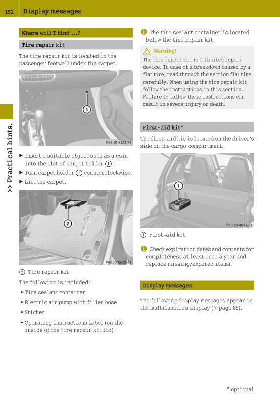
Where will I find ...?
Tire repair kit
The tire repair kit is located in thepassenger footwell under the carpet.
X Insert a suitable object such as a coininto the slot of carpet holder :.
X Turn carpet holder : counterclockwise.
X Lift the carpet.
; Tire repair kit
The following is included:
RTire sealant container
RElectric air pump with filler hose
RSticker
ROperating instructions label (on theinside of the tire repair kit lid)
i The tire sealant container is locatedbelow the tire repair kit.
G Warning!
The tire repair kit is a limited repairdevice. In case of a breakdown caused by aflat tire, read through the section flat tirecarefully. When using the tire repair kitfollow the instructions in this section.Failure to follow these instructions canresult in severe injury or death.
First-aid kit*
The first-aid kit is located on the driver’sside in the cargo compartment.
: First-aid kit
i Check expiration dates and contents forcompleteness at least once a year andreplace missing/expired items.
Display messages
The following display messages appear inthe multifunction display (Y page 88).
152 Display messages>>
Pra
ctic
al h
ints
.
* optional

Display messages Possible causes/consequences and X Solutions
The electronic immobilizer is not working.
X Have the system checked at an authorized smart center.
There is a malfunction in the shifting system.
X Have the system checked at an authorized smart center.
The transmission is taught-in (Y page 87).
X Have the system checked at an authorized smart center.
What to do if ...
Warning and indicator lamps in theinstrument cluster
General information
If any of the following lamps in theinstrument cluster fails to come on during
the bulb self-check when switching onignition (Y page 59), have the respectivebulb checked and replaced if necessary.
Brake
Problem Possible causes/consequences and X Solutions
¬ (USA only)! (Canada only)
The ABS indicatorlamp illuminateswhile the engine isrunning.
There is a malfunction in the ABS system.
X Have the ABS system checked at an authorized smart centerimmediately.
¬ (USA only)! (Canada only)
The ABS indicatorlamp illuminatestogether with thebrake warning lampwhile the engine isrunning.
The ABS system fails.
X Stop the vehicle immediately in a safe location.X Do not continue to drive.
X Turn off the engine.X Engage the parking brake when leaving the vehicle.X Contact Roadside Assistance or an authorized smart center.
What to do if ... 153
>> P
ract
ical
hin
ts.
Z

G Warning!
When the ABS system is malfunctioning, the wheels may lock during hard braking, reducingsteering capability and extending the braking distance.
When the ABS is switched off due to a malfunction, the ESP® is also switched off. The basicdriving and braking functions are still available.
The risk of your vehicle skidding is then increased in certain situations. You shouldtherefore always adapt your speed and driving style to the prevailing road and weatherconditions.
Problem Possible causes/consequences and X Solutions
$ (USA only)J (Canada only)
The brake warninglamp illuminateswhile the engine isrunning.
You are driving with the parking brake engaged.
X Release the parking brake.
The brake circuit fails or the brake fluid level in the brakefluid reservoir is too low.
X Stop the vehicle immediately in a safe location.X Do not continue to drive.
X Turn off the engine.X Do not add brake fluid as this will not solve the problem.X Engage the parking brake when leaving the vehicle.X Contact Roadside Assistance or an authorized smart center.
$ (USA only)J (Canada only)
The brake warninglamp illuminatestogether with the ABSindicator lamp whilethe engine is running.
The ABS system fails.
X Stop the vehicle immediately in a safe location.X Do not continue to drive.
X Turn off the engine.X Engage the parking brake when leaving the vehicle.X Contact Roadside Assistance or an authorized smart center.
G Warning!
Driving with the brake warning lamp illuminated can result in an accident. Have your brakesystem checked immediately if the brake warning lamp stays on.
Do not add brake fluid before checking the brake system.
! If you find that the brake fluid in the brake fluid reservoir has fallen to the minimummark or below, have the brake system checked for brake pad thickness and leaksimmediately. Contact an authorized smart center immediately. Do not add brake fluidas this will not solve the problem.
154 What to do if ...>>
Pra
ctic
al h
ints
.

Safety systems
Problem Possible causes/consequences and X Solutions
7 The seat belttelltaleilluminatesconstantly for amaximum of6 seconds afterstarting theengine.
Regardless of whether the seat belt is fastened or not, the seatbelt telltale always comes on and remains lit for 6 secondsafter starting the engine.
X Fasten your seat belts.
7 The seat belttelltaleilluminatesconstantly. Anadditionalwarning chimesounds for amaximum of6 seconds afterstarting theengine.
The driver’s seat belt is unfastened.
X Fasten your seat belts.
7 The seat belttelltale flasheswithincreasingfrequency of awarning chimefor a maximumof 60 seconds.
The vehicle speed once exceeds 15 mph (25 km/h), and both thedriver’s and passenger seat belt are unfastened.
X Fasten your seat belts.
If the driver’s or the passenger seat belt remains unfastenedafter 60 seconds, the warning chime stops sounding. The seatbelt telltale stops flashing but continues to be illuminated.
The seat belt telltale will only go out if both the driver’s andthe passenger seat belt (with the passenger seat occupied) arefastened, or the vehicle is standing still and a door is opened.
6 Scenario 1:
The SRSindicator lampilluminateswhen theignition isswitched on andgoes out after amaximum of4 seconds.
The subsequent self check of the safety systems detected nomalfunction. The supplemental restraint system isoperational.
What to do if ... 155
>> P
ract
ical
hin
ts.
Z

Problem Possible causes/consequences and X Solutions
6 Scenario 2:
The SRSindicator lampilluminateswhen theignition isswitched on andgoes out after amaximum of4 seconds forapproximately1 second, then itcomes on againand stays on.
There is a malfunction in the supplemental restraint systems.The air bags or Emergency Tensioning Devices could deployunexpectedly or fail to deploy in an accident.
X Do not sit on the passenger seat; this applies particularlyto children.
X Have the system checked at an authorized smart center.
G Warning!
If the SRS indicator lamp does not come on when you switch on the ignition or does not goout again after a few seconds once the engine is running or comes on again, the supplementalrestraint systems are malfunctioning.
In the event that a malfunction of the SRS is indicated as described in scenario 2, the SRSmay not be operational. For your safety, we strongly recommend that you contact anauthorized smart center immediately to have the system checked; A malfunctioning SRSsystem may not deploy when needed in an accident resulting in serious or fatal injury, orit might deploy unexpectedly and unnecessarily which could result in an accident and/orinjury to you or to others.
! If the SRS indicator lamp comes on while driving, have the system checked at anauthorized smart center immediately.
It is possible that the air bag and the emergency tensioning device could be activatedunintentionally or will not function in the event of an accident.
i Information on the operating principle of the air bags can be found in the “Safety”section (Y page 35).
156 What to do if ...>>
Pra
ctic
al h
ints
.

Problem Possible causes/consequences and X Solutions
d The ESP®
warning lampflashes whiledriving.
The ESP® has engaged because of detected traction loss in atleast one tire.
X When driving off, apply as little throttle as possible.X While driving, ease up on the accelerator pedal.X Adapt your speed and driving to the prevailing road and
weather conditions.
d The ESP®
warning lampilluminatescontinuouslywhile theengine isrunning.
The ESP® is not operational due to a system failure.
X Have the system checked at an authorized smart center.
The ESP® is not available.
X Have the system checked at an authorized smart center.
G Warning!
When the ESP® warning lamp is illuminated continuously, the ESP® is not available or notoperational due to a system failure.
Adapt your speed and driving to the prevailing road conditions and the non-operating status
of the ESP®.
i It may be possible to clear a system failure by restarting the engine.
X Restart the engine.If the warning lamp still does not go out, have the system checked at an authorized smartcenter immediately.
i More information on the ESP® can be found in the “Safety” section (Y page 48).
Problem Possible causes/consequences and X Solutions
D The EPS*warning lampilluminateswhile theengine isrunning.
The power steering is not available.
X Have the power steering checked at an authorized smartcenter immediately.
G Warning!
When the power steering is not available a higher degree of effort is necessary to steer thevehicle. Have the system checked at a smart center.
What to do if ... 157
>> P
ract
ical
hin
ts.
* optional Z

Vehicle
Problem Possible causes/consequences and X Solutions
# The batteryindicator lampilluminateswhile drivingor does not goout after theengine isstarted.
The alternator is malfunctioning. The battery is no longercharged.
X Stop the vehicle immediately in a safe location.X Do not continue to drive.
X Turn off the engine.X Engage the parking brake when leaving the vehicle.X Contact Roadside Assistance or an authorized smart center.
The poly-V-belt is broken. The battery is no longer charged.
X Stop the vehicle immediately in a safe location.X Do not continue to drive.
X Turn off the engine.X Engage the parking brake when leaving the vehicle.X Contact Roadside Assistance or an authorized smart center.
! Among other possible causes, the poly-V-belt could be broken. Do not continue todrive. Otherwise, the engine will overheat due to an inoperative water pump which mayresult in damage to the engine.
158 What to do if ...>>
Pra
ctic
al h
ints
.

Problem Possible causes/consequences and X Solutions
K The high‑beamheadlampindicator lampdoes notilluminatewhen thehigh‑beamheadlamps areswitched on orwhen using thehigh‑beamflasher.
The high‑beam headlamp indicator lamp has failed.
X Have the high‑beam headlamp indicator lamp checked at anauthorized smart center.
M The low‑beamheadlampindicator lampdoes notilluminatewhen thelow‑beamheadlamps areswitched on.
The low‑beam headlamp indicator lamp has failed.
X Have the low‑beam headlamp indicator lamp checked at anauthorized smart center.
# !
The turn signalindicator lamp(s)do(es) not illuminatewhen the ignition isswitched on and thecorresponding turnsignal is switched onor the hazard warningflasher is switchedon.
The turn signal indicator lamp(s) has (have) failed.
X Have the turn signal indicator lamp(s) checked at anauthorized smart center.
# !
The turn signalindicator lamp(s)flashes at doublefrequency.
One of the turn signals is malfunctioning.
X Replace the bulb as soon as possible (Y page 169).
orX Have the turn signal checked at an authorized smart center
as soon as possible.
What to do if ... 159
>> P
ract
ical
hin
ts.
Z

Problem Possible causes/consequences and X Solutions
® The fuel capindicator lampcomes on whenthe engine isrunning.
The fuel cap may not be closed properly or the fuel system maybe leaky.
X Check the fuel cap (Y page 110).X If it is not closed properly: Close the fuel cap.
X If it is closed properly: Have the fuel system checked at anauthorized smart center.
Engine
Problem Possible causes/consequences and X Solutions
? The coolanttemperaturewarning lampilluminateswhile theengine isrunning.
The coolant is too hot.
X Stop the vehicle immediately in a safe location.X Do not continue to drive.
X Turn off the engine.X Engage the parking brake when leaving the vehicle.X Contact Roadside Assistance or an authorized smart center.
The coolant level has fallen below the marking bar on thecoolant reservoir (Y page 115).
X Add coolant as required.X Have the coolant system checked for leaks at an authorized
smart center.
G Warning!
Driving when your engine is overheated can cause some fluids, which may have leaked intothe engine compartment, to catch fire. You could be seriously burned.
Turn off the engine, get out of the vehicle and do not stand near the vehicle until the enginehas cooled down.
! Among other possible causes, the poly-V-belt could be broken. Do not continue todrive. Otherwise, the engine will overheat due to an inoperative water pump which mayresult in damage to the engine.
Problem Possible causes/consequences and X Solutions
; The enginemalfunctionindicator lampilluminateswhile driving.
There is a malfunction in the system.
X Have the vehicle checked at an authorized smart centerimmediately.
160 What to do if ...>>
Pra
ctic
al h
ints
.

i Some states may by law require you to visit a workshop as soon as the enginemalfunction indicator lamp comes on. Check local requirements.
Problem Possible causes/consequences and X Solutions
5 The engine oilpressureindicator lampilluminateswhile driving.
The engine oil pressure is low.
X Stop the vehicle immediately in a safe location.X Do not continue to drive.
X Turn off the engine.X Engage the parking brake when leaving the vehicle.X Contact Roadside Assistance or an authorized smart center.
5 The engine oilpressureindicator lampgoes out beforethe enginestarts.
The engine oil pressure indicator lamp has failed.
X Check the engine oil level.X Have the system checked at an authorized smart center.
! The engine oil pressure indicator lamp should not be ignored. Extended driving withthe engine oil pressure indicator lamp illuminated could result in serious enginedamage that is not covered by the smart Limited Warranty.
What to do if ... 161
>> P
ract
ical
hin
ts.
Z

Tires
Problem Possible causes/consequences and X Solutions
h Thecombinationlow tirepressure/TPMSmalfunctiontelltaleilluminatescontinuously.
The TPMS detects a loss of pressure in at least one tire.
X Carefully bring the vehicle to a halt, avoiding abruptsteering and braking maneuvers. Observe the trafficsituation around you.
X Check and correct tire inflation pressure as required(Y page 120).
If the tire inflation pressure in the respective tire(s) has(have) been corrected, the combination low tire pressure/TPMSmalfunction telltale goes out after a few minutes of driving.See also “Restarting the TPMS” .
h Thecombinationlow tirepressure/TPMSmalfunctiontelltale flashes60 seconds andthen staysilluminated.
There is a malfunction in the TPMS.
X Have the TPMS checked at an authorized smart center.
After the malfunction has been remedied the combination lowtire pressure/TPMS malfunction telltale goes out after a fewminutes of driving.
G Warning!
Each tire should be checked monthly when cold and inflated to the inflation pressurerecommended by the vehicle manufacturer on the Tire and Loading Information placard. Ifyour vehicle has tires of a different size than the size indicated on the Tire and LoadingInformation placard, you should determine the proper tire inflation pressure for thosetires.
As an added safety feature, your vehicle has been equipped with a tire pressure monitoringsystem (TPMS) that illuminates a low tire pressure telltale when one or more of your tiresis significantly underinflated.
Accordingly, when the low tire pressure telltale illuminates, you should stop and check yourtires as soon as possible, and inflate them to the proper pressure. Driving on a significantlyunderinflated tire causes the tire to overheat and can lead to tire failure.
Underinflation also reduces fuel efficiency and tire tread life, and may affect the vehicle’shandling and stopping ability. Please note that the TPMS is not a substitute for proper tiremaintenance, and it is the driver’s responsibility to maintain correct tire pressure, evenif underinflation has not reached the level to trigger illumination of the TPMS low tirepressure telltale.
Your vehicle has also been equipped with a TPMS malfunction indicator to indicate whenthe system is not operating properly. The TPMS malfunction indicator is combined with thelow tire pressure telltale. When the system detects a malfunction, the telltale will flash forapproximately 1 minute and then remain continuously illuminated.
162 What to do if ...>>
Pra
ctic
al h
ints
.

This sequence will continue upon subsequent vehicle start-ups as long as the malfunctionexists. When the malfunction indicator is illuminated, the system may not be able to detector signal low tire pressure as intended.
TPMS malfunctions may occur for a variety of reasons, including the installation ofincompatible replacement or alternate tires or wheels on the vehicle that prevent the TPMSfrom functioning properly. Always check the TPMS malfunction telltale after replacing oneor more tires or wheels on your vehicle to ensure that the replacement or alternate tiresand wheels allow the TPMS to continue to function properly.
Warning and indicator lamps in the overhead control panel
Problem Possible causes/consequences and X Solutions
4 0
The passenger frontair bag off indicatorlamp illuminates andremains illuminatedwith the weight of atypical adult orsomeone larger than asmall individual onthe passenger seat.
There is a malfunction in the system.
X Have the system checked at an authorized smart center.
4 0
The passenger frontair bag off indicatorlamp does notilluminate or remainsout with the weight ofa typical12‑month‑old child ina standard childrestraint or less onthe passenger seat
There is a malfunction in the system.
X Have the system checked at an authorized smart center.
G Warning!
If the 40 indicator lamp illuminates and remains illuminated with the weightof a typical adult or someone larger than a small individual on the passenger seat, do nothave any passenger use the passenger seat until the system has been repaired.
G Warning!
If the 40 indicator lamp does not illuminate or remains out with the weight ofa typical 12‑month‑old child in a standard child restraint or less on the passenger seat, donot transport a child on the passenger seat until the system has been repaired.
What to do if ... 163
>> P
ract
ical
hin
ts.
Z

Engine
Problem Possible causes/consequences and X Solutions
The engine does notstart.
X Check ifRthe gear selector lever is in park position P
Rthe brake pedal has been depressed
Rthe transmission position indicator is on P or N
The engine does notstart within4 seconds.
X Wait for a few seconds.X Repeat the starting procedure.
Remember that extended starting attempts can drain thevehicle battery.
The engine does notstart after severalstarting attempts.
X Engage the parking brake when leaving the vehicle.X Contact Roadside Assistance or an authorized smart center.
Loss of key
Problem Possible causes/consequences and X Solutions
You lose a key. X Have the key deactivated at an authorized smart center.X Report the loss of the key to your car insurance company
immediately.X If necessary, have the mechanical lock replaced.
Your authorized smart center will be glad to supply you with areplacement following an identity check.
164 What to do if ...>>
Pra
ctic
al h
ints
.

Acoustic warning signals
Problem Possible causes/consequences and X Solutions
Once the anti-theftwarning system* hasbeen armed, a visualand audible alarm istriggered.
The alarm is triggered whenRsomeone opens a door or the tailgate
Rthe driver’s door is unlocked with the key (Y page 166)
Rthe vehicle’s interior is entered
Rthere is motion inside the vehicle
Rthe vehicle is raised
To cancel the alarm:
X Insert the key in the starter switch.X Turn the key to starter switch position 1.
orX Press button # or * on the key.
A warning signalsounds.
The door is opened while a gear is engaged with the enginerunning and neither the brake nor accelerator pedals aredepressed.
X Close the driver’s and passenger door.X Move the gear selector lever to park position P.
orX Turn off the engine.
You open the driver’s door with the key in starter switchposition 0.
X Close the driver’s door.
orX Remove the key from the starter switch.
A warning signalsounds.
The seat belts are not fastened when the engine is started. Fordetails, see seat belt telltale (Y page 155).
X Fasten your seat belts.
You can hear acontinuous noise fromthe front axle whenbraking.
The vehicle is equipped with a mechanical/acoustic brake padindicator.
X Have the brake pads checked at an authorized smart center.
What to do if ... 165
>> P
ract
ical
hin
ts.
* optional Z

Unlocking/locking manually
Unlocking the vehicle
You can unlock the driver’s door and thefuel filler flap by unlocking the driver’sdoor using the key. The lock cylinder isfitted with a cap.
X Press button # on the key.
The anti-theft warning system* isdisarmed.
i If the transmitter battery in the key isdischarged, the anti-theft warningsystem* can no longer be disarmed withbutton # on the key. For replacing thetransmitter battery (Y page 167).
Unlocking the vehicle with the key andopening a door or the tailgate willtrigger the anti-theft warning system*(Y page 49).
To cancel the alarm:
X Insert the key in the starter switch.X Turn the key to starter switch position
1.
X Remove cap : from lock cylinder ;.
X Unlock the driver’s door.The driver’s door and the fuel filler flapare unlocked.
i To unlock the vehicle centrally pressthe central unlocking switch in the uppercenter console (Y page 28).
Locking the vehicle
If you can no longer lock the vehicle usingthe remote control and you do not have aspare transmitter battery at hand, pleaseproceed as follows:
X Open the driver’s door.X Press the central locking switch
(Y page 56).The indicator lamp on the centrallocking switch comes on, when the starterswitch is in position 1.
The indicator lamp on the centrallocking switch flashes, when the starterswitch is in position 0.
X Remove the key from the starter switch,take it with you, and close all doors.The vehicle is now locked and the anti-theft warning system* is armed.
Closing the rear soft top
If the rear soft top does not lock properlyafter being closed, proceed as follows:
X Stop the vehicle in a safe location.X Engage the parking brake.X Make sure the key is in starter switch
position 1.
X Fold up the rear soft top completely.The rear soft top stops in the unlockedposition.
X Within one minute, press and hold symbolG on the retractable soft top switchfor 15 seconds twice.The rear soft top closes the lockinghooks.
X Close the retractable soft topcompletely.
X Have the rear soft top checked at anauthorized smart center.
166 Unlocking/locking manually>>
Pra
ctic
al h
ints
.
* optional

Replacing transmitter battery
Notes
The remote control’s transmitter battery isalmost spent when the turn signals flashrapidly nine times in a row when lockingthe vehicle.
i If you do not replace the transmitterbattery, after about 100 more times youwill no longer be able to lock or unlockthe vehicle using the remote control.
X Replace the transmitter battery.
orX Have the transmitter battery replaced at
an smart center.
G Warning!
Batteries contain poisonous and corrosivesubstances. Therefore keep the batteriesout of reach of children.
If a battery is swallowed, seek medical helpimmediately.
Batteries contain materials that can harmthe environment if disposed of improperly.Recycling of batteries is the preferredmethod of disposal. Many states/provincesrequire sellers of batteries to accept oldbatteries for recycling.
Replacing battery
Replacement battery: CR 2016 button cell
! Replace the remote control’stransmitter battery every two years atthe latest. Otherwise there is a danger ofleakage. The remote control could bedamaged.
X Insert a suitable object such as a coininto the slot at the eyelet of the keyhousing.
X Carefully turn the coin until key housingtop half : is unlatched.
X Open key housing top half : to the side.
X Remove transmitter battery ; from theboard.
! Check the polarity when inserting thenew transmitter battery. You couldotherwise damage parts of the electricalsystem. When inserting the batteries,make sure they are clean and free of lint.
X Insert the new transmitter battery.X Press both halves of the key housing
together again.X Check the operation of the remote
control.
Replacing transmitter battery 167
>> P
ract
ical
hin
ts.
Z

Replacing bulbs
About replacing bulbs
Safe vehicle operation depends on properexterior lighting and signaling. It istherefore essential that all bulbs and lampassemblies are in good working order at alltimes.
Correct headlamp adjustment is extremelyimportant. Have headlamps checked andreadjusted at regular intervals and when abulb has been replaced. Contact anauthorized smart center for headlampadjustment.
G Warning!
Bulbs and bulb sockets can be very hot.Allow the lamp to cool down before changinga bulb. Otherwise you could be burned if youtouch them.
Keep bulbs out of the reach of children.
Halogen lamps contain pressurized gas. Abulb can explode if you:
Rtouch or move it when hot
Rdrop the bulb
Rscratch the bulb
Wear eye and hand protection.
i If the headlamps or front fog lamps* arefogged up on the inside as a result ofhigh humidity, driving the vehicle adistance with the lights on should clearup the fogging.
Notes on bulb replacement:
ROnly use bulbs of the same type and withthe specified watt rating.
RSwitch the lights off before replacing abulb to prevent short circuits.
RAlways use a clean lint-free cloth whenhandling bulbs.
RYour hands should be dry and free of oiland grease.
RAvoid touching the glass of the bulb withbare fingers.
RIf the newly installed bulb does not comeon, contact an authorized smart center.
RHave the bulbs for the front fog lamps*replaced at an authorized smart center.
168 Replacing bulbs>>
Pra
ctic
al h
ints
.
* optional

Overview bulbs
Front lamps
Headlamp Type
: Parking and side marker lamp
WY 5 W; Turn signal lamp
2357 A= Low‑beam headlamp
H7 (55 W)? High‑beam headlamp
H7 (55 W)
Front fog lamp* Type
: Front fog lamp
H 11
Side turn signal lamp Type
: Side turn signal lamp
WY 5 W
Replacing bulbs 169
>> P
ract
ical
hin
ts.
* optional Z

Rear lamps
Tail lamp unit Type
: Brake lamp/tail lamp/turn signallamp/side marker lamp
12 V 21/5 W; Reflector
-= Backup lamp
12 V 21 W
License plate lamps Type
: License plate lamps
C 5 W
High‑mounted brake lamp Type
: High‑mounted brake lamp
W 16 W
170 Replacing bulbs>>
Pra
ctic
al h
ints
.

Replacing bulbs for front lamps
Before you start to replace a bulb for afront lamp, do the following first:
X Turn the exterior lamp switch to position$ (Y page 66).
X Switch off the ignition.X Open the service flap (Y page 114).
Left headlamp, (right headlamp in reverse)
: Bulb socket for parking, and sidemarker lamp
; Bulb socket for turn signal lamp
= Low‑beam headlamp cover
? High‑beam headlamp cover
Parking and side marker lamp bulb
X Removing:
Driver’s side: Turn bulb socket : towardthe outside.
Passenger side: Turn bulb socket :toward the outside.
X Pull bulb socket : out of the headlamphousing.
X Pull the bulb out of bulb socket :.
X Installing: Insert the new bulb into bulbsocket :.
X Insert bulb socket : into the headlamphousing.
X Driver side: Turn bulb socket : towardthe inside.
Passenger side: Turn bulb socket :toward the inside.
Low‑beam headlamp bulb
X Removing: Take off low‑beam headlampcover =.
X Detach the electrical connector.X Bend the retainer spring end down and
forward until it unclips. Fold theretainer spring back.
X Pull the bulb out of the headlamphousing.
X Installing: Insert the new bulb into theheadlamp housing.
X Fold the retainer spring forward.
Bend the retainer spring end forwardthen up and back to clip in.
X Attach the electrical connector.X Reinstall low‑beam headlamp cover =.
High‑beam headlamp bulb
X Removing: Take off high‑beam headlampcover ?.
X Detach the electrical connector.X Tilt the bulb socket down and pull it out.X Pull the bulb out of the bulb socket.
X Installing: Insert the new bulb into thebulb socket.
X Fit the bulb so that the retaining lug ofthe base plate is pointing up.
X Press the bulb into the bulb socket untilit is fully engaged.
X Attach the electrical connector.X Reinstall high‑beam headlamp
cover ?.
Replacing bulbs 171
>> P
ract
ical
hin
ts.
Z

Front turn signal lamp bulb
X Removing: Turn bulb socket ;counterclockwise by a quarter of turn andpull it out of the headlamp housing.
X Press gently onto the bulb and turn itcounterclockwise.
X Pull the bulb out of bulb socket ;.
X Installing: Insert the new bulb into bulbsocket ;.
X Press gently onto the bulb and turn itclockwise.
X Insert bulb socket ; into the headlamphousing.
The arrow on bulb socket ; must be inline with the line on the headlamphousing.
X Turn bulb socket ; clockwise by aquarter of turn.
Side turn signal lamp bulb
X Removing: Open the door on thecorresponding side.
X Press on retaining lug : in thedirection of the arrow until the side turnsignal lamp housing disengages.
X Use a suitable tool to loosen the side turnsignal lamp housing from the fender.
X Turn the bulb socket counterclockwiseand pull it out of the side turn signallamp housing.
X Pull the bulb out of the bulb socket.
X Installing: Insert the new bulb into thebulb socket.
X Insert the bulb socket into the side turnsignal lamp housing and turn the bulbsocket clockwise.
X Fit the side turn signal lamp housingonto the fender.
X Press gently onto the side turn signallamp housing.
The side turn signal lamp housing mustaudibly engage.
Replacing bulbs for rear lamps
Before you start to replace a bulb for a rearlamp, do the following first:
X Turn exterior lamp switch to position$ (Y page 66).
X Switch off the ignition.
Tail lamp unit
X Removing:
Coupé: Open the upper tailgate.X Open the lower tailgate.X Cabriolet: Open the rear soft top
(Y page 75).X Remove the side cover in the cargo
compartment on the corresponding side.X Fold the damping material forward, if
necessary.
172 Replacing bulbs>>
Pra
ctic
al h
ints
.

Left bulb carrier illustrated as example
: Retaining tab
; Electrical connector
X Press retaining tab : in the center ofthe bulb carrier upwards.
X Pull the bulb carrier out of the tail lamphousing.
Left bulb carrier with bulb sockets (right bulbcarrier in reverse)
: Retaining tab
= Brake, tail, turn signal and side markerlamp bulb
? Backup lamp bulb
X Depending on which bulb needs to bereplaced, press gently onto bulb =or ? and turn it counterclockwise.
X Pull the bulb out of the bulb socket.
X Installing: Insert the new bulb into thebulb socket.
X Press gently onto the bulb and turn itclockwise until it engages.
X Insert the bulb carrier into the tail lamphousing.
X Press gently onto the bulb carrier.
Let retaining tab : engage.
X Fold the damping material backward, ifnecessary.
X Reinstall the side cover in the cargocompartment.
High mounted brake lamp
X Removing: Unscrew retaining screws :.
X Remove high mounted brake lamp ;.
X Detach electrical connector ? from bulbsocket =.
X Turn the bulb counterclockwise and pullit out of its socket.
X Installing: Install in the reverse order.
License plate lamps
G Warning!
High outside temperature, stop-and-gotraffic, driving on long uphill grades, ordriving at high engine speed may increasethe temperature in the enginecompartment. Therefore the area around theair slots in the rear apron may be hot. Letthe engine cool off before touching thisarea to prevent burns.
Replacing bulbs 173
>> P
ract
ical
hin
ts.
Z

X Use a suitable tool to loosen thecorresponding license plate lamp unit atjacking point :.
X Carefully unclip the license plate lampunit.
X Detach electrical connectors ;.
X Remove bulb =.
X Insert the new bulb.X Attach electrical connectors ;.
X Fit the license plate lamp unit on theright and press gently on the left.
The license plate lamp unit must audiblyengage.
Replacing the interior lighting
You need a 12 V 10 W bulb.
X Removing: Use a flat object to pry thelamp lens off from the passenger side.
X Detach electrical connector : from theinterior lamp.
X Remove bulb ; from its mount =.
X Installing: Insert the new bulb.
X Attach electrical connector : to theinterior lamp.
X Fit the lamp lens on the left in theopening and press gently on the right.
The lamp lens must audibly engage.
Replacing wiper blades
About replacing wiper blades
G Warning!
For safety reasons, switch off the wipersand remove the key from the starter switchbefore replacing a wiper blade. Thewindshield wipers could otherwise be setin motion and cause injury.
G Warning!
Wiper blades are components that aresubject to wear and tear. Replace the wiperblades at least twice a year, preferably inthe spring and fall. Otherwise the windowswill not be properly wiped. As a result, youmay not be able to observe surroundingtraffic conditions and could cause anaccident.
174 Replacing wiper blades>>
Pra
ctic
al h
ints
.

! Hold on to the wiper when folding thewiper arm back. If released, the force ofthe impact from the windshield wipertensioning spring could crack thewindshield.
Do not allow the wiper arms to contact thewindshield glass without a wiper bladeinserted.
We recommend that you have this workcarried out at an authorized smartcenter.
To ensure proper visibility
Rit is vital that you have wiper blades thatare in perfect shape
Rclean the wiper blades regularly with acleaning agent
Rremove any tough dirt stains with asponge or brush
Windshield wiper blades
! Do not pull on the wiper blade inserts.They could tear.
X Remove the key from the starter switch.
X Fold wiper arm ? away from thewindshield until it snaps into place.
X Removing: Press on retainingsprings ; on both sides of wiperblade :.
X Fold wiper blade : away from wiperarm ? in the direction of arrow =.
X Detach wiper blade : in the directionof arrow A.
X Installing: With guide tab A slidinginto opening B, attach new wiperblade : onto the wiper arm.
X Fold wiper blade : towards the wiperarm in the direction of arrow =.Retaining springs ; must audiblyengage in attachment ?.
X Check wether wiper blade : is securelyfastened.
X Fold the wiper arm backward to rest onthe windshield.Make sure to hold on to the wiper whenfolding it back.
! Make sure the wiper blades are properlyinstalled. Improperly installed wiperblades may cause windshield damage.
Replacing wiper blades 175
>> P
ract
ical
hin
ts.
Z

Rear window wiper blade
X Removing: Fold the wiper arm away fromthe rear window until you feel it engage.
X Fold wiper blade : away from the wiperarm in the direction of arrow ; until itdisengages from its mounting.
X Detach wiper blade :.
X Installing: Push the new wiper blade ontothe wiper arm until you feel it engage.
X Fold the wiper blade into a positionparallel to the wiper arm.
X Fold the wiper arm backward to rest onthe rear window.
Make sure to hold on to the wiper whenfolding the wiper arm back.
! Make sure the wiper blade is properlyinstalled. An improperly installedwiper blade may cause rear windowdamage.
Adjusting the washer jet nozzles
: Front washer jet nozzles
; Rear washer jet nozzles
X Adjusting: Use a needle to move washerjet nozzles : or ; left, right, up, ordown.
i Check the setting of the washer jetnozzles at regular intervals. The washerjet nozzles are correctly set when thewater jet hits the windshield or the rearwindow approximately in the center.
Flat tire
Preparing the vehicle
Upon experiencing any type of problemwith the vehicle’s tires, switch on thehazard warning flasher, carefully slowdown and exit the roadway in a cautiousmanner.
X Park the vehicle at a safe distance frommoving traffic on a hard, flat surfacewhen possible.
X Make sure the tire valve of the damagedtire is located below the horizontal axleof the wheel hub.
X Engage the parking brake.X Turn the steering wheel so that the front
wheels are in a straight ahead position.X Move the gear selector lever to park
position P.
X Turn off the engine.
176 Flat tire>>
Pra
ctic
al h
ints
.
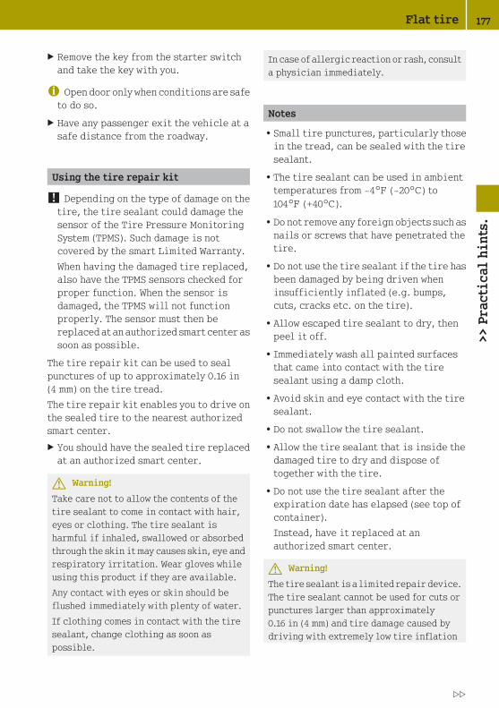
X Remove the key from the starter switchand take the key with you.
i Open door only when conditions are safeto do so.
X Have any passenger exit the vehicle at asafe distance from the roadway.
Using the tire repair kit
! Depending on the type of damage on thetire, the tire sealant could damage thesensor of the Tire Pressure MonitoringSystem (TPMS). Such damage is notcovered by the smart Limited Warranty.
When having the damaged tire replaced,also have the TPMS sensors checked forproper function. When the sensor isdamaged, the TPMS will not functionproperly. The sensor must then bereplaced at an authorized smart center assoon as possible.
The tire repair kit can be used to sealpunctures of up to approximately 0.16 in(4 mm) on the tire tread.
The tire repair kit enables you to drive onthe sealed tire to the nearest authorizedsmart center.
X You should have the sealed tire replacedat an authorized smart center.
G Warning!
Take care not to allow the contents of thetire sealant to come in contact with hair,eyes or clothing. The tire sealant isharmful if inhaled, swallowed or absorbedthrough the skin it may causes skin, eye andrespiratory irritation. Wear gloves whileusing this product if they are available.
Any contact with eyes or skin should beflushed immediately with plenty of water.
If clothing comes in contact with the tiresealant, change clothing as soon aspossible.
In case of allergic reaction or rash, consulta physician immediately.
Notes
RSmall tire punctures, particularly thosein the tread, can be sealed with the tiresealant.
RThe tire sealant can be used in ambienttemperatures from ‑4¦ (‑20¥) to104¦ (+40¥).
RDo not remove any foreign objects such asnails or screws that have penetrated thetire.
RDo not use the tire sealant if the tire hasbeen damaged by being driven wheninsufficiently inflated (e.g. bumps,cuts, cracks etc. on the tire).
RAllow escaped tire sealant to dry, thenpeel it off.
RImmediately wash all painted surfacesthat came into contact with the tiresealant using a damp cloth.
RAvoid skin and eye contact with the tiresealant.
RDo not swallow the tire sealant.
RAllow the tire sealant that is inside thedamaged tire to dry and dispose oftogether with the tire.
RDo not use the tire sealant after theexpiration date has elapsed (see top ofcontainer).
Instead, have it replaced at anauthorized smart center.
G Warning!
The tire sealant is a limited repair device.The tire sealant cannot be used for cuts orpunctures larger than approximately0.16 in (4 mm) and tire damage caused bydriving with extremely low tire inflation
Flat tire 177
>> P
ract
ical
hin
ts.
Z

pressure, or on a flat tire, or a damagedwheel.
Do not drive the vehicle under suchcircumstances.
If you are unsure of the condition of the tireor have any question whatsoever about itssuitability for driving contact the nearestsmart center for assistance or callRoadside Assistance.
G Warning!
Please review the instructions below forusing the tire repair kit. If you are notconfident that you can competently followthe instructions for using this kit, do notuse the kit, but instead call for RoadsideAssistance.
G Warning!
Keep the tire sealant out of reach ofchildren. If swallowed, rinse mouthimmediately with plenty of water and drinkplenty of water.
Do not induce vomiting!
Consult a physician immediately.
Keep away from open flame, heat source orsparks. Do not smoke.
Sealing a tire
X Take the tire repair kit from thepassenger footwell (Y page 152).
X Open the tire repair kit lid.
: Flange lid
; Pressure gauge
= Vent screw
? Filler hose with stopper
A Operating instructions label
B Electrical plug
C Electric air pump switch
D Sticker
E Tire sealant container
X Remove sticker D from the tire repairkit.
X Attach sticker D where it will be easilyseen by the driver on the instrumentcluster.
G Warning!
Follow safety instructions on the electricair pump label.
X Unwind electrical plug B and fillerhose ?.
: Flange lid
178 Flat tire>>
Pra
ctic
al h
ints
.

X Unscrew flange lid :.
X Unscrew the lid of tire sealant containerE. Make sure not to damage the aluminumseal.
E Tire sealant container
F Flange
X Screw tire sealant container E ontoflange F.
Make sure the container is threadedcorrectly onto the flange. This puncturesthe aluminum seal of the tire sealantcontainer.
X Unscrew the valve cap from the tire valveof the damaged tire.
X Close vent screw =.
X Pull off the stopper of filler hose ?.
? Filler hose
G Tire valve
X Screw the end of filler hose ? onto tirevalve G.
X Insert electrical plug B into theauxiliary power outlet (Y page 107).
X Insert the key in the starter switch andturn it to position 1.
i The vehicle’s battery is drained by useof the electric air pump. You shouldtherefore keep the engine running — inthe open air — while inflating the tire.
C Electric air pump switch
X Press I on electric air pump switch C.The electric air pump is switched on andinflates the tire.
i First, the sealant is pumped into thetire. The pressure may briefly increaseto a high value. This is normal and not anindication of a malfunction. Do notswitch off the electric air pump.
X Let the electric air pump inflate the tirefor a maximum of ten minutes.
Pressure gauge ; must display at least26 psi (1.8 bar).
G Warning!
The filler hose can become hot duringinflation.
Please exercise appropriate caution.
! Do not operate the electric air pumplonger than ten minutes withoutinterruption. Otherwise it may overheat.
Flat tire 179
>> P
ract
ical
hin
ts.
Z

You may operate the electrical air pumpagain after it has cooled off.
X If a tire inflation pressure of at least26 psi (1.8 bar) is not attained, turn offthe electric air pump by pressing 0 onelectric air pump switch C.
X Unscrew the end of filler hose ? fromtire valve G.
X After clearing the area around thevehicle of people and obstacles, drivevehicle back or forth very slowlyapproximately 30 ft (10 m).
This serves to better distribute the tiresealant material inside the tire.
X Screw the end of filler hose ? onto tirevalve G.
X Inflate the tire again.
G Warning!
If a tire inflation pressure of 26 psi(1.8 bar) is not attained, the tire is tooseverely damaged for the tire sealant toprovide a reliable tire repair.
In this case, the tire sealant cannotproperly seal the tire.
Do not drive the vehicle.
Contact the nearest smart center forassistance or call Roadside Assistance.
X After attaining a tire inflation pressureof at least 26 psi (1.8 bar), press 0 onelectric air pump switch C.The electric air pump is switched off.
X Turn the key in the starter switch toposition 0.
X Unscrew the end of filler hose ? fromtire valve G.
G Warning!
The filler hose may still be hot.
Please exercise appropriate caution.
X Plug filler hose with the stopper.X Tire sealant container E remains
screwed onto flange F.
X Place the tire repair kit securely in thevehicle.
X Drive off immediately.The tire sealant will distribute itselfevenly inside the tire.
G Warning!
Do not exceed vehicle speed of 50 mph(80 km/h). A tire sealant repair is notdesigned to operate at higher speeds.
The sticker must be attached on theinstrument cluster where it will be easilyseen by the driver.
Vehicle handling characteristics of a tiresealant repaired tire may change. Adaptyour driving accordingly.
X After driving for about 1.8 miles (3 km)or ten minutes, take all of theappropriate safety precautions and thentake the tire repair kit from the vehicle.
X Screw the end of filler hose ? onto tirevalve G.
X Check the tire inflation pressure usingpressure gauge ;.
G Warning!
If tire inflation pressure has fallen below20 psi (1.3 bar) do not continue to drive thevehicle.
Park your vehicle safely away from theroadway and contact the nearest smartcenter or call Roadside Assistance.
Have the damaged tire replaced.
X If the tire inflation pressure is at least20 psi (1.3 bar), inflate or deflate thetire to correct tire inflation pressure(see Tire and Loading Informationplacard located on the driver’s doorB‑pillar).
180 Flat tire>>
Pra
ctic
al h
ints
.

RTo increase the tire inflationpressure: Switch on the electric airpump.
RTo decrease the tire inflationpressure: Open vent screw =. Recheckthe tire inflation pressure with theelectric air pump’s pressure gauge.
X After checking the tire inflationpressure, unscrew the end of fillerhose ? from tire valve G.
X Plug filler hose with the stopper.X Place the tire repair kit securely in the
vehicle.X Screw the valve cap onto the tire valve.
! The manufacturer is unable toguarantee that all tire punctures can berepaired with the tire repair kit, inparticular cuts or perforations largerthan approximately 0.16 in (4 mm) or awayfrom the tire’s tread. The manufactureris not liable for damage sustainedthrough improper use of the tire repairkit.
G Warning!
Follow recommended tire inflationpressures.
Do not underinflate tires. Underinflatedtires wear excessively and/or unevenly,adversely affect handling and fueleconomy, and are more likely to fail frombeing overheated.
Do not overinflate tires. Overinflatedtires can adversely affect handling andride comfort, wear unevenly, increasestopping distance, and result in suddendeflation (blowout) because they are morelikely to become punctured or damaged byroad debris, potholes etc.
Do not overload the tires by exceeding thespecified load limit as indicated on theTire and Loading Information placard onthe driver’s door B‑pillar. Overloading thetires can overheat them, possibly causinga blowout. Overloading the tires can also
result in handling or steering problems, orbrake failure.
X Drive to the nearest authorized smartcenter, to have the damaged tirereplaced.
X Contact an authorized smart center assoon as possible to obtain a new fillerhose and a new tire sealant container.
X Bring used tire sealant materials to anauthorized smart center for properdisposal.
X Replace your tire sealant containerevery 4 years. Replacement containersare available at any authorized smartcenter.
G Warning!
After changing a tire, contact a smartcenter to make sure the bolts holding thewheel to the car are tight enough.Otherwise, the wheels could come off. Eachbolt should be tightened to a torque of81 lb‑ft (110 Nm).
Wheel change
Preparing the vehicle
X Park the vehicle on a hard, flat surfacewhen possible.
X Turn on the hazard warning flasher.X Turn the steering wheel so that the front
wheels are in a straight-ahead position.X Engage the parking brake.X Move the gear selector lever to park
position P.
X Turn off the engine.X Have any passenger exit the vehicle at a
safe distance from the roadway.
Wheel change 181
>> P
ract
ical
hin
ts.
Z

Removing the wheel
G Warning!
When jacking up the vehicle, only use asuitable jack. Observe the manufacturer’ssafety instructions.
The jack must be designed for jacking upthis vehicle at the jack take-up bracketsbuilt into both sides of the vehicle.
The jack is intended only for lifting thevehicle briefly for wheel changes. It is notsuited for performing maintenance workunder the vehicle. To help avoid personalinjury, use the jack only to lift the vehicleduring a wheel change.
Never get beneath the vehicle while it issupported by the jack. Keep hands and feetaway from the area under the lifted vehicle.Always lower the vehicle onto sufficientcapacity jackstands before working underthe vehicle.
Always firmly engage the parking brake andblock the wheels with wheel chocks or othersizeable objects before raising thevehicle with the jack. Do not release theparking brake while the vehicle is raised.
Make sure the ground on which the vehicleis standing and where you place the jack issolid, level and not slippery. If necessary,use a large underlay. On slippery surfaces,such as tiled floors, you should use a non-slip underlay, for example a rubber mat.
Do not use wooden blocks or similar objectsto support the jack. Otherwise the jack maynot be able to achieve its load-bearingcapacity if it is not at its full height.
The jack must always be vertical when inuse. Always try to use the jack on levelsurface. If you do not position the jackcorrectly, the vehicle can fall off the jackand seriously or fatally injure you orothers.
Never start the engine when the vehicle israised.
Also observe the notes on the jack.
X Make sure to have a suitable jack17 andwheel wrench17.
Contact an authorized smart center forinformation on which jack and wheelwrench are required.
X Prepare the vehicle as described(Y page 181).
X Make sure the surface is level.
Prevent the vehicle from rolling away byblocking wheels with wheel chocks (notincluded) or other sizeable objects:
X Place one wheel chock or other sizeableobject in front of and another wheelchock or other sizeable object behindthe wheel that is diagonally opposite tothe wheel being changed.
Steel rim with wheel cover
X Vehicles with wheel cover on steel rim:Pull the wheel cover off of the rim.
If necessary, use a suitable tool to prythe wheel cover off.
X On wheel to be changed, loosen but do notyet remove the wheel bolts(approximately one full turn with wheelwrench).
17 Not included and not available as factory equipment.
182 Wheel change>>
Pra
ctic
al h
ints
.

Steel rim with wheel trim cap
X Vehicles with wheel trim cap on steelrim: On wheel to be changed, loosen butdo not yet remove the wheel bolts(approximately one full turn with wheelwrench).
X Take the wheel trim cap off.
X Position jack : under take-upbracket ; so that it is always verticalas seen from the side, even if the vehicleis parked on an incline.
The take-up brackets are identified bythe embossed recesses in the area of thedoor sills.
! Only position the jack on thedesignated take-up brackets. Otherwise,the vehicle could be damaged.
X Jack up the vehicle until the wheel is amaximum of 1.2 in (3 cm) from the ground.
X Unscrew and remove the wheel bolts.
! Do not place wheel bolts in sand or dirt.This could result in damage to the wheelbolts and wheel hub threads.
X Remove the wheel.
Mounting the wheel
G Warning!
Always replace wheel bolts that aredamaged or rusted.
Never apply oil or grease to wheel bolts.
Damaged wheel hub threads should berepaired immediately. Do not continue todrive under these circumstances! Contactan authorized smart Center or callRoadside Assistance.
Incorrect wheel bolts or improperlytightened wheel bolts can cause the wheelto come off. This could cause an accident.Be sure to use the correct wheel bolts.
G Warning!
Only use genuine smart wheel bolts. Otherwheel bolts may come loose.
Do not tighten the wheel bolts when thevehicle is raised. Otherwise the vehiclecould fall off the jack.
X Clean contact surfaces of wheel and wheelhub.
! To avoid paint damage, place wheel flatagainst hub and hold it there whileinstalling first wheel bolt.
Wheel change 183
>> P
ract
ical
hin
ts.
Z

X Guide the wheel onto the wheel hub andpush it on.
X Insert two wheel bolts and tighten themslightly.
X Vehicles with wheel trim cap on steelrim: Attach the wheel trim cap so that itis held by the two wheel bolts.
X Install last wheel bolt and tighten itslightly.
X Lower the vehicle until the vehicle isresting fully on its own weight.
X Remove the jack.X Tighten the wheel bolts. Observe a
tightening torque of 80 lb-ft (110 Nm).
G Warning!
Have the tightening torque checked afterchanging a wheel. The wheels could comeloose if they are not tightened to a torqueof 80 lb-ft (110 Nm).
Steel rim with wheel cover
X Vehicles with wheel cover on steel rim:Position wheel cover aperture : sovalve ; fits through.
X Push the wheel cover evenly onto thewheel rim with both hands.
X Check that the wheel cover is fixedsecurely to the wheel rim.
i The Tire Pressure Monitoring System(TPMS) only functions on wheels that are
equipped with the proper electronicsensors (Y page 121).
Battery
About the battery
Your vehicle’s battery is located in thepassenger footwell below the footrest(Y page 186).
The battery should always be sufficientlycharged in order to achieve its ratedservice life. Refer to Maintenance Bookletfor battery maintenance intervals.
If you use your vehicle mostly for short-distance trips, you will need to have thebattery charge checked more frequently.
When replacing the battery, always usebatteries approved by smart.Battery: 12 V and 42 Ah
If you do not intend to operate your vehiclefor an extended period of time, consult anauthorized smart center about steps youneed to observe.
G Warning!
Observe all safety instructions andprecautions when handling automotivebatteries.
Risk of explosion.
Fire, open flames andsmoking are prohibitedwhen handling batteries.Avoid creating sparks.
Battery acid is caustic. Donot allow it to come intocontact with skin, eyes orclothing.
Wear suitable protectiveclothing, especiallygloves, apron andfaceguard.
184 Battery>>
Pra
ctic
al h
ints
.

Wear eye protection.
Rinse any acid spillsimmediately with clearwater. Contact a physicianif necessary.
Keep children away.
Follow the instructions inthis Operator’s Manual.
Batteries contain materials that can harmthe environment if disposed of improperly.Recycling of batteries is the preferredmethod of disposal. Many states requiresellers of batteries to accept old batteriesfor recycling.
G Warning!
Failure to follow these instructions canresult in severe injury or death.
Observe all safety instructions andprecautions when handling automotivebatteries.
Never lean over batteries whileconnecting, you might get injured.
Battery fluid contains sulfuric acid. Do notallow this fluid to come in contact witheyes, skin or clothing. In case it does,immediately flush affected area with waterand seek medical help if necessary.
A battery will also produce hydrogen gas,which is flammable and explosive. Keepflames or sparks away from battery, avoidimproper connection of jumper cables,smoking, etc.
G Warning!
Do not place any metal objects on a battery.You could otherwise cause a short circuitand the battery’s highly flammablechemicals could ignite.
Never allow any metal object to contact bothbattery terminals or the positive terminal
and the vehicle body at the same time. Thismight short circuit the battery and ignitethe highly flammable and explosivehydrogen gas generated by the battery,causing serious personal injury.
G Warning!
Keep flames or sparks away from battery,avoid improper connection of jumpercables, smoking, etc.
RWhen disconnecting the battery, alwaysdisconnect the negative terminal first,followed by positive terminal.
RWhen connecting the battery, alwaysconnect the positive terminal first,followed by the negative terminal.
RDo not loosen or disconnect the batteryterminal clips while the engine isrunning or the key is in the starterswitch.
! Never loosen or detach battery terminalclamps while the engine is running or thekey is in the starter switch. Otherwisethe alternator and other electroniccomponents could be severely damaged.
Have the battery checked regularly at anauthorized smart center.
Refer to Maintenance Booklet formaintenance intervals or contact anauthorized smart center for furtherinformation.
! Never invert the terminal connections!
Battery 185
>> P
ract
ical
hin
ts.
Z

Disconnecting, removing, charging,reinstalling and reconnecting thebattery
Disconnecting the battery
G Warning!
With a disconnected battery
Ryou will no longer be able to turn the keyin the starter switch.
Rthe gear selector lever will remainlocked in position P.
X Engage the parking brake.X Move the gear selector lever to park
position P.
X Turn off all electrical accessories.X Turn off the engine.X Open the passenger door.X Move the passenger seat to the rear as far
as possible.X Unscrew the carpet holder in the
passenger footwell (Y page 152).X Lift the carpet.
X Unscrew fastening screw ;counterclockwise.
X Pull footrest : sideways out of thevehicle.
X Read and observe safety instructions andprecautions (Y page 184).
! Always disconnect the battery in theorder described below. Otherwise thevehicle’s electronics can be damaged.
X Disconnect the battery negative leadfrom negative terminal =.
Make sure the negative lead does notcome into contact with the positive lead.
X Remove cover ? from the positiveterminal.
X Disconnect the battery positive lead.
Removing the battery
X Unscrew battery mount A.
X Remove the battery support and bracket.X Pull out the ventilation hose from the
battery (depending on batteryarrangement in your vehicle model, theventilation hose is located either on theleft or right side of the battery).
X Remove the battery.
Charging the battery
G Warning!
Avoid creating sparks when charging thebattery as escaping gases are flammable.Keep open flames away from the battery anddo not smoke.
Do not touch the battery terminal with metalobjects and do not remove the batterycharger’s terminal clamps until the batterycharger has been switched off and no
186 Battery>>
Pra
ctic
al h
ints
.

further gas is being discharged by thebatteries.
Only charge the battery in a well ventilatedarea.
There is a risk of acid burns during thecharging procedure due to the gases whichescape from the battery. Do not lean overthe battery when it is being charged.
G Warning!
Never charge a battery while still installedin the vehicle. Gases may escape duringcharging and cause explosions that mayresult in paint damage, corrosion orpersonal injury.
X Charge battery in accordance with theinstructions of the battery chargermanufacturer.
! Only use chargers of a correct andsuitable voltage.
! Never attempt to recharge a frozenbattery. Have the battery checked at asmart center. The battery housing couldbe damaged.
Reinstalling the battery
X Reinstall the charged battery. Follow thepreviously described steps in reverseorder.
! The battery, its filler caps and theventilation hose must always be securelyinstalled when the vehicle is inoperation.
Reconnecting the battery
! Always connect the battery in the orderdescribed below. Otherwise thevehicle’s electronics can be damaged.
X Turn off all electrical accessories.X Remove the key from the starter switch.
! Never invert the terminal connections!
X Connect the battery positive lead andfasten cover ? (Y page 186).
X Connect battery negative lead =(Y page 186).
i After battery power (e.g. due toreconnection) was interrupted, you willhave to set the clock (Y page 90).
i Have the battery’s charge status andacid level checked at the start of the coldseason at a smart center.
Jump starting
G Warning!
Failure to follow these directions willcause damage to the electronic components,and can lead to a battery explosion andsevere injury or death.
Never lean over batteries while connectingor jump starting, you might get injured.
Battery fluid contains sulfuric acid. Do notallow this fluid to come in contact witheyes, skin or clothing. In case it does,immediately flush affected area withwater, and seek medical help if necessary.
A battery will also produce hydrogen gas,which is flammable and very explosive.Keep flames or sparks away from battery,avoid improper connection of jumpercables, smoking, etc.
Attempting to jump start a frozen batterycan result in it exploding, causingpersonal injury.
Read all instructions before proceeding.
! Do not tow‑start vehicle. You couldotherwise seriously damage thetransmission which is not covered by thesmart Limited Warranty.
! Avoid repeated and lengthy startingattempts.
Jump starting 187
>> P
ract
ical
hin
ts.
Z

Do not attempt to start the engine usinga battery quick charge unit.
If the engine does not run after severalunsuccessful starting attempts, have itchecked at the nearest authorized smartcenter.
Excessive unburned fuel generated byrepeated failed starting attempts maydamage the catalytic converter and maypresent a fire risk.
Make sure the jumper cables do not haveloose or missing insulation.
Make sure the cable clamps do not touchany other metal part while the other endis still attached to a battery.
If the battery is discharged, the engine canbe started with jumper cables and the fullycharged battery of another vehicle or anequivalent starter pack. Observe thefollowing:
RAccess to the battery is not possible onall vehicles. If you cannot access thebattery in your vehicle provide jumpstart power by an external battery orstarter pack.
RJump starting should only be performedwhen the engine and catalytic converterare cold.
RDo not start the engine if the battery isfrozen. Let the battery thaw out first.
ROnly jump start from batteries with thesame voltage rating (12 V). Jump startingwith a more powerful battery coulddamage the vehicle’s electrical system.Such damage will not be covered by thesmart Limited Warranty.
ROnly use jumper cables with sufficientcross-section and insulated terminalclamps.
RAlways make sure the jumper cables arenot on or near pulleys, fans or other partsthat move when an engine is started orrunning.
RShould the battery be drainedcompletely, let the donating powersource charge the vehicle for severalminutes before reattempting thestarting process.
G Warning!
Keep flames or sparks away from battery. Donot smoke.
Observe all safety instructions andprecautions when handling automotivebatteries.
Jump start assistance
Your vehicle’s battery is located in thepassenger footwell below the footrest(Y page 186).
For jump starting, use the terminals of thebattery, keeping the leads connected.
X Make sure the two vehicles do not touch.X Switch off all electrical consumers.X Engage the parking brake.X Move the gear selector lever to park
position P.
X Turn off the engine.X Get access to the battery in the passenger
footwell (Y page 186).X Remove the positive terminal cover.
188 Jump starting>>
Pra
ctic
al h
ints
.

Position A represents the charged batteryof another vehicle or an equivalent starterpack.
! Never invert the terminal connections!
X Connect positive terminal : of chargedbattery A with positive terminal ; ofdischarged battery B with a jumpercable. Clamp the jumper cable topositive terminal : of charged batteryA first.
X Start the engine of the vehicle withcharged battery A and run at idle speed.
X Connect negative terminal = of chargedbattery A with negative terminal ? ofdischarged battery B with a jumpercable. Clamp the jumper cable tonegative terminal = of charged batteryA first.
X Start the engine of the vehicle withdischarged battery B and run at idlespeed. You can now switch on theelectrical consumers. Do not switch onthe headlamps under any circumstances.
X Remove the jumper cables from negativeterminals = and ? first.
X Remove the jumper cables from positiveterminals : and ;.
You can now switch on the headlamps.X Remount the positive terminal cover.
X Have the battery checked at the nearestauthorized smart center.
Towing
About towing
This section offers information on towingmethods for breakdown situations,emergency towing, and flat towing smartvehicles.
Recommended towing method -Breakdown situation
smart recommends that the vehicle betransported with all wheels off the groundusing a flatbed carrier truck orappropriate wheel lift/dolly equipment.
Towing 189
>> P
ract
ical
hin
ts.
Z

X Switch off the tow‑away protection* andinterior motion sensor* (Y page 50).
! To prevent damage during transport, donot tie down the vehicle by its chassis orsuspension parts — use only wheel strapsto position and hold down the vehicle.
Improper tie down on a flatbed carriertruck or trailer can damage suspensionparts and body panels.
Emergency towing
When circumstances do not permit therecommended towing method, the vehiclemay be towed with all wheels on the groundusing a strap or tow bar connected toanother vehicle. Only tow the vehicle as faras necessary to have the vehicle moved to asafe location where the recommendedtowing method can be employed.
G Warning!
If circumstances require towing thevehicle with all wheels on the ground,always tow with a tow bar if:
Rthe engine will not run
Rthere is a malfunction in the brakesystem
Rthere is a malfunction in the powersupply or in the vehicle’s electricalsystem
A tow bar is necessary to adequately controlthe towed vehicle.
Prior to towing the vehicle with all wheelson the ground, make sure the gear selectorlever is in neutral position N and theignition is switched off.
G Warning!
With the engine not running, there is nopower assistance for the brake and
steering* systems. In this case, it isimportant to keep in mind that aconsiderably higher degree of effort is
necessary to brake and steer the vehicle.Adapt your driving accordingly.
! Do not tow the vehicle with the frontaxle raised. Doing so may cause seriousdamage to the brake system which is notcovered by the smart Limited Warranty.
! Before towing the vehicle observe thefollowing instructions:
RDo not tow with sling-type equipmentattached to suspension parts. This maycause damage to the radiator and othersupports if towing on a bumpy road.
RTowing the vehicle should only be doneusing the properly installed towingeye bolt. Never attach a tow cable, towrope, or tow rod to the vehicle chassis,frame, or suspension parts.
! Make sure the ignition is switched offwhile towing the vehicle. Doingotherwise may result in
Rthe ESP® being activated. Activebraking action through the ESP® mayseriously damage the brake systemwhich is not covered by the smartLimited Warranty.
Ra discharged battery.
! Make sure the gear selector lever is inneutral position N while towing thevehicle. Doing otherwise may result insignificant transmission damage.
! Towing the vehicle with a luggagerack* mounted is not permissible. Thevehicle must not be towed by the luggagerack*.
i If the battery is disconnected ordischarged, the gear selector lever willremain locked in park position P.Contact an authorized smart center forassistance or call Roadside Assistance.
190 Towing>>
Pra
ctic
al h
ints
.
* optional

Towing eye bolt
The towing eye bolt is located in thepassenger footwell under the carpet.
X Unscrew the carpet holder in thepassenger footwell (Y page 152).
X Lift the carpet.
X Take out towing eye bolt :.
Covers
Depending of whether you are towing avehicle or being towed, the towing eye boltcan be screwed into threaded holes whichare located behind covers on the front andrear bumper.
Front cover
X Remove cover : using a suitable objectto reveal the threaded hole for the towingeye bolt.
G Warning!
High outside temperature, stop-and-gotraffic, driving on long uphill grades, or
driving at high engine speed may increasethe temperature in the enginecompartment. Therefore the area around theair slots in the rear apron may be hot. Letthe engine cool off before touching thisarea to prevent burns.
Rear cover
X Remove cover ; using a suitable objectto reveal the threaded hole for the towingeye bolt.
Installing towing eye bolt
X Screw towing eye bolt in clockwise to itsstop and tighten with a suitable object.
G Warning!
For safety reasons, recovery or lashingdown of the vehicle by means of the towingeye is not allowed. Failure to observe thiscould result in the towing eye being rippedout of its mounting and people beinginjured.
Towing the vehicle
X Engage the parking brake.X Connect the strap or tow bar to the towing
eye.X Switch on the ignition.X Depress the brake pedal and keep it
pressed.X Move the gear selector lever to neutral
position N.
X Release the brake pedal.
Towing 191
>> P
ract
ical
hin
ts.
Z

i With the gear selector lever in neutralposition N, the key cannot be turned fullyto starter switch position 0. Thereforeturn the key in the starter switch as farleft as it will go when switching off theignition.
X Switch off the ignition.X Leave the key in the starter switch.X Switch on the hazard warning flasher.X Release the parking brake.
Flat towing
Flat towing is when all wheels of thevehicle are on the ground during the tow.
For vehicles that will be flat towed overlong distances observe the followingrecommendations:
X Preparing the vehicle: Contact anauthorized smart center for informationon recommended tow bar equipment andinstalling a matching on/off switch onthe battery terminal.
X Before towing: Make sure the ignition isswitched on.
X Engage the parking brake.X Depress the brake pedal and keep it
pressed.X Move the gear selector lever to neutral
position N.
X Release the brake pedal.
i With the gear selector lever in neutralposition N, the key cannot be turned fullyto starter switch position 0. Thereforeturn the key in the starter switch as farleft as it will go when switching off theignition.
X Switch off the ignition.X Leave the key in the starter switch.X Wait approximately 30 seconds until the
multifunction display in the instrumentcluster is completely blank.
X Turn the battery off using the previouslyinstalled battery switch.
X Release the parking brake.X During towing: Make sure the gear
selector lever remains in neutralposition N with the ignition switchedoff.
X After towing: Engage the parking brake.
X Turn the battery on using the previouslyinstalled battery switch.
X Move the gear selector lever to parkposition P.
X Remove the key from the starter switch.X Lock the doors.
! Do not flat tow the vehicle with the frontaxle raised. Doing so may cause seriousdamage to the brake system which is notcovered by the smart Limited Warranty.
! Failure to follow the recommendationsfor flat towing can cause damage to yourvehicle:
RNot following the battery disconnectprocedure in the proper sequence mayresult in data loss in the vehicle’scontrol units.
RNot disconnecting the battery andleaving the key in starter switchposition 1 (ignition on) may result in
- the vehicle locking. The vehicle willlock if the wheels are turning atvehicle speeds of approximately8 mph (14 km/h) or more.
- the ESP® being activated. Activebraking action through the ESP® mayseriously damage the brake systemwhich is not covered by the smartLimited Warranty.
192 Towing>>
Pra
ctic
al h
ints
.

RNot moving the gear selector lever toneutral position N may result insignificant transmission damage.
Rin a discharged battery.
Fuses
The electrical fuses in your vehicle serveto switch off malfunctioning powercircuits.
If a fuse is blown, the components andsystems secured by that fuse will stopoperating.
G Warning!
Only use fuses approved by smart with thespecified amperage for the system inquestion and do not attempt to repair orbridge a blown fuse this may cause anoverload leading to a fire, and/or causedamage to electrical components and/orsystems. Contact a smart center if youencounter any electrical problems.
! A blown fuse must be replaced by anappropriate spare fuse (recognizable byits color or the fuse rating given on thefuse) of the amperage recommended inthe fuse chart. Any smart center will beglad to advise you on this subject.
If a newly inserted fuse blows again, havethe cause determined and rectified at anauthorized smart center.
Before replacing fuses:
REngage the parking brake.
RMake sure the gear selector lever is inpark position P.
RTurn off all electrical accessories.
RTurn off the engine.
RRemove the key from the starter switch.
Replacing a fuse
The fuse box is located on the driver’s sidebelow the dashboard.
X From the fuse chart (Y page 196),determine which fuse belongs to themalfunctioning accessory or component.
X Remove the respective fuse.X Replace the defective fuse with a new one
of the same amperage.
Fuses 193
>> P
ract
ical
hin
ts.
Z

Fuse box
Front side
: - \ Fuse
y - ¥ Backup fuse slots
194 Fuses>>
Pra
ctic
al h
ints
.

Rear side
^ - ; Fuse
Fuses 195
>> P
ract
ical
hin
ts.
Z

Fuse chart
No. Accessory/Component Amperage Color
: Engine 25 A Neutral
; Windshield wipers 25 A Neutral
= Power window, left and right 20 A Yellow
? Blower 25 A Neutral
A Front fog lamps 10 A Red
B Right parking lamp, license plate lamps 7.5 A Brown
C Left parking lamp 7.5 A Brown
D Engine 25 A Neutral
E Engine 7.5 A Brown
F Engine 15 A Blue
G ESP® 25 A Neutral
H Switches strip, on-board diagnostics socket, turnsignal lamps, transmission control unit, exteriorlamp switch
10 A Red
I Spare fuse (without function) 15 A Blue
J Charge air cooler, air conditioning compressor 15 A Blue
K Audio, subwoofer, interior lighting, soft top(cabriolet only)
15 A Blue
L Fuel pump 15 A Blue
M Rear window wiper (coupé only) 15 A Blue
N ESP®, power steering, air bag, instrument cluster 10 A Red
O Engine control unit, on-board diagnostics socket,transmission control unit
7.5 A Brown
P Air conditioning system, exterior rear view mirroradjustment, washer pump, audio, seat heating, gearselector lever control unit, wiper switch
10 A Red
Q Auxiliary power outlet, cigarette lighter 15 A Blue
R Left low‑beam headlamp 7.5 A Brown
S Right low‑beam headlamp 7.5 A Brown
T Brake lamps, rain-light sensor 15 A Blue
196 Fuses>>
Pra
ctic
al h
ints
.

No. Accessory/Component Amperage Color
U Right high‑beam headlamp 7.5 A Brown
V Left high‑beam headlamp 7.5 A Brown
W Engine 7.5 A Brown
X Rear window defroster, radiator fan 40 A Orange
Y Soft top (cabriolet only) 30 A Green
Z Transmission 40 A Orange
\ Horn, doors, central locking 20 A Yellow
^ — — —
_ Ignition 50 A Red
a ESP® 40 A Orange
; Power steering 30 A Green
y Exterior rear view mirror heating 7.5 A Brown
z — — —
| Backup (ignition) — —
~ Backup (ignition) — —
¡ Backup (batt. +) — —
¢ Backup (batt. +) — —
£ Backup (batt. +) — —
¤ Backup (batt. +) — —
¥ Seat heating 20 A Yellow
Fuses 197
>> P
ract
ical
hin
ts.
Z

198

>> T
echn
ical
dat
a.
Parts service .................................. 200
Warranty coverage ........................... 200
Engine electronics .......................... 200
Identification labels ....................... 202
Vehicle specification (model pure) ..... 203
Vehicle specification (model passion) . 204
Vehicle specification (model BRABUS) . 205
Rims and tires ................................ 206
Service fluids and capacities ............ 209

Parts service
The “Technical data” section provides thenecessary technical data for your vehicle.
Genuine smart Parts are subjected tostringent quality inspections. Each parthas been specifically developed,manufactured or selected for and adaptedto smart vehicles.
Therefore, Genuine smart Parts should beinstalled.
! The use of non-genuine smart parts andaccessories not authorized by smartcould damage the vehicle, which is notcovered by the smart Limited Warranty,or could compromise the vehicle’sdurability or safety.
Warranty coverage
Your vehicle is covered under the terms ofthe warranties printed in the Service andWarranty Information booklet. Yourauthorized smart center will exchange orrepair any defective parts originallyinstalled on the vehicle in accordance withthe terms of the following warranties:Rsmart USA Limited Warranty (USA only)
RNew Vehicle Limited Warranty (Canadaonly)
REmission System Warranty
REmission Performance Warranty
RCorrosion Warranty
RCalifornia, Connecticut, Maine,Massachusetts, New York, Pennsylvania,Rhode Island, and Vermont EmissionControl System Warranty
Rsmartmove Assistance (Canada only)
RState Warranty Enforcement Laws (LemonLaws, USA only)
Replacement parts and accessories arecovered by the smart Parts and Accessorieswarranties, copies of which are availableat any authorized smart center.
Loss of Service and WarrantyInformation Booklet
Should you lose your Service and WarrantyInformation booklet, have an authorizedsmart center arrange for a replacement. Itwill be mailed to you.
Engine electronics
Work on engine electronics
G Warning!
Always have maintenance work on engineelectronics and components performed by aqualified specialist, e.g. at a smartcenter. In particular, work relevant tosafety or on safety related systems must becarried out at a qualified specialistworkshop.
! Always have maintenance work on theengine electronics and components, suchas control modules, sensors andconnecting cables, performed by aqualified specialist who has thenecessary knowledge and tools to carryout the work required, e.g. at a smartcenter. Otherwise there is a danger thatvehicle components may wear morerapidly, which may void the vehicle’swarranty.
Retrofitting electrical and electronicdevices
Electrical and electronic devices canendanger vehicle operating safety.
200 Engine electronics>>
Tec
hnic
al d
ata.

! Damage or consequential damage due toretrofitting a device in the vehicle isnot covered by smart’s warranty.
If you install telephones or radiotransmitters in the vehicle you must havesuch retrofits approved. smart approvesthe installation of telephones and radiodevices if the work is done professionallyand the device is connected to a low-reflection exterior antenna.
The transmitting power of the telephone orradio must not exceed the followingmaximum values.
Frequency range(band)
Maximumtransmitting power(Watts)
Short wave(<50 MHz)
100
2 m wavelength 50
0.7 m wavelength 35
0.25 m wavelength 10
G Warning!
Radio transmitters can interfere with thevehicle’s electronic system, endanger theoperating safety of the vehicle and thusyour own safety, if
Rthere is no external antenna
Rthe external antenna is not low-reflection
Rthe external antenna is incorrectlyinstalled
Excessive electromagnetic radiation candamage your health and that of others.Using an external antenna addresses andconsiders the concerns currently beingdiscussed in scientific circles about thehealth hazards possibly posed byelectromagnetic fields.
Because of this, have the external antennainstalled exclusively at a qualifiedspecialist workshop which has the
necessary specialist knowledge and toolsto carry out the work required, e.g. at asmart center. In particular, work relevantto safety or on safety-related systems mustbe carried out at a qualified specialistworkshop.
On-board Diagnostics Socket (OBD)
The on-board diagnostics socket is locatedinside the vehicle on the right side of theleft footwell.
: On-board diagnostics socket
Engine electronics 201
>> T
echn
ical
dat
a.
Z

Identification labels
Signs and labels
: Air bag information signs(sun visor)
; VIN (engine compartment)
= Emission control information label,includes both federal and Californiacertification exhaust emissionstandards (engine compartment)
? Heat warning label (enginecompartment)
A Certification label (driver’s doorB‑pillar)
B Tire and loading information placard(driver’s door B‑pillar)
C VIN (lower edge of windshield)
Certification label
X Open the driver’s door.
: Certification label (on driver’s doorB‑pillar)
i Data shown on the examplecertification label are for illustrationpurpose only. These data are specific toeach vehicle and may vary from datashown in the illustration. Refer tocertification label on vehicle for actualdata specific to your vehicle.
Example certification label (U.S. vehicles)
; Vehicle Identification Number (VIN)
= Paintwork code
202 Identification labels>>
Tec
hnic
al d
ata.

Example certification label (Canada vehicles)
; Vehicle Identification Number (VIN)
= Paintwork code
Vehicle Identification Number (VIN)
The Vehicle Identification Number (VIN)can be found in the following locations:Ron the certification label on the driver’s
door B‑pillar (Y page 202)
Ron the rear right on the cargocompartment floor (Y page 203)
Rin the lower edge of the windshield(Y page 202)
X Open the cargo compartment.X Fold back the carpet.
: VIN (on the cargo compartment floor)
Engine number
The engine number is engraved into theengine block. For more information,contact any authorized smart center.
i When ordering parts, please specifyvehicle identification and enginenumber.
Vehicle specification (model pure)
The quoted data apply only to the standardvehicle. Contact an authorized smartcenter for the corresponding data of allspecial bodies and special equipment.
Engine (model pure)
Engine, type 132
Mode of operation 4‑stroke engine,gasoline injection
No. of cylinders 3
Valves percylinder
4
Bore 2.83 in (72.00 mm)
Stroke 3.22 in (81.80 mm)
Total pistondisplacement
61.0 cu in (999 cm3)
Compression ratio 10.0:1
Output acc. toSAE J 1349
70 hp/5 800 rpm(52 kW/5 800 rpm)
Maximum torqueacc. to SAE J 1349
68 lb-ft/4 500 rpm(92 Nm/4 500 rpm)
Maximum enginespeed
6 400 rpm
Firing order 1-2-3
Poly‑V‑belt 802 mm
Vehicle specification (model pure) 203
>> T
echn
ical
dat
a.
Z

Electrical system (model pure)
Alternator 14 V/90 A
Starter motor 12 V/0.95 kW
Battery 12 V/42 Ah
Spark plugs, type DENSO XU22 HDR9
Spark plugs,electrode gap
0.035 in (0.9 mm)
Spark plugs,tightening torque
11 - 15 lb-ft(15 - 20 Nm)
Main dimensions (model pure)
Overall vehiclelength
106.1 in (2 695 mm)
Overall vehiclewidth18
69.0 in (1 752 mm)
Overall vehicleheight
60.7 in (1 542 mm)
Wheelbase 73.5 in (1 867 mm)
Track, front 50.5 in (1 283 mm)
Track, rear 54.5 in (1 385 mm)
Turning circle 28.7 ft (8.75 m)
Weights (model pure)
Cargocompartment load
max. 110 lb (50 kg)
Roof load19 None
G Warning!
No racks or loads may be secured to the roofof the vehicle, as
Rthe panorama roof* may be damaged, thusinjuring persons
Rthis can have a substantial adverseeffect on the driving dynamics of thevehicle, thus causing accidents
Rthe rack and/or the load could detach andthrough this cause an accident or otherpeople could be injured by the load and/or rack that has fallen off
Vehicle specification (model passion)
The quoted data apply only to the standardvehicle. Contact an authorized smartcenter for the corresponding data of allspecial bodies and special equipment.
Engine (model passion)
Engine, type 132
Mode of operation 4‑stroke engine,gasoline injection
No. of cylinders 3
Valves percylinder
4
Bore 2.83 in (72.00 mm)
Stroke 3.22 in (81.80 mm)
Total pistondisplacement
61.0 cu in (999 cm3)
Compression ratio 10.0:1
Output acc. toSAE J 1349
70 hp/5 800 rpm(52 kW/5 800 rpm)
18 Exterior rear view mirrors folded out.19 This vehicle is not intended to carry items on its roof. Thus roof rails and any roof-mounted devices
must not be used.
204 Vehicle specification (model passion)>>
Tec
hnic
al d
ata.
* optional

Engine (model passion)
Maximum torqueacc. to SAE J 1349
68 lb-ft/4 500 rpm(92 Nm/4 500 rpm)
Maximum enginespeed
6 400 rpm
Firing order 1-2-3
Poly‑V‑belt 802 mm
Electrical system (model passion)
Alternator 14 V/90 A
Starter motor 12 V/0.95 kW
Battery 12 V/42 Ah
Spark plugs, type DENSO XU22 HDR9
Spark plugs,electrode gap
0.035 in (0.9 mm)
Spark plugs,tightening torque
11 - 15 lb-ft(15 - 20 Nm)
Main dimensions (model passion)
Overall vehiclelength
106.1 in (2 695 mm)
Overall vehiclewidth20
69.0 in (1 752 mm)
Overall vehicleheight
60.7 in (1 542 mm)
Wheelbase 73.5 in (1 867 mm)
Track, front 50.5 in (1 283 mm)
Track, rear 54.5 in (1 385 mm)
Turning circle 28.7 ft (8.75 m)
Weights (model passion)
Cargocompartment load
max. 110 lb (50 kg)
Roof load21 None
G Warning!
No racks or loads may be secured to the roofof the vehicle, as
Rthe panorama roof* may be damaged, thusinjuring persons
Rthis can have a substantial adverseeffect on the driving dynamics of thevehicle, thus causing accidents
Rthe rack and/or the load could detach andthrough this cause an accident or otherpeople could be injured by the load and/or rack that has fallen off
Vehicle specification (model BRABUS)
The quoted data apply only to the standardvehicle. Contact an authorized smartcenter for the corresponding data of allspecial bodies and special equipment.
Engine (model BRABUS)
Engine, type 132
Mode of operation 4‑stroke engine,gasoline injection
No. of cylinders 3
Valves percylinder
4
Bore 2.83 in (72.00 mm)
Stroke 3.22 in (81.80 mm)
20 Exterior rear view mirrors folded out.21 This vehicle is not intended to carry items on its roof. Thus roof rails and any roof-mounted devices
must not be used.
Vehicle specification (model BRABUS) 205
>> T
echn
ical
dat
a.
* optional Z

Engine (model BRABUS)
Total pistondisplacement
61.0 cu in (999 cm3)
Compression ratio 10.0:1
Output acc. toSAE J 1349
70 hp/5 800 rpm(52 kW/5 800 rpm)
Maximum torqueacc. to SAE J 1349
68 lb-ft/4 500 rpm(92 Nm/4 500 rpm)
Maximum enginespeed
6 400 rpm
Firing order 1-2-3
Poly‑V‑belt 802 mm
Electrical system (model BRABUS)
Alternator 14 V/90 A
Starter motor 12 V/0.95 kW
Battery 12 V/42 Ah
Spark plugs, type DENSO XU22 HDR9
Spark plugs,electrode gap
0.035 in (0.9 mm)
Spark plugs,tightening torque
11 - 15 lb-ft(15 - 20 Nm)
Main dimensions (model BRABUS)
Overall vehiclelength
107.4 in (2 727 mm)
Overall vehiclewidth22
69.0 in (1 752 mm)
Overall vehicleheight
60.3 in (1 532 mm)
Main dimensions (model BRABUS)
Wheelbase 73.5 in (1 867 mm)
Track, front 50.0 in (1 270 mm)
Track, rear 53.7 in (1 363 mm)
Turning circle 28.7 ft (8.75 m)
Weights (model BRABUS)
Cargocompartment load
max. 110 lb (50 kg)
Roof load23 None
G Warning!
No racks or loads may be secured to the roofof the vehicle, as
Rthe panorama roof* may be damaged, thusinjuring persons
Rthis can have a substantial adverseeffect on the driving dynamics of thevehicle, thus causing accidents
Rthe rack and/or the load could detach andthrough this cause an accident or otherpeople could be injured by the load and/or rack that has fallen off
Rims and tires
Notes
! Only use tires which have been testedand approved by smart. Tires approved bysmart are developed to provide bestpossible performance in conjunctionwith the driving safety systems on yourvehicle such as the ABS or the ESP®.
Using tires other than those approved bysmart may result in damage that is notcovered by the smart Limited Warranty.
22 Exterior rear view mirrors folded out.23 This vehicle is not intended to carry items on its roof. Thus roof rails and any roof-mounted devices
must not be used.
206 Rims and tires>>
Tec
hnic
al d
ata.
* optional

! Using tires other than those approvedby smart can have detrimental effects,such as
Rpoor handling characteristics
Rincreased noise
Rincreased fuel consumption
Moreover, tires and rims not approved bysmart may, under load, exhibitdimensional variations and differenttire deformation characteristics thatcould cause them to come into contactwith the vehicle body or axle parts.Damage to the tires or the vehicle may bethe result.
i Further information on tires and rimsis available at any authorized smartcenter. A placard with the recommendedtire inflation pressure is located on thedriver’s door B‑pillar.
The tire inflation pressure should bechecked regularly and should only beadjusted on cold tires. Follow tiremanufacturer’s maintenancerecommendation included with vehicle.
Mobility
Your vehicle is equipped with a tire repairkit (Y page 176). In case of a flat tire, itenables you to drive to the nearestauthorized smart center on the sealed tire.
If the tire is damaged too severely for thetire sealant to provide a reliable tirerepair:
X Contact the nearest smart center.
orX Call Roadside Assistance.
Rims and tires 207
>> T
echn
ical
dat
a.
Z

Same size tires
Model pure passion
Front axle Rims (steel)Wheel offset
4.5 J x 15 H20.93 in (23.5 mm)
——
Rims (light alloy)Wheel offset
4.5 J x 15 H2*0.93 in (23.5 mm)
4.5 J x 15 H20.93 in (23.5 mm)
All-season tires 155/60 R15 74T M+S 155/60 R15 74T M+S
Winter tires24 155/60 R15 74T M+S i 155/60 R15 74T M+S i
Rear axle Rims (steel)Wheel offset
5.5 J x 15 H20.87 in (22 mm)
——
Rims (light alloy)Wheel offset
5.5 J x 15 H2*0.87 in (22 mm)
5.5 J x 15 H20.87 in (22 mm)
All-season tires 175/55 R15 77T M+S 175/55 R15 77T M+S
Winter tires24 175/55 R15 77T M+S i 175/55 R15 77T M+S i
Model BRABUS
Front axle Rims (light alloy)Wheel offset
4.5 J x 15 H20.93 in (23.5 mm)
Winter tires24 155/60 R15 74T M+S i
Rear axle Rims (light alloy)Wheel offset
5.5 J x 15 H20.87 in (22 mm)
Winter tires24 175/55 R15 77T M+S i
24 Not available as factory equipment.
208 Rims and tires>>
Tec
hnic
al d
ata.
* optional

Mixed size tires
Model BRABUS
Front axle Rims (light alloy)Wheel offset
5.5 J x 15 H21.18 in (30 mm)
All-season tires 175/55 R15 77T M+S
Rear axle Rims (light alloy)Wheel offset
7.5 J x 17 H21.30 in (33 mm)
All-season tires 215/35 R17 79H M+S
Service fluids and capacities
Notes
Vehicle components and their respectivelubricants must match. Therefore only useproducts tested and approved by smart.
Please contact an authorized smart centerfor products tested and approved by smart.
G Warning!
Comply with all valid regulations withrespect to handling, storing and disposingof service fluids. Otherwise you couldendanger persons or the environment.
Keep service fluids out of the reach ofchildren.
For health reasons, you should preventservice fluids from coming into directcontact with your skin or clothing.
If a service fluid is swallowed, contact aphysician immediately.
Service fluids and capacities 209
>> T
echn
ical
dat
a.
Z

Capacities
Components Model Capacity Fuels, coolants, lubricants,etc.
Engine with oilfilter
All models 3.5 US qt (3.3 l) Approved engine oils
Transmission All models 2.4 US qt (2.3 l) Castrol Manual BOT 328
Brake system All models 1.05 US qt (1.0 l) Brake fluid (DOT 4+)
Cooling system All models approx. 4.5 US qt (4.3 l) Anticorrosion/Antifreezemeeting specificationMB 325.0
Fuel tank All models 8.72 US gal (33.0 l) Premium unleaded gasoline(Minimum Posted Octane 91[Avg. of 96 RON/86 MON])Fuel tank
reserveAll models approx. 1.32 US gal (5.0 l)
Airconditioningsystem*
All models — R134a refrigerant andspecial PAG lubricant oil(never R 12)
Windshieldwasher system
All models 4.0 US qt (3.8 l) Windshield washerconcentrate25 (Y page 212)
Washer fluid mixing ratio(Y page 212)
Engine oils
Engine oils are specifically tested fortheir suitability in our engines anddurability for our service intervals.Therefore, only use engine oils and oilfilters required for vehicles withMaintenance System. For a listing ofapproved engine oils and oil filterscontact an authorized smart center.
! Using engine oils and oil filters ofspecification other than those expresslyrequired for the Maintenance System, orchanging of oil and oil filter at changeintervals longer than those called for by
the Maintenance System will result inengine or emission control systemdamage not covered by the smart LimitedWarranty.
Please follow Maintenance Systemrecommendations for scheduled oilchanges. Failure to do so will result inengine or emission control systemdamage not covered by the smart LimitedWarranty.
25 Use a windshield washer concentrate labeled for summer and water for temperatures above freezingpoint or a windshield washer concentrate labeled for winter and water for temperatures below freezingpoint.
210 Service fluids and capacities>>
Tec
hnic
al d
ata.
* optional

Viscosity grades for engine oils
Using the chart below, select oil viscosityaccording to the lowest air temperatureexpected before the next oil change.
Engine oil additives
! Do not blend oil additives with engineoil. They may damage the engine.
Damage or malfunctions resulting fromblending oil additives are not coveredby the smart Limited Warranty. Anyauthorized smart center will provide youwith additional information.
Air conditioning refrigerant
R134a (HFC) refrigerant and specialPAG lubricating oil are used in the airconditioning system.
! Never use R 12 (CFC) or mineral-basedlubricating oil. Otherwise damage to thesystem will occur.
Brake fluid
G Warning!
During vehicle operation, the boilingpoint of the brake fluid is continuouslyreduced through the absorption of moisturefrom the atmosphere. Under extremelystrenuous operating conditions, thismoisture content can lead to the formation
of bubbles in the system, thus reducing thesystem’s efficiency.
Therefore, the brake fluid must be replacedregularly. Refer to your vehicle’sMaintenance Booklet for replacementinterval.
Only brake fluid approved by smart isrecommended. Any authorized smart centerwill provide you with additionalinformation.
Premium unleaded gasoline
G Warning!
Gasoline is highly flammable andpoisonous. It burns violently and can causeserious personal injury.
Never allow sparks, flame or smokingmaterials near gasoline!
Turn off the engine before refueling.
Whenever you are around gasoline, avoidinhaling fumes and skin or clothingcontact. Extinguish all smoking materials.
Direct skin contact with fuels and theinhalation of fuel vapors are damaging toyour health.
! To maintain the engine’s durabilityand performance, premium unleadedgasoline must be used. If premiumunleaded gasoline is not available andlow octane fuel is used, follow theseprecautions:RHave the fuel tank only partially filled
with unleaded regular gasoline andfill up with premium unleadedgasoline as soon as possible.
RAvoid full throttle driving and abruptacceleration.
RDo not exceed an engine speed of3 000 rpm if the vehicle is loaded with
Service fluids and capacities 211
>> T
echn
ical
dat
a.
Z

a light load such as two persons and nocargo.
RDo not exceed 2/3 of maximumaccelerator pedal position if thevehicle is fully loaded or operating inmountainous terrain.
Fuel requirements
Only use premium unleaded fuel. The octanenumber (posted at the pump) must be 91 min.It is an average of both the Research OctaneNumber (RON) and the Motor Octane Number(MON): (RON+MON)/2. This is also known asthe ANTI‑KNOCK INDEX.
Unleaded gasoline containing oxygenatessuch as ethanol, IPA, IBA and TBA can beused provided the ratio of any one of theseoxygenates to gasoline does not exceed10%; MTBE must not exceed 15%.
The ratio of methanol to gasoline must notexceed 3% plus additional cosolvents.
Using mixtures of ethanol and methanol isnot allowed. Gasohol, which contains 10%ethanol and 90% unleaded gasoline, can beused.
These blends must also meet all other fuelrequirements, such as resistance to sparkknock, boiling range, vapor pressure, etc.
Gasoline additives
A major concern among enginemanufacturers is carbon build-up causedby gasoline. smart recommends only the useof quality gasoline containing additivesthat prevent the build-up of carbondeposits.
After an extended period of using fuelswithout such additives carbon deposits canbuild up, especially on the intake valvesand in the combustion area, leading toengine performance problems such as:
RWarm-up hesitation
RUnstable idle
RKnocking/pinging
RMisfire
RPower loss
In areas where carbon deposits may beencountered due to lack of availability ofgasolines which contain these additives,smart recommends the use of additivesapproved by us for use on smart vehicles.Contact an authorized smart center for alisting of approved product(s). Followdirections on product label.
Do not blend other fuel additives with fuel.This only results in unnecessary costs andmay be harmful to the engine operation.
! Damage or malfunction resulting frompoor fuel quality or from blendingadditional fuel additives other thanthose tested and approved by us for useon smart vehicles are not covered by thesmart Limited Warranty.
Windshield/rear window washer system
During all seasons:
X Use a windshield washer concentratelabeled for summer and water fortemperatures above freezing point.
X Use a windshield washer concentratelabeled for winter and water fortemperatures below freezing point.
X Premix the windshield washer fluid in asuitable container depending on theoutside temperature and in accordancewith the manufacturer’s instructions26.
Washer fluid mixing ratio
RTemperature above 32¦ (0¥):
26 Refer to the notes for use on the container.
212 Service fluids and capacities>>
Tec
hnic
al d
ata.

1 part windshield washer concentratelabeled for summer to 100 parts water
RTemperature of 14¦ (-10¥):1 part windshield washer concentratelabeled for winter to 2 parts water
RTemperature of -4¦ (-20¥):1 part windshield washer concentratelabeled for winter to 1 part water
G Warning!
Windshield washer concentrate is highlyflammable. Fire, naked flames and smokingare prohibited when windshield washerconcentrate is being handled.
Coolants
The engine coolant is a mixture of waterand anticorrosion/antifreeze, whichprovides:
RCorrosion protection
RFreeze protection
RBoiling protection (by increasing theboiling point)
The cooling system was filled at the factorywith a coolant providing freeze protectionto approximately -35¦ (-37¥) andcorrosion protection.
! Add premixed coolant solution only.Adding water and MB 325.0Anticorrosion/Antifreeze separatelyfrom each other, could cause enginedamage not covered by the smart LimitedWarranty.
If the antifreeze mixture is effective to-35¦ (-37¥), the boiling point of thecoolant in the pressurized cooling systemis reached at approximately 266¦ (130¥).
The coolant solution must be used yearround, even in countries which have hightemperatures to provide the necessarycorrosion protection and increaseboil‑over protection. Refer to
Maintenance/ Service Booklet forreplacement interval.
Coolant system design and coolant useddetermine the replacement interval. Thereplacement interval published in theMaintenance booklet is only applicable ifMB 325.0 Anticorrosion/Antifreezesolution or other smart approved productsof equal specification are used to renewthe coolant concentration or bring it backup to the proper level.
For information on other smart approvedproducts of equal specification, contact anauthorized smart center.
To provide important corrosionprotection, the solution must be at least50% anticorrosion/antifreeze (equivalentto freeze protection to approximately-35¦ [-37¥]).
If you use a solution that is more than 55%anticorrosion/antifreeze (freezeprotection to approximately -49¦[(-45¥]), the engine temperature willincrease due to the lower heat transfercapability of the solution. Therefore, donot use more than this amount ofanticorrosion/antifreeze.
If the coolant level is low, water andMB 325.0 Anticorrosion/Antifreeze shouldbe used to bring it up to the proper level(have cooling system checked for signs ofleakage). Please make sure the mixture isin accordance with label instructions.
Always use anticorrosion/antifreeze thathave been approved by smart. Forinformation contact an authorized smartcenter.
The water in the cooling system must meetminimum requirements, which are usuallysatisfied by normal drinking water.
If you are not sure about the water quality,consult an authorized smart center.
Service fluids and capacities 213
>> T
echn
ical
dat
a.
Z

Anticorrosion/antifreeze
Your vehicle contains a number ofaluminum parts. The use of aluminumcomponents in motor vehicle enginesnecessitates that anticorrosion/antifreeze coolant used in such engines bespecifically formulated to protect thealuminum parts.
Failure to use such anticorrosion/antifreeze coolant will result in asignificantly shortened service life.
Therefore, the following product isstrongly recommended for use in yourvehicle: MB 325.0 Anticorrosion/Antifreeze agent.
Before the start of the winter season (oronce a year in hot southern regions), youshould have the anticorrosion/antifreezeconcentration checked.
The coolant is also regularly checked eachtime you bring your vehicle to anauthorized smart center for service.
Anticorrosion/antifreeze quantity:
Model Approximate freeze protection
-35¦ (-37¥) -49¦ (-45¥)
Cooling system All models 2.27 US qt (2.15 l) 2.45 US qt (2.32 l)
214 Service fluids and capacities>>
Tec
hnic
al d
ata.

215

216

Service and Literature
Your authorized smart center has trainedtechnicians and Genuine smart Parts toservice your vehicle properly.For expert advice and quality service,contact an authorized smart center.
If you are interested in obtaining serviceliterature for your vehicle, please contactan authorized smart center.We consider this the best way for you toobtain accurate information for yourvehicle.
For further information you can find us onthe smart web-site www.smartusa.com (USAonly) or www.thesmart.ca (Canada only).
G Warning!
To help avoid personal injury, be extremelycareful when performing any service workor repairs. Improper or incomplete serviceor the use of incorrect or inappropriateparts or materials may damage the vehicleor its equipment, which may in turn resultin personal injury.
If you have any questions about carrying outany type of service, turn to the advice of anauthorized smart center.
We reserve the right to make changes indesign and equipment.Therefore, information, illustrations anddescriptions in this Operator’s Manualmight differ from your vehicle.Reprinting, translation and copying, evenof excerpts, is not permitted without ourprior authorization in writing.
Press time November 20, 2008GSP/OISPrinted in Germany

É4515841282cËÍ
4515
8412
82
Ord
er n
o. 6
522
0022
13
Part
no.
451
584
12
82Ed
itio
n B
200
9
www.smart.com smart - A Daimler brand