Transition Process from Diffuser Stall to Stage Stall in a Centrifugal Compressor...
14
Research Article Transition Process from Diffuser Stall to Stage Stall in a Centrifugal Compressor with a Vaned Diffuser Nobumichi Fujisawa and Yutaka Ohta Department of Applied Mechanics and Aerospace Engineering, Waseda University, 3-4-1 Okubo, Shinjuku-ku, Tokyo 169-8555, Japan Correspondence should be addressed to Yutaka Ohta; [email protected] Received 1 February 2017; Accepted 3 May 2017; Published 31 May 2017 Academic Editor: Gerard Bois Copyright © 2017 Nobumichi Fujisawa and Yutaka Ohta. is is an open access article distributed under the Creative Commons Attribution License, which permits unrestricted use, distribution, and reproduction in any medium, provided the original work is properly cited. e transition process from a diffuser rotating stall to a stage stall in a centrifugal compressor with a vaned diffuser was investigated by experimental and numerical analyses. From the velocity measurements, it was found that the rotating stall existed on the shroud side of the diffuser passage in the off-design flow condition. e numerical results revealed the typical vortical structure of the diffuser stall. e diffuser stall cell was caused by the systematic vortical structure which consisted of the tornado-type vortex, the longitudinal vortex at the shroud/suction surface corner (i.e., leading edge vortex (LEV)), and the vortex in the throat area of the diffuser passages. Furthermore, the stage stall, which rotated within both the impeller and diffuser passages, occurred instead of the diffuser stall as the mass flow rate was decreased. According to the velocity measurements at the diffuser inlet, the diffuser stall which rotated on the shroud side was shiſted to the hub side. en, the diffuser stall moved into the impeller passages and formed the stage stall. erefore, the stage stall was caused by the development of the diffuser stall, which transferred from the shroud side to the hub side in the vaneless space and expanded to the impeller passages. 1. Introduction Centrifugal compressors equipped with vaned diffusers are widely used in industry because of their high pressure-rise characteristics. However, they are likely to result in unsteady phenomena, such as surges and rotating stalls, as compared with vaneless diffusers. e unstable operating range is enlarged by surges and rotating stalls that have the potential to cause serious accidents. Turbochargers are generally used for a wide operating range, including off-design conditions. However, centrifugal compressors are not subjected to sim- ilar operating conditions. erefore, understanding the flow physics behind rotating stalls is important for improving high pressure compressor performance and for safe operation in off-design flow condition. Many researchers have focused on rotating stalls in axial compressors [1–4]. In addition, several articles have also been devoted to the study of rotating stalls in centrifugal compressors [5–8]. In recent years, there has been a renewed interest in diffuser rotating stalls that occur in centrifugal compressors with vaned diffusers. For example, Spakovszky reported that four-cell backward travelling modal waves occur in the vaneless space prior to the surge [9]. Everitt et al. reported the generation mechanism of spike stall inception by numerical analysis [10]. e short wavelength stall inception in centrifugal compressors with vaned diffusers was caused by the separation on the shroud side of the diffuser leading edge and radial flow reversal throughout the vaneless space. As Bousquet et al. accurately pointed out, the growth of the amplitude of a modal wave rotating in the vaneless space led to occurrence of the diffuser rotating stall; this was evident from the numerical analysis [11]. e authors also have reported that the unsteady behavior of the diffuser stall was influenced by the unsteady vortices at the leading edge of the diffuser vane during the off-design operation [12, 13]. Furthermore, several researchers have reported that the rotating stall changed its scale and behavior in accordance with the decrement of mass flow rate in turbomachinery. In axial machines, Outa et al. showed that the flow block- ages, which were generated and developed separately in the respective cascades of the rotor and stator, get coupled with each other and propagate as a stage stall cell with Hindawi International Journal of Rotating Machinery Volume 2017, Article ID 2861257, 13 pages https://doi.org/10.1155/2017/2861257
Transcript of Transition Process from Diffuser Stall to Stage Stall in a Centrifugal Compressor...
Research ArticleTransition Process from Diffuser Stall to Stage Stall ina Centrifugal Compressor with a Vaned Diffuser
Nobumichi Fujisawa and Yutaka Ohta
Department of Applied Mechanics and Aerospace Engineering, Waseda University, 3-4-1 Okubo, Shinjuku-ku, Tokyo 169-8555, Japan
Correspondence should be addressed to Yutaka Ohta; [email protected]
Received 1 February 2017; Accepted 3 May 2017; Published 31 May 2017
Academic Editor: Gerard Bois
Copyright © 2017 Nobumichi Fujisawa and Yutaka Ohta. This is an open access article distributed under the Creative CommonsAttribution License, which permits unrestricted use, distribution, and reproduction in any medium, provided the original work isproperly cited.
The transition process from a diffuser rotating stall to a stage stall in a centrifugal compressor with a vaned diffuser was investigatedby experimental and numerical analyses. From the velocity measurements, it was found that the rotating stall existed on the shroudside of the diffuser passage in the off-design flow condition. The numerical results revealed the typical vortical structure of thediffuser stall. The diffuser stall cell was caused by the systematic vortical structure which consisted of the tornado-type vortex, thelongitudinal vortex at the shroud/suction surface corner (i.e., leading edge vortex (LEV)), and the vortex in the throat area of thediffuser passages. Furthermore, the stage stall, which rotated within both the impeller and diffuser passages, occurred instead ofthe diffuser stall as the mass flow rate was decreased. According to the velocity measurements at the diffuser inlet, the diffuser stallwhich rotated on the shroud side was shifted to the hub side. Then, the diffuser stall moved into the impeller passages and formedthe stage stall. Therefore, the stage stall was caused by the development of the diffuser stall, which transferred from the shroud sideto the hub side in the vaneless space and expanded to the impeller passages.
1. Introduction
Centrifugal compressors equipped with vaned diffusers arewidely used in industry because of their high pressure-risecharacteristics. However, they are likely to result in unsteadyphenomena, such as surges and rotating stalls, as comparedwith vaneless diffusers. The unstable operating range isenlarged by surges and rotating stalls that have the potentialto cause serious accidents. Turbochargers are generally usedfor a wide operating range, including off-design conditions.However, centrifugal compressors are not subjected to sim-ilar operating conditions. Therefore, understanding the flowphysics behind rotating stalls is important for improving highpressure compressor performance and for safe operation inoff-design flow condition.
Many researchers have focused on rotating stalls in axialcompressors [1–4]. In addition, several articles have alsobeen devoted to the study of rotating stalls in centrifugalcompressors [5–8]. In recent years, there has been a renewedinterest in diffuser rotating stalls that occur in centrifugalcompressors with vaned diffusers. For example, Spakovszky
reported that four-cell backward travelling modal wavesoccur in the vaneless space prior to the surge [9]. Everitt et al.reported the generationmechanismof spike stall inception bynumerical analysis [10]. The short wavelength stall inceptionin centrifugal compressors with vaned diffusers was causedby the separation on the shroud side of the diffuser leadingedge and radial flow reversal throughout the vaneless space.As Bousquet et al. accurately pointed out, the growth of theamplitude of a modal wave rotating in the vaneless spaceled to occurrence of the diffuser rotating stall; this wasevident from the numerical analysis [11]. The authors alsohave reported that the unsteady behavior of the diffuser stallwas influenced by the unsteady vortices at the leading edge ofthe diffuser vane during the off-design operation [12, 13].
Furthermore, several researchers have reported that therotating stall changed its scale and behavior in accordancewith the decrement of mass flow rate in turbomachinery.In axial machines, Outa et al. showed that the flow block-ages, which were generated and developed separately inthe respective cascades of the rotor and stator, get coupledwith each other and propagate as a stage stall cell with
HindawiInternational Journal of Rotating MachineryVolume 2017, Article ID 2861257, 13 pageshttps://doi.org/10.1155/2017/2861257
2 International Journal of Rotating Machinery
Cuto� D.I.a
D.I.2D.I.4
Pulse generator
Pressure transducer(Kulite XCQ-062)
Conditioning ampli�er(TEAC SA-57)
D.I.1
FFT-analyzer(ONOSOKKI DS-2000)
Personal computer(NEC Versa Pro JVR-E)
Hot-wire anemometerPressure transducer
CTA bridge(90N10)
A/D converter(6061E)
Split �ber-�lm probe(Dantec 55R57)
(di�user height)
Di�user vane
D.I.1~D.I.4
I.M.I.I.
D.I.
D.I.3 D.I.b
23 mm
26.14 mm0∘
90∘
180∘
240∘
(di�user height)
Di�user vane
D.I.1~D.I.4
I.M.I.I.
D.I.
23 mm
26.14 mm
Impeller
measurement system
Velocitymeasurement system
Pressure
measurement systemRevolution
Air Flow
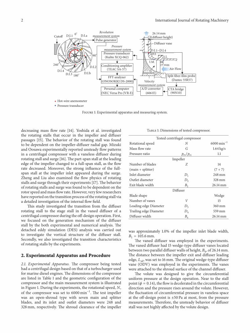
Figure 1: Experimental apparatus and measuring system.
decreasing mass flow rate [14]. Yoshida et al. investigatedthe rotating stalls that occur in the impeller and diffuserpassages [15]. The behavior of the rotating stall was foundto be dependent on the impeller-diffuser radial gap. Mizukiand Oosawa experimentally reported unsteady flow patternsin a centrifugal compressor with a vaneless diffuser duringrotating stall and surge [16].The part-span stall at the leadingedge of the impeller changed to a full-span stall, as the flowrate decreased. Moreover, the strong influence of the full-span stall at the impeller inlet appeared during the surge.Zheng and Liu also examined the flow physics of rotatingstalls and surge through their experiments [17]. The behaviorof rotating stalls and surge was found to be dependent on therotor speed andmass flow rate. However, very few researchershave reported on the transition process of the rotating stall viaa detailed investigation of the internal flow field.
This study investigated the transition from the diffuserrotating stall to the stage stall in the vaned diffuser of acentrifugal compressor during the off-design operation. First,we focused on the generation mechanism of the diffuserstall by the both experimental and numerical analysis. Thedetached eddy simulation (DES) analysis was carried outto investigate the vortical structure of the diffuser stall.Secondly, we also investigated the transition characteristicsof rotating stalls by the experiments.
2. Experimental Apparatus and Procedure
2.1. Experimental Apparatus. The compressor being testedhad a centrifugal design based on that of a turbocharger usedfor marine diesel engines. The dimensions of the compressorare listed in Table 1 and the geometric configuration of thecompressor and the main measurement system is illustratedin Figure 1. During the experiments, the rotational speed,𝑁,of the compressor was set to 6000min−1. The test impellerwas an open-shroud type with seven main and splitterblades, and its inlet and outlet diameters were 248 and328mm, respectively. The shroud clearance of the impeller
Table 1: Dimensions of tested compressor.
Tested centrifugal compressorRotational speed N 6000min−1
Mass flow rate G 1.64 kg/sPressure ratio 𝑝𝑡5/𝑝𝑡1 1.1
ImpellerNumber of blades Z 14(main + splitter) (7 + 7)Inlet diameter 𝐷1 248mmOutlet diameter 𝐷2 328mmExit blade width 𝐵2 26.14mm
DiffuserBlade shape WedgeNumber of vanes V 15Leading edge Diameter 𝐷3 360mmTrailing edge Diameter 𝐷4 559mmDiffuser width 𝐵4 26.14mm
was approximately 1.0% of the impeller inlet blade width,𝐵1 = 105.6mm.
The vaned diffuser was employed in the experiments.The vaned diffuser had 15 wedge-type diffuser vanes locatedbetween two parallel diffuser walls of height, 𝐵4, of 26.14mm.The distance between the impeller exit and diffuser leadingedge, 𝐿 𝑖𝑑, was set to 16mm.The original wedge-type diffuservane (ODV) was employed in the experiments. The vaneswere attached to the shroud surface of the channel diffuser.
The volute was designed to give the circumferentialuniform pressure at the design operation. Near to the stallpoint (𝜙 = 0.14), the flow is decelerated in the circumferentialdirection and the pressure rises around the volute. However,the fluctuation of circumferential pressure in vaneless spaceat the off-design point is ±50 Pa at most, from the pressuremeasurements. Therefore, the unsteady behavior of diffuserstall was not highly affected by the volute design.
International Journal of Rotating Machinery 3
RANSLES
Impeller
Tip Clearance
A
Impeller
ShroudShroud
A
(a) Impeller passage
RANSLES
Di�user
L.E.
B BL.E.
L.E.
Shro
ud
Shroud
Shro
ud
s.s.s.s. s.s.
(b) Diffuser passage
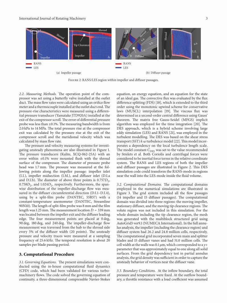
Figure 2: RANS/LES region within impeller and diffuser passages.
2.2. Measuring Methods. The operation point of the com-pressor was set using a butterfly valve installed at the outletduct.Themass flow rates were calculated using an orifice flowmeter and a thermocouple installed at the outlet duct end.Thepressure-rise characteristics were measured using a differen-tial pressure transducer (Yamatake JTD920A) installed at theexit of the compressor scroll.The error of differential pressureprobe was less than ±0.1%.Themeasuring bandwidth is from2.0 kPa to 14MPa. The total pressure rise at the compressorexit was calculated by the pressure rise at the exit of thecompressor scroll and the meridional velocity which wascalculated by mass flow rate.
The pressure and velocity measuring systems for investi-gating unsteady phenomena are also illustrated in Figure 1.The pressure transducers (Kulite, XCQ-062-25A) with anerror within ±0.1% were mounted flush with the shroudsurface of the compressor. The diameter of pressure probehead was 1.7mm. The pressure was measured at the fol-lowing points along the impeller passage: impeller inlet(I.I.), impeller midsection (I.M.), and diffuser inlet (D.I.aand D.I.b). The diameter of above three points is 0.757𝐷2,0.758𝐷2, and 1.024𝐷2, respectively. Furthermore, the span-wise distribution of the impeller-discharge flow was mea-sured in the diffuser circumferential direction (D.I.1–D.I.4),using by a split-film probe (DANTEC, 55R57) with aconstant-temperature anemometer (DANTEC, Streamline90N10).The length of split-film probe was 8mm and the filmlength was 1.25mm.Themeasurement location𝐷 = 339mmwas located between the impeller exit and the diffuser leadingedge. The four measurement points are placed at 0 deg,90 deg, 180 deg, and 240 deg. The impeller-discharge flowmeasurement was traversed from the hub to the shroud sideevery 5% of the diffuser width (20 points). The unsteadypressure and velocity traces were measured at a samplingfrequency of 25.6 kHz. The temporal resolution is about 20samples per blade passing period.
3. Computational Procedure
3.1. Governing Equations. The present simulations were con-ducted using the in-house computational fluid dynamics(CFD) code, which had been validated for various turbo-machinery flows. The code solved the governing equation ofcontinuity, a three-dimensional compressible Navier-Stokes
equation, an energy equation, and an equation for the stateof an ideal gas. The convective flux was evaluated by the fluxdifference splitting (FDS) [18], which is extended to the thirdorder using the monotonic upwind scheme for conservativelaws (MUSCL) interpolation [19]. The viscous flux wasdetermined as a second-order central difference using Gauss’theorem. The matrix free Gauss-Seidel (MFGS) implicitalgorithm was employed for the time integration [20]. TheDES approach, which is a hybrid scheme involving largeeddy simulation (LES) and RANS [21], was employed in theturbulent modelling. The DES was based on the shear stresstransport (SST) k-𝜔 turbulencemodel [22].Thismodel incor-porates a dependency on the local turbulence length scale.The model constant 𝐶DES was set to the value recommendedby Strelets et al. Both Coriolis and centrifugal forces wereconsidered to be inertial force terms in the relative coordinatesystem. The RANS and LES regions of both the impellerand diffuser passages are illustrated in Figure 2. This DESsimulation code could transform the RANS-mode in regionsnear the wall into the LES-mode inside the fluid volume.
3.2. Computational Domains. The computational domainsemployed in the numerical simulations are illustrated inFigure 3. The grid system included all the flow passages(14 impeller and 15 diffuser passages). The computationaldomain was divided into three regions: the moving impeller,stationary diffuser, and the moving tip clearance regions.Thevolute region was not included in this simulation. For thewhole domain including the tip clearance region, the meshwas generated with the multiblock structured grid usingAutoGrid5 ver9.1 (NUMECA International). In the full annu-lus analysis, the impeller (including the clearance region) anddiffuser system had 26.2 and 24.8 million cells, respectively.The computational grid incorporated seven main and splitterblades and 15 diffuser vanes and had 51.0 million cells. Thecell width at the walls was 0.1 𝜇m,which corresponded to a y+parameter that was approximately equal to one along all solidsurfaces. From the grid dependency test in partial annulusanalysis, the grid density was sufficient in order to capture theunsteady behavior of vortices near the diffuser vane.
3.3. Boundary Conditions. At the inflow boundary, the totalpressure and temperature were fixed. At the outflow bound-ary, a throttle resistance with a load coefficient was assumed

4 International Journal of Rotating Machinery
Impeller
Di�user
Sliding mesh
Figure 3: Overview of computational grid.
to exist between the boundary and the external atmosphere.The mass flow rate was not fixed at the outlet boundarybecause we assumed the throttle resistance with a loadcoefficient in order to simulate the velocity and pressurefluctuation caused by stall.We already observed themass flowfluctuation at the exit of the compressor in both experimentsand numerical simulations. Therefore, the static pressure atthe outlet boundary was related to themass flow rate throughthe boundary. Across the sliding boundary separating themoving impeller and stationary diffuser frames, the mostrecent data on one side was interpolated to obtain the datafor the opposite side by using a sliding mesh for unsteadysimulation. Nonslip and adiabatic conditions were adoptedfor the wall conditions.
4. Results and Discussion
4.1. Stall Characteristics of Tested Compressor. The experi-mental and numerical results of compressor performanceare exhibited in Figure 4. The numerical total pressure-risecharacteristics were obtained from DES unsteady analysis.The flow and total pressure-rise coefficients are defined asfollows:
𝜙 = 60𝑄𝜋2𝐷22𝐵2𝑁,
Ψ𝑡 = 602Δ𝑝𝑡𝜌𝜋2𝐷22𝑁2/2 .
(1)
The ODV experimental results were denoted by the blackcircles in the figure.The simulations were conducted at sevenoperating points from the design point (𝜙opt = 0.24) tothe deep stall point (𝜙 = 0.10). The time-averaged resultsof the unsteady DES analysis were in good agreement withthe measured results obtained using the ODV, with the
ODV (EXP)ODV (CFD)
Stall region
0.15 0.20 0.250.10 0.30Flow coe�cient �휙
0.90
1.00
1.10
1.20
1.30
Tota
l pre
ssur
e-ris
e coe
�ci
ent�휓
t
�휙opt
Figure 4: Compressor performance.
exception of results at stall point (𝜙 = 0.14 and 0.10). Onereason for this is that the additional loss from the volutewas not concluded in this numerical simulation. Particularlyat deep stall point (𝜙 = 0.10), the compressor performancedata obtained numerically, using CFD, was higher in valuethan that obtained experimentally. The resulting questionabout the performance remarkably mismatch at 𝜙 = 0.10 isconsidered later in detail.
To investigate the unsteady characteristics of rotatingstall, the impeller-discharge flow was measured with a split-film anemometer at 𝜙 = 0.14 and 0.10.The spatial distributionof the FFT (Fast Fourier Transformation) results in thespanwise direction is shown in Figure 5. The vertical axisrepresents the intensity of radial velocity fluctuation. Themeasurement of flow coefficient, 𝜙= 0.14, shows that the largeintensity of velocity fluctuations occurred at 25Hz near theshroud side. We have already reported that these unsteadyphenomena at 25Hz, which were equivalent to 25% of theimpeller rotational speed, were caused by the rotating stallwithin the diffuser passages [12]. Therefore, this disturbance,as illustrated in Figure 5(a), was considered to result from thediffuser stall fluctuations.When themass flow decreased (𝜙 =0.10), the diffuser stall fluctuation was not found and a largeintensity velocity fluctuation occurred at 22Hz in Figure 5(b).From a previous study [23], we found that the large intensityfluctuations, called “stage stall,” rotated within the impellerand diffuser passages. In comparison with the diffuser stall,the stage stall cell had a much larger intensity of velocityfluctuation over the entire span, especially near the hub side.In addition, from the pressure experiments, the number ofdiffuser and stage stall cell was found to be one. Thus, therotating stall behavior of the tested compressor varied withthe decreasing mass flow rate.

International Journal of Rotating Machinery 5
0
2040
6080
100 2040
6080
1000
Frequency f (Hz)Span from shroud (%)
00.10.20.30.40.5
Velo
city
�uc
tuat
ion
(m/s
)
25 [Hz]
(a) 𝜙 = 0.14
2040
6080
100
0
020
4060
80100
Frequency f (Hz)Span from shroud (%)
00.51.01.52.0
Velo
city
�uc
tuat
ion
(m/s
)
22 [Hz]
(b) 𝜙 = 0.10
Figure 5: Distribution of velocity fluctuation in spanwise direction (ODV).
4.2. Structure of Diffuser Stall Cell. First, the rotationalstructure of the diffuser stall cell at flow coefficient 𝜙 = 0.14was investigated using numerical analysis. To investigate theunsteady characteristics of rotating stall, the casing wall staticpressure fluctuation was measures at two positions (D.I.aand D.I.b). The experimental and numerical casing pressuretraces are presented in Figure 6. The red lines represent thelow-pass filtered traces and the low-pass filter frequencieswere set to 30Hz. From the both experimental and numericaltraces, the disturbance that was propagated in vaneless spacecan be observed. The rotational speed of this disturbancewas approximately 25% of impeller speed. The unsteadyphenomena at 25Hz, which were equivalent to 25% ofimpeller rotational speed, were caused by the diffuser rotatingstall. In addition, the influence of impeller stall fluctuationcould be excluded because the scale of disturbances caused bythe impeller stall were much smaller than that of the diffuserstall at diffuser inlet from Figure 5. Therefore, the numericalresults for diffuser stall were in good agreement with theresults obtained by the experiments.
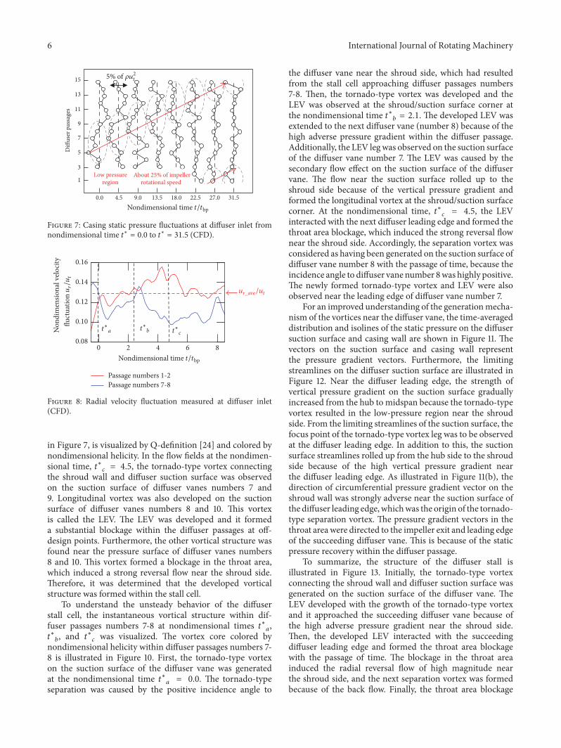
Furthermore, the instantaneous casing pressure fluctu-ations in the vaneless space at nondimensional times 𝑡∗= 0.0–31.5 are illustrated in Figure 7. The vertical axisis each diffuser vane, which was labelled with numbersfrom one to fifteen. The low casing static pressure region,which is represented by a black dashed circle, propagatedto the next diffuser passage as time passed. The rotationalspeed of this region was approximately 25% of the impellerrotational speed. Thus, it may be concluded that this lowstatic pressure region was caused by the diffuser rotating stallcell. Furthermore, the radial velocity fluctuation measuredat the diffuser inlet is illustrated in Figure 8. The red andblue lines represent the diffuser passages numbers 1-2 and 7-8, respectively. The red dashed line, as illustrated in Figure 8,indicates the average of radial velocities calculated for alldiffuser passages. As shown in this figure, the radial velocityof the diffuser passage numbers 7-8 was lower than theaverage radial velocity, because the diffuser rotating stall cellwas approaching the diffuser passage numbers 7-8 from thenondimensional time, 𝑡∗𝑎 = 0.0, as illustrated in Figure 7.At the nondimensional time, 𝑡∗𝑐 = 4.5, the radial velocity of
0
Time traceFiltered trace
Pres
sure
�uc
tuat
ion
(kPa
)
CFD
EXP
2
0
2
2
0
2
0
2 4 6 80Time in rotor revolutions
−2
−2
−2
−2
D.I.b (120 deg)
D.I.a (0 deg)
D.I.a (0 deg)
D.I.b (120 deg)
Figure 6: Casing wall pressure traces measured at diffuser inletcircumferential direction (D.I.a and D.I.b).
the diffuser passage numbers 7-8 was significantly decreased.Therefore, these results suggested that the flow within thediffuser passage was stalled by the blockage effect of thediffuser stall cell formation.
Then, the instantaneous vortical structure of the lowstatic pressure region at the nondimensional time, 𝑡∗𝑐 =4.5, is illustrated in Figure 9. The vortex structure withinseveral stalled diffuser passages numbers 7–11, as illustrated
6 International Journal of Rotating Machinery
About 25% of impeller rotational speed
Low pressureregion
5% of �휌u2t
22.5 27.0 31.513.5 18.04.5 9.00.0t/tbpNondimensional time
1
3
5
7
9
11
13
15
Di�
user
pas
sage
s
Figure 7: Casing static pressure fluctuations at diffuser inlet fromnondimensional time 𝑡∗ = 0.0 to 𝑡∗ = 31.5 (CFD).
Non
dim
ensio
nal v
eloci
ty
Passage numbers 7-8Passage numbers 1-2
2 4 6 80t/tbpNondimensional time
ur_ /ut
0.16
0.14
0.12
0.10
0.08
ur/u
t
t∗a t∗b t∗c
ave
�uct
uatio
n
Figure 8: Radial velocity fluctuation measured at diffuser inlet(CFD).
in Figure 7, is visualized by Q-definition [24] and colored bynondimensional helicity. In the flow fields at the nondimen-sional time, 𝑡∗𝑐 = 4.5, the tornado-type vortex connectingthe shroud wall and diffuser suction surface was observedon the suction surface of diffuser vanes numbers 7 and9. Longitudinal vortex was also developed on the suctionsurface of diffuser vanes numbers 8 and 10. This vortexis called the LEV. The LEV was developed and it formeda substantial blockage within the diffuser passages at off-design points. Furthermore, the other vortical structure wasfound near the pressure surface of diffuser vanes numbers8 and 10. This vortex formed a blockage in the throat area,which induced a strong reversal flow near the shroud side.Therefore, it was determined that the developed vorticalstructure was formed within the stall cell.
To understand the unsteady behavior of the diffuserstall cell, the instantaneous vortical structure within dif-fuser passages numbers 7-8 at nondimensional times 𝑡∗𝑎,𝑡∗𝑏, and 𝑡∗𝑐 was visualized. The vortex core colored bynondimensional helicity within diffuser passages numbers 7-8 is illustrated in Figure 10. First, the tornado-type vortexon the suction surface of the diffuser vane was generatedat the nondimensional time 𝑡∗𝑎 = 0.0. The tornado-typeseparation was caused by the positive incidence angle to
the diffuser vane near the shroud side, which had resultedfrom the stall cell approaching diffuser passages numbers7-8. Then, the tornado-type vortex was developed and theLEV was observed at the shroud/suction surface corner atthe nondimensional time 𝑡∗𝑏 = 2.1. The developed LEV wasextended to the next diffuser vane (number 8) because of thehigh adverse pressure gradient within the diffuser passage.Additionally, the LEV legwas observed on the suction surfaceof the diffuser vane number 7. The LEV was caused by thesecondary flow effect on the suction surface of the diffuservane. The flow near the suction surface rolled up to theshroud side because of the vertical pressure gradient andformed the longitudinal vortex at the shroud/suction surfacecorner. At the nondimensional time, 𝑡∗𝑐 = 4.5, the LEVinteracted with the next diffuser leading edge and formed thethroat area blockage, which induced the strong reversal flownear the shroud side. Accordingly, the separation vortex wasconsidered as having been generated on the suction surface ofdiffuser vane number 8 with the passage of time, because theincidence angle to diffuser vane number 8was highly positive.The newly formed tornado-type vortex and LEV were alsoobserved near the leading edge of diffuser vane number 7.
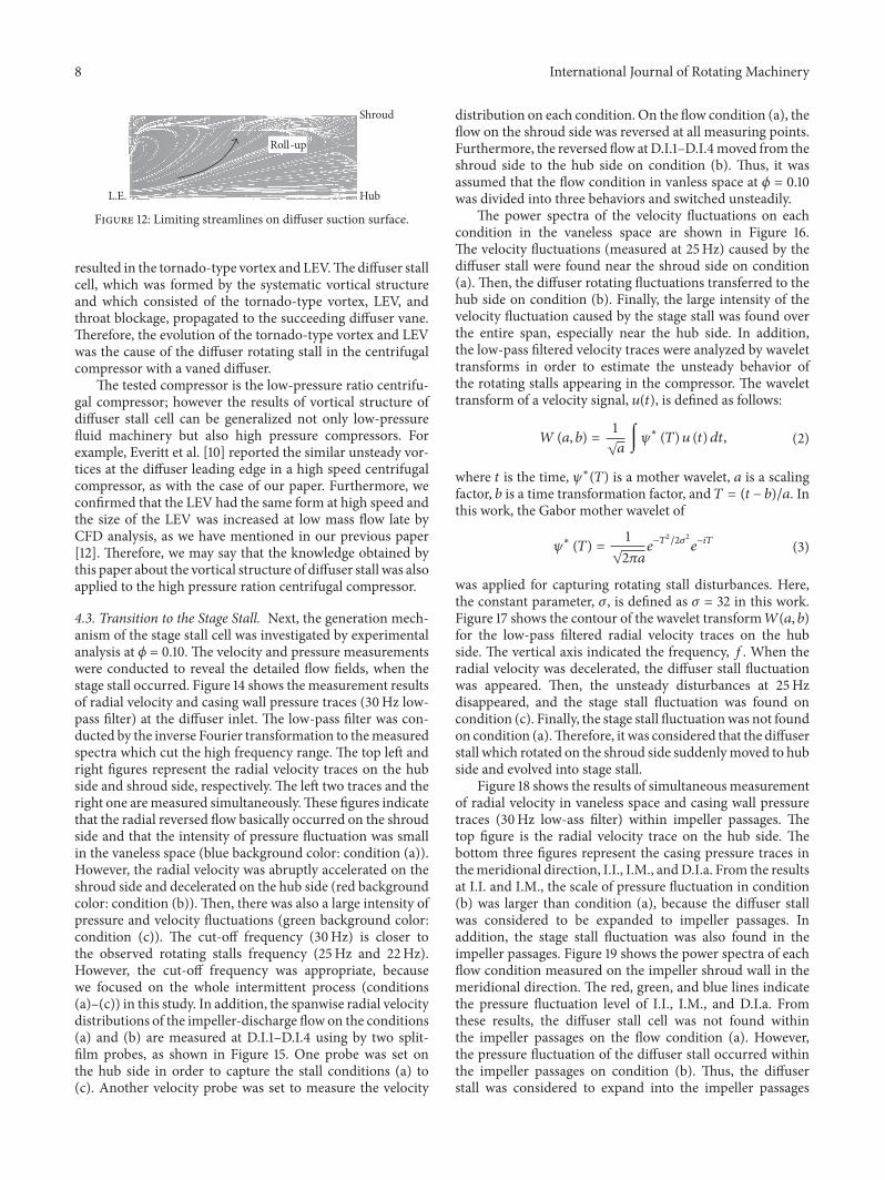
For an improved understanding of the generationmecha-nism of the vortices near the diffuser vane, the time-averageddistribution and isolines of the static pressure on the diffusersuction surface and casing wall are shown in Figure 11. Thevectors on the suction surface and casing wall representthe pressure gradient vectors. Furthermore, the limitingstreamlines on the diffuser suction surface are illustrated inFigure 12. Near the diffuser leading edge, the strength ofvertical pressure gradient on the suction surface graduallyincreased from the hub to midspan because the tornado-typevortex resulted in the low-pressure region near the shroudside. From the limiting streamlines of the suction surface, thefocus point of the tornado-type vortex leg was to be observedat the diffuser leading edge. In addition to this, the suctionsurface streamlines rolled up from the hub side to the shroudside because of the high vertical pressure gradient nearthe diffuser leading edge. As illustrated in Figure 11(b), thedirection of circumferential pressure gradient vector on theshroud wall was strongly adverse near the suction surface ofthe diffuser leading edge, whichwas the origin of the tornado-type separation vortex. The pressure gradient vectors in thethroat area were directed to the impeller exit and leading edgeof the succeeding diffuser vane. This is because of the staticpressure recovery within the diffuser passage.
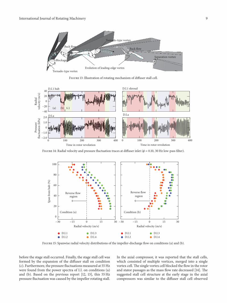
To summarize, the structure of the diffuser stall isillustrated in Figure 13. Initially, the tornado-type vortexconnecting the shroud wall and diffuser suction surface wasgenerated on the suction surface of the diffuser vane. TheLEV developed with the growth of the tornado-type vortexand it approached the succeeding diffuser vane because ofthe high adverse pressure gradient near the shroud side.Then, the developed LEV interacted with the succeedingdiffuser leading edge and formed the throat area blockagewith the passage of time. The blockage in the throat areainduced the radial reversal flow of high magnitude nearthe shroud side, and the next separation vortex was formedbecause of the back flow. Finally, the throat area blockage

International Journal of Rotating Machinery 7
1
Nondimensional helicityTornado-type
vortex
Back �ow
Evolution of LEV
Blockage
7 8
9
10
11
Tornado-type vortex Back �ow
Blockage
LEV Leading-edgeseparation
−1
t∗c = 4.5
Figure 9: Instantaneous vortical structure of diffuser stall within diffuser passages number 7 to number 11.
1Nondimensional helicity
7 8
Rotational direction
Tornado-type vortex
L.E.
L.E.
s.s.
−1
Shroud
(a) 𝑡∗𝑎 = 0.0
7 8
Rotational direction
Tornado-type vortex
L.E.
LEV
L.E.
s.s.
Shroud
1Nondimensional helicity
−1
(b) 𝑡∗𝑏 = 2.1
7 8
Rotational direction
Tornado-type vortex
L.E.
LEV
Blockage
L.E.
s.s.
Shroud
1Nondimensional helicity
−1
(c) 𝑡∗𝑐 = 4.5
Figure 10: Instantaneous vortical structure within diffuser passage numbers 7-8 at nondimensional time 𝑡∗𝑎, 𝑡∗𝑏, and 𝑡∗𝑐.
Pressure gradient vector Hub
Shroud
L.E.
105.0 108.6Static pressure (kPa)
z
(a) Suction surface
Impeller rotation
L.E.
s.s.p.s.
Pressure gradient vector
�휃
(b) Shroud surface
Figure 11: Distribution of static pressure on diffuser suction surface and casing wall.
8 International Journal of Rotating Machinery
Roll-up
Hub
Shroud
L.E.
Figure 12: Limiting streamlines on diffuser suction surface.
resulted in the tornado-type vortex and LEV.Thediffuser stallcell, which was formed by the systematic vortical structureand which consisted of the tornado-type vortex, LEV, andthroat blockage, propagated to the succeeding diffuser vane.Therefore, the evolution of the tornado-type vortex and LEVwas the cause of the diffuser rotating stall in the centrifugalcompressor with a vaned diffuser.
The tested compressor is the low-pressure ratio centrifu-gal compressor; however the results of vortical structure ofdiffuser stall cell can be generalized not only low-pressurefluid machinery but also high pressure compressors. Forexample, Everitt et al. [10] reported the similar unsteady vor-tices at the diffuser leading edge in a high speed centrifugalcompressor, as with the case of our paper. Furthermore, weconfirmed that the LEV had the same form at high speed andthe size of the LEV was increased at low mass flow late byCFD analysis, as we have mentioned in our previous paper[12]. Therefore, we may say that the knowledge obtained bythis paper about the vortical structure of diffuser stall was alsoapplied to the high pressure ration centrifugal compressor.
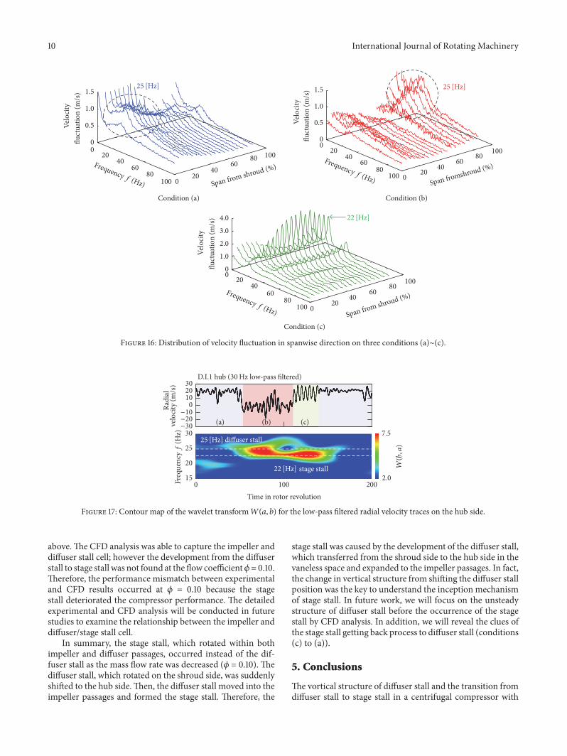
4.3. Transition to the Stage Stall. Next, the generation mech-anism of the stage stall cell was investigated by experimentalanalysis at 𝜙 = 0.10. The velocity and pressure measurementswere conducted to reveal the detailed flow fields, when thestage stall occurred. Figure 14 shows the measurement resultsof radial velocity and casing wall pressure traces (30Hz low-pass filter) at the diffuser inlet. The low-pass filter was con-ducted by the inverse Fourier transformation to themeasuredspectra which cut the high frequency range. The top left andright figures represent the radial velocity traces on the hubside and shroud side, respectively. The left two traces and theright one aremeasured simultaneously.These figures indicatethat the radial reversed flow basically occurred on the shroudside and that the intensity of pressure fluctuation was smallin the vaneless space (blue background color: condition (a)).However, the radial velocity was abruptly accelerated on theshroud side and decelerated on the hub side (red backgroundcolor: condition (b)). Then, there was also a large intensity ofpressure and velocity fluctuations (green background color:condition (c)). The cut-off frequency (30Hz) is closer tothe observed rotating stalls frequency (25Hz and 22Hz).However, the cut-off frequency was appropriate, becausewe focused on the whole intermittent process (conditions(a)–(c)) in this study. In addition, the spanwise radial velocitydistributions of the impeller-discharge flow on the conditions(a) and (b) are measured at D.I.1–D.I.4 using by two split-film probes, as shown in Figure 15. One probe was set onthe hub side in order to capture the stall conditions (a) to(c). Another velocity probe was set to measure the velocity
distribution on each condition. On the flow condition (a), theflow on the shroud side was reversed at all measuring points.Furthermore, the reversed flow atD.I.1–D.I.4moved from theshroud side to the hub side on condition (b). Thus, it wasassumed that the flow condition in vanless space at 𝜙 = 0.10was divided into three behaviors and switched unsteadily.
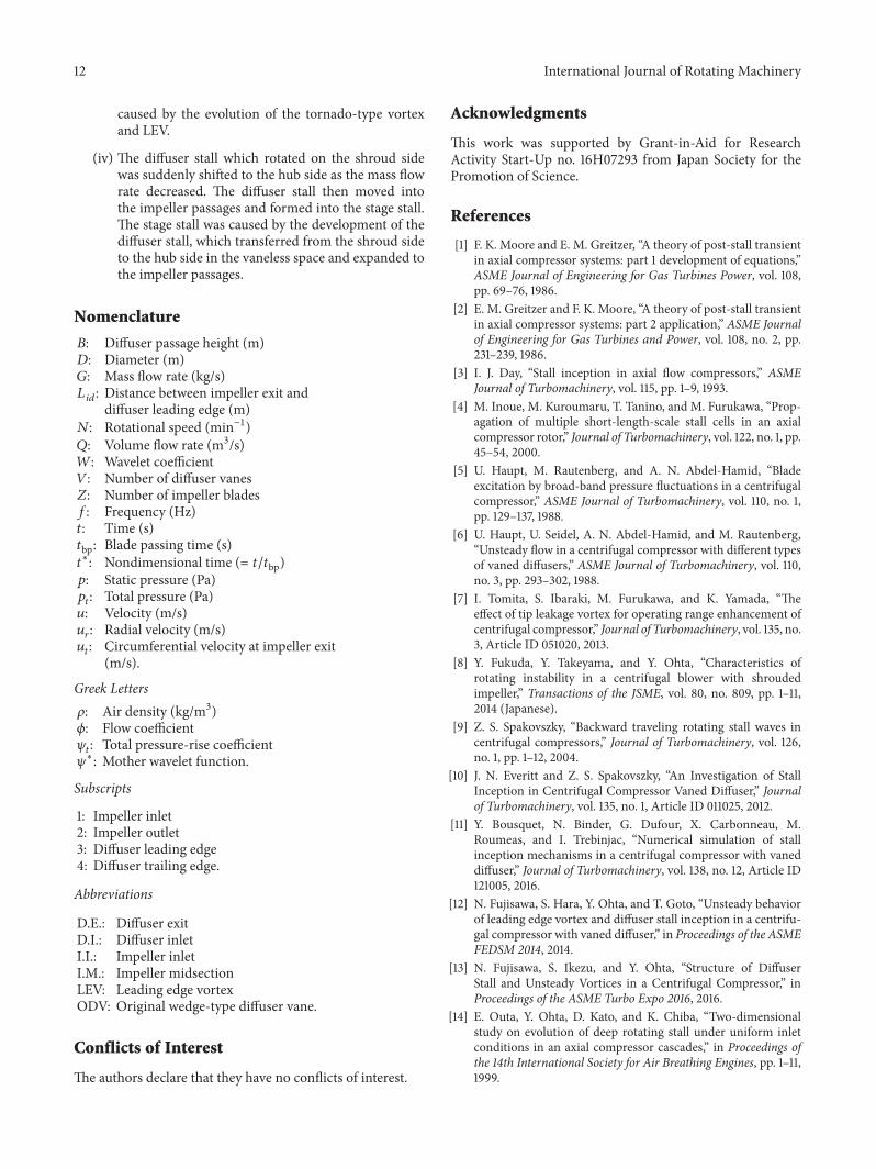
The power spectra of the velocity fluctuations on eachcondition in the vaneless space are shown in Figure 16.The velocity fluctuations (measured at 25Hz) caused by thediffuser stall were found near the shroud side on condition(a). Then, the diffuser rotating fluctuations transferred to thehub side on condition (b). Finally, the large intensity of thevelocity fluctuation caused by the stage stall was found overthe entire span, especially near the hub side. In addition,the low-pass filtered velocity traces were analyzed by wavelettransforms in order to estimate the unsteady behavior ofthe rotating stalls appearing in the compressor. The wavelettransform of a velocity signal, 𝑢(𝑡), is defined as follows:
𝑊(𝑎, 𝑏) = 1√𝑎 ∫𝜓
∗ (𝑇) 𝑢 (𝑡) 𝑑𝑡, (2)
where 𝑡 is the time, 𝜓∗(𝑇) is a mother wavelet, 𝑎 is a scalingfactor, 𝑏 is a time transformation factor, and 𝑇 = (𝑡 − 𝑏)/𝑎. Inthis work, the Gabor mother wavelet of
𝜓∗ (𝑇) = 1√2𝜋𝑎𝑒
−𝑇2/2𝜎2𝑒−𝑖𝑇 (3)
was applied for capturing rotating stall disturbances. Here,the constant parameter, 𝜎, is defined as 𝜎 = 32 in this work.Figure 17 shows the contour of the wavelet transform𝑊(𝑎, 𝑏)for the low-pass filtered radial velocity traces on the hubside. The vertical axis indicated the frequency, 𝑓. When theradial velocity was decelerated, the diffuser stall fluctuationwas appeared. Then, the unsteady disturbances at 25Hzdisappeared, and the stage stall fluctuation was found oncondition (c). Finally, the stage stall fluctuationwas not foundon condition (a).Therefore, it was considered that the diffuserstall which rotated on the shroud side suddenlymoved to hubside and evolved into stage stall.
Figure 18 shows the results of simultaneous measurementof radial velocity in vaneless space and casing wall pressuretraces (30Hz low-ass filter) within impeller passages. Thetop figure is the radial velocity trace on the hub side. Thebottom three figures represent the casing pressure traces inthemeridional direction, I.I., I.M., andD.I.a. From the resultsat I.I. and I.M., the scale of pressure fluctuation in condition(b) was larger than condition (a), because the diffuser stallwas considered to be expanded to impeller passages. Inaddition, the stage stall fluctuation was also found in theimpeller passages. Figure 19 shows the power spectra of eachflow condition measured on the impeller shroud wall in themeridional direction. The red, green, and blue lines indicatethe pressure fluctuation level of I.I., I.M., and D.I.a. Fromthese results, the diffuser stall cell was not found withinthe impeller passages on the flow condition (a). However,the pressure fluctuation of the diffuser stall occurred withinthe impeller passages on condition (b). Thus, the diffuserstall was considered to expand into the impeller passages
International Journal of Rotating Machinery 9
Back �owBack �ow
Evolution of leading-edge vortexTornado-type vortex
Tornado-type vortex
Separation vortexBlockage
Figure 13: Illustration of rotating mechanism of diffuser stall cell.
4020
0
D.I.1 hub
Radi
alPr
essu
re�u
ctua
tion
(kPa
)
D.I.a
velo
city
(m/s
)
D.I.1 shroud
D.I.a
(a) (b) (c)−20
−40
−2.0
−1.0
0
1.0
2.0
100 200 3000 400Time in rotor revolution
100 200 300 4000Time in rotor revolution
Figure 14: Radial velocity and pressure fluctuation traces at diffuser inlet (𝜙 = 0.10, 30Hz low-pass filter).
Condition (a) Condition (b)
regionReverse �ow Reverse �ow
region
100
80
60
40
20
0
Span
from
hub
(%)
−15 0 3015−30
Radial velocity (m/s)−15 0 3015−30
Radial velocity (m/s)
D.I.1D.I.2
D.I.3D.I.4
D.I.1D.I.2
D.I.3D.I.4
Figure 15: Spanwise radial velocity distributions of the impeller-discharge flow on conditions (a) and (b).
before the stage stall occurred. Finally, the stage stall cell wasformed by the expansion of the diffuser stall on condition(c). Furthermore, the pressure fluctuationsmeasured at 55Hzwere found from the power spectra of I.I. on conditions (a)and (b). Based on the previous report [12, 13], this 55Hzpressure fluctuation was caused by the impeller rotating stall.
In the axial compressor, it was reported that the stall cells,which consisted of multiple vortices, merged into a singlevortex cell.The single vortex cell blocked the flow in the rotorand stator passages as the mass flow rate decreased [14]. Thesuggested stall cell structure at the early stage in the axialcompressors was similar to the diffuser stall cell observed
10 International Journal of Rotating Machinery
020
6080
100 020
4060
80 10040
Velo
city
0
0.5
1.0
1.5
�uct
uatio
n (m
/s)
Frequency f (Hz) Span from shroud (%)
25 [Hz]
020
6080
100 020
4060
80 10040
Velo
city
0
0.5
1.0
1.5
�uct
uatio
n (m
/s)
Frequency f (Hz) Span fromshroud (%)
25 [Hz]
Velo
city
020
6080
100 020
4060
8010040
0
1.0
2.0
3.0
4.0�u
ctua
tion
(m/s
)
Frequency f (Hz) Span from shroud (%)
22 [Hz]
Condition (a) Condition (b)
Condition (c)
Figure 16: Distribution of velocity fluctuation in spanwise direction on three conditions (a)∼(c).
Radi
al
30
20
15
25
2.0
7.5
Time in rotor revolution 100 2000
(a) (b) (c)
Freq
uenc
yf
(Hz)
W(b,a
)
−30−20
0−10
102030
velo
city
(m/s
)
(30 Hz low-pass �ltered)D.I.1 hub
22 [Hz]
25 [Hz] di�user stall
stage stall
Figure 17: Contour map of the wavelet transform𝑊(𝑎, 𝑏) for the low-pass filtered radial velocity traces on the hub side.
above.The CFD analysis was able to capture the impeller anddiffuser stall cell; however the development from the diffuserstall to stage stall was not found at the flow coefficient𝜙=0.10.Therefore, the performance mismatch between experimentaland CFD results occurred at 𝜙 = 0.10 because the stagestall deteriorated the compressor performance. The detailedexperimental and CFD analysis will be conducted in futurestudies to examine the relationship between the impeller anddiffuser/stage stall cell.
In summary, the stage stall, which rotated within bothimpeller and diffuser passages, occurred instead of the dif-fuser stall as the mass flow rate was decreased (𝜙 = 0.10). Thediffuser stall, which rotated on the shroud side, was suddenlyshifted to the hub side.Then, the diffuser stall moved into theimpeller passages and formed the stage stall. Therefore, the
stage stall was caused by the development of the diffuser stall,which transferred from the shroud side to the hub side in thevaneless space and expanded to the impeller passages. In fact,the change in vertical structure from shifting the diffuser stallposition was the key to understand the inception mechanismof stage stall. In future work, we will focus on the unsteadystructure of diffuser stall before the occurrence of the stagestall by CFD analysis. In addition, we will reveal the clues ofthe stage stall getting back process to diffuser stall (conditions(c) to (a)).
5. Conclusions
The vortical structure of diffuser stall and the transition fromdiffuser stall to stage stall in a centrifugal compressor with

International Journal of Rotating Machinery 11
100
101
102
103
104
D.I.1 Hub
102
103
104
105
106
(a) (b) (c)
Stat
icpr
essu
re (k
Pa)
Stat
icpr
essu
re (k
Pa)
Stat
icpr
essu
re (k
Pa)
Radi
al
−30
−20
−10
0102030
velo
city
(m/s
)
100
101
102
103
104
100 200 300 4000Time in rotor revolution
Figure 18: Radial velocity at diffuser inlet and static pressure traces at meridional direction (𝜙 = 0.10, 30Hz low-pass filter).
Pres
sure
�uc
tuat
ion
0 20 40 60 80 100 0 20 40 60 80 100
Condition (a) Condition (b) Condition (c)
110
120
130
140
150
leve
l dB
Frequency f (Hz) Frequency f (Hz)Frequency f (Hz)8040 6020 1000
I.I.I.M.
D.I.a I.I.I.M.
D.I.a I.I.I.M.
D.I.a
25 [Hz] 25 [Hz]
22 [Hz]55 [Hz]55 [Hz]
Figure 19: Power spectra of pressure fluctuations in impeller passage (𝜙 = 0.10).
a vaned diffuser were investigated by experimentation andthrough CFD analysis.
The results can be summarized as follows:
(i) In the tested compressor, the diffuser stall rotated at25%of the impeller rotational speed during off-designflow operation. Both the experimental and numericalresults revealed the rotation of the diffuser stall cellin the vaneless space on the shroud side of the flowpassage. In addition, large fluctuations occurred at22Hz, and were caused by stage stall when the massflow rate decreased. The stage stall expanded over theentire span in the vaneless space.
(ii) The vortical structure of the diffuser stall cell con-sisted of the tornado-type vortex, LEV, and throatblockage. The stall cell’s typical vortical structurepropagated to the succeeding diffuser passages.
(iii) The tornado-type separation was caused by the pos-itive incidence angle to the diffuser vane near theshroud side. The LEV developed with the growth ofthe tornado-type vortex and extended to the succeed-ing diffuser vane. The developed LEV subsequentlyinteracted with the succeeding diffuser leading edgeand formed the throat area blockage. Finally, thetornado-type vortex and LEV were developed by thethroat area blockage. The diffuser rotating stall was
12 International Journal of Rotating Machinery
caused by the evolution of the tornado-type vortexand LEV.
(iv) The diffuser stall which rotated on the shroud sidewas suddenly shifted to the hub side as the mass flowrate decreased. The diffuser stall then moved intothe impeller passages and formed into the stage stall.The stage stall was caused by the development of thediffuser stall, which transferred from the shroud sideto the hub side in the vaneless space and expanded tothe impeller passages.
Nomenclature
𝐵: Diffuser passage height (m)𝐷: Diameter (m)𝐺: Mass flow rate (kg/s)𝐿 𝑖𝑑: Distance between impeller exit and
diffuser leading edge (m)𝑁: Rotational speed (min−1)𝑄: Volume flow rate (m3/s)𝑊: Wavelet coefficient𝑉: Number of diffuser vanes𝑍: Number of impeller blades𝑓: Frequency (Hz)𝑡: Time (s)𝑡bp: Blade passing time (s)𝑡∗: Nondimensional time (= 𝑡/𝑡bp)𝑝: Static pressure (Pa)𝑝𝑡: Total pressure (Pa)𝑢: Velocity (m/s)𝑢𝑟: Radial velocity (m/s)𝑢𝑡: Circumferential velocity at impeller exit
(m/s).
Greek Letters𝜌: Air density (kg/m3)𝜙: Flow coefficient𝜓𝑡: Total pressure-rise coefficient𝜓∗: Mother wavelet function.
Subscripts
1: Impeller inlet2: Impeller outlet3: Diffuser leading edge4: Diffuser trailing edge.
Abbreviations
D.E.: Diffuser exitD.I.: Diffuser inletI.I.: Impeller inletI.M.: Impeller midsectionLEV: Leading edge vortexODV: Original wedge-type diffuser vane.
Conflicts of Interest
The authors declare that they have no conflicts of interest.
Acknowledgments
This work was supported by Grant-in-Aid for ResearchActivity Start-Up no. 16H07293 from Japan Society for thePromotion of Science.
References
[1] F. K. Moore and E. M. Greitzer, “A theory of post-stall transientin axial compressor systems: part 1 development of equations,”ASME Journal of Engineering for Gas Turbines Power, vol. 108,pp. 69–76, 1986.
[2] E. M. Greitzer and F. K. Moore, “A theory of post-stall transientin axial compressor systems: part 2 application,” ASME Journalof Engineering for Gas Turbines and Power, vol. 108, no. 2, pp.231–239, 1986.
[3] I. J. Day, “Stall inception in axial flow compressors,” ASMEJournal of Turbomachinery, vol. 115, pp. 1–9, 1993.
[4] M. Inoue, M. Kuroumaru, T. Tanino, and M. Furukawa, “Prop-agation of multiple short-length-scale stall cells in an axialcompressor rotor,” Journal of Turbomachinery, vol. 122, no. 1, pp.45–54, 2000.
[5] U. Haupt, M. Rautenberg, and A. N. Abdel-Hamid, “Bladeexcitation by broad-band pressure fluctuations in a centrifugalcompressor,” ASME Journal of Turbomachinery, vol. 110, no. 1,pp. 129–137, 1988.
[6] U. Haupt, U. Seidel, A. N. Abdel-Hamid, and M. Rautenberg,“Unsteady flow in a centrifugal compressor with different typesof vaned diffusers,” ASME Journal of Turbomachinery, vol. 110,no. 3, pp. 293–302, 1988.
[7] I. Tomita, S. Ibaraki, M. Furukawa, and K. Yamada, “Theeffect of tip leakage vortex for operating range enhancement ofcentrifugal compressor,” Journal of Turbomachinery, vol. 135, no.3, Article ID 051020, 2013.
[8] Y. Fukuda, Y. Takeyama, and Y. Ohta, “Characteristics ofrotating instability in a centrifugal blower with shroudedimpeller,” Transactions of the JSME, vol. 80, no. 809, pp. 1–11,2014 (Japanese).
[9] Z. S. Spakovszky, “Backward traveling rotating stall waves incentrifugal compressors,” Journal of Turbomachinery, vol. 126,no. 1, pp. 1–12, 2004.
[10] J. N. Everitt and Z. S. Spakovszky, “An Investigation of StallInception in Centrifugal Compressor Vaned Diffuser,” Journalof Turbomachinery, vol. 135, no. 1, Article ID 011025, 2012.
[11] Y. Bousquet, N. Binder, G. Dufour, X. Carbonneau, M.Roumeas, and I. Trebinjac, “Numerical simulation of stallinception mechanisms in a centrifugal compressor with vaneddiffuser,” Journal of Turbomachinery, vol. 138, no. 12, Article ID121005, 2016.
[12] N. Fujisawa, S. Hara, Y. Ohta, and T. Goto, “Unsteady behaviorof leading edge vortex and diffuser stall inception in a centrifu-gal compressor with vaned diffuser,” in Proceedings of the ASMEFEDSM 2014, 2014.
[13] N. Fujisawa, S. Ikezu, and Y. Ohta, “Structure of DiffuserStall and Unsteady Vortices in a Centrifugal Compressor,” inProceedings of the ASME Turbo Expo 2016, 2016.
[14] E. Outa, Y. Ohta, D. Kato, and K. Chiba, “Two-dimensionalstudy on evolution of deep rotating stall under uniform inletconditions in an axial compressor cascades,” in Proceedings ofthe 14th International Society for Air Breathing Engines, pp. 1–11,1999.

International Journal of Rotating Machinery 13
[15] Y. Yoshida, H. Tsurusaki, Y. Murakami, and Y. Tsujimoto,“otating stalls in centrifugal impeller/vaned diffuser systems (1stReport),” Transactions of the JSME, vol. 56, no. 530, pp. 2991–2998, 1990 (Japanese).
[16] S. Mizuki and Y. Oosawa, “Unsteady flow within centrifugalcompressor channels under rotating stall and surge,” Journal ofTurbomachinery, vol. 114, no. 2, pp. 312–320, 1992.
[17] X. Zheng and A. Liu, “Phenomenon and mechanism of two-regime-surge in a centrifugal compressor,” Journal of Turboma-chinery, vol. 137, no. 8, Article ID 081007, 2015.
[18] J. L. Steger and R. F. Warming, “Flux vector splitting ofthe inviscid gasdynamic equations with application to finite-difference methods,” Journal of Computational Physics, vol. 40,no. 2, pp. 263–293, 1981.
[19] B. van Leer, “Towards the ultimate conservative differencescheme. V. A second-order sequel to Godunov’s method,”Journal of Computational Physics, vol. 32, no. 1, pp. 101–136, 1979.
[20] E. Shima, “A simple implicit scheme for structured/unstruc-tured cfd,” in Proceedings of 29th Fluid Dynamic Conference, pp.325–328, 1997.
[21] P. R. Spalart, M.-H. Jou, M. Strelets, and S. R. Allmaras,“Comments on the feasibility of les for wings and on the hybridrans/les approach, advances in DNS/LES,” in Proceedings of theFirst AFOSR International Conference on DNS/LES, 1997.
[22] M. Strelets, “Detached Eddy simulation of massively separatedflows,” AIAA Paper, Article ID 2001-0879, 2001.
[23] S. Ikezu, N. Fujisawa, and Y. Ohta, “Characteristics of aCentrifugal Compressor with Vaned Diffuser,” in Proceedingsof the 6th Asian Joint Workshop on Thermophysics and FluidScience, 2016.
[24] J. Jeong and F. Hussain, “On the identification of a vortex,”Journal of Fluid Mechanics, vol. 285, pp. 69–94, 1995.

RoboticsJournal of
Hindawi Publishing Corporationhttp://www.hindawi.com Volume 2014
Hindawi Publishing Corporationhttp://www.hindawi.com Volume 2014
Active and Passive Electronic Components
Control Scienceand Engineering
Journal of
Hindawi Publishing Corporationhttp://www.hindawi.com Volume 2014
International Journal of
RotatingMachinery
Hindawi Publishing Corporationhttp://www.hindawi.com Volume 2014
Hindawi Publishing Corporation http://www.hindawi.com
Journal of
Volume 201
Submit your manuscripts athttps://www.hindawi.com
VLSI Design
Hindawi Publishing Corporationhttp://www.hindawi.com Volume 201
Hindawi Publishing Corporationhttp://www.hindawi.com Volume 2014
Shock and Vibration
Hindawi Publishing Corporationhttp://www.hindawi.com Volume 2014
Civil EngineeringAdvances in
Acoustics and VibrationAdvances in
Hindawi Publishing Corporationhttp://www.hindawi.com Volume 2014
Hindawi Publishing Corporationhttp://www.hindawi.com Volume 2014
Electrical and Computer Engineering
Journal of
Advances inOptoElectronics
Hindawi Publishing Corporation http://www.hindawi.com
Volume 2014
The Scientific World JournalHindawi Publishing Corporation http://www.hindawi.com Volume 2014
SensorsJournal of
Hindawi Publishing Corporationhttp://www.hindawi.com Volume 2014
Modelling & Simulation in EngineeringHindawi Publishing Corporation http://www.hindawi.com Volume 2014
Hindawi Publishing Corporationhttp://www.hindawi.com Volume 2014
Chemical EngineeringInternational Journal of Antennas and
Propagation
International Journal of
Hindawi Publishing Corporationhttp://www.hindawi.com Volume 2014
Hindawi Publishing Corporationhttp://www.hindawi.com Volume 2014
Navigation and Observation
International Journal of
Hindawi Publishing Corporationhttp://www.hindawi.com Volume 2014
DistributedSensor Networks
International Journal of