


Languages
Pages
Legal


WPS-350-DOM-A-BLWPS-350-DOM-A-WH
CAMERADOME


3
WPS-350-DOM-A Installation Manual
© 2013 Wirepath Surveillance
(1) WPS-350-DOM-A (1) AC/DC Plug (1) BNC Test Port Adapter (3) Screws (3) Wall Fasteners (1) 3mm Allen key (1) Foam gasket (1) Installation Manual (1) Spare Silica Pack in Vacuum sealed bag
PACKAGE CONTENTS
NOTE 1: A POWER SUPPLY IS NOT INCLUDED WITH THIS CAMERA. The PS-12DC-1A or WPS-PS multiple output power supplies are recommended.
NOTE 2: A Silica Gel package is mounted inside the dome housing. This package should remain inside the housing after installation.

4
WPS-350-DOM-A Installation Manual
OPTIONAL ACCESSORIESWirepath Surveillance offers a wide range of accessories that provide power to the cameras, allow for various mounting options, and make connection to the head end quick and easy.
• WPS-MNT-EXT-DOM Dome Camera Extension Mount Use to extend the camera away from the ceiling, and to hide wires for
locations where wires cannot be placed into the ceiling.
• WPS-MNT-FLUSH-DOM Dome Camera Flush Mount Usetomountthecameraceilingforflushcleanappearance.
• WPS-MNT-L-DOM-WH Dome Camera L Mount Use when the dome is to be mounted away from the wall, and to hide
wires for locations where wires cannot be placed into the wall.
• WPS-MNT-ARM-DOM-WH Dome Camera Arm Mount Use when the dome is to be mounted away from the wall, and to hide
wires for locations where wires cannot be placed into the wall.
MOUNTS
Local Power Supplies
• PS-12DC-1A 12 Volt 1 Amp Power Supply for Cameras & IR Systems
Remote Power SuppliesUse these remote power supplies to power all the cameras in the system from a remote location.
• WPS-PS9-12VDC-10A 9 Output Power Supply - 12V DC, 10A - PTC Fuses
• WPS-PS9-24VAC-12A
9 Output Power Supply - 24V AC, 12A - PTC Fuses • WPS-PS18-12VDC-18A
18 Output Power Supply - 12V DC, 18A - PTC Fuses
Power Supplies

5
WPS-350-DOM-A Installation Manual
© 2013 Wirepath Surveillance
WIRING ACCESSORIES
•WPS-BAL-V-PIGTAIL Mini Passive Video Balun with Pigtail
and Screw Terminals
•WPS-BAL-V-MINI Mini Passive Video Balun with Pigtail
and Screw Terminals
•WPS-BAL-V-COMBO Mini Passive Video Balun with Screw
Terminals Combo PackContains: 1 WPS-BAL-V-PIGTAIL and 1 WPS-BAL-V-MINI
•WPS-BAL-VP Passive Video and Power Balun with
RJ45
•WPS-BAL-VPA Passive Video, Power, Audio Balun
with RJ45
•WPS-BAL-VPD Passive Video, Power, PTZ Balun
with RJ45
•WPS-ACC-PWR-F&WPS-ACC-PWR-M DC Power Plug with Screw
TerminalsAvailable in Male and Female version 10packs.
•WPS-ACC-PWR-1X2 DC Power Splitter Cable - 1 Female to
2 Male Connectors
•WPS-ACC-PWR-1X4 DC Power Splitter Cable - 1 Female to
4 Male Connectors
•WPS-ACC-MIC MiniMicrophone12VDCAmplified
•WPS-ACC-GND-ISO Ground Loop Isolator Male to Female
BNCs
In addition to mounts and power supplies, Wirepath offers a full line of accessories to easily send power, audio, and video over 2 conductors of Cat5 wiring back to the head end.
Visit www.SnapAV.com for a complete listing of accessories.

6
WPS-350-DOM-A Installation Manual
•1/3” Sony Super HAD II CCD
The Sony Super Had II CCD is ideal for low lux illumination resulting in a clear and
crisp image.
•Varifocal Auto-Iris Lens
This camera features a varifocal lens with a focal length of 4-9mm to offer
flexibilityduringinstallation.Theauto-irisfunctionintuitivelymanagestheamount
of light passing through the lens for consistent image brightness in varying
lighting conditions.
• Built-In Infrared with Smart IR
IR LEDs provide the ability to capture images during night and low light
conditions. Smart IR prevents IR over-exposure when an object is close to the
camera
•3-Axis Gimbal
A 3-axis gimbal design provides for a wide range of camera positioning angles
through mechanical adjustment for both wall and ceiling mount applications.
•Video Test Port
Adjust angle, zoom, and focus at the camera for fast and easy installation.
FEATURES

7
WPS-350-DOM-A Installation Manual
© 2013 Wirepath Surveillance
INSTALLATION
1. Prepare Camera for Mounting
Prior to mounting to the Camera, we recommend that the position and angles be preset in order to speed installation. These settings can be fine-tunedoncetheCameraismounted.
Important Note: To avoid damaging the dome surface during installation, keep the dome surface away from walls and other objects. Do not remove the protective coating from the dome until after the camera is mounted and the dome installed.
Microfiber or similar cloths can be abrasive, only use a dry eyeglasses cloth when cleaning he lens to avoid damage that can blur the cameras image.
A. Open the camera by using the provided 3mm Allen key to remove the three screws on the dome cover.
B. Pre-adjust the camera’s 3-axis angle so the lens points in the desired direction. The lens angle shouldnotexceed50˚offthecenteraxis.
1. Connect The Camera to the System
Recommended Cabling Video RG59 or RG6 Power 18/2 or Cat5e/6
A. Connect the BNC video output to the video in of a DVR or monitor.
B. Connect the DC Power In to a 12V DC 1A power supply using the included WPS-ACC-PWR DC power adapter on the wire. The power supply can be located at the head end of system if you prewire a power wire.
Important Note! Be sure that the polarity and the voltage of the power supply connection is correct before attempting to power the camera. Backward polarity or any more than a 12 volt DC power supply will damage the camera. The power supply used must be rated to 1 amp per output minimum.
12V DCPower In
BNCVideo Out

8
WPS-350-DOM-A Installation Manual
3. Fine-Tuning Camera Adjustments
The camera is supplied with a BNC Test Adapter that allows for viewing the output of the camera on a monitor or the WPS-CCTV-TESTER (not included). Use this connection to adjust the camera directly from the installed location.
A. Connect the BNC Test Adapter Connection to a monitor or WPS-CCTV-TESTER video in.
B. Adjust the camera’s 3-axis angle so the lens points in the desired direction. The lens angle should not exceed67˚offthecenteraxis.
C. Loosen, but do not remove the zoom and focus set screws on the lens.
D. Rotate the lens until you achieve the desired setting.
E. Once the Zoom and Focus are adjusted, disconnect the WPS-CCTV-TESTER or Monitor from the Local Test Connections.
Adjust Zoom
Adjust Focus
BNC Test AdapterConnection
2. Mount the Camera
Important Note: To avoid damaging the dome surface during installation, keep the dome surface away from walls and other objects. Do not remove the protective coating from the dome until after the camera is mounted and the dome installed.
A. Mounting directly to a wall or eve: A.1 - Use the provided foam gasket as a template to
pre-mark mounting hole locations.
A.2 - Predrill holes in the marked locations.
A.3 - Connect the wires from the wall to the Cameras Pigtail and insert them into wall.
A.4 - Position the Camera base over the marked holes from step 3-A-1.
A.5 - Secure the Camera with the provided screws
B. Mounting to a Single gang Junction Box
If using one of the optional Wirepath Mounts (see Optional Accessories). Follow the instructions in the manual that is supplied with the mount and then proceed to step 4.

9
WPS-350-DOM-A Installation Manual
© 2013 Wirepath Surveillance
TROUBLESHOOTINGIfyouhavetroubleoperatingthecamera,firstrefertothefollowingguidelines.Ifthe problem persists, contact Technical Support at 866.838.5052.
Nothing appears on the display •CheckifthepowerforcameraandmonitorisON.•CheckiftheVIDEOcableisconnectedtothecameraBNCvideooutputjack.•CheckiftheVIDEOcableisconnectedtothemonitorVIDEOinputjack.
Image appears dim on the display •Checkthemonitorcontrastsetting.•Checkthemonitorbrightnesssetting.•Checkthelens.Ifnecessary,cleanwithasoft,cleancloth.•Checkifthecameraisfacingtowardsabrightlight.Ifso,changethecamera
position. •Ifadeviceexistsbetweenthecameraandscreen,confirmthesignal
accepted by the screen is strong enough – 75 Ohm.
Image appears blurry on the display •Checktheinsideandoutsideofthelensforscratchesanddirt.Cleanthelens
using a dry eyeglasses cloth.•Verifythatthelensisnomorethan50°offcenteraxis.•Checkthefocusofthelens.•Checkthelens.Ifnecessary,cleantheinsideofthedometoremovethese
smudges using a dry eyeglasses cloth.•Confirmtherubbergasketissealedagainsttheinsideofthedomehousing•Thecameraisnotworkingproperlyandthecamerahousingishot
The camera is not working properly and the camera housing is hot•Checkifcameraisconnectedtothecorrectpowersource.
Condensation Appears on Camera Lens Cover
•Check the color of the beads in the Silica pack under the lens cover. •Ifthebluecrystalshaveturnedpinkindicatingthatthepackhasabsorbed
moisture, replace the pack with the spare provided with the camera.
Camera Power Cycles Intermittently
•Check voltage at camera for proper voltage level.
•Connectcameralocallywithadifferentpowersupplytotest.

10
WPS-350-DOM-A Installation Manual
Image Sensor 1/3" Color Sony Super HAD II
Number of Pixels NTSC:768(H)x494(V)
Lens 4~9mm Auto Iris Vari-Focal Lens, HorizontalFOV60˚(W)~30˚(T)
Shutter Control 60~1/100,000 sec
Video Test Port Yes
Auto IRIS Yes
Auto Electronic Shutter ON
Auto Gain Control ON
Back Light Compensation ON
Auto White Balance ON
Sync. Mode Internal Sync
Scanning System 2:1 Interlace
Resolution 550 TV Lines
S/N Ratio >48dB
Gamma 0.45
Minimum illumination 0.01 Lux color, 0 Lux IR on
IR LED Count 24
IR Range 65ft
Smart IR Yes
Horizontal Sync. Frequency NTSC: 15.734KHz
Video Output 1.0Vp-p,75ohm
Power Source 12 VDC (500 mA) – Not included
Power Consumption 3.6W 300mA
Operating Temperature 14F-140F
Weather Proof IP66 Grade
Certifications CE, FCC, ROHS
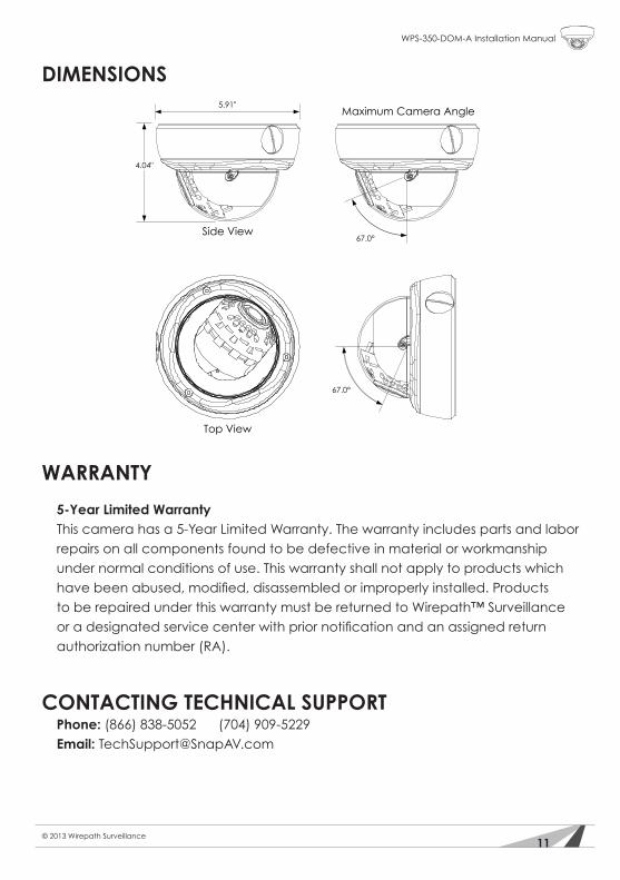
Dimensions 4.04" H x 5.91" W
SPECIFICATIONS
11
WPS-350-DOM-A Installation Manual
© 2013 Wirepath Surveillance
DIMENSIONS
Top View
Side View
5.91"
4.04"
67.0°
67.0°
Maximum Camera Angle
WARRANTY
5-Year Limited Warranty This camera has a 5-Year Limited Warranty. The warranty includes parts and labor repairs on all components found to be defective in material or workmanship under normal conditions of use. This warranty shall not apply to products which havebeenabused,modified,disassembledorimproperlyinstalled.Productsto be repaired under this warranty must be returned to Wirepath™ Surveillance oradesignatedservicecenterwithpriornotificationandanassignedreturnauthorization number (RA).
CONTACTING TECHNICAL SUPPORTPhone: (866) 838-5052 (704) 909-5229Email: [email protected]

© 2013 Wirepath Surveillance
130220-1400
Top Related