


Languages
Pages
Legal

Variances of Variances of Catenary-Pantograph SystemsCatenary-Pantograph Systems
in Standards of Japan and Europe in Standards of Japan and Europe
2011 - 12 - 2011 - 12 - 88
Railway Technical Research InstituteRailway International Standards Center
Hiroki NagasawaShinzo NoguchiTakayuki Usuda
PACIFIC 2011PACIFIC 2011
1
OutlineOutline• Survey the catenary – pantograph systemsSurvey the catenary – pantograph systems in standards of Japan and Europe.in standards of Japan and Europe.• There are many similarities in both systems.There are many similarities in both systems.• Some differences in the design policies.Some differences in the design policies. Both have merits and demerits.Both have merits and demerits.• Examples Examples
– A : Upward force of pantographA : Upward force of pantograph– B : Automatic tensioning methodB : Automatic tensioning method– C : Management of fatigue on contact wire.C : Management of fatigue on contact wire.
Railway International Standards Center 2

Standards for OCL in JapanStandards for OCL in Japan
• Law Law “Railway Operation Act”“Railway Operation Act”• Ministerial Ordinance Ministerial Ordinance to Provide the Technicalto Provide the Technical Standard on Railway (Shorei)Standard on Railway (Shorei)
– performance standardsperformance standards• Approved specification Approved specification for Ministerialfor Ministerial Ordinance … (Kaishaku-kijun)Ordinance … (Kaishaku-kijun)
– Specific examples of the ordinance, not obligatory. Specific examples of the ordinance, not obligatory.
• Japanese Industrial Standards (JISs)Japanese Industrial Standards (JISs)• Other documentsOther documents Manuals, Company CodesManuals, Company Codes
Railway International Standards Center 3

Standards for OCL in EuropeStandards for OCL in Europe
I supposeI suppose•EC DirectivesEC Directives•Technical Specifications for Interoperability Technical Specifications for Interoperability ((TSITSIs) by ERAs) by ERA•European Norms (European Norms (ENENs) s)
– Many ENs are published by CEN and CENELECMany ENs are published by CEN and CENELEC– Examples : EN 50119, 50367, 50388, etc. Examples : EN 50119, 50367, 50388, etc.
Railway International Standards Center 4

A. Upward Force of PantographA. Upward Force of Pantograph
• Contact force of pantograph in JapanContact force of pantograph in Japan– Set to 50 - 65 N at standstill for many lines.Set to 50 - 65 N at standstill for many lines.– When running, it increases by aerodynamic force.When running, it increases by aerodynamic force.– However, it is constrained to around 100 N.However, it is constrained to around 100 N.
• Contact force of pantograph in EuropeContact force of pantograph in Europe– Set to 150 N at standstill for many lines.Set to 150 N at standstill for many lines.– Intentionally increased at standstill Intentionally increased at standstill for carbon strips.for carbon strips.
Railway International Standards Center 5
Features of both systemsFeatures of both systems• The high upward force of pantograph can lead The high upward force of pantograph can lead
to keep steady contact between the to keep steady contact between the pantograph and OCL.pantograph and OCL.
• ReasonsReasons for the small upward force in Japan. for the small upward force in Japan.– To avoid trouble To avoid trouble occurrence caused by large uplift occurrence caused by large uplift
of the contact wire in strong wind. of the contact wire in strong wind. – To avoid breakdown To avoid breakdown of contact wire by fatigue of contact wire by fatigue
from many passages of pantographs.from many passages of pantographs.But it needs means to avoid contact loss of But it needs means to avoid contact loss of
pantograph at high speed running. pantograph at high speed running. Railway International Standards Center 6
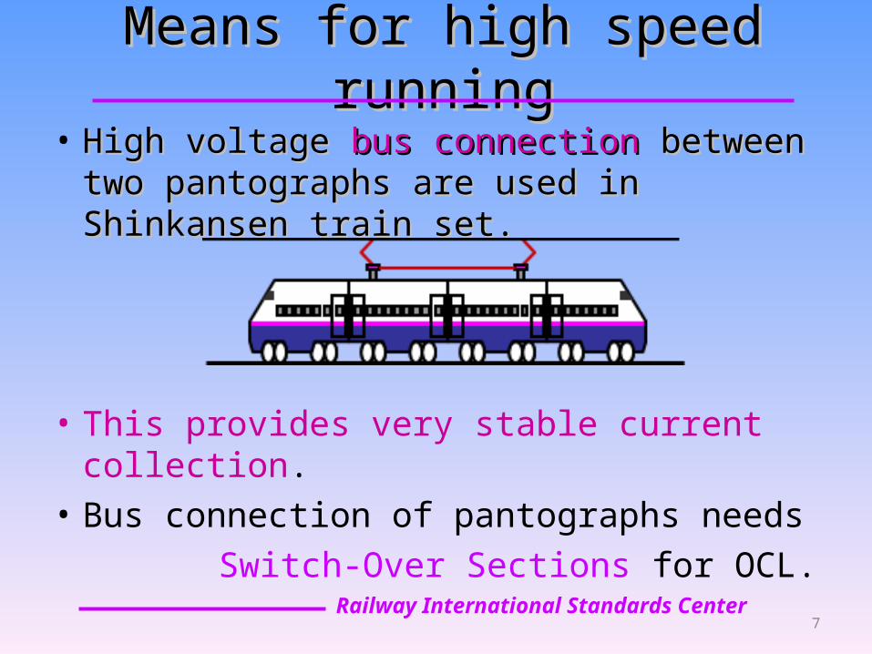
Means for high speed runningMeans for high speed running• High voltage High voltage bus connection bus connection between two between two
pantographs are used in Shinkansen train set.pantographs are used in Shinkansen train set.
• This provides very stable current collection.• Bus connection of pantographs needs Switch-Over Sections for OCL.
Railway International Standards Center 7

Switch 2
Train detector
Switch 1
Composition of Switch-Over SectionComposition of Switch-Over Section
8
≈ 1 km
B. Automatic Tensioning MethodB. Automatic Tensioning Method
• For high speed line in Europe– Use of Two automatic tensioners Use of Two automatic tensioners are
recommended for each contact wire and messenger wire.
– Construction work Construction work for this method is easier than the jointed system (single tensioner).
– Anchoring devices Anchoring devices have to be installed at the mid-points of the whole wire lengths in this method.
Railway International Standards Center 9
Automatic Tensioning Method in Japan
• Several types of tensioners are used– Wheel type Wheel type is the most popular.– many Spring type Spring type tensioners are also used.
• SingleSingle automatic tensioner pulls both pulls both of messenger wire and contact wire by yoke.
• The tension of the device is changed slightly with the position in the stroke of the device.
• Because of the tension control tension control of the device, there is No need for anchoring deviceNo need for anchoring device.
Railway International Standards Center 10
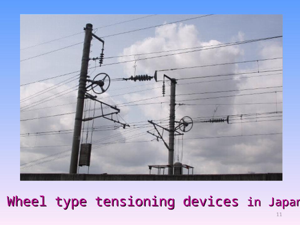
Wheel type tensioning devices Wheel type tensioning devices in Japanin Japan11
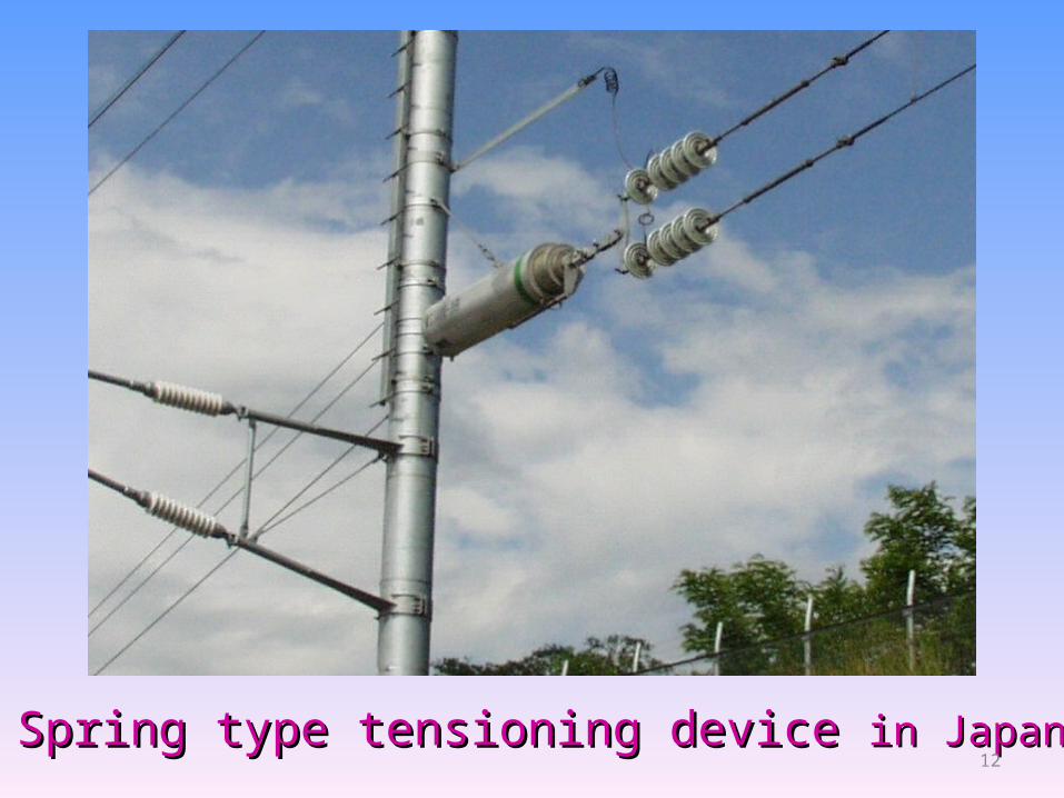
Spring type tensioning device Spring type tensioning device in Japanin Japan12

Tens
ion
Stroke+ S / 2
- S / 2 + 5
%
- 5 %
Example of tension control Example of tension control by automatic tensionerby automatic tensioner in Japan in Japan
13

C. Managing Fatigue on Contact WiresC. Managing Fatigue on Contact Wires
• Contact wire has two major stresses– Tensile stress caused by tension– Bending stress caused by pantograph sliding
• Bending stress increases– with upward force of pantograph– with train running speed
Railway International Standards Center 14
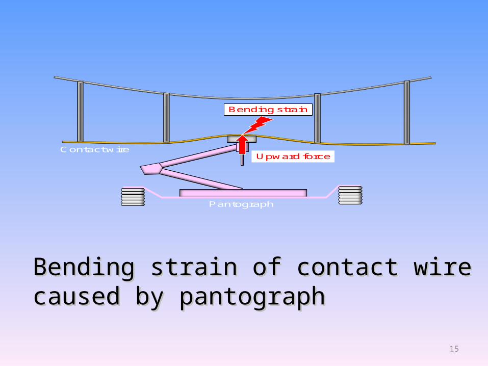
Contact wire
Pantograph
Upward force
Bending strain
Bending strain of contact wireBending strain of contact wirecaused by pantographcaused by pantograph
15

Background of Fatigue ManagementBackground of Fatigue Management
• There are many lines with a large number of trains passing per day in Japan.
• There are several weak points in OCL.• There had been several troubles by fatigue
in the past. • There have been many laboratory and field
tests on fatigue of contact wires.
Railway International Standards Center 16

Hold Support Vibration HoldSupport
Tension
mm
Structure of Fatigue Test EquipmentStructure of Fatigue Test Equipment for Contact Wire for Contact Wire
17
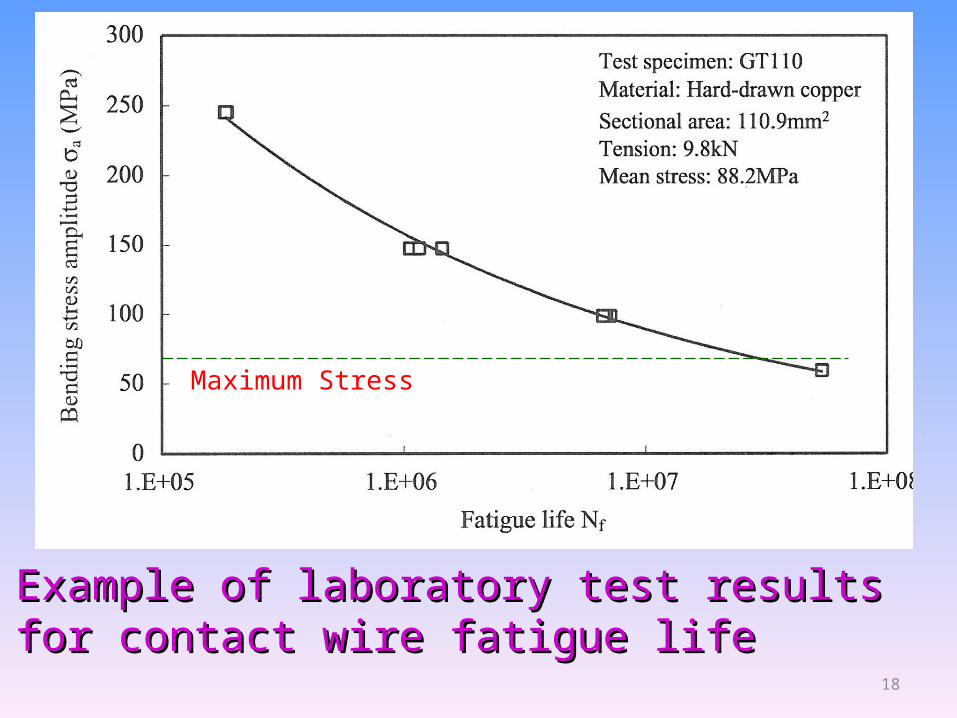
Example of laboratory test results Example of laboratory test results for contact wire fatigue lifefor contact wire fatigue life
Maximum Stress
18

Measurement of contact wire strainMeasurement of contact wire strain
• The strain is measured by strain gauge The strain is measured by strain gauge attached on the contact wire.attached on the contact wire.
• It is not always true that the measuring It is not always true that the measuring point has the largest strain on the line.point has the largest strain on the line.
• We use estimation of bending strain We use estimation of bending strain and setting margin.and setting margin.
Railway International Standards Center 19
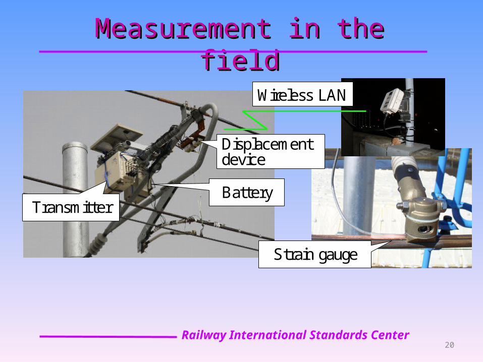
Measurement in the fieldMeasurement in the field
TransmitterBattery
Displacement device
Strain gauge
Wireless LAN
Railway International Standards Center 20
Counter measuresCounter measures for fatigue of contact wires for fatigue of contact wires
• Prevention of pantograph contact force increase
• Lightening of fittings for OCL• Improvement of structure of contact wire
crossing– Improve fitting for crossing – Avoid crossing of contact wires
• Avoidance of mechanical connection of contact wires in high speed area
Railway International Standards Center 21
ConclusionConclusion
• There are many similarities and several differences in standards for OCL in Japan and Europe
• These differences have already been taken into consideration in Working Groups (WGs) of IEC TC9.
• The WGs have been developing several International Standards.
Railway International Standards Center 22
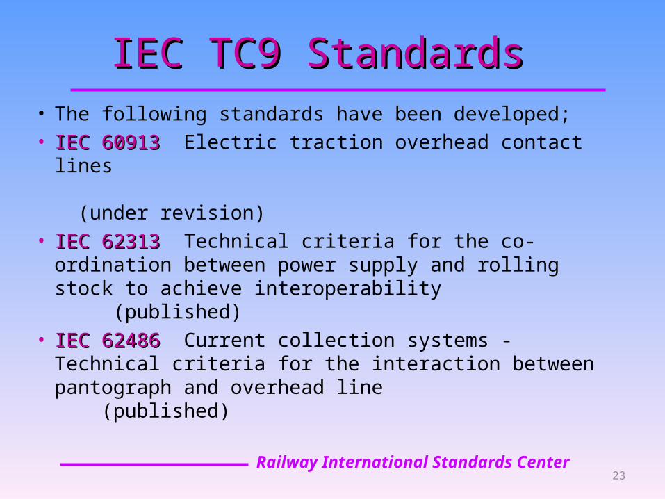
IEC TC9 StandardsIEC TC9 Standards• The following standards have been developed;• IEC 60913 IEC 60913 Electric traction overhead contact lines (under revision)• IEC 62313 IEC 62313 Technical criteria for the co-ordination
between power supply and rolling stock to achieve interoperability (published)
• IEC 62486 IEC 62486 Current collection systems - Technical criteria for the interaction between pantograph and overhead line (published)
Railway International Standards Center 23

Thank you very muchThank you very muchfor your kind attentionfor your kind attention
24
Top Related