


Languages
Pages
Legal

file:///tt/file_convert/55cf8ee3550346703b96ac51/document.xls
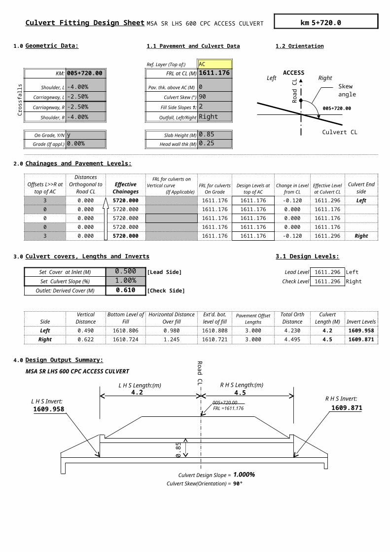
Culvert Fitting Design Sheet MSA SR LHS 600 CPC ACCESS CULVERT km 5+720.0
1.0 Geometric Data: 1.1 Pavement and Culvert Data 1.2 Orientation
Ref. Layer (Top of:) AC
KM: 005+720.00 FRL at CL (M) 1611.176
Cro
ssfa
lls
Shoulder, L -4.00% 0
Carriageway, L -2.50% Culvert Skew (°) 90
Carriageway, R -2.50% 2
Shoulder, R -4.00% Outfall, Left/Right Right
On Grade, Y/N y Slab Height (M) 0.85
Grade (If appl.) 0.00% Head wall thk (M) 0.25
2.0 Chainages and Pavement Levels:
3 0.000 5720.000 1611.176 1611.176 -0.120 1611.296 Left
0 0.000 5720.000 1611.176 1611.176 0.000 1611.176
0 0.000 5720.000 1611.176 1611.176 0.000 1611.176
0 0.000 5720.000 1611.176 1611.176 0.000 1611.176
3 0.000 5720.000 1611.176 1611.176 -0.120 1611.296 Right
3.0 Culvert covers, Lengths and Inverts 3.1 Design Levels:
Set Cover at Inlet (M) 0.500 [Lead Side] Lead Level 1611.296 Left
Set Culvert Slope (%) 1.00% Check Level 1611.296 Right
Outlet: Derived Cover (M) 0.610 [Check Side]
Side
Left 0.490 1610.806 0.980 1610.808 3.000 4.230 4.2 1609.958
Right 0.622 1610.724 1.245 1610.721 3.000 4.495 4.5 1609.871
4.0 Design Output Summary: Right End
MSA SR LHS 600 CPC ACCESS CULVERT Left End
Left plot parameters
Right plot parameters
Degree to radian
Culvert Design Slope = 1.000%Culvert Skew(Orientation) = 90°
Pav. thk. above AC (M)
Fill Side Slopes 1:
Offsets L>>R at top of AC
Distances Orthogonal to
Road CLEffective
Chainages
FRL for culverts on Vertical curve
(If Applicable)
FRL for culverts On
GradeDesign Levels at
top of ACChange in
Level from CL
Effective Level at
Culvert CLCulvert End
side
Vertical Distance
Bottom Level of Fill
Horizontal Distance Over fill
Ext'd. bot. level of fill
Pavement Offset Lengths
Total Orth Distance
Culvert Length (M)
Invert Levels
005+720.00
ACCESS
Roa
d C
L
Culvert CL
Skewangle
Left Right
L H S Length:(m)
1609.958
4.2 4.5
1609.871
Roa
d CL
R H S Length:(m)
L H S Invert: R H S Invert:
FRL =1611.176005+720.00
0.85
Top Related